Embed Size (px)
Citation preview
CSFB Call Flows
CSFB Call Flows From: Network Planning
Unit: Unit name Ver.:1.0
Owner: Voice Services
Page 2 of 12 Release Date: 7/11/2010
Table of contents
1 Introduction .............................................................................................................................. 3
2 Network Architecture for CSFB ............................................................................................ 3
3 SMS over SGs & CSFB Call flows...................................................................................... 4
3.1 Attach Procedure....................................................................................................................4
3.2 Mobile originating SMS ..........................................................................................................5
3.3 Mobile Terminating SMS ........................................................................................................7
3.4 Mobile originating call.............................................................................................................8
3.5 Mobile Terminating Call..........................................................................................................9
4 References............................................................................................................................. 11
5 Abbreviations......................................................................................................................... 11
CSFB Call Flows From: Network Planning
Unit: Unit name Ver.:1.0
Owner: Voice Services
Page 3 of 12 Release Date: 7/11/2010
1 Introduction
The CS FallBack (CSFB) in EPS enables the provisioning of voice and other CS-domain services (e.g. CS UDI video, LCS, USSD) by reuse of CS infrastructure when the UE is served by E-UTRAN. A CSFB enabled terminal, connected to E-UTRAN may use GERAN or UTRAN to connect to the CS-domain. This function is only available in case E-UTRAN coverage is overlapping with either GERAN coverage or UTRAN coverage. The MO SMS and MT SMS are signalled over SGs and do not cause any CS Fallback to GERAN/UTRAN RATs, and consequently does not require any overlapped GERAN/UTRAN coverage.
2 Network Architecture for CSFB
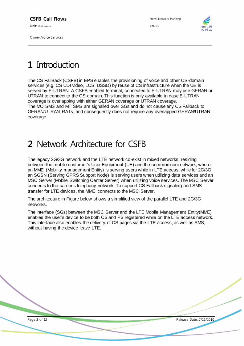
The legacy 2G/3G network and the LTE network co-exist in mixed networks, residing between the mobile customer’s User Equipment (UE) and the common core network, where an MME (Mobility management Entity) is serving users while in LTE access, while for 2G/3G an SGSN (Serving GPRS Support Node) is serving users when utilizing data services and an MSC Server (Mobile Switching Center Server) when utilizing voice services. The MSC Server connects to the carrier’s telephony network. To support CS Fallback signaling and SMS
transfer for LTE devices, the MME connects to the MSC Server.
The architecture in Figure below shows a simplified view of the parallel LTE and 2G/3G
networks.
The interface (SGs) between the MSC Server and the LTE Mobile Management Entity(MME) enables the user’s device to be both CS and PS registered while on the LTE access network. This interface also enables the delivery of CS pages via the LTE access, as well as SMS, without having the device leave LTE.
CSFB Call Flows From: Network Planning
Unit: Unit name Ver.:1.0
Owner: Voice Services
Page 4 of 12 Release Date: 7/11/2010
3 SMS over SGs & CSFB Call flows
3.1 Attach Procedure
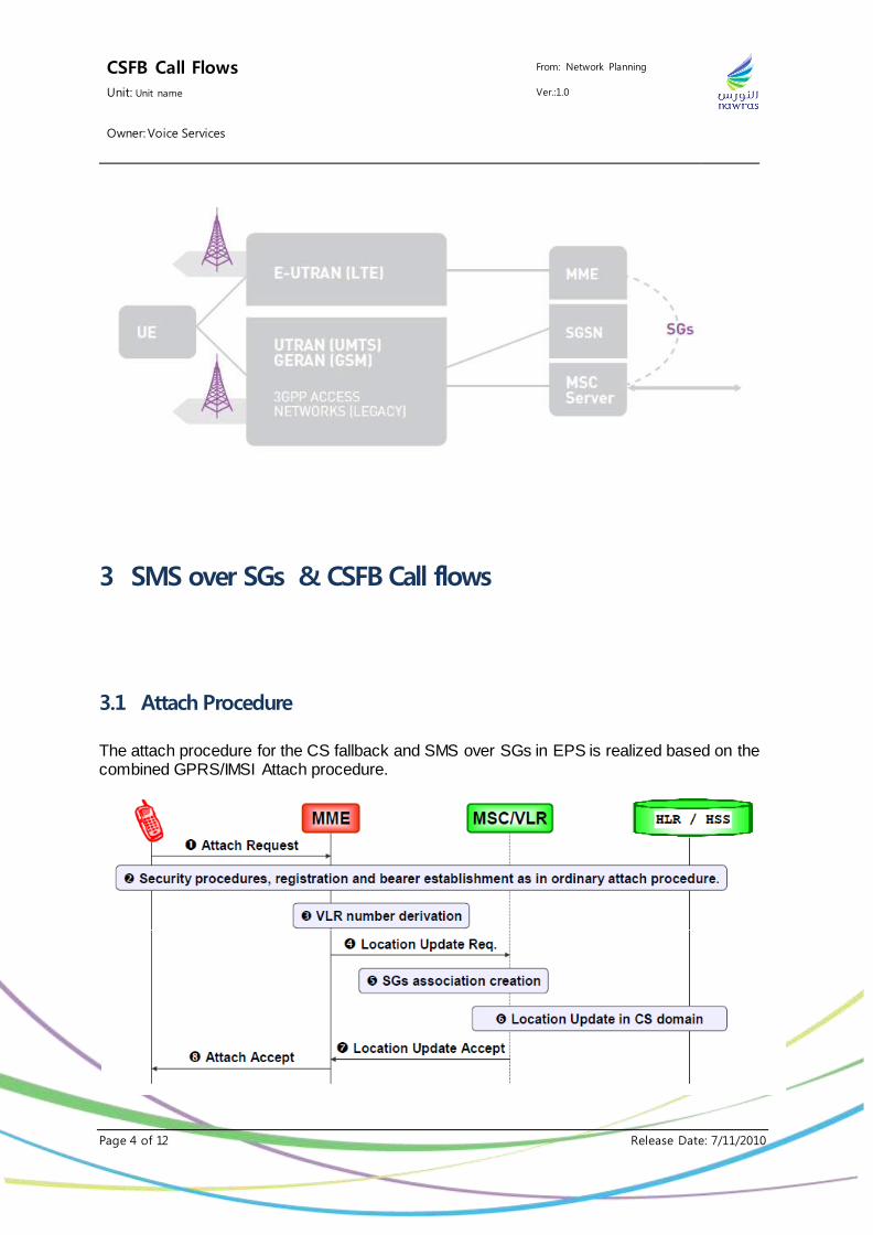
The attach procedure for the CS fallback and SMS over SGs in EPS is realized based on the combined GPRS/IMSI Attach procedure.
CSFB Call Flows From: Network Planning
Unit: Unit name Ver.:1.0
Owner: Voice Services
Page 5 of 12 Release Date: 7/11/2010
1) The UE initiates the attach procedure by the transmission of an Attach Request message to the MME. The Attach Type parameter indicates that the UE requests a combined EPS/IMSI attach and informs the network that the UE is capable and configured to use CS fallback.
2) Security procedures, registration and default bearer establishment as in ordinary EPS Attach procedure.
3) The MME allocates a default LAI, which is configured on the MME and may take into
account the current TAI and/or E-CGI and whether the IMSI attach is for both CSFB and SMS, or for SMS only. The MME derives a VLR number based on the allocated LAI and IMSI. The MME starts the location update procedure towards the new MSC/VLR upon receipt of the subscriber data from the HSS in step 2.
4) The MME sends a Location Update Request (new LAI, IMSI, MME name, Location Update Type) message to the VLR. MME name is the FQDN string.
5) The VLR creates an association with the MME by storing MME address.
6) The VLR performs the normal subscription checks for CS and if all checks are successful VLR performs Location Updating procedure in CS domain.
7) The VLR responds with Location Update Accept (TMSI) to the MME.
8) The EPS Attach procedure is completed. Attach Accept message includes LAI and
TMSI. The existence of LAI and TMSI indicates successful attach to CS domain.
3.2 Mobile originating SMS
CSFB Call Flows From: Network Planning
Unit: Unit name Ver.:1.0
Owner: Voice Services
Page 6 of 12 Release Date: 7/11/2010
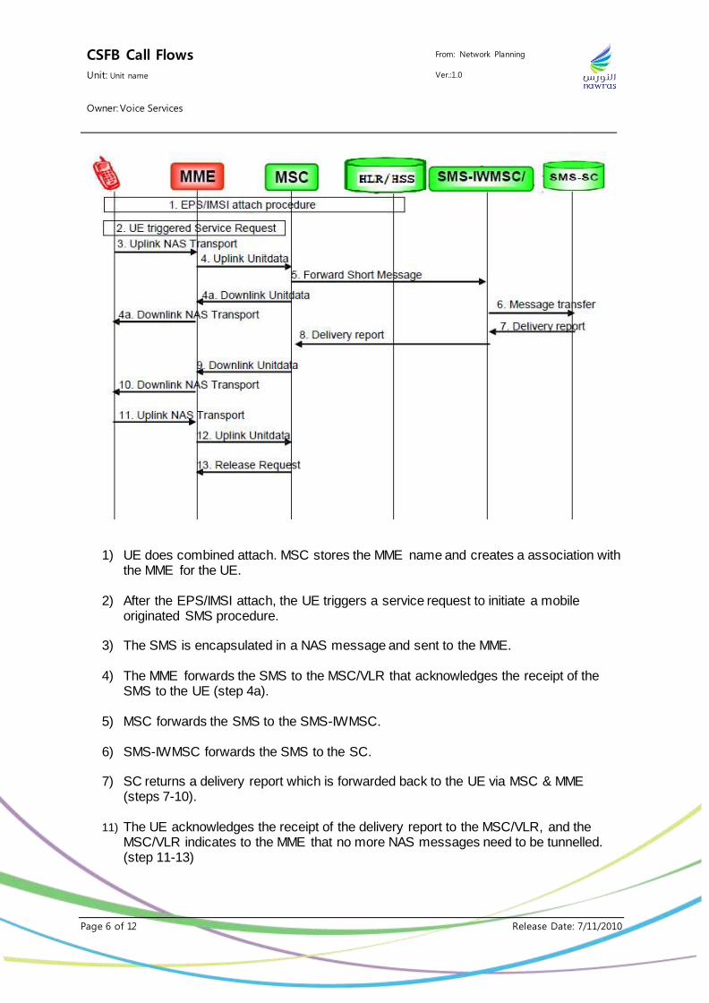
1) UE does combined attach. MSC stores the MME name and creates a association with the MME for the UE.
2) After the EPS/IMSI attach, the UE triggers a service request to initiate a mobile originated SMS procedure.
3) The SMS is encapsulated in a NAS message and sent to the MME.
4) The MME forwards the SMS to the MSC/VLR that acknowledges the receipt of the
SMS to the UE (step 4a).
5) MSC forwards the SMS to the SMS-IWMSC.
6) SMS-IWMSC forwards the SMS to the SC.
7) SC returns a delivery report which is forwarded back to the UE via MSC & MME (steps 7-10).
11) The UE acknowledges the receipt of the delivery report to the MSC/VLR, and the
MSC/VLR indicates to the MME that no more NAS messages need to be tunnelled. (step 11-13)
CSFB Call Flows From: Network Planning
Unit: Unit name Ver.:1.0
Owner: Voice Services
Page 7 of 12 Release Date: 7/11/2010
3.3 Mobile Terminating SMS
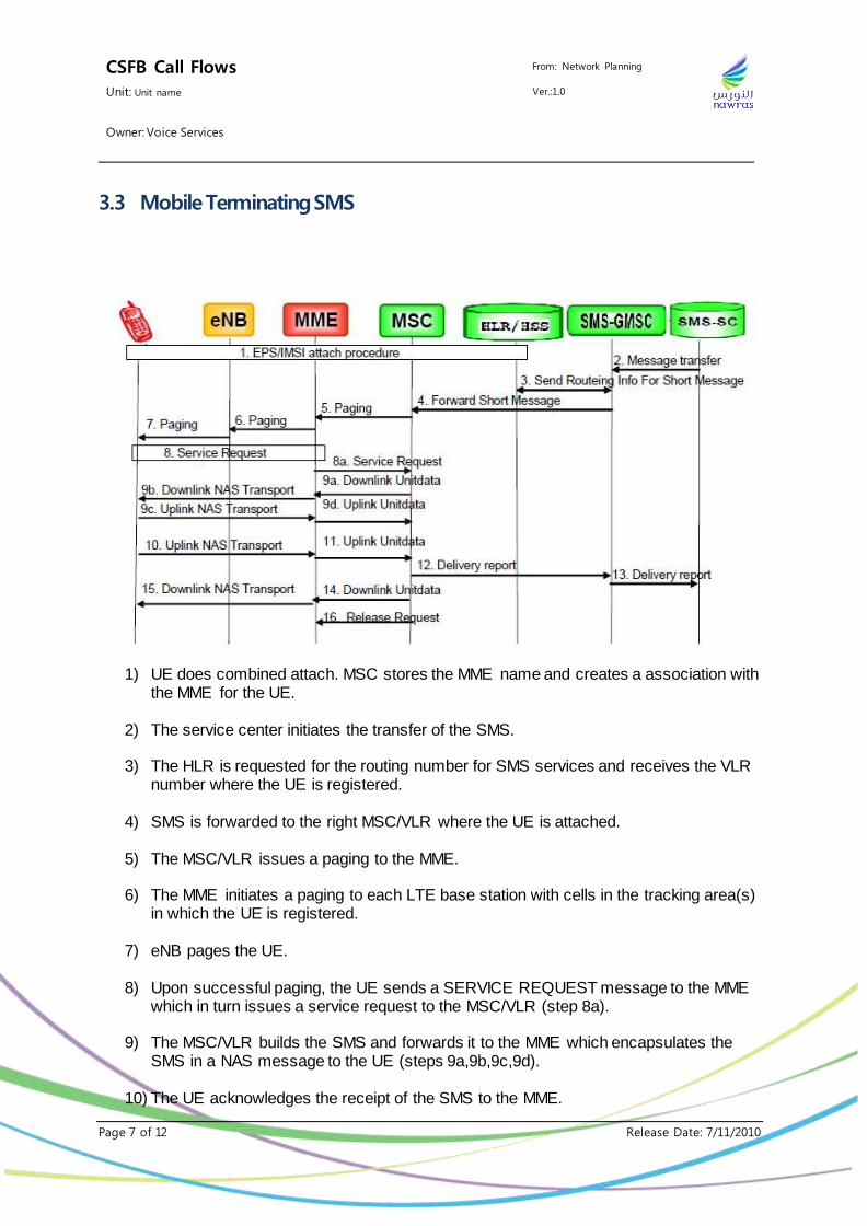
1) UE does combined attach. MSC stores the MME name and creates a association with the MME for the UE.
2) The service center initiates the transfer of the SMS.
3) The HLR is requested for the routing number for SMS services and receives the VLR number where the UE is registered.
4) SMS is forwarded to the right MSC/VLR where the UE is attached.
5) The MSC/VLR issues a paging to the MME.
6) The MME initiates a paging to each LTE base station with cells in the tracking area(s)
in which the UE is registered.
7) eNB pages the UE.
8) Upon successful paging, the UE sends a SERVICE REQUEST message to the MME which in turn issues a service request to the MSC/VLR (step 8a).
9) The MSC/VLR builds the SMS and forwards it to the MME which encapsulates the
SMS in a NAS message to the UE (steps 9a,9b,9c,9d).
10) The UE acknowledges the receipt of the SMS to the MME.
CSFB Call Flows From: Network Planning
Unit: Unit name Ver.:1.0
Owner: Voice Services
Page 8 of 12 Release Date: 7/11/2010
11) MME relays the acknowledge from the UE to the MSC/VLR.
12) MSC/VLR issues the delivery report to the SMS-SMSC.
13) The delivery report is forwarded to the service center.
14) The MSC/VLR acknowledges the receipt of the delivery report to the UE via MME
which encapsulates it into a NAS message (step 15).
16) MSC/VLR indicates to the MME that no more NAS messages need to be tunnelled.
3.4 Mobile originating call
CSFB Call Flows From: Network Planning
Unit: Unit name Ver.:1.0
Owner: Voice Services
Page 9 of 12 Release Date: 7/11/2010
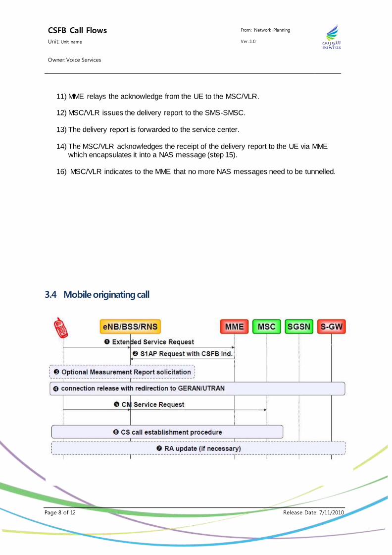
1) The UE which has done combined attach and registered in both MME and MSC sends an Extended Service Request (CS Fallback Indicator) to MME. CS Fallback Indicator indicates MME to perform CS Fallback.
2) The MME sends an S1-AP Request message to eNB that includes a CS Fallback
indicator. This message indicates to the eNB that the UE should be moved to UTRAN/GERAN.
3) The eNB may optionally solicit a measurement report from the UE to determine the
target GERAN/UTRAN cell.
4) The eNB triggers connection release with redirection to UTRAN.
5) The UE establishes CS signalling connection in the target RAT and sends CM Service Request message. The simultaneous support of packet data bearers depends on selected RAT and additional features like e.g. DTM.
6) The UE initiates the CS call establishment procedure.
7) The UE may trigger the RA update procedure when the sending of uplink packet data
is possible.
3.5 Mobile Terminating Call
CSFB Call Flows From: Network Planning
Unit: Unit name Ver.:1.0
Owner: Voice Services
Page 10 of 12 Release Date: 7/11/2010
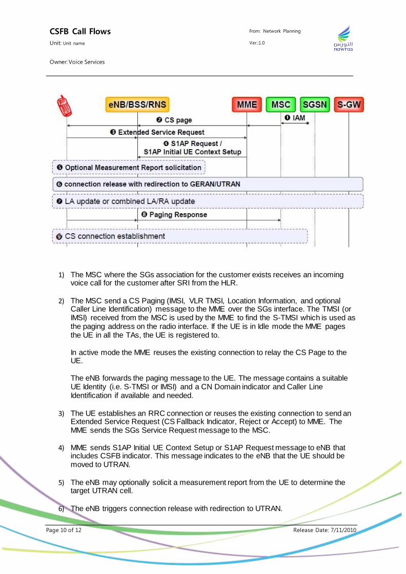
1) The MSC where the SGs association for the customer exists receives an incoming voice call for the customer after SRI from the HLR.
2) The MSC send a CS Paging (IMSI, VLR TMSI, Location Information, and optional Caller Line Identification) message to the MME over the SGs interface. The TMSI (or IMSI) received from the MSC is used by the MME to find the S-TMSI which is used as the paging address on the radio interface. If the UE is in Idle mode the MME pages the UE in all the TAs, the UE is registered to. In active mode the MME reuses the existing connection to relay the CS Page to the UE. The eNB forwards the paging message to the UE. The message contains a suitable UE Identity (i.e. S-TMSI or IMSI) and a CN Domain indicator and Caller Line Identification if available and needed.
3) The UE establishes an RRC connection or reuses the existing connection to send an Extended Service Request (CS Fallback Indicator, Reject or Accept) to MME. The MME sends the SGs Service Request message to the MSC.
14
4) MME sends S1AP Initial UE Context Setup or S1AP Request message to eNB that includes CSFB indicator. This message indicates to the eNB that the UE should be moved to UTRAN.
5) The eNB may optionally solicit a measurement report from the UE to determine the target UTRAN cell.
6) The eNB triggers connection release with redirection to UTRAN.
CSFB Call Flows From: Network Planning
Unit: Unit name Ver.:1.0
Owner: Voice Services
Page 11 of 12 Release Date: 7/11/2010
7) If the UE obtains LA/RA information of the new UTRAN/GERAN cell (e.g. based on the system information or redirection info) and the LA/RA of the new cell is different from the one stored in the UE, it performs a Location Area Update or a Combined RA/LA procedure if the target system operates in NMO I
8) The UE establishes CS signalling connection in the target RAT and sends Paging
Response message. The simultaneous support of packet data bearers depends on selected RAT and additional features like e.g. DTM.
9) MSC stops the paging response timer and establish the CS connection.
4 References
1) Circuit Switched (CS) fallback in Evolved Packet System (EPS); Stage 2 (3GPP TS 23.272 version 10.4.0 Release 10)
2) Mobility Management Entity (MME) - Visitor Location Register (VLR) SGs interface specification (3GPP TS 29.118 version 10.9.0 Release 10)
5 Abbreviations
3G 3-rd Generation 3GPP 3rd Generation Partnership Project CS Circuit Switched CSFB Circuit Switched Fallback EPS Evolved Packet System E-UTRAN Evolved universal terrestrial radio access network eNB e-NodeB GPRS General Packet Radio Service GERAN GSM EDGE radio access network GSM Global system for mobile communications HLR Home location register HSS Home Subscriber Server HTTP Hypertext Transfer Protocol IP Internet Protocol IMSI International mobile subscriber identity LTE Long term evolution MME Mobility management entity MSC Mobile switching center
CSFB Call Flows From: Network Planning
Unit: Unit name Ver.:1.0
Owner: Voice Services
Page 12 of 12 Release Date: 7/11/2010
NAS Non-access stratum PDN Packet data network P-GW Packet data network gateway PLMN Public land mobile network PS Packet Switched RAN Radio access network SC Service center SGSN Serving GPRS support node S-GW Serving gateway SMS Short Message Service SMS-GMSC Gateway MSC for short message service SMS-IWMSC Interworking MSC for short message service TMSI Temporary Mobile Subscriber Identity UMTS Universal mobile telecommunications system USIM Universal subscriber identity module VLR Visitor Location Register