Embed Size (px)
DESCRIPTION
sed
Citation preview
Definitions :-
CSFB (Circuit Switched Fallback):- is a functionality specified by 3GPP to provide legacy circuit switched services (like voice, SMS, call independent supplementary services, location services, ...) for LTE UEs when they are attached in LTE coverage.
This is achieved by falling back to GERAN or UTRAN in case those services are requested.The CSFB functionality needs to be implemented in the UE, the E-UTRAN, the EPC (MME), the MSS/VLR, the HLR (in case of MTRR, MTRF). To support moving back from GERAN/UTRAN to LTE functionality in GERAN/UTRAN is required.
Circuit Switched Fall Back (CSFB) :-
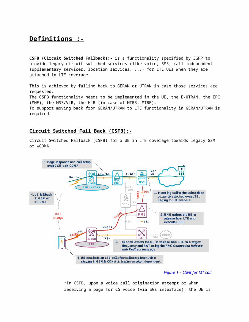
Circuit Switched Fallback (CSFB) for a UE in LTE coverage towards legacy GSM or WCDMA.
LTE
GSM / WCDMA
S1-U
e-Uu
Abis / IubUm / Uu
S1-MME
S11
SGs
A / IuCS
BTSNodeB
BTSNodeB
BTSNodeB
eNodeBeNodeBeNodeB
MMEMMEMME
BSCRNCBSCRNCBSCRNC
MMEMMEMME
MSSMSSMSS
SGSNSGSNSGSN S3
Gb /IuPS
S4
S&PGWS&PGWS&PGW
RATchange
Nc /Nb
InternetInternetSGi
B
AA
1. Incoming call to the subscriber currently attached over LTE. Paging in LTE via SGs.
4. UE fall back to GSM or WCDMA
5. Page response and call setup over GSM or WCDMA
2. MME orders the UE to release from LTE and execute CSFB
Pagi
ng
Paging
6. UE reselects an LTE cell after call completion, time staying in GSM/WCDMA is implementation dependent
3. eNodeB orders the UE to release from LTE to a target frequency and RAT using the RRC Connection Release with Redirect message
Paging
Figure 1 – CSFB for MT call
“In CSFB, upon a voice call origination attempt or when receiving a page for CS voice (via SGs interface), the UE is moved to UMTS/GSM and the voice is sent over one of these access networks. The page response is sent over the new RAT on the Iu or A interface. The UE will return to LTE after call completion if LTE is preferred and coverage exists”.
The CSFB function is only possible to realize in areas where E-UTRAN coverage is overlapped with GSM and WCDMA coverage
CSFB will allow retaining current roaming relationships between operators, since CS voice is still used.
CSFB Implementation Alternatives
There are 2 main CSFB procedures:
› RRC Release with Redirect
Basic CSFB: without target RAN System Information (SI)
Enhanced CSFB:
o Deferred Measurement Control Reading (WCDMA)
o SI exchange based on 3GPP RIM procedures (GSM and WCDMA)
› PSHO (Packet Switched Handover)
Depending on the CSFB procedure different network elements are affected and different CSFB performance can be achieved, which is shown in the following sections.
Basic RRC release with redirect without SI exchange
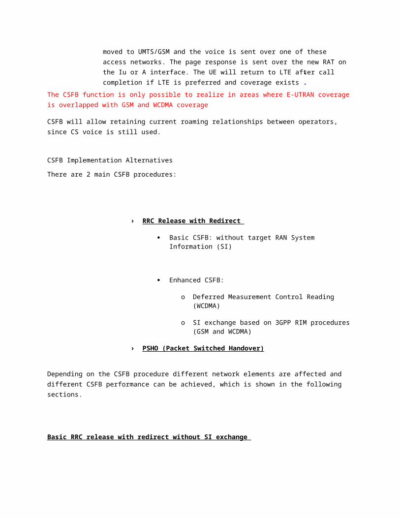
The basic CSFB option is RRC Release with Redirect without SI exchange between WCDMA/GSM and LTE RAN. The impacted nodes are indicated by the CSFB in the circle.
LTE
GSM / WCDMA
S1-U
e-Uu
Abis / IubUm / Uu
S1-MME
S11
SGs
A / IuCS
BTSNodeBBTS
NodeBBTS
NodeB
eNodeBeNodeBeNodeB
MMEMMEMME
BSCRNCBSCRNCBSCRNC
MMEMMEMME
MSSMSSMSS
SGSNSGSNSGSNS3
Gb /IuPS
S4
S&PGWS&PGWS&PGW
RATchange
Nc /Nb
InternetInternetSGi
BCSFB
CSFB
CSFB
CSFBphone
AA
AA
CSFB
› Impact: UE, eNB, MME and MSC› Characteristics:
– CS: ~1.5s (UTRAN) / ~2.5s (GERAN) higher call setup time– PS: stop in non-DTM GERAN or RAU to establish PS bearers (5-6s)
Figure 2 – Basic CSFB with RRC Connection Release & Redirect
Impacted nodes are UE, eNB, MME and MSC. No impact exists for GSM or WCDMA, which consequently does not require a rollout of new software in the legacy radio network. In an MSC pool environment only few MSCs need to support SGs, as each MSC serve all LAs of the pool.
Main characteristics:
› Slower call set-up time because SI needs to be fetched by the UE in the target RAN
› Longer PS outage time for WCDMA or DTM GSM as no PSHO is performed
E2e Functionality already available. Basic CSFB supported from: MSC-S 12A, MME 2011A and L11 B (LTE Radio).
Enhanced RRC release with redirect, Deferred Measurement Control Reading (DMCR) procedures (WCDMA)
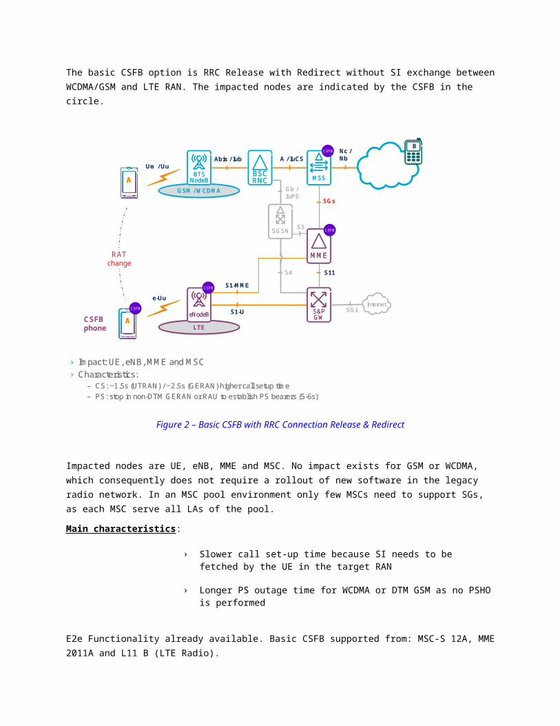
The DMCR feature avoids reading specific SIBs with information that can be received at another occasion. The maximum time for reading system information without this indication is 1280ms.
LTE
WCDMA
S1-U
e-Uu
Iub
S1-MME
S11
SGs
IuCS
NodeBNodeBNodeB
eNodeBeNodeBeNodeB
MMEMMEMME
RNCRNCRNC
MMEMMEMME
MSSMSSMSS
SGSNSGSNSGSN S3
IuPS
S4
S&PGWS&PGWS&PGW
RATchange
Nc /Nb
InternetInternetSGi
BCSFB
CSFB
CSFB
CSFBphone
AA
AA
CSFB
› Impact: RNC + basic CSFB (First CSFB UE support DMCR by default)› Characteristics:
– CS: ~0.8s higher call setup time for UTRAN– PS: stop in non-DTM GERAN or RAU to establish PS bearers (5-6s)
DMCR
UE reads only essential SIB
Figure 3 – CSFB with Deferred Measurement Control Reading (WCDMA)
in RNC Additional Nodes impacted: DMCR support
Additional Network Impact: DMCR to be rolled out in RNC
Benefit: faster call set-up times compared to the non enhanced solution.
Enhanced RRC release with redirect, automatic system info exchange with RIM (GSM & WCDMA)
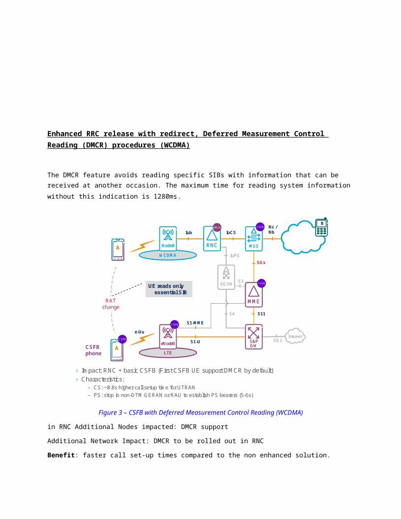
The standardized RIM procedures allow the transfer of SI from GSM or WCDMA to LTE. This requires additional impact on the total network. RIM needs to be rolled-out in the source and target RAN as well as
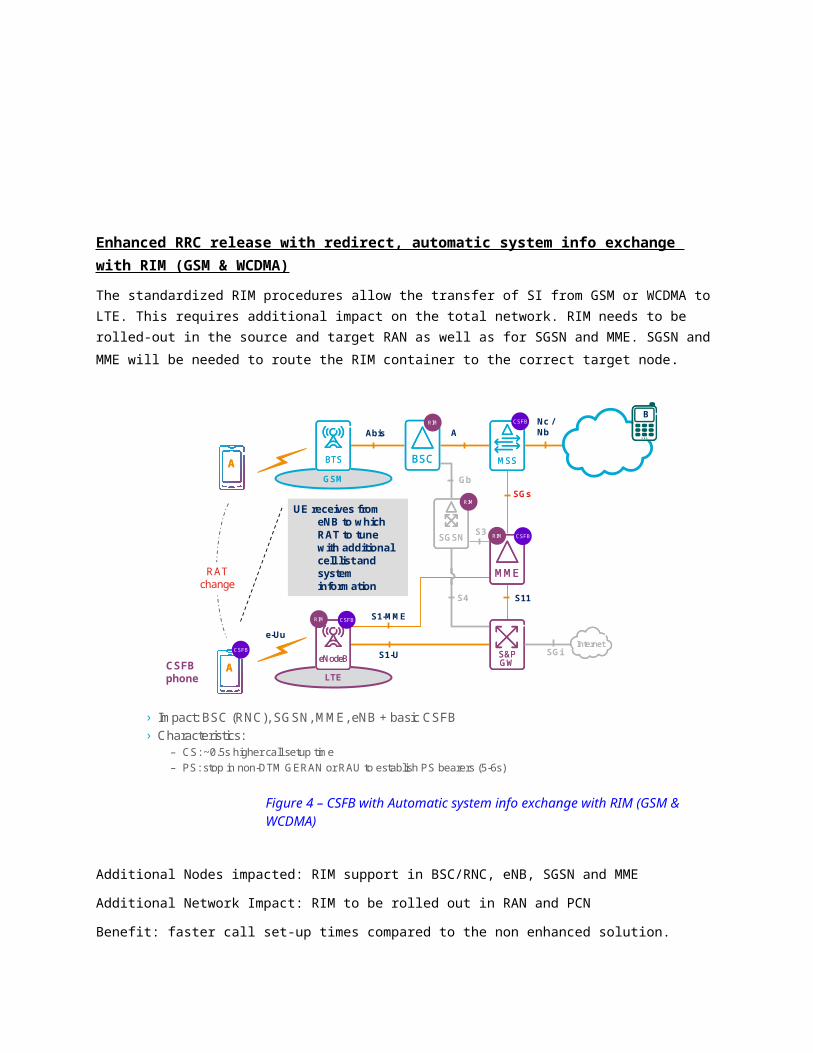
for SGSN and MME. SGSN and MME will be needed to route the RIM container to the correct target node.
LTE
GSM
S1-U
e-Uu
Abis
S1-MME
S11
SGs
A
BTSBTSBTS
eNodeBeNodeBeNodeB
MMEMMEMME
BSCBSCBSC
MMEMMEMME
MSSMSSMSS
SGSNSGSNSGSNS3
Gb
S4
S&PGWS&PGWS&PGW
RATchange
Nc /Nb
InternetInternetSGi
BCSFB
CSFB
CSFB
CSFBphone
AA
AA
CSFB
UE receives from eNB to which RAT to tune with additional cell list and system information
› Impact: BSC (RNC), SGSN, MME, eNB + basic CSFB › Characteristics:
– CS: ~0.5s higher call setup time – PS: stop in non-DTM GERAN or RAU to establish PS bearers (5-6s)
RIM
RIM
RIM
RIM
Figure 4 – CSFB with Automatic system info exchange with RIM (GSM & WCDMA)
Additional Nodes impacted: RIM support in BSC/RNC, eNB, SGSN and MME
Additional Network Impact: RIM to be rolled out in RAN and PCN
Benefit: faster call set-up times compared to the non enhanced solution.
E2e Functionality available in Q2 2012. On top of basic CSFB, RIM support in GSM, WCDMA and LTE radio is planned for: G12A (GSM Radio), W12B (WCDMA Radio), L12B (LTE Radio). RIM support in MME-SGSN is already available from MME-SGSN 2011B
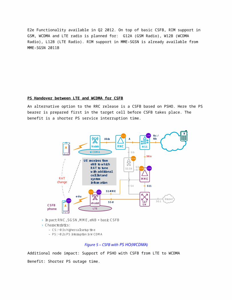
PS Handover between LTE and WCDMA for CSFB
An alternative option to the RRC release is a CSFB based on PSHO. Here the PS bearer is prepared first in the target cell before CSFB takes place. The benefit is a shorter PS service interruption time.
LTE
WCDMA
S1-U
e-Uu
Abis
S1-MME
S11
SGs
A
NodebNodebNodeb
eNodeBeNodeBeNodeB
MMEMMEMME
RNCRNCRNC
MMEMMEMME
MSSMSSMSS
SGSNSGSNSGSN S3
Gb
S4
S&PGWS&PGWS&PGW
RATchange
Nc /Nb
InternetInternetSGi
BCSFB
CSFB
CSFB
CSFBphone
AA
AA
CSFB
UE receives from eNB to which RAT to tune with additional cell list and system information
› Impact: RNC, SGSN, MME, eNB + basic CSFB › Characteristics:
– CS: ~0.5s higher call setup time – PS: ~0.2s PS interruption in WCDMA
PS HO
PS HO
PS HO
PS HO
Figure 5 – CSFB with PS HO(WCDMA)
Additional node impact: Support of PSHO with CSFB from LTE to WCDMA
Benefit: Shorter PS outage time.
E2e Functionality available in Q2 2012. On top of basic CSFB, PS HO support in WCDMA and LTE radio is planned for: W12B (WCDMA Radio) and L13 (LTE Radio). PS HO support in MME-SGSN is already available from MME-SGSN 2011B (S3 based).
Steering of CSFB calls to a prioritized target RAT and frequency
The eNB can send the UE back to GSM or WCDMA depending on the operator setting of the preferred target RAT (with highest priority). An RRC Release wit
Redirect will always be performed to a specific RAT and frequency (not to cell).
It should be noted that the eNB cannot include a list of allowed cells in the CSFB RRC Release with Redirect, to enssure that CSFB calls will be steered to GSM/WCDMA cells belonging to the right MSC (where the subscriber is registered in).
It should also be noted that in case the UE does not support target RAT or the LTE cell has not full overlay in target RAT, the lower priority RAT will be chosen. If the network has different MSCs for the different RATs then the call will fail unless we have MTRF or MTRR functionality deployed.
Umbrella Cells
GSM/WCDMA umbrella cells can increase probability that all LTE-border cells are completely covered by cells from the correct MSC (registered MSC). The UE might select these umbrella cells if the signal strength is better than the signal of the other cells. However cell selection is up to the UE and it is not guaranteed that umbrella cell will be chosen.
MSC with Dual Access
Deployment of dual access MSC will reduce the need for MTRF/MTRR when the UE selects the lower priority RAT.
MSC in Pool
With MSC pool all MSCs serve all LA within the pool (prerequisite is that all RNC and BSC are pool aware or the pool proxy functionality is activated in the M-MGW).
The areas where MTRF/MTRR would be required are limited to the pool border areas. Border areas are typically located between regions in low dense areas where large GSM cells are used. It much more likely that the GSM and LTE cells would be aligned at these MSC pool borders, so the need of MTRF/MTRR will affect a lower number of calls.
Also, the SGs-interface can be implemented in one or a few number of MSCs in initial migration steps and then SGs in more MSCs can be added when more capacity is needed.
Mobile Terminating Roaming Forwarding
MT Roaming Forwarding (MTRF) will allow that the MSC/VLR where the UE is registered to route the call further to the MSC where the UE has fallen back to. The probability is higher that this use case occurs if no MSC pool is deployed (at MSC borders) or when MSC pool is deployed it can occur as MSC pool border areas. MTRF functionality impacts only in MSC.
Additional delay has to be added for an inter-MSC roaming forwarding procedure (2-6 seconds).
MTRF is recommended over MTRR for the following reasons:
Shorter call setup times :-MTRF solution forwards the call directly between the concerned VMSC’s. MTRR solution sends the call back from the VMSC to the GMSC which then makes a second interrogation to the HLR. Extra routing and interrogation, longer call setup process especially for international call cases.
Better suited for multi-vendor and inter-operator scenarios:- MTRF can be implemented in the visited network only. MTRR must be implemented in the VMSC, GMSC and HLR layers. With MTRR for CSFB all roaming agreements need to be revised and checked in order to assure that the function will work e2e.
Less signaling traffic
Optimization of Call Set up Delay
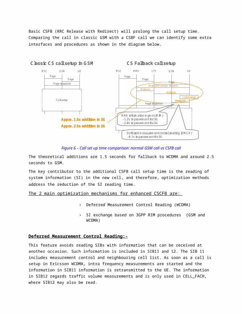
Basic CSFB (RRC Release with Redirect) will prolong the call setup time. Comparing the call in classic GSM with a CSBF call we can identify some extra interfaces and procedures as shown in the diagram below.
Classic CS call setup in GSM CS Fallback call setup
Cell changeRead SI
PagePage
Extended service requestRelease
Page response
PagePage
Page response
MSC UEGSM MSC UEMME GSM
Page
LTE
Release
Call setupCall setup
Call setupCall setupRAN information mgmnt (RIM)- 1.2s improvement for 3G- 2.0s improvement for 2G
Deferred measurement control reading (DMCR)- 0.7s improvement for 3G
Apprx. 1.5s addition in 3G
Apprx. 2.5s addition in 2G
Apprx. 1.5s addition in 3G
Apprx. 2.5s addition in 2G
Figure 6 – Call set up time comparison: normal GSM call vs CSFB call
The theoretical additions are 1.5 seconds for fallback to WCDMA and around 2.5 seconds to GSM.
The key contributor to the additional CSFB call setup time is the reading of system information (SI) in the new cell, and therefore, optimization methods address the reduction of the SI reading time.
The 2 main optimization mechanisms for enhanced CSCFB are:
› Deferred Measurement Control Reading (WCDMA)
› SI exchange based on 3GPP RIM procedures (GSM and WCDMA)
Deferred Measurement Control Reading:-
This feature avoids reading SIBs with information that can be received at another occasion. Such information is included in SIB11 and 12. The SIB 11 includes measurement control and neighbouring cell list. As soon as a call is setup in Ericsson WCDMA, intra frequency measurements are started and the information in SIB11 information is retransmitted to the UE. The information in SIB12 regards traffic volume measurements and is only used in CELL_FACH, where SIB12 may also be read.
To tell the UE to skip reading SIB11 and 12 an indication is needed in SIB3, stating that this WCDMA network supports “Deferred Measurement Control Reading”. The maximum time for reading system
information without this indication is 1280ms; omitting SIB11 and 12 would decrease this worst case time to 640ms.
As indicated in previous answer WCDMA support of this feature is planned for W12B (WCDMA RAN). No impact in other areas of the network.
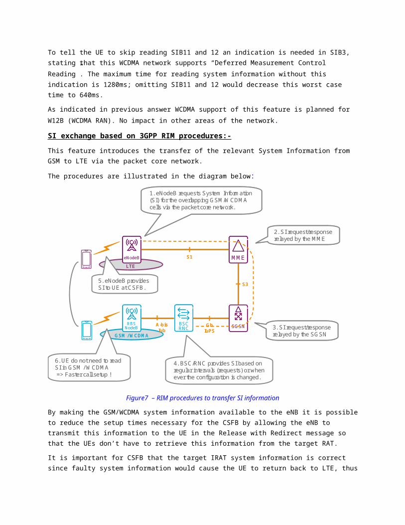
SI exchange based on 3GPP RIM procedures:-
This feature introduces the transfer of the relevant System Information from GSM to LTE via the packet core network.
The procedures are illustrated in the diagram below:
GSM / WCDMA
MMEMMEMMEeNodeBeNodeBeNodeB
S3
S1
GbIuPS
RBSNodeBRBS
NodeBRBS
NodeB
LTE
BSCRNCBSCRNCBSCRNC
A-bisIub
SGSNSGSN
4. BSC/RNC provides SI based on regular intervals (requests) or when ever the configuration is changed.
6. UE do not need to read SI in GSM / WCDMA=> Faster call setup !
5. eNodeB provides SI to UE at CSFB.
1. eNodeB requests System Information (SI) for the overlapping GSM/WCDMA cells via the packet core network.
1. eNodeB requests System Information (SI) for the overlapping GSM/WCDMA cells via the packet core network.
2. SI request/response relayed by the MME2. SI request/response relayed by the MME
3. SI request/response relayed by the SGSN3. SI request/response relayed by the SGSN
Figure7 – RIM procedures to transfer SI information
By making the GSM/WCDMA system information available to the eNB it is possible to reduce the setup times necessary for the CSFB by allowing the eNB to transmit this information to the UE in the Release with Redirect message so that the UEs don’t have to retrieve this information from the target RAT.
It is important for CSFB that the target IRAT system information is correct since faulty system information would cause the UE to return back to LTE, thus causing the CSFB to fail. So in order for this approach to work there must be a reliable system information delivery mechanism that makes it possible for the eNB to always have correct system information.
This can e.g. be done by the 3GPP specified RIM procedures. This would enable the eNB to supply the correct system information to the UE and this would enable the UE to access the target RAT without having to read the target system information and be able to access the target RAT more quickly. RIM procedures require support in the eNB, MME, SGSN and RNC/BSC. The RNC/BSC is responsible for
creating and distributing the system information to the eNB and the MME/SGSN are responsible for routing the RIM.
On top of basic CSFB, RIM support in GSM, WCDMA and LTE radio is planned
Optimization of call success rate
Call success rate, MSC load and overall CSFB performance are optimized by the use of the Network Design Recommendations explained in the previous answer:
Steering of CSFB calls to a prioritized target RAT and frequency
Umbrella Cells
MSC with Dual Access
MSC in Pool
Mobile Terminating Roaming Forwarding
It is important to highlight that Dual Access MSC and MSC in Pool features will minimize the number of calls where MTRF or MTRR would be needed, eliminating the additional call set up time caused by these procedures (additional 2 to 10 seconds for MTRR) and reducing signalling load over MSCs.
Optimization of E-UTRAN return time
Fast Return to LTE (GSM)
This feature enables a faster re-selection to LTE at TCH/SDCCH release, i.e. when a service over a CS connection is terminated.
In case of DTM operation, when the CS connection of the DTM operation is released then the UE will automatically drop the PS connection. This means that the UE will obey the redirection information if provided at TCH release. Hence the behaviour is very similar to the ordinary case of a plain CS connection release.
Idle Mode Cell Reselection (WCDMA)
When the CS call is ended the UE will return to LTE by the WCDMA feature “Idle Mode Cell Reselection”, provided that it has no active PS connection
If the UE has an active PS connection in Cell_DCH or Cell_FACH in WCDMA it will stay there as long as there is an ongoing communication. When the PS connection becomes inactive the UE goes to URA_PCH or Idle and returns to LTE by Idle Mode Cell Reselection, given that LTE has been set as the preferred RAT in the broadcast information in WCDMA.
E-UTRAN
MME
Serving/PDN GW
SGi
1xRTT CS Access
1xRTT MSC
1xCS IWS
S102
S11 S1-MME
S1-U
A1
A1
Tunnelled 1xRTT messages
1xCS CSFB
UE
1xCS CSFB
UE
1x CS
EPC
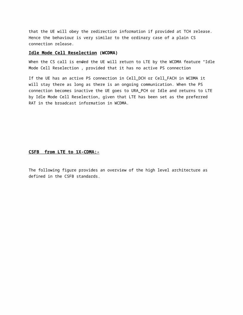
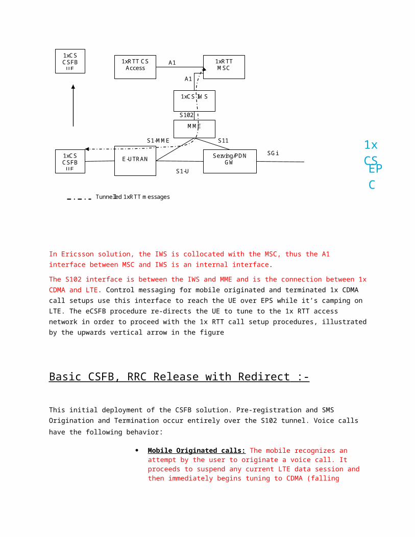
CSFB from LTE to 1X-CDMA:-
The following figure provides an overview of the high level architecture as defined in the CSFB standards.
In Ericsson solution, the IWS is collocated with the MSC, thus the A1 interface between MSC and IWS is an internal interface.
The S102 interface is between the IWS and MME and is the connection between 1x CDMA and LTE. Control messaging for mobile originated and terminated 1x CDMA call setups use this interface to reach the UE over EPS while it’s camping on LTE. The eCSFB procedure re-directs the UE to tune to the 1x RTT access network in order to proceed with the 1x RTT call setup procedures, illustrated by the upwards vertical arrow in the figure
Basic CSFB, RRC Release with Redirect :-
This initial deployment of the CSFB solution. Pre-registration and SMS Origination and Termination occur entirely over the S102 tunnel. Voice calls have the following behavior:
Mobile Originated calls: The mobile recognizes an attempt by the user to originate a voice call. It proceeds to suspend any current LTE data session and then immediately begins tuning to CDMA (falling back),
attaching and using normal CDMA procedures to originate a voice call. Note that this does not require any messaging across S102 or involvement of the IWS.
Mobile Terminated calls: The MSC recognizes that to page the mobile, it must do so via the IWS, rather than a normal BSC (as a result of pre-registration data). The page is delivered to the MME via the S102 tunnel and subsequently to the eNB and the UE. The UE proceeds to suspend any current LTE data session and then immediately begins tuning to CDMA (falling back), attaching and using normal CDMA procedures to respond to the page and accept the incoming call. The IWS is only involved in delivering the page message. No other messaging goes across the S102 link.
Characteristics:
Slower call set-up time because System Information needs to be fetched by the UE in the target RAN before call setup procedures can continue.
LTE: Circuit-Switched (CS) Fallback ConceptLTE: Circuit-switched (CS) fallback Concept1089 days ago 0 comments Categories: Blogger Tags:
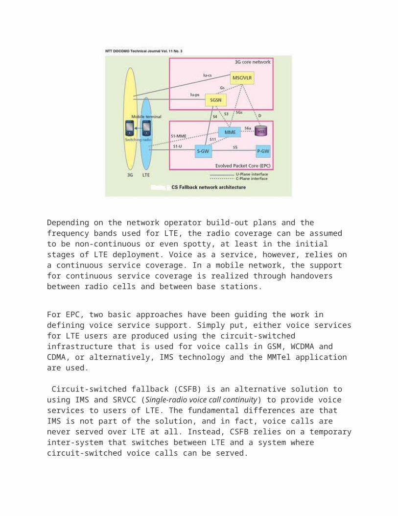
The LTE radio access has been designed to be optimized for IP-based services. This means that LTE has no support for dedicated channels optimized for voice calls. It is a packet-only access with no connection to the circuit-switched mobile core network. This is different to GSM, WCDMA and CDMA, which support both circuit- and packet-switched services and it naturally impacts the technical solution for how to deliver voice to LTE users.
Depending on the network operator build-out plans and the frequency bands used for LTE, the radio coverage can be assumed to be non-continuous or even spotty, at least in the initial stages of LTE deployment. Voice as a service, however, relies on a continuous service coverage. In a mobile network, the support for continuous service coverage is realized through handovers between radio cells and between base stations.
For EPC, two basic approaches have been guiding the work in defining voice service support. Simply put, either voice services for LTE users are produced using the circuit-switched infrastructure that is used for voice calls in GSM, WCDMA and CDMA, or alternatively, IMS technology and the MMTel application are used.
Circuit-switched fallback (CSFB) is an alternative solution to using IMS and SRVCC (Single-radio voice call continuity) to provide voice services to users of LTE. The fundamental differences are that IMS is not part of the solution, and in fact, voice calls are never served over LTE at all. Instead, CSFB relies on a temporary inter-system that switches between LTE and a system where circuit-switched voice calls can be served.
The solution is based on the fact that LTE terminals ‘register’ in the circuit-switched domain when powered and attaching to LTE. This is handled through an interaction between the MME and the MSC-Server in the circuit-switched network domain. There are then two use cases to consider – voice calls initiated by the mobile user or voice calls received by the mobile user:
1. If the user is to make a voice call, the terminal switches from LTE (system A) to a system with circuit-switched voice support (system B). Any packet-based services that happened to be active on the end-user device at this time are either handed over and continue to run in system B but on lower data speeds or suspended until the voice call is terminated and the terminal switches back to LTE again and the packet services are resumed. Which of these cases that apply will depend on the capabilities of system B.
2. If there is an incoming voice call to an end-user that is currently attached to LTE, the MSC-Server will request a paging in LTE for the specific user. This is done via the interface between the MSC-Server and the MME. The terminal receives the page, and temporarily switches from LTE to system B where the voice call is received. Once the voice call is terminated, the terminal switches back to LTE.
The main idea behind CS fallback is to allow UEs to camp on LTE and utilize the LTE for data services but reuse the GSM, WCDMA or CDMA network for circuit-switched voice services. To support CS fallback, there is a set of
modifications of existing procedures and also some additional CS fallback specific procedures added to EPS.
This article intends to illustrate the main principles of the CS fallback procedures by outlining an example of a CS fallback call.
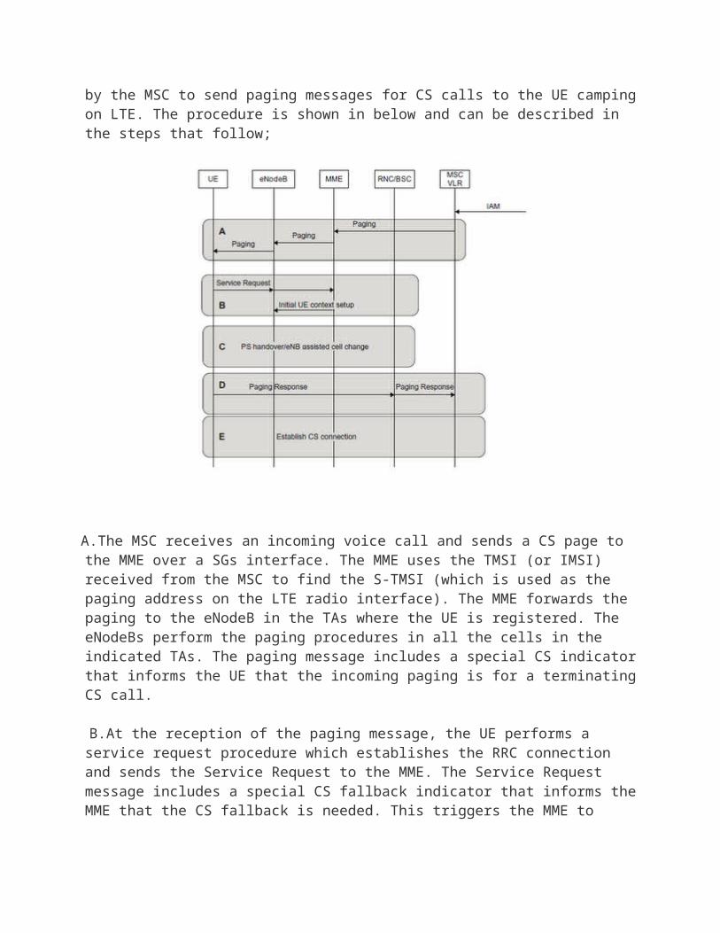
There are special additions to the attach and TA update procedures which activates an interface, called SGs, between the MME and the MSC. This interface is usedby the MSC to send paging messages for CS calls to the UE camping on LTE. The procedure is shown in below and can be described in the steps that follow;
A.The MSC receives an incoming voice call and sends a CS page to the MME over a SGs interface. The MME uses the TMSI (or IMSI) received from the MSC to find the S-TMSI (which is used as the paging address on the LTE radio interface). The MME forwards the paging to the eNodeB in the TAs where the UE is registered. The eNodeBs perform the paging procedures in all the cells in the indicated TAs. The paging message includes a special CS indicator that informs the UE that the incoming paging is for a terminating CS call.
B.At the reception of the paging message, the UE performs a service request procedure which establishes the RRC connection and sends the Service Request to the MME. The Service Request message includes a special CS
fallback indicator that informs the MME that the CS fallback is needed. This triggers the MME to activate the bearer context in the eNodeB with an indication to perform fallback to GERAN or UTRAN.
C.The eNodeB selects a suitable target cell, possibly by triggering the UE to send measurements on neighbour cells, and initiates a handover or cell change procedure. The selection between handover or cell change procedure is based on the target cell capabilities and is configured in the eNodeB.
D.After handover/cell change, the UE detects the new cell and establishes a radio connection and sends a page response to the MSC, via the target RAN.
E.When the page response arrives at the MSC, a normal mobile terminated call setup continues and the CS call is activated towards the UE.
The CS fallback specifications cover all necessary procedures to support fallback to GSM, WCDMA and 1xRTT for mobile originated and mobile terminating calls in both idle and active mode. The procedures for CS fallback are specified in 3GPP TS 23.272 [23.272].
Even though CS fallback was primarily introduced to support voice calls it also supports other CS services. In particular the support for SMS has been specified in such a way that it does not require the UE to switch to another radio interface. The UE can remain on LTE and still send and receive SMS. The SMS messages are tunnelled between the UE and the MSC through the
MME NAS signalling and the SGs interface.
Hello,
When the UE initiates a CS call in LTE and CSFB to wcdma after the call is ended, the umts instructs the ue to measure the lte freq.If the call is initiated in wcdma the release message does not contain the lte freq.This means that UMTS (RNC probably) knows that the call came from LTE. How? Which is the message (IE) ue sets to inform rnc that it came from lte?Could you tell me in which 3GPP TS is this procedure described (on utran side, the lte side I know: 23.272)
I found RRC CONNECTION REQUEST could set CSFB indicator IE but this is from 3GPP TS 25.331 V9.10 and the phone I used did not sent this IE but the network still knew to send the lte freq at call release.
Thank you!
incoincov2014-01-14, 11:14 PM
Hi mirc84,
do you have ISR (Idle mode signalling reduction) activated?
br!
incoincov2014-01-14, 11:28 PM
Hi again,
one more question: do you have PS HO in parallel with CS fallback?
incoincov2014-01-14, 11:42 PM
What about RAN container? RAN container is the information which comes originally from eNB that is encapsultated in a container to be deliverd to the RNC with some detailed information
mirc842014-01-18, 12:19 AM
1. No, I don't think we have ISR activated.2. Currently our network does not support PS HO but we have redirection.3.What about RAN container? RAN container is the information which comes originally from eNB that is encapsultated in a container to be deliverd to the RNC with some detailed informationCould you tell me what exactly are you talking about?
Extract from TS 25.413 CR1148• For MO call the UE indicates to the MSC in the 3GPP 24.008 CM SERVICE REQUEST message that this MO call is triggered due to CSFB.• For MT call, the UE that is subject to paging is camped on LTE, MME sends the SGs SERVICE REQUEST message to the MSC as part of the CSFB procedure.• For the case that the UE performs CSFB to a different MSC there are flags in the LAU message indicating CSFB MO or CSFB MT call.SA2 agreed CR0710 on 23.272 (S2-114637) at thier #87 meeting. The agreed CR transfers the knowledge of CSFB triggered call to UTRAN where it can be utilized to make a decision whether a UE at CS call release shall be pushed (back) to E-UTRAN or not.
The change proposed in this CR is to align with the agreed SA2 CR and transfer the knowledge of CSFB triggered call over Iu interface to UTRAN at release of the Iu CS connection, where it can be utilized to make a decision whether a UE shall be pushed (back) to E-UTRAN or not.It is proposed to add a new IE (end of CSFB) in the IU RELEASE COMMAND message that if included indicates that the Iu CS connection beeing released was initiated due to CSFB.
I found the changes in 24.008 V10.6.1 and the Iu release command with cause End of CSFB in 25.413 V10.6.0.But I could not find the IEs in the traces I took. Never the less the CSFB with Fast Return works fine. :)Maybe the RNC has a 6th sense like whirlpool products. :):)
Thanks for your time!
mirc842014-01-18, 12:59 AM
I want to add that in HEDEX (huawei) I found:The RNC first determines that a UMTS/LTE UE is a CSFB UE if it meets either of the following conditions:- PS handover with RELOCATION REQUEST containing IE “CS Fallback triggered” or a CSFB information IE whose value is “CSFB” of “CSFB High Priority”We do not have PS Handover, only redirection so this does not apply- RRC Connection Request message does not contain Pre-redirection IE. I did some calls and even if the mobile is calling without CSFB still the pre-redirection IE is not sent.- RRC connection Request with CSFB indicationI noticed that only IPhone 4 sends this indication. I didn’t notice it for any other phone (HTC one Samsung s3 s2LTE).- IU Release command with End of CSFB IE. RANAP_Iu_Release_Command does not contain this IE. I checked the RNC trace and CN INET trace.
ninjafine2014-01-18, 06:53 AM
Hello,
When the UE initiates a CS call in LTE and CSFB to wcdma after the call is ended, the umts instructs the ue to measure the lte freq.
If the call is initiated in wcdma the release message does not contain the lte freq.This means that UMTS (RNC probably) knows that the call came from LTE. How? Which is the message (IE) ue sets to inform rnc that it came from lte?Could you tell me in which 3GPP TS is this procedure described (on utran side, the lte side I know: 23.272)
I found RRC CONNECTION REQUEST could set CSFB indicator IE but this is from 3GPP TS 25.331 V9.10 and the phone I used did not sent this IE but the network still knew to send the lte freq at call release.
Thank you!
Hi Mirc84!Looks you are using 3G feature "Release with redirect to LTE".There is an option when it may triggers to LTE after CSFB at channel switch from DCH to FACH or at CS release from state Sp0 or state Speech.
mirc842014-01-20, 11:39 PM
Thanks ninjafine,
I know about the option. And it works fine.My problem is, whatever the switch setting, how does the RNC know that my mobile came from LTE so I can send the release message containing the UARFCN and get back to LTE.
In the end I noticed that the Location update contains some information. The reason why I was hard for me to seeit is that the Huawei RNC traces DOES NOT DECODE the hole message. Please see the attached picture. I found this while tracing the same call in INET, which showed me the hole information.
Now, I have another question. I noticed that on some networks, the first RRC connection request message cause is registration and after this the mobile does a location update. While on other networks, the first RRC connection request message cause is originating conv call. Why??
ninjafine2014-01-21, 06:08 AM
Thanks ninjafine,
I know about the option. And it works fine.My problem is, whatever the switch setting, how does the RNC know that my mobile came from LTE so I can send the release message containing the UARFCN and get back to LTE.
In the end I noticed that the Location update contains some information. The reason why I was hard for me to seeit is that the Huawei RNC traces DOES NOT DECODE the hole message. Please see the attached picture. I found this while tracing the same call in INET, which showed me the hole information.
Now, I have another question. I noticed that on some networks, the first RRC connection request message cause is registration and after this the mobile does a location update. While on other networks, the first RRC connection request message cause is originating conv call. Why??
Hi Mirc84! Don't see any attachment, anyway let's assume 2 scenarios:Call in LTE -> CSFB -> Call End in 3G -> 3G RRC request originating conv. call (no LAU),Call in LTE -> CSFB -> Call End in 3G -> 3G RRC request registration for LAU.
First scenario may happens e.g. for MO call. Any MO CS calls the UE fall backs towards the legacy network and discovers a "real" LA. This triggers a LA update before the call is set up. So you don't need LAU after call is ended in 3G.
Second scenario may indicate so calling Inter Working Function for CSFB (MO & MT).The IWF provides a number of advantages. At the most basic level it is an interface between the MME and the legacy CS network. At the same time it provides a VLR function where all the LTE UEs are registered against. This is done by creating a "virtual" LA and updating the HLR accordingly. Any MT calls are thus routed to the IWF. At the same time it eliminates the need for TA - LA planning as all TAs can point towards this one "virtual" LA.There is however one drawback with the IWF and that is that every call (MO & MT) requires a LAU before the call is set up. This adds approx. 1 to 2 seconds on the overall setup time. After call ends Ue discovers a "real" LA. This triggers a LA update.
Second scenario may also indicate classic MT CSFB. With the classic MT CSFB, there is an option when LAU is not performed and as such faster call setup times can be achieved. Here you need LAU after call is ended in 3G.
lq1822014-01-28, 10:01 AM
Hello,
When the UE initiates a CS call in LTE and CSFB to wcdma after the call is ended, the umts instructs the ue to measure the lte freq.If the call is initiated in wcdma the release message does not contain the lte freq.This means that UMTS (RNC probably) knows that the call came from LTE. How? Which is the message (IE) ue sets to inform rnc that it came from lte?Could you tell me in which 3GPP TS is this procedure described (on utran side, the lte side I know: 23.272)
I found RRC CONNECTION REQUEST could set CSFB indicator IE but this is from 3GPP TS 25.331 V9.10 and the phone I used did not sent this IE but the network still knew to send the lte freq at call release.
Thank you!What tool are you using to decode the L3 message? It might be that the tool does not decode that IE since it is quite a new IE. I know that this issue happened on TEMS and XCAL. Just ask your tool support.
mirc842014-02-01, 02:50 AM
What tool are you using to decode the L3 message? It might be that the tool does not decode that IE since it is quite a new IE. I know that this issue happened on TEMS and XCAL. Just ask your tool support.
We are using Huawei LMT for traces. We noticed that inside the Initial_UE_Message for LAU there are some fields which are not decoded which refer to CSFB MO/MT. Nevertheless, this message is transparent for RNC so it is not this one.Regarding the other IEs mentioned above it seems they are indeed not sent by the network (upgrade is necessary).
In the end we solve it together with Huawei suport. They are using a smart trick to recognize the CSFB calls.For us it seemed reasonable. We also re-tested and it seems that the phone does not send the pre-redirection IE if it is forced in UMTS. If it is not forced in UMTS, it actually sends the pre-redirection IE.
"Pre-redirection" is a optional IE, it is firstly imported in 3GPP R8.6.0,3GPP R9.4.0 protocol describes it as follows:-The way that recognize the CSFB users through this "Pre-redirection" IE should satisfy three conditions :- The UE supports LTE- UE sends RRC CONNECTION REQUEST with V860 Structure, but without "pre-redirection" IE.(we can think the user is redirected from LTE to UMTS ,if without "pre-redirection" IE )- UE can build CS service in 10s after building RRC connection successfully
Because the Pre-redirection is a optional IE, so some CSFB UEs don't support this way to be recognized, which results in CSFB identify failure. UL fast return is ineffective to the UE.
In future releases (and after network upgrade :)) there are other IE which could easily recognize the CSFB calls. Please see other posts for details. I hope this helps everybody.
ninjafine, thanks for the explanation, I'll look into IWF details these days. We actually found the problem, an incorrect mapping between LAC and TA in MME. :)
siyed802014-04-17, 12:14 AM
- RRC connection Request with CSFB indicationI noticed that only IPhone 4 sends this indication. I didn’t notice it for any other phone (HTC one Samsung s3 s2LTE).hi,can you confirm that the behavior occurs with an iphone 4. the iphone 4 does not support the LTE !!