Embed Size (px)
Citation preview

PDI Studio 5
Dayna Polstein
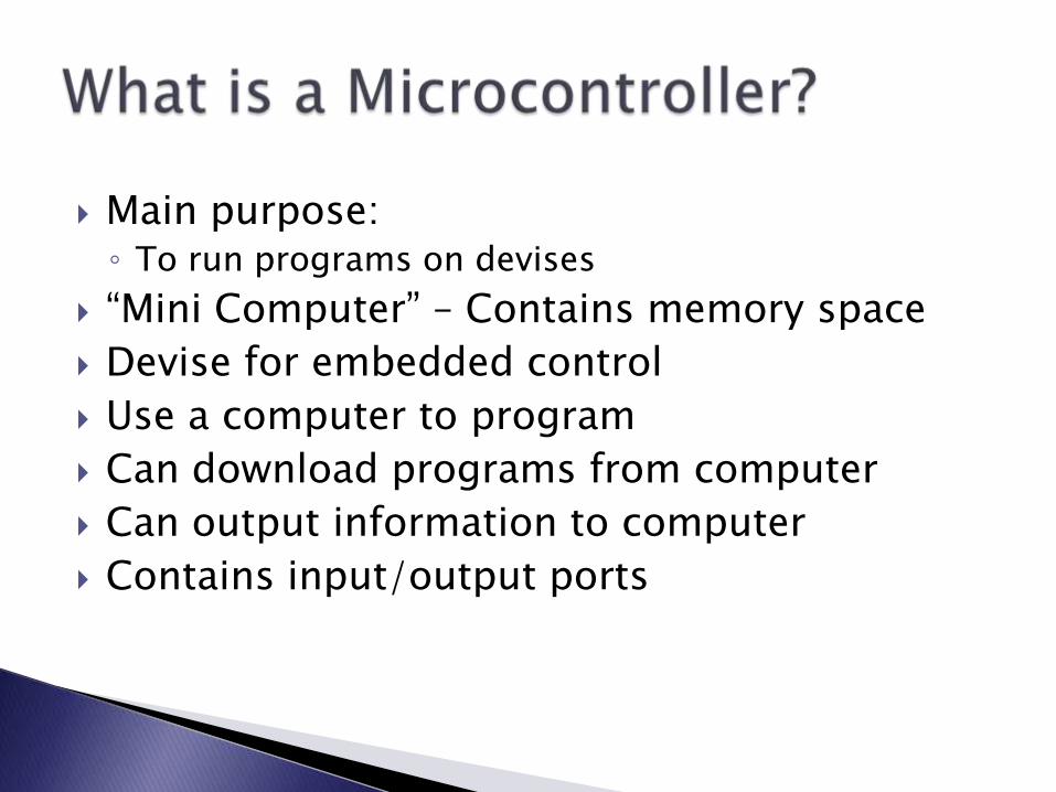
Main purpose:◦ To run programs on devises
“Mini Computer” – Contains memory space
Devise for embedded control
Use a computer to program
Can download programs from computer
Can output information to computer
Contains input/output ports

Everywhere!◦ Computers
◦ Remote controls
◦ Cell phones
◦ Cars (engine, antilock breaks, cruise control, etc.)
◦ Microwaves
◦ Dishwashers
◦ TVs
◦ DVD Players
◦ Almost every electronic with a user interface

Basic computer skills
C-programming
Some basic circuitry
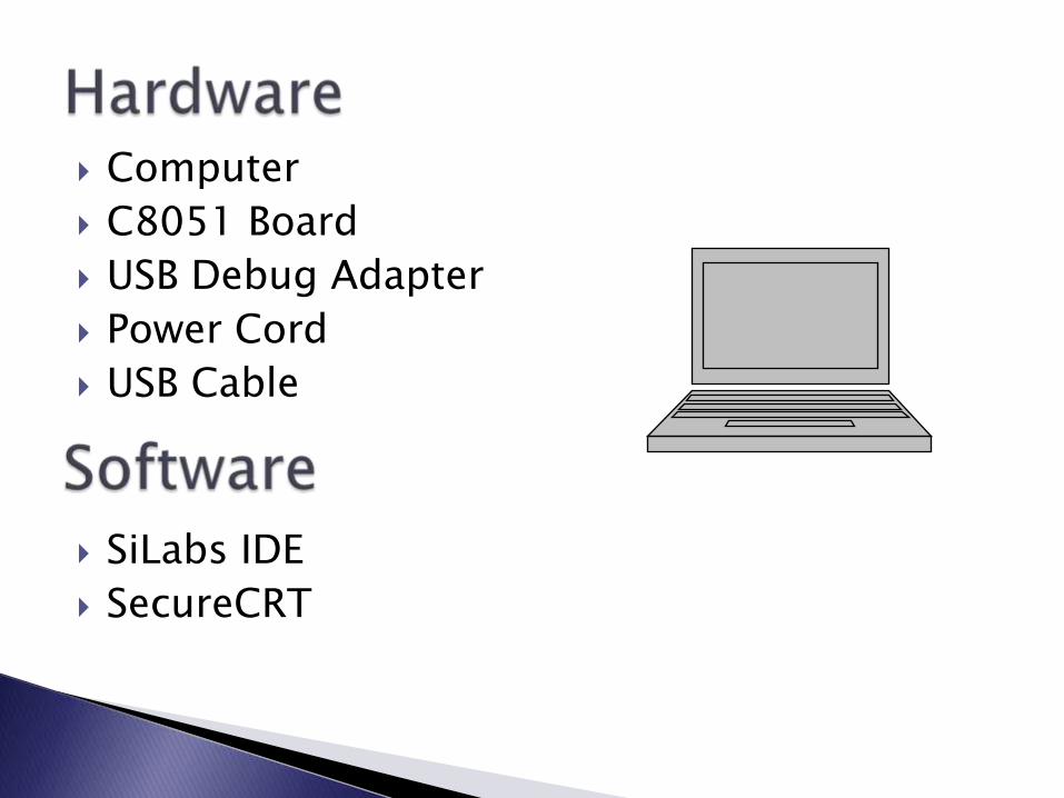
Computer
C8051 Board
USB Debug Adapter
Power Cord
USB Cable
SiLabs IDE
SecureCRT

1.

2. 3.
4.
Used For◦ Writing Programs
◦ Sending Programs to C8051
Programmed in C
Used For displaying text from:◦ Main Program
◦ Input

Be Careful with circuit◦ Circuit boards are very delecate
Only hold circuits by the edges◦ Do not touch anything metal
Before setting down:◦ Make sure rubber feet are in tact
◦ Make sure area is clean and dust-free
When storing:◦ Use anti-static bag and cushioned packaging
◦ Store at room temperature
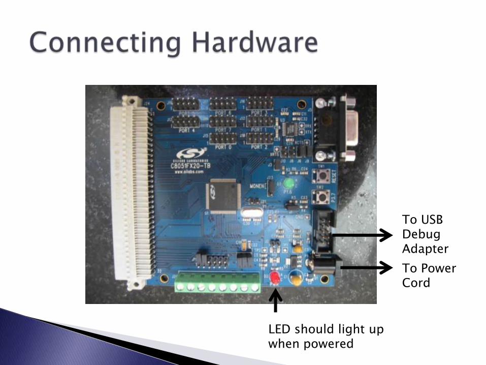
To USB Debug Adapter
To Power Cord
LED should light up when powered

USB to Computer
To power outlet
LEDs should light up when in use

1. Open SiLabs IDE
2. Go to File New File
3. Type in C Program Copy Sample Program:
#include <stdio.h>
main ()
{
printf(“PDI Studio 5/n");
}

4. Compile program by pressing the Assemble/Compile button on the toolbar or press Project Assemble/Compile File
5. Build program by pressing the Build/Make button on the toolbar or press Project Build/Make Project
Assemble/Compile Button
Build/Make Button
Note: If your program does not work, it will notify you at steps 4 and 5 and you will have to debug before attempting to connect

6. Go to Options Connection options and choose USB Debug Adapter and then OK
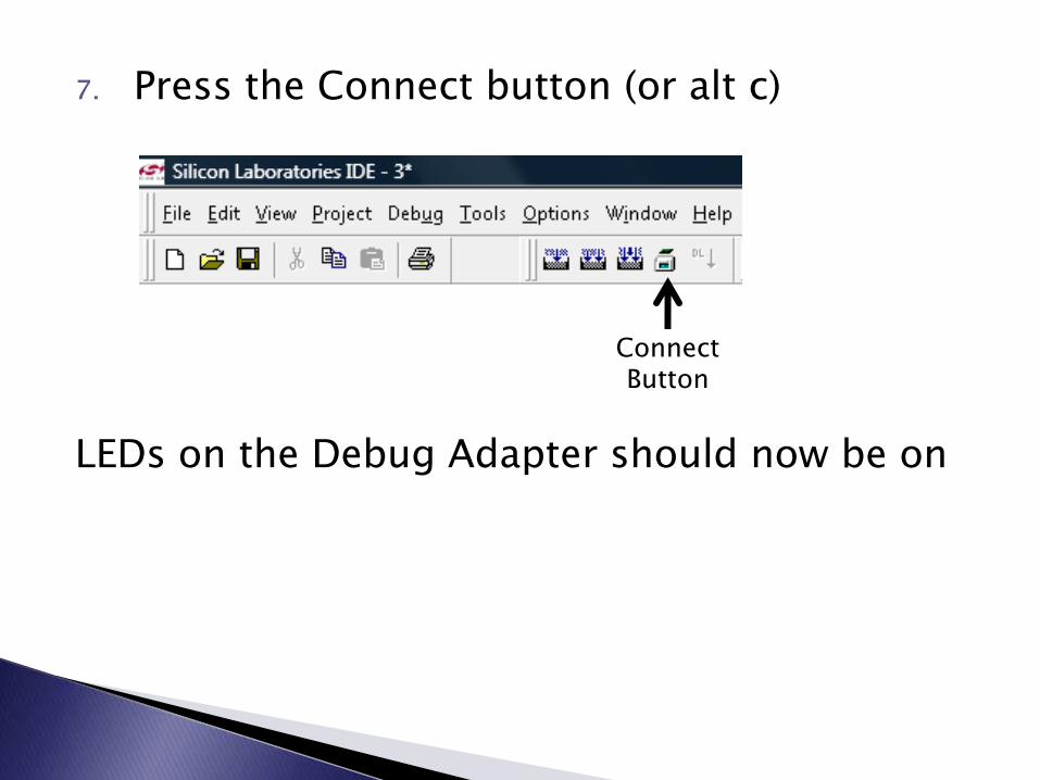
7. Press the Connect button (or alt c)
LEDs on the Debug Adapter should now be on
Connect Button

8. Press the Download code button
Download Code Button
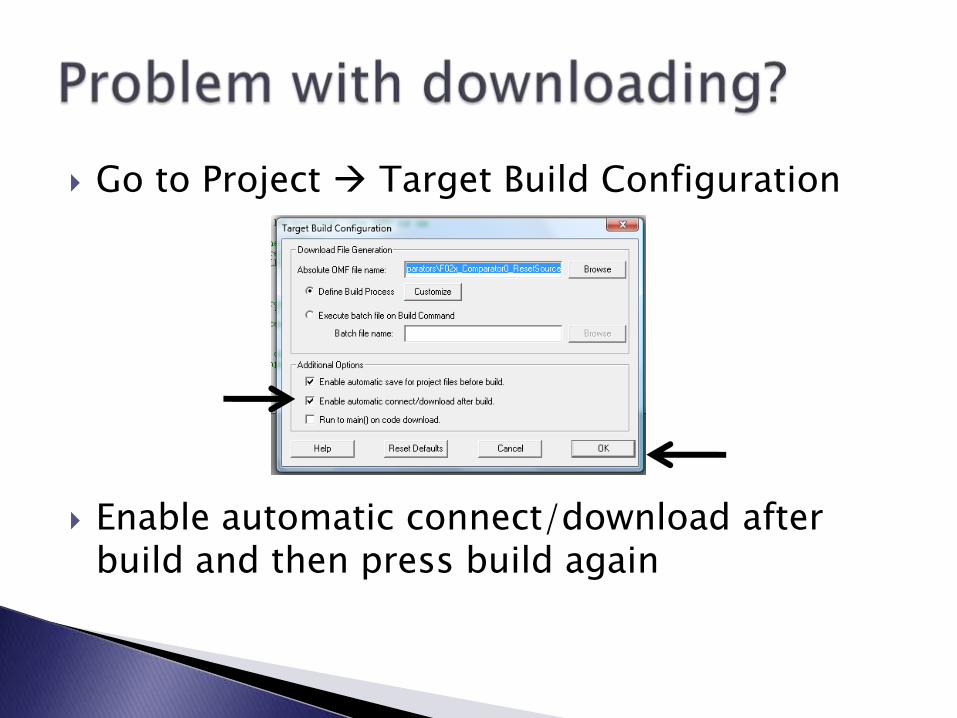
Go to Project Target Build Configuration
Enable automatic connect/download after build and then press build again

Go to C:\SiLabs\MCU\Examples\C8051F02x Click on the “Blinky” folder, and open the c
file in IDE Press on the green “go” button The green led on the board should start
blinking Press the red button for the program to stop Each program has a description of function
and reason for different lines Use these programs as guilds for your
programs
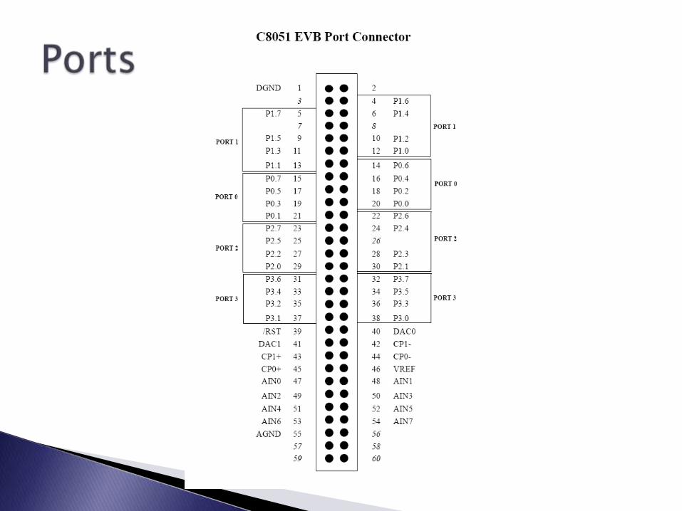

8 ports, 0 through 7
Each port is 1 byte (8 bits) wide
You can address to entire bytes or individual bits
Each port can be assigned as input or output
C8051 will read the ports as◦ 0 volts as false
◦ +3 volts as true

Setting by bit (one of eight bits of the port)◦ To assign b7 of port 0 :
sbit bit7 = P0^7;
bit7 = 1;
Set as Input◦ Port 3 pin 7
P3MDout &= ~0x80;
P3 | = 0x80; *****
Set as Output◦ Port 2 pin 2
P2MOUT |= 0x04
For individual bits, first read entire port, then use masking to determine value of bit
Describe Masking Here
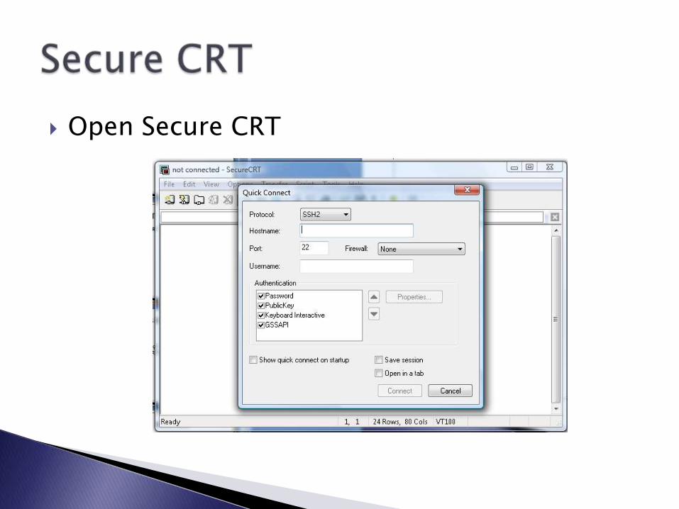
Open Secure CRT

Change settings and connect (try different com numbers) **

Right click on Serial-COM3 and select “Session Options…”

Click on emulation, change the scrollbackbuffer to 32000, and press ok.

Make a new project and file in IDE (save as 384test.c
Copy this program:
#include "c8051.h"
int main(){
Sys_Init();printf("\n\n\ntesting...\n");printf("done for now...\n");while(1);
}
Compile and build the code
Connect and download code
Start the code
Text should display on Secure CRT window ***
Embedded Control Course Materials http://litec.rpi.edu/course.php
IDE Software: http://litec.rpi.edu/Postings/UsingSiLabsIDE.html
C8051 User Guide http://litec.rpi.edu/Postings/C51_User_Guide.pdf
C8051 Manual: http://litec.rpi.edu/Postings/C8051F02xRev1_4.pdf

Timers
A/D Converter
C programming?