Embed Size (px)
Citation preview
Bachelor of Science (Honours) (Architecture)
Project 1:
Fettuccine Test
Module:
Building Structures (ARC 2523)
Group Members:
Farah Farhanah Kassim (0317534)
Felicia Novera (0316206)
Johan Syahriz bin Muhaiyar (0316115)
Muhammad Faridzul Fikri bin Jeffry (0311836)
Renee Lim Wei Fen (0311016)
Table of Contents
1.0 Introduction

1.1 Aims and Objectives
1.2 Project Scope
2.0 Methodology
3.0 Precedent Study
3.1 History
3.2 Structural Details
4.0 Materials and Equipment
4.1 Materials
4.2 Equipment
5.0 Design and Structure Analysis
5.1 Bridge Design 1
5.2 Bridge Design 2
5.3 Bridge Design 3
5.4 Bridge Design 4
5.5 Bridge Design 5
6.0 Conclusion
7.0 Appendix
8.0 References
1.0 INTRODUCTION
1.1 Aims and Objectives
The objectives of this project are as follows

To develop student’s understanding of tension and compressive strength of construction materials
To develop student’s understanding of force distribution in a truss To design a perfect truss bridge which fulfils the following criteria:
High level of aesthetic value Minimal construction material
1.2 Project Scope
In a group, you are required to design and construct a fettucine bridge of 750mm clear span and maximum weight of 200g. These requirements are to be met, or else it may result in reduction of grade. The bridge will be then tested to fail.
Other than aesthetic value, the design of the bridge must be of high efficiency, i.e. using the least material to sustain the higher load. The efficiency of the bridge is given as following;
In order to achieve higher efficiency, you need to analyse and evaluate each of the following items.
Material strength By adopting appropriate method, determine the strength of fettucine, i.e.
tension and compression strength By knowing the strength of fettucine, you will be able to determine
which members to be strengthened Structural analysis of the truss
Perform detailed structural analysis of the truss Identify critical members Strengthened the critical members if necessary
2.0 METHODOLOGY
In a group of five, we were assigned to build and design a truss bridge with fettuccine as sole material of the bridge.

Before designing and building the bridge, first we were required to have a sample of existing truss bridge. The Deep River Camelback Truss Bridge has been chosen as the precedent study object for this project. The purpose of conducting a precedent study is to gain an understanding on how a truss design might affect the stability and the strength of the bridge.
As fettuccine is never a material for construction, we had to test its strength beforehand. Different types of glue were also being tested for its adhesive strength.
Second, we started on building our fettucine bridge. The first bridge we build referred to Waddell “A” Truss and it was able to withstand load as heavy as 3 kg. The bridge itself weighs around 150 grams with 750mm bridge span and 54mm gap span.The second bridge referred to Arch Bridge and was able to withstand load just until 1.5kg.The third test-bridge too referred to Waddell “A” Truss, but we added some supports on some part of the bridge and it was able to withstand load until 5kg.The fourth test-bridge was similar to the third bridge. We added support on the parts that seemed to be broken in the third bridge and it was able to withstand load as heavy as 4.8kg.
After obtaining and consolidating the data we received from the testing of the previous bridges, we settled on a centre reinforced Waddell “A” Truss design with reinforced bracing supports for our final bridge.
3.0 PRECEDENT STUDY
In order to achieve a proper understanding of the truss bridge system, we carried out a precedent study on a currently existing truss bridge; The Deep River Bridge in North Carolina,USA.
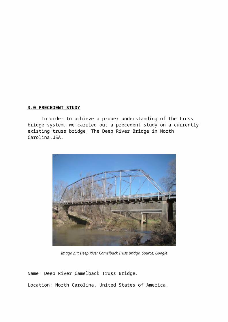
Image 2.1: Deep River Camelback Truss Bridge. Source: Google
Name: Deep River Camelback Truss Bridge.
Location: North Carolina, United States of America.
Largest Span: 160.1 ft.
Total length: 365.2 ft.
Inside width: 14.8 ft., one lane
Design: Eight-panel, pin-connected Camelback truss with steel stringer/timber approaches.
Year Built: 1901
Materials: Steel
Type of Truss: Camelback truss
3.1 History
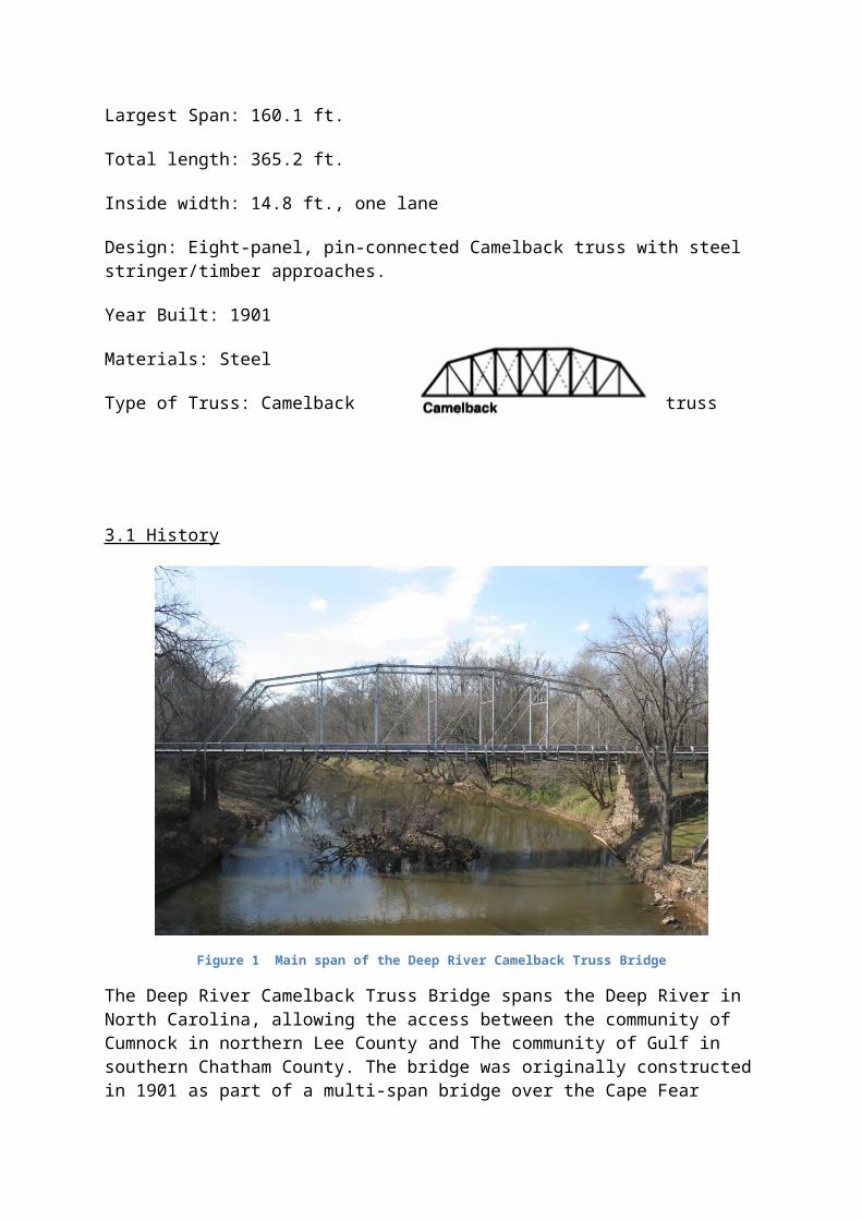
Figure 1 Main span of the Deep River Camelback Truss Bridge
The Deep River Camelback Truss Bridge spans the Deep River in North Carolina, allowing the access between the community of Cumnock in northern Lee County and The community of Gulf in southern Chatham County. The bridge was originally constructed in 1901 as part of a multi-span bridge over the Cape Fear River at Lillington. The bridge was dissembled after a span of the bridged collapsed in December 1930 in order for a new bridge to be erected. In 1932, one of the spans was rebuilt at the site over the Deep River to replace another wooden bridge that was burned in 1929. Ever since 1833, bridges had always been used as connecting access above the Deep River.
In 1979, the bridge was marked as one among thirty-five bridges that are eligible for the National Register as significant examples of metal truss engineering technology in the state starting from 1880 to 1935, as well as for associations with transportation improvements in the beginning of the twentieth century. The Deep River Camelback Truss Bridge which was also named Truss Bridge #155, is one of four surviving camelback truss bridges in North Carolina. On east of Truss Bridge #155, a new concrete bridge spanning the Deep River was completed in 1992 by the Department of Transportation. The older bridge then had its ownership transferred to the Deep River Park Association and will be preserved as part of the group’s Rails-Trails route under development.
The camelback configuration originated from the Pratt truss which explains the similarity between the two designs. With the exception of two extra panels, the arrangement of the diagonal structural members of the Camelback is identical to that of the Pratt truss. Two center panels of the Camelback have double diagonals that cross to form an “X”. The most significant and distinguishing feature of a Camelback is the top chord, the Deep River Truss Bridge’s top chord for example has three sections to it. The center section is straight while the left and right sections angle down to the frontal posts. This gives Camelback truss’s top chords four angles while the semi-curve of the top chord allows the bridge to span greater distances using fewer materials.
3.2 Structural Details
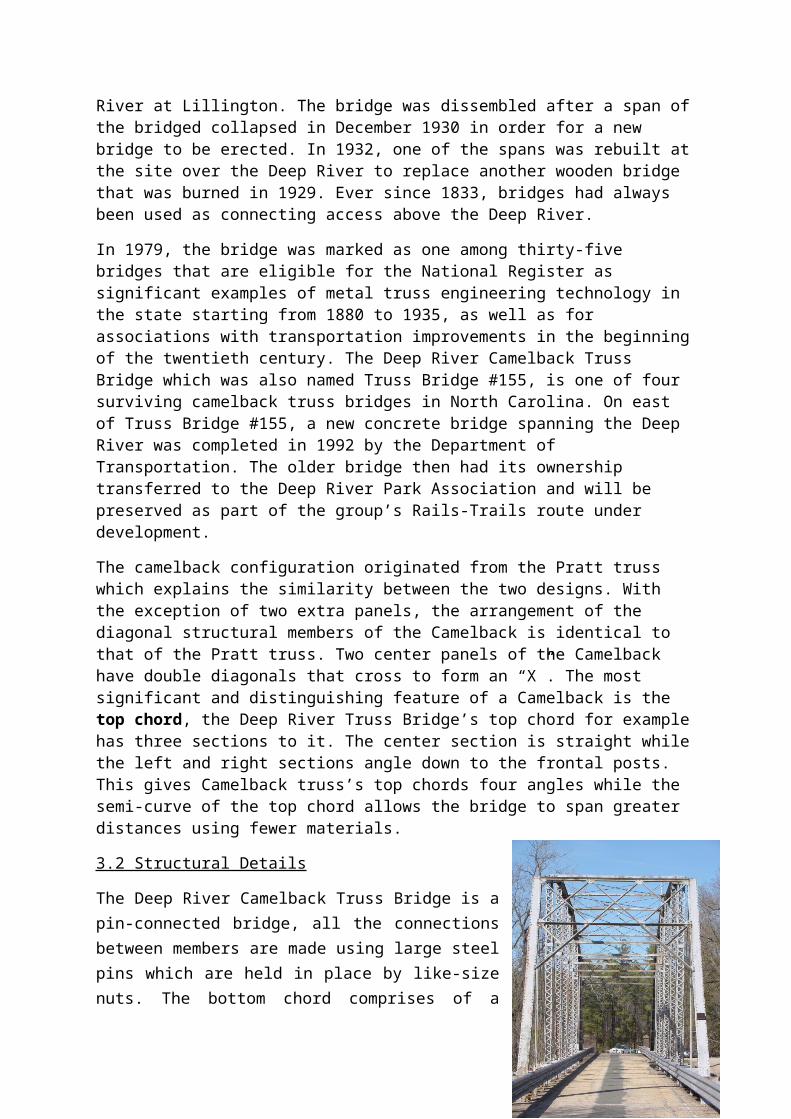
The Deep River Camelback Truss Bridge is a pin-connected bridge, all the connections between members are made using large steel pins which are held in place by like-size nuts. The bottom chord comprises of a series of eyebars which are more similar to a diagonal member as opposed to a single beam. The vertical members use “built-up” beams, which are two lengths of steel “stitched” together to form one single beam. This is accomplished by riveting together short pieces of steel across the beam in a “zigzag” pattern. The top chord and front posts are also “built-up” but employ steel plates called batons instead.
The extent of the rehabilitation of this remains unclear but modifications throughout the years include paving over with asphalt the wooden deck. Modern guardrails supported by their own beams as opposed to being bolted onto the bridge’s structural members were added. A few of the diagonals have also been reinforced with parallel cables.
Truss Analysis
A comparative study using a Pratt truss which Camelback truss is a derivative of.
Conclusion: In both cases, the total load = 100. The camelback truss emulates the exact same formula however it’s top chord does not stay parallel with the bottom chord. This creates a lighter structure without losing strength, less dead loads at ends and more concentrated strength at center.
Figure 2 Portal shot of the Deep River Camelback Truss Bridge.
Figure 3 The decking below the bridge.Figure 4 Pratt Truss.
Figure 4 Pratt Truss with centered load. Figure 6 Pratt Truss with spread load.
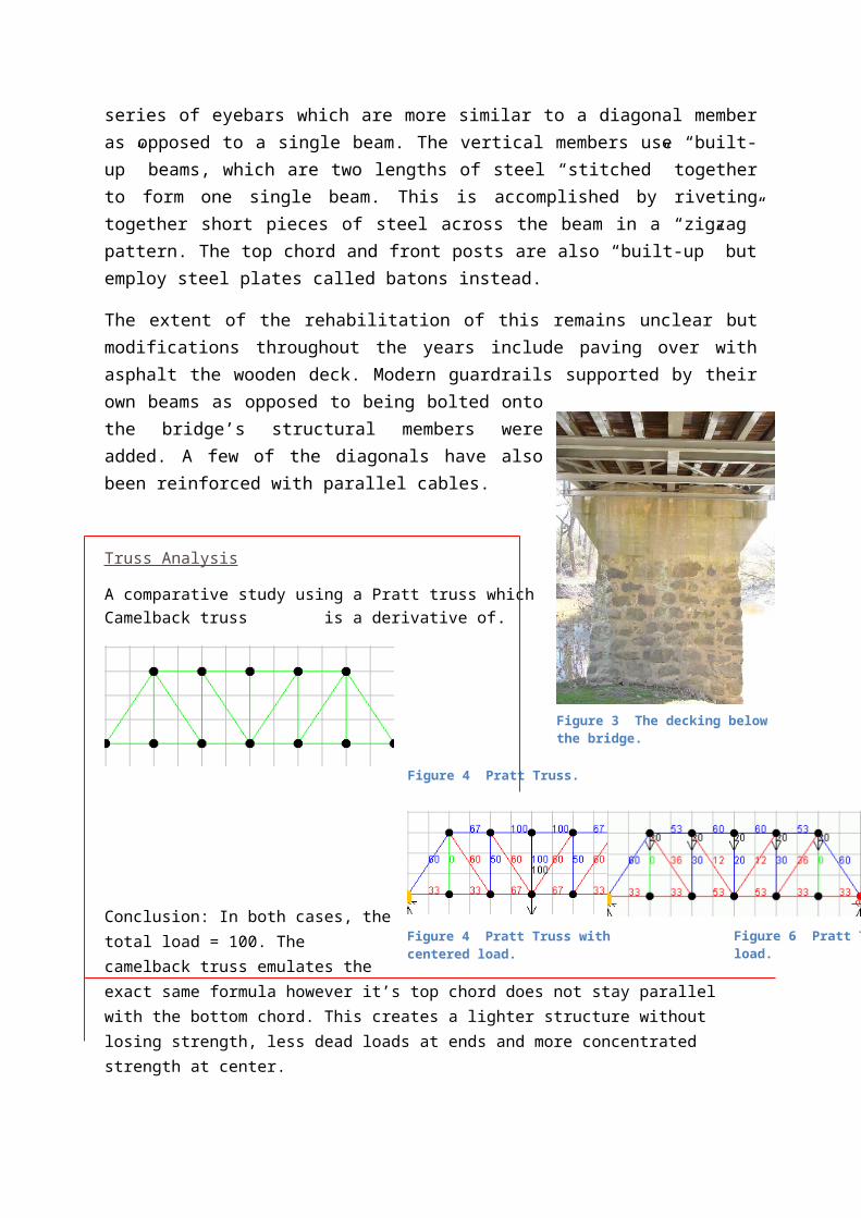
Figure 5 A pinned connection between the lower chord and a vertical member.
Figure 6 The same connection as viewed from above. Note the added steel cable.
Figure 7 An upper chord/front post connection.

4.0 MATERIALS AND EQUIPMENT
4.1 Materials
SAN REMO FETTUCCINE No. of layers
Length (cm)
Span (cm)
Vertical (g)
Horizontal (g)
1 20 10 130 802 20 10 890 5203 20 10 1000 9004 20 10 1700 1550
SUPER GLUE DESCRIPTION
Mostly used as it sticks just right and does not deteriorate the fettuccine as fast as 3 second glue.
3 SECOND GLUE DESCRIPTION
It sticks right away and strong, but it also deteriorates the material fast.
DUNLOP GLUE DESCRIPTION

Was used to increase the flexibility of the bridge so it doesn’t break straight away, but crack slowly
instead.
4.2 Equipment
PEN KNIFE / CUTTER DESCRIPTION
Was used to cut the pasta / fettuccine
S HOOK DESCRIPTION
Was used as connector between the bridge and the pail
PAIL DESCRIPTION
Was used to hold loads
WATER DESCRIPTION
Was used as loads

KITCHEN BALANCE DESCRIPTION
Was used to weigh the bridge and loads
5.0 DESIGN AND STRUCTURE ANALYSIS
5.1 Bridge Design 1
In the first design, we designed our bridge in according to the Pratt truss manner. In which the bridge is made of trusses that have vertical web members to take tension forces and with angled braces to take compression. As a start we made the bridge exactly at 750mm which gave us a span of less than 750mm. The weight of the bridge only took up 150 grams. At the end of the bridge testing, the bridge could only hold a load of 3.3 kilograms. The efficiency of the bridge was 72% the bridge broke on most of the members instead of the joints. Which concludes that the members were not strong enough as torsion occurred.
Weight of bridge: 150g
Clear span of bridge: 650mm
Load sustained: 3.3
Efficiency: 72%
Tension Compression
Breakage point
Load (g) Checked Remarks100 / -200 / -300 / -600 / -900 / -
1200 / -1500 / -1800 / -2100 / -2400 / -2700 / -3000 / -3300 x *broken*

Solution:
1. The members of the bridge should be strengthened by multiplying the number of fettuccine in each member.
2. Besides that, the bridge should have horizontal membersat the top of the structure to prevent torsion from occurring.
5.2 Bridge Design 2
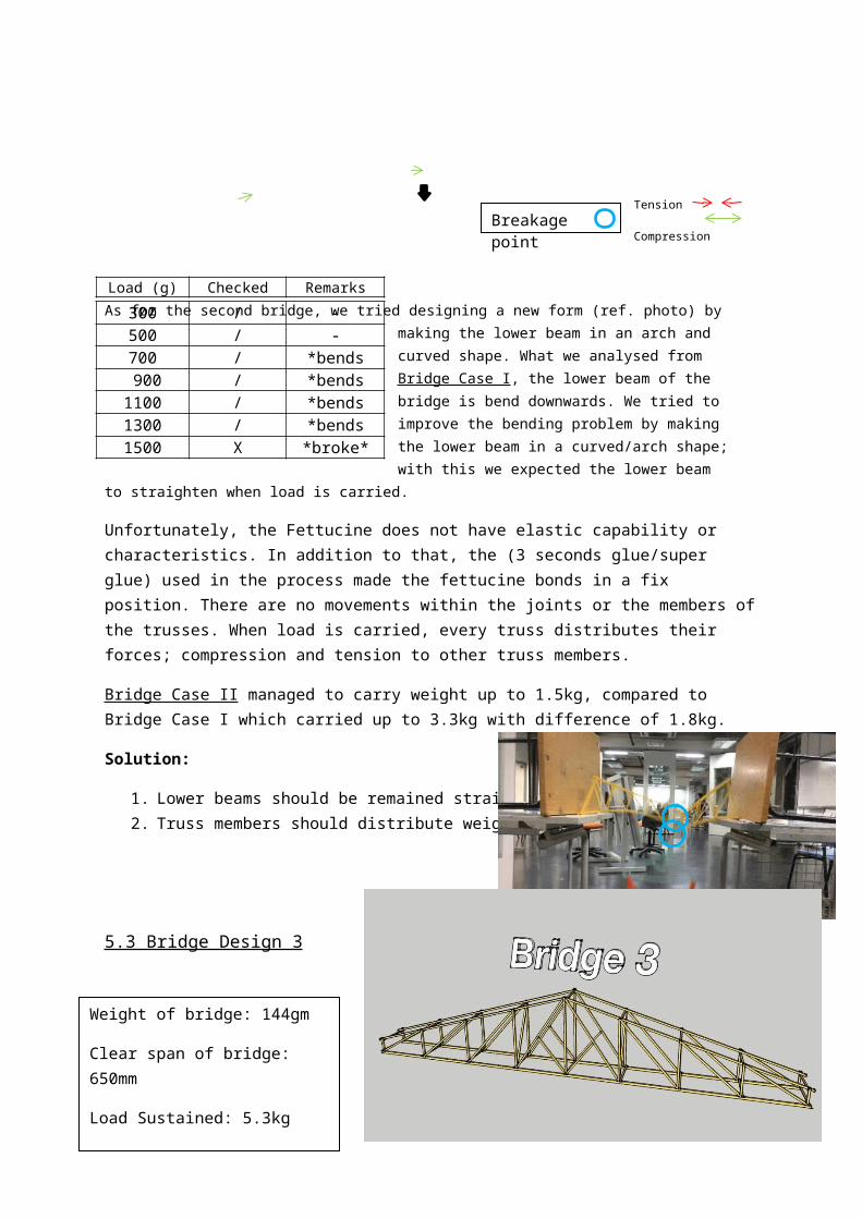
As for the second bridge, we tried designing a new form (ref. photo) by making the lower beam in an arch and curved shape. What we analysed from Bridge Case I, the lower beam of the bridge is bend downwards. We tried to improve the bending problem by making the lower beam in a curved/arch shape; with this we expected the lower beam to straighten when load is carried.
Unfortunately, the Fettucine does not have elastic capability or characteristics. In addition to that, the (3 seconds glue/super glue) used in the process made the fettucine bonds in a fix position. There are no movements within the joints or the members of the trusses. When load is carried, every truss distributes their forces; compression and tension to other truss members.
Weight of bridge: 200g
Clear span of bridge: 700mm
Load sustained: 1.5kg
Efficiency: 11%
Breakage point Tension Compression
Load (g) Checked Remarks
300 / -500 / -700 / *bends 900 / *bends1100 / *bends1300 / *bends1500 X *broke*

Bridge Case II managed to carry weight up to 1.5kg, compared to Bridge Case I which carried up to 3.3kg with difference of 1.8kg.
Solution:
1. Lower beams should be remained straightened.2. Truss members should distribute weight evenly.
5.3 Bridge Design 3
Design has not reached the required 750mm span but is well within the weight limit at 144gm out of the 200gm. The center member supporting the hook for load testing broke in the middle of testing due to insufficient lamination, however it did not affect other members of the bridge and we quickly and simply replaced it with a double laminated member to continue testing. Aesthetic value is less than bridge 2 but efficiency rate improved significantly with this change in design.
Solution :
1. Reinforce area around the concentrated point load by adding more layers of lamination as well as adding more horizontal and cross bracing to center.
Weight of bridge: 144gm
Clear span of bridge: 650mm
Load Sustained: 5.3kg
Efficiency: 35.4%
Breakage point Tension Compression
Load (g) Checked Remarks
300 / *no changes1200 / *no changes2100 / *no changes 2700 / *bends3700 / *bends4700 / *bends5300 X *Broke*

2. Diverting load to spread away from center and reducing the concentration of applied load by changing the direction of center diagonal bracings on both sides.
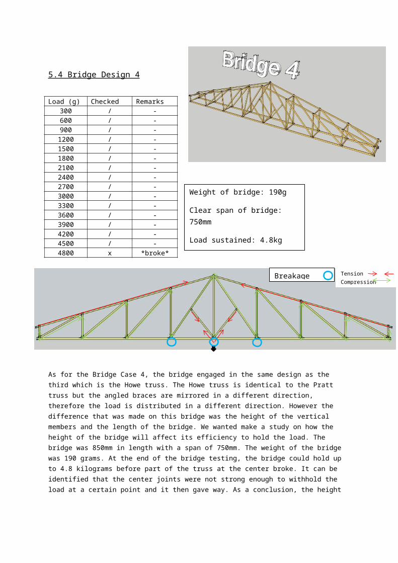
5.4 Bridge Design 4
As for the Bridge Case 4, the bridge engaged in the same design as the third which is the Howe truss. The Howe truss is identical to the Pratt truss but the angled braces are mirrored in a different direction, therefore the load is distributed in a different direction. However the difference that was made on this bridge was the height of the vertical members and the length of the bridge. We wanted make a study on how the height of the bridge will affect its efficiency to hold the load. The bridge was 850mm in length with a span of 750mm. The weight of the bridge was 190 grams. At the end of the bridge testing, the bridge could hold up to 4.8 kilograms before part of the truss at the center broke. It can be identified that the center joints were not strong enough to withhold the load at a certain point and it then gave way. As a conclusion, the height did play a role in the structure as it could carry more loads then the one before.
Solution:
1. The joints at the center should be improved by making sure the fettuccine does not detach easily from its joints.
Weight of bridge: 190g
Clear span of bridge: 750mm
Load sustained: 4.8kg
Efficiency: 121%
Figure 9 Center support on one side completely broke off along with the horizontal center member.
Figure 8 Horizontal member broke off due to insufficient lamination
Load (g) Checked Remarks300 / -600 / -900 / -
1200 / -1500 / -1800 / -2100 / -2400 / -2700 / -3000 / -3300 / -3600 / -3900 / -4200 / -4500 / -4800 x *broke*
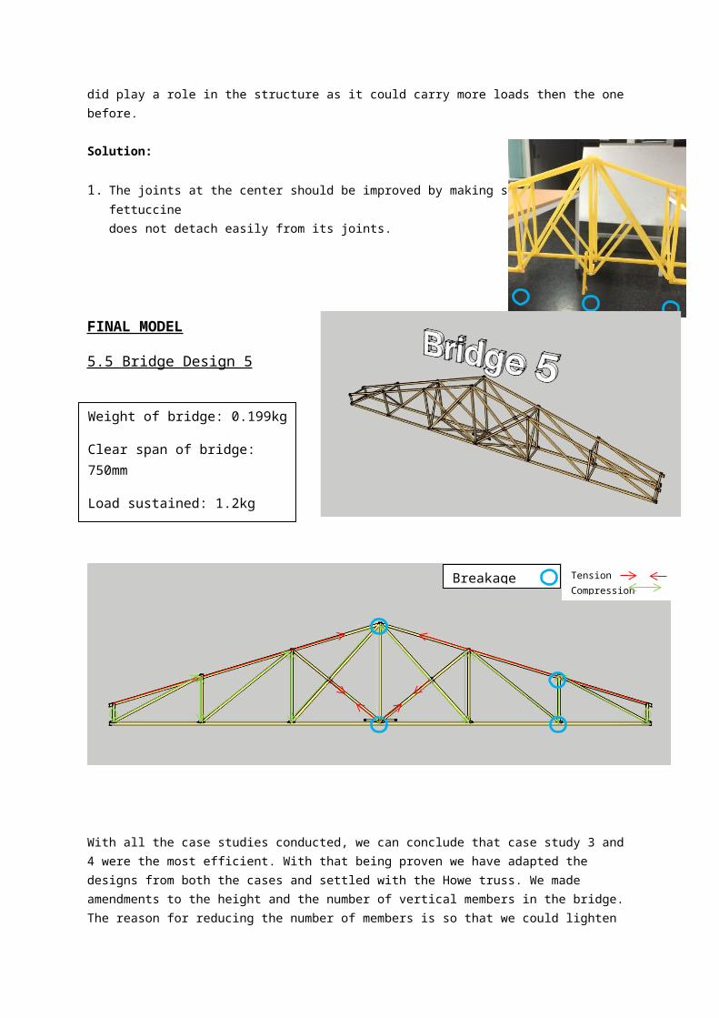
FINAL MODEL
5.5 Bridge Design 5
With all the case studies conducted, we can conclude that case study 3 and 4 were the most efficient. With that being proven we have adapted the designs from both the cases and settled with the Howe truss. We made amendments to the height and the number of vertical members in the bridge. The reason for reducing the number of members is so that we could lighten the weight of the bridge as we were emphasizing on strengthening the joints through bracing. The bridge was 850mm in length with a given span of 750mm. The weight of the entire bridge added up to 199 grams which did not exceed the requirement of the project. Unfortunately, the bridge could only carry a load of 1.2 kilograms. It was observed that the unexpected end of the bridge broke because the load was not transferred equally due to the center vertical member that was not placed at a 90 degree. As a conclusion from this final test, angles of members in trusses place an important role in the whole truss system.
Solution:
1. To place members of fettuccine at 90 degrees to ensure an equal load transfer throughout the whole bridge.
2. Reinforce area around the concentrated point load by adding more layers of lamination as well as adding more horizontal and cross bracing in between members.
Weight of bridge: 0.199kg
Clear span of bridge: 750mm
Load sustained: 1.2kg
Efficiency: 10%
Tension Compression
Breakage point

6.0 CONCLUSION
Analyzing all the cases in general, it is visible which is the most efficient amongst the 5.
Firstly, we should assume all these cases act simultaneously. Secondly, if the member carries more force, it tends to break easily.
For example in case 5, one of the diagonal members exerts about 926.3 kN of force. It will break easily and will be less sufficient.
In case 3, columns supporting 150kN or less will break first due to the top members transferring 734 kN force and it is not distributed evenly.
In case 2, column carrying 210kN will break first but if compared with case 4, case 4 will collapse before case 2 and case 1 due to heavy loads being supported by small horizontal members.
If the compression is big, the members will be prove to buckling while high tension will cause the members to snap. From all the 5 cases, case 2 will be the most efficient in our opinion because it has better load distribution among the members.
7.0 APPENDIX
8.0 REFERENCES
Boon, G. (2015). Garrett's Bridges » Pratt Truss. Garrettsbridges.com. Retrieved 6 May 2015, from http://www.garrettsbridges.com/design/pratt-truss
Sites.google.com,. (2015). Deep River Camelback Truss Bridge - Matthew B Ridpath. Retrieved 6 May 2015, from https://sites.google.com/site/matthewbridpath/bridges-and-highways-1/truss-bridges/deep-river-camelback-truss-bridge
Pghbridges.com,. (2015). Bridge Basics - A Spotter's Guide to Bridge Design. Retrieved 7 May 2015, from http://pghbridges.com/basics.htm


![[DRAFT, PRE-FINAL OR FINAL] REPORT - OECD](https://img.pdfslide.us/doc/110x75/5ec770f8c7c9f9670a3f7375/-draft-pre-final-or-final-report-.jpg)