Embed Size (px)
Citation preview

Sarfaraz husain MAULANA AZAD NATIONAL URDU UNIVERSITY
Mobile no =+91- 818481318
www.facebook .com/pasha.don143
MCA 2nd year student
Displays
Emissive display -- convert electrical energy into light - Cathode ray tube (CRT) - Flat panel CRT - Plasma panels (gas-discharge display) - Thin-film electroluminescent (EL) display - Light-emitting diodes Non-Emissive display -- optical effect: convert sunlight or
light from other source into graphic patterns. - Liquid-crystal device (LCD) – flat panel - Passive-matrix LCD - Active-matrix LCD
Monochrome Cathode Ray Tube (CRT)
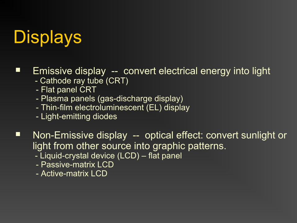
Cathode Ray – beam of electrons - emitted by an electron gun - accelerated by a high positive voltage near the face of the tube - forced into a narrow stream by a focusing system - directed toward a point on the screen by the magnetic field generated by the deflection coils - hit onto the the phosphor-coated screen - phosphor emits visible light, whose intensity depends on the number of electrons striking on the screen
Cathode
Focusingsystem
Horizontal& vertical deflection
Electron gun
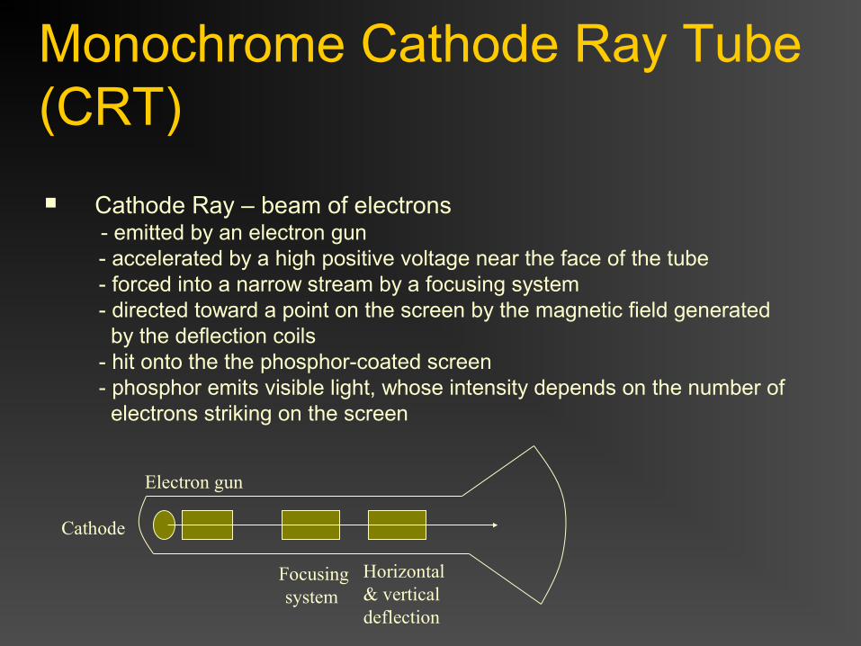
Properties of the CRT Phosphor Persistence (PP) - the light output decays exponentially with time. - a phosphor’s persistence is defined as the time from the removal of excitation to the moment of decaying the light to one-tenth of its original intensity - low persistence -> good for animation - high persistence -> good for static picture with high complexity - typical range: 10ms – 60ms
Refresh rate (RR) - number of times per second the image is redrawn (e.g., 60 or higher)
Critical fusion frequency (CFF) - the refresh rate above which a picture stops flickering and becomes steady
longer PP -> lower CFF required
Properties of the CRT
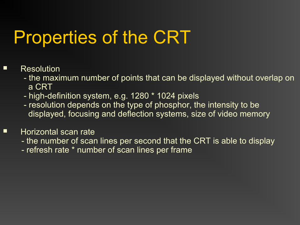
Resolution - the maximum number of points that can be displayed without overlap on a CRT - high-definition system, e.g. 1280 * 1024 pixels - resolution depends on the type of phosphor, the intensity to be displayed, focusing and deflection systems, size of video memory
Horizontal scan rate - the number of scan lines per second that the CRT is able to display - refresh rate * number of scan lines per frame
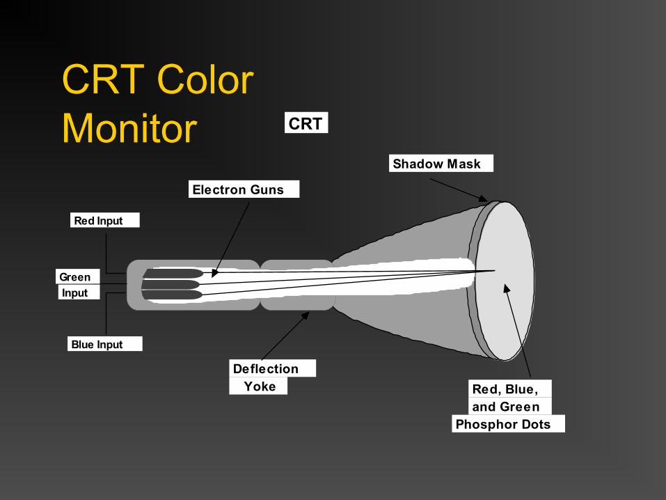
CRT Color Monitor
Electron Guns
Red Input
Green
Input
Blue Input
Deflection Yoke
Shadow Mask
Red, Blue, and Green
Phosphor Dots
CRT
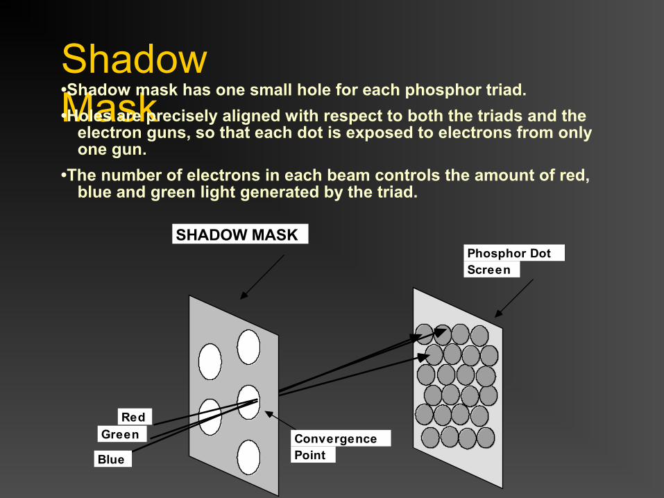
Shadow Mask
SHADOW MASK
Red
Green
Blue
Convergence Point
Phosphor Dot Screen
•Shadow mask has one small hole for each phosphor triad.
•Holes are precisely aligned with respect to both the triads and the electron guns, so that each dot is exposed to electrons from only one gun.
•The number of electrons in each beam controls the amount of red, blue and green light generated by the triad.
Properties of the CRT
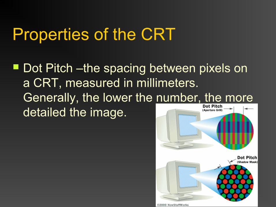
Dot Pitch –the spacing between pixels on a CRT, measured in millimeters. Generally, the lower the number, the more detailed the image.
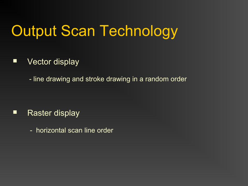
Output Scan Technology
Vector display
- line drawing and stroke drawing in a random order
Raster display - horizontal scan line order
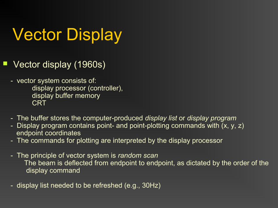
Vector Display
Vector display (1960s) - vector system consists of: display processor (controller), display buffer memory CRT
- The buffer stores the computer-produced display list or display program - Display program contains point- and point-plotting commands with (x, y, z) endpoint coordinates - The commands for plotting are interpreted by the display processor
- The principle of vector system is random scan The beam is deflected from endpoint to endpoint, as dictated by the order of the display command
- display list needed to be refreshed (e.g., 30Hz)
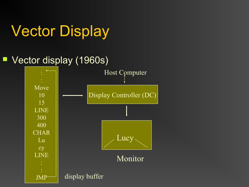
Vector Display
Vector display (1960s)
::
Move1015
LINE300400
CHARLucy
LINE::
JMP
Display Controller (DC)
Monitor
Lucy
Host Computer
display buffer
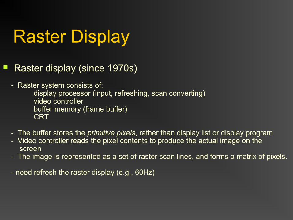
Raster Display
Raster display (since 1970s) - Raster system consists of: display processor (input, refreshing, scan converting) video controller buffer memory (frame buffer) CRT
- The buffer stores the primitive pixels, rather than display list or display program - Video controller reads the pixel contents to produce the actual image on the screen - The image is represented as a set of raster scan lines, and forms a matrix of pixels. - need refresh the raster display (e.g., 60Hz)
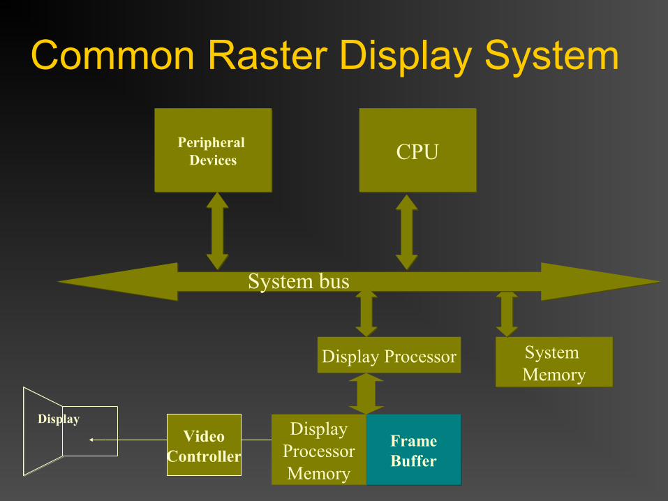
Common Raster Display System
CPUCPU
System MemorySystem Memory
Peripheral Devices
Peripheral Devices
FrameBufferFrameBuffer
Display
System bus
DisplayProcessorMemory
Display Processor
VideoController
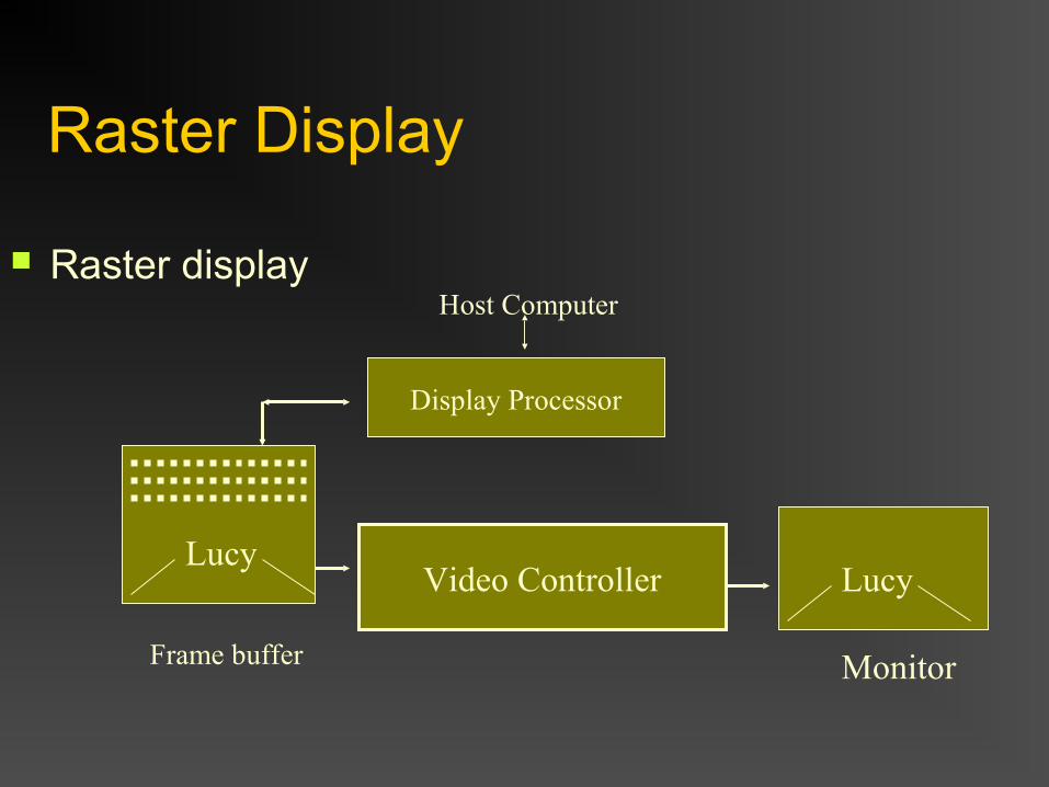
Raster Display
Raster display
Display Processor
Monitor
Lucy
Host Computer
Frame buffer
Video ControllerLucy
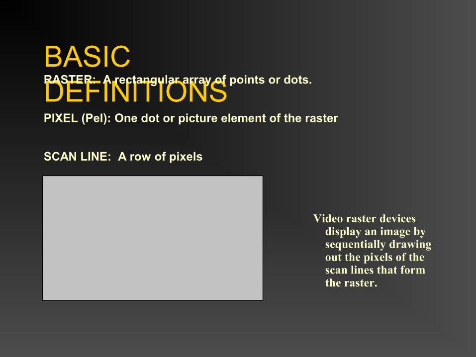
BASIC DEFINITIONSRASTER: A rectangular array of points or dots.
PIXEL (Pel): One dot or picture element of the raster
SCAN LINE: A row of pixels
Video raster devices display an image by sequentially drawing out the pixels of the scan lines that form the raster.
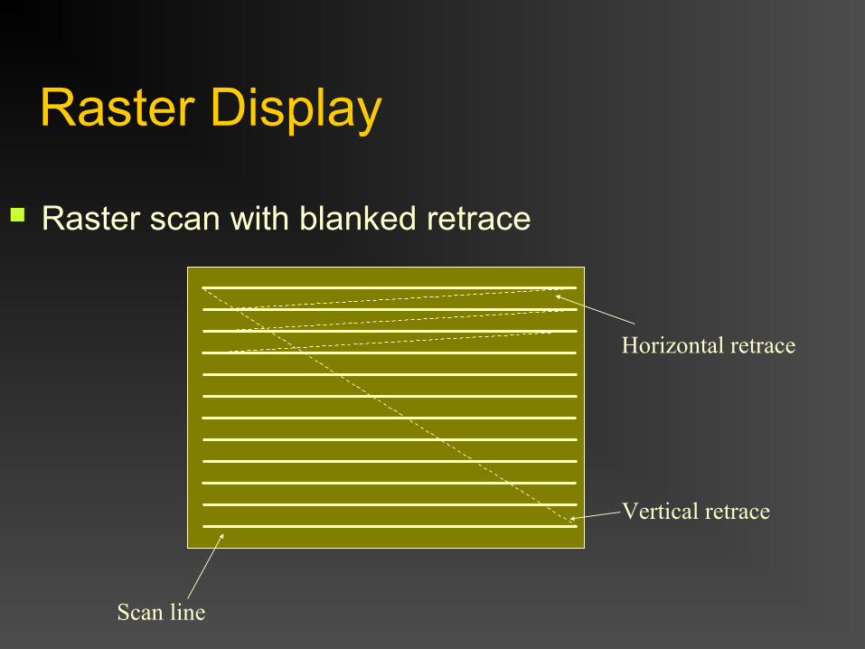
Raster Display
Raster scan with blanked retrace
Scan line
Vertical retrace
Horizontal retrace
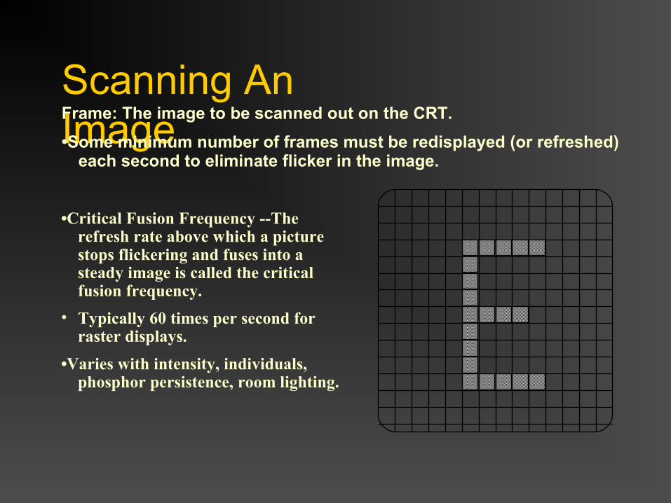
Scanning An ImageFrame: The image to be scanned out on the CRT.
•Some minimum number of frames must be redisplayed (or refreshed) each second to eliminate flicker in the image.
•Critical Fusion Frequency --The refresh rate above which a picture stops flickering and fuses into a steady image is called the critical fusion frequency.
• Typically 60 times per second for raster displays.
•Varies with intensity, individuals, phosphor persistence, room lighting.
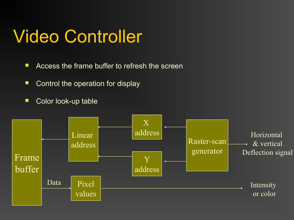
Video Controller Access the frame buffer to refresh the screen
Control the operation for display
Color look-up table
Linear address
X address
Yaddress
Raster-scangenerator
Framebuffer
Pixelvalues
Horizontal & vertical
Deflection signal
Data Intensity or color
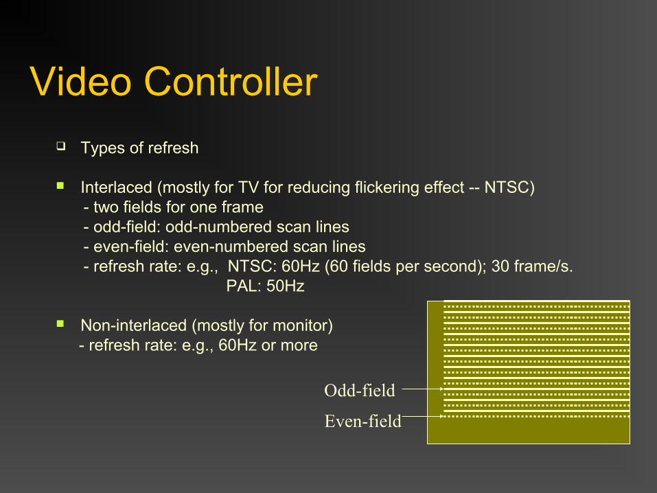
Video Controller Types of refresh
Interlaced (mostly for TV for reducing flickering effect -- NTSC) - two fields for one frame - odd-field: odd-numbered scan lines - even-field: even-numbered scan lines - refresh rate: e.g., NTSC: 60Hz (60 fields per second); 30 frame/s. PAL: 50Hz
Non-interlaced (mostly for monitor) - refresh rate: e.g., 60Hz or more
Odd-field
Even-field
Display ProcessorAlso called either a Graphics Controller or Display CoProcessor
Specialized hardware to assist in scan converting output primitives into the frame buffer.
Fundamental difference among display systems is how much the display processor does versus how much must be done by the graphics subroutine package executing on the general-purpose CPU.
Frame Buffer
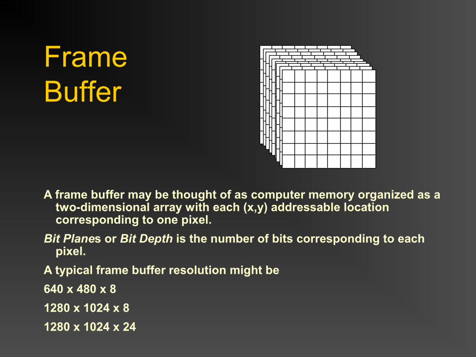
A frame buffer may be thought of as computer memory organized as a two-dimensional array with each (x,y) addressable location corresponding to one pixel.
Bit Planes or Bit Depth is the number of bits corresponding to each pixel.
A typical frame buffer resolution might be
640 x 480 x 8
1280 x 1024 x 8
1280 x 1024 x 24
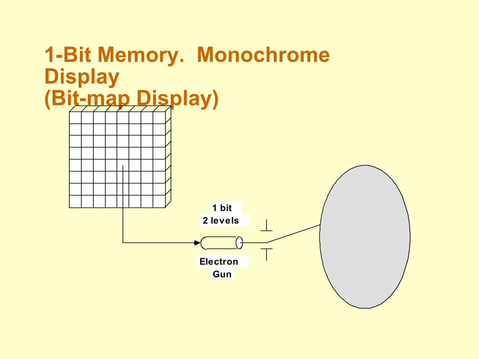
1-Bit Memory. Monochrome Display(Bit-map Display)
Electron Gun
1 bit 2 levels
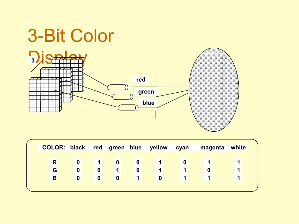
3-Bit Color Display3
red
green
blue
COLOR: black red green blue yellow cyan magenta white
R G B
0 0 0
1 0 0
0 1 0
0 0 1
1 1 0
0 1 1
1 0 1
1 1 1
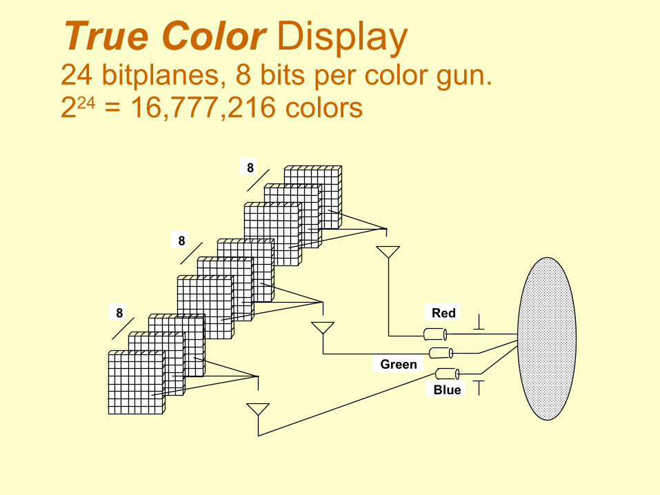
True Color Display24 bitplanes, 8 bits per color gun. 224 = 16,777,216 colors
Green
Red
Blue
8
8
8
Color Look-up Table
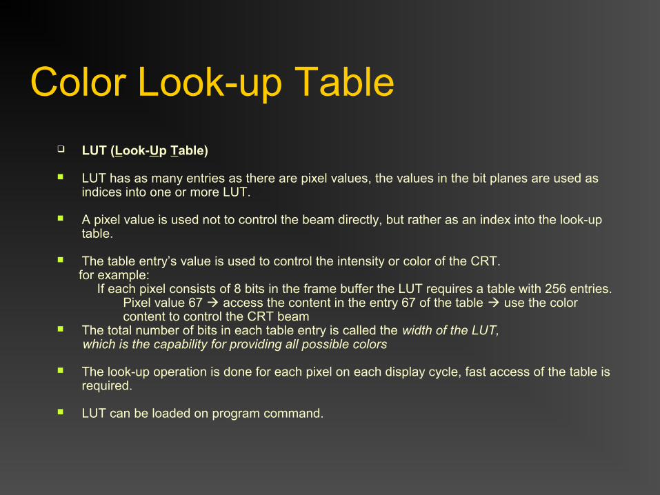
LUT (Look-Up Table)
LUT has as many entries as there are pixel values, the values in the bit planes are used as indices into one or more LUT.
A pixel value is used not to control the beam directly, but rather as an index into the look-up table.
The table entry’s value is used to control the intensity or color of the CRT. for example: If each pixel consists of 8 bits in the frame buffer the LUT requires a table with 256 entries. Pixel value 67 access the content in the entry 67 of the table use the color content to control the CRT beam The total number of bits in each table entry is called the width of the LUT, which is the capability for providing all possible colors
The look-up operation is done for each pixel on each display cycle, fast access of the table is required.
LUT can be loaded on program command.
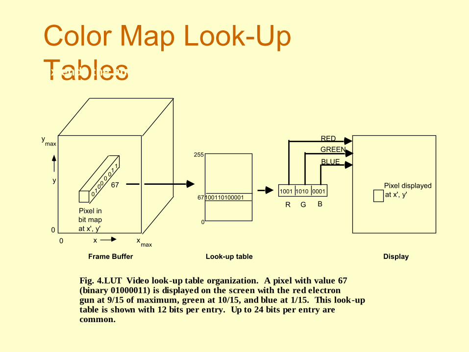
Color Map Look-Up TablesExtends the number of colors that can be displayed by a given
number of bit-planes.
Fig. 4.LUT Video look-up table organization. A pixel with value 67 (binary 01000011) is displayed on the screen with the red electron gun at 9/15 of maximum, green at 10/15, and blue at 1/15. This look-up table is shown with 12 bits per entry. Up to 24 bits per entry are common.
0100
001
1
67
100110100001
0
67
255
1001 1010 0001
R G B
RED
GREEN
BLUE
Pixel displayedat x', y'
Pixel inbit mapat x', y'
0 x
0
y
xmax
maxy
Frame Buffer Look-up table Display
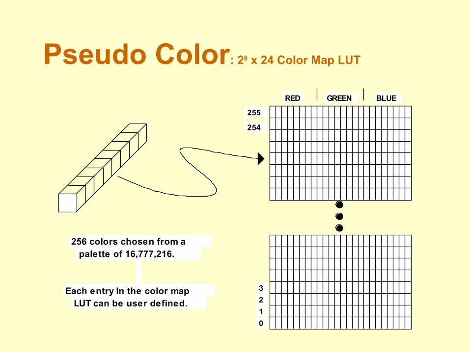
Pseudo Color: 28 x 24 Color Map LUT
0
1
2
3
254
255
RED GREEN BLUE
256 colors chosen from a palette of 16,777,216.
Each entry in the color map LUT can be user defined.
Could be used to define 256 shades of green or
64 shades each of red, blue, green and
white, etc.
Color Look-up Table
The number of the bit planes in the frame buffer determines the number of colors displayable on the screen simultaneously
The width of the LUT determines the number of possible colors that we can choose from (also called the color palette)
Example: 8 bit planes 28 or 256 colors can be displayed simultaneously
A LUT width of 12 bits color palette consists of 212 colors in all
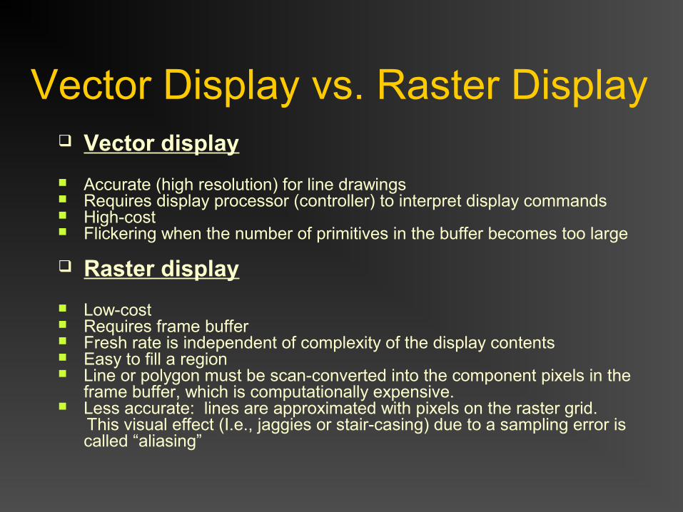
Vector Display vs. Raster Display Vector display
Accurate (high resolution) for line drawings Requires display processor (controller) to interpret display commands High-cost Flickering when the number of primitives in the buffer becomes too large Raster display
Low-cost Requires frame buffer Fresh rate is independent of complexity of the display contents Easy to fill a region Line or polygon must be scan-converted into the component pixels in the
frame buffer, which is computationally expensive. Less accurate: lines are approximated with pixels on the raster grid. This visual effect (I.e., jaggies or stair-casing) due to a sampling error is
called “aliasing”