MODELSDIRECT-FIRED
YPC-FA-12SC THRU YPC-FZ-19S STEAM-FIRED
YPC-ST-14SC THRU YPC-ST-19S
(DIRECT-FIRED UNIT SHOWN)
27679A
YPC TWO-STAGE DIRECT-FIRED AND STEAM-FIRED ABSORPTION CHILLER-HEATERS
RENEWAL PARTS Supersedes: 155.17-RP3 (1107) Form 155.17-RP3 (113)
Issue Date: January 31, 2013

JOHNSON CONTROLS2
FORM 155.17-RP3 ISSUE DATE: 1/31/2013
This equipment is a relatively complicated apparatus. During installation, operation maintenance or service, individuals may be exposed to certain components or conditions including, but not limited to: refrigerants, materials under pressure, rotating components, and both high and low voltage. Each of these items has the potential, if misused or handled improperly, to cause bodily injury or death. It is the obligation and respon-sibility of operating/service personnel to identify and recognize these inherent hazards, protect themselves, and proceed safely in completing their tasks. Failure to comply with any of these requirements could result in serious damage to the equipment and the property in
IMPORTANT!READ BEFORE PROCEEDING!
GENERAL SAFETY GUIDELINES
which it is situated, as well as severe personal injury or death to themselves and people at the site.
This document is intended for use by owner-authorized operating/service personnel. It is expected that these individuals possess independent training that will en-able them to perform their assigned tasks properly and safely. It is essential that, prior to performing any task on this equipment, this individual shall have read and understood this document and any referenced mate-rials. This individual shall also be familiar with and comply with all applicable governmental standards and regulations pertaining to the task in question.
SAFETY SYMBOLSThe following symbols are used in this document to alert the reader to specific situations:
Indicates a possible hazardous situation which will result in death or serious injury if proper care is not taken.
Indicates a potentially hazardous situa-tion which will result in possible injuries or damage to equipment if proper care is not taken.
Identifies a hazard which could lead to damage to the machine, damage to other equipment and/or environmental pollu-tion if proper care is not taken or instruc-tions and are not followed.
Highlights additional information useful to the technician in completing the work being performed properly.
External wiring, unless specified as an optional connection in the manufacturer’s product line, is not to be connected inside the control cabinet. Devices such as relays, switches, transducers and controls and any external wiring must not be installed inside the micro panel. All wiring must be in accor-dance with Johnson Controls’ published specifications and must be performed only by a qualified electrician. Johnson Controls will NOT be responsible for damage/problems resulting from improper connections to the controls or application of improper control signals. Failure to follow this warn-ing will void the manufacturer’s warranty and cause serious damage to property or personal injury.

JOHNSON CONTROLS 3
FORM 155.17-RP3 ISSUE DATE: 1/31/2013
CHANGEABILITY OF THIS DOCUMENT
In complying with Johnson Controls’ policy for con-tinuous product improvement, the information con-tained in this document is subject to change without notice. Johnson Controls makes no commitment to update or provide current information automatically to the manual owner. Updated manuals, if applicable, can be obtained by contacting the nearest Johnson Controls Service office.
Operating/service personnel maintain responsibility for the applicability of these documents to the equipment. If there is any question regarding the applicability of
these documents, the technician should verify whether the equipment has been modified and if current litera-ture is available from the owner of the equipment prior to performing any work on the chiller.
CHANGE BARSRevisions made to this document are indicated with a line along the left or right hand column in the area the revision was made. These revisions are to technical in-formation and any other changes in spelling, grammar or formatting are not included.

JOHNSON CONTROLS4
FORM 155.17-RP3 ISSUE DATE: 1/31/2013
NOMENCLATUREThe model number denotes the following characteristics of the unit:
Modification Level* A = Molybdate inhibitor (7/93) B = 122 Copper Alloy Tubes in Abs., Cond., & LTG (4/94) C = Smart Purge system (1/97) D = ASHRAE 90.1 (10/03) Tube Type S = Standard tubes A = Tube Option “A” X = Special tubes
Hot Water Heater S = Standard heater H = High temperature heater C = Cooling only
Electrical 17 = 208-3-60 28 = 230-3-60 46 = 460-3-60 50 = 380-3-50
Size 12SC thru 19S
Heat Source FN = Direct Fired (with Power Flame burner) (Natural gas) FD = Direct Fired (with Natural gas / No. 2 Oil) FO = Direct Fired (with No. 2 Oil) FX = Direct Fired (with Other Fuels) FL = Direct Fired (with Natural gas w/ Low NOx FGR) FP = Direct Fired (with Natural gas w/ Low NOx FGR / No. 2 Oil)
FE = Direct Fired (with Weishaupt burner) (Natural gas) FZ = Direct Fired (with Natural gas / No. 2 Oil) FB = Direct Fired (with No. 2 Oil) FA = Direct Fired (with Other Fuels) FR = Direct Fired (with Natural gas w/ Low NOx FGR) FC = Direct Fired (with Natural gas w/ Low NOx FGR / No. 2 Oil) ST = Steam Heat
Model = York ParaFlow Chiller
YPC – FN – 13S – 46 – H – S – D
* Modification “B” contains Modification “A” Modification “C” contains Modifications “A” and “B”

JOHNSON CONTROLS 5
FORM 155.17-RP3 ISSUE DATE: 1/31/2013
LIST OF FIGURES
TABLE OF CONTENTS
FIGURE 1 - Major and System Control Component Location For Direct-Fired Units (Exhaust End) ........................7FIGURE 2 - Major and System Control Component Location For Direct-Fired Units (Panel Side) ...........................8FIGURE 3 - Major and System Control Component Location For Direct-Fired Units (Burner End) ..........................9FIGURE 4 - Major and System Control Component Location For Steam-Fired Units (Steam Inlet End)................10FIGURE 5 - Major and System Control Component Location For Steam-Fired Units (Panel Side) ........................ 11FIGURE 6 - Major and System Control Component Location For Steam-Fired Units (Opposite End) ...................12FIGURE 7 - Major and System Control Component Location For Steam-Fired Units (Opposite Panel Side) ........13FIGURE 8 - Main Control Panel Components 1 ......................................................................................................16FIGURE 9 - Main Control Panel Components 2 ......................................................................................................17FIGURE 10 - Main Control Panel Components 3 ....................................................................................................18FIGURE 11 - Electrical Connections (Thermistor) ...................................................................................................20FIGURE 12 - Electrical Connections (Transducer) ..................................................................................................21FIGURE 13 - 2 Pump Units .....................................................................................................................................24FIGURE 14 - 3 Pump Units .....................................................................................................................................26FIGURE 15 - Single-Ended Pump ...........................................................................................................................35FIGURE 16 - Double-Ended Pump .........................................................................................................................35FIGURE 17 - Pump, Single-Ended Exploded View .................................................................................................37FIGURE 18 - Pump, Double-Ended Exploded View 1 .............................................................................................38FIGURE 19 - Pump, Double-Ended Exploded View 2 .............................................................................................39
MAJOR AND SYSTEM CONTROL COMPONENT LOCATION FOR DIRECT-FIRED UNITS ................................7
MAJOR AND SYSTEM CONTROL COMPONENT LOCATION FOR STEAM-FIRED UNITS ..............................10
MAIN CONTROL PANEL ........................................................................................................................................14
POWER PANEL COMPONENTS ...........................................................................................................................23
SYSTEM CONTROL COMPONENTS ....................................................................................................................29
VALVES ...................................................................................................................................................................30
FLOAT VALVES ......................................................................................................................................................32
STEAM CONTROL VALVES AND ACTUATORS ...................................................................................................32
PUMPS ....................................................................................................................................................................33
TUBES ....................................................................................................................................................................42
CONDENSATE DRAIN COOLERS ........................................................................................................................43
CHEMICALS AND COMPOUNDS ..........................................................................................................................44
YORK SERVICE TOOLS AND APPARATUS .........................................................................................................45
NON-YORK SERVICE TOOLS ...............................................................................................................................46
GASKETS ...............................................................................................................................................................47
RUPTURE DISKS AND HOLDERS ........................................................................................................................50
MISCELLANEOUS COMPONENTS .......................................................................................................................51
SPARE AND EMERGENCY PARTS .......................................................................................................................52
UNIT SHIP LOOSE PARTS ....................................................................................................................................54

JOHNSON CONTROLS6
FORM 155.17-RP3 ISSUE DATE: 1/31/2013
LIST OF TABLES
TABLE 1 - Main Control Panel ................................................................................................................................14TABLE 2 - Main Control Panel Electrical Connections ...........................................................................................19TABLE 3 - Unit Thermistors Connections ...............................................................................................................20TABLE 4 - Pressure Transducer Connections ........................................................................................................21TABLE 5 - Chinese Language Display Retrofit Kits ................................................................................................22TABLE 6 - Power Panel Components Contactors and Overloads for Purge Pump Motor ......................................23TABLE 7 - Contactors and Overloads for Liquid Pump on Two Pump Units ..........................................................23TABLE 8 - Power Panel Components Contactors and Overloads for Liquid Pumps
on Three Pump, Direct-Fired Units ........................................................................................................25TABLE 9 - Power Panel Components Contactors and Overloads for Liquid Pumps
on Three Pump, Steam-Fired Units .......................................................................................................27TABLE 10 - Power Panel Components Non-Fused Disconnect Switches ..............................................................28TABLE 11 - Power Panel Components Control Components .................................................................................28TABLE 12 - System Control Components Located on Unit ....................................................................................29TABLE 13 - Valves ..................................................................................................................................................30TABLE 14 - Float Valves .........................................................................................................................................32TABLE 15 - Steam Control Valves and Actuators ...................................................................................................32TABLE 16 - Pumps, Complete Assemblies .............................................................................................................33TABLE 17 - Pump Repair Kit Contents ...................................................................................................................34TABLE 18 - Pump Repair Kits New Style Pumps ...................................................................................................36TABLE 19 - Purge Vacuum Pumps and Parts ........................................................................................................40TABLE 20 - Purge Vacuum Pumps and Parts Miscellaneous YORK Vacuum Pump Parts ....................................41TABLE 21 - Absorption Chiller Tubes ......................................................................................................................42TABLE 22 - Condensate Drain Coolers ..................................................................................................................43TABLE 23 - Chemicals and Compounds ................................................................................................................44TABLE 24 - YORK Service Tools And Apparatus ....................................................................................................45TABLE 25 - Globe Valve Teflon Cap O-Rings Mcmaster-Carr ................................................................................46TABLE 26 - System Gaskets ..................................................................................................................................47TABLE 27 - Gaskets Unit Water Boxes For Steam and Direct-Fired Units .............................................................48TABLE 28 - Gaskets Miscellaneous Water Box Gaskets ........................................................................................48TABLE 29 - Rupture Disks and Holders ..................................................................................................................50TABLE 30 - Miscellaneous Components ................................................................................................................51TABLE 31 - Preventative, Regular and Scheduled Maintenance Spare Parts .......................................................52TABLE 32 - Emergency Spare Parts ......................................................................................................................53TABLE 33 - Unit Ship Loose Parts For 50Hz and 60Hz Direct Fired Units .............................................................54TABLE 34 - Unit Ship Loose Parts Typical Burner Ship Loose Items .....................................................................55TABLE 35 - YORK Vacuum Pump Ship Loose Parts ..............................................................................................55TABLE 36 - Unit Ship Loose Parts For 50Hz and 60Hz Steam Fired Units ............................................................56

JOHNSON CONTROLS 7
FORM 155.17-RP3 ISSUE DATE: 1/31/2013
FIGURE 1 - MAJOR AND SYSTEM CONTROL COMPONENT LOCATION FOR DIRECT-FIRED UNITS (EXHAUST END)
EXHAUST END
LD06081
NOTES FOR ALL DIRECT-FIRED DIAGRAMS:1. Not all system components are shown on any one diagram.2. The following system controls are located on the side of the unit Power Panel:
LS – Low Solution Level Cutout Switch HT1 – First-Stage Generator High Temperature Cutout Control
3. The following sensors are located on unit waterbox nozzles and are not shown: RT1 – Leaving Chilled Water Temperature Sensor RT2 – Leaving Hot Water Temp. Sensor (only on units with optional Hi-Temp Heater) RT3 – Entering Hot Water Temp. Sensor (only on units with optional Hi-Temp Heater) RT4 – Leaving Condenser Water Temperature Sensor RT5 – Entering Absorber Water Temp. Sensor RT9 – Entering Chilled Water Temp. Sensor
OPTIONALHIGH-TEMPHEATER
BURNER EXHAUSTDUCT CONNECTION
REFRIGERANT PUMP
OIL TRAP
LOW TEMP GENERATOR (LTG)
EVAPORATOR /ABSORBERSHELLSECTION
RT6FIRST STAGEGENERATORTEMP. SENSOR
PT4PURGE TANKPRESSURE TRANSDUCER
RT10REFRIGERANTTEMP. SENSOR
G6 OIL TRAPSIGHT GLASS
MAJOR AND SYSTEM CONTROL COMPONENT LOCATION FOR DIRECT-FIRED UNITS
JOHNSON CONTROLS8
FORM 155.17-RP3 ISSUE DATE: 1/31/2013
FIGURE 2 - MAJOR AND SYSTEM CONTROL COMPONENT LOCATION FOR DIRECT-FIRED UNITS (PANEL SIDE)
RUPTUREDISK
PURGE TANK
OPTIONAL HIGH-TEMPWATER HEATER
HIGH-TEMPGENERATORFLOAT BOX
BURNER FLANGE
BURNEREXHAUSTFLANGE
HIGH TEMP GENERATOR (HTG)
PI-1FIRST STAGEGENERATOR
PRESSURE GAUGEHP1
HIGH PRESSURECUTOUT SWITCH
PT1FIRST STAGE GENERATOR
PRESSURE TRANSDUCER
PT4PURGE TANKPRESSURE
TRANSDUCER
LS SOLUTIONLEVEL SENSOR
LOW TEMPERATURE GENERATOR SIGHT GLASSG5
PANEL SIDE (NOTE: PANELS NOT SHOWN)
LD06082a
JOHNSON CONTROLS 9
FORM 155.17-RP3 ISSUE DATE: 1/31/2013
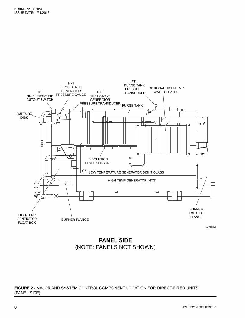
EVAPORATOR / ABSORBERSHELL SECTION
RUPTURE DISKOUTLET FLANGE
LOW-TEMPGENERATOR
(LTG)
BURNERFLANGE
SOLUTION PUMP
SOL2ELECTRICALLY ACTUATEDBALL VALVE
PT3PURGE PUMP PRESSURE
TRANSDUCER
SOL1SOLENOID
VALVE
RT11SOLUTION DILUTION PUMP
TEMP. SENSOR
LRTLOW REFRIGERANT TEMP. CUTOUT SWITCH
RT6FIRST STAGE GENERATOR
TEMP. SENSOR
PT4PURGE TANKPRESSURE
TRANSDUCER
RT12LEAVING REFRIGERANTTEMPERATURE SENSOR
RT10REFRIGERANTTEMP. SENSOR
(G1)SOLUTION TANK
SIGHT GLASS
G4HIGH-TEMPERATURE
GENERATORSIGHT GLASS
BURNER END
LD06083a
FIGURE 3 - MAJOR AND SYSTEM CONTROL COMPONENT LOCATION FOR DIRECT-FIRED UNITS (BURNER END)
JOHNSON CONTROLS10
FORM 155.17-RP3 ISSUE DATE: 1/31/2013
STEAM INLET END
LD06084a
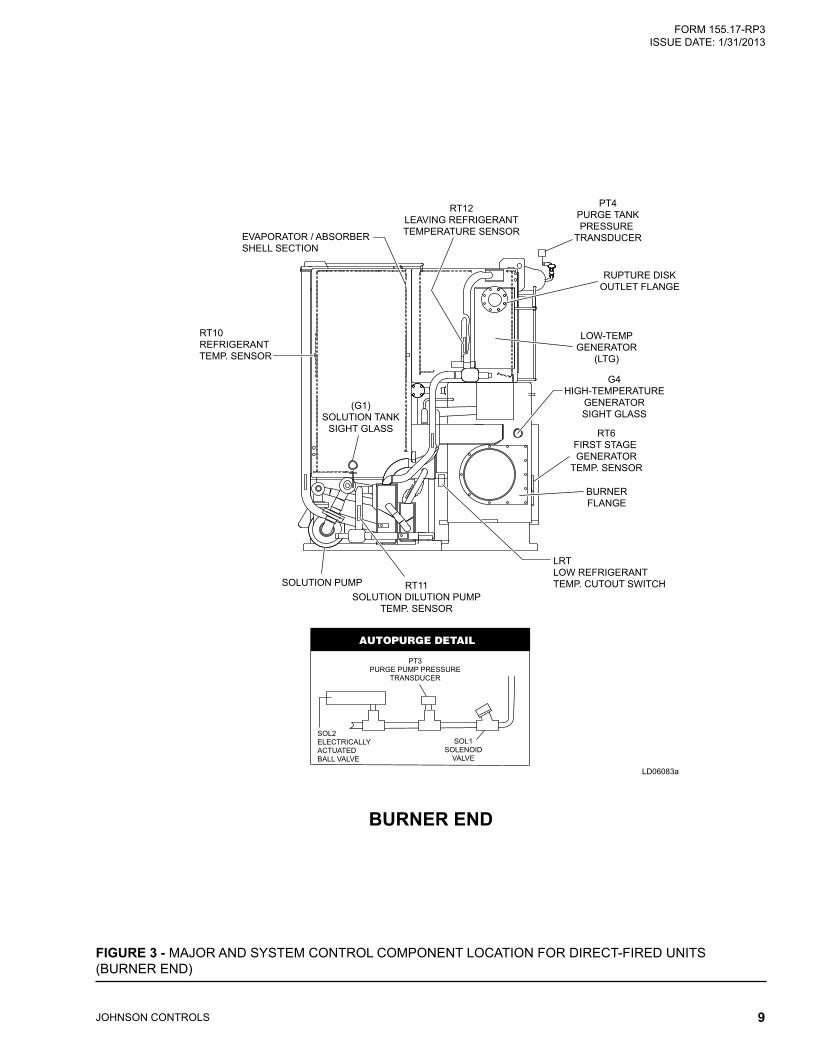
NOTES FOR ALL STEAM-FIRED UNITS:1. Not all system components are shown on any one diagram.2. The following system control is located on the side of the unit Power Panel:
HT1 – First-Stage Generator High Temperature Cutout Control3. The following sensors are located on unit waterbox nozzles and are not shown:
RT1 – Leaving Chilled Water Temperature Sensor RT4 – Leaving Condenser Water Temperature Sensor RT5 – Entering Absorber Water Temp. Sensor RT9 – Entering Chilled Water Temp. Sensor
FIGURE 4 - MAJOR AND SYSTEM CONTROL COMPONENT LOCATION FOR STEAM-FIRED UNITS (STEAM INLET END)
STEAMINLET
LOW TEMPERATUREGENERATOR (LTG)
EVAPORATOR /ABSORBER
SHELLSECTION
REFRIGERANTPUMP
PT4PURGE TANKPRESSURE
TRANSDUCER
LRTLOW REFRIGERANT
TEMP. CUTOUT SWITCH
G6 OIL SEPARATERSIGHT GLASS
MAJOR AND SYSTEM CONTROL COMPONENT LOCATION FOR STEAM-FIRED UNITS

JOHNSON CONTROLS 11
FORM 155.17-RP3 ISSUE DATE: 1/31/2013
PANEL SIDE (NOTE: PANELS NOT SHOWN)
LD06085a
FIGURE 5 - MAJOR AND SYSTEM CONTROL COMPONENT LOCATION FOR STEAM-FIRED UNITS (PANEL SIDE)
RUPTUREDISK
STEAM CONDENSATEDRAIN COOLER
STEAMINLET
HIGH TEMPERATUREGENERATOR (HTG)
PURGE TANK
PT1FIRST STAGEGENERATORPRESSURE
GAUGE
HP1HIGH PRESSURECUTOUT SWITCH
PT1FIRST STAGE GENERATOR
PRESSURE GAUGE
G5 SECOND STAGE GENERATOR SIGHT GLASS
RT6FIRST STAGE GENERATOR
TEMP. SENSOR
G4FIRST STAGEGENERATORSIGHT GLASS
5SOLSTEAM CONDENSATE
OUTLET SOLENOID VALVE
PT4PURGE TANK
PRESSURE TRANSDUCER

JOHNSON CONTROLS12
FORM 155.17-RP3 ISSUE DATE: 1/31/2013
OPPOSITE END
LD06086a
FIGURE 6 - MAJOR AND SYSTEM CONTROL COMPONENT LOCATION FOR STEAM-FIRED UNITS (OPPOSITE END)
RUPTUREDISK
LOW TEMPERATURE
GENERATOR (LTG)
EVAPORATOR /ABSORBER
SHELL SECTION
G4FIRST STAGEGENERATORSIGHT GLASS
RT12LEAVING REFRIGERANT
TEMP. SENSOR
G1SOLUTION
TANK SIGHTGLASS
RT11SOLUTION DILUTIONPUMP TEMP. SENSOR

JOHNSON CONTROLS 13
FORM 155.17-RP3 ISSUE DATE: 1/31/2013
RUPTURE DISK
STEAM INLET
REFRIGERANT PUMP
SOLUTION PUMP
SOLUTION SPRAY PUMP
LRT TEMPSENSOR G2
REFRIGERANTTANK SIGHT GLASS
RT10REFRIGERANT TEMP. SENSOR
G3EVAP. SIGHT GLASS
RT11SOLUTION DILUTIONPUMP TEMP. SENSOR
SOL2ELECTRICALLY ACTUATEDBALL VALVE
PT3PURGE PUMP PRESSURE
TRANSDUCER
SOL1SOLENOID
VALVE
OPPOSITE PANEL SIDE
LD06087a
FIGURE 7 - MAJOR AND SYSTEM CONTROL COMPONENT LOCATION FOR STEAM-FIRED UNITS (OPPOSITE PANEL SIDE)

JOHNSON CONTROLS14
FORM 155.17-RP3 ISSUE DATE: 1/31/2013
TABLE 1 - MAIN CONTROL PANEL
ITEM DESCRIPTION PART NUMBER QUANTITY FIGURE1 Micro Panel Enclosure and Door 371-01288-301 1 1, 2, 34 Relay (1R) 024-23962-000 1 15 Transformer (1T) 025-27911-000 1 16 Fuse, 7 AMP (1FU) 025-29905-000 1 19 Control, I/O Expansion Board 031-01301-001 1 2
10 Control, Power Supply Board 031-01080-000 1 212 Cable, Ribbon - I/O Expansion Board J9 & J10 031-01322-000 2 213 Fastener, Pawl, Adjustable 021-17252-000 1 314 Clamp, Ribbon Wire 025-29103-000 1 115 Strap, Cable 025-11098-000 2 116 Strap, Cable 025-09607-000 1 217 Display, Panel 031-03277-000 1 318 Switch, Rocker 024-23143-000 1 319 Clamp, Ribbon Wire 025-25156-000 11 120 Mount, Cable Strap 025-25155-000 5 322 Label, Identification 035-07878-000 1 323 Label, Caution 035-03908-000 1 324 Label, Caution 035-05548-000 1 325 Label, Notice 035-05973-000 1 326 Label, Caution 035-07425-000 1 327 Strip, Marker 025-29933-000 1 228 Strip, Marker 025-29911-000 1 229 Cable, Ribbon - Relay Board J3 031-01323-000 1 1, 230 Cable, Ribbon - Keypad 031-00950-000 1 1, 2, 331 Cable, Ribbon - Relay Board J1 031-00951-000 1 1, 232 Cable, Ribbon - Display 031-00952-000 1 1, 2, 333 Cable, Ribbon - Digital Input Board J1 031-00953-000 1 134 Cable, Ribbon - Micro Board J2 031-01321-000 1 235 Nameplate, Patent 029-20119-000 1 337 Terminal Block 025-20944-000 17 238 Terminal Block 025-20945-000 14 239 Terminal Block End 025-20946-000 2 240 Spacer, #8-32 x 3-3/4 long 021-17256-000 4 1, 242 Spacer, #6-32 x 3/4 long 021-17259-000 4 343 Nut, Expansion 021-14661-000 30 1, 250 Screw, #6-32 x 3/4 long 021-03739-000 4 351 Spacer, RAF 1127-6-N-O 021-17776-000 4 352 Spacer, Cable 025-18167-000 10 1, 2, 353 Washer, Cup 021-14191-000 16 254 Screw, Tap, Type F Hex Head, #10-32 x 3/8 long 021-17608-000 17 256 Screw, Machine #10-24 x 3/8 long 021-03745-000 6 2, 357 Screw, Tap Type B Pan Head, #10 x 1/2 long 021-13789-000 18 1, 258 Screw, Tap, Type B Pan Head, #8 x 1-1/4 long 021-14667-000 30 260 Screw, Tap Type B Pan Head, #8 x 3/8 long 021-13783-000 16 1, 261 Screw, Tap Cut Type F, #6 x 1/2 long 021-13721-000 6 2
MAIN CONTROL PANEL

JOHNSON CONTROLS 15
FORM 155.17-RP3 ISSUE DATE: 1/31/2013
TABLE 1 - MAIN CONTROL PANEL (CONT’D)
ITEM DESCRIPTION PART NUMBER QUANTITY FIGURE62 Screw, Mach. Head, #8-32 x 1/2 long 021-01722-000 4 163 Screw, Mach. Head, #6-32 x 3/8 long 021-01692-000 4 364 Nut/Washer (KEPS), #10-24 021-18024-000 11 1, 2, 365 Lockwasher, Internal Tooth, #6 021-01132-000 8 366 Lockwasher, #10 021-01137-000 2 367 Lockwasher, #8 021-01133-000 4 168 Washer, Plain , #6 021-11641-000 2 269 Nut/Washer (KEPS) #8-32 021-17664-000 4 172 Wiring Harness, Main 571-01288-201 1 173 Wiring Harness, Card Cage 571-01111-001 1 175 Wiring Harness, Door 571-01288-211 1 377 Screw/Washer (SEMS) 021-17268-000 4 278 Suppressor (Note 1) 031-00808-000 1 280 Insulator, Display 071-01113-000 1 382 Screw, Recessed Pan Head, 1/4-20 x 3/4 long 021-03748-000 1 283 Nut Hex, 1/4-20 021-00451-000 1 284 Lockwasher, Internal Lock Tooth, 1/4 021-01148-000 1 285 Control Micro Board, 2meg (NOTE 2) 031-01065-002 1 2
104 Control Relay Board 031-01199-000 1 2105 Label, Fuse 025-29931-000 1 2107 Fuse Holder 025-13991-000 1 1108 Screw, Serrated Head, #10 x 1/2 long 021-14786-000 4 2151 Eprom, Programmed, 2 meg (NOTE 4) See Chart, Note 4 1 2152 Keypad 024-25570-000 1 3154 Control, Digital Input Board (standard) 031-01621-001 1 2154 Control, Digital Input Board (VDE) 031-01621-002 1 2155 Jumper, Terminal Block 025-13984-000 3 2156 IC, Real Time Clock - U16 031-00955-000 1 —157 Control, Remote Reset (Customer Option) 031-00814-000 note 3 —158 Card File (Customer Option) 031-00827-000 1 — 159 MOV 115 Volts Applications 331-00485-000 NOTE 5 —160 RS-485, U43 Chip 025-40528-000 1 —
NOTES:1. In addition to this suppressor, not shown are six additional suppressors of the same part number, shipped loose for field use to place across
the coil of any relay or contactor connected to the control panel or its 115 VAC power supply, including the application of: Alarm Circuit Relays Pump Starter (contactor) Flow Switch Inputs BAS Inputs
2. Replacement Micro Boards are supplied without Eprom. Remove Eprom from defective board and use in replacement board. See item #151 if Eprom must also be replaced.
3. If it is desired to remotely reset both the leaving water temperature setpoint (gas/oil or steam) and the load limit setpoint (steam units only), 2 each remote reset boards are required. Otherwise, only 1 each is required.
4. Older units (built prior to April 1997) use a 1 MEG Micro Board, P/N 031-01065-000 or -001. This Micro Board is compatible with only a 1 MEG EPROM (Version A.01F.12.133.00), YORK P/N 031-01669-002.
IF MICROPANEL CONTAINS MICROBOARD P/N
USE EPROM P/N
EPROM VERSION MEGS
031-01065-000 or 001 031-01669-002 A.01F.12.133.00 1031-01065-002 031-02069-001 A.01F.13 or Later 2
5. Part no. consists of: 1-(031-00266-000) MOV and 2-(025-11190-000) straight - Push on spade terminals.

JOHNSON CONTROLS16
FORM 155.17-RP3 ISSUE DATE: 1/31/2013
FIG
UR
E 8
- MA
IN C
ON
TRO
L PA
NE
L C
OM
PO
NE
NTS
1
LD06
088a

JOHNSON CONTROLS 17
FORM 155.17-RP3 ISSUE DATE: 1/31/2013
LD06
089
FIG
UR
E 9
- MA
IN C
ON
TRO
L PA
NE
L C
OM
PO
NE
NTS
2

JOHNSON CONTROLS18
FORM 155.17-RP3 ISSUE DATE: 1/31/2013
FIG
UR
E 10
- M
AIN
CO
NTR
OL
PAN
EL
CO
MP
ON
EN
TS 3
LD03
289

JOHNSON CONTROLS 19
FORM 155.17-RP3 ISSUE DATE: 1/31/2013
TABLE 2 - MAIN CONTROL PANEL ELECTRICAL CONNECTIONS
APPLICATION POSITION PINS PLUG PART NO. PIN PART NO.MicroBoard J3 2 025-21136-000 025-19674-000MicroBoard J8 4 025-21138-000 025-19674-000MicroBoard J17 15 025-28385-000 025-28386-000MicroBoard J19 12 025-28384-000 025-28386-000MicroBoard J21 9 025-28383-000 025-28386-000MicroBoard J22 6 025-28382-000 025-28386-000I/O Expansion Board J1 2 025-29130-000 025-28386-000I/O Expansion Board J3 2 025-29130-000 025-28386-000I/O Expansion Board J4 6 025-28382-000 025-28386-000I/O Expansion Board J5 4 025-28959-000 025-28386-000I/O Expansion Board J6 3 025-29185-000 025-28386-000I/O Expansion Board J7 2 025-21136-000 025-19674-000I/O Expansion Board J8 6 025-28382-000 025-28386-000Power Supply Board J1 3 025-21137-000 025-32506-000Power Supply Board J2 4 025-21138-000 025-19674-000Power Supply Board J3 2 025-21136-000 025-32506-000Power Supply Board J4 3 025-21137-000 025-19674-000Power Supply Board J6 2 025-29130-000 025-28386-000Digital Board J2 3 025-21137-000 025-19674-000Relay Board J2 2 025-21136-000 025-19674-000
DANGLING CONNECTER (Connects Door Harness With Main Panel Harness)
Application Position Pins Description Part No.MicroPanel Door 9 Connector 025-21192-000MicroPanel Door 9 Pin 025-22214-000MicroPanel Door 9 Mate 025-21191-000MicroPanel Door 9 Socket 025-22215-000Insulated Spring Spade Terminal for Shielded Cable Drain Wire Connection to Panel 025-19407-000Un-Insulated, Straight Push-On Connection Terminal with Insulation Support Clamp 025-06874-000

JOHNSON CONTROLS20
FORM 155.17-RP3 ISSUE DATE: 1/31/2013
LD03290A
THERMISTOR CONNECTIONS
TABLE 3 - UNIT THERMISTORS CONNECTIONS
APPLICATION ITEM DESCRIPTION PART NO.Shielded Cable, Sensor End 1 Two-Pin Housing (plug) (for Thermistor Connection) 025-28951-000Shielded Cable, Sensor End 3 Rubber Collars to fit over wire insulation 025-28950-000Shielded Cable, Sensor End 4 Contact Female Receptacles (metal female terminals) 025-28952-000Thermistor (Pig-Tail) 5 Two-Pin Housing (cap) for sensor end (supplied with Thermistor) 025-28948-000Thermistor (Pig-Tail) 3 Rubber Collars to fit over wire insulation (supplied with Thermistor) 025-28950-000Thermistor (Pig-Tail) 6 Contact (male) Tabs (metal terminals) (supplied with Thermistor) 025-28949-000
Unit Wiring 10Cable, 2-Conductor Cable with Foil Shield & Drain Wire 20AWG(for Thermistor)
025-28701-002
FIGURE 11 - ELECTRICAL CONNECTIONS (THERMISTOR)
10
LD03292a
DETAIL A
JOHNSON CONTROLS 21
FORM 155.17-RP3 ISSUE DATE: 1/31/2013
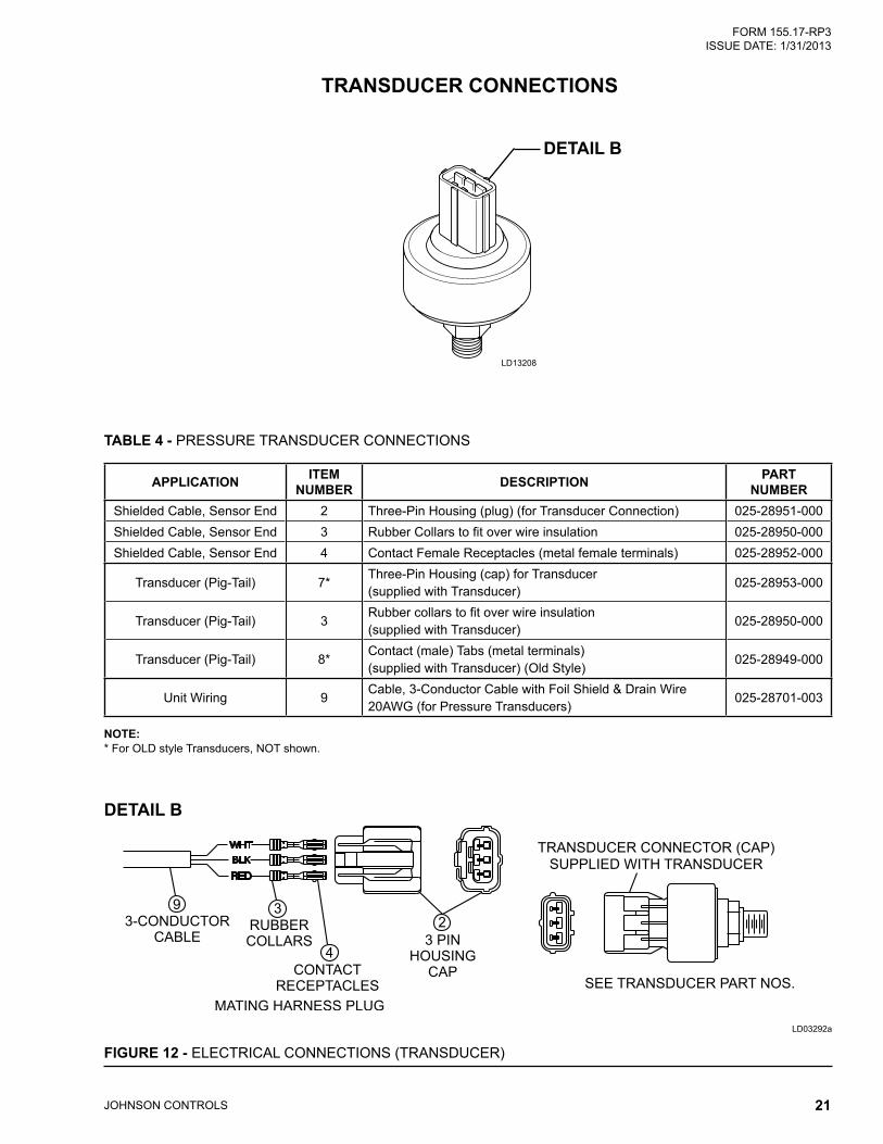
TABLE 4 - PRESSURE TRANSDUCER CONNECTIONS
APPLICATION ITEM NUMBER DESCRIPTION PART
NUMBERShielded Cable, Sensor End 2 Three-Pin Housing (plug) (for Transducer Connection) 025-28951-000Shielded Cable, Sensor End 3 Rubber Collars to fit over wire insulation 025-28950-000Shielded Cable, Sensor End 4 Contact Female Receptacles (metal female terminals) 025-28952-000
Transducer (Pig-Tail) 7*Three-Pin Housing (cap) for Transducer (supplied with Transducer)
025-28953-000
Transducer (Pig-Tail) 3Rubber collars to fit over wire insulation (supplied with Transducer)
025-28950-000
Transducer (Pig-Tail) 8*Contact (male) Tabs (metal terminals) (supplied with Transducer) (Old Style)
025-28949-000
Unit Wiring 9Cable, 3-Conductor Cable with Foil Shield & Drain Wire 20AWG (for Pressure Transducers)
025-28701-003
NOTE:* For OLD style Transducers, NOT shown.
LD03292a
FIGURE 12 - ELECTRICAL CONNECTIONS (TRANSDUCER)
10
DETAIL B
TRANSDUCER CONNECTIONS
LD13208
DETAIL B
JOHNSON CONTROLS22
FORM 155.17-RP3 ISSUE DATE: 1/31/2013
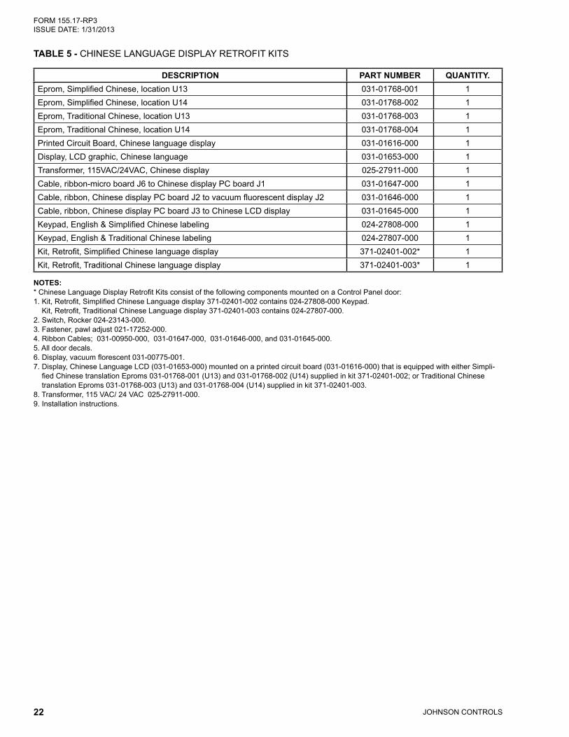
TABLE 5 - CHINESE LANGUAGE DISPLAY RETROFIT KITS
DESCRIPTION PART NUMBER QUANTITY.Eprom, Simplified Chinese, location U13 031-01768-001 1Eprom, Simplified Chinese, location U14 031-01768-002 1Eprom, Traditional Chinese, location U13 031-01768-003 1Eprom, Traditional Chinese, location U14 031-01768-004 1Printed Circuit Board, Chinese language display 031-01616-000 1Display, LCD graphic, Chinese language 031-01653-000 1Transformer, 115VAC/24VAC, Chinese display 025-27911-000 1Cable, ribbon-micro board J6 to Chinese display PC board J1 031-01647-000 1Cable, ribbon, Chinese display PC board J2 to vacuum fluorescent display J2 031-01646-000 1Cable, ribbon, Chinese display PC board J3 to Chinese LCD display 031-01645-000 1Keypad, English & Simplified Chinese labeling 024-27808-000 1Keypad, English & Traditional Chinese labeling 024-27807-000 1Kit, Retrofit, Simplified Chinese language display 371-02401-002* 1Kit, Retrofit, Traditional Chinese language display 371-02401-003* 1
NOTES:* Chinese Language Display Retrofit Kits consist of the following components mounted on a Control Panel door:1. Kit, Retrofit, Simplified Chinese Language display 371-02401-002 contains 024-27808-000 Keypad.
Kit, Retrofit, Traditional Chinese Language display 371-02401-003 contains 024-27807-000.2. Switch, Rocker 024-23143-000.3. Fastener, pawl adjust 021-17252-000.4. Ribbon Cables; 031-00950-000, 031-01647-000, 031-01646-000, and 031-01645-000.5. All door decals.6. Display, vacuum florescent 031-00775-001.7. Display, Chinese Language LCD (031-01653-000) mounted on a printed circuit board (031-01616-000) that is equipped with either Simpli-
fied Chinese translation Eproms 031-01768-001 (U13) and 031-01768-002 (U14) supplied in kit 371-02401-002; or Traditional Chinese translation Eproms 031-01768-003 (U13) and 031-01768-004 (U14) supplied in kit 371-02401-003.
8. Transformer, 115 VAC/ 24 VAC 025-27911-000.9. Installation instructions.

JOHNSON CONTROLS 23
FORM 155.17-RP3 ISSUE DATE: 1/31/2013
TABLE 6 - POWER PANEL COMPONENTS CONTACTORS AND OVERLOADS FOR PURGE PUMP MOTOR
DESCRIPTION VOLT CODE
CONTACTOR / OVERLOAD
MODEL UNITSDIRECT FIRED UNITS STEAM UNITS
ALL MODELS 14SC AND 15S 16SL THRU 19SPurge Pump
Motor Contactor (3M)
ALL Contactor 024-25522-000 024-25522-000 024-25522-000
Purge Pump Motor
Overload (3OL)
17 Overload 024-25576-000 024-25576-000 024-25576-00028 Overload 024-25576-000 024-27278-000 024-25576-00046 Overload 024-26186-000 024-27277-000 024-26186-00050 Overload 024-26186-000 024-27278-000 024-26186-000
TABLE 7 - CONTACTORS AND OVERLOADS FOR LIQUID PUMP ON TWO PUMP UNITS
DESCRIPTION VOLT CODE
CONTACTOR / OVERLOAD
UNIT MODELSDIRECT-FIRED STEAM
12SC AND 13S 13SC AND 14S 14SC AND 15S 15SL AND 16S 14SC AND 15S
Solution Pump Motor Contactor
(1M) and Overload (1OL)
17Contactor 024-25584-000 024-25584-000 024-25584-000 024-25584-000 024-25584-000Overload 024-26187-000 024-26187-000 024-26187-000 024-25581-000 024-26187-000
28Contactor 024-25584-000 024-25584-000 024-25584-000 024-25584-000 024-25584-000Overload 024-26187-000 024-26187-000 024-26187-000 024-25581-000 024-27284-000
46Contactor 024-25584-000 024-25584-000 024-25584-000 024-25526-000 024-25584-000Overload 024-25587-000 024-25587-000 024-25587-000 024-25587-000 024-27268-000
50Contactor 024-25584-000 024-25584-000 024-25584-000 024-25584-000 024-25584-000Overload 024-25587-000 024-25587-000 024-25587-000 024-25587-000 024-27282-000
Refrigerant Pump Motor Contactor
(2M) and Overload (2OL)
17 Contactor 024-25521-000 024-25521-000 024-25521-000 024-25526-000 024-25521-000Overload 024-25578-000 024-25578-000 024-25578-000 024-25587-000 024-25579-000
28 Contactor 024-25521-000 024-25521-000 024-25521-000 024-25526-000 024-25521-000Overload 024-25578-000 024-25578-000 024-25578-000 024-25578-000 024-25579-000
46 Contactor 024-25521-000 024-25521-000 024-25521-000 024-25521-000 024-25521-000Overload 024-25577-000 024-25577-000 024-25577-000 024-25578-000 024-27280-000
50 Contactor 024-25521-000 024-25521-000 024-25521-000 024-25521-000 024-25521-000Overload 024-25576-000 024-25576-000 024-25576-000 024-25579-000 024-27280-000
NOTE: Contactors include suppressors.
SEE FIGURES 13 AND 14
POWER PANEL COMPONENTS

JOHNSON CONTROLS24
FORM 155.17-RP3 ISSUE DATE: 1/31/2013
FIGURE 13 - 2 PUMP UNITSLD06090

JOHNSON CONTROLS 25
FORM 155.17-RP3 ISSUE DATE: 1/31/2013
TABLE 8 - POWER PANEL COMPONENTS CONTACTORS AND OVERLOADS FOR LIQUID PUMPS ON THREE PUMP, DIRECT-FIRED UNITS
DESCRIPTION VOLT CODE
CONTACTOR/ OVERLOAD
UNIT MODELS16SL 17S 18S 19S
Solution Pump Motor Contactor
(1M) and Overload (1OL)
17Contactor 024-25585-000 024-25585-000 024-25585-000 024-25585-000Overload 024-25582-000 024-25581-000 024-25581-000 024-25581-000
28Contactor 024-25585-000 024-25585-000 024-25585-000 024-25585-000Overload 024-27287-000 024-25581-000 024-25581-000 024-25581-000
46Contactor 024-25584-000 024-25584-000 024-25584-000 024-25584-000Overload 024-26187-000 024-25580-000 024-25580-000 024-25580-000
50Contactor 024-25584-000 024-25584-000 024-25584-000 024-25584-000Overload 024-26187-000 024-25580-000 024-25580-000 024-25580-000
Refrigerant Pump Motor Contactor
(2M) and Overload (2OL)
17Contactor 024-25526-000 024-25526-000 024-25526-000 024-25526-000Overload 024-25587-000 024-25587-000 024-25587-000 024-25587-000
28Contactor 024-25526-000 024-25526-000 024-25526-000 024-25526-000Overload 024-25587-000 024-25587-000 024-25587-000 024-25587-000
46Contactor 024-25521-000 024-25521-000 024-25521-000 024-25521-000Overload 024-25578-000 024-25578-000 024-25578-000 024-25578-000
50Contactor 024-25526-000 024-25526-000 024-25526-000 024-25526-000Overload 024-25579-000 024-25579-000 024-25579-000 024-25579-000
Solution Spray Pump Motor
Contactor (4M) and Overload
(4OL)
17Contactor 024-25526-000 024-25526-000 024-25526-000 024-25585-000Overload 024-25587-000 024-25587-000 024-25587-000 024-25581-000
28Contactor 024-25526-000 024-25526-000 024-25526-000 024-25585-000Overload 024-25587-000 024-25587-000 024-25587-000 024-25581-000
46Contactor 024-25521-000 024-25521-000 024-25521-000 024-25584-000Overload 024-25578-000 024-25578-000 024-25578-000 024-25587-000
50Contactor 024-25521-000 024-25521-000 024-25521-000 024-25584-000Overload 024-25579-000 024-25579-000 024-25579-000 024-25580-000
NOTE: Contactors include suppressors.
SEE FIGURE 14 ON FOLLOWING PAGE

JOHNSON CONTROLS26
FORM 155.17-RP3 ISSUE DATE: 1/31/2013
FIGURE 14 - 3 PUMP UNITS
LD03442

JOHNSON CONTROLS 27
FORM 155.17-RP3 ISSUE DATE: 1/31/2013
TABLE 9 - POWER PANEL COMPONENTS CONTACTORS AND OVERLOADS FOR LIQUID PUMPS ON THREE PUMP, STEAM-FIRED UNITS
DESCRIPTION VOLT CODE
CONTACTOR/ OVERLOAD
UNIT MODELS16SL 17S 18S 19S
Solution Pump Motor Contactor
(1M) and Overload (1OL)
17Contactor 024-25585-000 024-25585-000 024-25585-000 024-25585-000Overload 024-25581-000 024-25581-000 024-25581-000 024-25581-000
28Contactor 024-25585-000 024-25585-000 024-25585-000 024-25585-000Overload 024-25581-000 024-25581-000 024-25581-000 024-25581-000
46Contactor 024-25584-000 024-25584-000 024-25584-000 024-25584-000Overload 024-25580-000 024-25580-000 024-25580-000 024-25580-000
50Contactor 024-25584-000 024-25584-000 024-25584-000 024-25584-000Overload 024-25580-000 024-25580-000 024-25580-000 024-25580-000
Refrigerant Pump Motor Contactor
(2M) and Overload (2OL)
17Contactor 024-25526-000 024-25526-000 024-25526-000 024-25526-000Overload 024-25587-000 024-25587-000 024-25587-000 024-25587-000
28Contactor 024-25526-000 024-25526-000 024-25526-000 024-25526-000Overload 024-25587-000 024-25587-000 024-25587-000 024-25587-000
46Contactor 024-25521-000 024-25521-000 024-25521-000 024-25521-000Overload 024-25579-000 024-25579-000 024-25579-000 024-25578-000
50Contactor 024-25521-000 024-25521-000 024-25521-000 024-25521-000Overload 024-25579-000 024-25579-000 024-25579-000 024-25579-000
Solution Spray Pump Motor
Contactor (4M) and Overload
(4OL)
17Contactor 024-25526-000 024-25526-000 024-25526-000 024-25585-000Overload 024-25587-000 024-25587-000 024-25587-000 024-25581-000
28Contactor 024-25526-000 024-25526-000 024-25526-000 024-25585-000Overload 024-25587-000 024-25587-000 024-25587-000 024-25581-000
46Contactor 024-25521-000 024-25521-000 024-25521-000 024-25584-000Overload 024-25579-000 024-25579-000 024-25579-000 024-25587-000
50Contactor 024-25521-000 024-25521-000 024-25521-000 024-25584-000Overload 024-25579-000 024-25579-000 024-25579-000 024-25580-000
NOTE: Contactors include suppressors.
SEE FIGURE 14

JOHNSON CONTROLS28
FORM 155.17-RP3 ISSUE DATE: 1/31/2013
TABLE 10 - POWER PANEL COMPONENTS NON-FUSED DISCONNECT SWITCHES
DESCRIPTION VOLT CODE
DIRECT FIRED UNIT MODELS12SC AND 13S 13SC AND 14S 14SC AND 15S 15SL 16S
Non-Fused Disconnect
SwitchALL 024-25575-000 024-25575-000 024-25575-000 024-25575-000 024-25575-000
DESCRIPTION VOLT CODE
DIRECT FIRED UNIT MODELS16SL 17S 18S 19S
Non-Fused Disconnect
Switch
17 024-25565-000 024-25565-000 024-25565-000 024-25565-00028 024-25565-000 024-25565-000 024-25565-000 024-25565-00046 024-25575-000 024-25575-000 024-25575-000 024-25575-00050 024-25575-000 024-25575-000 024-25575-000 024-25575-000
DESCRIPTION VOLT CODE
DIRECT FIRED UNIT MODELS16SL 17S 18S 19S
Non-Fused Disconnect
SwitchALL 024-25575-000 024-25575-000 024-25575-000 024-25575-000
TABLE 11 - POWER PANEL COMPONENTS CONTROL COMPONENTS
ITEM DESCRIPTION VOLT. CODE QUANTITY PART NUMBER
1 Control Transformer
17 1 025-28664-00128 1 025-28664-00246 1 025-28664-00250 1 025-28664-003
2 Primary Fuse (1 FU, 2 FU)
17 2 025-27972-00028 2 025-27971-00046 2 025-27922-00050 2 025-27922-000
3Primary Fuse (3 FU) ALL 1 025-27971-000Fuseholder All 3 025-17407-000
4Relay Control (2R) ALL 1 024-23962-000Suppressor (NOT SHOWN) (used with item 4) ALL 1 031-00808-000
5 First Stage Generator High Temp. Control (HT1) ALL 1 025-29995-000
6
Low Solution Level Control (LS) (direct-fired units only)
ALL
225-29922-000 Kit Contains:1) Level Controller 1 025-29922-0002) Electrode (Probe) 024-25572-0003) Wiring Kit 575-06503-451
7 Housing Plug, Universal (9 pin) (J2) all 1 025-21192-0008 Housing Plug, Universal (12 pin) (J1) all 1 025-21196-000
9Socket, Universal Female all - 025-19673-000Mating Pins for Item 9 (Pin or male) All - 025-20533-000
REFER TO FIGURE ON FOLLOWING PAGE FOR COMPONENT LOCATIONS

JOHNSON CONTROLS 29
FORM 155.17-RP3 ISSUE DATE: 1/31/2013
LD06091
REFER TO TABLE ON PREVIOUS PAGE FOR COMPONENT DESCRIPTION
TABLE 12 - SYSTEM CONTROL COMPONENTS LOCATED ON UNIT
DESCRIPTION VOLT. CODE QUANTITY
PART NUMBERDIRECT-FIRED STEAM
Temperature Sensor (50,000 Ohms) RT6 & RT11 (First Stage Generator & Solution/Dilution)
ALL 2 025-29924-000 025-29924-000
Temperature Sensor (3,000 Ohms) (Low temperature areas of unit) (includes RT12)
ALL 6 025-29964-000 025-29964-000
Temperature Sensor (3,000 Ohms) (Hi-temp aux. Heating, Direct-Fired Units only)
ALL 8 025-29964-000 —
Varistor, Metal Oxide (used with Honeywell Steam Valve Actuator)
ALL 2 — 031-01349-000
Suppressor (used with Steam Solenoid Valve, 5SOL) ALL 1 — 031-00808-000Current Switch (used only on 16SL and 17S units) ALL 8 — 025-30974-000Low Refrigerant Temp. Control (LRT) ALL 1 225-30494-000 225-30494-000Pressure Transducer (PT1) ALL 1 025-29907-001 025-29907-001Pressure Transducer (PT3, PT4) for Auto-Purge ALL 2 025-29907-002 025-29907-002Isolator (vilter steady mount) (for use with PT1) ALL 1 026-30229-000 026-30229-000First stage generator High Pressure Control (HP1) (calibrated to 710 mm Hg) UEDA
ALL 1 224-25525-058 224-25525-058
High Pressure Cutout (HPI) UE ALL - 024R00132-000Cable, 2-conductor gray cable with foil shield and drain wire 20 AWG - for thermistors
ALL — 025-28701-002 025-28701-002
Cable, 3-conductor gray cable with foil shield and drain wire 20 AWG - for pressure transducers
ALL — 025-28701-003 025-28701-003
MOV 155 Volts Applications (See Note 2) ALL — 331-00485-000 331-00485-000
NOTES: 1. See major component location drawings in this document for system control locations on unit. 2. Part no. consists of: 1-(031-0266-000) MOV and 2-(025-11190) straight - Push on spade terminals.
SYSTEM CONTROL COMPONENTS
JOHNSON CONTROLS30
FORM 155.17-RP3 ISSUE DATE: 1/31/2013
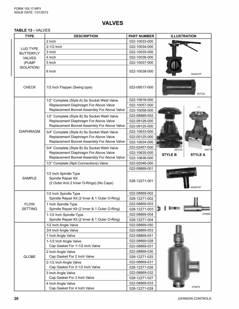
TABLE 13 - VALVESTYPE DESCRIPTION PART NUMBER ILLUSTRATION
LUG TYPE BUTTERFLY
VALVES (PUMP
ISOLATION)
2 Inch 022-10033-000
00402VIP
2-1/2 Inch 022-10034-0003 Inch 022-10035-0004 Inch 022-10036-0005 Inch 022-10037-000
6 Inch 022-10038-000
CHECK 1/2 Inch Flapper (Swing type) 022-09517-000
28733A
DIAPHRAGM
1/2” Complete (Style A) Ss Socket Weld Valve Replacement Diaphragm For Above Valve Replacement Bonnet Assembly For Above Valve
022-10618-000
STYLE A29471A28731A
STYLE B
022-10057-000022-10058-000
1/2” Complete (Style B) Ss Socket Weld Valve Replacement Diaphragm For Above Valve Replacement Bonnet Assembly For Above Valve
022-08869-052022-09126-000022-09125-000
3/4” Complete (Style A) Ss Socket Weld Valve Replacement Diaphragm For Above Valve Replacement Bonnet Assembly For Above Valve
022-10633-000022-05125-000022-10634-000
3/4” Complete (Style B) Ss Socket Weld Valve Replacement Diaphragm For Above Valve Replacement Bonnet Assembly For Above Valve
022-02457-000022-10635-000022-10636-000
1/2” Complete (Npti Connections) Valve 022-02046-000
SAMPLE1/2 Inch Spindle Type Spindle Repair Kit (2 Outer And 2 Inner O-Rings) (No Caps)
022-08869-001
00405VIP
028-12271-001
FLOW SETTING
1/2 Inch Spindle Type Spindle Repair Kit (2 Inner & 1 Outer O-Ring)
022-08869-002
27089A
028-12271-0021 Inch Spindle Type Spindle Repair Kit (2 Inner & 1 Outer O-Ring)
022-08869-003028-12271-003
1-1/2 Inch Spindle Type Spindle Repair Kit (2 Inner & 1 Outer O-Ring)
022-08869-004028-12271-004
GLOBE
1/2 Inch Angle Valve 022-08869-050
27087A
3/4 Inch Angle Valve 022-08869-0531 Inch Angle Valve 022-08869-0511-1/2 Inch Angle Valve Cap Gasket For 1-1/2 Inch Valve
022-08869-028022-08869-031
2 Inch Angle Valve Cap Gasket For 2 Inch Valve
022-08869-030028-12271-025
2-1/2 Inch Angle Valve Cap Gasket For 2-1/2 Inch Valve
022-08869-031028-12271-026
3 Inch Angle Valve Cap Gasket For 3 Inch Valve
022-08869-032028-12271-027
4 Inch Angle Valve Cap Gasket For 4 Inch Valve
022-08869-033028-12271-028
VALVES

JOHNSON CONTROLS 31
FORM 155.17-RP3 ISSUE DATE: 1/31/2013
TABLE 13 - VALVES (CONT’D)TYPE DESCRIPTION PART NUMBER ILLUSTRATION
NEEDLE
3/4 Inch NPTI 022-08891-000
27085A
1 Inch NPTI 022-08892-000
RELIEF HIGH-TEMP
(AUX. HEATER)
3/4 Inch NPTI x 1 (RATED 150 psi) 022-08879-000
28730A
3/4” x 1-1/4” (RATED 300 PSI) 022-10041-000
SOLENOID
1/2 Inch NPTI Purge Tank (1SOL) Valve 022-09563-000
28732A
3/4 Inch Steam condensate drain (5SOL) Valve 025-29538-0021” Steam Condensate Drain Valve (5SOL) 025-29538-003
1-1/4” Steam Condensate Drain Valve (5SOL) 025-29538-004
- Solenoid Valve DIN Plug w/ Suppressor 025-37876-000- Solenoid Valve DIN Plug w/o Suppressor 025-34047-000
ELECTRICALLY ACTUATED
PURGE BALL VALVE
(2 SOL)
1/2” Siemens Actuator W/ Swagelok Ball Valve 022-10042-000
00401VIPBALL VALVE
ACTUATOR
1/2” Swagelok Ball Valve Only 022-10059-000Seal Kit For Above Ball Valve 022-10061-000
Replacement Actuator Only For Above Ball Valve
022-10060-000
NEW STYLE GLOBE VALVES
1/2” With Cap 022R00181-000
00401a
00401b
1” With Cap 022R00180-0001-1/2” With Cap 022-10097-000 Spare Parts Kit1 022-10602-000 Complete Repair Kit2 022-10603-000 Cap Seal Only 022-10620-0002” With Cap 022-10098-000 Spare Parts Kit1 022-10604-000 Complete Repair Kit2 022-10605-000 Cap Seal Only 022-10621-0002-1/2” With Cap 022-10099-000 Spare Parts Kit1 022-10606-000 Complete Repair Kit2 022-10607-000 Cap Seal Only 022-10622-000
1 Used when valve is leaking externally. Contains: gasket for valve cap (1), and O-ring (2) for valve bonnet2 Used when valve is leaking internally. Contains: cone (5), set screw (3), steel balls (4), O-ring (2), packing gland assembly (not shown) and
gasket for valve cap (1).

JOHNSON CONTROLS32
FORM 155.17-RP3 ISSUE DATE: 1/31/2013
TABLE 14 - FLOAT VALVES
UNIT SIZE HIGH TEMP. GENERATOR FLOAT REFRIGERANT FLOATDIRECT-FIRED UNITS
12SC THRU 15S 075-12170-000 075-12036-00015SL THRU 19S 075-04398-000 075-16391-000
STEAM-FIRED UNITS12SC THRU 15S 075-24332-000 075-12036-00015SL THRU 19S 075-16836-000 075-16391-000
NOTES: All float valves are an assembly of: flapper valve, arm, stopper (when applicable), and float ball.
STEAM CONTROL VALVES AND ACTUATORS
TABLE 15 - STEAM CONTROL VALVES AND ACTUATORS
TYPE DESCRIPTION SIZE RATING COMPLETE VALVE PART NUMBER
REPLACEMENT ACTUATOR P/N ILLUSTRATION
GLOBE 2-WAY
Cast Iron Body - 50Hz
2”125#
022-10008-000 022-10070-000
00404VIP
Cast Iron Body - 60Hz 022-10000-000 022-10069-000Steel Body - 50Hz
150#022-10012-000 022-10070-000
Steel Body - 60Hz 022-10004-000 022-10069-000Cast Iron Body - 50Hz
2-1/2”125#
022-10009-000 022-10088-000Cast Iron Body - 60Hz 022-10001-000 022-10086-000Steel Body - 50Hz
150#022-10013-000 022-10088-000
Steel Body - 60Hz 022-10005-000 022-10086-000Cast Iron Body - 50Hz
3”125#
022-10010-000 022-10089-000Cast Iron Body - 60Hz 022-10002-000 022-10087-000Steel Body - 50Hz
150#022-10014-000 022-10089-000
Steel Body - 60Hz 022-10006-000 022-10087-000Cast Iron Body - 50Hz
4”125#
022-10011-000 022-10089-000Cast Iron Body - 60Hz 022-10003-000 022-10087-000Steel Body - 50Hz
150#022-10015-000 022-10089-000
Steel Body - 60Hz 022-10007-000 022-10087-000
NOTES:MOV (Metal Oxide Varistor) for Actuator: 031-01349-000.Harness connector for Globe 2-way Valves: 025-09020-000.
FLOAT VALVES

JOHNSON CONTROLS 33
FORM 155.17-RP3 ISSUE DATE: 1/31/2013
TABLE 16 - PUMPS, COMPLETE ASSEMBLIES
UNIT MODEL VOLTAGE REFRIGERANT PUMP SOLUTION
PUMPSOLUTION
SPRAY PUMPNEW STYLE PUMPS
12SC, 13S 1208/230/460-3-60 026-33600-001 026-33601-001 N/A
380 / 3 / 50 026-33821-001 026-33822-001 N/A
13SC, 14S 1208/230/460-3-60 026-33600-001 026-33601-001 N/A
380 / 3 / 50 026-33821-001 026-33822-001 N/A
14SC, 15S 1208/230/460-3-60 026-33600-001 026-33601-001 N/A
380 / 3 / 50 026-33821-001 026-33822-001 N/A
15SL1208/230/460-3-60 026-33600-003 026-33601-002 N/A
380-3-50 026-33821-003 026-33822-002 N/A
16S1208/230/460-3-60 026-33600-003 026-33601-002 N/A
380-3-50 026-33821-003 026-33822-002 N/A
16SL208/230/460-3-60 026-33600-004 026-33874-001 026-33874-004
380-3-50 026-33821-004 026-33875-001 026-33875-004
17S208/230/460-3-60 026-33600-004 026-33874-001 026-33874-004
380-3-50 026-33821-004 026-33875-001 026-33875-004
18S208/230/460-3-60 026-33600-004 026-33874-002 026-33874-005
380-3-50 026-33821-004 026-33875-002 026-33875-005
19S208/230/460-3-60 026-33600-004 026-33874-002 026-33874-006
380-3-50 026-33821-004 026-33875-003 026-33875-006
NOTE:1. These units have double ended pumps (Solution and Strong Solution pumps operate off of a common motor).
PUMPS

JOHNSON CONTROLS34
FORM 155.17-RP3 ISSUE DATE: 1/31/2013
TABLE 17 - PUMP REPAIR KIT CONTENTS
PUMP REPAIR KIT
MOTOR BEARING REPAIR
NEW MOTOR WITH PUMP REPAIR KIT
CASING GASKETS
ITEM PART ITEM PART ITEM PART ITEM PART9 Casing Wear Ring 9 Casing Wear Ring 9 Casing Wear Ring 65 Casing Gasket
10 Motor Side Wearing 10 Motor Side Wearing 10 Motor Side Wearingring ring ring
15A Impeller 15A Impeller 15A ImpellerLocking Screw Locking Screw Locking Screw
16 Impeller 16 Impeller 16 ImpellerLocking Washer Locking Washer Locking Washer
17 Feather Key, 17 Feather Key, 17 Feather Key,Impeller Impeller Impeller
65 Casing Gasket 65 Casing Gasket 65 Casing Gasket210A Bearing 201 Multi Voltage Motor210 Bearing (Front End)
NOTE:Casing Gasket is O-ring type elastomer.
(SEE ILLUSTRATIONS ON FOLLOWING PAGES FOR COMPONENT LOCATION)

JOHNSON CONTROLS 35
FORM 155.17-RP3 ISSUE DATE: 1/31/2013
FIGURE 15 - SINGLE-ENDED PUMP
LD01656
210
210A
10 9
16
15A
1765
FIGURE 16 - DOUBLE-ENDED PUMP
LD01657
9
17
10
15A
16
210 65
16
15A
210A
10 17
9

JOHNSON CONTROLS36
FORM 155.17-RP3 ISSUE DATE: 1/31/2013
TABLE 18 - PUMP REPAIR KITS NEW STYLE PUMPS
YORK PART NUMBER
(MOTOR-PUMP) MODEL NUMBER
PUMP REPAIR KIT
MOTOR BEAR-ING REPAIR KIT
NEW MOTOR WITH PUMP
REPAIR
CASING GASKET
60 HZ PUMPS026-33600-001 P8 - 106 026-33828-000 026-33826-000 024-26938-000 028-12913-000026-33600-003 66M - 709 026-32389-000 026-32391-000 024-26934-000 028-12700-000026-33600-004 66M - 709 026-32389-000 026-32391-000 024-26934-000 028-12700-000026-33601-001 66R - 709/609 026-33829-0001 026-33827-0002 024-26939-000 028-12914-0003
026-33601-002 66V - 709/609 026-33829-0001 026-33827-0002 024-27206-000 028-12914-0003
026-33874-001 215ZB - 8011 026-32390-000 026-32392-000 024-26937-000 028-12599-000026-33874-002 215ZB - 8011 026-32390-000 026-32392-000 024-26937-000 028-12599-000026-33874-003 215ZB - 8011 026-32390-000 026-32392-000 024-26937-000 028-12599-000026-33874-004 66M - 709 026-32389-000 026-32391-000 024-26934-000 028-12700-000026-33874-005 66M - 709 026-32389-000 026-32391-000 024-26934-000 028-12700-000026-33874-006 215R - 8011 026-32390-000 026-32392-000 024-26936-000 028-12599-000
50 HZ PUMPS026-33821-001 P8 - 106 026-33828-000 026-33826-000 026-33845-000 028-12913-000026-33821-002 P8 - 106 026-33828-000 026-33826-000 026-33845-000 028-12913-000026-33821-003 66R - 709 026-32389-000 026-32391-000 026-34458-000 028-12700-000026-33821-004 66R - 709 026-32389-000 026-32391-000 026-34458-000 028-12700-000026-33822-001 66R - 709/609 026-33829-0001 026-33827-0002 026-33846-000 028-12914-0003
026-33822-002 66V - 709/609 026-33829-0001 026-33827-0002 026-33847-000 028-12914-0003
026-33875-001 215ZB - 8011 026-32390-000 026-32392-000 026-34459-000 028-12599-000026-33875-002 215ZB - 8011 026-32390-000 026-32392-000 026-34459-000 028-12599-000026-33875-003 215ZB - 8011 026-32390-000 026-32392-000 026-34459-000 028-12599-000026-33875-004 66R - 709 026-32389-000 026-32391-000 026-34458-000 028-12700-000026-33875-005 66R - 709 026-32389-000 026-32391-000 026-34458-000 028-12700-000026-33875-006 215R - 8011 026-32340-000 026-32392-000 026-34460-000 028-12599-000
NOTES FOR DOUBLE ENDED PUMPS:1. Quantity of two for all parts in this kit.2. Quantity of two for all parts except for motor bearing in which one set will be included.3. Kit includes two O-ring type gaskets.4. New Style pump inlet and outlet sizes are as follows:5. Pumps require one motor bearing kit and one pump repair kit per pump every 50,000 operating hours.
MODEL INLET (IN.) OUTLET (IN.)106 3 2709 4 3609 4 38011 6 4

JOHNSON CONTROLS 37
FORM 155.17-RP3 ISSUE DATE: 1/31/2013
FIGURE 17 - PUMP, SINGLE-ENDED EXPLODED VIEW
LD06092

JOHNSON CONTROLS38
FORM 155.17-RP3 ISSUE DATE: 1/31/2013
FIGURE 18 - PUMP, DOUBLE-ENDED EXPLODED VIEW 1
LD06093

JOHNSON CONTROLS 39
FORM 155.17-RP3 ISSUE DATE: 1/31/2013
FIGURE 19 - PUMP, DOUBLE-ENDED EXPLODED VIEW 2
LD06094

JOHNSON CONTROLS40
FORM 155.17-RP3 ISSUE DATE: 1/31/2013
TABLE 19 - PURGE VACUUM PUMPS AND PARTS
UNIT MODEL VOLTAGE APPLICATION YORK P/NCOMPLETE YORK MODEL 1400 VACUUM PUMP (0.9 CFM)
S-Models208/230/460-3-60 Standard 026-33637-000
380-3-50 Standard 026-33832-000COMPLETE YORK MODEL 1402 VACUUM PUMP (5.6 CFM)
G-Models
208/230/460-3-60 Standard 026-32305-000575-3-50 Standard 026R00250-000380-3-50 Standard 026-32377-000
208/230/460-3-60 TEFC 026-32842-000
DESCRIPTION QUANTITY PART NUMBERSeal Kit Qty. 1 1-98-4029
Pump Oil 1 gallon 1401DGaskets 1 each 41-0234 & 41-0403
Aluminum Washer Qty. 1 41-0491Steel Case Oil Seal Qty. 1 41-0578
O-ring Tension Washer Qty. 2 41-1266Rubber Washer Qty. 2 41-1267
Seal Cover Gasket Qty. 1 41-2291
YORK Vacuum Pump Gasket and Seal Kit (for YORK Vacuum Pump Model 1402 only)YORK part number 026-32388-000 (order Major Repair Manual before doing any repairs)

JOHNSON CONTROLS 41
FORM 155.17-RP3 ISSUE DATE: 1/31/2013
TABLE 20 - PURGE VACUUM PUMPS AND PARTS MISCELLANEOUS YORK VACUUM PUMP PARTS
DESCRIPTION YORK P/N WELCH P/N COMMENTS
YORK PUMP MODEL NO. 1400
V-belt 028-14422-000 1400A For use with p/n 026-33637-000V-belt 028-14423-000 1399A For use with p/n 026-33832-000Motor Pulley 41-0551 For use with p/n 026-33637-000Motor Pulley 41-2377 For use with p/n 026-33832-000Pump Pulley 41-2191Belt-Guard Replacement kit 1471HBase 41-2115Motor 61-8504A For use with p/n 026-33637-000Motor 61-8717 For use with p/n 026-33832-000Pump Oil 011-00524-004 1407K-15 1 gallon of DUOSEAL OilOwners Manual 67-0696 Models 1400 and 1402Discharge Port Adaptor Fitting 61-8503A 3/4”-20 male machine thds. X 1/2”- NPTEDischarge Pipe Dust Cap 41-1345 3/4”-20 machine thds.
YORK PUMP MODEL NO. 1402
V-belt 028-14424-000 1405AFor use with p/n’s 026-32305-000, 026R00249-000 & 026-32842-000
V-belt 028-14425-000 41-0713 For use with p/n 026-32377-000Motor Pulley 41-0668 For use with p/n’s 026-32305-000 and 026R00249-000Pump Pulley 41-2074 For use with p/n’s 026-32305-000 and 026R00249-000Belt-Guard Replacement Kit 1471G-01 For use with p/n’s 026-32305-000 and 026R00249-000Base 61-8717 For use with p/n’s 026-32305-000 and 026R00249-000Motor 61-8715 For use with p/n 026-33637-000Motor 41-1904 For use with p/n 026-32305-000Pump Oil 011-00524-004 1407K-15 1 gallon of DUOSEAL OilOwners Manual 67-0696 Models 1400 and 1402Discharge Port Adaptor Fitting 61-8492A 1”-20 male machine thds. X 3/4” NPTE X 2-1/4” longDischarge Pipe Dust Cap 41-0612 1”-20 machine thds.

JOHNSON CONTROLS42
FORM 155.17-RP3 ISSUE DATE: 1/31/2013
TABLE 21 - ABSORPTION CHILLER TUBES
CHILLER MODEL / TUBE
OPTION
LENGTH (IN.)
NOM O.D. (IN.)
WALL NOM. THK. (IN.)
ABSORBER TUBES EVAPORATOR TUBES
QTY. TYPE PART NO. QTY. TYPE PART NO.
TUBES FOR UNITS WITH 3/4 INCH THICK TUBESHEETS12SC & 13S
Standard126-1/8 5/8 0.025 405 Bare 007-08446-000 486 40 fpi3 007-08445-000
12SC & 13S Option A
126-1/8 5/8 0.025 405 19 fpi 007-08447-000 — — —
13SC & 14S 126-1/8 5/8 0.025 405 40 fpi 007-08445-000 486 40 fpi3 007-08445-00014SC & 15S 157-5/8 5/8 0.025 405 40 fpi 007-07899-000 486 40 fpi4 007-07899-000
15SL 157-5/8 3/4 0.028 525 Bare2 007-08449-000 366 19 fpi 007-08448-00016S 157-5/8 3/4 0.028 525 Bare2 007-08449-000 408 19 fpi 007-08448-00016SL 197 3/4 0.028 525 Bare2 007-08474-000 366 19 fpi 007-08472-00017S 197 3/4 0.028 525 Bare2 007-08474-000 408 19 fpi 007-08472-00018S 236-3/8 3/4 0.028 525 Bare2 007-08428-000 408 19 fpi 007-08473-00019S 275-3/4 3/4 0.028 525 Bare2 007-08479-000 408 19 fpi 007-08478-000
TUBES FOR UNITS WITH 1 INCH THICK TUBESHEETS12SC & 13S
Standard126-5/8 5/8 0.025 405 Bare 007-08877-000 486 40 fpi3 007-08866-000
12SC & 13S Option A
126-5/8 5/8 0.025 405 19 fpi 007-08863-000 — — —
13SC & 14S 126-5/8 5/8 0.025 405 40 fpi 007-08866-000 486 40 fpi3 007-08866-00014SC & 15S 158-1/8 5/8 0.025 405 40 fpi 007-08865-000 486 40 fpi4 007-08865-000
15SL 158-1/8 3/4 0.028 525 Bare2 007-08880-000 366 19 fpi 007-08868-00016S 158-1/8 3/4 0.028 525 Bare2 007-08880-000 408 19 fpi 007-08868-00016SL 197-1/2 3/4 0.028 525 Bare2 007-08881-000 366 19 fpi 007-08869-00017S 197-1/2 3/4 0.028 525 Bare2 007-08881-000 408 19 fpi 007-08869-00018S 236-7/8 3/4 0.028 525 Bare2 007-08882-000 408 19 fpi 007-08870-00019S 276-1/4 3/4 0.028 525 Bare2 007-08883-000 408 19 fpi 007-08871-000
NOTES:1. All tube material is C-122 copper except as noted.2. On 15SL thru 19S units, the column of absorber tubes adjacent to the evaporator are Bare, 90/10 CuNi, quantity 25. Units with 3/4” thick tube sheets: a. 15SL thru 16S units; 90/10 CuNi tube p/n 007-08823-000. b. 16SL thru 17S units; 90/10 CuNi tube p/n 007-08808-000. c. 18S units; 90/10 CuNi tube p/n 007-08824-000. d. 19S units; 90/10 CuNi tube p/n 007-08825-000. Units with 1” thick tube sheets: a. 15SL thru 16S units; 90/10 CuNi tube p/n 007-08887-000. b. 16SL thru 17S units; 90/10 CuNi tube p/n 007-08888-000. c. 18S units; 90/10 CuNi tube p/n 007-08889-000. d. 19S units; 90/10 CuNi tube p/n 007-08890-000.3. 12SC through 14S units; top 2 rows of evaporator tubes are Bare copper. a. Units with 3/4” thick tube sheets, p/n 007-08446-00, qty 16. b. Units with 1” thick tube sheets, p/n 007-08877-000, qty 16.4. 14SC and 15S units; top 2 rows of evaporator tubes are Bare copper. a. Units with 3/4” thick tube sheets, p/n 007-08426-000, qty 16. b. Units with 1” thick tube sheets, p/n 007-08878-000, qty 16.
TUBES
JOHNSON CONTROLS 43
FORM 155.17-RP3 ISSUE DATE: 1/31/2013
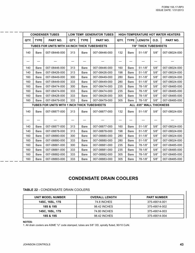
CONDENSER TUBES LOW TEMP. GENERATOR TUBES HIGH-TEMPERATURE HOT WATER HEATERS
QTY. TYPE PART NO. QTY. TYPE PART NO. QTY. TYPE LENGTH O.D. PART NO.
TUBES FOR UNITS WITH 3/4 INCH THICK TUBESHEETS 7/8” THICK TUBESHEETS
140 Bare 007-08446-000 313 Bare 007-08446-000 132 Bare 51-1/8” 5/8” 007-08024-000
— — — — — — — — — — —
140 Bare 007-08446-000 313 Bare 007-08446-000 160 Bare 51-1/8” 5/8” 007-08024-000140 Bare 007-08426-000 313 Bare 007-08426-000 198 Bare 51-1/8” 5/8” 007-08024-000160 Bare 007-08449-000 300 Bare 007-08449-000 280 Bare 51-1/8” 5/8” 007-08024-000160 Bare 007-08449-000 333 Bare 007-08449-000 280 Bare 51-1/8” 5/8” 007-08024-000160 Bare 007-08474-000 300 Bare 007-08474-000 235 Bare 78-1/8” 5/8” 007-08485-000160 Bare 007-08474-000 333 Bare 007-08474-000 235 Bare 78-1/8” 5/8” 007-08485-000160 Bare 007-08428-000 333 Bare 007-08428-000 305 Bare 78-1/8” 5/8” 007-08485-000160 Bare 007-08479-000 333 Bare 007-08479-000 305 Bare 78-1/8” 5/8” 007-08485-000
TUBES FOR UNITS WITH 1 INCH THICK TUBESHEETS ALL .035” WALL THICKNESS
140 Bare 007-08877-000 313 Bare 007-08877-000 132 Bare 51-1/8” 5/8” 007-08024-000
— — — — — — — — — — —
140 Bare 007-08877-000 313 Bare 007-08877-000 160 Bare 51-1/8” 5/8” 007-08024-000140 Bare 007-08878-000 313 Bare 007-08878-000 198 Bare 51-1/8” 5/8” 007-08024-000160 Bare 007-08880-000 300 Bare 007-08880-000 280 Bare 51-1/8” 5/8” 007-08024-000160 Bare 007-08880-000 333 Bare 007-08880-000 280 Bare 51-1/8” 5/8” 007-08024-000160 Bare 007-08881-000 300 Bare 007-08881-000 235 Bare 78-1/8” 5/8” 007-08485-000160 Bare 007-08881-000 333 Bare 007-08881-000 235 Bare 78-1/8” 5/8” 007-08485-000160 Bare 007-08882-000 333 Bare 007-08882-000 305 Bare 78-1/8” 5/8” 007-08485-000160 Bare 007-08883-000 333 Bare 007-08883-000 305 Bare 78-1/8” 5/8” 007-08485-000
TABLE 22 - CONDENSATE DRAIN COOLERS
UNIT MODEL NUMBER OVERALL LENGTH PART NUMBER14SC, 16SL, 17S 74.8 INCHES 375-49014-001
18S & 19S 98.42 INCHES 375-49014-00214SC, 16SL, 17S 74.80 INCHES 375-49014-003
18S & 19S 98.42 INCHES 375-49014-004
NOTES: 1. All drain coolers are ASME “U” code stamped, tubes are 5/8” OD, spirally fluted, 90/10 CuNi.
CONDENSATE DRAIN COOLERS

JOHNSON CONTROLS44
FORM 155.17-RP3 ISSUE DATE: 1/31/2013
TABLE 23 - CHEMICALS AND COMPOUNDS
ITEM DESCRIPTION PART NUMBERADVAguard 750A SOLUTION, 1/2 gallon bottle 011-00931-000ADVAguard 750A SOLUTION, 1 gallon bottle 011-00932-000ADVAguard 750B POWDER, 50 gram container2 011-00933-000ADVAguard 750B POWDER, 100 gram container2 011-00934-000ADVAguard 750B POWDER, 500 gram container2 011-00935-000REFRIGERANT, de-ionized water, 55 gallon drum 011-00548-000LITHIUM BROMIDE SOLUTION, ADVAGuard 750 Inhibited, 30 gallon drum 011-00903-000LITHIUM BROMIDE SOLUTION, Molybdate Inhibited, in 30 gallon drum 011-00556-000LITHIUM BROMIDE SOLUTION, Un-inhibited, 30 gallon drum1 011-00940-000LITHIUM MOLYBDATE INHIBITOR, powder, 1lb. bottle 011-00557-000LITHIUM MOLYBDATE INHIBITOR, Liquid, 1 pint bottle (equals 0.4 lb of Molybdate powder) 011-00905-000LITHIUM NITRATE INHIBITOR, powder, 1 lb. bottle 011-00524-002LITHIUM HYDROXIDE MONOHYDRATE, powder, 5 lbs. 044-02985-000ALCOHOL, (2-Ethyl-1-Hexanol), 5 gallon pail 011-00524-003ADHESIVE, GASKET, 5 oz. tube (for Water Box Gaskets) 013-00995-000CLEANER, Loctite 7070 013-02899-000PRIMER (Loctite Primer “N” 7649), 1.76 oz. bottle 013-01753-000SEALER, Loctite grade AVV 086 (for studs in tubesheets) 013-01671-000SEALER, Loctite grade AV087 (rolling tubes in Absorber, Evap. Cond. and Low Temp Generator) 013-01046-000SEALER, Loctite grade AA089 (for rolling tubes in first stage generator) 013-02998-000SEALER, Loctite grade 620 (carbon wear rings on new style pumps) 013-03026-000THREAD SEALANT, Carbon Steel Threads (Loctite 565) 250 mL Tube 013-02023-000THREAD SEALANT, Loctite 567, (for stainless steel threads) 8.45 oz. tube 013-02280-000VACUUM SEALANT, 4 oz. can 013-02882-003VACUUM GREASE, Dow Corning high vacuum , 5.3 oz. tube 011-00901-000HEAT CONDUCTIVE COMPOUND, 16 oz. can high temp. areas of unit 013-03398-000HEAT CONDUCTIVE COMPOUND, 4 oz. can (for thermowells in low temp. areas of unit) 013-00898-000ANTI-SEIZE COMPOUND, (Loctite C5-A), 2-1/2 lb. can 013-01690-000VACUUM PUMP OIL, 1 gallon bottle 011-00524-004PAINT, Caribbean Blue touch-up, 16 oz. Aerosol can 013-01835-000PAINT, Caribbean Blue, 1 Gallon Enamel, Air Dry 013-01842-000PAINT, Caribbean Blue, 5 Gallon Enamel, Air Dry 013-02510-000GLUE, INSULATION 013-02293-000
NOTES:1. Uninhibited solution requires inhibitors, please order appropriate inhibitor.2. Purchase only what is required to make the chemical corrections. Once the container is open, there is no shelf life.
INHIBITOR CONC.NITRATE 53%
MOLYBDATE 55%ADVAguard 53%
CHEMICALS AND COMPOUNDS

JOHNSON CONTROLS 45
FORM 155.17-RP3 ISSUE DATE: 1/31/2013
TABLE 24 - YORK SERVICE TOOLS AND APPARATUS
ITEM DESCRIPTION PART NUMBER500 mL Polypropylene Hydrometer Flask 044-02982-000Refrigerant Removal Tank, Includes Hose (5/8” ID x 1.024” OD) and Clamps 026-32007-002Allen Wrench, 22mm (for 1-1/2” spindle valves) 029-20981-000Tubing, Vacuum Pump, Clear Reinforced , 3/4” ID x 1.024” OD 028-13535-000Tubing, Vacuum Sample Flask, Clear, 1/4” ID x 5/8” OD 028-12514-000Tubing, Bubble Leak Check, Clear, 1/4” ID x 3/8” OD (not for vacuum purposes) 028-10605-000Ammonia and Alkaline Solution Test Kit (see notes for contents) 026-32824-000Thermometer 0-230°F, 12 inch (sprit filled) 026-32364-000Thermometer 0-500°F, 15 inch (sprit filled) 026-32365-000Hydrometer Kit, Case and Set of 8 Hydrometers (contains 1-8 below) 026-32366-000 1. Hydrometer, .700 to .810 Specific Gravity 026-32366-001 2. Hydrometer, .800 to .910 Specific Gravity 026-32366-002 3. Hydrometer, .900 to 1.010 Specific Gravity 026-32366-003 4. Hydrometer 1.000 to 1.220 Specific Gravity 026-32366-004 5. Hydrometer 1.200 to 1.420 Specific Gravity 026-32366-005 6. Hydrometer 1.400 to 1.620 Specific Gravity 026-32366-006 7. Hydrometer 1.600 to 1.820 Specific Gravity 026-32366-007 8. Hydrometer 1.800 to 2.000 Specific Gravity 026-32366-008Spindle Valve Adapter 922-08869-001Solution Sample Kit (Lithium Bromide) 028-15065-000
NOTES:Contents of 026-32824-000 Ammonia & Alkaline Solution Test Kit1 - Plastic carrying case with handle & insert1 - Instruction sheet with MSDS’s1 - Deionized water, 16 oz.1 - Hydrochloric acid, 2 oz.1 - Phenolphthalein, 1%, 2 oz.2 - Vial with cap, 0-50 ml1 - Filter paper #610, 12.5 cm1 - Flask, 125 ml1 - Funnel, plastic, 75 mm1 - Piper, calibrated, 1 ml1 - Syringe, 1.0 cc1 - Squirt bottle for DI water1 - Ammonia Nitrogen Color Block1 - Ammonia Nitrogen Reagent #1, 1 oz.1 - Ammonia Nitrogen Reagent #2, 1 oz.2 - Color comparator tube with cap
YORK SERVICE TOOLS AND APPARATUS

JOHNSON CONTROLS46
FORM 155.17-RP3 ISSUE DATE: 1/31/2013
In addition to the above, some additional non-YORK service tools are required to be purchased independently.
• High intensity flashlight, such as the AA Mini Maglite.
• 10 mm and 3/8” Allen wrench
• 17 mm and 5/8” Allen wrench
• Vacuum flask: order a qty. of one from either of the below companies: Cole-Parmer, Catalog. No. E-06110-10. Phone 1-800-323-4340 BEL ART Products, Catalog No. 19953-0000. Phone (201) 694-0500
• Hydrometer Flask, Optional purchase, this flask is only 250 mL in size and is convenient to use with the BEL ART Vacuum Flask. Order Cole-Parmer, Cat. No. P-06652-00 (Gas Washing Bottle).
• Infrared Thermometer, such as the Exergen Microscanner D501. Phone 1-800-422-3006.
• Small utility pump (such as the TEEL 1/2 HP portable, self-priming pump, Grainger Cat. No. 2P11OA, or TEEL IP5Y9F, 1/10 HP Self-Priming Marine Utility Pump [fits in hand])
• Barbed fittings 1/4” NPT to 1/4” hose
• Plastic buckets 2-1/2 gallon size
• Plastic garbage cans approx. 30 gallon size
• Combustion Analysis tools: Water Manometer and Combustion Analyzer.
• Accurate digital Multimeter such as the Fluke 87
• Mixed bed de-Ionizer (can be rented through local water treatment company)
• Rubber gloves
• Apron
• Safety glasses
• Solution Sample Kits (can be purchased through Rocky Research, phone (702) 293-0851.
• Motor Rotation detector, Bell & Gossett No. S12908
• Solution Filter, model no. 6FM01A-21P (www.Pall.com)
• Solution Filter, order Filterite Poly-Fine ARD cartridges w/EPDM gaskets.
NOTE:YORK recommends a High-Temperature Epoxy for installing insulation or insulation pins to the first stage generator. There is no part number for this product; it can be obtained via the McMaster-Carr catalog. product no. 7563A24, for a one pint can or 7563A26 for a one gallon can.
NON-YORK SERVICE TOOLS
TABLE 25 - GLOBE VALVE TEFLON CAP O-RINGS MCMASTER-CARR
YORK GLOBE VALVE PART NUMBER VALVE SIZE O-RING I.D. O-RING
O.D.MCMASTER-CARR
DASH NO. CAT. NUMBER022-08869-051 1” 1-5/16” 1-1/2” 219 9559K41022-08869-028 1-1/2” 1-5/16” 1-1/2” 219 9559K41022-08869-030 2” 1-3/8” 1-5/8” 220 9559K42022-08869-031 2-1/2” 1-9/16” 1-3/4” 222 9559K44022-08869-032 3” 1-3/4” 2” 225 9559K1-225022-08869-033 4” 2-1/16” 2-1/16” 225 9559K1-225

JOHNSON CONTROLS 47
FORM 155.17-RP3 ISSUE DATE: 1/31/2013
GASKETS
TABLE 26 - SYSTEM GASKETS
ITEM DESCRIPTIONPART NUMBER
DIRECT-FIRED UNITS
STEAM UNITS
Gasket, Buffalo Solution Spray End Pump 2-Inch Suction (12SC through 15S Units) 075-24300-000 075-24300-000Gasket, Buffalo Solution Spray End Pump 3-Inch Discharge (12SC through 15S Units) 075-24092-000 075-24092-000Gasket, Buffalo Solution Pump Suction and Discharge (15Sl and 16S) 075-24300-000 075-24300-000Gasket, VP7 Flange (Black Neoprene) 075-24091-000 075-24091-000Gasket, Purge Flange (Black Neoprene) 075-23414-000 075-23414-000Steam Condensate Drain Line Flange Gasket 3/4” Line (14Sc through 17S Units) N/A 028-10386-002Steam Condensate Drain Line Flange Gasket 1” Line (18S through 19S Units) N/A 028-10386-003Gasket, Buffalo Pump Model P8-106 Casing (50 and 60 Hz Pumps) 028-12913-000 028-12913-000Gasket, Buffalo Pump Models 66M-709 and 66R-709 Casing (50 & 60 Hz Pumps) 028-12700-000 028-12700-000Gasket, Buffalo Pump Models 66R-709/609 & 66V-709/609 Casing (50 & 60 Hz Pumps) (Includes One “O”-Ring Type and One Flat Type Gasket) (Use Appropriate Type Gasket as Found in Pump Casing)
028-12914-000 028-12914-000
Gasket, Buffalo Pump Models 215Zb-8011 & 215R-8011 (50 & 60 Hz Pumps) 028-12599-000 028-12599-000Gasket for Old Style 4” Carbon Disk (P/N Includes Two Gaskets) 026-33818-000 026-33818-000Gasket for Old Style 6” Carbon Disk (P/N Includes Two Gaskets) 026-33819-000 026-33819-000
CROSS OVER LINE PIPING GASKETS (IF YORK SUPPLIED CROSSOVER LINE)CROSSOVER LINE SIZE YORK PART NUMBER
8” 028-10386-01310” 028-10386-01412” 028-10386-015
BY-PASS LINE PIPING GASKETS (FITS 150 LB. COMPACT AND MARINE WATER BOXES)BY-PASS LINE SIZE YORK PART NUMBER
3” 028-10386-0084” 028-10386-0105” 028-10386-0116” 028-10386-012
CONDERSATE DRAIN HEAT EXCHANGER GASKETIN / OUT Head 028R00973-000Return Head 028R00974-000

JOHNSON CONTROLS48
FORM 155.17-RP3 ISSUE DATE: 1/31/2013
TABLE 27 - GASKETS UNIT WATER BOXES FOR STEAM AND DIRECT-FIRED UNITS
UNIT MODEL PASS
EVAPORATOR BUNDLE
COMPACT WATER BOXESMARINE WATER BOXES
FRONT BOX (BOX W/ NOZZLES)
RETURN BOX1 (BOX W/O NOZZLES)
PART NUMBER
QTY. PART NUMBER
QTY. PART NUMBER
QTY.(FT.) (FT.) (FT.)
12SC, 13SC
1 ––– – ––– – ––– –2 028-03242-000 16.5 028-03242-000 26 075-15448-000 13 028-03242-000 16.5 028-03242-000 36 ––– –4 028-03242-000 16.5 028-03242-000 26 075-15448-000 1
14SC
1 ––– – ––– – ––– –2 028-03242-000 16.5 028-03242-000 26 075-15448-000 13 028-03242-000 16.5 028-03242-000 36 ––– –4 028-03242-000 16.5 028-03242-000 26 075-15448-000 1
15SL, 16S
1 ––– – ––– – ––– –2 028-03242-000 22 028-03242-000 30 075-16563-000 13 028-03242-000 22 028-03242-000 40 ––– –4 028-03242-000 22 028-03242-000 30 075-16563-000 1
16SL, 17S, 18S
1 ––– – ––– – ––– –2 028-03242-000 22 028-03242-000 30 075-16563-000 13 028-03242-000 22 028-03242-000 40 ––– –4 028-03242-000 22 028-03242-000 30 075-16563-000 1
19S
1 ––– – ––– – ––– –2 028-03242-000 22 028-03242-000 30 075-16563-000 13 028-03242-000 22 028-03242-000 40 ––– –4 028-03242-000 22 028-03242-000 30 075-16563-000 1
TABLE 28 - GASKETS MISCELLANEOUS WATER BOX GASKETS
UNIT MODEL ITEM DESCRIPTION PART NUMBERALL Gasket, Pass Baffle, (fits all water box pass baffles in all bundles) 028-15842-000
ALL STEAM UNITS
Gasket, First-Stage Generator Head (Gore-Tex Joint Sealant, 1/4” wide x 1/8” thick, 50 foot Roll)
028-12908-000
028-03242-000 fits into groove
028-15842-000fits over baffle plate
BulbGasket

JOHNSON CONTROLS 49
FORM 155.17-RP3 ISSUE DATE: 1/31/2013
ABSORBER/CONDENSER BUNDLE HOT WATER HEATER
COMPACT WATER BOXES
MARINE WATER BOXESHEATER WATER BOX
(HI-TEMP DIRECT-FIRED UNITS ONLY)
FRONT BOX (BOX W/ NOZZLES)
RETURN BOX1 (BOX W/O NOZZLES)
PART NUMBER
QTY. (FT.)
PART NUMBER
QTY. (FT.)
PART NUMBERABSORBER CONDENSER QTY. PART NUMBER QTY.
028-03242-000 28 028-03242-000 32 075-15614-000 ––– 1 ––– –028-03242-000 28 028-03242-000 53 ––– ––– – 075-17433-000 2028-03242-000 28 028-03242-000 32 075-15614-000 ––– 1 075-17433-000 2
––– – ––– – ––– ––– – 075-17433-000 2028-03242-000 28 028-03242-000 32 075-15614-000 ––– 1 ––– –028-03242-000 28 028-03242-000 53 ––– ––– – 075-17433-000 2028-03242-000 28 028-03242-000 32 075-15614-000 ––– 1 075-17433-000 2
––– – ––– – ––– ––– – 075-17433-000 2––– – ––– – ––– ––– – ––– –
028-03242-000 32 028-03242-000 54.5 075-16307-000 075-16177-000 1 ea. 075-17465-000 2028-03242-000 32 028-03242-000 65.5 ––– ––– – 075-17465-000 2
––– – ––– – ––– ––– – 075-17465-000 2––– – ––– – ––– ––– – 075-17465-000 2
028-03242-000 32 028-03242-000 54.5 075-16307-000 075-16177-000 1 ea. 075-17465-000 2028-03242-000 32 028-03242-000 65.5 ––– ––– – 075-17465-000 2
––– – ––– – ––– ––– – ––– –028-03242-000 32 028-03242-000 65.5 ––– ––– – 075-17465-000 2028-03242-000 32 028-03242-000 54.5 075-16307-000 075-16177-000 1 ea. 075-17465-000 2028-03242-000 32 028-03242-000 65.5 ––– ––– – 075-17465-000 2
––– – ––– – ––– ––– – ––– –
NOTES:1. Only order these gaskets if unit was built prior to April 1999. For units built after April 1999, order the 028-03242-000 bulb gasket at the
specified quantity.
JOHNSON CONTROLS50
FORM 155.17-RP3 ISSUE DATE: 1/31/2013
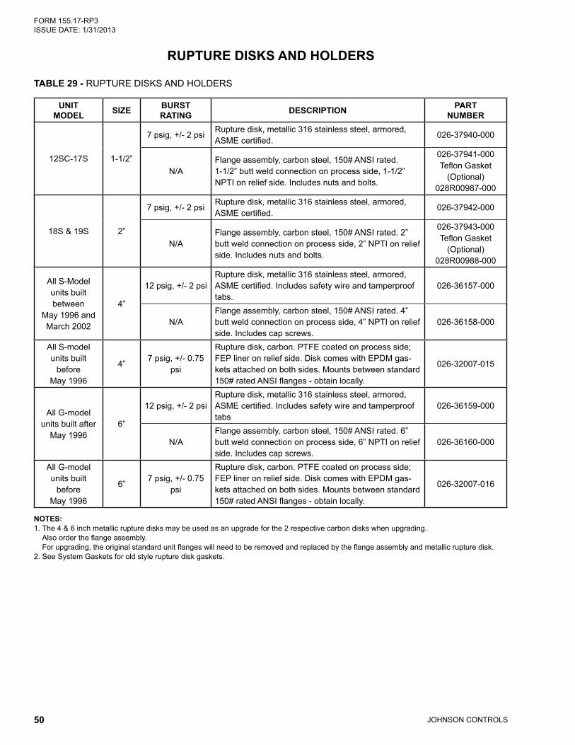
TABLE 29 - RUPTURE DISKS AND HOLDERS
UNIT MODEL SIZE BURST
RATING DESCRIPTION PART NUMBER
12SC-17S 1-1/2”
7 psig, +/- 2 psiRupture disk, metallic 316 stainless steel, armored, ASME certified.
026-37940-000
N/AFlange assembly, carbon steel, 150# ANSI rated. 1-1/2” butt weld connection on process side, 1-1/2” NPTI on relief side. Includes nuts and bolts.
026-37941-000 Teflon Gasket
(Optional) 028R00987-000
18S & 19S 2”
7 psig, +/- 2 psiRupture disk, metallic 316 stainless steel, armored, ASME certified.
026-37942-000
N/AFlange assembly, carbon steel, 150# ANSI rated. 2” butt weld connection on process side, 2” NPTI on relief side. Includes nuts and bolts.
026-37943-000 Teflon Gasket
(Optional) 028R00988-000
All S-Model units built between
May 1996 and March 2002
4”
12 psig, +/- 2 psiRupture disk, metallic 316 stainless steel, armored, ASME certified. Includes safety wire and tamperproof tabs.
026-36157-000
N/AFlange assembly, carbon steel, 150# ANSI rated. 4” butt weld connection on process side, 4” NPTI on relief side. Includes cap screws.
026-36158-000
All S-model units built
before May 1996
4”7 psig, +/- 0.75
psi
Rupture disk, carbon. PTFE coated on process side; FEP liner on relief side. Disk comes with EPDM gas-kets attached on both sides. Mounts between standard 150# rated ANSI flanges - obtain locally.
026-32007-015
All G-model units built after
May 19966”
12 psig, +/- 2 psiRupture disk, metallic 316 stainless steel, armored, ASME certified. Includes safety wire and tamperproof tabs
026-36159-000
N/AFlange assembly, carbon steel, 150# ANSI rated. 6” butt weld connection on process side, 6” NPTI on relief side. Includes cap screws.
026-36160-000
All G-model units built
before May 1996
6”7 psig, +/- 0.75
psi
Rupture disk, carbon. PTFE coated on process side; FEP liner on relief side. Disk comes with EPDM gas-kets attached on both sides. Mounts between standard 150# rated ANSI flanges - obtain locally.
026-32007-016
NOTES:1. The 4 & 6 inch metallic rupture disks may be used as an upgrade for the 2 respective carbon disks when upgrading.
Also order the flange assembly. For upgrading, the original standard unit flanges will need to be removed and replaced by the flange assembly and metallic rupture disk.
2. See System Gaskets for old style rupture disk gaskets.
RUPTURE DISKS AND HOLDERS

JOHNSON CONTROLS 51
FORM 155.17-RP3 ISSUE DATE: 1/31/2013
TABLE 30 - MISCELLANEOUS COMPONENTS
ITEM DESCRIPTION PART NUMBERSmart Purge Field Retrofit Kit1 325-32967-000Flow Switch, for use with 150# DWP Water Boxes2 024-26116-000Flow Switch, for 150#DWP Water Boxes NEMA 4 and 4x 024-15793-000Flow Switch for use with 300# DWP Water Boxes (Good for NEMA 4 and 4x) 024-12144-000Control, Differential Pressure Switch 025-30919-000Sight Glass, 2 inch Threaded 026-18004-000Absolute Pressure Gauge, Dial Type (Non-Mercury), Gauge Range 0 to 40Mm (Torr) 026-45534-000Gauge, Compound, 4” Dial, Gauge Range -760Mm Hg to 15Psig (Pi-1) 026-34443-000Gauge, Compound, 3-1/2 Inch Dial, Gauge Range 30” Vacuum to 300# Psig (Steam Pressure, Steam Units Only)
026-03952-000
Siphon (Used in Conjunction with Above Steam Pressure Gauge) 026-28384-000Tee, 1/2 Inch Threaded, Carbon Steel 023-11329-000Tee, 3/4 Inch Threaded, Carbon Steel 023-11331-000Micro Panel Heat Shield 075-17162-000Power Panel Heat Shield 075-17163-000Thermowell for Absorber, Evaporator & Condenser (Not Generator) 026-32328-000Pipe, CPVC 4” Sch 80 X 6-3/8” Long 4 - 8 NPTE One End 028-12904-0002” Half Coupling 068-00088-0001/2-13 Studs, 2-3/4” Long (Waterbox) 021-12730-0001/2-13 Studs, 3” Long 021-12731-0001/2-13 Nuts (Waterbox) 021-11154-000
NOTES:1. SmartPurge Retrofit Kit includes:
* All hardware and components (1SOL, 2SOL & PT-3) to modify purge piping. * Transducer PT-4. If unit does not have the purge tank isolation valve for PT-4, one will need to be installed. Materials for this purpose must be purchased separately. * Thermistor RT-12. If unit does not have the thermowell for RT-12, one will need to be installed. * Components to modify MicroPanel for Auto-Purge and Crystallization Cutout Safety feature. Including latest EPROM version. * Some additional items and welding will be required to install the SmartPurge Retrofit Kit. See Field Retrofit Instructions for a complete list.
2. Flow Switch can be used for either evaporator, condenser, or Hi-temp. aux. heat exchanger water loops.
MISCELLANEOUS COMPONENTS

JOHNSON CONTROLS52
FORM 155.17-RP3 ISSUE DATE: 1/31/2013
SPARE AND EMERGENCY PARTS
RECOMMENDED SPARE PARTS LISTIt is recommended that certain parts be stocked by the customer to facilitate prompt service in the event of a component failure. Spare parts will, of course, depend upon the degree of self-sufficiency required by the building owner. Larger cost items such as pump repair kits should be stocked only if there is no chiller redun-dancy at the site.
TABLE 31 - PREVENTATIVE, REGULAR AND SCHEDULED MAINTENANCE SPARE PARTS
ITEM DESCRIPTION QUANTITY PART NUMBER COMMENTS
1 Gasket, Water Box — VARIABLESee Gasket section for
applicable gaskets2 Adhesive For Water Box Gaskets 1 013-00995-000 5 oz. tube
3 Gasket, Evap. Pass Baffle 25’ 028-08547-000Units with Multiple pass boxes only
4 Inhibitor, Powder (See Notes)5 Inhibitor, Liquid
8 Hydrometer Kit, Case And Set Of 8 Hydrometers 1 026-32366-000See Service Tools
Section for contents of kit9 Cleaner, Loctite 7070 1 013-02899-000 16 fl. oz. aerosol can
10 Primer, Loctite “Primer N 7649” 1 013-01753-000 1.76 oz. bottle11 Pipe Thread Sealant, Loctite 567 1 013-02280-000 8.45 oz. tube12 Vacuum Grease, Dow Corning High Vacuum 1 011-00901-000 5.3 oz tube13 Vacuum Sealant 1 013-02882-003 4 oz. can with brush
14 Heat Conductive Compound (For Low Temp. Thermowells)
1 013-00898-000 4 oz. can
15 Heat Conductive Compound (For High Temp. Thermowells)
1 013-03083-000 16 oz. can
16 Vacuum Pump Oil 5 011-00524-004 1 gallon container17 Replacement O-Ring Kit For Spindle Valves 1 028-12271-002 for 1/2” spindle valves18 Replacement O-Ring Kit For Spindle Valves 1 028-12271-003 for 1” spindle valves19 Replacement O-Ring Kit For Spindle Valves 1 028-12271-004 for 1-1/2” spindle valves21 Ic, Real Time Clock - U16 1 031-00955-00022 Replacement Neoprene Diaphragm 1 022-09126-000 for 1/2” diaphragm valve23 Solution Sample Kit 1 028-15065-000 for Litium Bromide
NOTE:1 Purchase appropriate type of inhibitor for your unit only. See Chemicals and Compounds Section of this manual.
The table below includes parts recommended by YORK to sufficiently service the unit under normal circumstances.

JOHNSON CONTROLS 53
FORM 155.17-RP3 ISSUE DATE: 1/31/2013
RECOMMENDED EMERGENCY SPARE PARTS LIST The table below is parts recommended by YORK for Emergency chiller failures. The parts listed are for electrical and general chiller repairs in the event the chiller goes off line and needs to be repaired as soon as possible.
TABLE 32 - EMERGENCY SPARE PARTS
ITEM DESCRIPTION QTY. PART NUMBER COMMENTS
1 Temperature Sensor, 50K (for high temp. areas of unit) 1 025-29924-000 HTG and solution/dilution2 Temperature Sensor, 3K (low temp areas of unit) 1 025-29964-000 Evap & Cond water Ref. temp3 Pressure Transducer 1 025-29907-001 PT14 Fuse 1 025-29905-000 7 amp (1FU)5 I/O Expansion Board 1 031-01301-0016 Power Supply Board 1 031-01080-0007 Micro Board 1 031-01065-002 Eprom not included8 Relay Board 1 031-01199-0009 Digital Input Board (Note 1) 1 031-01621-001 Standard
10 Digital Input Board (Note 2) 1 031-01621-002 VDE11 Rupture Disk (Note 3) 1 VARIABLE12 New Motor with Pump Repair Kit (Note 4) 1 VARIABLE13 york Vacuum Pump Model 1400 V-Belt (Size 4L340) 1 028-14422-000 208-230/460/3/60 Hz14 york Vacuum Pump Model 1400 V-Belt (Size 4L350) 1 028-14423-000 380/3/50 Hz
NOTES:1. Standard wiring. 2. VDE, (Germany Wiring Code) order only if chiller meets VDE code.3. Older model units use a carbon type rupture disk mounted between standard flanges:
4 inch 026-32007-015, replacement gaskets 026-33818-000 (torque 20 ft./lbs.). 6 inch 026-32007-016, replacement gaskets 026-33819-000 (torque 20 ft./lbs.). The carbon type rupture disk will need to be replaced every three years as it becomes porous over time. Therefore, it is highly recom-mended by York to upgrade the unit rupture disks to metallic. These disks do not require a routine change out and no gaskets are required for installation. However, some unit cutting and welding will be required due to special flanges are needed.
4. Pump repair kits are available to fix virtually any pump problem that may be encountered. It is recommended that a new motor with pump repair kit be available on site for each type of pump located on the unit. Smaller units will have only two pumps while larger units will have four. New motor with pump repair kits are listed in this form for new style pumps. A kit, contents listing of what comes with each kit is also listed. If two or more pumps on the same unit have the same kit number, stock only one kit.

JOHNSON CONTROLS54
FORM 155.17-RP3 ISSUE DATE: 1/31/2013
UNIT SHIP LOOSE PARTS
The following tables are typical items that are shipped loose with each unit. Find the table with the head-ing that matches your unit for an itemized list of what should be included but shipped separately with the unit The tables do not reflect any special items or additional accessories that may be have been included with the Factory Order.
TABLE 33 - UNIT SHIP LOOSE PARTS FOR 50HZ AND 60HZ DIRECT FIRED UNITS
PART NO. SUB-ITEM PART NO. DESCRIPTION QUANTITY UOM
026-45534-000 — Pressure Gauge 4” Dial Non-Mercury 0-40 TORR 1 ea.023-04685-000 — Pipe Bush Face 1/2 - 14 NPTE x 1/4 - 18 NPTI 1 ea.023-08856-000 — Hose Clamp 11/16” minimum dia. 2 ea.021-12930-000 –– Hose Clamp 1-1/16” minimum dia. (Purge) 2 ea.375-19010-000 — Leak Test Kit 1 ea.
— 044-02982-000 Polypropylene Hydrometer Cylinder 1 ea.— 022-08885-001 Ball Valve 1/4” NPTI 1 ea.— 022-08885-005 Ball Valve 1/2” NPTI 1 ea.— 023-14616-000 Pipe Nipple 1/2” Schedule 40 Close 1 ea.— 023-03986-000 Pipe Bushing 1/2 - 14 NPTE x 1/4 - 18 NPTI 1 ea.— 023-11329-000 Tee Screw 1/2 NPTI x 1/2 NPTI x 1/2 NPTI #300 lb. 1 ea.— 023-04320-000 45 Degree Elbow Screw 1/2 NPTI x 1/2 NPTI 1 ea.— 023-14611-000 Pipe Nipple 1/2 - 14 (Schedule 40) NPTE x 4” long 1 ea.— 028-10605-000 Plastic Tube 3/8” O.D. x 1/4” I.D. (Bubble Hose) 4 ft.— 023-10280-000 Hose Clamp 1/4” minimum dia. 1 ea.
023-18224-000 — Hose Barb 1/2” NPTE x 3/4” Hose Barb 1 ea.028-13535-000 — Hose 3/4” I.D. x 1.024” O.D. (Purge Pump Inlet) 4 ft.
026-33637-0001 — Vacuum Pump, 60Hz, Model 1400 (0.9 cfm) 60Hz Units only 1 ea.026-33832-0001 — Vacuum Pump, 50Hz, Model 1400 (0.9 cfm) 50Hz Units only 1 ea.026-32007-002 — Refrigerant Removal Tank with 5/8 ID Hose and Clamps 1 ea.035-12629-000 — Label Ship Loose Packaging 1 ea.335-12694-003 — Label Valve Designations 1 ea.922-08869-001 –– Sample Valve Adapter 1 ea.
THE BELOW ITEMS ARE NOT INCLUDED IN KIT BUT ARE SHIPPED WITH EACH UNIT
024-26116-0002 —Chilled Water Flow Switch (Standard 150# DWP water boxes)
1 ea.
NOTES:1. One vacuum pump shipped per unit, part number dependent upon unit Hertz.2. One switch is included with each unit for chilled water flow. A condenser or Hot water flow switch can be supplied as an extra accessory to
the factory order. Also available are 300# DWP flow switches and Differential Pressure switches.
If any items are missing contact the factory, Customer Service dept.
Sometimes Lithium Bromide Solution, Refrigerant, and Alcohol are shipped separate from the unit. See Factory Order Sheet to determine if these items are shipped loose.

JOHNSON CONTROLS 55
FORM 155.17-RP3 ISSUE DATE: 1/31/2013
TABLE 34 - UNIT SHIP LOOSE PARTS TYPICAL BURNER SHIP LOOSE ITEMS
PART NUMBER DESCRIPTION QUANTITY UOMSee Burner Specification Sheet Thermocouple, Probe with Junction Box - 1/8” NPTE 1 EA.See Burner Specification Sheet Wire, Thermocouple - J-Type 50 FT.See Burner Specification Sheet Tubing, Aluminum, Coil for Pilot Gas 6 FT.See Burner Specification Sheet Gas Train 1 EA.See Burner Specification Sheet Pump, Oil with Drive Motor 1* EA.See Burner Specification Sheet Filter, Oil 1* EA.See Burner Specification Sheet Gauge, Oil Pressure 1* EA.
029-22435-00X** Burner Damper Assembly with FGR Connection 1 EA.See Burner Specification Sheet Braided Fiberglass Rope 13 FT.See Burner Specification Sheet Burner Damper Assembly w/ FGR Connection 1 EA.
NOTE: *Only supplied with gas / oil dual fuel burners.** 029-22435-001 – unit models 12SC thru 14S
029-22435-002 – unit models 14SC and 15S 029-22435-003 – unit models 15SL and 16S 029-22435-004 – unit models 16SL and 17S 029-22435-005 – unit models 18S and 19S
TABLE 35 - YORK VACUUM PUMP SHIP LOOSE PARTS
WELCH PART NUMBER DESCRIPTION QUANTITY UOM1407k-11 Duoseal Vacuum Pump Oil 1 qt.61-8503a Black Pipe Male To Male Adapter, 3/4”-20 X 1/2” NPTE 1 ea.67-0607 Owner’s Manual 1 ea.
41-13453 Discharge Port Dust Cap (3/4”-20 Threads) 1 ea.
NOTES:1. Above parts are applicable for both 50 and 60 Hz pumps.2. Gas ballast piping is already installed on pump from the factory.3. This item is not required for pump operation and may not be included with all pumps.

JOHNSON CONTROLS56
FORM 155.17-RP3 ISSUE DATE: 1/31/2013
TABLE 36 - UNIT SHIP LOOSE PARTS FOR 50HZ AND 60HZ STEAM FIRED UNITS
PART NO. SUB-ITEM PART NUMBER DESCRIPTION QUANTITY UOM
026-45534-000 — Pressure Gauge, Dial Type, (Non-Mercury) 0 to 40mm 1 ea.023-08856-000 — Hose Clamp 11/16” minimum dia. 2 ea.375-19010-000 — Leak Test Kit 1 ea.
— 044-02982-000 Polypropylene Hydrometer Cylinder 1 ea.— 022-08885-001 Ball Valve 1/4” NPTI 1 ea.— 022-08885-005 Ball Valve 1/2” NPTI 1 ea.— 023-14616-000 Pipe Nipple 1/2” Schedule 40 Close 1 ea.— 023-03986-000 Pipe Bushing 1/2 - 14 NPTE x 1/4 - 18 NPTI 1 ea.— 023-11329-000 Tee Screw 1/2 NPTI x 1/2 NPTI x 1/2 NPTI #300 lb. 1 ea.— 023-04320-000 45 Degree Elbow Screw 1/2 NPTI x 1/2 NPTI 1 ea.— 023-14611-000 Pipe Nipple 1/2 - 14 (schedule 40) NPTE x 4”” long 1 ea.— 028-10605-000 Plastic Tube 3/8” O.D. x 1/4” I.D. 4 ft.— 023-10280-000 Hose Clamp 1/4” minimum dia. 1 ea.
375-06889-000 — Gauge Kit 1 ea.— 026-03952-000 3-1/2” Dial Compound Gauge, Steam Pressure 1 ea.— 026-28384-000 Siphon, Ashcroft (to be used with above compound gauge) 1 ea.— 023-11103-000 1/4 -18 NPTI Pipe Coupling 1 ea.
023-18224-000 — Hose Barb 1/2” NPTE x 3/4” Hose Barb 1 ea.028-13535-000 — Hose 3/4” I.D. x 1.024” O.D. 4 ft.026-33637-0001 — Vacuum Pump, 60Hz, Model 1400 (0.9 cfm) 60Hz Units only 1 ea.026-33832-0001 — Vacuum Pump, 50Hz, Model 1400 (0.9 cfm) 50Hz Units only 1 ea.026-32007-002 — Refrigerant Removal Tank with 5/8” ID Hose and Clamps 1 ea.035-12629-000 — Label Ship Loose Packaging 1 ea.335-12694-004 — Label Valve Designations 1 ea.021-12930-000 –– Hose Clamp 1-1/16” minimum dia. 2 ea.922-08869-001 –– Sample Valve Adapter 1 ea.
THE BELOW ITEMS ARE NOT INCLUDED IN KIT BUT ARE SHIPPED WITH EACH UNIT
024-26116-0002 —Chilled Water Flow Switch (Standard 150# DWP water boxes)
1 ea.
026-20742-00X3 — Steam Control Valve 1 ea.
NOTES:1. Only one vacuum pump shipped with each unit, dependent upon unit Hertz.2. One switch is included with each unit for chilled water flow. A condenser or hot water flow switch can be supplied as an extra to the factory
order. Also available are 300# DWP flow switches and differential pressure switches.3. See Factory Order Sheet for specific Steam Control Valve part number.

JOHNSON CONTROLS 57
FORM 155.17-RP3 ISSUE DATE: 1/31/2013
NOTES

P.O. Box 1592, York, Pennsylvania USA 17405-1592 800-861-1001 Subject to change without notice. Printed in USACopyright © by Johnson Controls 2013 www.johnsoncontrols.com ALL RIGHTS RESERVEDForm 155.17-RP3 (113)Issue Date: January 31, 2013 Supersedes: 155.17-RP3 (1107)
Recommended