Embed Size (px)
Citation preview
16TJSingle-Effect Steam-Fired Absorption ChillersNominal cooling capacity 352-2461 kW
50 Hz
GB/T-19001-2000 to ISO9001/2000
Installation instructions
The cover photograph is for illustrative purposes only, and are not contractually binding.
NoTes To Users
Thank you for purchasing a Carrier/Sanyo absorption chiller.
Refer to this manual and the specification drawings before installing the absorption chiller and read this manual carefully before operating the unit. It contains instructions for the installation of the chiller.
Please utilize the chiller to its optimum performance by carrying out the recommended daily maintenance and handling instructions as well as the periodic service.
If you need any information about maintenance contracts or have any other enquiries, please contact your Carrier service agent.
�
ConTenTs
1 - InsTALLATIon ........................................................................................................................................................................ 41.1 - Environmental requirements and safety precautions ................................................................................................................. 41.2 - Safe installation ......................................................................................................................................................................... 81.3 - Delivery inspection .................................................................................................................................................................... 81.4 - Rigging ...................................................................................................................................................................................... 91.5 - Moving the chiller ..................................................................................................................................................................... 91.6 - Placing the chiller on the foundation ........................................................................................................................................ 91.7 - Levelling .................................................................................................................................................................................... 91.8 - Leak test and method of charging/removing nitrogen gas ...................................................................................................... 101.9 - Piping ....................................................................................................................................................................................... 121.10 - Field wiring ............................................................................................................................................................................ 121.11 - Purging ................................................................................................................................................................................... 121.12 - Insulation ............................................................................................................................................................................... 13
2 - TesT oPeRATIon ................................................................................................................................................................. 132.1 - External visual inspection ....................................................................................................................................................... 132.2 - Solution charge ........................................................................................................................................................................ 132.3 - Electrical check ........................................................................................................................................................................ 132.4 - Initial control board setting ...................................................................................................................................................... 142.5 - Damper setting and valve position .......................................................................................................................................... 142.6 - Purging ..................................................................................................................................................................................... 142.7 - Function test ............................................................................................................................................................................ 152.8 - Operation ................................................................................................................................................................................ 16
3 - CHeCK LIsT ........................................................................................................................................................................... 193.1 - External visual inspection ........................................................................................................................................................ 193.2 - Verify the field wiring and wiring of palladium cell heater ..................................................................................................... 193.3 - Check of motor insulation resistance ....................................................................................................................................... 193.4 - Check of control board safety and switch settings .................................................................................................................. 203.5 - Check of purge pump............................................................................................................................................................... 203.6 - Verify auxiliary equipment ...................................................................................................................................................... 203.7 - Bubble test ............................................................................................................................................................................... 203.8 - Verify valve opening status and switch positions .................................................................................................................... 203.9 - Verify control board parameters .............................................................................................................................................. 213.10 - Pre operation checks .............................................................................................................................................................. 213.11 - Operation and data record ...................................................................................................................................................... 223.12 - Sample of absorbent taken (for analysis) .............................................................................................................................. 23
exhibits
TA - Precautions for use ................................................................................................................................................................ 24
TB - shipping dimensions/Centre of gravity location ............................................................................................................ 25-26
TC - Foundation dimensions ......................................................................................................................................................... 27
TD - not used
Te - Typical piping diagram/Water treatment/Dimensional drawings ............................................................................... 28-37
TF - Wire sizes/Field wiring/Wiring diagram ........................................................................................................................ 38-41
TG - Insulation area ....................................................................................................................................................................... 42
TH - LiBr solution material safety data sheet ........................................................................................................................ 43-45
TI - Character recognition table/operation board parameter verification .......................................................................... 46-49
TJ - Flow diagram and damper and valve position .................................................................................................................... 50
�
1 - INsTALLATIoN
1.1 - environmental requirements and safety precautions
1.1.1 - Installation considerationsThe 16TJ absorption chiller is designed for indoor installation in a machine room. The protection rating of the chiller is IP40. Room temperature should be maintained between 5°C and 40°C to protect against solution crystallization during chiller shutdown. The humidity in the machine room must be kept below 90%.
1.1.2 - Field wiringCE machines should be connected to a power source that complies with overvoltage category III (IEC 60664). All other wiring should comply with overvoltage category II.
1.1.3 - AltitudePlease install the absorption chiller at a maximum height of 1000 m above sea level. If the location is higher than 1000 m above sea level, please contact your local Carrier office.
1.1.4 - safety precautions• Before operating this chiller, first carefully read the
following instructions.• All precautions are classified as either WARNING or
CAUTION.
WARNING: Failure to observe this instruction may result in serious injury or death.
CAUTION : Failure to observe this instruction may cause an injury or failure of chiller. Depending on circumstances, this may result in serious injury or death.
This symbol denotes danger, a warning or a caution. The illustration in this symbol shows the specific description of the item.
This symbol prohibits an action. The illustration next to this symbol shows the specific description of the item.
This symbol instructs an action to be done. The illustration in this symbol shows the specific description of the item.
• After reading this manual, it should be kept in a safe place to be available for any user at any time.
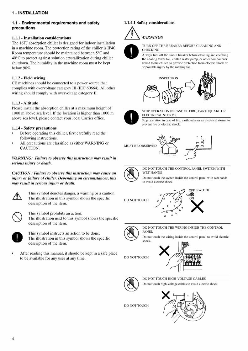
TURN OFF THE BREAKER BEFORE CLEANING AND CHECKING
Always turn off the circuit breaker before cleaning and checking the cooling tower fan, chilled water pump, or other components linked to the chiller, to provide protection from electric shock or or possible injury by the rotating fan.
INSPECTION
DO NOT TOUCH THE CONTROL PANEL SWITCH WITH WET HANDS
Do not touch the switch inside the control panel with wet hands to avoid electric shock.
STOP OPERATION IN CASE OF FIRE, EARTHQUAKE OR ELECTRICAL STORMS
Stop operation in case of fire, earthquake or an electrical storm, to prevent fire or electric shock.
DO NOT TOUCH THE WIRING INSIDE THE CONTROL PANEL
Do not touch the wiring inside the control panel to avoid electric shock.
SWITCH
DO NOT TOUCH
DO NOT TOUCH
DO NOT TOUCH HIGH-VOLTAGE CABLES
Do not touch high-voltage cables to avoid electric shock.
DO NOT TOUCH
MUST BE OBSERVED
1.1.4.1 safety considerations
WARNINGS
�
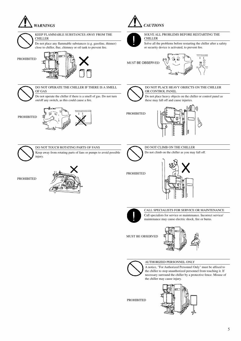
DO NOT OPERATE THE CHILLER IF THERE IS A SMELL OF GAS
Do not operate the chiller if there is a smell of gas. Do not turn on/off any switch, as this could cause a fire.
KEEP FLAMMABLE SUBSTANCES AWAY FROM THE CHILLER
Do not place any flammable substances (e.g. gasoline, thinner) close to chiller, flue, chimney or oil tank to prevent fire.
DO NOT TOUCH ROTATING PARTS OF FANS
Keep away from rotating parts of fans or pumps to avoid possible injury.
PROHIBITED
PROHIBITED
PROHIBITED
SOLVE ALL PROBLEMS BEFORE RESTARTING THE CHILLER
Solve all the problems before restarting the chiller after a safety or security device is activated, to prevent fire.
MUSt bE obSErVED
DO NOT PLACE HEAVY OBJECTS ON THE CHILLER OR CONTROL PANEL
Do not place heavy objects on the chiller or control panel as these may fall off and cause injuries.
PROHIBITED
DO NOT CLIMB ON THE CHILLER
Do not climb on the chiller as you may fall off.
PROHIBITED
CALL SPECIALISTS FOR SERVICE OR MAINTENANCE
Call specialists for service or maintenance. Incorrect service/ maintenance may cause electric shock, fire or burns.
MUST BE OBSERVED
AUTHORIZED PERSONNEL ONLY
A notice, "For Authorized Personnel Only" must be affixed to the chiller to stop unauthorized personnel from touching it. If necessary surround the chiller by a protective fence. Misuse of the chiller may cause injury.
PROHIBITED
WARNINGS CAUTIONS
�
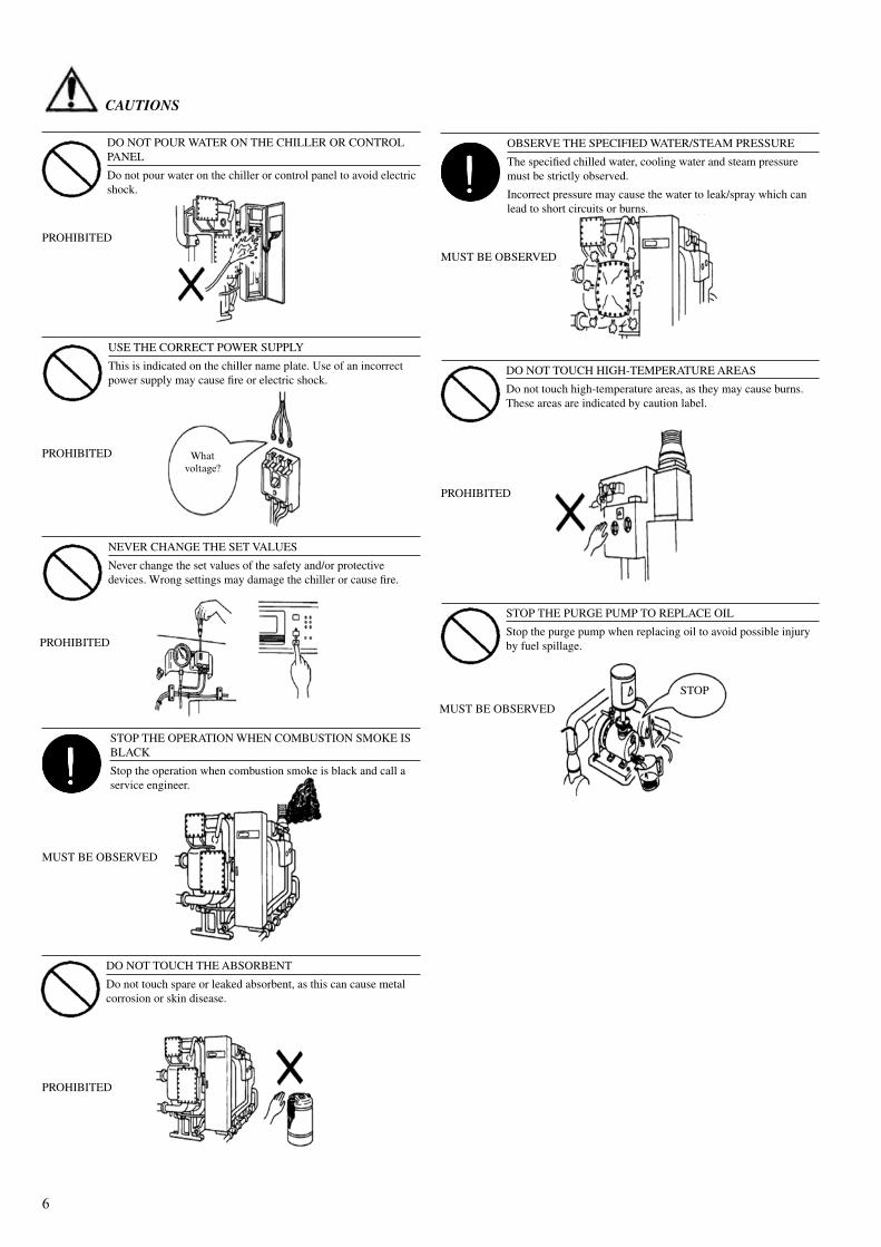
DO NOT POUR WATER ON THE CHILLER OR CONTROL PANEL
Do not pour water on the chiller or control panel to avoid electric shock.
PROHIBITED
USE THE CORRECT POWER SUPPLY
This is indicated on the chiller name plate. Use of an incorrect power supply may cause fire or electric shock.
PROHIBITED
NEVER CHANGE THE SET VALUES
Never change the set values of the safety and/or protective devices. Wrong settings may damage the chiller or cause fire.
PROHIBITED
STOP THE OPERATION WHEN COMBUSTION SMOKE IS BLACK
Stop the operation when combustion smoke is black and call a service engineer.
MUST BE OBSERVED
DO NOT TOUCH THE ABSORBENT
Do not touch spare or leaked absorbent, as this can cause metal corrosion or skin disease.
PROHIBITED
OBSERVE THE SPECIFIED WATER/STEAM PRESSURE
The specified chilled water, cooling water and steam pressure must be strictly observed.
Incorrect pressure may cause the water to leak/spray which can lead to short circuits or burns.
MUST BE OBSERVED
PROHIBITED
STOP THE PURGE PUMP TO REPLACE OIL
Stop the purge pump when replacing oil to avoid possible injury by fuel spillage.
MUST BE OBSERVED
DO NOT TOUCH HIGH-TEMPERATURE AREAS
Do not touch high-temperature areas, as they may cause burns. These areas are indicated by caution label.
Whatvoltage?
STOP
CAUTIONS
�
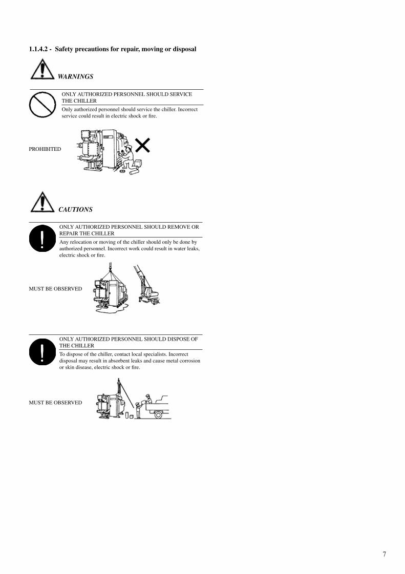
ONLY AUTHORIZED PERSONNEL SHOULD SERVICE THE CHILLER
Only authorized personnel should service the chiller. Incorrect service could result in electric shock or fire.
PROHIBITED
1.1.4.2 - safety precautions for repair, moving or disposal
ONLY AUTHORIZED PERSONNEL SHOULD REMOVE OR REPAIR THE CHILLER
Any relocation or moving of the chiller should only be done by authorized personnel. Incorrect work could result in water leaks, electric shock or fire.
MUST BE OBSERVED
ONLY AUTHORIZED PERSONNEL SHOULD DISPOSE OF THE CHILLER
To dispose of the chiller, contact local specialists. Incorrect disposal may result in absorbent leaks and cause metal corrosion or skin disease, electric shock or fire.
MUST BE OBSERVED
WARNINGS
CAUTIONS
�
1.2 - safe installation
Equipment installation must be carried out by a qualified installer, taking the appropriate safety measures.Ensure that unauthorized people cannot enter the installation site during installation.
1.3 - Delivery inspection
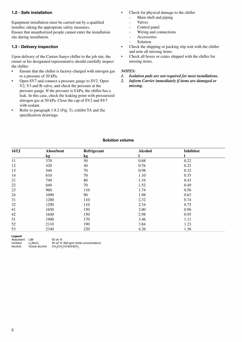
Upon delivery of the Carrier-Sanyo chiller to the job site, the owner or his designated representative should carefully inspect the chiller:• Ensure that the chiller is factory-charged with nitrogen gas
to a pressure of 20 kPa.• Open SV7 and connect a pressure gauge to SV2. Open
V2, V3 and B-valve, and check the pressure at the pressure gauge. If the pressure is 0 kPa, the chiller has a leak. In this case, check the leaking point with pressurized nitrogen gas at 50 kPa. Close the cap of SV2 and SV7 with sealant.
• Refer to paragraph 1.8.2 (Fig. 5), exhibit TA and the specification drawings.
solution volume 16TJ Absorbent Refrigerant Alcohol Inhibitor kg kg l l11 370 50 0.68 0.2212 420 40 0.76 0.2513 540 70 0.98 0.3214 610 70 1.10 0.3521 740 80 1.34 0.4322 840 70 1.52 0.4923 960 110 1.74 0.5624 1090 90 1.98 0.6331 1280 110 2.32 0.7432 1290 110 2.34 0.7541 1650 150 3.00 0.9642 1640 150 2.98 0.9551 1900 170 3.46 1.1152 2110 190 3.84 1.2353 2340 220 4.26 1.36
LegendAbsorbent Libr 50 wt %Inhibitor Li2Moo4 20 wt % 300 ppm (total concentration)Alcohol octyle alcohol CH3(CH2)
5CH(oH)CH3
• Check for physical damage to the chiller - Main shell and piping - Valves - Control panel - Wiring and connections - Accessories - Solution• Check the shipping or packing slip sent with the chiller
and note all missing items.• Check all boxes or crates shipped with the chiller for
missing items.
NOTES:1. Isolation pads are not required for most installations.2. Inform Carrier immediately if items are damaged or
missing.
�
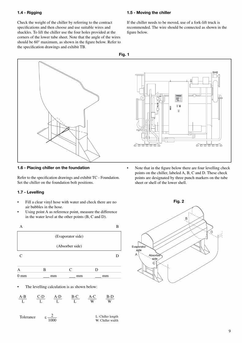
1.4 - rigging
Check the weight of the chiller by referring to the contract specifications and then choose and use suitable wires and shackles. To lift the chiller use the four holes provided at the corners of the lower tube sheet. Note that the angle of the wires should be 60° maximum, as shown in the figure below. Refer to the specification drawings and exhibit TB.
1.6 - Placing chiller on the foundation
Refer to the specification drawings and exhibit TC - Foundation. Set the chiller on the foundation bolt positions.
1.7 - Levelling
• Fill a clear vinyl hose with water and check there are no air bubbles in the hose.
• Using point A as reference point, measure the difference in the water level at the other points (B, C and D).
A B
(Evaporator side)
(Absorber side)
C D
A B C D
0 mm ___ mm ___ mm ___ mm
• The levelling calculation is as shown below:
A-B C-D A-D B-C A-C B-D L L L L W W
L: Chiller lengthW: Chiller width
≤ 21000
Fig. 1
Evaporatorside
Absorberside
Fig. 2
1.5 - Moving the chiller
If the chiller needs to be moved, use of a fork-lift truck is recommended. The wire should be connected as shown in the figure below.
• Note that in the figure below there are four levelling check points on the chiller, labeled A, B, C and D. These check points are designated by three punch markers on the tube sheet or shell of the lower shell.
Tolerance
10
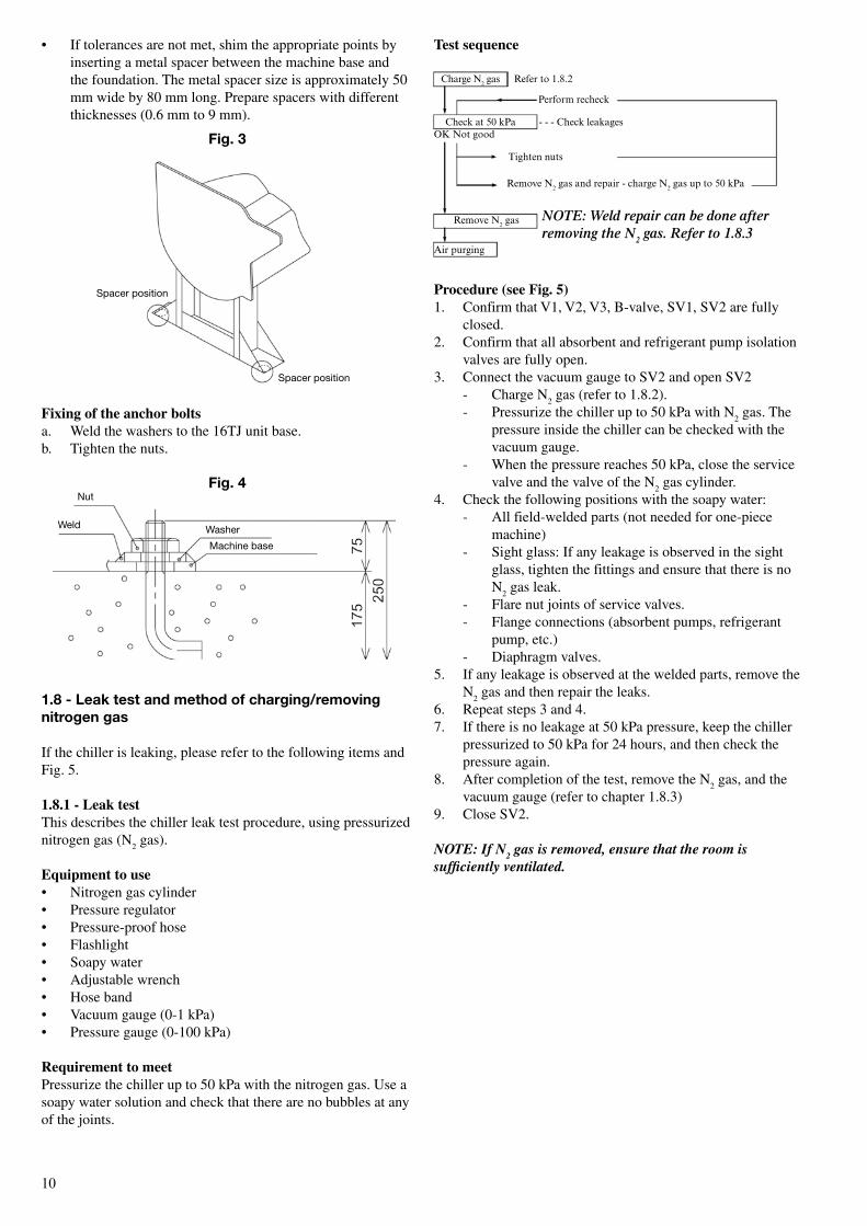
Test sequence
Procedure (see Fig. 5)1. Confirm that V1, V2, V3, B-valve, SV1, SV2 are fully
closed.2. Confirm that all absorbent and refrigerant pump isolation
valves are fully open.3. Connect the vacuum gauge to SV2 and open SV2 - Charge N
2 gas (refer to 1.8.2).
- Pressurize the chiller up to 50 kPa with N2 gas. The
pressure inside the chiller can be checked with the vacuum gauge.
- When the pressure reaches 50 kPa, close the service valve and the valve of the N
2 gas cylinder.
4. Check the following positions with the soapy water: - All field-welded parts (not needed for one-piece
machine) - Sight glass: If any leakage is observed in the sight
glass, tighten the fittings and ensure that there is no N
2 gas leak.
- Flare nut joints of service valves. - Flange connections (absorbent pumps, refrigerant
pump, etc.) - Diaphragm valves.5. If any leakage is observed at the welded parts, remove the
N2 gas and then repair the leaks.
6. Repeat steps 3 and 4.7. If there is no leakage at 50 kPa pressure, keep the chiller
pressurized to 50 kPa for 24 hours, and then check the pressure again.
8. After completion of the test, remove the N2 gas, and the
vacuum gauge (refer to chapter 1.8.3) 9. Close SV2.
NOTE: If N2 gas is removed, ensure that the room is sufficiently ventilated.
Spacer position
Spacer position
• If tolerances are not met, shim the appropriate points by inserting a metal spacer between the machine base and the foundation. The metal spacer size is approximately 50 mm wide by 80 mm long. Prepare spacers with different thicknesses (0.6 mm to 9 mm).
Fixing of the anchor boltsa. Weld the washers to the 16TJ unit base.b. Tighten the nuts.
1.8 - Leak test and method of charging/removing nitrogen gas
If the chiller is leaking, please refer to the following items and Fig. 5.
1.8.1 - Leak testThis describes the chiller leak test procedure, using pressurized nitrogen gas (N
2 gas).
equipment to use• Nitrogen gas cylinder• Pressure regulator• Pressure-proof hose• Flashlight• Soapy water• Adjustable wrench• Hose band• Vacuum gauge (0-1 kPa)• Pressure gauge (0-100 kPa)
Requirement to meetPressurize the chiller up to 50 kPa with the nitrogen gas. Use a soapy water solution and check that there are no bubbles at any of the joints.
Nut
Weld Washer
Machine base
Fig. 4
NOTE: Weld repair can be done after removing the N
2 gas. Refer to 1.8.3
Fig. 3
Charge N2 gas Refer to 1.�.2
Perform recheck
Check at �0 kPa - - - Check leakagesOK Not good
Tighten nuts
Remove N2 gas and repair - charge N2 gas up to �0 kPa
Remove N2 gas
Air purging
11
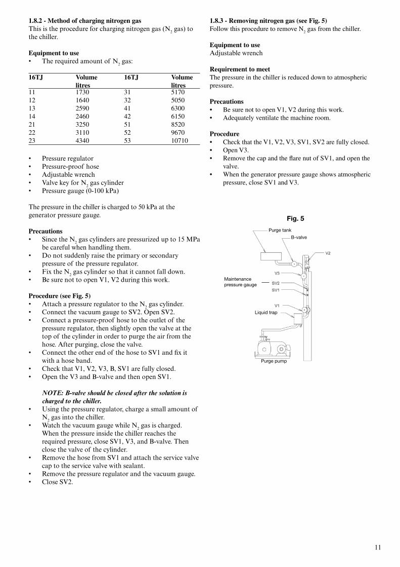
1.8.2 - Method of charging nitrogen gasThis is the procedure for charging nitrogen gas (N2 gas) to the chiller.
equipment to use• The required amount of N2 gas: 16TJ Volume 16TJ Volume litres litres11 1730 31 517012 1640 32 505013 2590 41 630014 2460 42 615021 3250 51 852022 3110 52 967023 4340 53 10710
• Pressure regulator• Pressure-proof hose• Adjustable wrench• Valve key for N2 gas cylinder• Pressure gauge (0-100 kPa)
The pressure in the chiller is charged to �0 kPa at the generator pressure gauge.
Precautions• Since the N2 gas cylinders are pressurized up to 1� MPa
be careful when handling them.• Do not suddenly raise the primary or secondary
pressure of the pressure regulator.• Fix the N2 gas cylinder so that it cannot fall down.• Be sure not to open V1, V2 during this work.
Procedure (see Fig. 5)• Attach a pressure regulator to the N2 gas cylinder.• Connect the vacuum gauge to SV2. Open SV2.• Connect a pressure-proof hose to the outlet of the
pressure regulator, then slightly open the valve at the top of the cylinder in order to purge the air from the hose. After purging, close the valve.
• Connect the other end of the hose to SV1 and fix it with a hose band.
• Check that V1, V2, V�, B, SV1 are fully closed.• Open the V� and B-valve and then open SV1.
Note: B-valve should be closed after the solution is charged to the chiller.
• Using the pressure regulator, charge a small amount of N2 gas into the chiller.
• Watch the vacuum gauge while N2 gas is charged. When the pressure inside the chiller reaches the required pressure, close SV1, V�, and B-valve. Then close the valve of the cylinder.
• Remove the hose from SV1 and attach the service valve cap to the service valve with sealant.
• Remove the pressure regulator and the vacuum gauge.• Close SV2.
1.8.3 - Removing nitrogen gas (see Fig. 5)Follow this procedure to remove N
2 gas from the chiller.
equipment to useAdjustable wrench
Requirement to meetThe pressure in the chiller is reduced down to atmospheric pressure.
Precautions• Be sure not to open V1, V2 during this work.• Adequately ventilate the machine room.
Procedure• Check that the V1, V2, V3, SV1, SV2 are fully closed.• Open V3.• Remove the cap and the flare nut of SV1, and open the
valve.• When the generator pressure gauge shows atmospheric
pressure, close SV1 and V3.
Fig. 5
Purge tank
Liquid trap
b-valve
Purge pump
Maintenance pressure gauge
12
1.9 - Piping
1.9.1 - Connect each pipe according to exhibit Te and the specification drawings.• Make all necessary connections to the building chilled and
cooling water systems. Ensure that all piping is adequately supported and that no strain is placed on the chiller nozzles and connecting flanges.
• Provide adequate temperature and pressure sockets or taps on all supply and return piping.
1.9.2 - FlushingAll water system pipes must be flushed before the water is circulated in the chiller.
1.10 - Field wiring
Ce markingPower supply connections should be in accordance with CE and comply with overvoltage category III (IEC 60664). All other connections should be in accordance with overvoltage category II. All wiring must be in accordance with CE requirements.
• Refer to exhibit TF and the specification drawings for wiring connections.
• Supply power to the steam control valve and steam shut-off valve.
• Refer to chapter 2.3 - Electrical check.• A properly qualified electrician should carry out the
electrical wiring.
1.11 - Purging (see Fig. 5)
• Ensure that the power supply is continuous.• Remove nitrogen gas (refer to chapter 1.8.3.)• Fill the purge oil pump to the centre of the red mark of
purge pump level gauge.• Turn on the control panel main breaker and the purge
pump switch. Check the direction of rotation. If the direction is wrong, turn off the power supply to the chiller.
• Then change any two of the wires of main power supply source. The chiller was connected with all wires meeting the same phase. Run the purge pump continuously.
• Connect the vacuum gauge (1 kPa) to SV2. - Open SV2. - Open V1, V3, and B-valve to purge the chiller. - After one hour open V2.• Operate the purge pump until the vacuum gauge shows 0.5
kPa. Refer to the following table. 16TJ Time11-14 5 hours21-32 12 hours41-53 24 hours
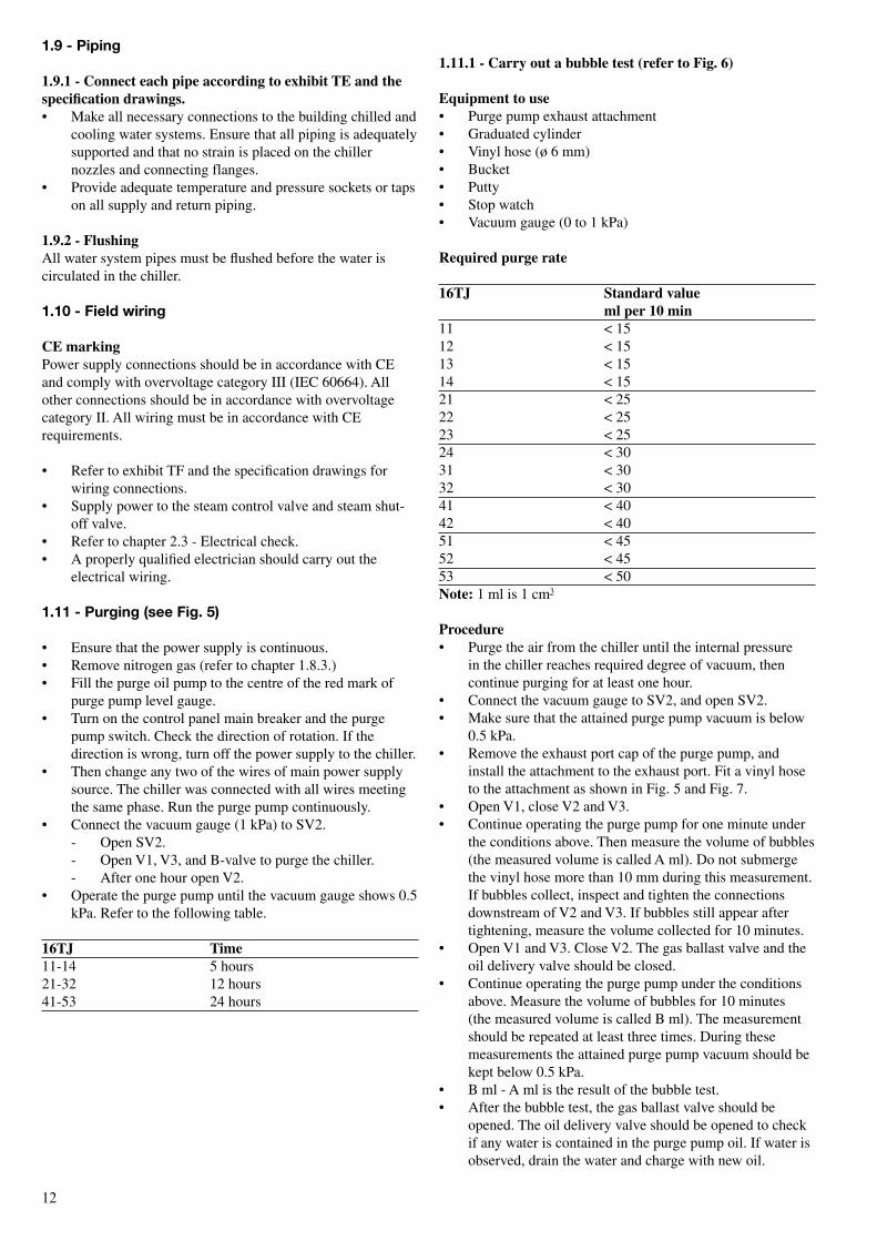
1.11.1 - Carry out a bubble test (refer to Fig. 6)
equipment to use• Purge pump exhaust attachment• Graduated cylinder• Vinyl hose (ø 6 mm)• Bucket• Putty• Stop watch• Vacuum gauge (0 to 1 kPa)
Required purge rate 16TJ standard value ml per 10 min11 < 1512 < 1513 < 1514 < 1521 < 2522 < 2523 < 2524 < 3031 < 3032 < 3041 < 4042 < 4051 < 4552 < 4553 < 50note: 1 ml is 1 cm3
Procedure• Purge the air from the chiller until the internal pressure
in the chiller reaches required degree of vacuum, then continue purging for at least one hour.
• Connect the vacuum gauge to SV2, and open SV2.• Make sure that the attained purge pump vacuum is below
0.5 kPa.• Remove the exhaust port cap of the purge pump, and
install the attachment to the exhaust port. Fit a vinyl hose to the attachment as shown in Fig. 5 and Fig. 7.
• Open V1, close V2 and V3.• Continue operating the purge pump for one minute under
the conditions above. Then measure the volume of bubbles (the measured volume is called A ml). Do not submerge the vinyl hose more than 10 mm during this measurement. If bubbles collect, inspect and tighten the connections downstream of V2 and V3. If bubbles still appear after tightening, measure the volume collected for 10 minutes.
• Open V1 and V3. Close V2. The gas ballast valve and the oil delivery valve should be closed.
• Continue operating the purge pump under the conditions above. Measure the volume of bubbles for 10 minutes (the measured volume is called B ml). The measurement should be repeated at least three times. During these measurements the attained purge pump vacuum should be kept below 0.5 kPa.
• B ml - A ml is the result of the bubble test. • After the bubble test, the gas ballast valve should be
opened. The oil delivery valve should be opened to check if any water is contained in the purge pump oil. If water is observed, drain the water and charge with new oil.
1�
1
3
2
4
5
6
7
9
10
11
8
10 mm
12
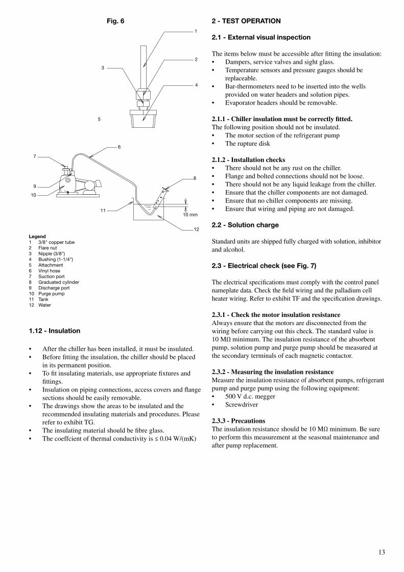
Fig. 6
Legend1 3/8" copper tube2 Flare nut3 Nipple (3/8")4 bushing (1-1/4")5 Attachment6 Vinyl hose7 Suction port8 Graduated cylinder9 Discharge port10 Purge pump11 tank12 Water
2 - TesT oPerATIoN
2.1 - external visual inspection
The items below must be accessible after fitting the insulation:• Dampers, service valves and sight glass.• Temperature sensors and pressure gauges should be
replaceable.• Bar-thermometers need to be inserted into the wells
provided on water headers and solution pipes.• Evaporator headers should be removable.
2.1.1 - Chiller insulation must be correctly fitted.The following position should not be insulated.• The motor section of the refrigerant pump • The rupture disk
2.1.2 - Installation checks• There should not be any rust on the chiller. • Flange and bolted connections should not be loose.• There should not be any liquid leakage from the chiller.• Ensure that the chiller components are not damaged.• Ensure that no chiller components are missing.• Ensure that wiring and piping are not damaged.
2.2 - solution charge
Standard units are shipped fully charged with solution, inhibitor and alcohol.
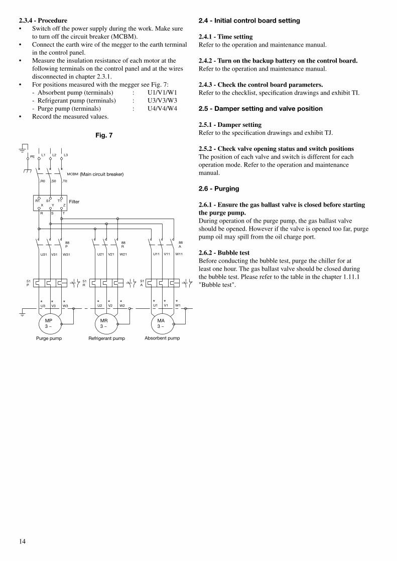
2.3 - electrical check (see Fig. 7)
The electrical specifications must comply with the control panel nameplate data. Check the field wiring and the palladium cell heater wiring. Refer to exhibit TF and the specification drawings.
2.3.1 - Check the motor insulation resistanceAlways ensure that the motors are disconnected from the wiring before carrying out this check. The standard value is 10 MΩ minimum. The insulation resistance of the absorbent pump, solution pump and purge pump should be measured at the secondary terminals of each magnetic contactor.
2.3.2 - Measuring the insulation resistanceMeasure the insulation resistance of absorbent pumps, refrigerant pump and purge pump using the following equipment:• 500 V d.c. megger• Screwdriver
2.3.3 - PrecautionsThe insulation resistance should be 10 MΩ minimum. Be sure to perform this measurement at the seasonal maintenance and after pump replacement.
1.12 - Insulation
• After the chiller has been installed, it must be insulated. • Before fitting the insulation, the chiller should be placed
in its permanent position.• To fit insulating materials, use appropriate fixtures and
fittings.• Insulation on piping connections, access covers and flange
sections should be easily removable.• The drawings show the areas to be insulated and the
recommended insulating materials and procedures. Please refer to exhibit TG.
• The insulating material should be fibre glass.• The coeffcient of thermal conductivity is ≤ 0.04 W/(mK)
1�
‚r0 ‚S0 ‚t0
PE
88A
P51
r51
3 toMA
3 toMP
3 toMr
r88
MCbM
P88
51A
U11 V11 W11
U1 V1 W1* * *
U21 V21 W21
U2 V2 W2* * *
U31 V31 W31
U3 V3 W3* * *
r S t
X Y Zr1 S1 t1
L1 L2 L3
Purge pump refrigerant pump Absorbent pump
Fig. 7
Filter
(Main circuit breaker)
2.4 - Initial control board setting
2.4.1 - Time settingRefer to the operation and maintenance manual.
2.4.2 - Turn on the backup battery on the control board.Refer to the operation and maintenance manual.
2.4.3 - Check the control board parameters.Refer to the checklist, specification drawings and exhibit TI.
2.5 - Damper setting and valve position
2.5.1 - Damper settingRefer to the specification drawings and exhibit TJ.
2.5.2 - Check valve opening status and switch positionsThe position of each valve and switch is different for each operation mode. Refer to the operation and maintenance manual.
2.6 - Purging
2.6.1 - ensure the gas ballast valve is closed before starting the purge pump.During operation of the purge pump, the gas ballast valve should be opened. However if the valve is opened too far, purge pump oil may spill from the oil charge port.
2.6.2 - Bubble testBefore conducting the bubble test, purge the chiller for at least one hour. The gas ballast valve should be closed during the bubble test. Please refer to the table in the chapter 1.11.1 "Bubble test".
2.3.4 - Procedure• Switch off the power supply during the work. Make sure
to turn off the circuit breaker (MCBM).• Connect the earth wire of the megger to the earth terminal
in the control panel.• Measure the insulation resistance of each motor at the
following terminals on the control panel and at the wires disconnected in chapter 2.3.1.
• For positions measured with the megger see Fig. 7: - Absorbent pump (terminals) : U1/V1/W1 - Refrigerant pump (terminals) : U3/V3/W3 - Purge pump (terminals) : U4/V4/W4 • Record the measured values.
MP3 ~
Mr3 ~
MA3 ~
1�
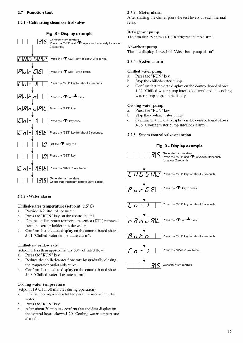
Generator temperaturePress the "SEt" and " "keys simultaneously for about 2 seconds.
Press the " SEt" key for about 2 seconds.
Press the " SEt" key 3 times.
Press the "SEt" key for about 2 seconds.
Press the " " or " " key.
Press the "SEt" key.
Press the " " key once.
Press the "SEt" key for about 2 seconds.
Set the " " key to 0.
Press the "SEt" key.
Press the "bACK" key twice.
Generator temperatureCheck that the steam control valve closes.
Fig. 8 - Display example
Generator temperaturePress the "SEt" and " "keys simultaneouslyfor about 2 seconds.
Press the "SEt" key for about 2 seconds.
Press the " " key 3 times.
Press the "SEt" key for about 2 seconds.
Press the " " or " " key.
Press the "SEt" key for about 2 seconds.
Press the "bACK" key twice.
Generator temperature
Fig. 9 - Display example
2.7.3 - Motor alarmAfter starting the chiller press the test levers of each thermal relay.
Refrigerant pumpThe data display shows J-10 "Refrigerant pump alarm".
Absorbent pumpThe data display shows J-04 "Absorbent pump alarm".
2.7.4 - system alarm
Chilled water pumpa. Press the "RUN" key.b. Stop the chilled-water pump.c. Confirm that the data display on the control board shows
J-02 "Chilled-water pump interlock alarm" and the cooling water pump stops immediately.
Cooling water pumpa. Press the "RUN" key.b. Stop the cooling water pump.c. Confirm that the data display on the control board shows
J-06 "Cooling water pump interlock alarm".
2.7.5 - steam control valve operation
2.7.2 - Water alarm
Chilled-water temperature (setpoint: 2.5°C)a. Provide 1-2 litres of ice water.b. Press the "RUN" key on the control board.c. Dip the chilled-water temperature sensor (DT1) removed
from the sensor holder into the water.d. Confirm that the data display on the control board shows
J-01 "Chilled water temperature alarm".
Chilled-water flow rate(setpoint: less than approximately 50% of rated flow)a. Press the "RUN" keyb. Reduce the chilled-water flow rate by gradually closing
the evaporator outlet side valve.c. Confirm that the data display on the control board shows
J-03 "Chilled water flow rate alarm".
Cooling water temperature(setpoint 19°C for 30 minutes during operation)a. Dip the cooling water inlet temperature sensor into the
water.b. Press the "RUN" keyc. After about 30 minutes confirm that the data display on
the control board shows J-20 "Cooling water temperature alarm".
2.7 - Function test
2.7.1 - Calibrating steam control valves
1�
2.8 - operation
2.8.1 - Test operation Before starting the chiller, check the opening of the valves and the damper position. Refer to exhibit TJ.
Usually the units are factory-adjusted, but when assembling them on site or operating them for the first time, the following adjusting procedure should be taken.
2.8.2 - operation and data recordRecord data three times at 10 to 15-minute intervals during stable operating conditions.
Tools required to record operation data• Thermometer • Pressure gauge• Stop watch • Solution sampling tool • Gravimeter • Concentration table as attached
2.8.3 - Absorbent samplingSampling should be carried out as follows: • Sampling of diluted solution• Sampling from SV4, located on the absorbent pump outlet• Solution should be sampled twice. The sample quantity is
100 ml. The second sample should be used for analysis.
Mark Item Criteria ActionB1* Hammer sound No hammer sound Close the diluted solution damper little by little (heat exchanger) (angle ± 2°)B2* Hammer sound No hammer sound Install the check valve to the steam drain piping (steam drain piping)
* During the adjustment, service engineers must stay near the chiller, because it is running with the steam control valve forced open.
1�
1,40
1,45
1,50
1,55
1,60
1,65
1,70
1,75
1,80
1,85
0 10 20 30 40 50 60 70 80 90 100
65%
60%
55%
50%
45%
rel
ativ
e d
ensi
ty (k
g/m
3 ) x
10-3
Con
cent
ratio
n (%
)
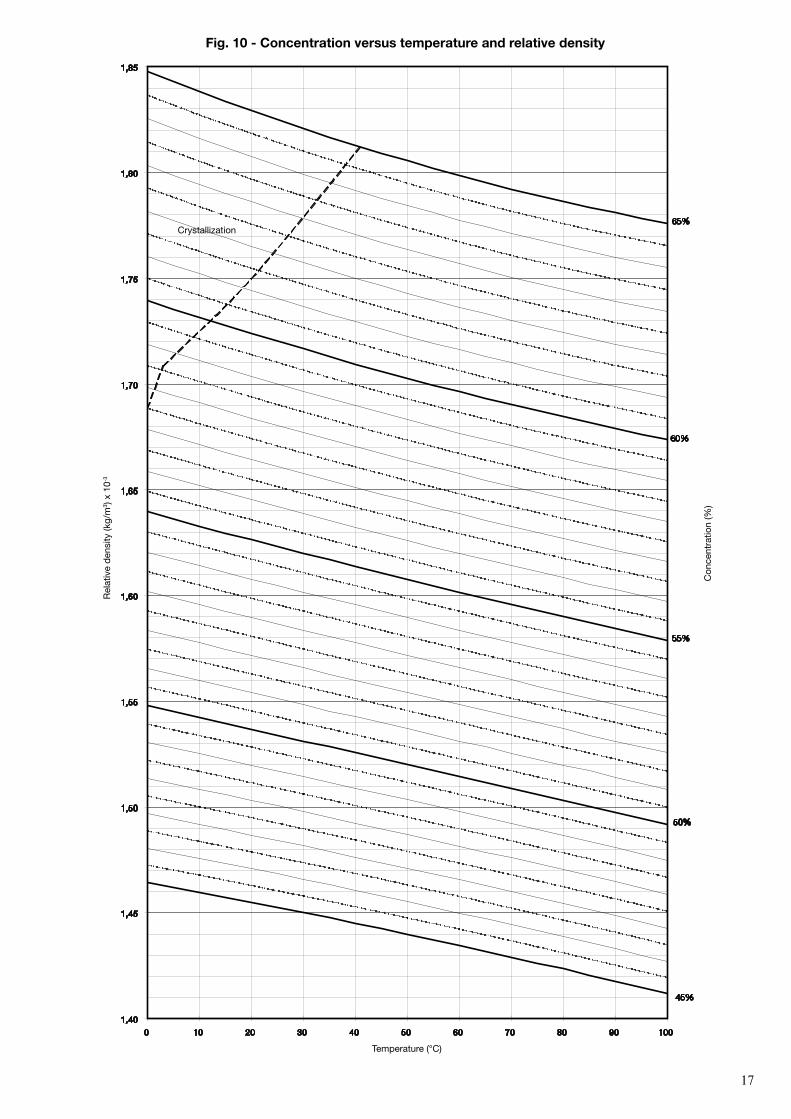
Fig. 10 - Concentration versus temperature and relative density
temperature (°C)
Crystallization
1�
0,95
1,00
1,05
1,10
1,15
1,20
1,25
1,30
1,35
1,40
1,45
1,50
0 10 20 30 40 50 60 70 80 90 100
45%
40%
35%
30%
25%
20%
15%
10%
5%
0%
rel
ativ
e d
ensi
ty (k
g/m
3 ) x
10-3
Con
cent
ratio
n (%
)
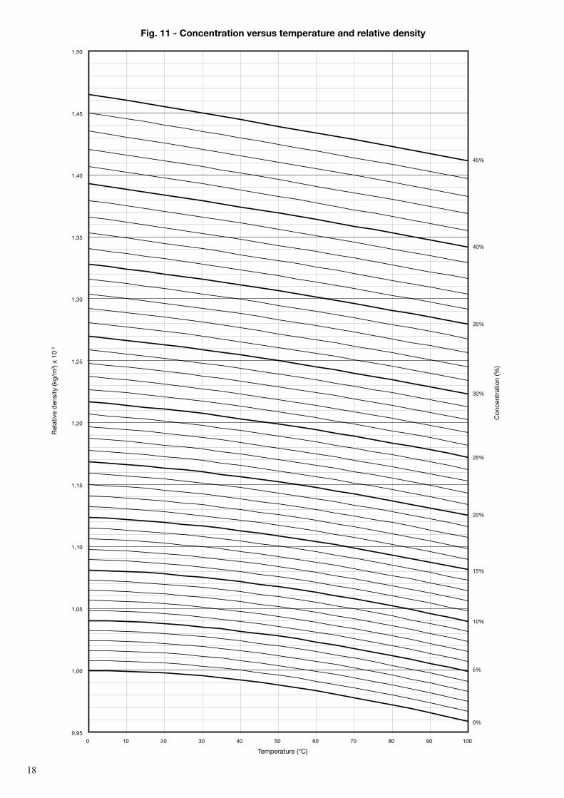
Fig. 11 - Concentration versus temperature and relative density
temperature (°C)
1�1�
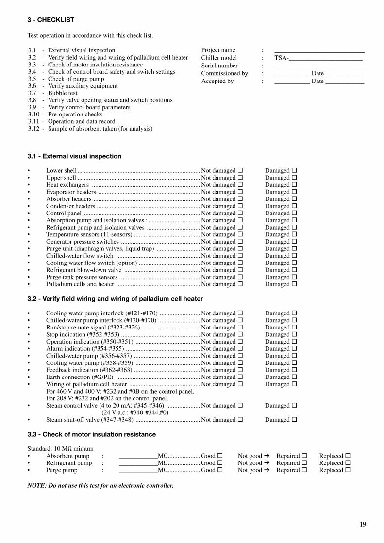
3.1 - external visual inspection
• Lower shell ............................................................................ Not damaged ® Damaged ®• Upper shell ............................................................................ Not damaged ® Damaged ®• Heat exchangers ................................................................... Not damaged ® Damaged ®• Evaporator headers ............................................................... Not damaged ® Damaged ®• Absorber headers .................................................................. Not damaged ® Damaged ®• Condenser headers ................................................................ Not damaged ® Damaged ®• Control panel ........................................................................ Not damaged ® Damaged ®• Absorption pump and isolation valves : ................................ Not damaged ® Damaged ®• Refrigerant pump and isolation valves ................................. Not damaged ® Damaged ®• Temperature sensors (11 sensors) ......................................... Not damaged ® Damaged ®• Generator pressure switches ................................................. Not damaged ® Damaged ®• Purge unit (diaphragm valves, liquid trap) ........................... Not damaged ® Damaged ®• Chilled-water flow switch .................................................... Not damaged ® Damaged ®• Cooling water flow switch (option) ...................................... Not damaged ® Damaged ®• Refrigerant blow-down valve ............................................... Not damaged ® Damaged ®• Purge tank pressure sensors .................................................. Not damaged ® Damaged ®• Palladium cells and heater .................................................... Not damaged ® Damaged ®
3.2 - Verify field wiring and wiring of palladium cell heater
• Cooling water pump interlock (#121-#170) ......................... Not damaged ® Damaged ®• Chilled-water pump interlock (#120-#170) .......................... Not damaged ® Damaged ®• Run/stop remote signal (#323-#326) .................................... Not damaged ® Damaged ®• Stop indication (#352-#353) ................................................. Not damaged ® Damaged ®• Operation indication (#350-#351) ........................................ Not damaged ® Damaged ®• Alarm indication (#354-#355) .............................................. Not damaged ® Damaged ®• Chilled-water pump (#356-#357) ......................................... Not damaged ® Damaged ®• Cooling water pump (#358-#359) ........................................ Not damaged ® Damaged ®• Feedback indication (#362-#363) ......................................... Not damaged ® Damaged ®• Earth connection (#G/PE) .................................................... Not damaged ® Damaged ®• Wiring of palladium cell heater ............................................ Not damaged ® Damaged ® For 460 V and 400 V: #232 and #0B on the control panel. For 208 V: #232 and #202 on the control panel. • Steam control valve (4 to 20 mA: #345-#346) ..................... Not damaged ® Damaged ® (24 V a.c.: #340-#344,#0)• Steam shut-off valve (#347-#348) ........................................ Not damaged ® Damaged ®
3.3 - Check of motor insulation resistance
Standard: 10 MΩ mimum• Absorbent pump : ____________MΩ .................... Good ® Not good ‡ Repaired ® Replaced ®• Refrigerant pump : ____________MΩ .................... Good ® Not good ‡ Repaired ® Replaced ®• Purge pump : ____________MΩ .................... Good ® Not good ‡ Repaired ® Replaced ®
NOTE: Do not use this test for an electronic controller.
Project name : ____________________________Chiller model : TSA-________________________Serial number : ____________________________Commissioned by : ___________ Date ____________Accepted by : ___________ Date ____________
3 - CHeCKLIsT
Test operation in accordance with this check list.
3.1 - External visual inspection3.2 - Verify field wiring and wiring of palladium cell heater3.3 - Check of motor insulation resistance3.4 - Check of control board safety and switch settings3.5 - Check of purge pump3.6 - Verify auxiliary equipment3.7 - Bubble test3.8 - Verify valve opening status and switch positions3.9 - Verify control board parameters3.10 - Pre-operation checks3.11 - Operation and data record 3.12 - Sample of absorbent taken (for analysis)
20
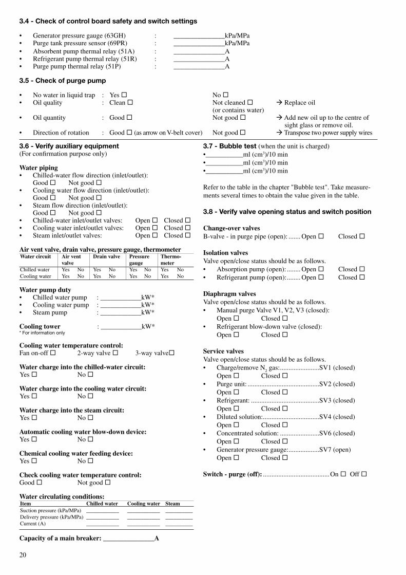
3.7 - Bubble test (when the unit is charged)•___________ml (cm3)/10 min•___________ml (cm3)/10 min•___________ml (cm3)/10 min
Refer to the table in the chapter "Bubble test". Take measure-ments several times to obtain the value given in the table.
3.8 - Verify valve opening status and switch position
Change-over valvesB-valve - in purge pipe (open): ....... Open ® Closed ®
Isolation valvesValve open/close status should be as follows.• Absorption pump (open): ........ Open ® Closed ®• Refrigerant pump (open): ........ Open ® Closed ®
Diaphragm valvesValve open/close status should be as follows.• Manual purge Valve V1, V2, V3 (closed): Open ® Closed ®• Refrigerant blow-down valve (closed): Open ® Closed ®
service valvesValve open/close status should be as follows.• Charge/remove N
2 gas: .......................SV1 (closed)
Open ® Closed ®• Purge unit: ..........................................SV2 (closed) Open ® Closed ®• Refrigerant: ........................................SV3 (closed) Open ® Closed ®• Diluted solution: .................................SV4 (closed) Open ® Closed ®• Concentrated solution: .......................SV6 (closed) Open ® Closed ®• Generator pressure gauge: ..................SV7 (open) Open ® Closed ®
switch - purge (off): .......................................On ® Off ®
3.6 - Verify auxiliary equipment(For confirmation purpose only)
Water piping• Chilled-water flow direction (inlet/outlet):
Good ® Not good ®• Cooling water flow direction (inlet/outlet):
Good ® Not good ®• Steam flow direction (inlet/outlet):
Good ® Not good ®• Chilled-water inlet/outlet valves: Open ® Closed ®• Cooling water inlet/outlet valves: Open ® Closed ®• Steam inlet/outlet valves: Open ® Closed ®
Air vent valve, drain valve, pressure gauge, thermometerWater circuit Air vent Drain valve Pressure Thermo- valve gauge meterChilled water Yes No Yes No Yes No Yes No Cooling water Yes No Yes No Yes No Yes No
Water pump duty• Chilled water pump : ____________kW* • Cooling water pump : ____________kW* • Steam pump : ____________kW*
Cooling tower : ____________kW* * For information only
Cooling water temperature control:Fan on-off ® 2-way valve ® 3-way valve®
Water charge into the chilled-water circuit:Yes ® No ®
Water charge into the cooling water circuit:Yes ® No ®
Water charge into the steam circuit:Yes ® No ®
Automatic cooling water blow-down device:Yes ® No ®
Chemical cooling water feeding device:Yes ® No ®
Check cooling water temperature control:Good ® Not good ®
Water circulating conditions:Item Chilled water Cooling water steam Suction pressure (kPa/MPa) ____________ ____________ __________Delivery pressure (kPa/MPa) ____________ ____________ __________Current (A) ____________ ____________ __________
Capacity of a main breaker: _______________A
3.4 - Check of control board safety and switch settings
• Generator pressure gauge (63GH) : _______________kPa/MPa• Purge tank pressure sensor (69PR) : _______________kPa/MPa• Absorbent pump thermal relay (51A) : _______________A• Refrigerant pump thermal relay (51R) : _______________A• Purge pump thermal relay (51P) : _______________A
3.5 - Check of purge pump
• No water in liquid trap : Yes ® No ®• Oil quality : Clean ® Not cleaned ® ‡ Replace oil (or contains water)• Oil quantity : Good ® Not good ® ‡ Add new oil up to the centre of sight glass or remove oil.• Direction of rotation : Good ® (as arrow on V-belt cover) Not good ® ‡ Transpose two power supply wires
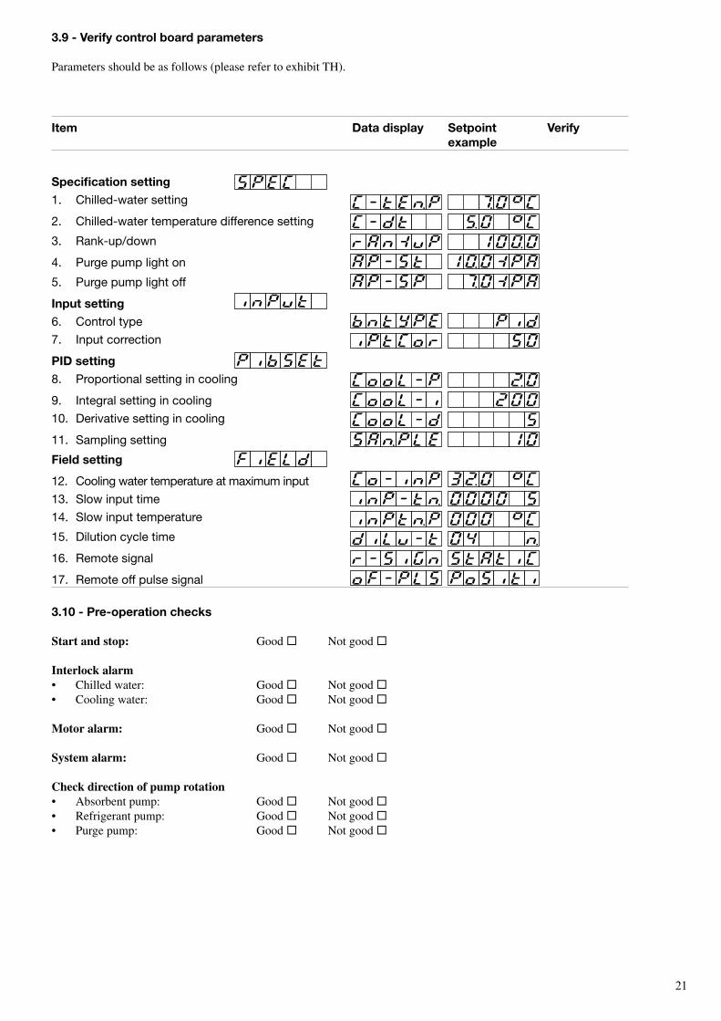
Item Data display setpoint Verify example
specification setting1. Chilled-water setting
2. Chilled-water temperature difference setting
3. rank-up/down
4. Purge pump light on
5. Purge pump light off
Input setting6. Control type
7. Input correction
PID setting8. Proportional setting in cooling
9. Integral setting in cooling
10. Derivative setting in cooling
11. Sampling setting
Field setting
12. Cooling water temperature at maximum input
13. Slow input time
14. Slow input temperature
15. Dilution cycle time
16. remote signal
17. remote off pulse signal
21
3.10 - Pre-operation checks
start and stop: Good ® Not good ®
Interlock alarm• Chilled water: Good ® Not good ®• Cooling water: Good ® Not good ®
Motor alarm: Good ® Not good ® system alarm: Good ® Not good ®
Check direction of pump rotation• Absorbent pump: Good ® Not good ®• Refrigerant pump: Good ® Not good ®• Purge pump: Good ® Not good ®
3.9 - Verify control board parameters
Parameters should be as follows (please refer to exhibit TH).
22
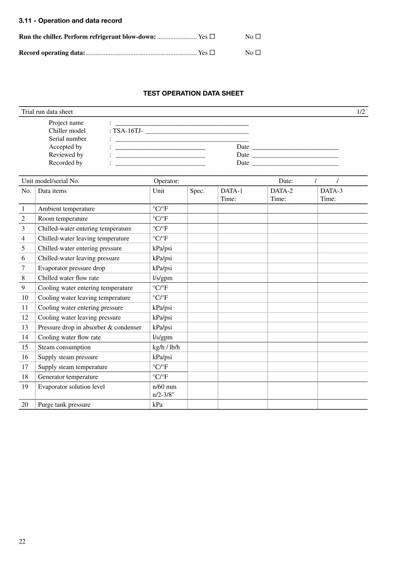
TesT oPerATIoN DATA sHeeT
Trial run data sheet 1/2
Project name : ________________________________________Chiller model : TSA-16TJ- _______________________________Serial number : ________________________________________Accepted by : ___________________________ Date __________________________Reviewed by : ___________________________ Date __________________________Recorded by : ___________________________ Date __________________________
Unit model/serial No. Operator: Date: / /
No. Data items Unit Spec. DATA-1Time:
DATA-2Time:
DATA-3Time:
1 Ambient temperature °C/°F
2 Room temperature °C/°F
3 Chilled-water entering temperature °C/°F
4 Chilled-water leaving temperature °C/°F
5 Chilled-water entering pressure kPa/psi
6 Chilled-water leaving pressure kPa/psi
7 Evaporator pressure drop kPa/psi
8 Chilled water flow rate l/s/gpm
9 Cooling water entering temperature °C/°F
10 Cooling water leaving temperature °C/°F
11 Cooling water entering pressure kPa/psi
12 Cooling water leaving pressure kPa/psi
13 Pressure drop in absorber & condenser kPa/psi
14 Cooling water flow rate l/s/gpm
15 Steam consumption kg/h / lb/h
16 Supply steam pressure kPa/psi
17 Supply steam temperature °C/°F
18 Generator temperature °C/°F
19 Evaporator solution level n/60 mmn/2-3/8"
20 Purge tank pressure kPa
3.11 - operation and data record
Run the chiller. Perform refrigerant blow-down: ........................ Yes ® No ®
Record operating data: ................................................................... Yes ® No ®
2�
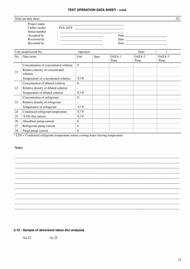
3.12 - sample of absorbent taken (for analysis)
Yes ® No ®
TesT oPerATIoN DATA sHeeT - cont.
Trial run data sheet 2/2
Project name : ________________________________________Chiller model : TSA-16TJ- _______________________________Serial number : ________________________________________Accepted by : ___________________________ Date __________________________Reviewed by : ___________________________ Date __________________________Recorded by : ___________________________ Date __________________________
Unit model/serial No. Operator: Date: / /
No. Data items Unit Spec. DATA-1Time:
DATA-2Time:
DATA-3Time:
21
Concentration of concentrated solution %
Relative density of concentrated solution
-
Temperature of concentrated solution °C/°F
22
Concentration of diluted solution %
Relative density of diluted solution -
Temperature of diluted solution °C/°F
23
Concentration of refrigerant %
Relative density of refrigerant -
Temperature of refrigerant °C/°F
24 Condensed refrigerant temperature °C/°F
25 *LTD (See below) °C/°F
26 Absorbent pump current A
27 Refrigerant pump current A
28 Purge pump current A
* LTD = Condensed refrigerant temperature minus cooling water leaving temperature
notes
_______________________________________________________________________________________________________
_______________________________________________________________________________________________________
_______________________________________________________________________________________________________
_______________________________________________________________________________________________________
_______________________________________________________________________________________________________
_______________________________________________________________________________________________________
_______________________________________________________________________________________________________
_______________________________________________________________________________________________________
_______________________________________________________________________________________________________
_______________________________________________________________________________________________________
_______________________________________________________________________________________________________
2�
4 - eXHIBITs
4.1 - exhibit TA
4.1.1 - Precautions for use
Installation and operationBefore installing and operating this chiller, read all applicable manual(s).
WARNING: Do not store or use gasoline, thinner or other flammable vapours, liquids and materials in the vicinity of the chiller.
Machine room• Keep the machine room temperature between 5°C and
40°C to protect against solution crystallisation during chiller shut-down.
• Keep the humidity in the machine room below 90%.• Leave the service and maintenance clearances shown in
the dimensional drawing.
PurgingEnsure that air cannot leak into the chiller (refer to the relevant manuals).
The chiller has a palladium cell as an auto-purge system; do not turn off the main power supply to the chiller during chiller shut-down.
Pumps and air handling unitsOperate the chilled-water pump(s) and air handling unit(s) during the dilution cycle of the chiller.
During the operation of the chilled water pump(s), never manually stop the cooling water pump(s).
Winter seasonIn winter, ensure that the chilled and cooling water in the pipes does not freeze during chiller shut-down. If the cooling water pump(s) operate to provide frost protection of the cooling water, operate the chilled-water pump(s) simultaneously.
service and maintenanceThe chiller should be checked periodically. Please contact the service agent.
4.1.2 - Precautions for installation
• Always make sure that the installation complies with local regulations.
• The chiller is designed for indoor installation.• Install the chiller on a floor that is suitable to carry the
weight.• Leave the service and maintenance clearances shown in
the dimensional drawing.• Do not install the unit in a dusty environment.• If necessary, install anti-vibration mountings.• Install the control panel so that it is not exposed to direct
sunshine to ensure that the display is legible.• Do not install the unit near an exhaust gas outlet or
ventilation port.• Use a shackle, when lifting the chiller with lifting cables.
Insert the shackle into the hole on the lower shell.• Ensure that the unit does not fall sideways.• Keep sufficient space for a smooth installation.• Avoid shocks and sudden movements.• For units shipped as separate parts, assembly and welding
must be done by a qualified technician. Please refer to the relevant manuals.
• The wiring connection must be done by a qualified technician.
• Use steel conduits for the wiring between the field power supply and the chiller control panel.
• Connect the operation signal wires from the chiller to the chilled water pump and cooling water pump. Each pump is automatically operated by the chiller signal.
• Connect the interlock wire of each pump to the chiller.• If a remote signal is used, do not install this in parallel
with the power line.• Always connect an earth wire, but do not connect it to gas
pipes or water pipes, etc.
2�
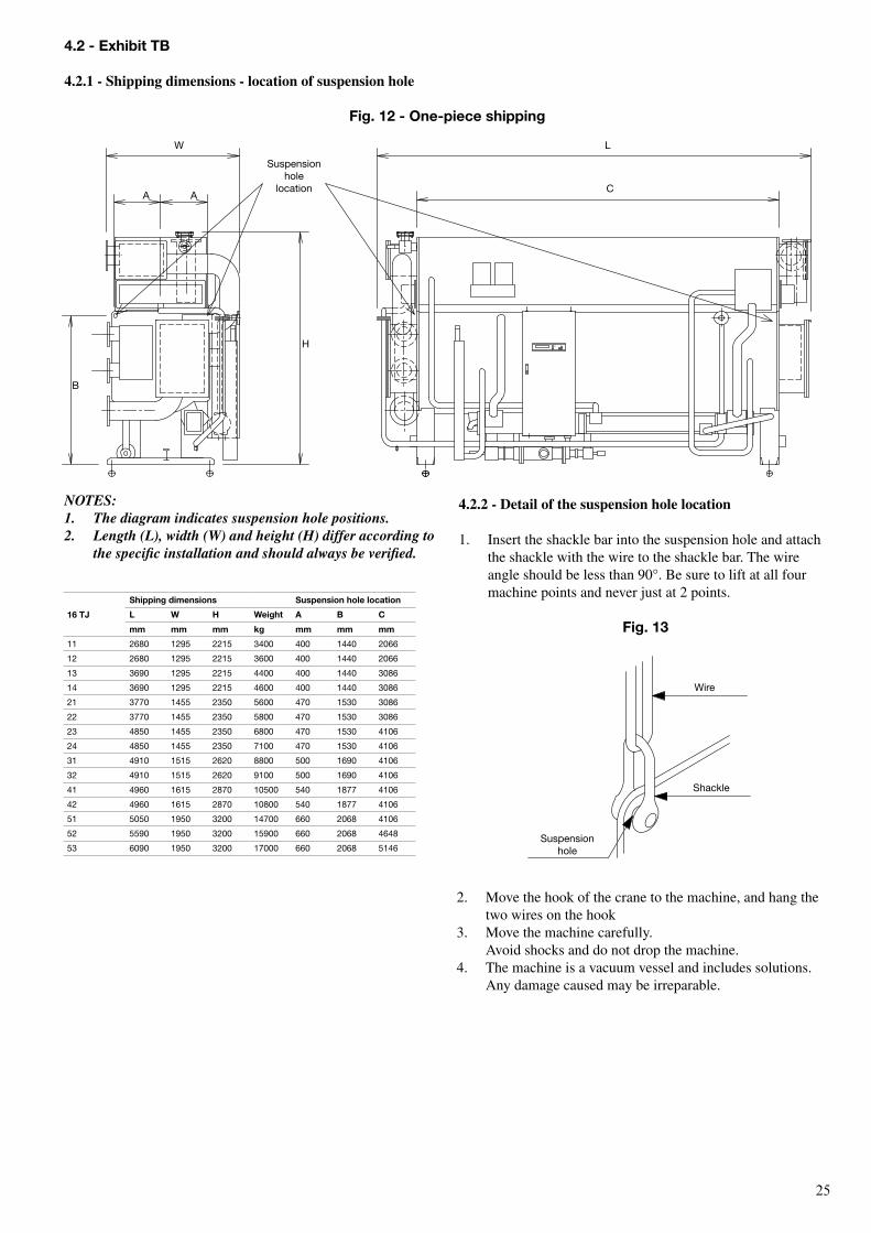
NOTES:1. The diagram indicates suspension hole positions.2. Length (L), width (W) and height (H) differ according to
the specific installation and should always be verified.
4.2.2 - Detail of the suspension hole location
1. Insert the shackle bar into the suspension hole and attach the shackle with the wire to the shackle bar. The wire angle should be less than 90°. Be sure to lift at all four machine points and never just at 2 points.
Fig. 13
2. Move the hook of the crane to the machine, and hang the two wires on the hook
3. Move the machine carefully. Avoid shocks and do not drop the machine.
4. The machine is a vacuum vessel and includes solutions. Any damage caused may be irreparable.
16 TJ
shipping dimensions suspension hole location
L W H Weight A B C
mm mm mm kg mm mm mm
11 2680 1295 2215 3400 400 1440 2066
12 2680 1295 2215 3600 400 1440 2066
13 3690 1295 2215 4400 400 1440 3086
14 3690 1295 2215 4600 400 1440 3086
21 3770 1455 2350 5600 470 1530 3086
22 3770 1455 2350 5800 470 1530 3086
23 4850 1455 2350 6800 470 1530 4106
24 4850 1455 2350 7100 470 1530 4106
31 4910 1515 2620 8800 500 1690 4106
32 4910 1515 2620 9100 500 1690 4106
41 4960 1615 2870 10500 540 1877 4106
42 4960 1615 2870 10800 540 1877 4106
51 5050 1950 3200 14700 660 2068 4106
52 5590 1950 3200 15900 660 2068 4648
53 6090 1950 3200 17000 660 2068 5146
4.2 - exhibit TB
4.2.1 - shipping dimensions - location of suspension hole
Fig. 12 - one-piece shipping
Wire
Shackle
Suspension hole
W L
CA A
b
H
Suspension hole
location
2�
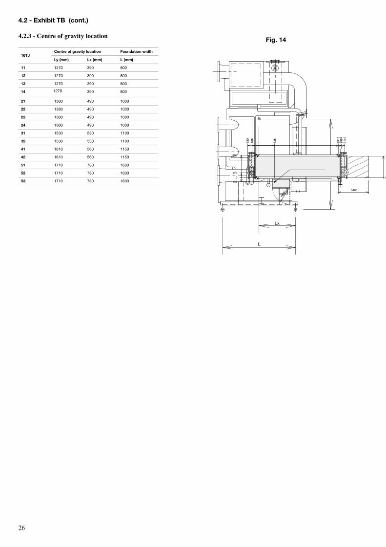
16TJCentre of gravity location Foundation width
Ly (mm) Lx (mm) L (mm)
11 1270 390 800
12 1270 390 800
13 1270 390 800
14 1270 390 800
21 1380 490 1000
22 1380 490 1000
23 1380 490 1000
24 1380 490 1000
31 1530 530 1100
32 1530 530 1100
41 1610 560 1150
42 1610 560 1150
51 1710 780 1600
52 1710 780 1600
53 1710 780 1600
Fig. 14
4.2 - exhibit TB (cont.)
4.2.3 - Centre of gravity location
L
Lx
Ly
330
185
170
635
R600
3146
780
2916
145
800
2987
0
0
0
3400
2�
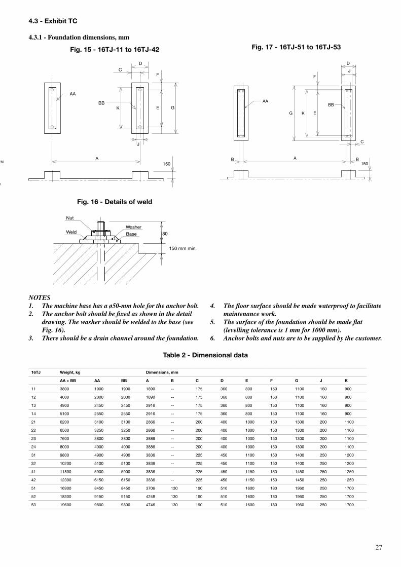
NOTES1. The machine base has a ø50-mm hole for the anchor bolt.2. The anchor bolt should be fixed as shown in the detail
drawing. The washer should be welded to the base (see Fig. 16).
3. There should be a drain channel around the foundation.
16TJ Weight, kg Dimensions, mm
AA + BB AA BB A B C D e F G J K
11 3800 1900 1900 1890 -- 175 360 800 150 1100 160 900
12 4000 2000 2000 1890 -- 175 360 800 150 1100 160 900
13 4900 2450 2450 2916 -- 175 360 800 150 1100 160 900
14 5100 2550 2550 2916 -- 175 360 800 150 1100 160 900
21 6200 3100 3100 2866 -- 200 400 1000 150 1300 200 1100
22 6500 3250 3250 2866 -- 200 400 1000 150 1300 200 1100
23 7600 3800 3800 3886 -- 200 400 1000 150 1300 200 1100
24 8000 4000 4000 3886 -- 200 400 1000 150 1300 200 1100
31 9800 4900 4900 3836 -- 225 450 1100 150 1400 250 1200
32 10200 5100 5100 3836 -- 225 450 1100 150 1400 250 1200
41 11800 5900 5900 3836 -- 225 450 1150 150 1450 250 1250
42 12300 6150 6150 3836 -- 225 450 1150 150 1450 250 1250
51 16900 8450 8450 3706 130 190 510 1600 180 1960 250 1700
52 18300 9150 9150 4248 130 190 510 1600 180 1960 250 1700
53 19600 9800 9800 4746 130 190 510 1600 180 1960 250 1700
Table 2 - Dimensional data
Fig. 15 - 16TJ-11 to 16TJ-42 Fig. 17 - 16TJ-51 to 16TJ-53
4. The floor surface should be made waterproof to facilitate maintenance work.
5. The surface of the foundation should be made flat (levelling tolerance is 1 mm for 1000 mm).
6. Anchor bolts and nuts are to be supplied by the customer.
Fig. 16 - Details of weld
4.3 - exhibit TC
4.3.1 - Foundation dimensions, mm
150A BB
D
C
E
F
G
J
K
AABB
150A
GE
FC
AA
BBK
D
J
Nut
WeldWasher
base 80
150 mm min.
330
185
170
635
R600
3146
780
2916
145
800
2987
0
0
0
3400
2�
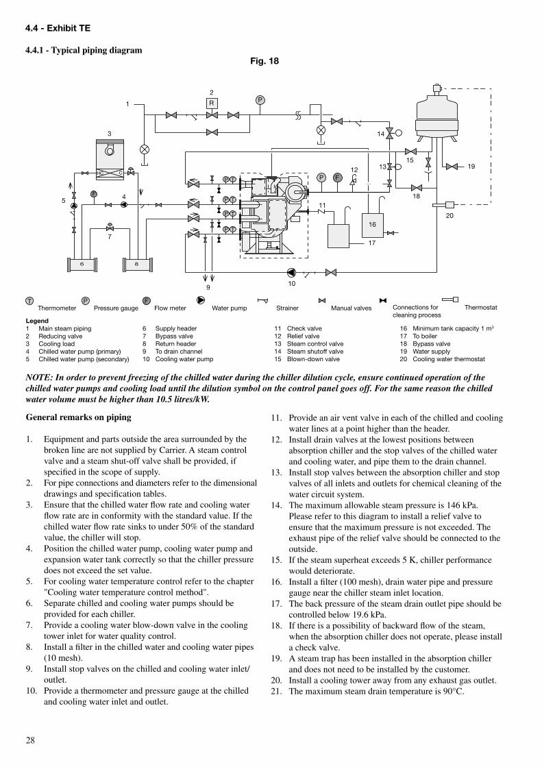
General remarks on piping
1. Equipment and parts outside the area surrounded by the broken line are not supplied by Carrier. A steam control valve and a steam shut-off valve shall be provided, if specified in the scope of supply.
2. For pipe connections and diameters refer to the dimensional drawings and specification tables.
3. Ensure that the chilled water flow rate and cooling water flow rate are in conformity with the standard value. If the chilled water flow rate sinks to under 50% of the standard value, the chiller will stop.
4. Position the chilled water pump, cooling water pump and expansion water tank correctly so that the chiller pressure does not exceed the set value.
5. For cooling water temperature control refer to the chapter "Cooling water temperature control method".
6. Separate chilled and cooling water pumps should be provided for each chiller.
7. Provide a cooling water blow-down valve in the cooling tower inlet for water quality control.
8. Install a filter in the chilled water and cooling water pipes (10 mesh).
9. Install stop valves on the chilled and cooling water inlet/outlet.
10. Provide a thermometer and pressure gauge at the chilled and cooling water inlet and outlet.
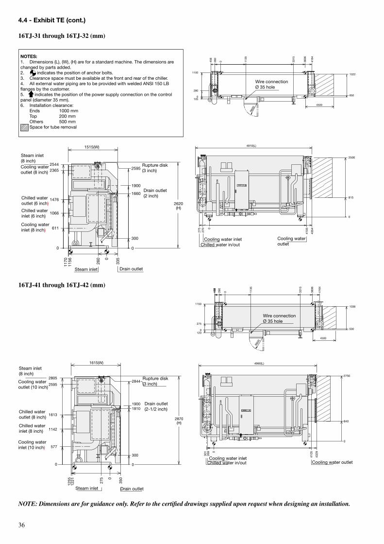
4.4 - exhibit Te
4.4.1 - Typical piping diagramFig. 18
NOTE: In order to prevent freezing of the chilled water during the chiller dilution cycle, ensure continued operation of the chilled water pumps and cooling load until the dilution symbol on the control panel goes off. For the same reason the chilled water volume must be higher than 10.5 litres/kW.
11. Provide an air vent valve in each of the chilled and cooling water lines at a point higher than the header.
12. Install drain valves at the lowest positions between absorption chiller and the stop valves of the chilled water and cooling water, and pipe them to the drain channel.
13. Install stop valves between the absorption chiller and stop valves of all inlets and outlets for chemical cleaning of the water circuit system.
14. The maximum allowable steam pressure is 146 kPa. Please refer to this diagram to install a relief valve to ensure that the maximum pressure is not exceeded. The exhaust pipe of the relief valve should be connected to the outside.
15. If the steam superheat exceeds 5 K, chiller performance would deteriorate.
16. Install a filter (100 mesh), drain water pipe and pressure gauge near the chiller steam inlet location.
17. The back pressure of the steam drain outlet pipe should be controlled below 19.6 kPa.
18. If there is a possibility of backward flow of the steam, when the absorption chiller does not operate, please install a check valve.
19. A steam trap has been installed in the absorption chiller and does not need to be installed by the customer.
20. Install a cooling tower away from any exhaust gas outlet.21. The maximum steam drain temperature is 90°C.
Legend1 Main steam piping2 reducing valve3 Cooling load4 Chilled water pump (primary)5 Chilled water pump (secondary)
6 Supply header7 bypass valve8 return header9 to drain channel10 Cooling water pump
16 Minimum tank capacity 1 m3
17 to boiler18 bypass valve19 Water supply20 Cooling water thermostat
11 Check valve12 relief valve13 Steam control valve14 Steam shutoff valve15 blown-down valve
HC C
F
R
T
16
P
TP
TP
TP
P
P F
T P F
7
6 8
3
45
13
17
10
20
1912
15
18
9
2
1
11
14
thermometer Pressure gauge Flow meter Water pump Strainer Manual valves thermostatConnections for cleaning process
2�
4.4 - exhibit Te (cont.)
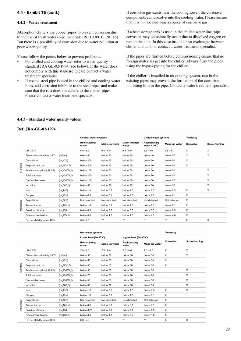
4.4.2 - Water treatment
Absorption chillers use copper pipes to prevent corrosion due to the use of fresh water (pipe material: JIS H 3300 C1201TS)But there is a possibility of corrosion due to water pollution or poor water quality.
Please follow the points below to prevent problems:• For chilled and cooling water refer to water quality
standard JRA GL-02-1994 (see below). If the water does not comply with this standard, please contact a water treatment specialist.
• If coated steel pipe is used in the chilled and cooling water lines, add corrosion inhibitor to the steel pipes and make sure that the rust does not adhere to the copper pipes. Please contact a water treatment specialist.
If corrosive gas exists near the cooling tower, the corrosive components can dissolve into the cooling water. Please ensure that it is not located near a source of corrosive gas.
If a heat storage tank is used in the chilled water line, pipe corrosion may occasionally occur due to dissolved oxygen or rust in the tank. In this case install a heat exchanger between chiller and tank, or contact a water treatment specialist.
If the pipes are flushed before commissioning ensure that no foreign materials get into the chiller. Always flush the pipes using the bypass piping for the chiller.
If the chiller is installed in an existing system, rust in the existing pipes may prevent the formation of the corrosion-inhibiting film in the pipe. Contact a water treatment specialist.
Cooling water systems Chilled water systems Tendency
recirculating water
Make-up wateronce-through water
recirculating water < 20°C
Make-up water Corrosive scale-forming
Sta
ndar
d
pH (25°C) 6.5 - 8.2 6.0 - 8.0 6.8 - 8.0 6.8 - 8.0 6.8 - 8.0 X X
Electrical conductivity 25°C (mS/m) below 80 below 30 below 40 below 40 below 30 X X
Chroride ion (mgCl-/l) below 200 below 50 below 50 below 50 below 50 X
Sulphuric acid ion (mgSo42-/l) below 200 below 50 below 50 below 50 below 50 X
Acid consumption (pH 4.8) (mgCaCo3/l) below 100 below 50 below 50 below 50 below 50 X
total hardness (mgCaCo3/l) below 200 below 70 below 70 below 70 below 70 X
Calcium hardness (mgCaCo3/l) below 150 below 50 below 50 below 50 below 50 X
Ion silica (mgSio2/l) below 50 below 30 below 30 below 30 below 30 X
ref
eren
ce
Iron (mgFe/l) below 1.0 below 0.3 below 1.0 below 1.0 below 0.3 X X
Copper (mgCu/l) below 0.3 below 0.1 below 1.0 below 1.0 below 0.1 X
Sulphide ion (mgS2-/l) Not detected Not detected Not detected Not detected Not detected X
Ammonium ion (mgNH4+/l) below 1.0 below 0.1 below 1.0 below 1.0 below 0.1 X
residual chlorine (mgCl/l) below 0.3 below 0.3 below 0.3 below 0.3 below 0.3 X
Free carbon dioxide (mgCo2/l) below 4.0 below 4.0 below 4.0 below 4.0 below 4.0 X
ryzner stability index (rSI) 6.0 - 7.0 *** *** *** *** X X
Hot-water systems Tendency
Lower level (20-60°C) Higher level (60-90°C)
Corrosive scale-formingrecirculating water
Make-up waterrecirculating water
Make-up water
Sta
ndar
d
pH (25°C) 7.0 - 8.0 7.0 - 8.0 7.0 - 8.0 7.0 - 8.0 X X
Electrical conductivity 25°C (mS/m) below 30 below 30 below 30 below 30 X X
Chroride ion (mgCl-/l) below 50 below 50 below 30 below 30 X
Sulphuric acid ion (mgSo42-/l) below 50 below 50 below 30 below 30 X
Acid consumption (pH 4.8) (mgCaCo3/l) below 50 below 50 below 50 below 50 X
total hardness (mgCaCo3/l) below 70 below 70 below 70 below 70 X
Calcium hardness (mgCaCo3/l) below 50 below 50 below 50 below 50 X
Ion silica (mgSio2/l) below 30 below 30 below 30 below 30 X
ref
eren
ce
Iron (mgFe/l) below 1.0 below 0.3 below 1.0 below 0.3 X X
Copper (mgCu/l) below 1.0 below 0.1 below 1.0 below 0.1 X
Sulphide ion (mgS2-/l) Not detected Not detected Not detected Not detected X
Ammonium ion (mgNH4+/l) below 0.3 below 0.1 below 0.1 below 0.1 X
residual chlorine (mgCl/l) below 0.25 below 0.3 below 0.1 below 0.3 X
Free carbon dioxide (mgCo2/l) below 0.4 below 4.0 below 0.4 below 1.0 X
ryzner stability index (rSI) 6.0 - 7.0 *** *** *** X X
4.4.3 - standard water quality values
Ref: JRA-GL-02-1994
�0
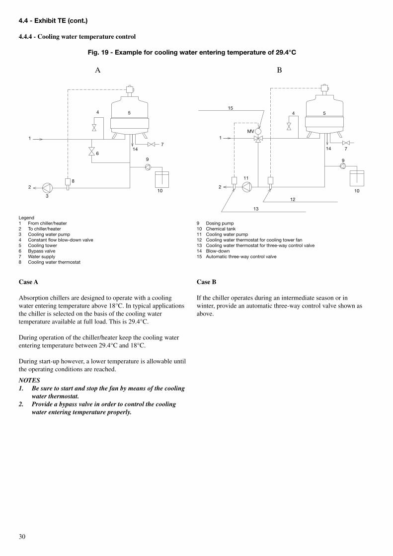
Case A
Absorption chillers are designed to operate with a cooling water entering temperature above 18°C. In typical applications the chiller is selected on the basis of the cooling water temperature available at full load. This is 29.4°C.
During operation of the chiller/heater keep the cooling water entering temperature between 29.4°C and 18°C.
During start-up however, a lower temperature is allowable until the operating conditions are reached.
NOTES1. Be sure to start and stop the fan by means of the cooling
water thermostat.2. Provide a bypass valve in order to control the cooling
water entering temperature properly.
Legend1 From chiller/heater2 to chiller/heater3 Cooling water pump4 Constant flow blow-down valve5 Cooling tower6 bypass valve7 Water supply8 Cooling water thermostat
Case B
If the chiller operates during an intermediate season or in winter, provide an automatic three-way control valve shown as above.
4.4 - exhibit Te (cont.)
4.4.4 - Cooling water temperature control
Fig. 19 - example for cooling water entering temperature of 29.4°C
10
9
147
54
6
1
2
3
811
13
12
10
9
14 7
54
1
2
15
MV
A B
9 Dosing pump10 Chemical tank11 Cooling water pump12 Cooling water thermostat for cooling tower fan13 Cooling water thermostat for three-way control valve14 blow-down15 Automatic three-way control valve
�1
M = E + W + BW + B
E + W + BN =
N - 11
B = x E - WN - 1N
M = x E
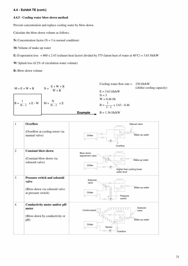
1 overflow
(Overflow at cooling tower via manual valve)
2 Constant blow-down
(Constant blow-down via solenoid valve)
3 Pressure switch and solenoid valve
(Blow-down via solenoid valve at pressure switch)
4 Conductivity meter and/or pH meter
(Blow-down by conductivity or pH)
4.4 - exhibit Te (cont.)
4.4.5 - Cooling water blow-down method
Prevent concentration and replace cooling water by blow-down.
Calculate the blow-down volume as follows.
n: Concentration factor (N = 3 is normal condition)
M: Volume of make-up water
e: Evaporation loss = 860 x 2.43 (exhaust heat factor) divided by 575 (latent heat of water at 40°C) = 3.63 l/h/kW
W: Splash loss (0.2% of circulation water volume)
B: Blow-down volume
P
P
P
P
Chiller
Manual valve
Make-up water
overflow
Make-up water
blow-down adjustment valve
Chiller
Chiller
Chiller
Higher than cooling tower water level
Make-up water
Make-up water
Solenoid valve
Solenoid valve
overflow
Sensor
Control panel
Pressure switch
Cooling water flow rate = 230 l/h/kW (chiller cooling capacity)E = 3.63 l/h/kWN = 3W = 0.46 l/h
B =
B = 1.36 l/h/kW
3 - 1
1x 3.63 - 0.46
example
�2
4.4 - exhibit Te (cont.)
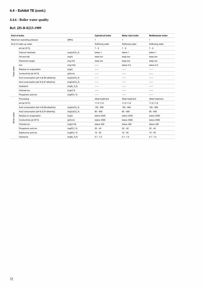
4.4.6 - Boiler water quality
Ref: JIs-B-8223-1989
Kind of boiler Cylindrical boiler Water tube boiler Multibubular boiler
Maximum operating pressure (MPa) 1 1 1
Kind of make-up water Softening water Softening water Softening water
Feed
wat
er
pH (at 25°C) 7 - 9 7 - 9 7 - 9
Calcium hardness (mgCaCo3 /l) below 1 below 1 below 1
Fat and oils (mg/l) keep low keep low keep low
Dissolved oxygen (mg o/l) keep low keep low keep low
Iron (mg Fe/l) ----- below 0.3 below 0.3
residue on evaporation (mg/l) ----- ----- -----
Conductivity (at 25°C) (µS/cm) ----- ----- -----
Acid consumption (pH 4.8) (M-alkalinity) (mgCaCo3 /l) ----- ----- -----
Acid consumption (pH 8.3) (P-alkalinity) (mgCaCo3 /l) ----- ----- -----
Hydrazine (mgN2 H4/l) ----- ----- -----
Chloride ion (mgCl-/l) ----- ----- -----
Phosphoric acid ion (mgPo43-/l) ----- ----- -----
boi
ler
wat
er
Processing Alkali treatment Alkali treatment Alkali treatment
pH (at 25°C) 11.0-11.8 11.0-11.8 11.0-11.8
Acid consumption (pH 4.8) (M-alkalinity) (mgCaCo3 /l) 100 - 800 100 - 800 100 - 800
Acid consumption (pH 8.3) (P-alkalinity) (mgCaCo3 /l) 80 - 600 80 - 600 80 - 600
residue on evaporation (mg/l) below 2500 below 2500 below 2500
Conductivity (at 25°C) (µS/cm) below 4000 below 4000 below 4000
Chloride ion (mgCl-/lit) below 400 below 400 below 400
Phosphoric acid ion (mgPo43-/l) 20 - 40 20 - 40 20 - 40
Sulphurous acid ion (mgSo32-/l) 10 - 50 10 - 50 10 - 50
Hydrazine (mgN2 H4/l) 0.1- 1.0 0.1- 1.0 0.1- 1.0
��
Fig. 21
Fig. 22
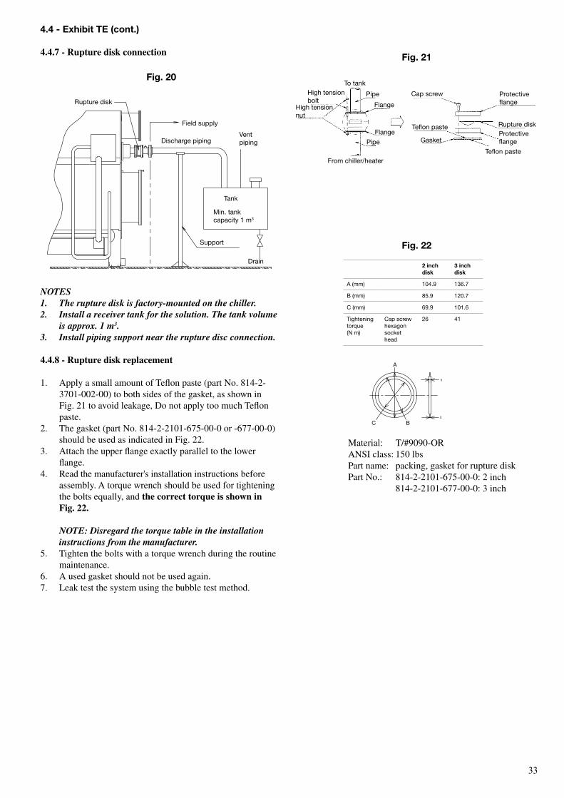
Material: T/#9090-ORANSI class: 150 lbsPart name: packing, gasket for rupture diskPart No.: 814-2-2101-675-00-0: 2 inch 814-2-2101-677-00-0: 3 inch
2 inch disk
3 inch disk
A (mm) 104.9 136.7
b (mm) 85.9 120.7
C (mm) 69.9 101.6
tightening torque (N m)
Cap screw hexagon socket head
26 41
to tankHigh tension bolt
High tension nut
Pipe
Flange
Flange
Pipe
From chiller/heater
Cap screw
teflon paste
Gasket
Protective flange
rupture diskProtective flange
teflon paste
4.4 - exhibit Te (cont.)
4.4.7 - Rupture disk connection
Fig. 20
rupture disk
Discharge pipingVent piping
tank
Min. tank capacity 1 m3
Support
Drain
Field supply
NOTES1. The rupture disk is factory-mounted on the chiller.2. Install a receiver tank for the solution. The tank volume
is approx. 1 m3.3. Install piping support near the rupture disc connection.
4.4.8 - Rupture disk replacement
1. Apply a small amount of Teflon paste (part No. 814-2-3701-002-00) to both sides of the gasket, as shown in Fig. 21 to avoid leakage, Do not apply too much Teflon paste.
2. The gasket (part No. 814-2-2101-675-00-0 or -677-00-0) should be used as indicated in Fig. 22.
3. Attach the upper flange exactly parallel to the lower flange.
4. Read the manufacturer's installation instructions before assembly. A torque wrench should be used for tightening the bolts equally, and the correct torque is shown in Fig. 22.
NOTE: Disregard the torque table in the installation
instructions from the manufacturer.5. Tighten the bolts with a torque wrench during the routine
maintenance.6. A used gasket should not be used again.7. Leak test the system using the bubble test method.
5
3
C b
A
��
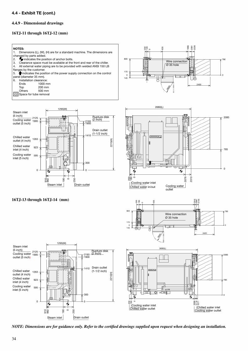
16TJ-13 through 16TJ-14 (mm)
NOTE: Dimensions are for guidance only. Refer to the certified drawings supplied upon request when designing an installation.
4.4 - exhibit Te (cont.)
4.4.9 - Dimensional drawings
16TJ-11 through 16TJ-12 (mm)
170
2226
R600
2081
1896
635
230
129
0
780
2400
145
800
00
Wire connection Ø 35 hole
19002193
2215
(H)
2125
300
1295(W)
910
882
190
250
1995
1263
923
595
1410
0
0
0
Steam inlet (5 inch)Cooling water outlet (5 inch)
Chilled water outlet (4 inch)
Chilled water inlet (4 inch)
Cooling water inlet (5 inch)
rupture disk (2 inch)
Steam inlet Drain outlet
Drain outlet (1-1/2 inch)
2680(L)
200
180
2310
2076
2085
785
0
0
Cooling water inletChilled water in/out Cooling water
outlet
330
185
170
635
R600
3146
780
2916
145
800
2987
0
0
0
3400
Wire connection Ø 35 hole
19002193
2215
(H)
300
910
882
250
1410
190
21251995
1263
923
595
1295(W)
0
0
0
Steam inlet (5 inch)Cooling water outlet (5 inch)
Chilled water outlet (4 inch)Chilled water inlet (4 inch)
Cooling water inlet (5 inch)
rupture disk (2 inch)
Steam inlet Drain outlet
Drain outlet (1-1/2 inch)
3096180
3690(L)
2085
785
3271
3116200 0
0
Chilled water inletCooling water outlet
Cooling water inletChilled water outlet
NoTes:1. Dimensions (L), (W), (H) are for a standard machine. the dimensions are changed by parts added.2. indicates the position of anchor bolts.3. Clearance space must be available at the front and rear of the chiller.4. All external water piping are to be provided with welded ANSI 150 Lb flanges by the customer.5. indicates the position of the power supply connection on the control panel (diameter 35 mm).6. Installation clearance: Ends 1000 mm top 200 mm others 500 mm Space for tube removal
��
3141
2962
2866
710
355
210
0
270
R600
220
9261000
1250
3400
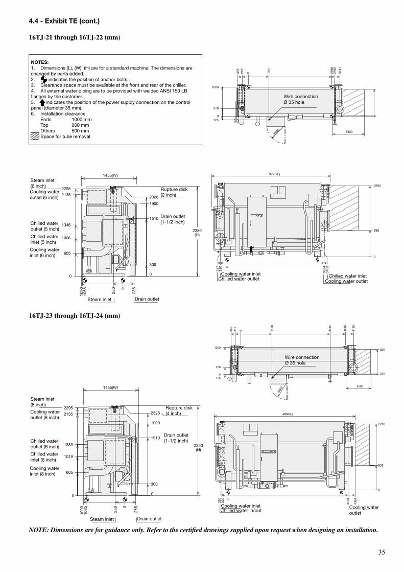
NoTes:1. Dimensions (L), (W), (H) are for a standard machine. the dimensions are changed by parts added.2. indicates the position of anchor bolts.3. Clearance space must be available at the front and rear of the chiller.4. All external water piping are to be provided with welded ANSI 150 Lb flanges by the customer.5. indicates the position of the power supply connection on the control panel (diameter 35 mm).6. Installation clearance: Ends 1000 mm top 200 mm others 500 mm Space for tube removal
16TJ-23 through 16TJ-24 (mm)
NOTE: Dimensions are for guidance only. Refer to the certified drawings supplied upon request when designing an installation.
Wire connection Ø 35 hole
4189
3886
3312
1160
355
210
0
270
R600
220
9261000
1250
4500
Wire connection Ø 35 hole
4.4 - exhibit Te (cont.)
16TJ-21 through 16TJ-22 (mm)
2350(H)
1900
2328
300
1510
1455(W)
285
1090 25
0
2295
2135
1346
1006
605
0
1065 0
0
Steam inlet (6 inch)Cooling water outlet (6 inch)
Chilled water outlet (5 inch)
Chilled water inlet (5 inch)
Cooling water inlet (6 inch)
rupture disk (2 inch)
Drain outletSteam inlet
Drain outlet (1-1/2 inch)
220
3770(L)
2255
835
0
3084
310323
7 0
Chilled water outletCooling water inlet Chilled water inlet
Cooling water outlet
2350(H)
1900
2328
300
2295
1090 28
5
1510
1455(W)
2135
1333
1019
605
250
1065
0
0
0
Steam inlet (8 inch)
Cooling water outlet (8 inch)
Chilled water outlet (6 inch)
Chilled water inlet (6 inch)
Cooling water inlet (8 inch)
rupture disk (4 inch)
Drain outlet (1-1/2 inch)
Drain outletSteam inlet
4354
4104
2255
835
220
4850(L)
0
250 0
Chilled water in/outCooling water inlet Cooling water
outlet
��
3836
468
468
260
4164
3315
1135
0
275
R600
120
1150
0
1036
500
4500
Wire connection Ø 35 hole
NoTes:1. Dimensions (L), (W), (H) are for a standard machine. the dimensions are changed by parts added.2. indicates the position of anchor bolts.3. Clearance space must be available at the front and rear of the chiller.4. All external water piping are to be provided with welded ANSI 150 Lb flanges by the customer.5. indicates the position of the power supply connection on the control panel (diameter 35 mm).6. Installation clearance: Ends 1000 mm top 200 mm others 500 mm Space for tube removal
16TJ-41 through 16TJ-42 (mm)
NOTE: Dimensions are for guidance only. Refer to the certified drawings supplied upon request when designing an installation.
4164
3836
260
1135
458
3315
280
1022
R60
0
650105
1100
0
0
4500
Wire connection Ø 35 hole
410527
0
4354
4910(L)
2500
815
0
275
0
Cooling water inletChilled water in/out
Cooling water outlet
4329
4105301
269
4960(L)
2750
840
0
0
Chilled water in/outCooling water inlet
Cooling water outlet
4.4 - exhibit Te (cont.)
16TJ-31 through 16TJ-32 (mm)
2620(H)
1900
2595
300
2544
335
1660
1515(W)
2365
1476
1066
611
1156 26
0
1170
0 0
0
Steam inlet (8 inch)Cooling water outlet (8 inch)
Chilled water outlet (6 inch)
Chilled water inlet (6 inch)
Cooling water inlet (8 inch)
rupture disk (3 inch)
Drain outlet (2 inch)
Drain outletSteam inlet
1900
2870(H)
2844
1810
300
2805
1615(W)
350
1221 27
5
2595
1613
1142
577
1255
0 0
0
Cooling water outlet (10 inch)
Chilled water outlet (8 inch)
Chilled water inlet (8 inch)
Cooling water inlet (10 inch)
rupture disk (3 inch)
Steam inlet (8 inch)
Drain outletSteam inlet
Drain outlet (2-1/2 inch)
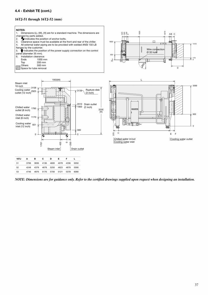
��
NoTes:1. Dimensions (L), (W), (H) are for a standard machine. the dimensions are changed by parts added.2. indicates the position of anchor bolts.3. Clearance space must be available at the front and rear of the chiller.4. All external water piping are to be provided with welded ANSI 150 Lb flanges by the customer.5. indicates the position of the power supply connection on the control panel (diameter 35 mm).6. Installation clearance: Ends 1000 mm top 200 mm others 500 mm Space for tube removal
NOTE: Dimensions are for guidance only. Refer to the certified drawings supplied upon request when designing an installation.
AB C
450
523
R600
1410
130
325
1020
173
3272
1600
20
0
0 0
D
Wire connection Ø 35 hole
16TJ A B C D e F L
51 3706 3836 4136 4600 4078 4336 5050
52 4248 4378 4678 5250 4623 4878 5590
53 4746 4876 5176 5700 5121 5378 6090
4.4 - exhibit Te (cont.)
16TJ-51 through 16TJ-52 (mm)
19003200(H)
1950(W)
3139
300
250
435
2010
1701
2925
1760
1170
651
0 0
0
3158
Steam inlet 10 inch
Cooling water outlet (12 inch)
Chilled water outlet (8 inch)
Chilled water inlet (8 inch)
Cooling water inlet (12 inch)
rupture disk (3 inch)
Drain outlet (2 inch)
Drain outletSteam inlet
3099
L
FE
900 3
70 0
0
Cooling water outletChilled water in/outCooling water inlet
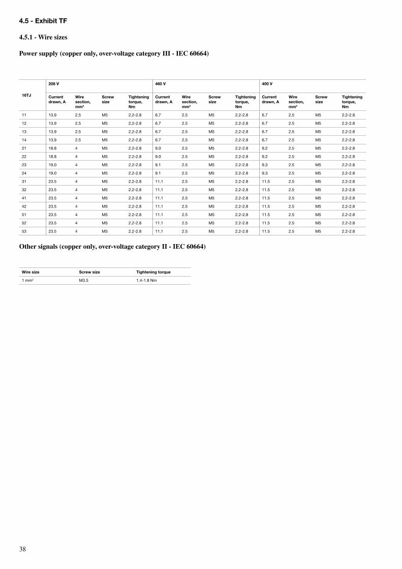
��
4.5 - exhibit TF
4.5.1 - Wire sizes
Power supply (copper only, over-voltage category III - IeC 60664)
16TJ
208 V 460 V 400 V
Current drawn, A
Wire section, mm2
screw size
Tightening torque, Nm
Current drawn, A
Wire section, mm2
screw size
Tightening torque, Nm
Current drawn, A
Wire section, mm2
screw size
Tightening torque, Nm
11 13.9 2.5 M5 2.2-2.8 6.7 2.5 M5 2.2-2.8 6.7 2.5 M5 2.2-2.8
12 13.9 2.5 M5 2.2-2.8 6.7 2.5 M5 2.2-2.8 6.7 2.5 M5 2.2-2.8
13 13.9 2.5 M5 2.2-2.8 6.7 2.5 M5 2.2-2.8 6.7 2.5 M5 2.2-2.8
14 13.9 2.5 M5 2.2-2.8 6.7 2.5 M5 2.2-2.8 6.7 2.5 M5 2.2-2.8
21 18.8 4 M5 2.2-2.8 9.0 2.5 M5 2.2-2.8 9.2 2.5 M5 2.2-2.8
22 18.8 4 M5 2.2-2.8 9.0 2.5 M5 2.2-2.8 9.2 2.5 M5 2.2-2.8
23 19.0 4 M5 2.2-2.8 9.1 2.5 M5 2.2-2.8 9.3 2.5 M5 2.2-2.8
24 19.0 4 M5 2.2-2.8 9.1 2.5 M5 2.2-2.8 9.3 2.5 M5 2.2-2.8
31 23.5 4 M5 2.2-2.8 11.1 2.5 M5 2.2-2.8 11.5 2.5 M5 2.2-2.8
32 23.5 4 M5 2.2-2.8 11.1 2.5 M5 2.2-2.8 11.5 2.5 M5 2.2-2.8
41 23.5 4 M5 2.2-2.8 11.1 2.5 M5 2.2-2.8 11.5 2.5 M5 2.2-2.8
42 23.5 4 M5 2.2-2.8 11.1 2.5 M5 2.2-2.8 11.5 2.5 M5 2.2-2.8
51 23.5 4 M5 2.2-2.8 11.1 2.5 M5 2.2-2.8 11.5 2.5 M5 2.2-2.8
52 23.5 4 M5 2.2-2.8 11.1 2.5 M5 2.2-2.8 11.5 2.5 M5 2.2-2.8
53 23.5 4 M5 2.2-2.8 11.1 2.5 M5 2.2-2.8 11.5 2.5 M5 2.2-2.8
other signals (copper only, over-voltage category II - IeC 60664)
Wire size screw size Tightening torque
1 mm2 M3.5 1.4-1.8 Nm
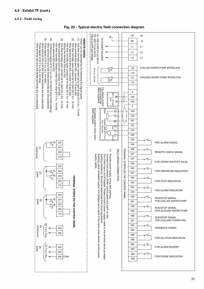
��
358
359
362
363
383
382
357
356323
323
323
HC 25
OC 25
120
170
350
335
334
UL
L3
L2
L1
G
CE
1 Y41 Y4
2 Y41 Y 4
2 Y4
COM
325
326
324
326
324
324
326
325
170
170
326
325
324
170
326
351
353
352
337
336
369
368
348
347
355
354
361
360
121
170
324
L3
L2
L1
PE
E
345
346
E
344
343
384
385
+
-
342
340
341
OA32
1Y
GT
4.5 - exhibit TF (cont.)
4.5.2 - Field wiring
Fig. 23 - Typical electric field connection diagram
For ALArM bUZZEr
For PUrGE INDICAtIoN
For DILUtIoN INDICAtIoN
FEEDbACK SIGNAL
rUN/StoP SIGNAL For CooLING toWEr FAN
rUN/StoP SIGNAL For CooLING WAtEr PUMP
rUN/StoP SIGNAL For CHILLED WAtEr PUMP
For ALArM INDICAtIoN
For StoP INDICAtIoN
For oPErAtIoN INDICAtIoN
rEMotE CHECK SIGNAL
PrE-ALArM SIGNAL
CooLING WAtEr PUMP INtErLoCK
CHILLED WAtEr PUMP INtErLoCK
tEr
MIN
AL S
trIP
S o
N tH
E C
oN
tro
L PAN
EL
to P
oW
Er
So
Ur
CE
DC
4 - 20 mA
CV
P
24 V d.c. 10 m
AFor steam
control valve motor
(field-sup
piied
)
UL: 208 V
/460 V-3 ph-60 H
z C
E: 400 V-3 p
h-50 Hz
FIELD
-SU
PP
LIED
PAN
EL
Te
rM
INA
L sT
rIP
s o
N T
He
Co
NT
ro
L PAN
eL
(1) continuous
(2) p
ulse(3) p
ulse(4) continuous
(5) p
ulse
FIELD
WIr
ING
Co
NN
EC
tIoN
(1) P
rovide p
ower sup
ply w
iring and earthing
C
onnect wire b
etween chiller control p
anel and earth on site.
the chiller has a circuit b
reaker. Please connect p
ower sup
ply cab
le to the terminal b
lock provid
ed.
E
arthing resistance: Should
be d
etermined
from local regulations
E
arthing cable: annealed
copp
er wire (p
lease use a cable of the sam
e cross section as the pow
er
supp
ly cable).
re
Mo
Te
sIG
NA
LC
hiller can be op
erated b
y the following five signal typ
es. (1)
Volt-free normally op
en contact (a) for start & stop
(24 V d
.c. 10 mA
):
Wire term
inal 324 and 323, connect 170 and
326. (2)
Volt-free normally op
en contact (a) for start (24 V d
.c. 10 mA
):
Wire term
inal 324 and 325, connect 170 and
326.
Volt-free normally op
en contact (a) for stop (24 V
d.c. 10 m
A):
W
iring the terminal 325 and
323. (3)
Volt-free normally op
en contact (a) for start (24 V d
.c. 10 mA
):
Wire term
inal 324 and 325, connect 170 and
326.
Volt-free normally closed
contact (b) for stop
(24 V d
.c. 10 mA
):
Wire term
inal 325 and 323.
(4) C
ontinuous signal of 24 V a.c./d
.c. for start & stop
(initial setting):
Wire term
inal 324 and 326 (these term
inals are non-polarized
) (5)
Pulse signal of 24 V
a.c./d.c. for start:
W
ire terminal 324 and
326 (these terminals are non-p
olarized)
P
ulse signal of 24 V a.c./d
.c. for stop:
W
ire terminal 325 and
326 (these terminals are non-p
olarized)
24 V a.c./d
.c.24 V
a.c./d.c.
For StEAM SHUtoFF VALVE
op
en C
losed C
MS
(24 V a.c.)
Pot: 135 o
hmFor steam
control valve p
ositioner (field
-supp
iied)
op
enC
losed
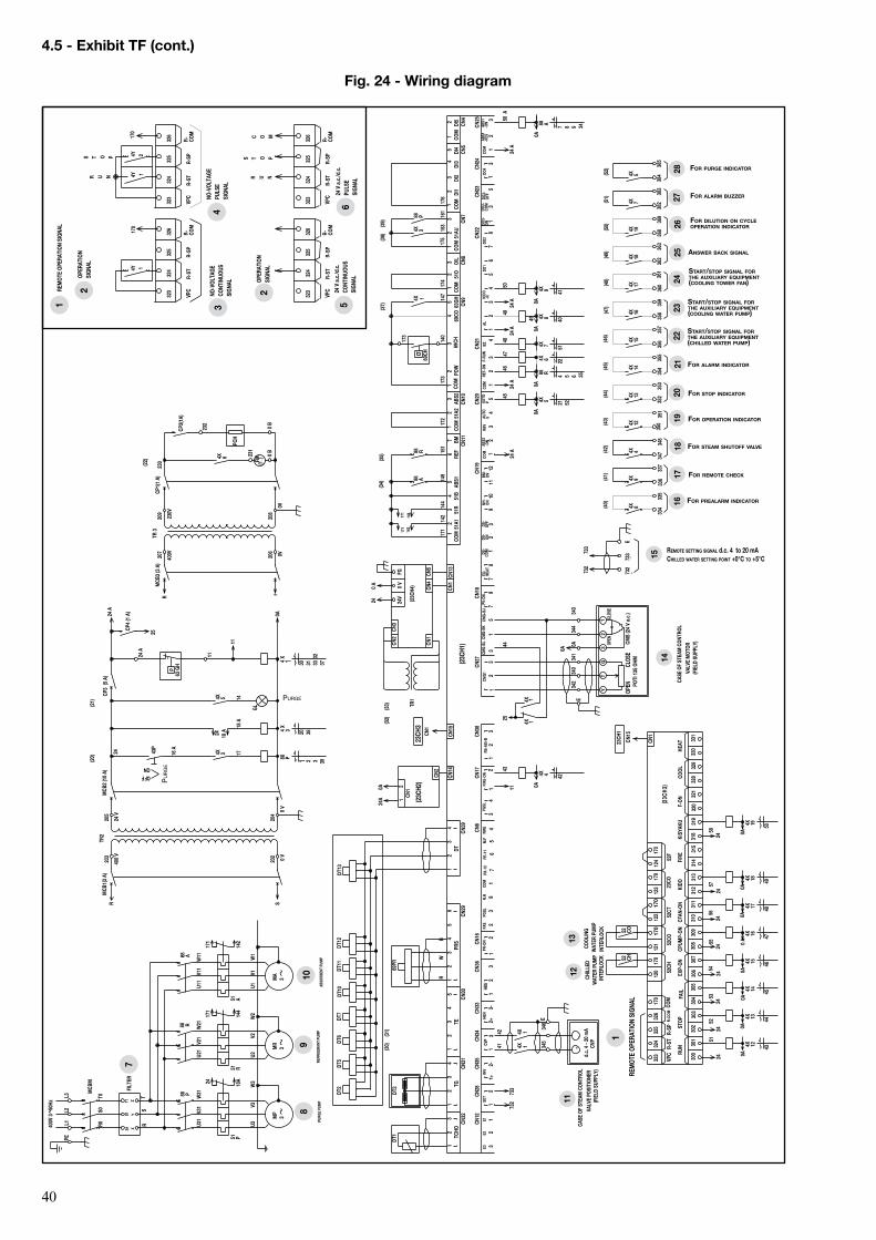
�0
4.5 - exhibit TF (cont.)
Fig. 24 - Wiring diagram
88
P MCB
M
U31
V3
1
W31
U1
V1
W1
88
R
144
14
9 15
1
4 5 6 35
140
DT1
69PR
24 A
RS-4
85-B
2
3
2 FI
RE-O
N
2 FI
RE
8 PR
-10
3 PR
-11
7
6
5 CO
M
M.F
PA
S PG
SL
N.H
PGSL
3
4
2
PR-O
N
5
7
PV-O
N CM
G-BJ
CM
G-BL
9 3
CMG-
BK
CMG1
2
3
ABS1
RE
F 6 BM
4
51R
7 51
A1
5 51
B 2
3 CO
M
CN11
69
CO
2
CN9
3
CN10
3 CO
M
ABS2
2
OIL
2 4
CN8
POW
5
51A2
63
GH
51O
COM
CN16
CN
6 CN
17
2 3 E3
E2
E1
3 CN7
2 51
AU
COM
CN
5 DI
1 DI
2 3
4
5 2
DI5 2
COM
CN4
COM
DI
4 DI
3
CN12
CN
27
CN18
2
CN22
AL
2 KI
DO
-R
3 F-
RUN
CN21
3
4
NH-
ON
6 2
DO1
DO2
COM
5 RB
V
8 DS
- ON
DS
- OF
F EX
- HE
AT
CN19
7 AB
S2
-ON
AUTO
P
4 11
12
9
BZ
COM
4 RE
F-ON
CN20
AU
TO
V BM
- ON
10
2
DS-
COM
3
5 DO
3-
COM
3
5
DO
3-
OFF
DO3-
ON
CN23
CN
24
3 DO
4 AB
S1
-RES
2
3
ABS1
-O
N CO
M
CN25
3 4
TG
CN31
2 TC
HO
2
CN32
3 3
4 TE
CN
30
2 5
3 4
PRS
CN29
2 4
DT
CN39
2
DT3
171
172
17
3
24 A
88
R
INV
2+
CN35
CV
P 3-
CN34
HE
N CN33
CN
38
3 HB
S
CN36
2 2-
SE
T CN28
(23C
H1)
CN1
CN14
CN
15
(23C
H2)
CN2
2 CN
1 (2
3CH4
)
CN5
CN4
TR1
FG
0 V
24V
CN2
CN1
CN3
(34)
(3
2)
CMS
(24
V a.
c.)
4X
4
E
0A
11
174
88
R
U21
V2
1
W21
88
P 161
(39)
DT13
DT
11DT
10DT
7DT
6DT
5DT
2
153
(38)
+
52F
52CT
330
331
HEAT
329
COOL
320
321
F-ON
318
KISY
AKU
170
326
170
120
121
122
R-CO
M
170
52CH
170
170
300
301
302
310
311
FIRE
KI
DO
CFAN
-ON
CPUM
P-ON
EX
P-ON
COM
VP
C R-
ST
R-SP
325
324
323
FAIL
ST
OP
RUN
52CO
(2
3CH3
)
CN1
52
CH
52
CO
400V
3
50Hz
DT12
4X
4X
Y
T
G
3
2
(33)
4X
3
22 4X
6
MR
3 M
P 3
MA
3
CLOS
E OP
EN
CLOS
E OP
EN
0A
4X
12
(43)
4X
13
(44)
4X
14
(45)
4X
15
(46)
4X
16
(47)
4X
17
(48)
4X
18
(49)
4X
19
(50)
4X
8 (40)
4X
8 40
0A
24 A
4Y
4Y
C O M
170
S T O P
R U N
S T O P
R U N
4Y
2
4X
12
43
4X
13
44
4X
14
45
4X
15
46
4X
16
47
4X
17
48
4X
18
49
4X
19
50
U2
V2
W
2 U3
V
3
W3
24
0 A
24A
0A
R
W
B 14
2
46
50 A
44
43
342
340
341
0A
344
343
0A
25
51
24
350
351
352
3
53
35
4
355
3
56
35
7
358
3
59
360
361
362
3
63
368
3
69
334
3
35
U11
V1
1
W11
88
A
24 A
0A
52 4X
5
45
8 9 7 88
A 34
0A
(35)
POTI
135
OHM
PE
L1
L2
L3
230
CP1(
1 A)
M
CB3
(3 A
)
MCB
2 (1
0 A)
11
63 G
H p
30 4 X 1
14
4X
5
(21)
0 B
16 A
0V
206
205
0 V
0A
203
400
V
0 V
202
CP2(
1A)
400V
209
TR 3
20
7
230V
0V
208
4X
6
PCH
(22)
MCB
1(3
A)
R
TR2
r
24 V
204
25
20 4 X
3 88
P 1 3 39
2 38
4X
3
69CH
FM
(1~
)
(20)
R S
232
24 A
147
4X
(37)
R0
S
0
T0
X
R1
R
FILT
ER
4X
4X
345
346
+
-
CVP
42
41
CP4
(1 A
)
F F O N O
43P
GL
51 4X
7
48
41
0A
4X
9
24 A
50
348
347 4X
4 (4
2)
383
382 4X
7 (5
1)
24
(30)
(31)
42
88
A
d.c.
4 -
20 m
A
E
337
336 4X
9 (4
1)
31
33
37 32
24 A
18 A
17
144
171
171
142
24
18 A
51
A 14
2
171
51
R 14
4
171
51
P 18
A 24
CP3
(5 A
)
0 B
231
173
11
385
384 4X
5 (5
2)
176
21
733
732
23CH
1
CN15
23CH
3 CN
1
326
R-
COM
VP
C R-
ST
R-SP
325
324
323
326
R-
COM
VP
C R-
ST
R-SP
325
324
323
326
R-
COM
VP
C R-
ST
R-SP
325
324
323
326
R-
COM
VP
C R-
ST
R-SP
325
324
323
124
170
123
69CH
CO
M
303
30
4
305
30
9 30
6 30
7 30
8 31
9 31
2 31
3 31
4 31
5 32
8
24
24
24
24
24
24
24
52
53
54
55
56
57
58
0A
0 A
0A
0A
0A
0A
0A
0A
170
1 1
1 1
1 5
1 6
1 3
1 1
1 1
1 4
1 1
1 1
CN13
17
5 1
1 1
3 1
1 1
1
1
1
1
1 3
1 1
1 1
7 8
1 1
47
49 49
1
1 1
23CO
732
+
733
E
732
73
3 REMOTE SETTING SIGNAL d.c. 4 to 20 mA CHILLED WATER SETTING POINT +0°C TO +5°C _
2 1
3 1
1
T1
S1
Y Z
T S
1
2
3 4
5
8 9
10
11
12
13
14
16
17
18
20
21
22
23
24
25
26
27
28
19
6
2
7
1
15
PURG
E PU
MP
REFR
IGER
ANT
PUM
P AB
SORB
ENT
PUM
P
REM
OTE
OPER
ATIO
N SI
GNAL
OPER
ATIO
N SI
GNAL
24 V
a.c
./d.c
. CO
NTIN
UOUS
SI
GNAL
24 V
a.c
./d.c
. PU
LSE
SIGN
AL
NO-V
OLTA
GE
PULS
E SI
GNAL
NO-V
OLTA
GE
CONT
INUO
US
SIGN
AL OP
ERAT
ION
SIGN
AL
CHIL
LED
WAT
ER P
UMP
INTE
RLOC
K
COOL
ING
WAT
ER P
UMP
INTE
RLOC
K
CASE
OF
STEA
M C
ONTR
OL
VALV
E PO
SITI
ONER
(F
IELD
SUP
PLY)
CASE
OF
STEA
M C
ONTR
OL
VALV
E M
OTOR
(F
IELD
SUP
PLY)
PURGE
ANSWER BACK SIGNAL
START/STOP SIGNAL FOR THE AUXILIARY EQUIPMENT (COOLING TOWER FAN)
START/STOP SIGNAL FOR THE AUXILIARY EQUIPMENT (COOLING WATER PUMP)
START/STOP SIGNAL FOR THE AUXILIARY EQUIPMENT (CHILLED WATER PUMP)
FOR PREALARM INDICATOR
FOR STOP INDICATOR
FOR OPERATION INDICATOR
FOR STEAM SHUTOFF VALVE
FOR REMOTE CHECK
FOR ALARM INDICATOR
PU
RG
E
FOR PURGE INDICATOR
FOR ALARM BUZZER
FOR DILUTION ON CYCLE OPERATION INDICATOR
REM
OTE
OPER
ATIO
N SI
GNAL
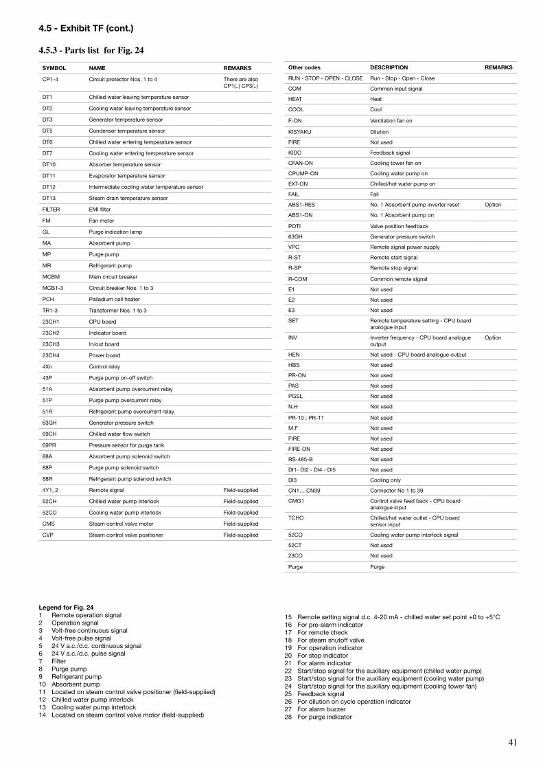
�1
4.5 - exhibit TF (cont.)
4.5.3 - Parts list for Fig. 24
sYMBoL NAMe reMArKs
CP1-4 Circuit protector Nos. 1 to 4 there are also CP1(..) CP3(..)
Dt1 Chilled water leaving temperature sensor
Dt2 Cooling water leaving temperature sensor
Dt3 Generator temperature sensor
Dt5 Condenser temperature sensor
Dt6 Chilled water entering temperature sensor
Dt7 Cooling water entering temperature sensor
Dt10 Absorber temperature sensor
Dt11 Evaporator temperature sensor
Dt12 Intermediate cooling water temperature sensor
Dt13 Steam drain temperature sensor
FILtEr EMI filter
FM Fan motor
GL Purge indication lamp
MA Absorbent pump
MP Purge pump
Mr refrigerant pump
MCbM Main circuit breaker
MCb1-3 Circuit breaker Nos. 1 to 3
PCH Palladium cell heater
tr1-3 transformer Nos. 1 to 3
23CH1 CPU board
23CH2 Indicator board
23CH3 In/out board
23CH4 Power board
4Xn Control relay
43P Purge pump on-off switch
51A Absorbent pump overcurrent relay
51P Purge pump overcurrent relay
51r refrigerant pump overcurrent relay
63GH Generator pressure switch
69CH Chilled water flow switch
69Pr Pressure sensor for purge tank
88A Absorbent pump solenoid switch
88P Purge pump solenoid switch
88r refrigerant pump solenoid switch
4Y1, 2 remote signal Field-supplied
52CH Chilled water pump interlock Field-supplied
52Co Cooling water pump interlock Field-supplied
CMS Steam control valve motor Field-supplied
CVP Steam control valve positioner Field-supplied
Legend for Fig. 241 remote operation signal2 operation signal3 Volt-free continuous signal4 Volt-free pulse signal5 24 V a.c./d.c. continuous signal6 24 V a.c./d.c. pulse signal7 Filter 8 Purge pump9 refrigerant pump10 Absorbent pump11 Located on steam control valve positioner (field-suppiied)12 Chilled water pump interlock13 Cooling water pump interlock14 Located on steam control valve motor (field-supplied)
15 remote setting signal d.c. 4-20 mA - chilled water set point +0 to +5°C16 For pre-alarm indicator17 For remote check18 For steam shutoff valve19 For operation indicator20 For stop indicator21 For alarm indicator22 Start/stop signal for the auxiliary equipment (chilled water pump)23 Start/stop signal for the auxiliary equipment (cooling water pump)24 Start/stop signal for the auxiliary equipment (cooling tower fan)25 Feedback signal26 For dilution on cycle operation indicator27 For alarm buzzer28 For purge indicator
other codes DesCrIPTIoN reMArKs
rUN - StoP - oPEN - CLoSE run - Stop - open - Close
CoM Common input signal
HEAt Heat
CooL Cool
F-oN Ventilation fan on
KISYAKU Dilution
FIrE Not used
KIDo Feedback signal
CFAN-oN Cooling tower fan on
CPUMP-oN Cooling water pump on
EXt-oN Chilled/hot water pump on
FAIL Fail
AbS1-rES No. 1 Absorbent pump inverter reset option
AbS1-oN No. 1 Absorbent pump on
PotI Valve position feedback
63GH Generator pressure switch
VPC remote signal power supply
r-St remote start signal
r-SP remote stop signal
r-CoM Common remote signal
E1 Not used
E2 Not used
E3 Not used
SEt remote temperature setting - CPU board analogue input
INV Inverter frequency - CPU board analogue output
option
HEN Not used - CPU board analogue output
HbS Not used
Pr-oN Not used
PAS Not used
PGSL Not used
N.H Not used
Pr-10 ; Pr-11 Not used
M.F Not used
FIrE Not used
FIrE-oN Not used
rS-485-b Not used
DI1- DI2 - DI4 - DI5 Not used
DI3 Cooling only
CN1….CN39 Connector No 1 to 39
CMG1 Control valve feed back - CPU board analogue input
tCHo Chilled/hot water outlet - CPU board sensor input
52Co Cooling water pump interlock signal
52Ct Not used
23Co Not used
Purge Purge
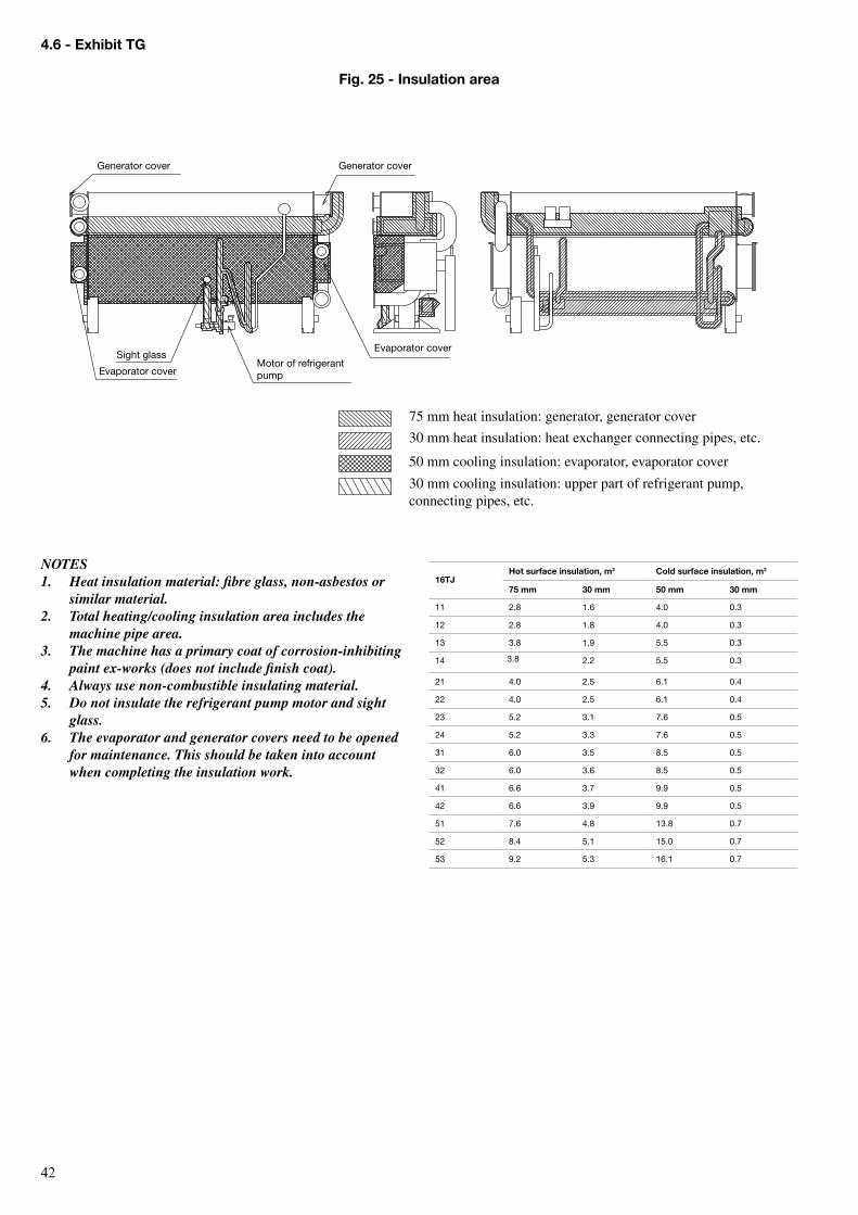
�2
NOTES1. Heat insulation material: fibre glass, non-asbestos or
similar material.2. Total heating/cooling insulation area includes the
machine pipe area.3. The machine has a primary coat of corrosion-inhibiting
paint ex-works (does not include finish coat).4. Always use non-combustible insulating material.5. Do not insulate the refrigerant pump motor and sight
glass.6. The evaporator and generator covers need to be opened
for maintenance. This should be taken into account when completing the insulation work.
16TJHot surface insulation, m2 Cold surface insulation, m2
75 mm 30 mm 50 mm 30 mm
11 2.8 1.6 4.0 0.3
12 2.8 1.8 4.0 0.3
13 3.8 1.9 5.5 0.3
14 3.8 2.2 5.5 0.3
21 4.0 2.5 6.1 0.4
22 4.0 2.5 6.1 0.4
23 5.2 3.1 7.6 0.5
24 5.2 3.3 7.6 0.5
31 6.0 3.5 8.5 0.5
32 6.0 3.6 8.5 0.5
41 6.6 3.7 9.9 0.5
42 6.6 3.9 9.9 0.5
51 7.6 4.8 13.8 0.7
52 8.4 5.1 15.0 0.7
53 9.2 5.3 16.1 0.7
75 mm heat insulation: generator, generator cover
30 mm heat insulation: heat exchanger connecting pipes, etc.
50 mm cooling insulation: evaporator, evaporator cover
30 mm cooling insulation: upper part of refrigerant pump, connecting pipes, etc.
Generator cover Generator cover
Evaporator cover
Evaporator coverSight glass
Motor of refrigerant pump
4.6 - exhibit TG
Fig. 25 - Insulation area
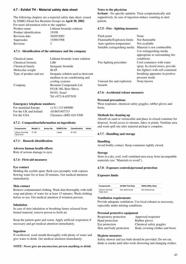
��
notes to the physicianIrritant - No specific antidote. Treat symptomatically and supportively. In case of ingestion induce vomiting in alert patient.
4.7.5 - Fire - fighting measures
Flash point NoneFlammable/Explosion limits Not flammableAuto-ignition temperature Not availableSuitable extinguishing media Material is not combustible.
Use extinguishing media appropriate to surrounding fire conditions.
Fire fighting procedure Cool containers with water spray. In closed stores, provide fire-fighters with self-contained breathing apparatus in positive pressure mode.
Unusual fire and explosion None knownhazards
4.7.6 - Accidental release measures
Personal precautionsWear respirator, chemical safety goggles, rubber gloves and boots.
Methods for cleaning upAbsorb on sand or vermiculite and place in closed container for disposal. Avoid access to streams, lakes or ponds. Ventilate area and wash spill site after material pickup is complete.
4.7.7 - Handling and storage
HandlingAvoid bodily contact. Keep containers tightly closed.
storageStore in a dry, cool, well-ventilated area away from incompatible materials (see "Materials to avoid").
4.7.8 - exposure controls/personal protection
exposure limits
Ventilation requirementsProvide adequate ventilation. Use local exhaust as necessary, especially under misting conditions.
Personal protective equipmentRespiratory protection Approved respiratorHand protection Rubber glovesEye protection Chemical safety gogglesSkin and body protection Body covering clothes and boots
Hygiene measuresSafety shower and eye bath should be provided. Do not eat, drink or smoke until after-work showering and changing clothes.
Components Weight % Annex No. eINeCs No. Classification Notes
Lithium bromide 7550-35-8
47-58 Listed Xi: r41
4.7 - exhibit TH - Material safety data sheet
The following chapters are a material safety data sheet, issued by DSBG (Dead Sea Bromine Group) on April 30, 2002. For more information refer to the supplier.Product name Lithium bromide solutionProduct identification 1910SRevision date 30/05/2002Supersedes 15/09/1998Revision 3
4.7.1 - Identification of the substance and the company
Chemical name Lithium bromide water solutionChemical formula LiBrChemical family Inorganic bromideMolecular weight 86.85Type of product and use Inorganic solution used as desiccant
medium in air conditioning and cooling systems
Company Bromine Compounds Ltd. P.O.B 180, Beer Sheva 84101, Israel Tel +972-8-6297830
emergency telephone numbers:For mainland Europe (+31) 115 689000For the UK and Ireland (01865)407333For the USA Chemtrec (800) 424-9300 4.7.2 - Composition/information on ingredients
4.7.3 - Hazards identification
Adverse human health effectsRisk of serious damage to eyes
4.7.4 - First-aid measures
eye contactHolding the eyelids apart, flush eyes promptly with copious flowing water for at least 20 minutes. Get medical attention immediately.
skin contactRemove contaminated clothing. Wash skin thoroughly with mild soap and plenty of water for at least 15 minutes. Wash clothing before re-use. Get medical attention if irritation persists.
InhalationIn case of mist inhalation or breathing fumes released from heated material, remove person to fresh air.
Keep the patient quiet and warm. Apply artificial respiration if necessary and get medical attention immediately.
IngestionIf swallowed, wash mouth thoroughly with plenty of water and give water to drink. Get medical attention immediately. NOTE: Never give an unconscious person anything to drink.
Components ACGIH-TLV Data osHA (PeL) Data
Lithium bromide 7550-35-8
Not determined Not determined
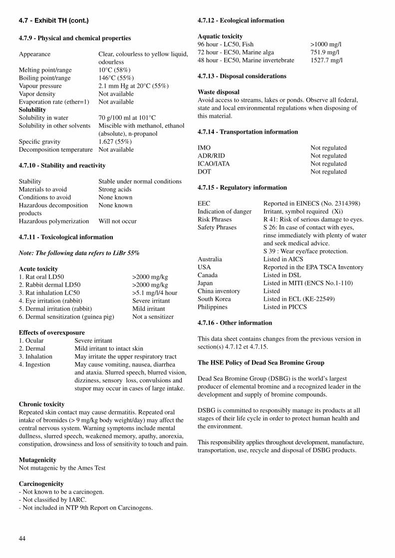
��
4.7 - exhibit TH (cont.)
4.7.9 - Physical and chemical properties
Appearance Clear, colourless to yellow liquid, odourless
Melting point/range 10°C (58%)Boiling point/range 146°C (55%)Vapour pressure 2.1 mm Hg at 20°C (55%)Vapor density Not availableEvaporation rate (ether=1) Not availablesolubilitySolubility in water 70 g/100 ml at 101°CSolubility in other solvents Miscible with methanol, ethanol
(absolute), n-propanolSpecific gravity 1.627 (55%)Decomposition temperature Not available
4.7.10 - stability and reactivity
Stability Stable under normal conditionsMaterials to avoid Strong acidsConditions to avoid None knownHazardous decomposition None known productsHazardous polymerization Will not occur
4.7.11 - Toxicological information
Note: The following data refers to LiBr 55%
Acute toxicity1. Rat oral LD50 >2000 mg/kg2. Rabbit dermal LD50 >2000 mg/kg3. Rat inhalation LC50 >5.1 mg/l/4 hour4. Eye irritation (rabbit) Severe irritant5. Dermal irritation (rabbit) Mild irritant6. Dermal sensitization (guinea pig) Not a sensitizer
effects of overexposure1. Ocular Severe irritant2. Dermal Mild irritant to intact skin3. Inhalation May irritate the upper respiratory tract4. Ingestion May cause vomiting, nausea, diarrhea
and ataxia. Slurred speech, blurred vision, dizziness, sensory loss, convulsions and stupor may occur in cases of large intake.
Chronic toxicityRepeated skin contact may cause dermatitis. Repeated oral intake of bromides (> 9 mg/kg body weight/day) may affect the central nervous system. Warning symptoms include mental dullness, slurred speech, weakened memory, apathy, anorexia, constipation, drowsiness and loss of sensitivity to touch and pain.
MutagenicityNot mutagenic by the Ames Test
Carcinogenicity- Not known to be a carcinogen.- Not classified by IARC.- Not included in NTP 9th Report on Carcinogens.
4.7.12 - ecological information
Aquatic toxicity96 hour - LC50, Fish >1000 mg/l72 hour - EC50, Marine alga 751.9 mg/l48 hour - EC50, Marine invertebrate 1527.7 mg/l
4.7.13 - Disposal considerations
Waste disposalAvoid access to streams, lakes or ponds. Observe all federal, state and local environmental regulations when disposing of this material.
4.7.14 - Transportation information
IMO Not regulatedADR/RID Not regulatedICAO/IATA Not regulatedDOT Not regulated
4.7.15 - Regulatory information
EEC Reported in EINECS (No. 2314398)Indication of danger Irritant, symbol required (Xi)Risk Phrases R 41: Risk of serious damage to eyes.Safety Phrases S 26: In case of contact with eyes,
rinse immediately with plenty of water and seek medical advice. S 39 : Wear eye/face protection.
Australia Listed in AICSUSA Reported in the EPA TSCA InventoryCanada Listed in DSLJapan Listed in MITI (ENCS No.1-110)China inventory ListedSouth Korea Listed in ECL (KE-22549)Philippines Listed in PICCS
4.7.16 - other information
This data sheet contains changes from the previous version in section(s) 4.7.12 et 4.7.15.
The Hse Policy of Dead sea Bromine Group
Dead Sea Bromine Group (DSBG) is the world’s largest producer of elemental bromine and a recognized leader in the development and supply of bromine compounds.
DSBG is committed to responsibly manage its products at all stages of their life cycle in order to protect human health and the environment.
This responsibility applies throughout development, manufacture, transportation, use, recycle and disposal of DSBG products.
��
4.7 - exhibit TH (cont.)
Within this framework DsBG is committed to:1. Comply with national and international regulatory
requirements2. Conform to the ISO 14001 and OHSAS 18001 require-
ments for environmental and occupational health & safety management systems and periodically evaluate performance as part of the company’s existing quality audits system
3. Design products and processes which prevent risk to health and the environment at production sites and along the supply chain
4. Improve efficiency in use of energy & natural resources, promote recycling and waste management through safe & environmentally sound end of life programs
5. Work for continual improvement in HSE performance6. Regularly assess and responsibly manage health, safety
and environmental risks associated with products and processes
7. Educate and train all managers and employees to improve their HSE performance
8. Distribute updated information concerning its policy and products to its workers, customers and other interested parties through Material Safety Data Sheet (MSDS), workers’ safety sheets and through the DSBG Internet Site
9. Develop business relationships with responsible suppliers, transporters and distributors and provide them with HSE support, information and training
10. Support Product Stewardship programs in cooperation with customers, distributors and transporters
11. Allocate the necessary resources for implementation of this policy
DsBG DisclaimerAlthough the information and recommendations set forth herein (herinafter "information") are presented in good faith and believed to be correct as of the date hereof, Bromine Compounds Ltd. makes no representations as to the completeness or accuracy thereof.
Information is supplied upon the condition that the persons receiving same will make their own determination as to its safety and suitability for their purposes prior to use.
In no event will Bromine Compounds Ltd. be responsible for damages of any nature whatsoever resulting from the use of or reliance upon information.
No representations or warranties, either expressed or implied, of merchantability, fitness for a particular purpose or of any other nature, are made hereunder with respect to information or the product to which the information refers.
Prepared by:HSE Division in ISRAEL
telephone: +/972-8-6297830telefax: +/972-8-6297832
www.dsbg.com
End of safety data sheet
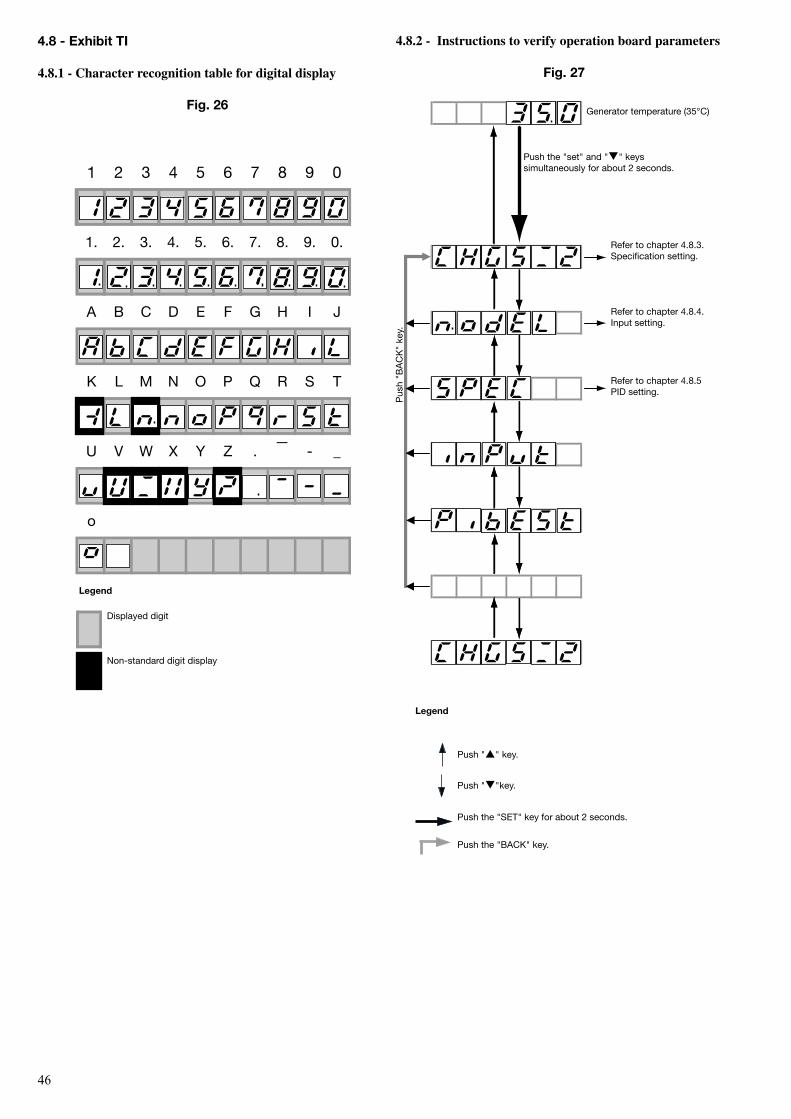
��
1 2 3 4 5 6 7 8 9 0
1. 2. 3. 4. 5. 6. 7. 8. 9. 0.
A B C D E F G H I J
K L M N O P Q R S T
U V W X Y Z . - _
o
_
Displayed digit
Non-standard digit display
Legend
4.8.2 - Instructions to verify operation board parameters
Fig. 27
refer to chapter 4.8.3. Specification setting.
Push the "set" and "q" keys simultaneously for about 2 seconds.
Generator temperature (35°C)
refer to chapter 4.8.4. Input setting.
refer to chapter 4.8.5 PID setting.
Pus
h "b
AC
K"
key.
4.8 - exhibit TI
4.8.1 - Character recognition table for digital display
Fig. 26
Push "p" key.
Push "q"key.
Push the "SEt" key for about 2 seconds.
Push the "bACK" key.
Legend
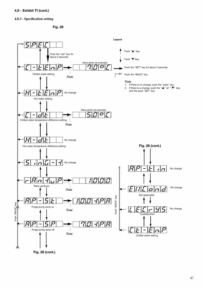
��
Pus
h "b
AC
K"
key. Not applicable
Crystallization
Chilled water setting
No change
No change
No change
Fig. 28 (cont.)
Push "p" key.
Push "q"key.
Push the "SEt" key for about 2 seconds.
Push the "bACK" key.
Note1. If there is no change, push the "back" key.2. If there is a change, push the "p" or " q" key,
and the push "SEt" key.
Legend
Pus
h "b
AC
K"
key.
Push the "set" key for about 2 seconds.
Value given as example
Chilled water setting
Chilled water temperature difference setting
Hot water temperature difference setting
Purge pump lamp on
Value given as example
Hot water setting
Purge pump lamp off
rank up/down
Note
Note
Note
Note
Note
No change
No change
No change
Fig. 28 (cont.)
4.8 - exhibit TI (cont.)
4.8.3 - specification setting
Fig. 28
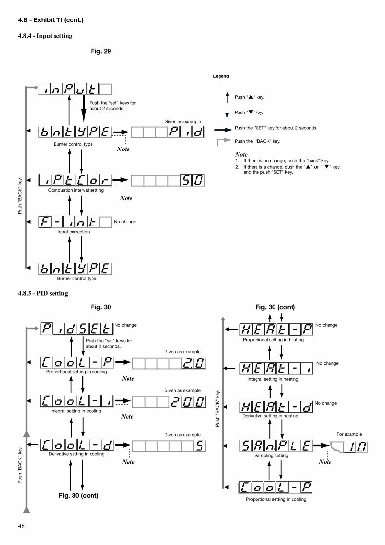
��
Fig. 30 (cont)
4.8.5 - PID setting
Push the "set" keys for about 2 seconds.
Given as example
burner control type
Input correction
Combustion interval setting
burner control type
No change
Note
Note
Pus
h "b
AC
K"
key.
Fig. 30
Push "p" key.
Push "q"key.
Push the "SEt" key for about 2 seconds.
Push the "bACK" key.
Note1. If there is no change, push the "back" key.2. If there is a change, push the "p" or " q" key,
and the push "SEt" key.
Proportional setting in heating
Integral setting in heating
Derivative setting in heating
Sampling setting
Proportional setting in cooling
For example
Note
No change
No change
No change
Pus
h "b
AC
K"
key.
Proportional setting in cooling
Integral setting in cooling
Derivative setting in cooling
Given as example
Given as example
Given as example
No change
Note
Note
Note
Pus
h "b
AC
K"
key.
Fig. 30 (cont)
Legend
4.8 - exhibit TI (cont.)
4.8.4 - Input setting
Fig. 29
Push the "set" keys for about 2 seconds.
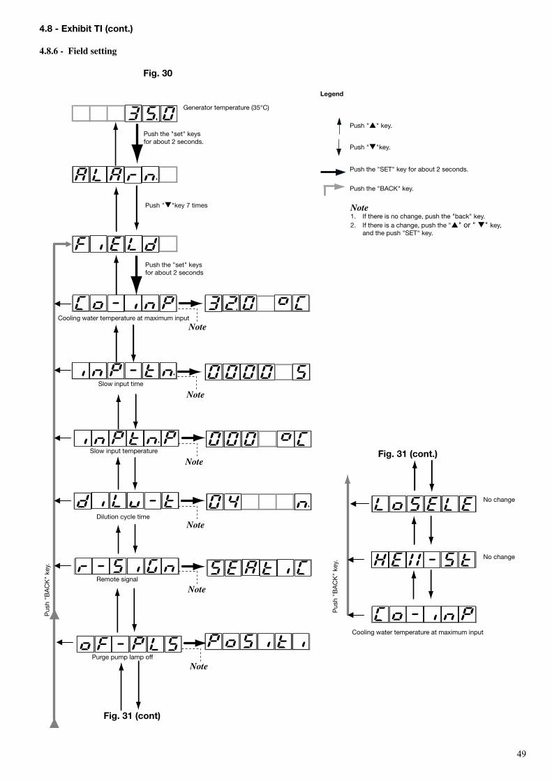
��
Fig. 31 (cont.)
Cooling water temperature at maximum input
Pus
h "b
AC
K"
key.
Push "p" key.
Push "q"key.
Push the "SEt" key for about 2 seconds.
Push the "bACK" key.
Note1. If there is no change, push the "back" key.2. If there is a change, push the "p" or " q" key,
and the push "SEt" key.
Push the "set" keys for about 2 seconds.
Push "q"key 7 times
Push the "set" keys for about 2 seconds
Cooling water temperature at maximum input
Slow input time
Slow input temperature
Dilution cycle time
remote signal
Purge pump lamp off
Fig. 31 (cont)
Pus
h "b
AC
K"
key.
Note
Note
Note
Note
Note
Note
Generator temperature (35°C)
Legend
4.8 - exhibit TI (cont.)
4.8.6 - Field setting
Fig. 30
No change
No change
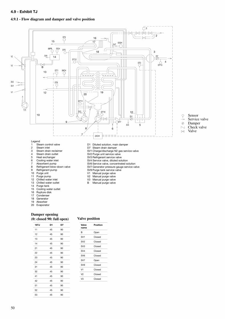
�0
D1 Diluted solution, main damperD7 Steam drain damperSV1 Charge/discharge N2 gas service valveSV2 Purge unit service valveSV3 refrigerant service valveSV4 Service valve, diluted solutionSV6 Service valve, concentrated solutionSV7 Generator pressure gauge service valveSV9 Purge tank service valveV1 Manual purge valveV2 Manual purge valveV3 Manual purge valveb Manual purge valve
16TJ D1 D7
11 45 90
12 45 90
13 45 90
14 45 90
21 45 90
22 45 90
23 45 90
24 45 90
31 45 90
32 45 90
41 45 90
42 45 90
51 45 90
52 45 90
53 45 90
Damper opening (0: closed 90: full open)
Valve name
Position
b open
SV1 Closed
SV2 Closed
SV3 Closed
SV4 Closed
SV6 Closed
SV7 open
SV9 Closed
V1 Closed
V2 Closed
V3 Closed
Valve position
Legend1 Steam control valve2 Steam inlet3 Steam drain reclaimer4 Steam drain outlet5 Heat exchanger6 Cooling water inlet7 Absorbent pump8 refrigerant blow-down valve9 refrigerant pump10 Purge unit11 Purge pump12 Chilled water inlet13 Chilled water outlet14 Purge tank15 Cooling water outlet16 rupture disk17 Condenser18 Generator19 Absorber20 Evaporator
4.9.1 - Flow diagram and damper and valve position
4.9 - exhibit TJ
23CH
DT11
SV3
DT3
63GHSV7
SV4
D1
SV6
DT7
D7
DT13
DT12
69PR PCH
DT2
DT5
DT1 69CH
DT6
DT10
V1
SV1
SV2
V3
V2 SV9
SensorService valveDamperCheck valveValve
8 65
7
1
2
3
9
10
11
12
13
1516
17
18
2019
4
14
b

�1

Order No.: 11�1�-��, 0�.200�. Supersedes order No.: New Manufactured by: Sanyo Electric Co. Ltd. Dalian, PR China Manufacturer reserves the right to change any product specifications without notice. Printed in the Netherlands on totally chlorine-free paper.
GB/T-24001 to ISO14001:1996