MANUAL NO. TOEP C710606 26B
YASKAWA AC Drive-J1000Compact V/f Control Drive
Quick Start GuideType: CIMR-JUModels: 200 V Class, Three-Phase Input: 0.1 to 5.5 kW
200 V Class, Single-Phase Input: 0.1 to 2.2 kW400 V Class, Three-Phase Input: 0.2 to 5.5 kW
To properly use the product, read this manual thoroughly and retain for easy reference, inspection, and maintenance. Ensure the end user receives this manual.
Contém manual suplementar em Português.
Receiving 1Mechanical Installation 2
Electrical Installation 3Start-Up Programming &
Operation 4Troubleshooting 5
Periodic Inspection & Maintenance 6
Specifications A
Parameter List B
Standards Compliance C
Peripheral Devices & Options 7
This Page Intentionally Blank
2 YASKAWA ELECTRIC TOEP C710606 26B YASKAWA AC Drive – J1000 Quick Start Guide
Copyright © 2008 YASKAWA ELECTRIC CORPORATION. All rights reserved.All rights reserved. No part of this publication may be reproduced, stored in a retrieval system,or transmitted, in any form or by any means, mechanical, electronic, photocopying, recording,or otherwise, without the prior written permission of Yaskawa. No patent liability is assumedwith respect to the use of the information contained herein. Moreover, because Yaskawa isconstantly striving to improve its high-quality products, the information contained in thismanual is subject to change without notice. Every precaution has been taken in the preparationof this manual. Yaskawa assumes no responsibility for errors or omissions. Neither is anyliability assumed for damages resulting from the use of the information contained in thispublication.
Table of Contentsi. PREFACE & GENERAL SAFETY ........................9
i.1 Preface .................................................................. 10Applicable Documentation ..........................................10Symbols..................................................................10Terms and Abbreviations............................................10
i.2 General Safety ....................................................... 11Supplemental Safety Information..................................11Safety Messages ......................................................12Drive Label Warnings ................................................15Warranty Information .................................................16Quick Reference.......................................................16
1. RECEIVING .........................................................171.1 Section Safety........................................................ 181.2 Model Number and Nameplate Check.................... 19
Nameplate...............................................................191.3 Component Names ................................................ 22
IP20/Open-Chassis ...................................................22Front Views .............................................................24
2. MECHANICAL INSTALLATION .........................25
YASKAWA ELECTRIC TOEP C710606 26B YASKAWA AC Drive – J1000 Quick Start Guide 3
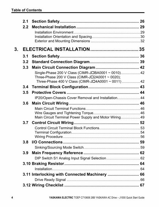
2.1 Section Safety.................................................................. 262.2 Mechanical Installation .................................................... 29
Installation Environment .......................................................29Installation Orientation and Spacing........................................30Exterior and Mounting Dimensions .........................................32
3. ELECTRICAL INSTALLATION....................................353.1 Section Safety.................................................................. 363.2 Standard Connection Diagram......................................... 393.3 Main Circuit Connection Diagram.................................... 42
Single-Phase 200 V Class (CIMR-JoBA0001 ~ 0010)................42Three-Phase 200 V Class (CIMR-Jo2A0001 ~ 0020);Three-Phase 400 V Class (CIMR-Jo4A0001 ~ 0011) ...............42
3.4 Terminal Block Configuration.......................................... 433.5 Protective Covers ............................................................ 44
IP20/Open-Chassis Cover Removal and Installation...................443.6 Main Circuit Wiring .......................................................... 46
Main Circuit Terminal Functions .............................................46Wire Gauges and Tightening Torque.......................................46Main Circuit Terminal Power Supply and Motor Wiring................49
3.7 Control Circuit Wiring...................................................... 52Control Circuit Terminal Block Functions..................................53Terminal Configuration.........................................................54Wiring Procedure ................................................................56
3.8 I/O Connections ............................................................... 59Sinking/Sourcing Mode Switch...............................................59
3.9 Main Frequency Reference .............................................. 62DIP Switch S1 Analog Input Signal Selection ............................62
3.10 Braking Resistor.............................................................. 64Installation.........................................................................64
3.11 Interlocking with Connected Machinery .......................... 66Drive Ready Signal .............................................................66
3.12 Wiring Checklist .............................................................. 67
Table of Contents
4 YASKAWA ELECTRIC TOEP C710606 26B YASKAWA AC Drive – J1000 Quick Start Guide

4. START-UP PROGRAMMING & OPERATION............. 694.1 Section Safety.................................................................. 704.2 Using the Digital LED Operator........................................ 73
Keys, Displays, and LEDs.....................................................73Digital Text Display .............................................................75LED Screen Displays...........................................................76LO/RE LED and RUN LED Indications ....................................76Menu Structure for Digital LED Operator..................................78
4.3 The Drive and Programming Modes ................................ 79Navigating the Drive and Programming Modes..........................80Changing Parameter Settings or Values ..................................83Verifying Parameter Changes: Verify Menu ..............................84Switching Between LOCAL and REMOTE................................85Parameters Available in the Setup Group.................................86
4.4 Start-up Flowchart ........................................................... 87Flowchart: Basic Start-up......................................................87
4.5 Basic Operation ............................................................... 88Initialize Parameter Values: A1-03..........................................88Frequency Reference Source: b1-01.......................................88Run Command Input Selection: b1-02.....................................90Stopping Method Selection: b1-03..........................................92Acceleration/Deceleration: C1-01 to C1-04...............................93Drive Duty and Carrier Frequency Selection: C6-01 and C6-02......................................................................................95
Multi-Step Speed Operation (4-Step Speed) .............................97E1: V/f Characteristics ....................................................... 101Motor Parameters: E2-01 to E2-03 ....................................... 104Digital Output: H2-01 ......................................................... 105Analog Outputs: H4-01 to H4-03 .......................................... 105Motor Protection: L1-01 and L1-02 ....................................... 107Drive Status Monitors: U1-01 to U4-13 .................................. 110
4.6 Powering Up the Drive ....................................................112Powering Up the Drive and Operation Status Display ............... 112V/f Pattern Setting............................................................. 113
4.7 No-Load Operation Test Run ..........................................114No-Load Operation Test Run............................................... 114
Table of Contents
YASKAWA ELECTRIC TOEP C710606 26B YASKAWA AC Drive – J1000 Quick Start Guide 5
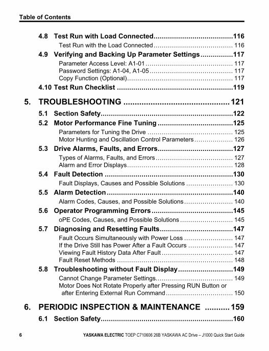
4.8 Test Run with Load Connected.......................................116Test Run with the Load Connected....................................... 116
4.9 Verifying and Backing Up Parameter Settings................117Parameter Access Level: A1-01 ........................................... 117Password Settings: A1-04, A1-05......................................... 117Copy Function (Optional).................................................... 117
4.10 Test Run Checklist .........................................................119
5. TROUBLESHOOTING ...............................................1215.1 Section Safety.................................................................1225.2 Motor Performance Fine Tuning .....................................125
Parameters for Tuning the Drive .......................................... 125Motor Hunting and Oscillation Control Parameters ................... 126
5.3 Drive Alarms, Faults, and Errors.....................................127Types of Alarms, Faults, and Errors ...................................... 127Alarm and Error Displays.................................................... 128
5.4 Fault Detection ...............................................................130Fault Displays, Causes and Possible Solutions ....................... 130
5.5 Alarm Detection ..............................................................140Alarm Codes, Causes, and Possible Solutions ........................ 140
5.6 Operator Programming Errors........................................145oPE Codes, Causes, and Possible Solutions .......................... 145
5.7 Diagnosing and Resetting Faults....................................147Fault Occurs Simultaneously with Power Loss ........................ 147If the Drive Still has Power After a Fault Occurs ...................... 147Viewing Fault History Data After Fault ................................... 147Fault Reset Methods ......................................................... 148
5.8 Troubleshooting without Fault Display...........................149Cannot Change Parameter Settings...................................... 149Motor Does Not Rotate Properly after Pressing RUN Button orafter Entering External Run Command................................. 150
6. PERIODIC INSPECTION & MAINTENANCE ........... 1596.1 Section Safety.................................................................160
Table of Contents
6 YASKAWA ELECTRIC TOEP C710606 26B YASKAWA AC Drive – J1000 Quick Start Guide
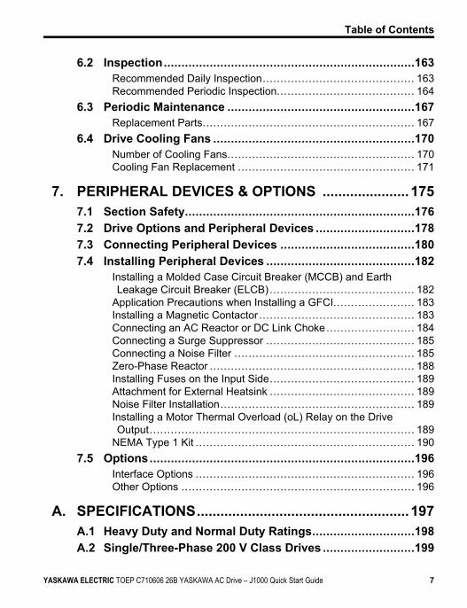
6.2 Inspection.......................................................................163Recommended Daily Inspection........................................... 163Recommended Periodic Inspection....................................... 164
6.3 Periodic Maintenance .....................................................167Replacement Parts............................................................ 167
6.4 Drive Cooling Fans .........................................................170Number of Cooling Fans..................................................... 170Cooling Fan Replacement .................................................. 171
7. PERIPHERAL DEVICES & OPTIONS ...................... 1757.1 Section Safety.................................................................1767.2 Drive Options and Peripheral Devices ............................1787.3 Connecting Peripheral Devices ......................................1807.4 Installing Peripheral Devices ..........................................182
Installing a Molded Case Circuit Breaker (MCCB) and EarthLeakage Circuit Breaker (ELCB) ......................................... 182
Application Precautions when Installing a GFCI....................... 183Installing a Magnetic Contactor ............................................ 183Connecting an AC Reactor or DC Link Choke......................... 184Connecting a Surge Suppressor .......................................... 185Connecting a Noise Filter ................................................... 185Zero-Phase Reactor .......................................................... 188Installing Fuses on the Input Side......................................... 189Attachment for External Heatsink ......................................... 189Noise Filter Installation....................................................... 189Installing a Motor Thermal Overload (oL) Relay on the DriveOutput........................................................................... 189
NEMA Type 1 Kit .............................................................. 1907.5 Options...........................................................................196
Interface Options .............................................................. 196Other Options .................................................................. 196
A. SPECIFICATIONS......................................................197A.1 Heavy Duty and Normal Duty Ratings.............................198A.2 Single/Three-Phase 200 V Class Drives ..........................199
Table of Contents
YASKAWA ELECTRIC TOEP C710606 26B YASKAWA AC Drive – J1000 Quick Start Guide 7
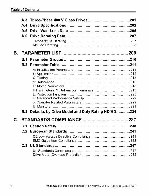
A.3 Three-Phase 400 V Class Drives .....................................201A.4 Drive Specifications........................................................202A.5 Drive Watt Loss Data ......................................................205A.6 Drive Derating Data.........................................................207
Temperature Derating........................................................ 207Altitude Derating ............................................................... 208
B. PARAMETER LIST ....................................................209B.1 Parameter Groups ..........................................................210B.2 Parameter Table..............................................................211
A: Initialization Parameters ................................................. 211b: Application ................................................................... 212C: Tuning ........................................................................ 213d: References .................................................................. 216E: Motor Parameters ......................................................... 218H Parameters: Multi-Function Terminals ................................ 219L: Protection Function ........................................................ 225n: Advanced Performance Set-Up ........................................ 229o: Operator Related Parameters .......................................... 229U: Monitors...................................................................... 231
B.3 Defaults by Drive Model and Duty Rating ND/HD............234
C. STANDARDS COMPLIANCE ....................................237C.1 Section Safety.................................................................238C.2 European Standards.......................................................241
CE Low Voltage Directive Compliance .................................. 241EMC Guidelines Compliance............................................... 242
C.3 UL Standards..................................................................247UL Standards Compliance .................................................. 247Drive Motor Overload Protection .......................................... 252
Table of Contents
8 YASKAWA ELECTRIC TOEP C710606 26B YASKAWA AC Drive – J1000 Quick Start Guide
Preface & GeneralSafety
This section provides safety messages pertinent to this productthat, if not heeded, may result in fatality, personal injury, orequipment damage. Yaskawa is not responsible for theconsequences of ignoring these instructions.
i.1 PREFACE.........................................................10i.2 GENERAL SAFETY...........................................11
i
YASKAWA ELECTRIC TOEP C710606 26B YASKAWA AC Drive – J1000 Quick Start Guide 9
i.1 PrefaceYaskawa manufactures products used as components in a wide variety of industrial systemsand equipment. The selection and application of Yaskawa products remain the responsibilityof the equipment manufacturer or end user. Yaskawa accepts no responsibility for the way itsproducts are incorporated into the final system design. Under no circumstances should anyYaskawa product be incorporated into any product or design as the exclusive or sole safetycontrol. Without exception, all controls should be designed to detect faults dynamically andfail safely under all circumstances. All systems or equipment designed to incorporate a productmanufactured by Yaskawa must be supplied to the end user with appropriate warnings andinstructions as to the safe use and operation of that part. Any warnings provided by Yaskawamust be promptly provided to the end user. Yaskawa offers an express warranty only as to thequality of its products in conforming to standards and specifications published in the Yaskawamanual. NO OTHER WARRANTY, EXPRESS OR IMPLIED, IS OFFERED. Yaskawaassumes no liability for any personal injury, property damage, losses, or claims arising frommisapplication of its products.
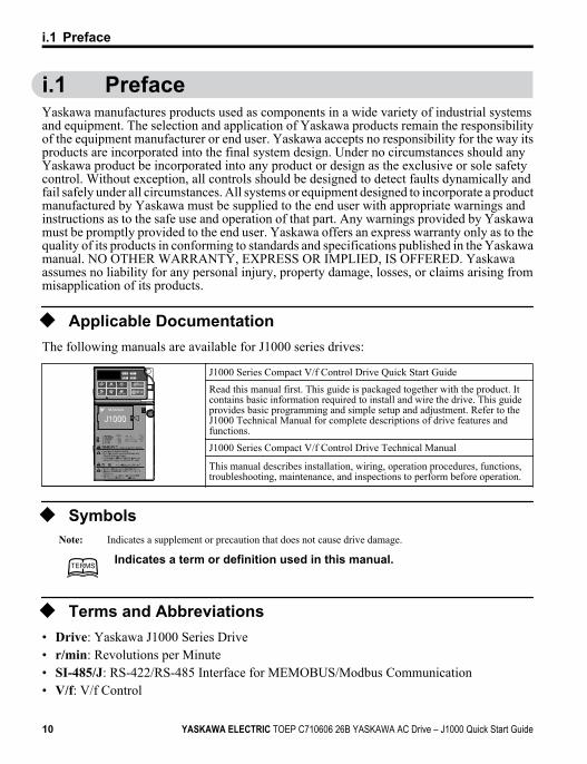
u Applicable DocumentationThe following manuals are available for J1000 series drives:
J1000 Series Compact V/f Control Drive Quick Start Guide
Read this manual first. This guide is packaged together with the product. Itcontains basic information required to install and wire the drive. This guideprovides basic programming and simple setup and adjustment. Refer to theJ1000 Technical Manual for complete descriptions of drive features andfunctions.
J1000 Series Compact V/f Control Drive Technical Manual
This manual describes installation, wiring, operation procedures, functions,troubleshooting, maintenance, and inspections to perform before operation.
u SymbolsNote: Indicates a supplement or precaution that does not cause drive damage.
TERMSTERMSIndicates a term or definition used in this manual.
u Terms and Abbreviations• Drive: Yaskawa J1000 Series Drive• r/min: Revolutions per Minute• SI-485/J: RS-422/RS-485 Interface for MEMOBUS/Modbus Communication• V/f: V/f Control
i.1 Preface
10 YASKAWA ELECTRIC TOEP C710606 26B YASKAWA AC Drive – J1000 Quick Start Guide
i.2 General Safety
u Supplemental Safety InformationGeneral Precautions
• The diagrams in this manual may be indicated without covers or safety shields to show details. Restorecovers or shields before operating the drive and run the drive according to the instructions describedin this manual.
• Any illustrations, photographs, or examples used in this manual are provided as examples only andmay not apply to all products to which this manual is applicable.
• The products and specifications described in this manual or the content and presentation of the manualmay be changed without notice to improve the product and/or the manual.
• When ordering a new copy of the manual due to damage or loss, contact your Yaskawa representativeor the nearest Yaskawa sales office and provide the manual number shown on the front cover.
• If nameplate becomes worn or damaged, order a replacement from your Yaskawa representative orthe nearest Yaskawa sales office.
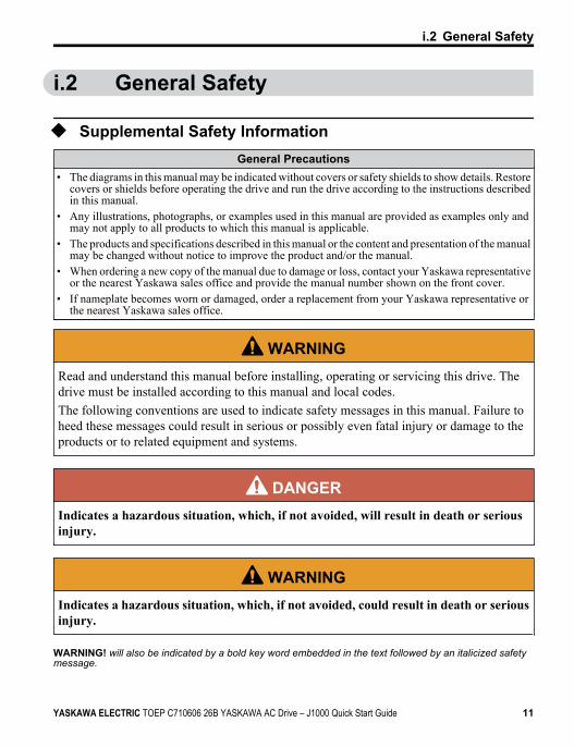
WARNINGRead and understand this manual before installing, operating or servicing this drive. Thedrive must be installed according to this manual and local codes.The following conventions are used to indicate safety messages in this manual. Failure toheed these messages could result in serious or possibly even fatal injury or damage to theproducts or to related equipment and systems.
DANGERIndicates a hazardous situation, which, if not avoided, will result in death or seriousinjury.
WARNINGIndicates a hazardous situation, which, if not avoided, could result in death or seriousinjury.
WARNING! will also be indicated by a bold key word embedded in the text followed by an italicized safetymessage.
i.2 General Safety
YASKAWA ELECTRIC TOEP C710606 26B YASKAWA AC Drive – J1000 Quick Start Guide 11
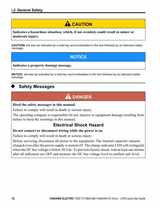
CAUTIONIndicates a hazardous situation, which, if not avoided, could result in minor ormoderate injury.
CAUTION! will also be indicated by a bold key word embedded in the text followed by an italicized safetymessage.
NOTICE
Indicates a property damage message.
NOTICE: will also be indicated by a bold key word embedded in the text followed by an italicized safetymessage.
u Safety Messages
DANGERHeed the safety messages in this manual.Failure to comply will result in death or serious injury.The operating company is responsible for any injuries or equipment damage resulting fromfailure to heed the warnings in this manual.
Electrical Shock HazardDo not connect or disconnect wiring while the power is on.Failure to comply will result in death or serious injury.Before servicing, disconnect all power to the equipment. The internal capacitor remainscharged even after the power supply is turned off. The charge indicator LED will extinguishwhen the DC bus voltage is below 50 Vdc. To prevent electric shock, wait at least one minuteafter all indicators are OFF and measure the DC bus voltage level to confirm safe level.
i.2 General Safety
12 YASKAWA ELECTRIC TOEP C710606 26B YASKAWA AC Drive – J1000 Quick Start Guide
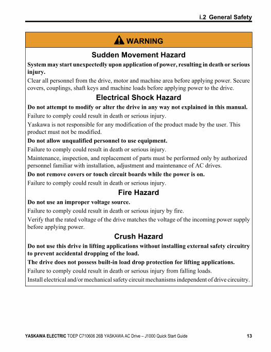
WARNING
Sudden Movement HazardSystem may start unexpectedly upon application of power, resulting in death or seriousinjury.Clear all personnel from the drive, motor and machine area before applying power. Securecovers, couplings, shaft keys and machine loads before applying power to the drive.
Electrical Shock HazardDo not attempt to modify or alter the drive in any way not explained in this manual.Failure to comply could result in death or serious injury.Yaskawa is not responsible for any modification of the product made by the user. Thisproduct must not be modified.Do not allow unqualified personnel to use equipment.Failure to comply could result in death or serious injury.Maintenance, inspection, and replacement of parts must be performed only by authorizedpersonnel familiar with installation, adjustment and maintenance of AC drives.Do not remove covers or touch circuit boards while the power is on.Failure to comply could result in death or serious injury.
Fire HazardDo not use an improper voltage source.Failure to comply could result in death or serious injury by fire.Verify that the rated voltage of the drive matches the voltage of the incoming power supplybefore applying power.
Crush HazardDo not use this drive in lifting applications without installing external safety circuitryto prevent accidental dropping of the load.The drive does not possess built-in load drop protection for lifting applications.Failure to comply could result in death or serious injury from falling loads.Install electrical and/or mechanical safety circuit mechanisms independent of drive circuitry.
i.2 General Safety
YASKAWA ELECTRIC TOEP C710606 26B YASKAWA AC Drive – J1000 Quick Start Guide 13
CAUTION
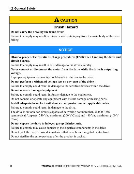
Crush HazardDo not carry the drive by the front cover.Failure to comply may result in minor or moderate injury from the main body of the drivefalling.
NOTICE
Observe proper electrostatic discharge procedures (ESD) when handling the drive andcircuit boards.Failure to comply may result in ESD damage to the drive circuitry.Never connect or disconnect the motor from the drive while the drive is outputtingvoltage.Improper equipment sequencing could result in damage to the drive.Do not perform a withstand voltage test on any part of the drive.Failure to comply could result in damage to the sensitive devices within the drive.Do not operate damaged equipment.Failure to comply could result in further damage to the equipment.Do not connect or operate any equipment with visible damage or missing parts.Install adequate branch circuit short circuit protection per applicable codes.Failure to comply could result in damage to the drive.The drive is suitable for circuits capable of delivering not more than 31,000 RMSsymmetrical Amperes, 240 Vac maximum (200 V Class) and 480 Vac maximum (400 VClass).Do not expose the drive to halogen group disinfectants.Failure to comply may cause damage to the electrical components in the drive.Do not pack the drive in wooden materials that have been fumigated or sterilized.Do not sterilize the entire package after the product is packed.
i.2 General Safety
14 YASKAWA ELECTRIC TOEP C710606 26B YASKAWA AC Drive – J1000 Quick Start Guide
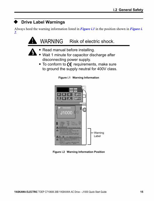
u Drive Label WarningsAlways heed the warning information listed in Figure i.1 in the position shown in Figure i.2.
Risk of electric shock.WARNINGRead manual before installing.Wait 1 minute for capacitor discharge afterdisconnecting power supply.To conform to requirements, make sureto ground the supply neutral for 400V class.
Figure i.1 Warning Information
WarningLabel
Figure i.2 Warning Information Position
i.2 General Safety
YASKAWA ELECTRIC TOEP C710606 26B YASKAWA AC Drive – J1000 Quick Start Guide 15
u Warranty Information
n RestrictionsThe drive was not designed or manufactured for use in devices or systems that may directlyaffect or threaten human lives or health.Customers who intend to use the product described in this manual for devices or systemsrelating to transportation, health care, space aviation, atomic power, electric power, or inunderwater applications must first contact their Yaskawa representatives or the nearestYaskawa sales office.This product has been manufactured under strict quality-control guidelines. However, if thisproduct is to be installed in any location where failure of this product could involve or resultin a life-and-death situation or loss of human life or in a facility where failure may cause aserious accident or physical injury, safety devices must be installed to minimize the likelihoodof any accident.
u Quick ReferenceRun a Motor of One-Frame Larger Capacity
When using this drive for variable torque loads such as fans and pumps, a motor one frame size larger can be used.
Know the Details of Safety MeasuresThe functions listed below affect the safe operation of the drive. Ensure that the settings fit the application requirementsprior to operation.
Safe operations. Run by power on. Parameter setting b1-17.
LED operator stop key priority selection. Parameter o2-02.
Enter press required after changing the keypad frequency reference. Parameter o2-05.
Operation interlock when program mode is selected. Parameter b1-08.
Standards Compliance
Refer to European Standards on page 241 and Refer to UL Standards on page 247.
i.2 General Safety
16 YASKAWA ELECTRIC TOEP C710606 26B YASKAWA AC Drive – J1000 Quick Start Guide
ReceivingThis chapter describes the proper inspections to perform afterreceiving the drive and illustrates the different enclosure typesand components.
1.1 SECTION SAFETY.............................................181.2 MODEL NUMBER AND NAMEPLATE CHECK
.........................................................................191.3 COMPONENT NAMES.......................................22
1
YASKAWA ELECTRIC TOEP C710606 26B YASKAWA AC Drive – J1000 Quick Start Guide 17
1.1 Section Safety
CAUTIONDo not carry the drive by the front cover.Failure to comply may cause the main body of the drive to fall, resulting in minor or moderateinjury.
NOTICE
Observe proper electrostatic discharge procedures (ESD) when handling the drive andcircuit boards.Failure to comply may result in ESD damage to the drive circuitry.A motor connected to a PWM drive may operate at a higher temperature than a utility-fed motor and the operating speed range may reduce motor cooling capacity.Ensure that the motor is suitable for drive duty and/or the motor service factor is adequateto accommodate the additional heating with the intended operating conditions.
1.1 Section Safety
18 YASKAWA ELECTRIC TOEP C710606 26B YASKAWA AC Drive – J1000 Quick Start Guide
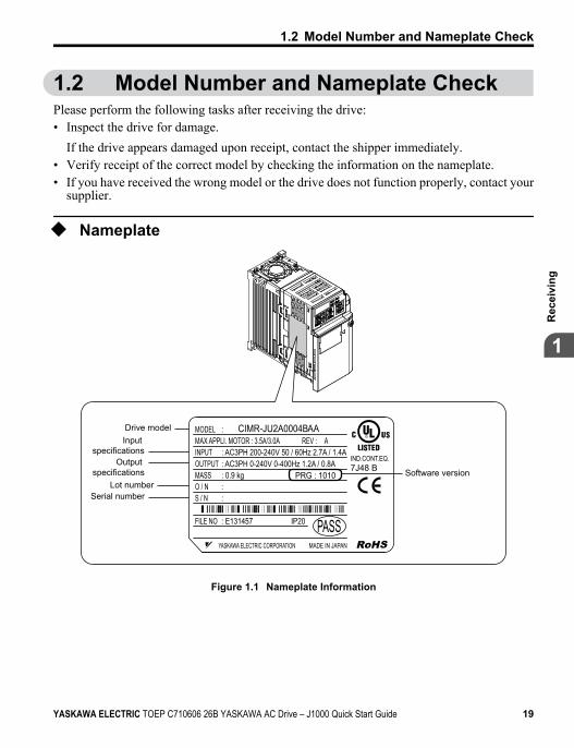
1.2 Model Number and Nameplate CheckPlease perform the following tasks after receiving the drive:• Inspect the drive for damage.
If the drive appears damaged upon receipt, contact the shipper immediately.• Verify receipt of the correct model by checking the information on the nameplate.• If you have received the wrong model or the drive does not function properly, contact your
supplier.
u Nameplate
PRG : 1010
IND.CONT.EQ.7J48 B
CIMR-JU2A0004BAA
YASKAWA ELECTRIC CORPORATION MADE IN JAPAN
:
: AC3PH 200-240V 50 / 60Hz 2.7A / 1.4A: AC3PH 0-240V 0-400Hz 1.2A / 0.8A: 0.9 kg: :
: E131457 IP20 PASS
MODEL MAX APPLI. MOTOR : 3.5A/3.0A REV : AINPUTOUTPUTMASSO / NS / N
FILE NO
Drive modelInput
specificationsOutput
specificationsLot number
Serial number
Software version
Figure 1.1 Nameplate Information
1.2 Model Number and Nameplate Check
YASKAWA ELECTRIC TOEP C710606 26B YASKAWA AC Drive – J1000 Quick Start Guide 19
1
Rec
eivi
ng
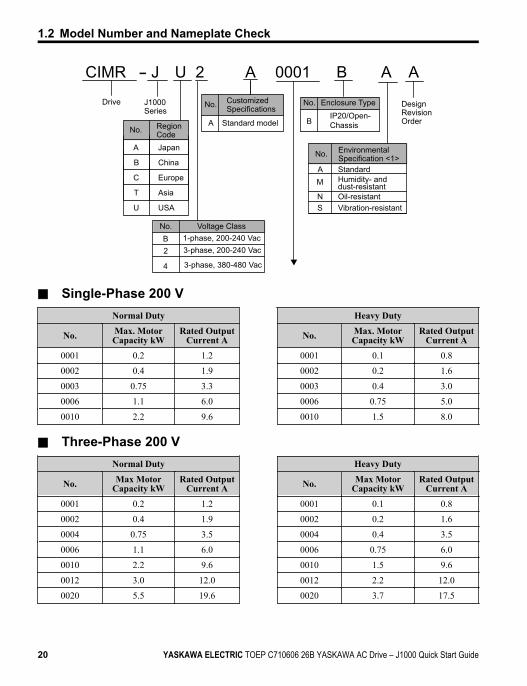
CIMR - J U 2 A 0001 B A A
Drive J1000 Series
Design Revision Order
No. Enclosure Type IP20/Open-ChassisB
No. Environmental Specification <1>
AM
NS
StandardHumidity- and dust-resistantOil-resistant Vibration-resistant
No. CustomizedSpecifications
A Standard modelNo. Region
CodeA Japan
No. Voltage ClassB 1-phase, 200-240 Vac
3-phase, 380-480 Vac
3-phase, 200-240 Vac 2
4
B China
C Europe
T Asia
U USA
n Single-Phase 200 VNormal Duty Heavy Duty
No. Max. MotorCapacity kW
Rated OutputCurrent A No. Max. Motor
Capacity kWRated Output
Current A0001 0.2 1.2 0001 0.1 0.8
0002 0.4 1.9 0002 0.2 1.6
0003 0.75 3.3 0003 0.4 3.0
0006 1.1 6.0 0006 0.75 5.0
0010 2.2 9.6 0010 1.5 8.0
n Three-Phase 200 VNormal Duty Heavy Duty
No. Max MotorCapacity kW
Rated OutputCurrent A No. Max Motor
Capacity kWRated Output
Current A0001 0.2 1.2 0001 0.1 0.8
0002 0.4 1.9 0002 0.2 1.6
0004 0.75 3.5 0004 0.4 3.5
0006 1.1 6.0 0006 0.75 6.0
0010 2.2 9.6 0010 1.5 9.6
0012 3.0 12.0 0012 2.2 12.0
0020 5.5 19.6 0020 3.7 17.5
1.2 Model Number and Nameplate Check
20 YASKAWA ELECTRIC TOEP C710606 26B YASKAWA AC Drive – J1000 Quick Start Guide
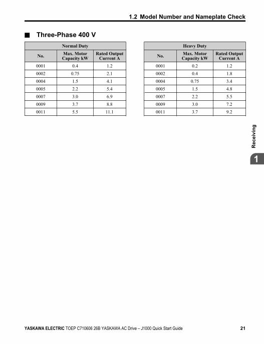
n Three-Phase 400 VNormal Duty Heavy Duty
No. Max. MotorCapacity kW
Rated OutputCurrent A No. Max. Motor
Capacity kWRated Output
Current A0001 0.4 1.2 0001 0.2 1.2
0002 0.75 2.1 0002 0.4 1.8
0004 1.5 4.1 0004 0.75 3.4
0005 2.2 5.4 0005 1.5 4.8
0007 3.0 6.9 0007 2.2 5.5
0009 3.7 8.8 0009 3.0 7.2
0011 5.5 11.1 0011 3.7 9.2
1.2 Model Number and Nameplate Check
YASKAWA ELECTRIC TOEP C710606 26B YASKAWA AC Drive – J1000 Quick Start Guide 21
1
Rec
eivi
ng
1.3 Component NamesThis section illustrates drive components in the IP20/Open-Chassis models.Refer to NEMA Type 1 Kit on page 190 for information on using the NEMA Type 1 Kitoption to create a NEMA Type 1 rating.
u IP20/Open-Chassis
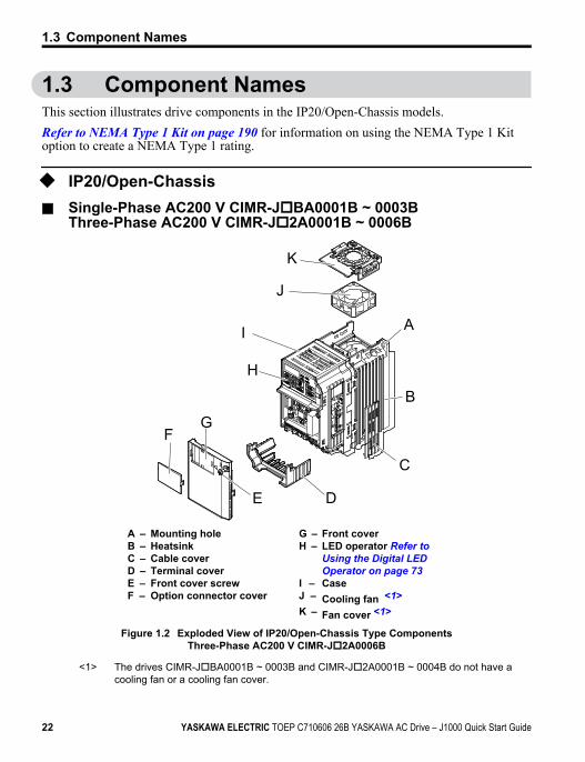
n Single-Phase AC200 V CIMR-JoBA0001B ~ 0003BThree-Phase AC200 V CIMR-Jo2A0001B ~ 0006B
K
A
B
C
DE
G
H
J
I
F
A – Mounting holeB – HeatsinkC – Cable coverD – Terminal coverE – Front cover screwF – Option connector cover
G – Front coverH – LED operator Refer to
Using the Digital LED Operator on page 73
I – CaseJ – Cooling fan <1>K – Fan cover <1>
Figure 1.2 Exploded View of IP20/Open-Chassis Type ComponentsThree-Phase AC200 V CIMR-Jo2A0006B
<1> The drives CIMR-JoBA0001B ~ 0003B and CIMR-Jo2A0001B ~ 0004B do not have acooling fan or a cooling fan cover.
1.3 Component Names
22 YASKAWA ELECTRIC TOEP C710606 26B YASKAWA AC Drive – J1000 Quick Start Guide
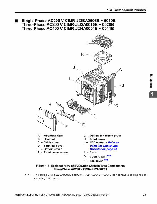
n Single-Phase AC200 V CIMR-JoBA0006B ~ 0010BThree-Phase AC200 V CIMR-Jo2A0010B ~ 0020BThree-Phase AC400 V CIMR-Jo4A0001B ~ 0011B
L
A
B
C
D
F
K
J
I
E
GH
A – Mounting holeB – HeatsinkC – Cable coverD – Terminal coverE – Bottom coverF – Front cover screw
G – Option connector coverH – Front coverI – LED operator Refer to
Using the Digital LED Operator on page 73
J – CaseK – Cooling fan <1>L – Fan cover <1>
Figure 1.3 Exploded view of IP20/Open-Chassis Type ComponentsThree-Phase AC200 V CIMR-Jo2A0012B
<1> The drives CIMR-JoBA0006B and CIMR-Jo4A0001B ~ 0004B do not have a cooling fan ora cooling fan cover.
1.3 Component Names
YASKAWA ELECTRIC TOEP C710606 26B YASKAWA AC Drive – J1000 Quick Start Guide 23
1
Rec
eivi
ng
u Front Views
G
F
AB
CD
E
A
B
C
D
E
F
G
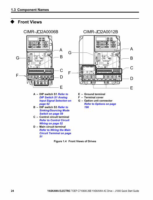
CIMR-J 2A0006B CIMR-J 2A0012B
A – DIP switch S1 Refer to DIP Switch S1 Analog Input Signal Selection on page 62
B – DIP switch S3 Refer to Sinking/Sourcing Mode Switch on page 59
C – Control circuit terminalRefer to Control Circuit Wiring on page 52
D – Main circuit terminalRefer to Wiring the Main Circuit Terminal on page 51
E – Ground terminalF – Terminal coverG – Option unit connector
Refer to Options on page 196
Figure 1.4 Front Views of Drives
1.3 Component Names
24 YASKAWA ELECTRIC TOEP C710606 26B YASKAWA AC Drive – J1000 Quick Start Guide
MechanicalInstallation
This chapter explains how to properly mount and install thedrive.
2.1 SECTION SAFETY.............................................262.2 MECHANICAL INSTALLATION..........................29
2
YASKAWA ELECTRIC TOEP C710606 26B YASKAWA AC Drive – J1000 Quick Start Guide 25
2.1 Section Safety
WARNING
Fire HazardProvide sufficient cooling with a fan or air conditioning unit when installing the driveinside an enclosed panel or cabinet.Failure to comply could result in overheating and fire.The airflow over an IP20/Open-Chassis drive should be less than 50 °C, while an IP20/NEMA Type 1 drive using the NEMA Type 1 Kit option should have an airflow cooler than40 °C.
CAUTION
Crush HazardDo not carry the drive by the front cover.Failure to comply may result in minor or moderate injury from the main body of the drivefalling.
2.1 Section Safety
26 YASKAWA ELECTRIC TOEP C710606 26B YASKAWA AC Drive – J1000 Quick Start Guide
NOTICE
Observe proper electrostatic discharge (ESD) procedures when handling the drive.Failure to comply could result in ESD damage to the drive circuitry.It may be difficult to perform maintenance on the cooling fans of drives installed in avertical row inside an enclosure.Ensure adequate spacing at the top of the drive to perform cooling fan replacement whenrequired.Operating the motor in the low-speed range diminishes the cooling effects, increasesmotor temperature, and may lead to motor damage by overheating.Reduce the motor torque in the low-speed range whenever using a standard blower cooledmotor. If 100% torque is required continuously at low speed, consider using a special driveor vector motor. Select a motor that is compatible with the required load torque and operatingspeed range.Do not operate motors above the maximum rated RPM.Failure to comply may lead to bearing or other mechanical motor failures.The speed range for continuous operation differs according to the lubrication methodand motor manufacturer.If the motor is to be operated at a speed higher than the rated speed, consult with themanufacturer.Continuously operating an oil-lubricated motor in the low-speed range may result in burning.
2.1 Section Safety
YASKAWA ELECTRIC TOEP C710606 26B YASKAWA AC Drive – J1000 Quick Start Guide 27
2
Mec
hani
cal I
nsta
llatio
n
NOTICEWhen the wiring distance is greater than 100 meters, pay special attention to the motorinsulation voltage or use a drive-rated motor.Failure to comply could lead to motor winding failure.Motor vibration may increase when operating a machine in variable-speed mode, ifthat machine previously operated at a constant speed.Install vibration-proof rubber on the motor base or use the frequency jump function to skipa frequency resonating the machine.The motor may require more acceleration torque with drive operation than with acommercial power supply.Set a proper V/f pattern by checking the load torque characteristics of the machine to beused with the motor.The rated input current of submersible motors is higher than the rated input currentof standard motors.Select an appropriate drive according to its rated output current. When the distance betweenthe motor and drive is long, use a cable thick enough to connect the motor to the drive toprevent motor torque reduction.When using an explosion-proof motor, it must be subject to an explosion-proof test inconjunction with the drive.This is also applicable when an existing explosion-proof motor is to be operated with thedrive. Since the drive itself is not explosion-proof, always install it in a safe place.Do not use a drive for a single-phase motor.Replace the motor with a three-phase motor.If an oil-lubricated gearbox or speed reducer is used in the power transmissionmechanism, oil lubrication will be affected when the motor operates only in the lowspeed range.The power transmission mechanism will make noise and experience problems with servicelife and durability if the motor is operated at a speed higher than the rated speed.
2.1 Section Safety
28 YASKAWA ELECTRIC TOEP C710606 26B YASKAWA AC Drive – J1000 Quick Start Guide
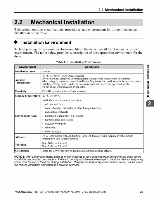
2.2 Mechanical InstallationThis section outlines specifications, procedures, and environment for proper mechanicalinstallation of the drive.
u Installation EnvironmentTo help prolong the optimum performance life of the drive, install the drive in the properenvironment. The table below provides a description of the appropriate environment for thedrive.
Table 2.1 Installation EnvironmentEnvironment Conditions
Installation Area Indoors
AmbientTemperature
-10 °C to +50 °C (IP20/Open-Chassis)Drive reliability improves in environments without wide temperature fluctuations.When using an enclosure panel, install a cooling fan or air conditioner in the area to ensurethat the air temperature inside the enclosure does not exceed the specified levels.Do not allow ice to develop on the drive.
Humidity 95% RH or less and free of condensation
Storage Temperature -20 °C to +60 °C
Surrounding Area
Install the drive in an area free from:• oil mist and dust• metal shavings, oil, water or other foreign materials• radioactive materials• combustible materials (e.g., wood)• harmful gases and liquids• excessive vibration• chlorides• direct sunlight
Altitude Up to 1000 meters without derating; up to 3000 meters with output current, ambienttemperature, and voltage derating.
Vibration 10 to 20 Hz at 9.8 m/s2
20 to 55 Hz at 5.9 m/s2
Orientation Install the drive vertically to maintain maximum cooling effects.
NOTICE: Prevent foreign matter such as metal shavings or wire clippings from falling into the drive duringinstallation and project construction. Failure to comply could result in damage to the drive. Place a temporarycover over the top of the drive during installation. Remove the temporary cover before startup, as the coverwill reduce ventilation and cause the drive to overheat.
2.2 Mechanical Installation
YASKAWA ELECTRIC TOEP C710606 26B YASKAWA AC Drive – J1000 Quick Start Guide 29
2
Mec
hani
cal I
nsta
llatio
n
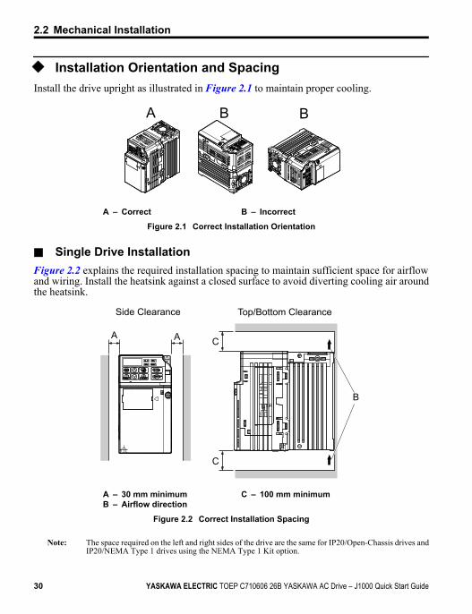
u Installation Orientation and SpacingInstall the drive upright as illustrated in Figure 2.1 to maintain proper cooling.
A B B
A – Correct B – Incorrect
Figure 2.1 Correct Installation Orientation
n Single Drive InstallationFigure 2.2 explains the required installation spacing to maintain sufficient space for airflowand wiring. Install the heatsink against a closed surface to avoid diverting cooling air aroundthe heatsink.
A A C
C
B
Side Clearance Top/Bottom Clearance
A – 30 mm minimumB – Airflow direction
C – 100 mm minimum
Figure 2.2 Correct Installation Spacing
Note: The space required on the left and right sides of the drive are the same for IP20/Open-Chassis drives andIP20/NEMA Type 1 drives using the NEMA Type 1 Kit option.
2.2 Mechanical Installation
30 YASKAWA ELECTRIC TOEP C710606 26B YASKAWA AC Drive – J1000 Quick Start Guide
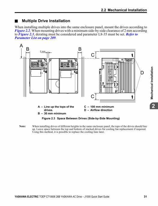
n Multiple Drive InstallationWhen installing multiple drives into the same enclosure panel, mount the drives according toFigure 2.2. When mounting drives with a minimum side-by-side clearance of 2 mm accordingto Figure 2.3, derating must be considered and parameter L8-35 must be set. Refer to Parameter List on page 209.
2 mm
D
C
CBB
A
A – Line up the tops of thedrives.
B – 30 mm minimum
C – 100 mm minimumD – Airflow direction
Figure 2.3 Space Between Drives (Side-by-Side Mounting)
Note: When installing drives of different heights in the same enclosure panel, the tops of the drives should lineup. Leave space between the top and bottom of stacked drives for cooling fan replacement if required.Using this method, it is possible to replace the cooling fans later.
2.2 Mechanical Installation
YASKAWA ELECTRIC TOEP C710606 26B YASKAWA AC Drive – J1000 Quick Start Guide 31
2
Mec
hani
cal I
nsta
llatio
n
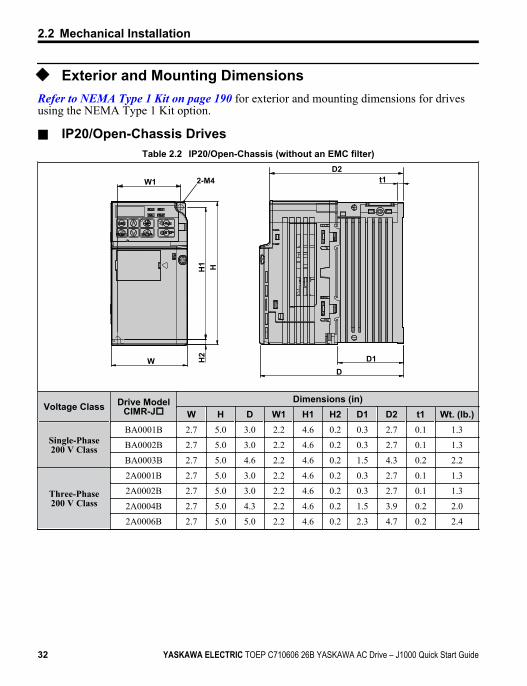
u Exterior and Mounting DimensionsRefer to NEMA Type 1 Kit on page 190 for exterior and mounting dimensions for drivesusing the NEMA Type 1 Kit option.
n IP20/Open-Chassis DrivesTable 2.2 IP20/Open-Chassis (without an EMC filter)
t1
D1D
W
H1
H2
H
2-M4W1D2
Voltage Class Drive ModelCIMR-Jo
Dimensions (in)W H D W1 H1 H2 D1 D2 t1 Wt. (lb.)
Single-Phase200 V Class
BA0001B 2.7 5.0 3.0 2.2 4.6 0.2 0.3 2.7 0.1 1.3
BA0002B 2.7 5.0 3.0 2.2 4.6 0.2 0.3 2.7 0.1 1.3
BA0003B 2.7 5.0 4.6 2.2 4.6 0.2 1.5 4.3 0.2 2.2
Three-Phase200 V Class
2A0001B 2.7 5.0 3.0 2.2 4.6 0.2 0.3 2.7 0.1 1.3
2A0002B 2.7 5.0 3.0 2.2 4.6 0.2 0.3 2.7 0.1 1.3
2A0004B 2.7 5.0 4.3 2.2 4.6 0.2 1.5 3.9 0.2 2.0
2A0006B 2.7 5.0 5.0 2.2 4.6 0.2 2.3 4.7 0.2 2.4
2.2 Mechanical Installation
32 YASKAWA ELECTRIC TOEP C710606 26B YASKAWA AC Drive – J1000 Quick Start Guide
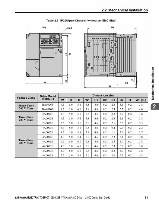
Table 2.3 IP20/Open-Chassis (without an EMC filter)
t1
DD1
4-M4
H
W1
W H2
H1
D2
Voltage Class Drive ModelCIMR-Jo
Dimensions (in)W H D W1 H1 H2 D1 D2 t1 Wt. (lb.)
Single-Phase200 V Class
BA0006B 4.3 5.0 5.4 3.8 4.6 0.2 2.3 5.1 0.2 3.8
BA0010B 4.3 5.0 6.1 3.8 4.6 0.2 2.3 5.7 0.2 4.0
Three-Phase200 V Class
2A0010B 4.3 5.0 5.1 3.8 4.6 0.2 2.3 4.7 0.2 3.8
2A0012B 4.3 5.0 5.4 3.8 4.6 0.2 2.3 5.1 0.2 3.8
2A0020B 5.5 5.0 5.6 5.0 4.6 0.2 2.6 5.3 0.2 5.3
Three-Phase400 V Class
4A0001B 4.3 5.0 3.2 3.8 4.6 0.2 0.4 2.9 0.2 2.2
4A0002B 4.3 5.0 3.9 3.8 4.6 0.2 1.1 3.6 0.2 2.7
4A0004B 4.3 5.0 5.4 3.8 4.6 0.2 2.3 5.1 0.2 3.8
4A0005B 4.3 5.0 6.1 3.8 4.6 0.2 2.3 5.7 0.2 3.8
4A0007B 4.3 5.0 6.1 3.8 4.6 0.2 2.3 5.7 0.2 3.8
4A0009B 4.3 5.0 6.1 3.8 4.6 0.2 2.3 5.7 0.2 3.8
4A0011B 5.5 5.0 5.6 5.0 4.6 0.2 2.6 5.3 0.2 5.3
2.2 Mechanical Installation
YASKAWA ELECTRIC TOEP C710606 26B YASKAWA AC Drive – J1000 Quick Start Guide 33
2
Mec
hani
cal I
nsta
llatio
n
2.2 Mechanical Installation
This Page Intentionally Blank
34 YASKAWA ELECTRIC TOEP C710606 26B YASKAWA AC Drive – J1000 Quick Start Guide
ElectricalInstallation
This chapter explains proper procedures for wiring the controlcircuit terminals, motor and power supply.
3.1 SECTION SAFETY.............................................363.2 STANDARD CONNECTION DIAGRAM...............393.3 MAIN CIRCUIT CONNECTION DIAGRAM..........423.4 TERMINAL BLOCK CONFIGURATION..............433.5 PROTECTIVE COVERS.....................................443.6 MAIN CIRCUIT WIRING.....................................463.7 CONTROL CIRCUIT WIRING.............................523.8 I/O CONNECTIONS...........................................593.9 MAIN FREQUENCY REFERENCE......................623.10 BRAKING RESISTOR........................................643.11 INTERLOCKING WITH CONNECTED
MACHINERY.....................................................663.12 WIRING CHECKLIST.........................................67
3
YASKAWA ELECTRIC TOEP C710606 26B YASKAWA AC Drive – J1000 Quick Start Guide 35

3.1 Section Safety
DANGER
Electrical Shock HazardDo not connect or disconnect wiring while the power is on.Failure to comply will result in death or serious injury.
WARNING
Electrical Shock HazardDo not operate equipment with covers removed.Failure to comply could result in death or serious injury.The diagrams in this section may show drives without covers or safety shields to showdetails. Be sure to reinstall covers or shields before operating the drives and run the drivesaccording to the instructions described in this manual.Always ground the motor-side grounding terminal.Improper equipment grounding could result in death or serious injury by contacting themotor case.Do not perform work on the drive while wearing loose clothing, jewelry or without eyeprotection.Failure to comply could result in death or serious injury.Remove all metal objects such as watches and rings, secure loose clothing, and wear eyeprotection before beginning work on the drive.Do not remove covers or touch circuit boards while the power is on.Failure to comply could result in death or serious injury.Do not allow unqualified personnel to perform work on the drive.Failure to comply could result in death or serious injury.Installation, maintenance, inspection, and servicing must be performed only by authorizedpersonnel familiar with installation, adjustment, and maintenance of AC drives.
3.1 Section Safety
36 YASKAWA ELECTRIC TOEP C710606 26B YASKAWA AC Drive – J1000 Quick Start Guide
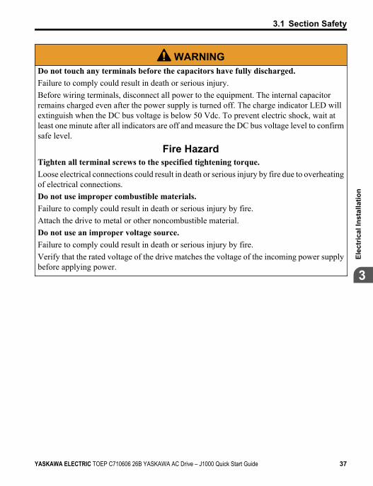
WARNINGDo not touch any terminals before the capacitors have fully discharged.Failure to comply could result in death or serious injury.Before wiring terminals, disconnect all power to the equipment. The internal capacitorremains charged even after the power supply is turned off. The charge indicator LED willextinguish when the DC bus voltage is below 50 Vdc. To prevent electric shock, wait atleast one minute after all indicators are off and measure the DC bus voltage level to confirmsafe level.
Fire HazardTighten all terminal screws to the specified tightening torque.Loose electrical connections could result in death or serious injury by fire due to overheatingof electrical connections.Do not use improper combustible materials.Failure to comply could result in death or serious injury by fire.Attach the drive to metal or other noncombustible material.Do not use an improper voltage source.Failure to comply could result in death or serious injury by fire.Verify that the rated voltage of the drive matches the voltage of the incoming power supplybefore applying power.
3.1 Section Safety
YASKAWA ELECTRIC TOEP C710606 26B YASKAWA AC Drive – J1000 Quick Start Guide 37
3
Elec
tric
al In
stal
latio
n
NOTICE
Observe proper electrostatic discharge procedures (ESD) when handling the drive andcircuit boards.Failure to comply may result in ESD damage to the drive circuitry.Never connect or disconnect the motor from the drive while the drive is outputtingvoltage.Improper equipment sequencing could result in damage to the drive.Do not use unshielded cable for control wiring.Failure to comply may cause electrical interference resulting in poor system performance.Use shielded, twisted-pair wires and ground the shield to the ground terminal of the drive.Check all the wiring to ensure that all connections are correct after installing the driveand connecting any other devices.Failure to comply could result in damage to the drive.Do not modify the drive circuitry.Failure to comply could result in damage to the drive and will void warranty.Yaskawa is not responsible for any modification of the product made by the user. Thisproduct must not be modified.
3.1 Section Safety
38 YASKAWA ELECTRIC TOEP C710606 26B YASKAWA AC Drive – J1000 Quick Start Guide
3.2 Standard Connection DiagramConnect the drive and peripheral devices as shown in Figure 3.. It is possible to run the drivevia the digital operator without connecting digital I/O wiring. This section does not discussdrive operation; Refer to Start-Up Programming & Operation on page 69 for instructionson operating the drive.NOTICE: Inadequate branch short circuit protection could result in damage to the drive. Install adequatebranch circuit short circuit protection per applicable codes. The drive is suitable for circuits capable ofdelivering not more than 31,000 RMS symmetrical amperes, 240 Vac maximum (200 V Class) and 480 Vacmaximum (400 V Class).
NOTICE: When the wiring distance is greater than 100 meters, pay special attention to the motor insulationvoltage or use a drive duty motor. Failure to comply could lead to motor insulation breakdown.
NOTICE: Do not connect AC control circuit ground to drive enclosure. Improper drive grounding can causecontrol circuit malfunction.
NOTICE: The minimum load for the multi-function relay output MA-MB-MC is 10 mA.
3.2 Standard Connection Diagram
YASKAWA ELECTRIC TOEP C710606 26B YASKAWA AC Drive – J1000 Quick Start Guide 39
3
Elec
tric
al In
stal
latio
n
SA
MotorCooling fan
Forward run/stop
Reverse run/stop
External fault
Fault reset
0 to +10 Vdc (2 mA)
DIPswitch S3
DC link choke(option)
Digital inputs(default setting)
Fault
J1000
Shield groundterminal
Thermal relay(option) Braking resistor
(option)
Main circuit
Control circuit
Thermal relay formotor cooling fan
Fault relay
1 MCCB MC
2 MCCBr1s1
t1
R/L1
S/L2
T/L3
S1
S2
S3
S4
S5
<3><1> <2>
- B1+1+2 B2
R/L1S/L2
T/L3
MCTHRX
TRX
MCTRX
MC MA
U/T1
V/T2
W/T3
24
V
MA
MB
MC
I V
+24 V 8 mA
M
M
r1
s1
t1
FU
FVFW
U
V
W
SC
AM
AC
+
-
AM
+V
A1
AC
2 k
Ground10 or less (400 V class)100 or less (200 V class)
Setting power supply+10.5 max. 20 mA
For single phase 200 Vpower supply, useR/L1 and S/L2.
Analog monitoroutput
Digital output250 Vac, 10 mA to 1 A30 Vdc, 10 mA to 1 A(default setting)
Main speedfrequencyreference.Multi-functionprogrammable
Multi-step speed 1 main/aux switch
2 MCCB THRX OFF ON MC
SA
SA
Three phasepower supply
for 200 V /400 V
Jumper
DIP switch S1
Sink
Source
Terminals +1, +2, , B1, and B2are for connecting options.Never connect power supplylines to these terminals.
_
Monitoroutput
Option unitconnector
main circuit terminal
shielded line twisted-pair shielded line
control terminal
<4>
<5>
<6>
<7>0 to +10 V (20 k )(0)4 to 20 mA (250 )
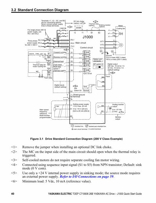
Figure 3.1 Drive Standard Connection Diagram (200 V Class Example)
<1> Remove the jumper when installing an optional DC link choke.<2> The MC on the input side of the main circuit should open when the thermal relay is
triggered.<3> Self-cooled motors do not require separate cooling fan motor wiring.<4> Connected using sequence input signal (S1 to S5) from NPN transistor; Default: sink
mode (0 V com).<5> Use only a +24 V internal power supply in sinking mode; the source mode requires
an external power supply. Refer to I/O Connections on page 59.<6> Minimum load: 5 Vdc, 10 mA (reference value).
3.2 Standard Connection Diagram
40 YASKAWA ELECTRIC TOEP C710606 26B YASKAWA AC Drive – J1000 Quick Start Guide
<7> Monitor outputs work with devices such as analog frequency meters, ammeters,voltmeters and wattmeters; they are not intended for use as a feedback-type of signal.
WARNING! Sudden Movement Hazard. Do not close the wiring for the control circuit unless the multifunctioninput terminal parameter is properly set (S5 for 3-Wire; H1-05 = “0”). Improper sequencing of run/stop circuitrycould result in death or serious injury from moving equipment.
WARNING! Sudden Movement Hazard. Ensure start/stop and safety circuits are wired properly and in thecorrect state before energizing the drive. Failure to comply could result in death or serious injury from movingequipment. When programmed for 3-Wire control, a momentary closure on terminal S1 may cause the driveto start.
WARNING! When 3-Wire sequence is used, set the drive to 3-Wire sequence before wiring the controlterminals and ensure parameter b1-17 is set to 0 (drive does not accept a run command at power up (default).If the drive is wired for 3-Wire sequence but set up for 2-Wire sequence (default) and if parameter b1-17 isset to 1 (drive accepts a Run command at power up), the motor will rotate in reverse direction at power up ofthe drive and may cause injury.
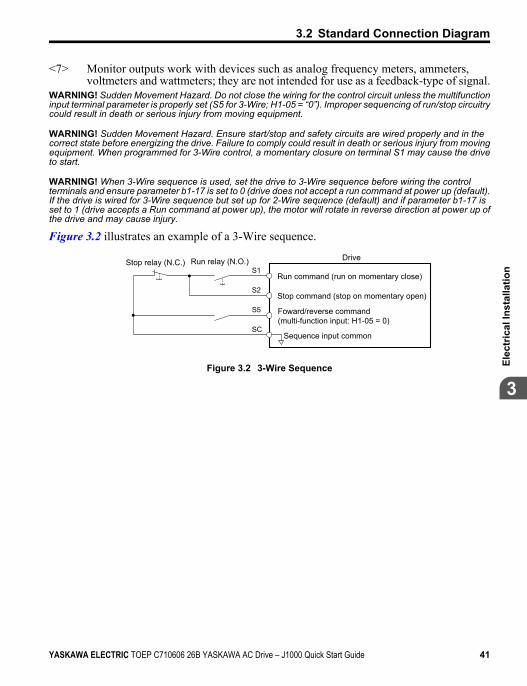
Figure 3.2 illustrates an example of a 3-Wire sequence.
Drive
Sequence input common
Run relay (N.O.)Stop relay (N.C.)
Run command (run on momentary close)
Stop command (stop on momentary open)
Foward/reverse command (multi-function input: H1-05 = 0)
S1
S2
S5
SC
Figure 3.2 3-Wire Sequence
3.2 Standard Connection Diagram
YASKAWA ELECTRIC TOEP C710606 26B YASKAWA AC Drive – J1000 Quick Start Guide 41
3
Elec
tric
al In
stal
latio
n
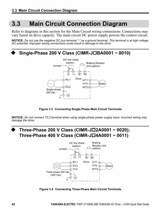
3.3 Main Circuit Connection DiagramRefer to diagrams in this section for the Main Circuit wiring connections. Connections mayvary based on drive capacity. The main circuit DC power supply powers the control circuit.NOTICE: Do not use the negative DC bus terminal “-” as a ground terminal. This terminal is at high voltageDC potential. Improper wiring connections could result in damage to the drive.
u Single-Phase 200 V Class (CIMR-JoBA0001 ~ 0010)
Drive
Jumper
Single-phase 200 Vac
Motor
DC link choke(option) Braking Resistor
Unit (option)
R/L1
S/L2
+1+2
–
B1 B2
U/T1V/T2W/T3
Figure 3.3 Connecting Single-Phase Main Circuit Terminals
NOTICE: Do not connect T/L3 terminal when using single-phase power supply input. Incorrect wiring maydamage the drive.
u Three-Phase 200 V Class (CIMR-Jo2A0001 ~ 0020);Three-Phase 400 V Class (CIMR-Jo4A0001 ~ 0011)
—
Drive
Motor
Three phase 200 Vac (400 Vac)
Braking Resistor Unit(option)
R/L1S/L2T/L3
U/T1V/T2W/T3
B1 B2
Jumper
DC link choke(option)
+1+2
Figure 3.4 Connecting Three-Phase Main Circuit Terminals
3.3 Main Circuit Connection Diagram
42 YASKAWA ELECTRIC TOEP C710606 26B YASKAWA AC Drive – J1000 Quick Start Guide
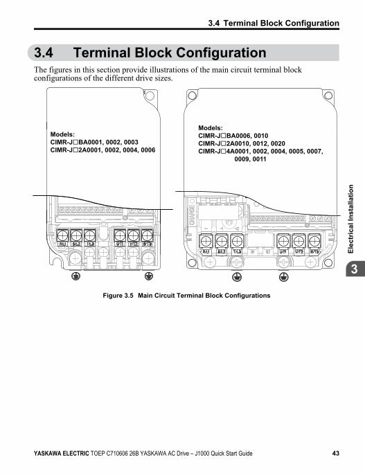
3.4 Terminal Block ConfigurationThe figures in this section provide illustrations of the main circuit terminal blockconfigurations of the different drive sizes.
Models:CIMR-JBA0006, 0010CIMR-J2A0010, 0012, 0020CIMR-J4A0001, 0002, 0004, 0005, 0007, 0009, 0011
Models:CIMR-JBA0001, 0002, 0003CIMR-J2A0001, 0002, 0004, 0006
Figure 3.5 Main Circuit Terminal Block Configurations
3.4 Terminal Block Configuration
YASKAWA ELECTRIC TOEP C710606 26B YASKAWA AC Drive – J1000 Quick Start Guide 43
3
Elec
tric
al In
stal
latio
n
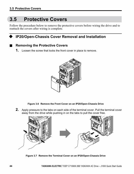
3.5 Protective CoversFollow the procedure below to remove the protective covers before wiring the drive and toreattach the covers after wiring is complete.
u IP20/Open-Chassis Cover Removal and Installation
n Removing the Protective Covers1. Loosen the screw that locks the front cover in place to remove.
Figure 3.6 Remove the Front Cover on an IP20/Open-Chassis Drive
2. Apply pressure to the tabs on each side of the terminal cover. Pull the terminal coveraway from the drive while pushing in on the tabs to pull the cover free.
Figure 3.7 Remove the Terminal Cover on an IP20/Open-Chassis Drive
3.5 Protective Covers
44 YASKAWA ELECTRIC TOEP C710606 26B YASKAWA AC Drive – J1000 Quick Start Guide
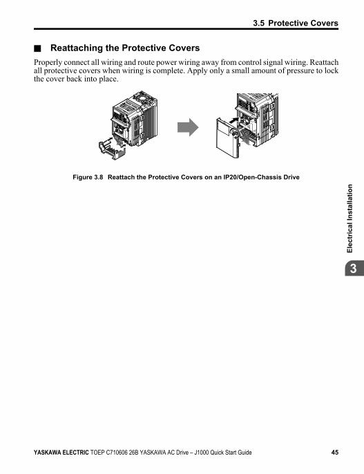
n Reattaching the Protective CoversProperly connect all wiring and route power wiring away from control signal wiring. Reattachall protective covers when wiring is complete. Apply only a small amount of pressure to lockthe cover back into place.
Figure 3.8 Reattach the Protective Covers on an IP20/Open-Chassis Drive
3.5 Protective Covers
YASKAWA ELECTRIC TOEP C710606 26B YASKAWA AC Drive – J1000 Quick Start Guide 45
3
Elec
tric
al In
stal
latio
n
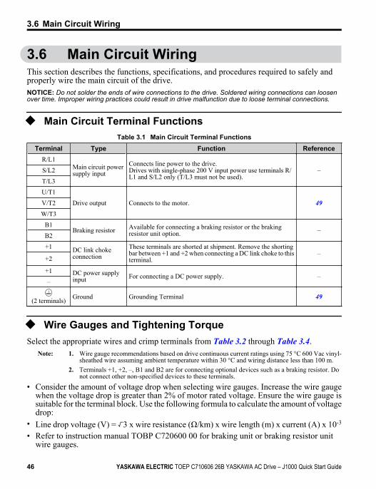
3.6 Main Circuit WiringThis section describes the functions, specifications, and procedures required to safely andproperly wire the main circuit of the drive.NOTICE: Do not solder the ends of wire connections to the drive. Soldered wiring connections can loosenover time. Improper wiring practices could result in drive malfunction due to loose terminal connections.
u Main Circuit Terminal FunctionsTable 3.1 Main Circuit Terminal Functions
Terminal Type Function ReferenceR/L1
Main circuit powersupply input
Connects line power to the drive.Drives with single-phase 200 V input power use terminals R/L1 and S/L2 only (T/L3 must not be used).
–S/L2
T/L3
U/T1
Drive output Connects to the motor. 49V/T2
W/T3
B1Braking resistor Available for connecting a braking resistor or the braking
resistor unit option. –B2
+1 DC link chokeconnection
These terminals are shorted at shipment. Remove the shortingbar between +1 and +2 when connecting a DC link choke to thisterminal.
–+2
+1 DC power supplyinput For connecting a DC power supply. –
–
(2 terminals) Ground Grounding Terminal 49
u Wire Gauges and Tightening TorqueSelect the appropriate wires and crimp terminals from Table 3.2 through Table 3.4.
Note: 1. Wire gauge recommendations based on drive continuous current ratings using 75 °C 600 Vac vinyl-sheathed wire assuming ambient temperature within 30 °C and wiring distance less than 100 m.
2. Terminals +1, +2, –, B1 and B2 are for connecting optional devices such as a braking resistor. Donot connect other non-specified devices to these terminals.
• Consider the amount of voltage drop when selecting wire gauges. Increase the wire gaugewhen the voltage drop is greater than 2% of motor rated voltage. Ensure the wire gauge issuitable for the terminal block. Use the following formula to calculate the amount of voltagedrop:
• Line drop voltage (V) = 3 x wire resistance (Ω/km) x wire length (m) x current (A) x 10-3
• Refer to instruction manual TOBP C720600 00 for braking unit or braking resistor unitwire gauges.
3.6 Main Circuit Wiring
46 YASKAWA ELECTRIC TOEP C710606 26B YASKAWA AC Drive – J1000 Quick Start Guide
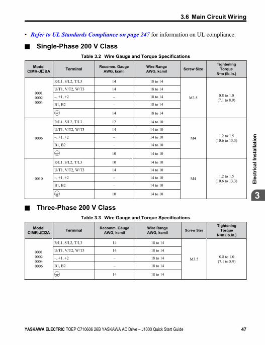
• Refer to UL Standards Compliance on page 247 for information on UL compliance.
n Single-Phase 200 V ClassTable 3.2 Wire Gauge and Torque Specifications
ModelCIMR-JoBA Terminal Recomm. Gauge
AWG, kcmilWire RangeAWG, kcmil Screw Size
TighteningTorque
N•m (lb.in.)
000100020003
R/L1, S/L2, T/L3 14 18 to 14
M3.5 0.8 to 1.0(7.1 to 8.9)
U/T1, V/T2, W/T3 14 18 to 14
–, +1, +2 – 18 to 14
B1, B2 – 18 to 14
14 18 to 14
0006
R/L1, S/L2, T/L3 12 14 to 10
M4 1.2 to 1.5(10.6 to 13.3)
U/T1, V/T2, W/T3 14 14 to 10
–, +1, +2 – 14 to 10
B1, B2 – 14 to 10
10 14 to 10
0010
R/L1, S/L2, T/L3 10 14 to 10
M4 1.2 to 1.5(10.6 to 13.3)
U/T1, V/T2, W/T3 14 14 to 10
–, +1, +2 – 14 to 10
B1, B2 – 14 to 10
10 14 to 10
n Three-Phase 200 V ClassTable 3.3 Wire Gauge and Torque Specifications
ModelCIMR-Jo2A Terminal Recomm. Gauge
AWG, kcmilWire RangeAWG, kcmil Screw Size
TighteningTorque
N•m (lb.in.)
0001000200040006
R/L1, S/L2, T/L3 14 18 to 14
M3.5 0.8 to 1.0(7.1 to 8.9)
U/T1, V/T2, W/T3 14 18 to 14
–, +1, +2 – 18 to 14
B1, B2 – 18 to 14
14 18 to 14
3.6 Main Circuit Wiring
YASKAWA ELECTRIC TOEP C710606 26B YASKAWA AC Drive – J1000 Quick Start Guide 47
3
Elec
tric
al In
stal
latio
n
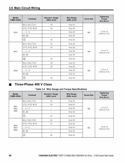
ModelCIMR-Jo2A Terminal Recomm. Gauge
AWG, kcmilWire RangeAWG, kcmil Screw Size
TighteningTorque
N•m (lb.in.)
0010
R/L1, S/L2, T/L3 14 14 to 10
M4 1.2 to 1.5(10.6 to 13.3)
U/T1, V/T2, W/T3 14 14 to 10
–, +1, +2 – 14 to 10
B1, B2 – 14 to 10
10 14 to 10
0012
R/L1, S/L2, T/L3 12 14 to 10
M4 1.2 to 1.5(10.6 to 13.3)
U/T1, V/T2, W/T3 14 14 to 10
–, +1, +2 – 14 to 10
B1, B2 – 14 to 10
10 14 to 10
0020
R/L1, S/L2, T/L3 10 14 to 10
M4 1.2 to 1.5(10.6 to 13.3)
U/T1, V/T2, W/T3 10 14 to 10
–, +1, +2 – 14 to 10
B1, B2 – 14 to 10
10 14 to 10
n Three-Phase 400 V ClassTable 3.4 Wire Gauge and Torque Specifications
ModelCIMR-Jo4A Terminal Recomm. Gauge
AWG, kcmilWire RangeAWG, kcmil Screw Size
TighteningTorque
N•m (lb.in.)
000100020004
R/L1, S/L2, T/L3 14 14 to 10
M4 1.2 to 1.5(10.6 to 13.3)
U/T1, V/T2, W/T3 14 14 to 10
–, +1, +2 – 14 to 10
B1, B2 – 14 to 10
14 14 to 10
000500070009
R/L1, S/L2, T/L3 14 14 to 10
M4 1.2 to 1.5(10.6 to 13.3)
U/T1, V/T2, W/T3 14 14 to 10
–, +1, +2 – 14 to 10
B1, B2 – 14 to 10
10 14 to 10
3.6 Main Circuit Wiring
48 YASKAWA ELECTRIC TOEP C710606 26B YASKAWA AC Drive – J1000 Quick Start Guide
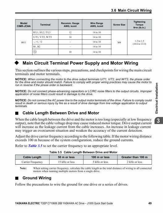
ModelCIMR-Jo4A Terminal Recomm. Gauge
AWG, kcmilWire RangeAWG, kcmil Screw Size
TighteningTorque
N•m (lb.in.)
0011
R/L1, S/L2, T/L3 12 14 to 10
M4 1.2 to 1.5(10.6 to 13.3)
U/T1, V/T2, W/T3 14 14 to 10
–, +1, +2 – 14 to 10
B1, B2 – 14 to 10
10 14 to 10
u Main Circuit Terminal Power Supply and Motor WiringThis section outlines the various steps, precautions, and checkpoints for wiring the main circuitterminals and motor terminals.NOTICE: When connecting the motor to the drive output terminals U/T1, V/T2, and W/T3, the phase orderfor the drive and motor should match. Failure to comply with proper wiring practices may cause the motor torun in reverse if the phase order is backward.
NOTICE: Do not connect phase-advancing capacitors or LC/RC noise filters to the output circuits. Improperapplication of noise filters could result in damage to the drive.
NOTICE: Do not connect the AC power line to the output motor terminals of the drive. Failure to comply couldresult in death or serious injury by fire as a result of drive damage from line voltage application to outputterminals.
n Cable Length Between Drive and MotorWhen the cable length between the drive and the motor is too long (especially at low frequencyoutput), note that the cable voltage drop may cause reduced motor torque. Drive output currentwill increase as the leakage current from the cable increases. An increase in leakage currentmay trigger an overcurrent situation and weaken the accuracy of the current detection.Adjust the drive carrier frequency according to the following table. If the motor wiring distanceexceeds 100 m because of the system configuration, reduce the ground currents.Refer to Table 3.5 to set the carrier frequency to an appropriate level.
Table 3.5 Cable Length Between Drive and MotorCable Length 50 m or less 100 m or less Greater than 100 m
Carrier Frequency 15 kHz or less 5 kHz or less 2 kHz or less
Note: When setting carrier frequency, calculate the cable length as the total distance of wiring to all connectedmotors when running multiple motors from a single drive.
n Ground WiringFollow the precautions to wire the ground for one drive or a series of drives.
3.6 Main Circuit Wiring
YASKAWA ELECTRIC TOEP C710606 26B YASKAWA AC Drive – J1000 Quick Start Guide 49
3
Elec
tric
al In
stal
latio
n
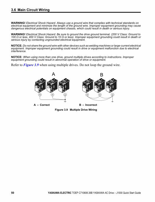
WARNING! Electrical Shock Hazard. Always use a ground wire that complies with technical standards onelectrical equipment and minimize the length of the ground wire. Improper equipment grounding may causedangerous electrical potentials on equipment chassis, which could result in death or serious injury.
WARNING! Electrical Shock Hazard. Be sure to ground the drive ground terminal. (200 V Class: Ground to100 Ω or less, 400 V Class: Ground to 10 Ω or less). Improper equipment grounding could result in death orserious injury by contacting ungrounded electrical equipment.
NOTICE: Do not share the ground wire with other devices such as welding machines or large-current electricalequipment. Improper equipment grounding could result in drive or equipment malfunction due to electricalinterference.
NOTICE: When using more than one drive, ground multiple drives according to instructions. Improperequipment grounding could result in abnormal operation of drive or equipment.
Refer to Figure 3.9 when using multiple drives. Do not loop the ground wire.
A B
A – Correct B – Incorrect
Figure 3.9 Multiple Drive Wiring
3.6 Main Circuit Wiring
50 YASKAWA ELECTRIC TOEP C710606 26B YASKAWA AC Drive – J1000 Quick Start Guide
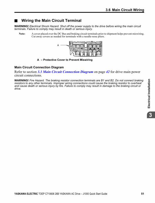
n Wiring the Main Circuit TerminalWARNING! Electrical Shock Hazard. Shut off the power supply to the drive before wiring the main circuitterminals. Failure to comply may result in death or serious injury.
Note: A cover placed over the DC Bus and braking circuit terminals prior to shipment helps prevent miswiring.Cut away covers as needed for terminals with a needle-nose pliers.
A
A – Protective Cover to Prevent Miswiring
Main Circuit Connection DiagramRefer to section 3.3 Main Circuit Connection Diagram on page 42 for drive main powercircuit connections.WARNING! Fire Hazard. The braking resistor connection terminals are B1 and B2. Do not connect brakingresistors to any other terminals. Improper wiring connections could cause the braking resistor to overheatand cause death or serious injury by fire. Failure to comply may result in damage to the braking circuit ordrive.
3.6 Main Circuit Wiring
YASKAWA ELECTRIC TOEP C710606 26B YASKAWA AC Drive – J1000 Quick Start Guide 51
3
Elec
tric
al In
stal
latio
n
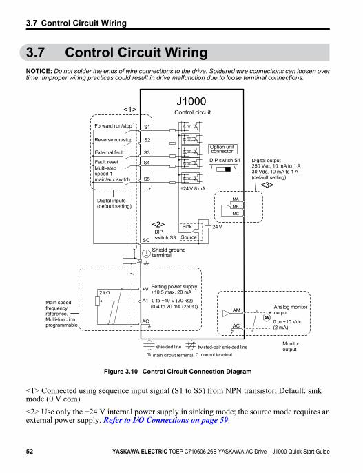
3.7 Control Circuit WiringNOTICE: Do not solder the ends of wire connections to the drive. Soldered wire connections can loosen overtime. Improper wiring practices could result in drive malfunction due to loose terminal connections.
S1
S2
S3
S4
S5
24 V
I V
+24 V 8 mA
SC
AM
AC
+
-
AM
+V
A1
AC
2 k
MA
MB
MC
Forward run/stop
Reverse run/stop
External fault
Fault reset
Digital inputs(default setting)
J1000Control circuit
Multi-step speed 1 main/aux switch
DIP switch S1
Option unitconnector
<1>
DIPswitch S3
Shield groundterminal
0 to +10 V (20 k )(0)4 to 20 mA (250 )
Setting power supply+10.5 max. 20 mA
Digital output250 Vac, 10 mA to 1 A30 Vdc, 10 mA to 1 A(default setting)
Main speedfrequencyreference.Multi-functionprogrammable
Sink
Source
<2>
<3>
0 to +10 Vdc (2 mA)
Analog monitoroutput
Monitoroutput
main circuit terminal
shielded line twisted-pair shielded line
control terminal
Figure 3.10 Control Circuit Connection Diagram
<1> Connected using sequence input signal (S1 to S5) from NPN transistor; Default: sinkmode (0 V com)<2> Use only the +24 V internal power supply in sinking mode; the source mode requires anexternal power supply. Refer to I/O Connections on page 59.
3.7 Control Circuit Wiring
52 YASKAWA ELECTRIC TOEP C710606 26B YASKAWA AC Drive – J1000 Quick Start Guide
<3> Minimum load: 5 Vdc, 10 mA (reference value).
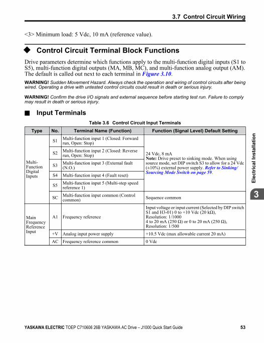
u Control Circuit Terminal Block FunctionsDrive parameters determine which functions apply to the multi-function digital inputs (S1 toS5), multi-function digital outputs (MA, MB, MC), and multi-function analog output (AM).The default is called out next to each terminal in Figure 3.10.WARNING! Sudden Movement Hazard. Always check the operation and wiring of control circuits after beingwired. Operating a drive with untested control circuits could result in death or serious injury.
WARNING! Confirm the drive I/O signals and external sequence before starting test run. Failure to complymay result in death or serious injury.
n Input TerminalsTable 3.6 Control Circuit Input Terminals
Type No. Terminal Name (Function) Function (Signal Level) Default Setting
Multi-FunctionDigitalInputs
S1 Multi-function input 1 (Closed: Forwardrun, Open: Stop)
24 Vdc, 8 mANote: Drive preset to sinking mode. When usingsource mode, set DIP switch S3 to allow for a 24 Vdc(±10%) external power supply. Refer to Sinking/Sourcing Mode Switch on page 59.
S2 Multi-function input 2 (Closed: Reverserun, Open: Stop)
S3 Multi-function input 3 (External fault(N.O.)
S4 Multi-function input 4 (Fault reset)
S5 Multi-function input 5 (Multi-step speedreference 1)
SC Multi-function input common (Controlcommon) Sequence common
MainFrequencyReferenceInput
A1 Frequency reference
Input voltage or input current (Selected by DIP switchS1 and H3-01) 0 to +10 Vdc (20 kΩ),Resolution: 1/10004 to 20 mA (250 Ω) or 0 to 20 mA (250 Ω),Resolution: 1/500
+V Analog input power supply +10.5 Vdc (max allowable current 20 mA)
AC Frequency reference common 0 Vdc
3.7 Control Circuit Wiring
YASKAWA ELECTRIC TOEP C710606 26B YASKAWA AC Drive – J1000 Quick Start Guide 53
3
Elec
tric
al In
stal
latio
n
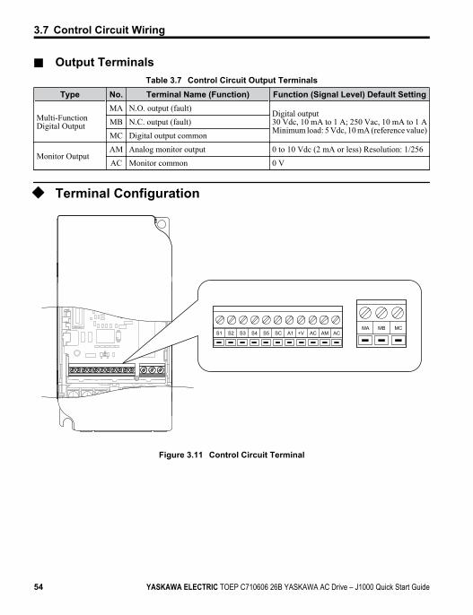
n Output TerminalsTable 3.7 Control Circuit Output Terminals
Type No. Terminal Name (Function) Function (Signal Level) Default Setting
Multi-FunctionDigital Output
MA N.O. output (fault) Digital output30 Vdc, 10 mA to 1 A; 250 Vac, 10 mA to 1 AMinimum load: 5 Vdc, 10 mA (reference value)
MB N.C. output (fault)
MC Digital output common
Monitor OutputAM Analog monitor output 0 to 10 Vdc (2 mA or less) Resolution: 1/256
AC Monitor common 0 V
u Terminal Configuration
S1 S2 S3 S4 S5 SC A1 +V AC AM ACMCMBMA
Figure 3.11 Control Circuit Terminal
3.7 Control Circuit Wiring
54 YASKAWA ELECTRIC TOEP C710606 26B YASKAWA AC Drive – J1000 Quick Start Guide
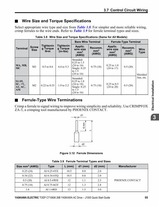
n Wire Size and Torque SpecificationsSelect appropriate wire type and size from Table 3.8. For simpler and more reliable wiring,crimp ferrules to the wire ends. Refer to Table 3.9 for ferrule terminal types and sizes.
Table 3.8 Wire Size and Torque Specifications (Same for All Models)
Terminal ScrewSize
Tightening Torque
N•m
Tightening Torque(in-lbs)
Bare Wire Terminal Ferrule-Type TerminalApplic.
wire sizemm2
(AWG)
Recomm.mm2
(AWG)
Applic.wire size
mm2
(AWG)
Recomm.mm2
(AWG)WireType
MA, MB,MC M3 0.5 to 0.6 4.4 to 5.3
Stranded:0.25 to 1.5(24 to 16)Single: 0.25to 1.5(24 to 16)
0.75 (18) 0.25 to 1.0(24 to 17) 0.5 (20)
Shieldedline, etc.
S1-S5,SC, +V,A1, AC,AM
M2 0.22 to 0.25 1.9 to 2.2
Stranded:0.25 to 1.0(24 to 18)Single: 0.25to 1.5(24 to 16)
0.75 (18) 0.25 to 0.5(24 to 20) 0.5 (20)
n Ferrule-Type Wire TerminationsCrimp a ferrule to signal wiring to improve wiring simplicity and reliability. Use CRIMPFOXZA-3, a crimping tool manufactured by PHOENIX CONTACT.
d1
d2
6 m
m
L
Figure 3.12 Ferrule Dimensions
Table 3.9 Ferrule Terminal Types and Sizes
Size mm2 (AWG) Type L (mm) d1 (mm) d2 (mm) Manufacturer0.25 (24) AI 0.25-6YE 10.5 0.8 2.0
PHOENIX CONTACT
0.34 (22) AI 0.34-6TQ 10.5 0.8 2.0
0.5 (20) AI 0.5-6WH 12 1.1 2.5
0.75 (18) AI 0.75-6GY 12 1.3 2.8
1.0 AI 1-6RD 12 1.5 3.0
3.7 Control Circuit Wiring
YASKAWA ELECTRIC TOEP C710606 26B YASKAWA AC Drive – J1000 Quick Start Guide 55
3
Elec
tric
al In
stal
latio
n
u Wiring ProcedureThis section describes the proper procedures and preparations for wiring the control terminals.WARNING! Electrical Shock Hazard. Do not remove covers or touch the circuit boards while the power is on.Failure to comply could result in death or serious injury.
NOTICE: Separate control circuit wiring from main circuit wiring (terminals R/L1, S/L2, T/L3, B1, B2, U/T1,V/T2, W/T3, -, +1, +2) and other high-power lines. Improper wiring practices could result in drive malfunctiondue to electrical interference.
NOTICE: Separate wiring for digital output terminals MA, MB and MC from wiring to other control circuit lines.Improper wiring practices could result in drive or equipment malfunction or nuisance trips.
NOTICE: Use a class 2 power supply (UL standard) when connecting to the control terminals. Improperapplication of peripheral devices could result in drive performance degradation due to improper power supply.
NOTICE: Insulate shields with tape or shrink tubing to prevent contact with other signal lines and equipment.Improper wiring practices could result in drive or equipment malfunction due to short circuit.
NOTICE: Connect the shield of shielded cable to the appropriate ground terminal. Improper equipmentgrounding could result in drive or equipment malfunction or nuisance trips.
Wire the control terminals using Figure 3.13 as a guide. Prepare the ends of the control circuitwiring as shown in Figure 3.14. Refer to Wire Size and Torque Specifications on page 55.NOTICE: Do not tighten screws beyond the specified tightening torque. Failure to comply may damage theterminal.
NOTICE: Use shielded twisted-pair cables as indicated to prevent operating faults. Improper wiring practicescould result in drive or equipment malfunction due to electrical interference.
Connect control wires as shown in the following figure:
3.7 Control Circuit Wiring
56 YASKAWA ELECTRIC TOEP C710606 26B YASKAWA AC Drive – J1000 Quick Start Guide
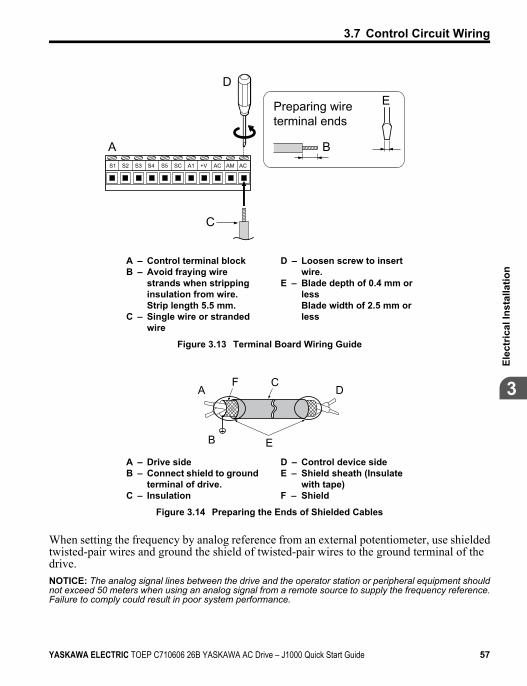
S1 S2 S3 S4 S5 SC A1 +V AC AM AC
A
D
C
E
B
Preparing wireterminal ends
A – Control terminal blockB – Avoid fraying wire
strands when strippinginsulation from wire.Strip length 5.5 mm.
C – Single wire or strandedwire
D – Loosen screw to insertwire.
E – Blade depth of 0.4 mm orlessBlade width of 2.5 mm orless
Figure 3.13 Terminal Board Wiring Guide
AF C
D
EB
A – Drive sideB – Connect shield to ground
terminal of drive.C – Insulation
D – Control device sideE – Shield sheath (Insulate
with tape)F – Shield
Figure 3.14 Preparing the Ends of Shielded Cables
When setting the frequency by analog reference from an external potentiometer, use shieldedtwisted-pair wires and ground the shield of twisted-pair wires to the ground terminal of thedrive.NOTICE: The analog signal lines between the drive and the operator station or peripheral equipment shouldnot exceed 50 meters when using an analog signal from a remote source to supply the frequency reference.Failure to comply could result in poor system performance.
3.7 Control Circuit Wiring
YASKAWA ELECTRIC TOEP C710606 26B YASKAWA AC Drive – J1000 Quick Start Guide 57
3
Elec
tric
al In
stal
latio
n
+V
A1
AC
A
B
CD
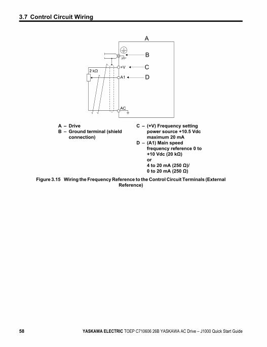
A – DriveB – Ground terminal (shield
connection)
C – (+V) Frequency settingpower source +10.5 Vdcmaximum 20 mA
D – (A1) Main speedfrequency reference 0 to+10 Vdc (20 kΩ)or4 to 20 mA (250 Ω)/0 to 20 mA (250 Ω)
Figure 3.15 Wiring the Frequency Reference to the Control Circuit Terminals (ExternalReference)
3.7 Control Circuit Wiring
58 YASKAWA ELECTRIC TOEP C710606 26B YASKAWA AC Drive – J1000 Quick Start Guide
3.8 I/O Connections
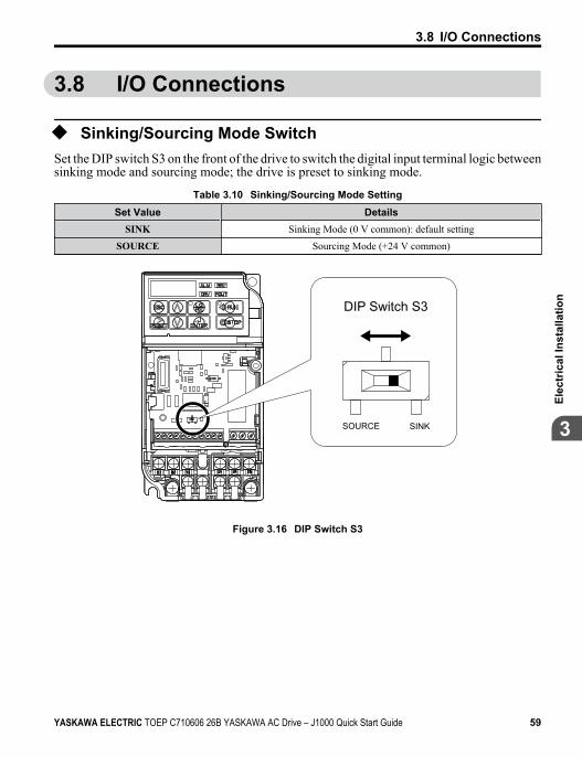
u Sinking/Sourcing Mode SwitchSet the DIP switch S3 on the front of the drive to switch the digital input terminal logic betweensinking mode and sourcing mode; the drive is preset to sinking mode.
Table 3.10 Sinking/Sourcing Mode SettingSet Value Details
SINK Sinking Mode (0 V common): default setting
SOURCE Sourcing Mode (+24 V common)
SINKSOURCE
DIP Switch S3
Figure 3.16 DIP Switch S3
3.8 I/O Connections
YASKAWA ELECTRIC TOEP C710606 26B YASKAWA AC Drive – J1000 Quick Start Guide 59
3
Elec
tric
al In
stal
latio
n
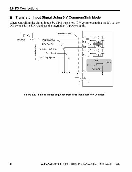
n Transistor Input Signal Using 0 V Common/Sink ModeWhen controlling the digital inputs by NPN transistors (0 V common/sinking mode), set theDIP switch S3 to SINK and use the internal 24 V power supply.
S1SINKSOURCE
S2
S3
S3+24 V
S4
S5
SC
SINK
SOURCE
FWD Run/Stop
REV Run/Stop
External Fault N.O.
Fault Reset
Multi-step Speed 1
Shielded CableM
ulti-
func
iton
inpu
t
Figure 3.17 Sinking Mode: Sequence from NPN Transistor (0 V Common)
3.8 I/O Connections
60 YASKAWA ELECTRIC TOEP C710606 26B YASKAWA AC Drive – J1000 Quick Start Guide
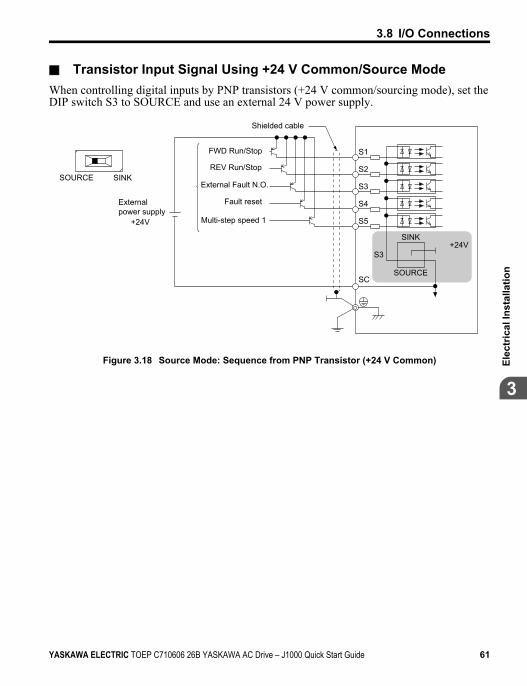
n Transistor Input Signal Using +24 V Common/Source ModeWhen controlling digital inputs by PNP transistors (+24 V common/sourcing mode), set theDIP switch S3 to SOURCE and use an external 24 V power supply.
S1
+24V
S2
S3
+24V
S4
S5
SC
S3
SINKSOURCE
SINK
SOURCE
Externalpower supply
FWD Run/Stop
REV Run/Stop
External Fault N.O.
Fault reset
Multi-step speed 1
Shielded cable
Figure 3.18 Source Mode: Sequence from PNP Transistor (+24 V Common)
3.8 I/O Connections
YASKAWA ELECTRIC TOEP C710606 26B YASKAWA AC Drive – J1000 Quick Start Guide 61
3
Elec
tric
al In
stal
latio
n
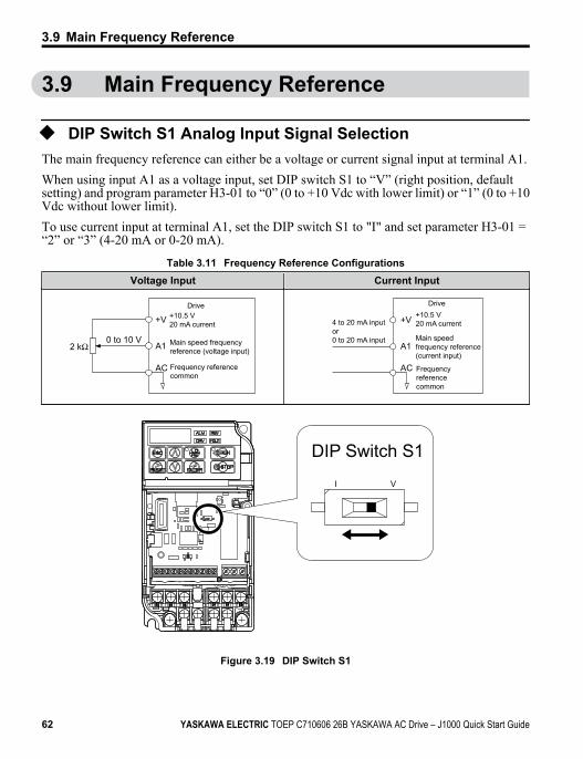
3.9 Main Frequency Reference
u DIP Switch S1 Analog Input Signal SelectionThe main frequency reference can either be a voltage or current signal input at terminal A1.When using input A1 as a voltage input, set DIP switch S1 to “V” (right position, defaultsetting) and program parameter H3-01 to “0” (0 to +10 Vdc with lower limit) or “1” (0 to +10Vdc without lower limit).To use current input at terminal A1, set the DIP switch S1 to "I" and set parameter H3-01 =“2” or “3” (4-20 mA or 0-20 mA).
Table 3.11 Frequency Reference ConfigurationsVoltage Input Current Input
+10.5 V20 mA current
Main speed frequency reference (voltage input)
Frequency referencecommon
Drive
+V
A1
AC
0 to 10 V
+10.5 V20 mA current
Main speedfrequency reference(current input)
Frequency referencecommon
+V
A1
AC
Drive
4 to 20 mA inputor0 to 20 mA input
I V
DIP Switch S1
Figure 3.19 DIP Switch S1
3.9 Main Frequency Reference
62 YASKAWA ELECTRIC TOEP C710606 26B YASKAWA AC Drive – J1000 Quick Start Guide
Table 3.12 DIP Switch S1 SettingsSetting Value Description
V ( right position) Voltage input (0 to 10 V): default setting
I ( left position) Current input (4 to 20 mA or 0 to 20 mA)
Table 3.13 Parameter H3-01 Details
No. Parameter Name Description SettingRange
DefaultSetting
MEMOBUSRegister
H3-01Frequency ref.(voltage/current)terminal A1 signallevel selection
Selects the signal level for terminal A1.0: 0 to +10 V, unipolar input (negativefrequency reference values are zeroed)1: 0 to +10 V, bipolar input (negativefrequency reference changes the direction)2: 4 to 20 mA3: 0 to 20 mA
0 to 3 0 410
3.9 Main Frequency Reference
YASKAWA ELECTRIC TOEP C710606 26B YASKAWA AC Drive – J1000 Quick Start Guide 63
3
Elec
tric
al In
stal
latio
n
3.10 Braking ResistorDynamic braking (DB) helps bring the motor to a smooth and rapid stop when working withhigh inertia loads. Regeneration occurs as the drive lowers the motor frequency with highinertia. When the regeneration flows back into the DC bus capacitors, an overvoltage situationoccurs. A braking resistor prevents these overvoltage faults.NOTICE: Do not allow unqualified personnel to use the product. Failure to comply could result in damage tothe drive or braking circuit. Carefully review the braking resistor instruction manual when connecting a brakingoption to the drive.
Note: The braking circuit must be sized properly in order to dissipate the power required to decelerate the loadin the desired time. Ensure that the braking circuit can dissipate the energy for the set deceleration timeprior to running the drive.
NOTICE: Use a thermal overload relay or over-temperature contact to interrupt input power to the drive if thebraking resistor overheats. In the event of a possible thermal overload, the relay triggers the input contactorand prevents the braking resistor from burning up.
u InstallationWARNING! Fire Hazard. The braking resistor connection terminals are B1 and B2. Do not connect a brakingresistor directly to any other terminals. Improper wiring connections could result in death or serious injury byfire. Failure to comply may result in damage to the braking circuit or drive.
NOTICE: Connect braking resistors to the drive as shown in the I/O wiring examples. Improperly wiring brakingcircuits could result in damage to the drive or equipment.
n Installation Procedure1. Disconnect all electrical power to the drive and wait at least one minute before
servicing the drive and any connected components.2. Remove drive front cover.3. Use a voltmeter to verify that voltage is disconnected from incoming power terminals
and that the DC bus no longer holds a charge.
3.10 Braking Resistor
64 YASKAWA ELECTRIC TOEP C710606 26B YASKAWA AC Drive – J1000 Quick Start Guide
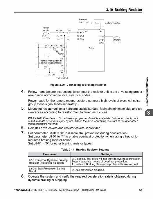
Powersupply
Thermal relay
Motor
Drive
Braking resistor
Thermal relay switch forexternal braking resistor
Fault contact
MC
SA
SA
SA
MCON
MC
OFFTHRX
THRX
TRXMC
TRXMA MC
R/L1 B1 B2
S/L2
T/L3U/T1
V/T2
W/T3
MCCB
Figure 3.20 Connecting a Braking Resistor
4. Follow manufacturer instructions to connect the resistor unit to the drive using properwire gauge according to local electrical codes.
Power leads for the remote mount resistors generate high levels of electrical noise;group these signal leads separately.
5. Mount the resistor unit on a noncombustible surface. Maintain minimum side and topclearances according to resistor manufacturer instructions.
WARNING! Fire Hazard. Do not use improper combustible materials. Failure to comply couldresult in death or serious injury by fire. Attach the drive or braking resistors to metal or othernoncombustible material.
6. Reinstall drive covers and resistor covers, if provided.7. Set parameter L3-04 = “0” to disable stall prevention during deceleration.
Set parameter L8-01 to “1” to enable overheat protection when using a heatsink-mounted braking resistor option.Set L8-01 = “0” for other braking resistor types.
Table 3.14 Braking Resistor Settings
Parameter Settings
L8-01: Internal Dynamic BrakingResistor Protection Selection
0: Disabled. The drive will not provide overheat protection.Supply separate means of overheat protection.1: Enabled. Braking Resistor is protected from overheat.
L3-04: Stall Prevention DuringDecel 0: Stall prevention disabled.
8. Operate the system and verify the required deceleration rate is obtained duringdynamic braking or stopping.
3.10 Braking Resistor
YASKAWA ELECTRIC TOEP C710606 26B YASKAWA AC Drive – J1000 Quick Start Guide 65
3
Elec
tric
al In
stal
latio
n
3.11 Interlocking with Connected MachineryFor safety reasons, applications that may be affected by the operation status of the drive shouldbe set up so that operation can only occur when the drive is ready to operate. A "Drive ready"and "Fault" signal should be assigned to the multi-function outputs to guarantee interlock withapplication.
u Drive Ready SignalWhen the “Drive ready” signal has been set to one of the multi-function contact outputs, thatoutput will close whenever the drive is ready to accept a Run command or is already running.Under the following conditions the Drive ready signal will switch off and remain off, even ifa Run command is entered:• when the power supply is shut off• during a fault• when there is problem with the control power supply• when a parameter setting error makes the drive unable to run even if a Run command has
been entered• when a fault such as overvoltage or undervoltage is triggered as soon as the Run command
is entered• when the drive is in the Programming mode and will not accept a Run command even when
entered.
3.11 Interlocking with Connected Machinery
66 YASKAWA ELECTRIC TOEP C710606 26B YASKAWA AC Drive – J1000 Quick Start Guide
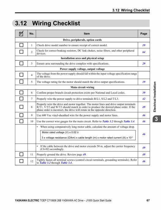
3.12 Wiring ChecklistNo. Item Page
Drive, peripherals, option cards
1 Check drive model number to ensure receipt of correct model. 19
2 Check for correct braking resistors, DC link chokes, noise filters, and other peripheraldevices. 64
Installation area and physical setup
3 Ensure area surrounding the drive complies with specifications. 29
Power supply voltage, output voltage
4 The voltage from the power supply should fall within the input voltage specification rangeof the drive.
5 The voltage rating for the motor should match the drive output specifications. 19
Main circuit wiring
6 Confirm proper branch circuit protection exists per National and Local codes. 39
7 Properly wire the power supply to drive terminals R/L1, S/L2 and T/L3. 42
8Properly wire the drive and motor together. The motor lines and drive output terminalsR/T1, V/T2 and W/T3 should match in order to produce the desired phase order. If thephase order is incorrect, the drive will rotate in the opposite direction.
49
9 Use 600 Vac vinyl-sheathed wire for the power supply and motor lines. 46
10 Use the correct wire gauges for the main circuit. Refer to Table 3.2 through Table 3.4. 46
• When using comparatively long motor cable, calculate the amount of voltage drop.
3 x voltage resistance (Ω/km) x cable length (m) x motor rated current (A) x 10-3
Motor rated voltage (V) x 0.02 ≥ 46
• If the cable between the drive and motor exceeds 50 m, adjust the carrier frequency(C6-02) accordingly. 49
11 Properly ground the drive. Review page 49. 49
12 Tightly fasten all terminal screws (control circuit terminals, grounding terminals). Referto Table 3.2 through Table 3.4.. 46
3.12 Wiring Checklist
YASKAWA ELECTRIC TOEP C710606 26B YASKAWA AC Drive – J1000 Quick Start Guide 67
3
Elec
tric
al In
stal
latio
n
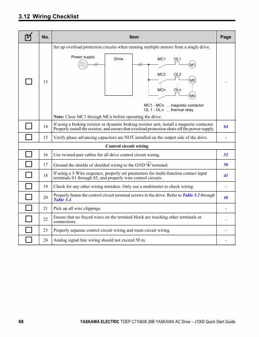
No. Item Page
13
Set up overload protection circuits when running multiple motors from a single drive.
M1OL1
OL2
OLn
MC1
MC2
MCn
M2
Mn
Drive
MC1 - MCn OL 1 - OLn
... magnetic contactor ... thermal relay
Power supply
Note: Close MC1 through MCn before operating the drive.
-
14 If using a braking resistor or dynamic braking resistor unit, install a magnetic contactor.Properly install the resistor, and ensure that overload protection shuts off the power supply. 64
15 Verify phase advancing capacitors are NOT installed on the output side of the drive. -
Control circuit wiring
16 Use twisted-pair cables for all drive control circuit wiring. 52
17 Ground the shields of shielded wiring to the GND terminal. 56
18 If using a 3-Wire sequence, properly set parameters for multi-function contact inputterminals S1 through S5, and properly wire control circuits. 41
19 Check for any other wiring mistakes. Only use a multimeter to check wiring. -
20 Properly fasten the control circuit terminal screws in the drive. Refer to Table 3.2 throughTable 3.4. 46
21 Pick up all wire clippings. -
22 Ensure that no frayed wires on the terminal block are touching other terminals orconnections. -
23 Properly separate control circuit wiring and main circuit wiring. -
24 Analog signal line wiring should not exceed 50 m. -
3.12 Wiring Checklist
68 YASKAWA ELECTRIC TOEP C710606 26B YASKAWA AC Drive – J1000 Quick Start Guide
Start-UpProgramming &
OperationThis chapter explains the functions of the LED operator and howto program the drive for initial operation.
4.1 SECTION SAFETY.............................................704.2 USING THE DIGITAL LED OPERATOR..............734.3 THE DRIVE AND PROGRAMMING MODES.......794.4 START-UP FLOWCHART..................................874.5 BASIC OPERATION..........................................884.6 POWERING UP THE DRIVE.............................1124.7 NO-LOAD OPERATION TEST RUN..................1144.8 TEST RUN WITH LOAD CONNECTED.............1164.9 VERIFYING AND BACKING UP PARAMETER
SETTINGS.......................................................1174.10 TEST RUN CHECKLIST...................................119
4
YASKAWA ELECTRIC TOEP C710606 26B YASKAWA AC Drive – J1000 Quick Start Guide 69

4.1 Section Safety
DANGER
Electrical Shock HazardDo not connect or disconnect wiring while the power is on.Failure to comply will result in death or serious injury.
WARNING
Electrical Shock HazardDo not operate equipment with covers removed.Failure to comply could result in death or serious injury.The diagrams in this section may include drives without covers or safety shields to illustratedetails. Be sure to reinstall covers or shields before operating the drives and run the drivesaccording to the instructions described in this manual.Always ground the motor-side grounding terminal.Improper equipment grounding could result in death or serious injury by contacting themotor case.Do not touch any terminals before the capacitors have fully discharged.Failure to comply could result in death or serious injury.Before wiring terminals, disconnect all power to the equipment. The internal capacitorremains charged even after the power supply is turned off. The charge indicator LED willextinguish when the DC bus voltage is below 50 Vdc. To prevent electric shock, wait atleast one minute after all indicators are off and measure the DC bus voltage level to confirmsafe level.Do not allow unqualified personnel to perform work on the drive.Failure to comply could result in death or serious injury.Installation, maintenance, inspection, and servicing must be performed only by authorizedpersonnel familiar with installation, adjustment and maintenance of AC drives.
4.1 Section Safety
70 YASKAWA ELECTRIC TOEP C710606 26B YASKAWA AC Drive – J1000 Quick Start Guide
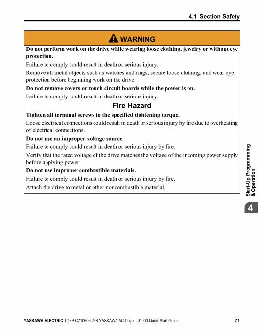
WARNINGDo not perform work on the drive while wearing loose clothing, jewelry or without eyeprotection.Failure to comply could result in death or serious injury.Remove all metal objects such as watches and rings, secure loose clothing, and wear eyeprotection before beginning work on the drive.Do not remove covers or touch circuit boards while the power is on.Failure to comply could result in death or serious injury.
Fire HazardTighten all terminal screws to the specified tightening torque.Loose electrical connections could result in death or serious injury by fire due to overheatingof electrical connections.Do not use an improper voltage source.Failure to comply could result in death or serious injury by fire.Verify that the rated voltage of the drive matches the voltage of the incoming power supplybefore applying power.Do not use improper combustible materials.Failure to comply could result in death or serious injury by fire.Attach the drive to metal or other noncombustible material.
4.1 Section Safety
YASKAWA ELECTRIC TOEP C710606 26B YASKAWA AC Drive – J1000 Quick Start Guide 71
4
Star
t-Up
Prog
ram
min
g&
Ope
ratio
n
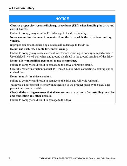
NOTICE
Observe proper electrostatic discharge procedures (ESD) when handling the drive andcircuit boards.Failure to comply may result in ESD damage to the drive circuitry.Never connect or disconnect the motor from the drive while the drive is outputtingvoltage.Improper equipment sequencing could result in damage to the drive.Do not use unshielded cable for control wiring.Failure to comply may cause electrical interference resulting in poor system performance.Use shielded twisted-pair wires and ground the shield to the ground terminal of the drive.Do not allow unqualified personnel to use the product.Failure to comply could result in damage to the drive or braking circuit.Carefully review instruction manual TOBPC72060000 when connecting a braking optionto the drive.Do not modify the drive circuitry.Failure to comply could result in damage to the drive and will void warranty.Yaskawa is not responsible for any modification of the product made by the user. Thisproduct must not be modified.Check all the wiring to ensure that all connections are correct after installing the driveand connecting any other devices.Failure to comply could result in damage to the drive.
4.1 Section Safety
72 YASKAWA ELECTRIC TOEP C710606 26B YASKAWA AC Drive – J1000 Quick Start Guide
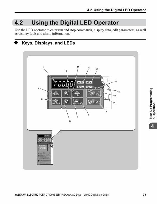
4.2 Using the Digital LED OperatorUse the LED operator to enter run and stop commands, display data, edit parameters, as wellas display fault and alarm information.
u Keys, Displays, and LEDs
P
9
51
2
3
6
78
10
STOP
11
14
1213
15
4
J1000
STOP
据え付け、運転の前には必ず取扱説明書を読むこと。通電中および電源遮断後5分以内はフロントカバーを外さないこと。
400V級インバータの場合は、電源の中性点が接地されていることを確認すること。( 対応)
けが、感電のおそれがあります。危 険
Read manual before installing.Wait 5 minutes for capacitor discharge afterdisconnecting power supply.To conform to requirements, make sureto ground the supply neutral for 400V class.
Risk of electric shock.WARNING
1 周波数指令2 正転逆転選択3 出力周波数4 出力電流5 出力電圧
:::::
::::
6 モニタ7 ベリファイ8 セットアップ9 パラメータ設定
4.2 Using the Digital LED Operator
YASKAWA ELECTRIC TOEP C710606 26B YASKAWA AC Drive – J1000 Quick Start Guide 73
4
Star
t-Up
Prog
ram
min
g&
Ope
ratio
n
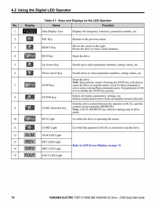
Table 4.1 Keys and Displays on the LED OperatorNo. Display Name Function
1 Data Display Area Displays the frequency reference, parameter number, etc.
2 ESC Key Returns to the previous menu.
3 RESET Key Moves the cursor to the right.Resets the drive to clear a fault situation.
4 RUN Key Starts the drive.
5 Up Arrow Key Scrolls up to select parameter numbers, setting values, etc.
6 Down Arrow Key Scrolls down to select parameter numbers, setting values, etc.
7 STOP STOP Key
Stops the drive.Note: Stop priority circuit. Pressing the STOP key will alwayscause the drive to stop the motor, even if a Run command isactive at any external Run command source. Set parameter o2-06to 0 to disable the STOP key priority.
8 ENTER Key Selects all modes, parameters, settings, etc.Selects a menu item to move from one display screen to the next.
9 LO/RE Selection KeySwitches drive control between the operator (LOCAL) and thecontrol circuit terminals (REMOTE).Note: LOCAL/REMOTE key effective during stop in drivemode.
10 RUN Light Lit while the drive is operating the motor.
11 LO/RE Light Lit while the operator (LOCAL) is selected to run the drive.
12 ALM LED Light
Refer to LED Screen Displays on page 76.13 REV LED Light
14 DRV LED Light
15 FOUT LED Light
4.2 Using the Digital LED Operator
74 YASKAWA ELECTRIC TOEP C710606 26B YASKAWA AC Drive – J1000 Quick Start Guide
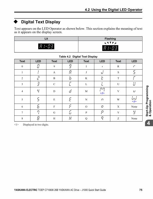
u Digital Text DisplayText appears on the LED Operator as shown below. This section explains the meaning of textas it appears on the display screen.
Lit Flashing
Table 4.2 Digital Text DisplayText LED Text LED Text LED Text LED
0 9 I R
1 A J S
2 B K T
3 C L U
4 D M<1>
V
5 E N W<1>
6 F O X None
7 G P Y
8 H Q Z None
<1> Displayed in two digits.
4.2 Using the Digital LED Operator
YASKAWA ELECTRIC TOEP C710606 26B YASKAWA AC Drive – J1000 Quick Start Guide 75
4
Star
t-Up
Prog
ram
min
g&
Ope
ratio
n
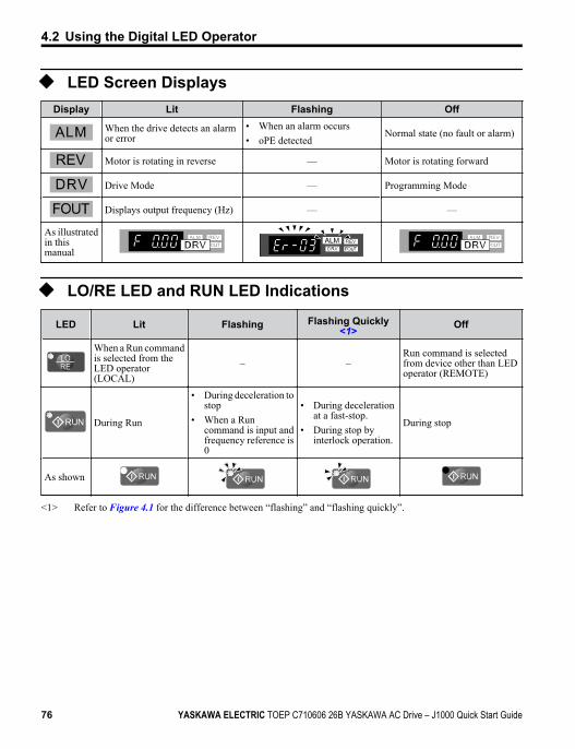
u LED Screen DisplaysDisplay Lit Flashing Off
When the drive detects an alarmor error
• When an alarm occurs• oPE detected
Normal state (no fault or alarm)
Motor is rotating in reverse — Motor is rotating forward
Drive Mode — Programming Mode
Displays output frequency (Hz) — —
As illustratedin thismanual
STOPu LO/RE LED and RUN LED Indications
LED Lit Flashing Flashing Quickly<1> Off
When a Run commandis selected from theLED operator(LOCAL)
– –Run command is selectedfrom device other than LEDoperator (REMOTE)
During Run
• During deceleration tostop
• When a Runcommand is input andfrequency reference is0
• During decelerationat a fast-stop.
• During stop byinterlock operation.
During stop
As shown
<1> Refer to Figure 4.1 for the difference between “flashing” and “flashing quickly”.
4.2 Using the Digital LED Operator
76 YASKAWA ELECTRIC TOEP C710606 26B YASKAWA AC Drive – J1000 Quick Start Guide
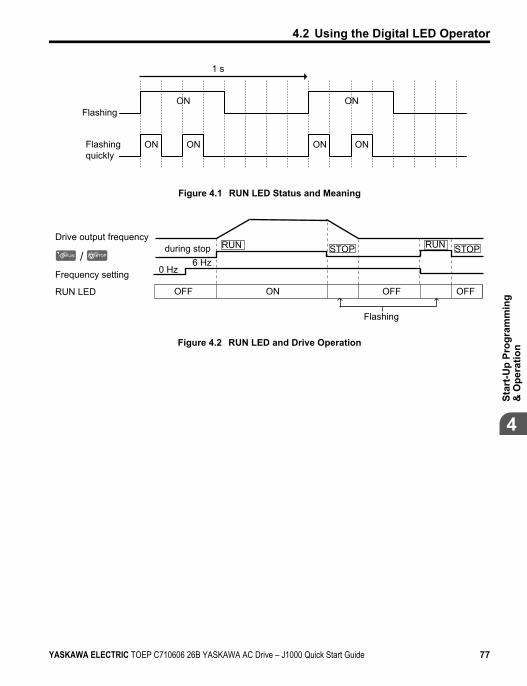
Flashing
ON ON
ON
ON ON
ON
1 s
Flashingquickly
Figure 4.1 RUN LED Status and Meaning
/
Drive output frequencyduring stop
Frequency setting
OFF ON
Flashing
OFFOFFRUN LED
RUN
0 Hz6 Hz
RUNSTOP STOP
Figure 4.2 RUN LED and Drive Operation
4.2 Using the Digital LED Operator
YASKAWA ELECTRIC TOEP C710606 26B YASKAWA AC Drive – J1000 Quick Start Guide 77
4
Star
t-Up
Prog
ram
min
g&
Ope
ratio
n
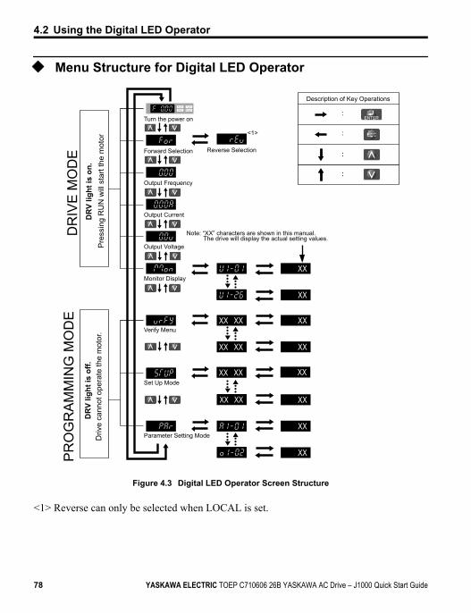
u Menu Structure for Digital LED Operator
XXXX
XX
XX
XX
XX
XX
XX
XX
XXXX
XXXX XX
XXXX
:
:
:
:
Turn the power on
Forward Selection Reverse Selection
Output Frequency
Output Current
Output Voltage
Monitor Display
Note: “XX” characters are shown in this manual. The drive will display the actual setting values.
<1>
Verify Menu
Set Up Mode
Parameter Setting Mode
Description of Key Operations
PR
OG
RA
MM
ING
MO
DE
DR
IVE
MO
DE :
:
Figure 4.3 Digital LED Operator Screen Structure
<1> Reverse can only be selected when LOCAL is set.
4.2 Using the Digital LED Operator
78 YASKAWA ELECTRIC TOEP C710606 26B YASKAWA AC Drive – J1000 Quick Start Guide
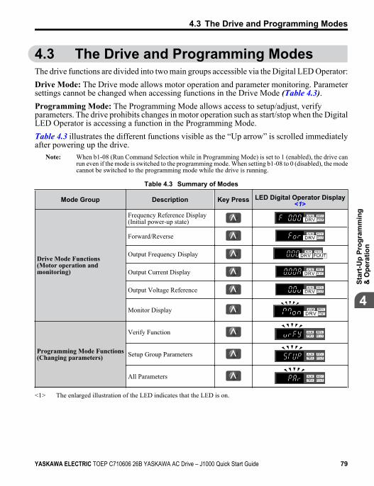
4.3 The Drive and Programming ModesThe drive functions are divided into two main groups accessible via the Digital LED Operator:Drive Mode: The Drive mode allows motor operation and parameter monitoring. Parametersettings cannot be changed when accessing functions in the Drive Mode (Table 4.3).Programming Mode: The Programming Mode allows access to setup/adjust, verifyparameters. The drive prohibits changes in motor operation such as start/stop when the DigitalLED Operator is accessing a function in the Programming Mode.Table 4.3 illustrates the different functions visible as the “Up arrow” is scrolled immediatelyafter powering up the drive.
Note: When b1-08 (Run Command Selection while in Programming Mode) is set to 1 (enabled), the drive canrun even if the mode is switched to the programming mode. When setting b1-08 to 0 (disabled), the modecannot be switched to the programming mode while the drive is running.
Table 4.3 Summary of Modes
Mode Group Description Key Press LED Digital Operator Display<1>
Drive Mode Functions(Motor operation andmonitoring)
Frequency Reference Display(Initial power-up state)
STOP
Forward/Reverse
STOP
Output Frequency Display
STOP
Output Current Display
STOP
Output Voltage Reference
STOP
Monitor Display
STOP
Programming Mode Functions(Changing parameters)
Verify Function
STOP
Setup Group Parameters
STOP
All Parameters
STOP
<1> The enlarged illustration of the LED indicates that the LED is on.
4.3 The Drive and Programming Modes
YASKAWA ELECTRIC TOEP C710606 26B YASKAWA AC Drive – J1000 Quick Start Guide 79
4
Star
t-Up
Prog
ram
min
g&
Ope
ratio
n
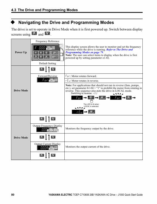
u Navigating the Drive and Programming ModesThe drive is set to operate in Drive Mode when it is first powered up. Switch between displayscreens using and .
Power Up
Frequency Reference
STOP
Default Setting
This display screen allows the user to monitor and set the frequencyreference while the drive is running. Refer to The Drive and Programming Modes on page 79.Note: The user can select items to display when the drive is firstpowered up by setting parameter o1-02.
Drive Mode
Forward/Reverse
STOP
: Motor rotates forward.
: Motor rotates in reverse.
Note: For applications that should not run in reverse (fans, pumps,etc.), set parameter b1-04 = “1” to prohibit the motor from rotating inreverse. This sequence also puts the drive in LOCAL mode.
The LED is lit when LOCAL is selected
Switching to reverse:
Drive Mode
Output Frequency Display
STOP
Monitors the frequency output by the drive.
Output Current Display
STOP
Monitors the output current of the drive.
4.3 The Drive and Programming Modes
80 YASKAWA ELECTRIC TOEP C710606 26B YASKAWA AC Drive – J1000 Quick Start Guide
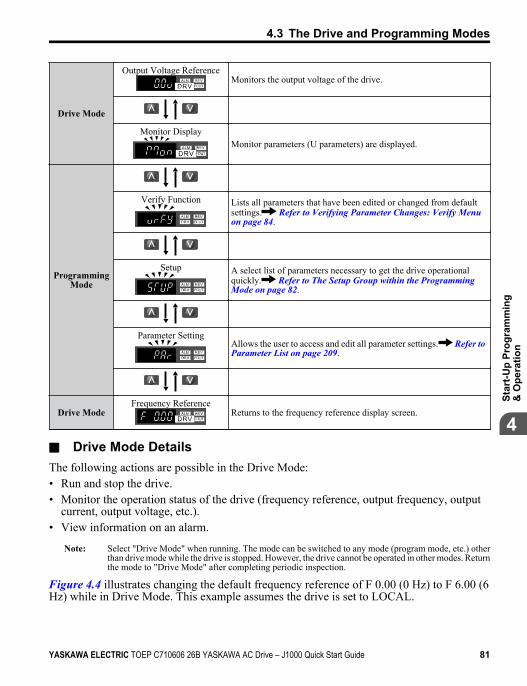
Drive Mode
Output Voltage Reference
STOP
Monitors the output voltage of the drive.
Monitor Display
STOP
Monitor parameters (U parameters) are displayed.
ProgrammingMode
Verify Function
STOP
Lists all parameters that have been edited or changed from defaultsettings. Refer to Verifying Parameter Changes: Verify Menu on page 84.
Setup
STOP
A select list of parameters necessary to get the drive operationalquickly. Refer to The Setup Group within the Programming Mode on page 82.
Parameter Setting
STOP
Allows the user to access and edit all parameter settings. Refer to Parameter List on page 209.
Drive ModeFrequency Reference
STOP
Returns to the frequency reference display screen.
n Drive Mode DetailsThe following actions are possible in the Drive Mode:• Run and stop the drive.• Monitor the operation status of the drive (frequency reference, output frequency, output
current, output voltage, etc.).• View information on an alarm.
Note: Select "Drive Mode" when running. The mode can be switched to any mode (program mode, etc.) otherthan drive mode while the drive is stopped. However, the drive cannot be operated in other modes. Returnthe mode to "Drive Mode" after completing periodic inspection.
Figure 4.4 illustrates changing the default frequency reference of F 0.00 (0 Hz) to F 6.00 (6Hz) while in Drive Mode. This example assumes the drive is set to LOCAL.
4.3 The Drive and Programming Modes
YASKAWA ELECTRIC TOEP C710606 26B YASKAWA AC Drive – J1000 Quick Start Guide 81
4
Star
t-Up
Prog
ram
min
g&
Ope
ratio
n
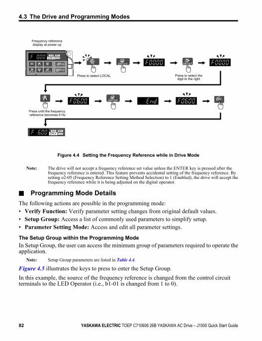
STOP
Frequency reference display at power up
Press to select LOCAL
Press until the frequency reference becomes 6 Hz
Press to select thedigit to the right
Figure 4.4 Setting the Frequency Reference while in Drive Mode
Note: The drive will not accept a frequency reference set value unless the ENTER key is pressed after thefrequency reference is entered. This feature prevents accidental setting of the frequency reference. Bysetting o2-05 (Frequency Reference Setting Method Selection) to 1 (Enabled), the drive will accept thefrequency reference while it is being adjusted on the digital operator.
n Programming Mode DetailsThe following actions are possible in the programming mode:• Verify Function: Verify parameter setting changes from original default values.• Setup Group: Access a list of commonly used parameters to simplify setup.• Parameter Setting Mode: Access and edit all parameter settings.
The Setup Group within the Programming ModeIn Setup Group, the user can access the minimum group of parameters required to operate theapplication.
Note: Setup Group parameters are listed in Table 4.4.
Figure 4.5 illustrates the keys to press to enter the Setup Group.In this example, the source of the frequency reference is changed from the control circuitterminals to the LED Operator (i.e., b1-01 is changed from 1 to 0).
4.3 The Drive and Programming Modes
82 YASKAWA ELECTRIC TOEP C710606 26B YASKAWA AC Drive – J1000 Quick Start Guide
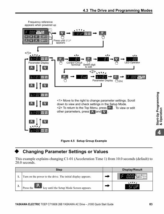
STOP
STOP
STOP
STOP
STOP
(2x)
<1> Move to the right to change parameter settings. Scroll down to view and check settings in the Setup Mode.<2> To return to the Top Menu, press . To view or editother parameters, press and .
Control CircuitTerminal Select digit
to edit
Parameter Display
LED Operator
Frequency reference appears when powered up
Parameter Display
Press until appears
<1>
<2>
Figure 4.5 Setup Group Example
u Changing Parameter Settings or ValuesThis example explains changing C1-01 (Acceleration Time 1) from 10.0 seconds (default) to20.0 seconds.
Step Display/Result
1. Turn on the power to the drive. The initial display appears.
2.Press the key until the Setup Mode Screen appears.
4.3 The Drive and Programming Modes
YASKAWA ELECTRIC TOEP C710606 26B YASKAWA AC Drive – J1000 Quick Start Guide 83
4
Star
t-Up
Prog
ram
min
g&
Ope
ratio
n
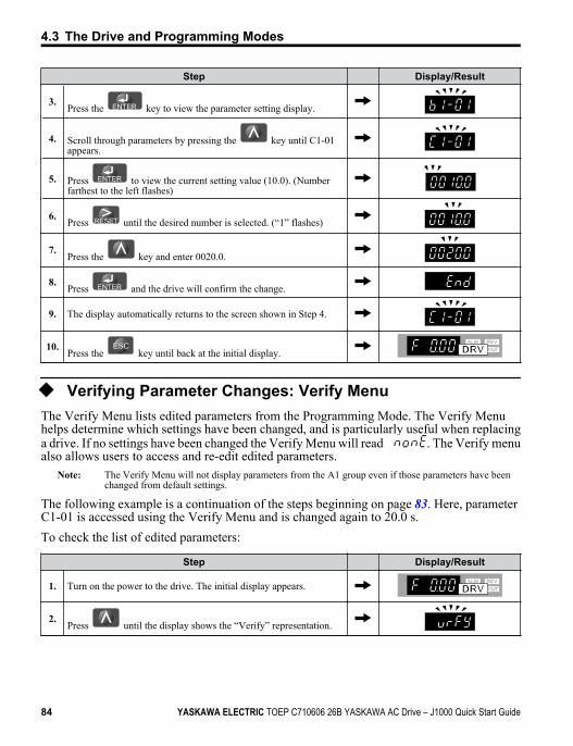
Step Display/Result
3.Press the key to view the parameter setting display.
4. Scroll through parameters by pressing the key until C1-01appears.
5. Press to view the current setting value (10.0). (Numberfarthest to the left flashes)
6. Press until the desired number is selected. (“1” flashes)
7.Press the key and enter 0020.0.
8.Press and the drive will confirm the change.
9. The display automatically returns to the screen shown in Step 4.
10. Press the key until back at the initial display.
u Verifying Parameter Changes: Verify MenuThe Verify Menu lists edited parameters from the Programming Mode. The Verify Menuhelps determine which settings have been changed, and is particularly useful when replacinga drive. If no settings have been changed the Verify Menu will read . The Verify menualso allows users to access and re-edit edited parameters.
Note: The Verify Menu will not display parameters from the A1 group even if those parameters have beenchanged from default settings.
The following example is a continuation of the steps beginning on page 83. Here, parameter C1-01 is accessed using the Verify Menu and is changed again to 20.0 s.To check the list of edited parameters:
Step Display/Result
1. Turn on the power to the drive. The initial display appears.
2.Press until the display shows the “Verify” representation.
4.3 The Drive and Programming Modes
84 YASKAWA ELECTRIC TOEP C710606 26B YASKAWA AC Drive – J1000 Quick Start Guide
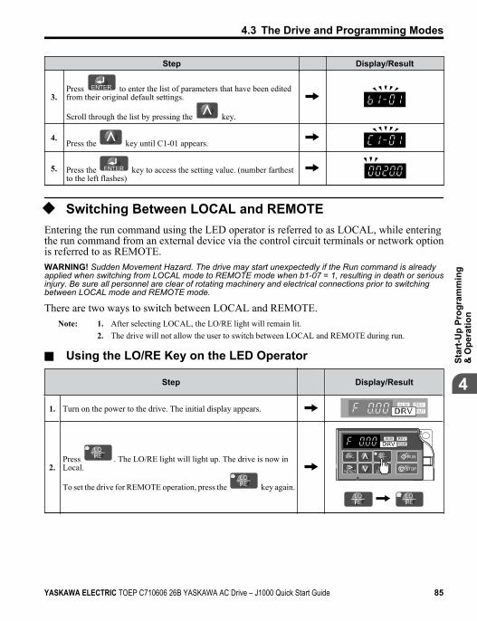
Step Display/Result
3.Press to enter the list of parameters that have been editedfrom their original default settings.
Scroll through the list by pressing the key.
4.Press the key until C1-01 appears.
5. Press the key to access the setting value. (number farthestto the left flashes)
u Switching Between LOCAL and REMOTEEntering the run command using the LED operator is referred to as LOCAL, while enteringthe run command from an external device via the control circuit terminals or network optionis referred to as REMOTE.WARNING! Sudden Movement Hazard. The drive may start unexpectedly if the Run command is alreadyapplied when switching from LOCAL mode to REMOTE mode when b1-07 = 1, resulting in death or seriousinjury. Be sure all personnel are clear of rotating machinery and electrical connections prior to switchingbetween LOCAL mode and REMOTE mode.
There are two ways to switch between LOCAL and REMOTE.Note: 1. After selecting LOCAL, the LO/RE light will remain lit.
2. The drive will not allow the user to switch between LOCAL and REMOTE during run.
n Using the LO/RE Key on the LED Operator
Step Display/Result
1. Turn on the power to the drive. The initial display appears.
2.Press . The LO/RE light will light up. The drive is now inLocal.
To set the drive for REMOTE operation, press the key again.
STOP
4.3 The Drive and Programming Modes
YASKAWA ELECTRIC TOEP C710606 26B YASKAWA AC Drive – J1000 Quick Start Guide 85
4
Star
t-Up
Prog
ram
min
g&
Ope
ratio
n
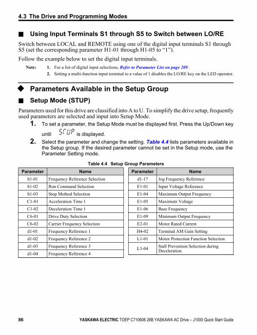
n Using Input Terminals S1 through S5 to Switch between LO/RESwitch between LOCAL and REMOTE using one of the digital input terminals S1 throughS5 (set the corresponding parameter H1-01 through H1-05 to “1”).Follow the example below to set the digital input terminals.
Note: 1. For a list of digital input selections, Refer to Parameter List on page 209.2. Setting a multi-function input terminal to a value of 1 disables the LO/RE key on the LED operator.
u Parameters Available in the Setup Group
n Setup Mode (STUP)Parameters used for this drive are classified into A to U. To simplify the drive setup, frequentlyused parameters are selected and input into Setup Mode.
1. To set a parameter, the Setup Mode must be displayed first. Press the Up/Down key
until is displayed.2. Select the parameter and change the setting. Table 4.4 lists parameters available in
the Setup group. If the desired parameter cannot be set in the Setup mode, use theParameter Setting mode.
Table 4.4 Setup Group ParametersParameter Name
b1-01 Frequency Reference Selection
b1-02 Run Command Selection
b1-03 Stop Method Selection
C1-01 Acceleration Time 1
C1-02 Deceleration Time 1
C6-01 Drive Duty Selection
C6-02 Carrier Frequency Selection
d1-01 Frequency Reference 1
d1-02 Frequency Reference 2
d1-03 Frequency Reference 3
d1-04 Frequency Reference 4
Parameter Named1-17 Jog Frequency Reference
E1-01 Input Voltage Reference
E1-04 Maximum Output Frequency
E1-05 Maximum Voltage
E1-06 Base Frequency
E1-09 Minimum Output Frequency
E2-01 Motor Rated Current
H4-02 Terminal AM Gain Setting
L1-01 Motor Protection Function Selection
L3-04 Stall Prevention Selection duringDeceleration
4.3 The Drive and Programming Modes
86 YASKAWA ELECTRIC TOEP C710606 26B YASKAWA AC Drive – J1000 Quick Start Guide
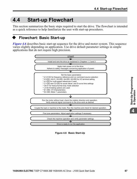
4.4 Start-up FlowchartThis section summarizes the basic steps required to start the drive. The flowchart is intendedas a quick reference to help familiarize the user with start-up procedures.
u Flowchart: Basic Start-upFigure 4.6 describes basic start-up sequence for the drive and motor system. This sequencevaries slightly depending on application. Use drive default parameter settings in simpleapplications that do not require high precision.
Install and wire the drive as explained in Chapters 1, 2 and 3
Run the motor without load; check the rotation direction and operation.Verify external signal commands to the drive work as desired.
Couple the load or machine to the motor. Run the machine and check for desired operation.
Fine tune parameters. Adjust application settings if necessary.
Check the machine operation and verify parameter settings.
Drive is ready to run the application.
START
Apply main power on to the drive.Adhere to safety messages concerning application of power.
Set the basic parameters:* b1-01/02 for frequency reference and run command source selection* H1-oo, H2-01, H3-oo, H4-oo, H5-oo for I/O terminal setting* d1-oo for multi-speed references if used* C1-oo and C2-oo for accel./decel. and S-curve time settings* C6-01 for heavy/normal duty mode selection* L3-04 if braking options are used * E1-oo, V/f Characteristics* E2-oo, Motor 1 parameters
Figure 4.6 Basic Start-Up
4.4 Start-up Flowchart
YASKAWA ELECTRIC TOEP C710606 26B YASKAWA AC Drive – J1000 Quick Start Guide 87
4
Star
t-Up
Prog
ram
min
g&
Ope
ratio
n
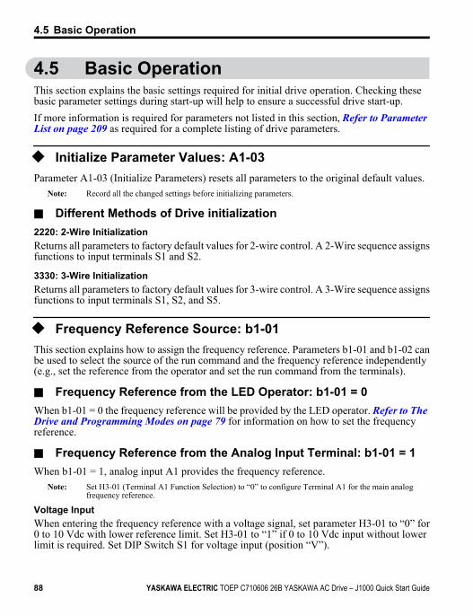
4.5 Basic OperationThis section explains the basic settings required for initial drive operation. Checking thesebasic parameter settings during start-up will help to ensure a successful drive start-up.If more information is required for parameters not listed in this section, Refer to Parameter List on page 209 as required for a complete listing of drive parameters.
u Initialize Parameter Values: A1-03Parameter A1-03 (Initialize Parameters) resets all parameters to the original default values.
Note: Record all the changed settings before initializing parameters.
n Different Methods of Drive initialization2220: 2-Wire InitializationReturns all parameters to factory default values for 2-wire control. A 2-Wire sequence assignsfunctions to input terminals S1 and S2.
3330: 3-Wire InitializationReturns all parameters to factory default values for 3-wire control. A 3-Wire sequence assignsfunctions to input terminals S1, S2, and S5.
u Frequency Reference Source: b1-01This section explains how to assign the frequency reference. Parameters b1-01 and b1-02 canbe used to select the source of the run command and the frequency reference independently(e.g., set the reference from the operator and set the run command from the terminals).
n Frequency Reference from the LED Operator: b1-01 = 0When b1-01 = 0 the frequency reference will be provided by the LED operator. Refer to The Drive and Programming Modes on page 79 for information on how to set the frequencyreference.
n Frequency Reference from the Analog Input Terminal: b1-01 = 1When b1-01 = 1, analog input A1 provides the frequency reference.
Note: Set H3-01 (Terminal A1 Function Selection) to “0” to configure Terminal A1 for the main analogfrequency reference.
Voltage InputWhen entering the frequency reference with a voltage signal, set parameter H3-01 to “0” for0 to 10 Vdc with lower reference limit. Set H3-01 to “1” if 0 to 10 Vdc input without lowerlimit is required. Set DIP Switch S1 for voltage input (position “V”).
4.5 Basic Operation
88 YASKAWA ELECTRIC TOEP C710606 26B YASKAWA AC Drive – J1000 Quick Start Guide
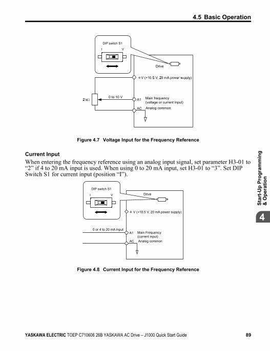
Drive
A10 to 10 V
AC
I V
Main frequency(voltage or current input)Analog common
DIP switch S1
Figure 4.7 Voltage Input for the Frequency Reference
Current InputWhen entering the frequency reference using an analog input signal, set parameter H3-01 to“2” if 4 to 20 mA input is used. When using 0 to 20 mA input, set H3-01 to “3”. Set DIPSwitch S1 for current input (position “I”).
V (+10.5 V, 20 mA power supply)
0 or 4 to 20 mA input
DIP switch S1
I V Drive
A1 Main Frequency(current input)
AC Analog common
Figure 4.8 Current Input for the Frequency Reference
4.5 Basic Operation
YASKAWA ELECTRIC TOEP C710606 26B YASKAWA AC Drive – J1000 Quick Start Guide 89
4
Star
t-Up
Prog
ram
min
g&
Ope
ratio
n
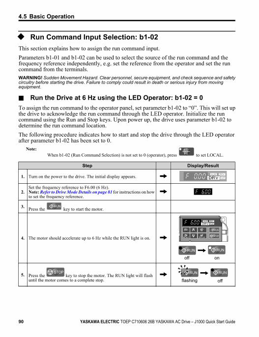
u Run Command Input Selection: b1-02This section explains how to assign the run command input.Parameters b1-01 and b1-02 can be used to select the source of the run command and thefrequency reference independently, e.g. set the reference from the operator and set the runcommand from the terminals.WARNING! Sudden Movement Hazard. Clear personnel, secure equipment, and check sequence and safetycircuitry before starting the drive. Failure to comply could result in death or serious injury from movingequipment.
n Run the Drive at 6 Hz using the LED Operator: b1-02 = 0To assign the run command to the operator panel, set parameter b1-02 to “0”. This will set upthe drive to acknowledge the run command through the LED operator. Initialize the runcommand using the Run and Stop keys. Upon power up, the drive uses parameter b1-02 todetermine the run command location.The following procedure indicates how to start and stop the drive through the LED operatorafter parameter b1-02 has been set to 0.
Note:When b1-02 (Run Command Selection) is not set to 0 (operator), press to set LOCAL.
Step Display/Result
1. Turn on the power to the drive. The initial display appears.
2.Set the frequency reference to F6.00 (6 Hz).Note: Refer to Drive Mode Details on page 81 for instructions on howto set the frequency reference.
3. Press the key to start the motor.
4. The motor should accelerate up to 6 Hz while the RUN light is on. STOP
off on
5. Press the STOP
key to stop the motor. The RUN light will flashuntil the motor comes to a complete stop. flashing off
4.5 Basic Operation
90 YASKAWA ELECTRIC TOEP C710606 26B YASKAWA AC Drive – J1000 Quick Start Guide
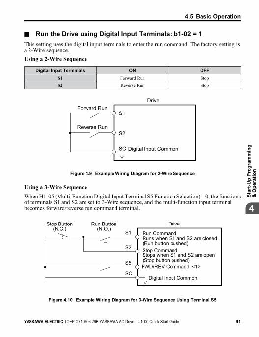
n Run the Drive using Digital Input Terminals: b1-02 = 1This setting uses the digital input terminals to enter the run command. The factory setting isa 2-Wire sequence.Using a 2-Wire Sequence
Digital Input Terminals ON OFFS1 Forward Run Stop
S2 Reverse Run Stop
S1
S2
SC
DriveForward Run
Reverse Run
Digital Input Common
Figure 4.9 Example Wiring Diagram for 2-Wire Sequence
Using a 3-Wire SequenceWhen H1-05 (Multi-Function Digital Input Terminal S5 Function Selection) = 0, the functionsof terminals S1 and S2 are set to 3-Wire sequence, and the multi-function input terminalbecomes forward/reverse run command terminal.
S1
S2
S5
SC
Run CommandRuns when S1 and S2 are closed
DriveStop Button(N.C.)
Run Button(N.O.)
Stop CommandStops when S1 and S2 are open
FWD/REV Command <1>
Digital Input Common
(Run button pushed)
(Stop button pushed)
Figure 4.10 Example Wiring Diagram for 3-Wire Sequence Using Terminal S5
4.5 Basic Operation
YASKAWA ELECTRIC TOEP C710606 26B YASKAWA AC Drive – J1000 Quick Start Guide 91
4
Star
t-Up
Prog
ram
min
g&
Ope
ratio
n
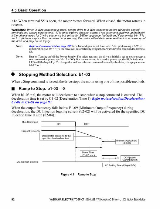
<1> When terminal S5 is open, the motor rotates forward. When closed, the motor rotates inreverse.WARNING! When 3-Wire sequence is used, set the drive to 3-Wire sequence before wiring the controlterminals and ensure parameter b1-17 is set to 0 (drive does not accept a run command at power up (default)).If the drive is wired for 3-Wire sequence but set up for 2-Wire sequence (default) and if parameter b1-17 isset to 1 (drive accepts a Run command at power up), the motor will rotate in reverse direction at power up ofthe drive and may cause injury.
Note: Refer to Parameter List on page 209 for a list of digital input functions. After performing a 3-Wireinitialization (A1-03 = “3”), the drive will automatically assign the forward/reverse command to terminalS5.
Note: Run by Turning on/off the Power Supply. For safety reasons, the drive is initially set up not to accept arun command at power up (b1-17 = "0"). If a run command is issued at power up, the RUN indicatorLED will flash quickly. To change this and have the run command issued by the drive, change parameterb1-17 to 1.
u Stopping Method Selection: b1-03When a Stop command is issued, the drive stops the motor using one of two possible methods.
n Ramp to Stop: b1-03 = 0When b1-03 = 0, the motor will decelerate to a stop when a stop command is entered. Thedeceleration time is set by C1-02 (Deceleration Time 1). Refer to Acceleration/Deceleration: C1-01 to C1-04 on page 93.When the output frequency falls below E1-09 (Minimum Output Frequency) duringdeceleration, the DC Injection braking current (b2-02) will be activated for the specified DCInjection time at stop (b2-04).
Run Command
Decelerates according to the specified deceleration time
Minimum Output Freq.(E1-09)
DC Injection Current (b2-02)
DC Braking Time at Stop (b2-04)
Decel Time(C1-02, etc.)
Output Frequency
DC Injection Braking
ON OFF
Figure 4.11 Ramp to Stop
4.5 Basic Operation
92 YASKAWA ELECTRIC TOEP C710606 26B YASKAWA AC Drive – J1000 Quick Start Guide
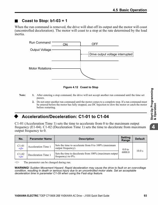
n Coast to Stop: b1-03 = 1When the run command is removed, the drive will shut off its output and the motor will coast(uncontrolled deceleration). The motor will coast to a stop at the rate determined by the loadinertia.
Drive output voltage interrupted
Run Command
Output Voltage
Motor Rotations
ON OFF
Figure 4.12 Coast to Stop
Note: 1. After entering a stop command, the drive will not accept another run command until the time setpasses.
2. Do not enter another run command until the motor comes to a complete stop. If a run command mustbe entered before the motor has fully stopped, use DC Injection to slow the motor or catch the motorbefore restarting.
u Acceleration/Deceleration: C1-01 to C1-04C1-01 (Acceleration Time 1) sets the time to accelerate from 0 to the maximum outputfrequency (E1-04). C1-02 (Deceleration Time 1) sets the time to decelerate from maximumoutput frequency to 0.
No. Parameter Name Description SettingRange Default
C1-01<1> Acceleration Time 1 Sets the time to accelerate from 0 to 100% (maximum
output frequency). 0.0 to6000.0 10.0 s
C1-02<1> Deceleration Time 1 Sets the time to decelerate from 100% (maximum output
frequency) to 0%.
<1> The parameter can be changed during run.
WARNING! Sudden Movement Hazard. Rapid deceleration may cause the drive to fault on an overvoltagecondition, resulting in death or serious injury due to an uncontrolled motor state. Set an acceptabledeceleration time in parameter C1-09 when using the Fast-stop feature.
4.5 Basic Operation
YASKAWA ELECTRIC TOEP C710606 26B YASKAWA AC Drive – J1000 Quick Start Guide 93
4
Star
t-Up
Prog
ram
min
g&
Ope
ratio
n
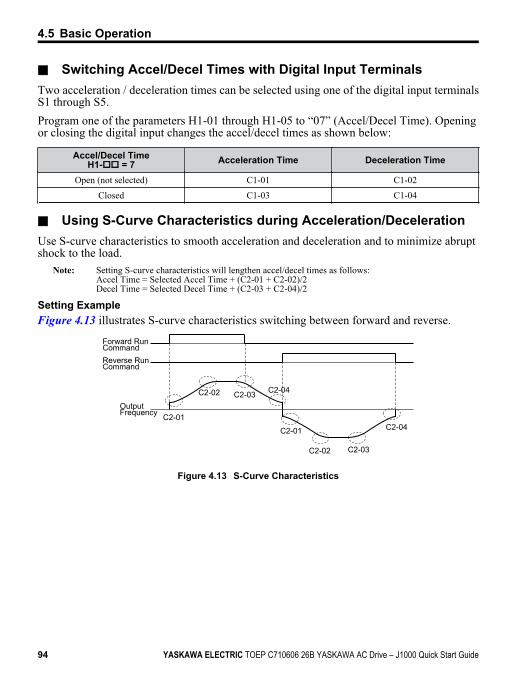
n Switching Accel/Decel Times with Digital Input TerminalsTwo acceleration / deceleration times can be selected using one of the digital input terminalsS1 through S5.Program one of the parameters H1-01 through H1-05 to “07” (Accel/Decel Time). Openingor closing the digital input changes the accel/decel times as shown below:
Accel/Decel TimeH1-oo = 7 Acceleration Time Deceleration Time
Open (not selected) C1-01 C1-02
Closed C1-03 C1-04
n Using S-Curve Characteristics during Acceleration/DecelerationUse S-curve characteristics to smooth acceleration and deceleration and to minimize abruptshock to the load.
Note: Setting S-curve characteristics will lengthen accel/decel times as follows:Accel Time = Selected Accel Time + (C2-01 + C2-02)/2Decel Time = Selected Decel Time + (C2-03 + C2-04)/2
Setting ExampleFigure 4.13 illustrates S-curve characteristics switching between forward and reverse.
C2-02
C2-01
C2-03 C2-04
C2-02
C2-01
C2-03
C2-04
Forward RunCommandReverse RunCommand
Output Frequency
Figure 4.13 S-Curve Characteristics
4.5 Basic Operation
94 YASKAWA ELECTRIC TOEP C710606 26B YASKAWA AC Drive – J1000 Quick Start Guide
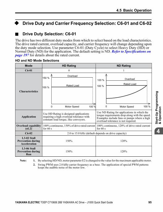
u Drive Duty and Carrier Frequency Selection: C6-01 and C6-02
n Drive Duty Selection: C6-01The drive has two different duty modes from which to select based on the load characteristics.The drive rated current, overload capacity, and carrier frequency will change depending uponthe duty mode selection. Use parameter C6-01 (Duty Cycle) to select Heavy Duty (HD) orNormal Duty (ND) for the application. The default setting is ND. Refer to Specifications on page 197 for details about the rated current.HD and ND Mode Selections
Mode HD Rating ND RatingC6-01 0 1
Characteristics100 %
100 %0 Motor Speed
Rated Load
Overload150 %
Motor Speed0
100 %
100 %
120 %Rated Load
Overload
ApplicationUse HD Rating is designed applicationsrequiring a high overload tolerance withconstant load torque, like conveyors.
Use ND Rating for applications in which thetorque requirements drop along with the speed.Examples include fans or pumps where a highoverload tolerance is not required.
Overload capability(oL2)
100% continuous, 150% of drive rated currentfor 60 s
100% continuous, 120% of drive rated currentfor 60 s
C6-02 2.0 to 15.0 kHz (default depends on drive capacity)
L3-02 StallPrevention during
Acceleration150% 120%
L3-06 StallPrevention during
Run150% 120%
Note: 1. By selecting HD/ND, motor parameter E2 is changed to the value for the maximum applicable motor.2. Swing PWM uses 2.0 kHz carrier frequency as a base. The application of special PWM patterns
keeps the audible noise of the motor low.
4.5 Basic Operation
YASKAWA ELECTRIC TOEP C710606 26B YASKAWA AC Drive – J1000 Quick Start Guide 95
4
Star
t-Up
Prog
ram
min
g&
Ope
ratio
n
n Carrier Frequency Selection: C6-02Fixed Carrier FrequenciesThe carrier frequency can be set using parameter C6-02 as shown in table below.
Parameter Name Description Setting Range Default
C6-02 Carrierfrequency
1 : 2.0 kHz2 : 5.0 kHz3 : 8.0 kHz4 : 10.0 kHz5 : 12.5 kHz6 : 15.0 kHz7: Swing PWMF : User defined (C6-03 to C6-05)
1 to F Depends ondrive size
Note: Settings 7 through A for parameter C6-02 use a Swing PWM equivalent to a 2 kHz audible noise. Thisfunction turns the motor noise into a less obtrusive white noise.
Note: The upper limit for the carrier frequency is determined by drive capacity.
Precautions when setting parameter C6-02:
Symptom Possible SolutionSpeed and torque are unstable at low speeds.
Lower the carrier frequency.Noise from the drive is affecting peripheral devices.
Excessive leakage current from the drive.
Wiring between the drive and motor is too long. <1>
Motor acoustic noise is too loud. Increase the carrier frequency or use Swing PWM.
<1> The carrier frequency may need to be lowered if the motor cable is too long. Refer to the table below.
Wiring Distance Up to 50 m Up to 100 m Greater than 100 mC6-02 (Carrier Frequency Selection) 1 to F (15 kHz) 1 to 2 (5 kHz), 7 1 (2 kHz), 7
Carrier Frequency Setting Error (oPE11)A carrier frequency setup error (oPE11) will occur when carrier frequency gain (C6-05) isgreater than 6 and C6-03 < C6-04.
Note: Refer to Troubleshooting without Fault Display on page 149 for information on operator errors (oPE).
n Carrier Frequency and Drive Overload Current LevelThe tables below show the drive output current depending on the carrier frequency settings.The 2 kHz value is equal to the Normal Duty (C6-01 = 1) rated current, the 8/10 kHz valueis equal to the Heavy Duty rated current. The carrier frequency determines the output currentlinearly. Use the data below to calculate output current values for carrier frequencies not listedin the tables.
Note: In Heavy Duty mode the maximum rated output current is equal to the 8/10 kHz value, even if the carrierfrequency is reduced.
4.5 Basic Operation
96 YASKAWA ELECTRIC TOEP C710606 26B YASKAWA AC Drive – J1000 Quick Start Guide
Table 4.5 Drives with Heavy Duty Default Carrier Frequency of 10 kHz200 V Single Phase Units 200 V Three Phase Units
Model JoRated Current [A]
Model JoRated Current [A]
2 kHz 10 kHz 15 kHz 2 kHz 10 kHz 15 kHzBA0001 1.2 0.8 0.6 2A0001 1.2 0.8 0.6
BA0002 1.9 1.6 1.3 2A0002 1.9 1.6 1.3
BA0003 3.5 3.0 2.4 2A0004 3.5 3.0 2.4
BA0006 6.0 5.0 4.0 2A0006 6.0 5.0 4.0
Table 4.6 Drives with Heavy Duty Default Carrier Frequency of 8 kHz200 V Single Phase Units 200 V Three Phase Units 400 V Three Phase Units
ModelJo
Rated Current [A] ModelJo
Rated Current [A] ModelJo
Rated Current [A]2 kHz 8 kHz 15 kHz 2 kHz 8 kHz 15 kHz 2 kHz 8 kHz 15 kHz
BA0010 9.6 8.0 6.4 — — — — 4A0001 1.2 1.2 0.7— — — — 2A0010 9.6 8.0 6.4 4A0002 2.1 1.8 1.1— — — — 2A0012 12.0 11.0 8.8 4A0004 4.1 3.4 2.0
— — — — — — — — 4A0005 5.4 4.8 2.9
— — — — 2A0020 19.6 17.5 14.0 4A0007 6.9 5.5 3.3
— — — — — — — — 4A0009 8.8 7.2 4.3
— — — — — — — — 4A0011 11.1 9.2 5.5
u Multi-Step Speed Operation (4-Step Speed)Select up to 9 preset references (including Jog reference) using two multi-function inputs S4and S5. Two multi-step references can be selected using two multi-function inputs asillustrated in Figure 4.14.
n Multi-Step Speed Operation ParametersNo. Name Description
d1-01 Frequency Reference 1 Frequency reference. o1-03 determines the units, with Hz as the default.
d1-02 Frequency Reference 2 Frequency reference when multi-function input “Multi-Step Speed Reference 1"(H1-oo = 3) is on. Setting unit: set by o1-03.
d1-03 Frequency Reference 3 Frequency reference when multi-function input “Multi-Step Speed Reference 2”(H1-oo = 4) is on. Setting unit: set by o1-03.
d1-04 Frequency Reference 4 Frequency reference when multi-function input “Multi-Step Speed Reference 1,2" (H1-oo = 3 and 4) are both on. Setting unit: set by o1-03.
4.5 Basic Operation
YASKAWA ELECTRIC TOEP C710606 26B YASKAWA AC Drive – J1000 Quick Start Guide 97
4
Star
t-Up
Prog
ram
min
g&
Ope
ratio
n
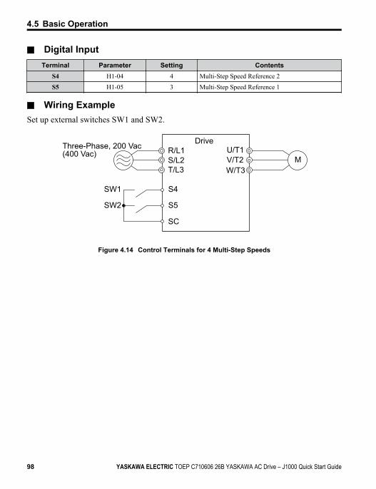
n Digital InputTerminal Parameter Setting Contents
S4 H1-04 4 Multi-Step Speed Reference 2
S5 H1-05 3 Multi-Step Speed Reference 1
n Wiring ExampleSet up external switches SW1 and SW2.
R/L1S/L2T/L3
Three-Phase, 200 Vac (400 Vac)
S4
S5
SW1
SW2
SC
U/T1V/T2W/T3
M
Drive
Figure 4.14 Control Terminals for 4 Multi-Step Speeds
4.5 Basic Operation
98 YASKAWA ELECTRIC TOEP C710606 26B YASKAWA AC Drive – J1000 Quick Start Guide
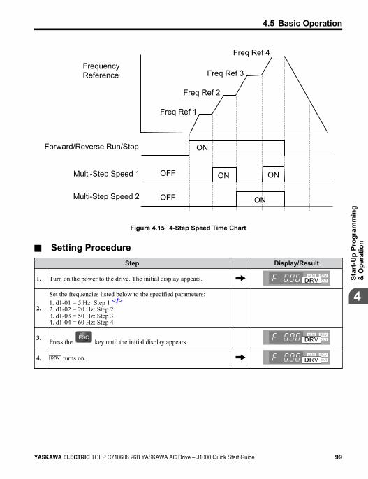
Freq Ref 3
Freq Ref 1
Forward/Reverse Run/Stop
Multi-Step Speed 1
Multi-Step Speed 2
Frequency Reference
Freq Ref 4
Freq Ref 2
ON
ON
ON
OFF
OFF
ON
Figure 4.15 4-Step Speed Time Chart
n Setting ProcedureStep Display/Result
1. Turn on the power to the drive. The initial display appears.
2.
Set the frequencies listed below to the specified parameters:1. d1-01 = 5 Hz: Step 1 <1>2. d1-02 = 20 Hz: Step 23. d1-03 = 50 Hz: Step 34. d1-04 = 60 Hz: Step 4
3. Press the key until the initial display appears.
4. turns on.
4.5 Basic Operation
YASKAWA ELECTRIC TOEP C710606 26B YASKAWA AC Drive – J1000 Quick Start Guide 99
4
Star
t-Up
Prog
ram
min
g&
Ope
ratio
n
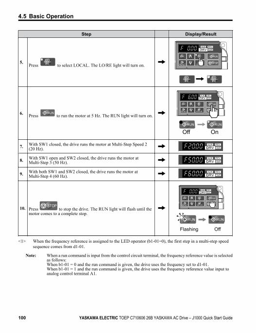
Step Display/Result
5.Press to select LOCAL. The LO/RE light will turn on. STOP
6. Press to run the motor at 5 Hz. The RUN light will turn on.STOP
Off On
7. With SW1 closed, the drive runs the motor at Multi-Step Speed 2(20 Hz).
8. With SW1 open and SW2 closed, the drive runs the motor atMulti-Step 3 (50 Hz).
9. With both SW1 and SW2 closed, the drive runs the motor atMulti-Step 4 (60 Hz).
10. Press STOP
to stop the drive. The RUN light will flash until themotor comes to a complete stop.
STOP
Flashing Off
<1> When the frequency reference is assigned to the LED operator (b1-01=0), the first step in a multi-step speedsequence comes from d1-01.
Note: When a run command is input from the control circuit terminal, the frequency reference value is selectedas follows:When b1-01 = 0 and the run command is given, the drive uses the frequency set to d1-01.When b1-01 = 1 and the run command is given, the drive uses the frequency reference value input toanalog control terminal A1.
4.5 Basic Operation
100 YASKAWA ELECTRIC TOEP C710606 26B YASKAWA AC Drive – J1000 Quick Start Guide
u E1: V/f Characteristics
n E1-01: Input Voltage SettingSet the input voltage parameter to the nominal voltage of the AC power supply. This parameteradjusts the levels of some protective features of the drive (overvoltage, Stall Prevention, etc.).NOTICE: Set parameter E1-01 to match the input voltage of the drive. Drive input voltage (not motor voltage)must be set in E1-01 for the protective features of the drive to function properly. Failure to comply could resultin improper drive operation.
No. Parameter Name Setting Range Default
E1-01 <1> Input Voltage Setting 155 to 255 V 230 V
<1> The setting range and default value shown here are for 200 V class drives. Double this for 400 V class units.
E1-01 Related ValuesThe input voltage setting determines the over-/undervoltage detection level and the operationlevels of the braking transistor.
Voltage Setting Value of E1-01(Approximate Values)
ov DetectionLevel
BTR OperationLevel Uv Detection Level
200 V Class All settings 410 V 394 V 190 V(single-phase = 160 V)
400 V ClassSetting ≥ 400 V 820 V 788 V 380 V
Setting < 400 V 740 V 708 V 350 V
Note: The braking transistor operation levels are valid for the drive internal braking transistor. If an externalCDBR braking chopper is used, refer to the instruction manual of that unit.
n V/f Pattern SettingsThe drive utilizes a set V/f pattern to determine the appropriate output voltage level for eachrelative to the frequency reference.V/f Pattern Setup for V/f Control
1. Set the input voltage for the drive. Refer to E1-01: Input Voltage Setting on page218.
2. Set the V/f pattern. Refer to V/f Pattern Settings E1-04 to E1-10 on page 218.
4.5 Basic Operation
YASKAWA ELECTRIC TOEP C710606 26B YASKAWA AC Drive – J1000 Quick Start Guide 101
4
Star
t-Up
Prog
ram
min
g&
Ope
ratio
n
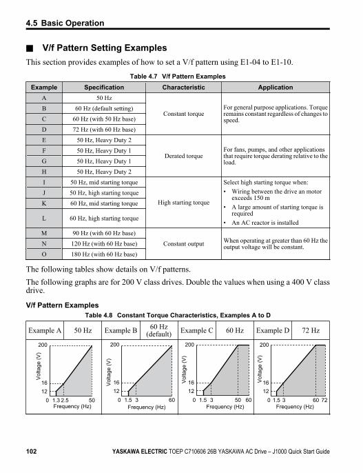
n V/f Pattern Setting ExamplesThis section provides examples of how to set a V/f pattern using E1-04 to E1-10.
Table 4.7 V/f Pattern ExamplesExample Specification Characteristic Application
A 50 Hz
Constant torqueFor general purpose applications. Torqueremains constant regardless of changes tospeed.
B 60 Hz (default setting)
C 60 Hz (with 50 Hz base)
D 72 Hz (with 60 Hz base)
E 50 Hz, Heavy Duty 2
Derated torqueFor fans, pumps, and other applicationsthat require torque derating relative to theload.
F 50 Hz, Heavy Duty 1
G 50 Hz, Heavy Duty 1
H 50 Hz, Heavy Duty 2
I 50 Hz, mid starting torque
High starting torque
Select high starting torque when:• Wiring between the drive an motor
exceeds 150 m• A large amount of starting torque is
required• An AC reactor is installed
J 50 Hz, high starting torque
K 60 Hz, mid starting torque
L 60 Hz, high starting torque
M 90 Hz (with 60 Hz base)
Constant output When operating at greater than 60 Hz theoutput voltage will be constant.N 120 Hz (with 60 Hz base)
O 180 Hz (with 60 Hz base)
The following tables show details on V/f patterns.The following graphs are for 200 V class drives. Double the values when using a 400 V classdrive.
V/f Pattern ExamplesTable 4.8 Constant Torque Characteristics, Examples A to D
Example A 50 Hz Example B 60 Hz(default) Example C 60 Hz Example D 72 Hz
012
200
1.3 2.5 50
16
Vol
tage
(V)
Frequency (Hz)0
1216
200
1.5 3 60
Vol
tage
(V)
Frequency (Hz)0
1216
200
1.5 3 6050
Vol
tage
(V)
Frequency (Hz)0
1216
200
1.5 3 7260
Vol
tage
(V)
Frequency (Hz)
4.5 Basic Operation
102 YASKAWA ELECTRIC TOEP C710606 26B YASKAWA AC Drive – J1000 Quick Start Guide
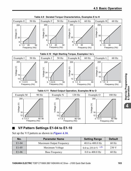
Table 4.9 Derated Torque Characteristics, Examples E to H
Example E 50 Hz Example F 50 Hz Example G 60 Hz Example H 60 Hz
08
200
1.3 25 50
35Volta
ge (V
)
Frequency (Hz)0
9
200
1.3 25 50
50
Vol
tage
(V)
Frequency (Hz)0
8
200
1.5 30 60
35Vol
tage
(V)
Frequency (Hz)0
9
200
1.5 30 60
50
Vol
tage
(V)
Frequency (Hz)
Table 4.10 High Starting Torque, Examples I to L
Example I 50 Hz Example J 50 Hz Example K 60 Hz Example L 60 Hz
012
200
1.3 2.5 50
19Vol
tage
(V)
Frequency (Hz)0
13
200
1.3 2.5 50
24
Vol
tage
(V)
Frequency (Hz)0
12
200
1.5 3 60
19Vol
tage
(V)
Frequency (Hz)0
15
200
1.5 3 60
24
Vol
tage
(V)
Frequency (Hz)
Table 4.11 Rated Output Operation, Examples M to O
Example M 90 Hz Example N 120 Hz Example O 180 Hz
01216
200
1.5 3 9060
Vol
tage
(V)
Frequency (Hz)0
1216
200
1.5 3 12060
Vol
tage
(V)
Frequency (Hz)0
1216
200
1.5 3 18060
Vol
tage
(V)
Frequency (Hz)
n V/f Pattern Settings E1-04 to E1-10Set up the V/f pattern as shown in Figure 4.16.
No. Parameter Name Setting Range DefaultE1-04 Maximum Output Frequency 40.0 to 400.0 Hz 60 Hz
E1-05 Maximum Voltage 0.0 to 255.0 V <1> 230 V
E1-06 Base Frequency 0.0 to 400.0 Hz 60 Hz
4.5 Basic Operation
YASKAWA ELECTRIC TOEP C710606 26B YASKAWA AC Drive – J1000 Quick Start Guide 103
4
Star
t-Up
Prog
ram
min
g&
Ope
ratio
n
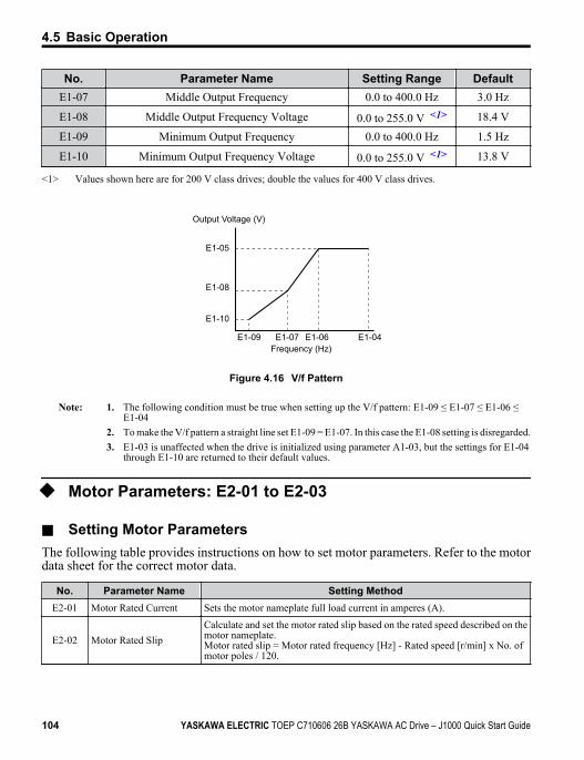
No. Parameter Name Setting Range DefaultE1-07 Middle Output Frequency 0.0 to 400.0 Hz 3.0 Hz
E1-08 Middle Output Frequency Voltage 0.0 to 255.0 V <1> 18.4 V
E1-09 Minimum Output Frequency 0.0 to 400.0 Hz 1.5 Hz
E1-10 Minimum Output Frequency Voltage 0.0 to 255.0 V <1> 13.8 V
<1> Values shown here are for 200 V class drives; double the values for 400 V class drives.
E1-05
E1-08
E1-10
E1-09 E1-07 E1-06 E1-04
Output Voltage (V)
Frequency (Hz)
Figure 4.16 V/f Pattern
Note: 1. The following condition must be true when setting up the V/f pattern: E1-09 ≤ E1-07 ≤ E1-06 ≤E1-04
2. To make the V/f pattern a straight line set E1-09 = E1-07. In this case the E1-08 setting is disregarded.3. E1-03 is unaffected when the drive is initialized using parameter A1-03, but the settings for E1-04
through E1-10 are returned to their default values.
u Motor Parameters: E2-01 to E2-03
n Setting Motor ParametersThe following table provides instructions on how to set motor parameters. Refer to the motordata sheet for the correct motor data.
No. Parameter Name Setting MethodE2-01 Motor Rated Current Sets the motor nameplate full load current in amperes (A).
E2-02 Motor Rated SlipCalculate and set the motor rated slip based on the rated speed described on themotor nameplate.Motor rated slip = Motor rated frequency [Hz] - Rated speed [r/min] x No. ofmotor poles / 120.
4.5 Basic Operation
104 YASKAWA ELECTRIC TOEP C710606 26B YASKAWA AC Drive – J1000 Quick Start Guide
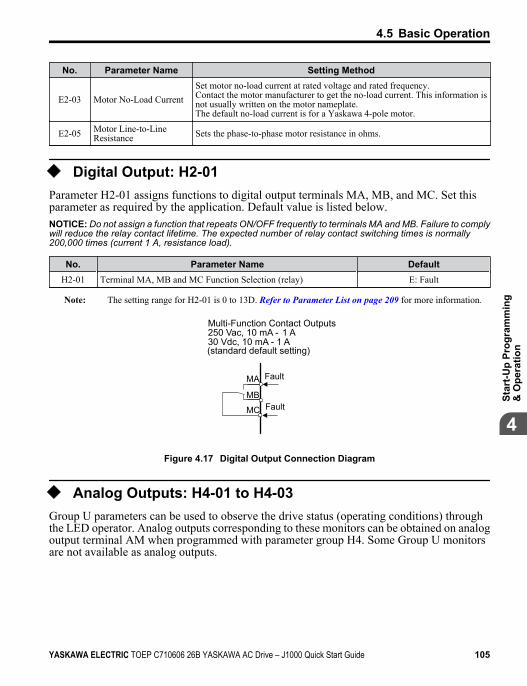
No. Parameter Name Setting Method
E2-03 Motor No-Load CurrentSet motor no-load current at rated voltage and rated frequency.Contact the motor manufacturer to get the no-load current. This information isnot usually written on the motor nameplate.The default no-load current is for a Yaskawa 4-pole motor.
E2-05 Motor Line-to-LineResistance Sets the phase-to-phase motor resistance in ohms.
u Digital Output: H2-01Parameter H2-01 assigns functions to digital output terminals MA, MB, and MC. Set thisparameter as required by the application. Default value is listed below.NOTICE: Do not assign a function that repeats ON/OFF frequently to terminals MA and MB. Failure to complywill reduce the relay contact lifetime. The expected number of relay contact switching times is normally200,000 times (current 1 A, resistance load).
No. Parameter Name DefaultH2-01 Terminal MA, MB and MC Function Selection (relay) E: Fault
Note: The setting range for H2-01 is 0 to 13D. Refer to Parameter List on page 209 for more information.
Multi-Function Contact Outputs250 Vac, 10 mA - 1 A 30 Vdc, 10 mA - 1 A(standard default setting)
MA
MB
MC
Fault
Fault
Figure 4.17 Digital Output Connection Diagram
u Analog Outputs: H4-01 to H4-03Group U parameters can be used to observe the drive status (operating conditions) throughthe LED operator. Analog outputs corresponding to these monitors can be obtained on analogoutput terminal AM when programmed with parameter group H4. Some Group U monitorsare not available as analog outputs.
4.5 Basic Operation
YASKAWA ELECTRIC TOEP C710606 26B YASKAWA AC Drive – J1000 Quick Start Guide 105
4
Star
t-Up
Prog
ram
min
g&
Ope
ratio
n
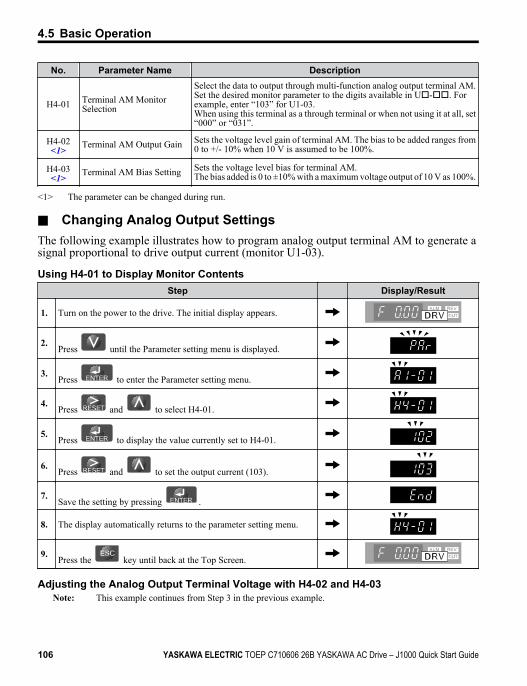
No. Parameter Name Description
H4-01 Terminal AM MonitorSelection
Select the data to output through multi-function analog output terminal AM.Set the desired monitor parameter to the digits available in Uo-oo. Forexample, enter “103” for U1-03.When using this terminal as a through terminal or when not using it at all, set“000” or “031”.
H4-02<1> Terminal AM Output Gain Sets the voltage level gain of terminal AM. The bias to be added ranges from
0 to +/- 10% when 10 V is assumed to be 100%.
H4-03<1> Terminal AM Bias Setting Sets the voltage level bias for terminal AM.
The bias added is 0 to ±10% with a maximum voltage output of 10 V as 100%.
<1> The parameter can be changed during run.
n Changing Analog Output SettingsThe following example illustrates how to program analog output terminal AM to generate asignal proportional to drive output current (monitor U1-03).
Using H4-01 to Display Monitor ContentsStep Display/Result
1. Turn on the power to the drive. The initial display appears.
2.Press until the Parameter setting menu is displayed.
3.Press to enter the Parameter setting menu.
4.Press and to select H4-01.
5.Press to display the value currently set to H4-01.
6.Press and to set the output current (103).
7.Save the setting by pressing .
8. The display automatically returns to the parameter setting menu.
9. Press the key until back at the Top Screen.
Adjusting the Analog Output Terminal Voltage with H4-02 and H4-03Note: This example continues from Step 3 in the previous example.
4.5 Basic Operation
106 YASKAWA ELECTRIC TOEP C710606 26B YASKAWA AC Drive – J1000 Quick Start Guide
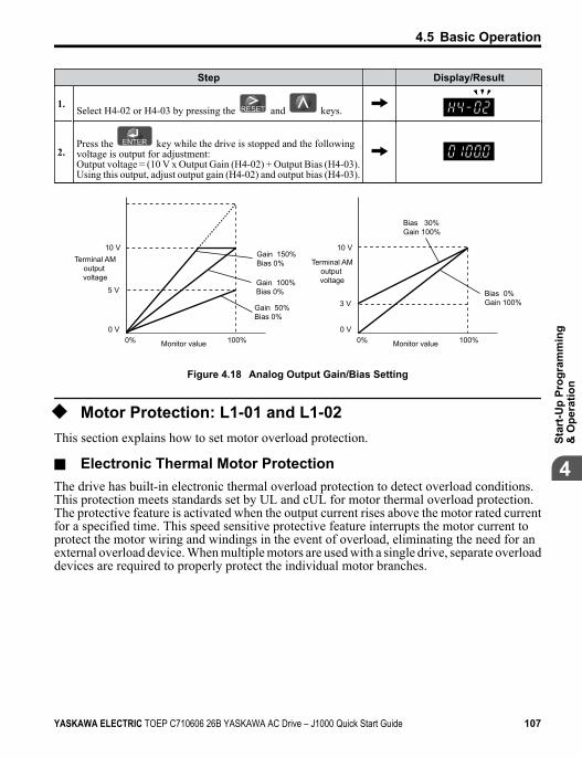
Step Display/Result
1.Select H4-02 or H4-03 by pressing the and keys.
2.Press the key while the drive is stopped and the followingvoltage is output for adjustment:Output voltage = (10 V x Output Gain (H4-02) + Output Bias (H4-03).Using this output, adjust output gain (H4-02) and output bias (H4-03).
0 V
3 V
10 V
Bias 30% Gain 100%
Bias 0% Gain 100%
100%Monitor value0%
Gain 50% Bias 0%
Terminal AM output voltage
0 V
5 V
10 VGain 150% Bias 0%
Gain 100% Bias 0%
100%Monitor value0%
Terminal AM output voltage
Figure 4.18 Analog Output Gain/Bias Setting
u Motor Protection: L1-01 and L1-02This section explains how to set motor overload protection.
n Electronic Thermal Motor ProtectionThe drive has built-in electronic thermal overload protection to detect overload conditions.This protection meets standards set by UL and cUL for motor thermal overload protection.The protective feature is activated when the output current rises above the motor rated currentfor a specified time. This speed sensitive protective feature interrupts the motor current toprotect the motor wiring and windings in the event of overload, eliminating the need for anexternal overload device. When multiple motors are used with a single drive, separate overloaddevices are required to properly protect the individual motor branches.
4.5 Basic Operation
YASKAWA ELECTRIC TOEP C710606 26B YASKAWA AC Drive – J1000 Quick Start Guide 107
4
Star
t-Up
Prog
ram
min
g&
Ope
ratio
n
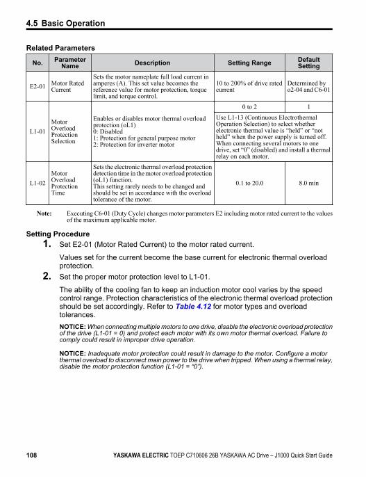
Related Parameters
No. ParameterName Description Setting Range Default
Setting
E2-01 Motor RatedCurrent
Sets the motor nameplate full load current inamperes (A). This set value becomes thereference value for motor protection, torquelimit, and torque control.
10 to 200% of drive ratedcurrent
Determined byo2-04 and C6-01
L1-01MotorOverloadProtectionSelection
Enables or disables motor thermal overloadprotection (oL1)0: Disabled1: Protection for general purpose motor2: Protection for inverter motor
0 to 2 1
Use L1-13 (Continuous ElectrothermalOperation Selection) to select whetherelectronic thermal value is “held” or “notheld” when the power supply is turned off.When connecting several motors to onedrive, set “0” (disabled) and install a thermalrelay on each motor.
L1-02MotorOverloadProtectionTime
Sets the electronic thermal overload protectiondetection time in the motor overload protection(oL1) function.This setting rarely needs to be changed andshould be set in accordance with the overloadtolerance of the motor.
0.1 to 20.0 8.0 min
Note: Executing C6-01 (Duty Cycle) changes motor parameters E2 including motor rated current to the valuesof the maximum applicable motor.
Setting Procedure1. Set E2-01 (Motor Rated Current) to the motor rated current.
Values set for the current become the base current for electronic thermal overloadprotection.
2. Set the proper motor protection level to L1-01.
The ability of the cooling fan to keep an induction motor cool varies by the speedcontrol range. Protection characteristics of the electronic thermal overload protectionshould be set accordingly. Refer to Table 4.12 for motor types and overloadtolerances.NOTICE: When connecting multiple motors to one drive, disable the electronic overload protectionof the drive (L1-01 = 0) and protect each motor with its own motor thermal overload. Failure tocomply could result in improper drive operation.
NOTICE: Inadequate motor protection could result in damage to the motor. Configure a motorthermal overload to disconnect main power to the drive when tripped. When using a thermal relay,disable the motor protection function (L1-01 = “0”).
4.5 Basic Operation
108 YASKAWA ELECTRIC TOEP C710606 26B YASKAWA AC Drive – J1000 Quick Start Guide
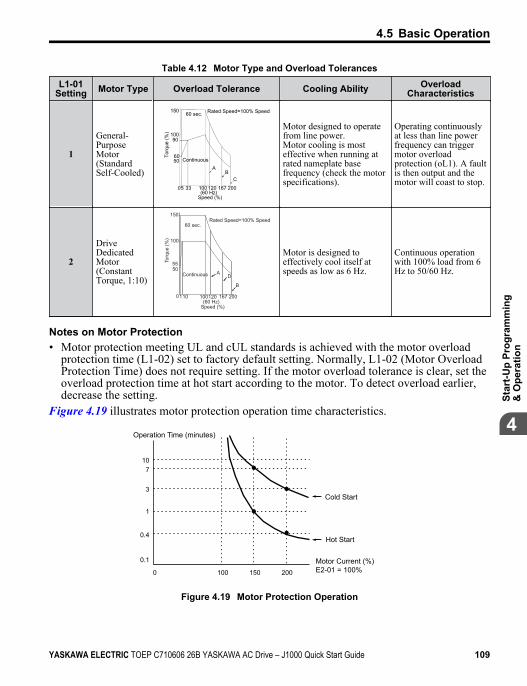
Table 4.12 Motor Type and Overload TolerancesL1-01
Setting Motor Type Overload Tolerance Cooling Ability OverloadCharacteristics
1
General-PurposeMotor(StandardSelf-Cooled)
Motor designed to operatefrom line power.Motor cooling is mosteffective when running atrated nameplate basefrequency (check the motorspecifications).
Operating continuouslyat less than line powerfrequency can triggermotor overloadprotection (oL1). A faultis then output and themotor will coast to stop.
2
DriveDedicatedMotor(ConstantTorque, 1:10)
100
150
110 100120 167 200
5550
0
Rated Speed=100% Speed60 sec.
Continuous AD
B
(60 Hz)Speed (%)
Torq
ue (%
)
Motor is designed toeffectively cool itself atspeeds as low as 6 Hz.
Continuous operationwith 100% load from 6Hz to 50/60 Hz.
Notes on Motor Protection• Motor protection meeting UL and cUL standards is achieved with the motor overload
protection time (L1-02) set to factory default setting. Normally, L1-02 (Motor OverloadProtection Time) does not require setting. If the motor overload tolerance is clear, set theoverload protection time at hot start according to the motor. To detect overload earlier,decrease the setting.
Figure 4.19 illustrates motor protection operation time characteristics.
107
3
1
0.4
0.1
0 100 200150
Cold Start
Hot Start
Motor Current (%)E2-01 = 100%
Operation Time (minutes)
Figure 4.19 Motor Protection Operation
4.5 Basic Operation
YASKAWA ELECTRIC TOEP C710606 26B YASKAWA AC Drive – J1000 Quick Start Guide 109
4
Star
t-Up
Prog
ram
min
g&
Ope
ratio
n
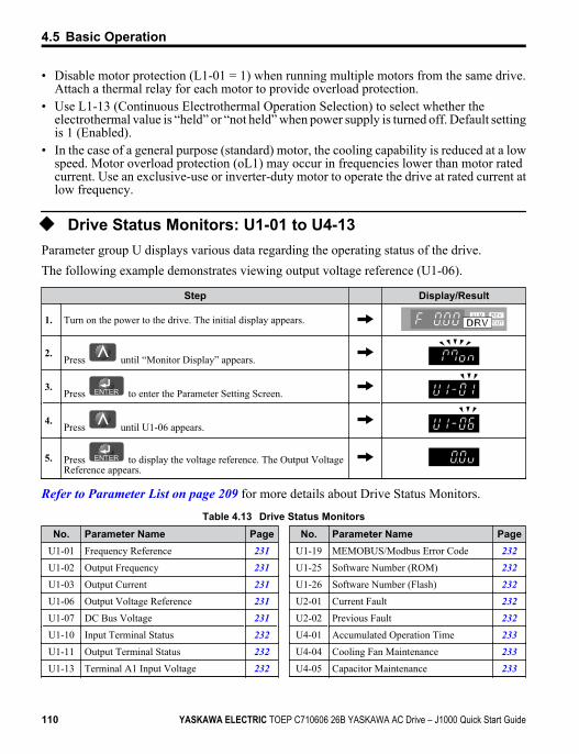
• Disable motor protection (L1-01 = 1) when running multiple motors from the same drive.Attach a thermal relay for each motor to provide overload protection.
• Use L1-13 (Continuous Electrothermal Operation Selection) to select whether theelectrothermal value is “held” or “not held” when power supply is turned off. Default settingis 1 (Enabled).
• In the case of a general purpose (standard) motor, the cooling capability is reduced at a lowspeed. Motor overload protection (oL1) may occur in frequencies lower than motor ratedcurrent. Use an exclusive-use or inverter-duty motor to operate the drive at rated current atlow frequency.
u Drive Status Monitors: U1-01 to U4-13Parameter group U displays various data regarding the operating status of the drive.The following example demonstrates viewing output voltage reference (U1-06).
Step Display/Result
1. Turn on the power to the drive. The initial display appears.
2.Press until “Monitor Display” appears.
3.Press to enter the Parameter Setting Screen.
4.Press until U1-06 appears.
5. Press to display the voltage reference. The Output VoltageReference appears.
Refer to Parameter List on page 209 for more details about Drive Status Monitors.
Table 4.13 Drive Status MonitorsNo. Parameter Name Page
U1-01 Frequency Reference 231U1-02 Output Frequency 231U1-03 Output Current 231U1-06 Output Voltage Reference 231U1-07 DC Bus Voltage 231U1-10 Input Terminal Status 232U1-11 Output Terminal Status 232U1-13 Terminal A1 Input Voltage 232
No. Parameter Name PageU1-19 MEMOBUS/Modbus Error Code 232U1-25 Software Number (ROM) 232U1-26 Software Number (Flash) 232U2-01 Current Fault 232U2-02 Previous Fault 232U4-01 Accumulated Operation Time 233U4-04 Cooling Fan Maintenance 233U4-05 Capacitor Maintenance 233
4.5 Basic Operation
110 YASKAWA ELECTRIC TOEP C710606 26B YASKAWA AC Drive – J1000 Quick Start Guide
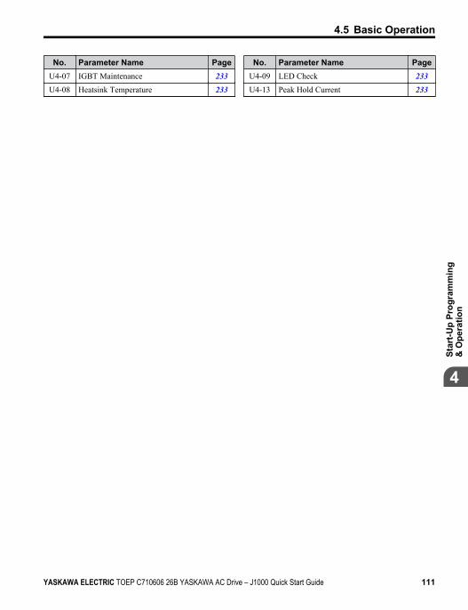
No. Parameter Name PageU4-07 IGBT Maintenance 233U4-08 Heatsink Temperature 233
No. Parameter Name PageU4-09 LED Check 233U4-13 Peak Hold Current 233
4.5 Basic Operation
YASKAWA ELECTRIC TOEP C710606 26B YASKAWA AC Drive – J1000 Quick Start Guide 111
4
Star
t-Up
Prog
ram
min
g&
Ope
ratio
n
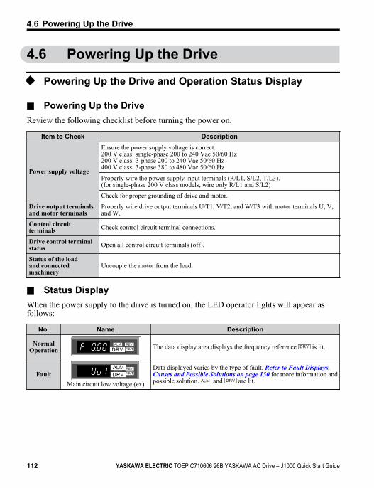
4.6 Powering Up the Drive
u Powering Up the Drive and Operation Status Display
n Powering Up the DriveReview the following checklist before turning the power on.
Item to Check Description
Power supply voltage
Ensure the power supply voltage is correct:200 V class: single-phase 200 to 240 Vac 50/60 Hz200 V class: 3-phase 200 to 240 Vac 50/60 Hz400 V class: 3-phase 380 to 480 Vac 50/60 Hz
Properly wire the power supply input terminals (R/L1, S/L2, T/L3).(for single-phase 200 V class models, wire only R/L1 and S/L2)
Check for proper grounding of drive and motor.
Drive output terminalsand motor terminals
Properly wire drive output terminals U/T1, V/T2, and W/T3 with motor terminals U, V,and W.
Control circuitterminals Check control circuit terminal connections.
Drive control terminalstatus Open all control circuit terminals (off).
Status of the loadand connectedmachinery
Uncouple the motor from the load.
n Status DisplayWhen the power supply to the drive is turned on, the LED operator lights will appear asfollows:
No. Name Description
NormalOperation
STOP
The data display area displays the frequency reference. is lit.
Fault
STOP
Main circuit low voltage (ex)
Data displayed varies by the type of fault. Refer to Fault Displays, Causes and Possible Solutions on page 130 for more information andpossible solution. and are lit.
4.6 Powering Up the Drive
112 YASKAWA ELECTRIC TOEP C710606 26B YASKAWA AC Drive – J1000 Quick Start Guide
u V/f Pattern SettingSetting the V/f pattern according to the application. for details on setting the V/f pattern.
n Notes when Setting the V/f PatternSet the maximum output frequency to match the motor characteristics.If the V/f pattern voltage is increased motor torque may also increase. However, if the V/fvoltage is set too high these problems may occur:• Excessive motor current.• Motor overheat or vibration.
4.6 Powering Up the Drive
YASKAWA ELECTRIC TOEP C710606 26B YASKAWA AC Drive – J1000 Quick Start Guide 113
4
Star
t-Up
Prog
ram
min
g&
Ope
ratio
n
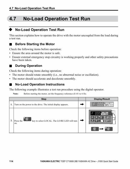
4.7 No-Load Operation Test Run
u No-Load Operation Test RunThis section explains how to operate the drive with the motor uncoupled from the load duringa test run.
n Before Starting the MotorCheck the following items before operation:• Ensure the area around the motor is safe.• Ensure external emergency stop circuitry is working properly and other safety precautions
have been taken.
n During OperationCheck the following items during operation:• The motor should rotate smoothly (i.e., no abnormal noise or oscillation).• The motor should accelerate and decelerate smoothly.
n No-Load Operation InstructionsThe following example illustrates a test run procedure using the digital operator.
Note: Before starting the motor, set the frequency reference d1-01 to 6 Hz.
Step Display/Result
1. Turn on the power to the drive. The initial display appears.
2. Press the key to select LOCAL. The LO/RE LED will turnon.
STOP
4.7 No-Load Operation Test Run
114 YASKAWA ELECTRIC TOEP C710606 26B YASKAWA AC Drive – J1000 Quick Start Guide
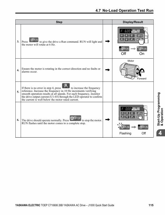
Step Display/Result
3. Press to give the drive a Run command. RUN will light andthe motor will rotate at 6 Hz.
STOP
Off On
4. Ensure the motor is rotating in the correct direction and no faults oralarms occur.
Motor
Forward
5.If there is no error in step 4, press to increase the frequencyreference. Increase the frequency in 10 Hz increments verifyingsmooth operation results at all speeds. For each frequency, monitorthe drive output current (U1-03) through the LED operator to confirmthe current is well below the motor rated current.
6. The drive should operate normally. Press STOP
to stop the motor.RUN flashes until the motor comes to a complete stop.
STOP
Flashing Off
4.7 No-Load Operation Test Run
YASKAWA ELECTRIC TOEP C710606 26B YASKAWA AC Drive – J1000 Quick Start Guide 115
4
Star
t-Up
Prog
ram
min
g&
Ope
ratio
n
4.8 Test Run with Load Connected
u Test Run with the Load ConnectedAfter performing a no-load test run connect the load and proceed to run the motor and loadtogether.
n Notes on Connected Machinery• Clear the area around the motor.• The motor should come to a complete stop without problems.• Connect the machinery.• Fasten all installation screws properly. Check that the motor and connected machinery are
held in place.• Confirm that the Fast-stop circuit or mechanical safety measures operate correctly.• Be ready to press the STOP button in case of emergency.
n Checklist Before Operation• The motor should rotate in the proper direction.• The motor should accelerate and decelerate smoothly.
n Operating the Motor under Loaded ConditionsTest run the application similarly to the no-load test procedure when connecting the machineryto the motor.• Check monitor parameter U1-03 to ensure there is no overcurrent.• If the application permits running the load in the reverse direction, try changing motor
direction and the frequency reference while watching for abnormal motor oscillation orvibration.
• Correct any problems that occurs with hunting, oscillation, or other control-related issues.
4.8 Test Run with Load Connected
116 YASKAWA ELECTRIC TOEP C710606 26B YASKAWA AC Drive – J1000 Quick Start Guide
4.9 Verifying and Backing Up ParameterSettings
Check changes to parameter settings using the Verify function. Refer to Verifying Parameter Changes: Verify Menu on page 84.Save the verified parameter settings. Change the access level or set a password to the drive toprevent accidental modification of parameter settings.
u Parameter Access Level: A1-01Setting the Access Level for “Operation only” (A1-01 = 0) allows the user to access parametersA1-oo and Uo-oo only. Other parameters are not displayed.
No. ParameterName Description Setting
Range Default
A1-01 Access LevelSelection
Selects which parameters are accessible via the digital operator.0: Operation only (A1-01 and A1-04 can be set and monitored. Uparameters can be monitored)2: Advanced Access Level (All parameters can be set and monitored)
0, 2 2
u Password Settings: A1-04, A1-05The user can set a password to the drive to restrict access. The password is selected viaparameter A1-05. The selected password must be entered in parameter A1-04 to unlockparameter access (i.e., parameter setting A1-04 must match the value programmed intoA1-05). The following parameters cannot be viewed or edited until the value programmedinto A1-04 correctly matches the value as programmed in parameter A1-05: A1-01 and A1-03.
Note: Parameter A1-05 is hidden from view. To display A1-05, access parameter A1-04 and simultaneously
depress the key and the key.
u Copy Function (Optional)Parameter settings can be copied to another drive to simplify parameter restoration or multipledrive setup. The RS-232C Interface Unit (Removable Type) (SI-232/JC) is required to usethe following options with J1000 drives:
n USB/Copy Unit (JVOP-181)The copy unit is an external option connected to the drive to copy parameter settings to anotherdrive. It includes a USB adapter to connect the drive to a PC.
4.9 Verifying and Backing Up Parameter Settings
YASKAWA ELECTRIC TOEP C710606 26B YASKAWA AC Drive – J1000 Quick Start Guide 117
4
Star
t-Up
Prog
ram
min
g&
Ope
ratio
n
n LED Operator (JVOP-182)The LED operator operates the drive and supports copying, importing, and verifying parametersettings.
Note: Use of the LED operator requires that the drive is running drive software version PRG: 1010 or later.
n Drive Wizard PlusDrive Wizard Plus is a PC software tool for parameter management, monitoring, anddiagnosis. Drive Wizard Plus can load, store, and copy drive parameter settings. For details,refer to Help in the Drive Wizard Plus software.The installation files can be obtained at no charge from:U.S.: http://www.yaskawa.com
4.9 Verifying and Backing Up Parameter Settings
118 YASKAWA ELECTRIC TOEP C710606 26B YASKAWA AC Drive – J1000 Quick Start Guide
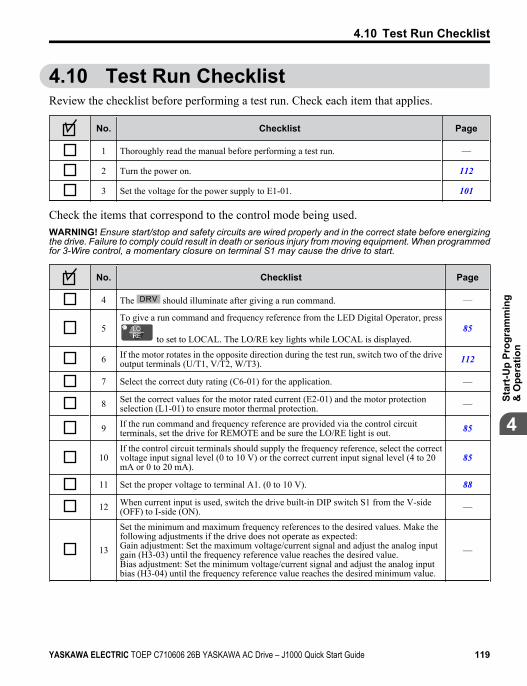
4.10 Test Run ChecklistReview the checklist before performing a test run. Check each item that applies.
No. Checklist Page
1 Thoroughly read the manual before performing a test run. —
2 Turn the power on. 112
3 Set the voltage for the power supply to E1-01. 101
Check the items that correspond to the control mode being used.WARNING! Ensure start/stop and safety circuits are wired properly and in the correct state before energizingthe drive. Failure to comply could result in death or serious injury from moving equipment. When programmedfor 3-Wire control, a momentary closure on terminal S1 may cause the drive to start.
No. Checklist Page
4 The should illuminate after giving a run command. —
5To give a run command and frequency reference from the LED Digital Operator, press
to set to LOCAL. The LO/RE key lights while LOCAL is displayed.85
6 If the motor rotates in the opposite direction during the test run, switch two of the driveoutput terminals (U/T1, V/T2, W/T3). 112
7 Select the correct duty rating (C6-01) for the application. —
8 Set the correct values for the motor rated current (E2-01) and the motor protectionselection (L1-01) to ensure motor thermal protection. —
9 If the run command and frequency reference are provided via the control circuitterminals, set the drive for REMOTE and be sure the LO/RE light is out. 85
10If the control circuit terminals should supply the frequency reference, select the correctvoltage input signal level (0 to 10 V) or the correct current input signal level (4 to 20mA or 0 to 20 mA).
85
11 Set the proper voltage to terminal A1. (0 to 10 V). 88
12 When current input is used, switch the drive built-in DIP switch S1 from the V-side(OFF) to I-side (ON). —
13
Set the minimum and maximum frequency references to the desired values. Make thefollowing adjustments if the drive does not operate as expected:Gain adjustment: Set the maximum voltage/current signal and adjust the analog inputgain (H3-03) until the frequency reference value reaches the desired value.Bias adjustment: Set the minimum voltage/current signal and adjust the analog inputbias (H3-04) until the frequency reference value reaches the desired minimum value.
—
4.10 Test Run Checklist
YASKAWA ELECTRIC TOEP C710606 26B YASKAWA AC Drive – J1000 Quick Start Guide 119
4
Star
t-Up
Prog
ram
min
g&
Ope
ratio
n
4.10 Test Run Checklist
This Page Intentionally Blank
120 YASKAWA ELECTRIC TOEP C710606 26B YASKAWA AC Drive – J1000 Quick Start Guide
TroubleshootingThis chapter provides descriptions of the drive faults, alarms,errors, related displays, and possible solutions. This chapter canalso serve as a reference guide for tuning the drive during a trialrun.
5.1 SECTION SAFETY...........................................1225.2 MOTOR PERFORMANCE FINE TUNING..........1255.3 DRIVE ALARMS, FAULTS, AND ERRORS.......1275.4 FAULT DETECTION........................................ 1305.5 ALARM DETECTION.......................................1405.6 OPERATOR PROGRAMMING ERRORS.......... 1455.7 DIAGNOSING AND RESETTING FAULTS........1475.8 TROUBLESHOOTING WITHOUT FAULT
DISPLAY.........................................................149
5
YASKAWA ELECTRIC TOEP C710606 26B YASKAWA AC Drive – J1000 Quick Start Guide 121

5.1 Section Safety
DANGER
Electrical Shock HazardDo not connect or disconnect wiring while the power is on.Failure to comply will result in death or serious injury.
WARNING
Electrical Shock HazardDo not operate equipment with covers removed.Failure to comply could result in death or serious injury.The diagrams in this section may illustrate drives without covers or safety shields to displaydetails. Be sure to reinstall covers or shields before operating the drives and run the drivesaccording to the instructions described in this manual.Always ground the motor-side grounding terminal.Improper equipment grounding could result in death or serious injury by contacting themotor case.Do not touch terminals before the capacitors have fully discharged.Failure to comply could result in death or serious injury.Before wiring terminals, disconnect all power to the equipment. The internal capacitorremains charged even after the drive input power is turned off. The charge indicator LEDwill extinguish when the DC bus voltage is below 50 Vdc. To prevent electric shock, waitat least one minute after all indicators are off and measure the DC bus voltage level to confirmsafe level.Do not allow unqualified personnel to perform work on the drive.Failure to comply could result in death or serious injury.Installation, maintenance, inspection and servicing must be performed only by authorizedpersonnel familiar with installation, adjustment and maintenance of AC drives.
5.1 Section Safety
122 YASKAWA ELECTRIC TOEP C710606 26B YASKAWA AC Drive – J1000 Quick Start Guide
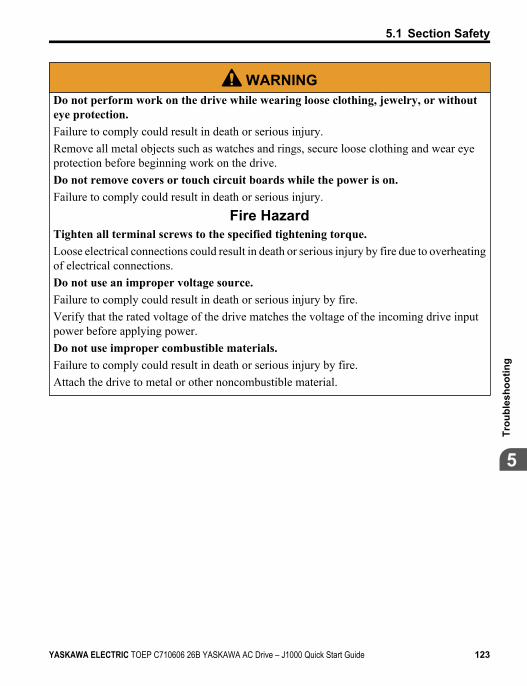
WARNINGDo not perform work on the drive while wearing loose clothing, jewelry, or withouteye protection.Failure to comply could result in death or serious injury.Remove all metal objects such as watches and rings, secure loose clothing and wear eyeprotection before beginning work on the drive.Do not remove covers or touch circuit boards while the power is on.Failure to comply could result in death or serious injury.
Fire HazardTighten all terminal screws to the specified tightening torque.Loose electrical connections could result in death or serious injury by fire due to overheatingof electrical connections.Do not use an improper voltage source.Failure to comply could result in death or serious injury by fire.Verify that the rated voltage of the drive matches the voltage of the incoming drive inputpower before applying power.Do not use improper combustible materials.Failure to comply could result in death or serious injury by fire.Attach the drive to metal or other noncombustible material.
5.1 Section Safety
YASKAWA ELECTRIC TOEP C710606 26B YASKAWA AC Drive – J1000 Quick Start Guide 123
5
Trou
bles
hoot
ing
NOTICE
Observe proper electrostatic discharge procedures (ESD) when handling the drive andcircuit boards.Failure to comply may result in ESD damage to the drive circuitry.Never connect or disconnect the motor from the drive while the drive is outputtingvoltage.Improper equipment sequencing could result in damage to the drive.Do not use unshielded cable for control wiring.Failure to comply may cause electrical interference resulting in poor system performance.Use shielded twisted-pair wires and ground the shield to the ground terminal of the drive.Do not allow unqualified personnel to use the product.Failure to comply could result in damage to the drive or braking circuit.Carefully review instruction manual TOBPC72060000 when connecting a braking optionto the drive.Do not modify the drive circuitry.Failure to comply could result in damage to the drive and will void warranty.Yaskawa is not responsible for modification of the product made by the user.Check all the wiring after installing the drive and connecting other devices to ensurethat all connections are correct.Failure to comply could result in damage to the drive.
5.1 Section Safety
124 YASKAWA ELECTRIC TOEP C710606 26B YASKAWA AC Drive – J1000 Quick Start Guide
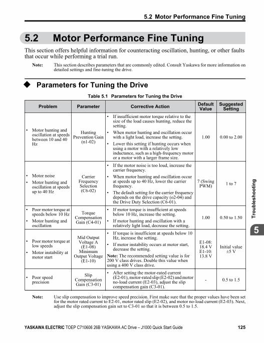
5.2 Motor Performance Fine TuningThis section offers helpful information for counteracting oscillation, hunting, or other faultsthat occur while performing a trial run.
Note: This section describes parameters that are commonly edited. Consult Yaskawa for more information ondetailed settings and fine-tuning the drive.
u Parameters for Tuning the DriveTable 5.1 Parameters for Tuning the Drive
Problem Parameter Corrective Action DefaultValue
SuggestedSetting
• Motor hunting andoscillation at speedsbetween 10 and 40Hz
HuntingPrevention Gain
(n1-02)
• If insufficient motor torque relative to thesize of the load causes hunting, reduce thesetting.
• When motor hunting and oscillation occurwith a light load, increase the setting.
• Lower this setting if hunting occurs whenusing a motor with a relatively lowinductance, such as a high-frequency motoror a motor with a larger frame size.
1.00 0.00 to 2.00
• Motor noise• Motor hunting and
oscillation at speedsup to 40 Hz
CarrierFrequencySelection(C6-02)
• If the motor noise is too loud, increase thecarrier frequency.
• When motor hunting and oscillation occurat speeds up to 40 Hz, lower the carrierfrequency.
• The default setting for the carrier frequencydepends on the drive capacity (o2-04) andthe Drive Duty Selection (C6-01).
7 (SwingPWM) 1 to 7
• Poor motor torque atspeeds below 10 Hz
• Motor hunting andoscillation
TorqueCompensationGain (C4-01)
• If motor torque is insufficient at speedsbelow 10 Hz, increase the setting.
• If motor hunting and oscillation with arelatively light load, decrease the setting.
1.00 0.50 to 1.50
• Poor motor torque atlow speeds
• Motor instability atmotor start
Mid OutputVoltage A
(E1-08)Minimum
Output Voltage(E1-10)
• If torque is insufficient at speeds below 10Hz, increase the setting.
• If motor instability occurs at motor start,decrease the setting.
Note: The recommended setting value is for200 V class drives. Double this value whenusing a 400 V class drive.
E1-08:18.4 VE1-10:13.8 V
Initial value±5 V
• Poor speedprecision
SlipCompensationGain (C3-01)
• After setting the motor-rated current(E2-01), motor-rated slip (E2-02) and motorno-load current (E2-03), adjust the slipcompensation gain (C3-01).
- 0.5 to 1.5
Note: Use slip compensation to improve speed precision. First make sure that the proper values have been setfor the motor rated current to E2-01, motor rated slip (E2-02), and motor no-load current (E2-03). Next,adjust the slip compensation gain set to C3-01 so that it is between 0.5 to 1.5.
5.2 Motor Performance Fine Tuning
YASKAWA ELECTRIC TOEP C710606 26B YASKAWA AC Drive – J1000 Quick Start Guide 125
5
Trou
bles
hoot
ing
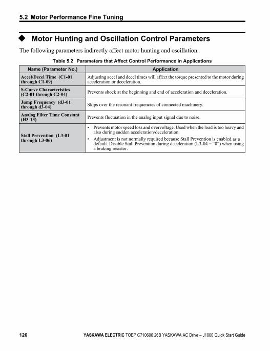
u Motor Hunting and Oscillation Control ParametersThe following parameters indirectly affect motor hunting and oscillation.
Table 5.2 Parameters that Affect Control Performance in ApplicationsName (Parameter No.) Application
Accel/Decel Time (C1-01through C1-09)
Adjusting accel and decel times will affect the torque presented to the motor duringacceleration or deceleration.
S-Curve Characteristics(C2-01 through C2-04) Prevents shock at the beginning and end of acceleration and deceleration.
Jump Frequency (d3-01through d3-04) Skips over the resonant frequencies of connected machinery.
Analog Filter Time Constant(H3-13) Prevents fluctuation in the analog input signal due to noise.
Stall Prevention (L3-01through L3-06)
• Prevents motor speed loss and overvoltage. Used when the load is too heavy andalso during sudden acceleration/deceleration.
• Adjustment is not normally required because Stall Prevention is enabled as adefault. Disable Stall Prevention during deceleration (L3-04 = “0”) when usinga braking resistor.
5.2 Motor Performance Fine Tuning
126 YASKAWA ELECTRIC TOEP C710606 26B YASKAWA AC Drive – J1000 Quick Start Guide
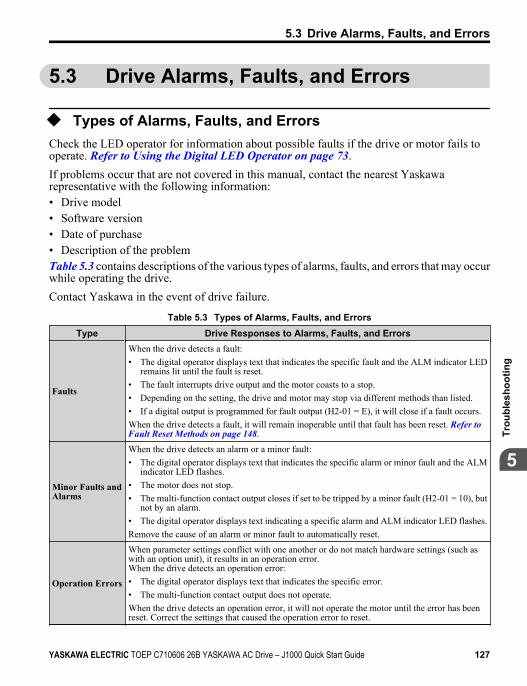
5.3 Drive Alarms, Faults, and Errors
u Types of Alarms, Faults, and ErrorsCheck the LED operator for information about possible faults if the drive or motor fails tooperate. Refer to Using the Digital LED Operator on page 73.If problems occur that are not covered in this manual, contact the nearest Yaskawarepresentative with the following information:• Drive model• Software version• Date of purchase• Description of the problemTable 5.3 contains descriptions of the various types of alarms, faults, and errors that may occurwhile operating the drive.Contact Yaskawa in the event of drive failure.
Table 5.3 Types of Alarms, Faults, and ErrorsType Drive Responses to Alarms, Faults, and Errors
Faults
When the drive detects a fault:• The digital operator displays text that indicates the specific fault and the ALM indicator LED
remains lit until the fault is reset.• The fault interrupts drive output and the motor coasts to a stop.• Depending on the setting, the drive and motor may stop via different methods than listed.• If a digital output is programmed for fault output (H2-01 = E), it will close if a fault occurs.When the drive detects a fault, it will remain inoperable until that fault has been reset. Refer to Fault Reset Methods on page 148.
Minor Faults andAlarms
When the drive detects an alarm or a minor fault:• The digital operator displays text that indicates the specific alarm or minor fault and the ALM
indicator LED flashes.• The motor does not stop.• The multi-function contact output closes if set to be tripped by a minor fault (H2-01 = 10), but
not by an alarm.• The digital operator displays text indicating a specific alarm and ALM indicator LED flashes.Remove the cause of an alarm or minor fault to automatically reset.
Operation Errors
When parameter settings conflict with one another or do not match hardware settings (such aswith an option unit), it results in an operation error.When the drive detects an operation error:• The digital operator displays text that indicates the specific error.• The multi-function contact output does not operate.When the drive detects an operation error, it will not operate the motor until the error has beenreset. Correct the settings that caused the operation error to reset.
5.3 Drive Alarms, Faults, and Errors
YASKAWA ELECTRIC TOEP C710606 26B YASKAWA AC Drive – J1000 Quick Start Guide 127
5
Trou
bles
hoot
ing
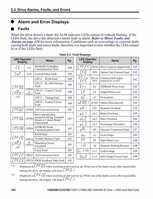
u Alarm and Error Displays
n FaultsWhen the drive detects a fault, the ALM indicator LEDs remain lit without flashing. If theLEDs flash, the drive has detected a minor fault or alarm. Refer to Minor Faults and Alarms on page 129 for more information. Conditions such as overvoltage or external faultscan trip both faults and minor faults, therefore it is important to note whether the LEDs remainlit or if the LEDs flash.
Table 5.4 Fault DisplaysLED Operator
Display Name Pg.
CE MEMOBUS/ModbusCommunication Error 130
CoF Current Offset Fault 130
or
<1>
CPF00or
CPF01
CPF11 – RAM Fault 130CPF12 – FLASH MemoryFault 130
CPF14 – Control CircuitFault 130
CPF17 – Timing Fault 130CPF18 – Control CircuitFault 130
CPF02 A/D Conversion Error 131
CPF06Drive specificationmismatch during TerminalBoard or Control Boardreplacement
131
CPF08 EEPROM SerialCommunications Fault 131
or
<2>
CPF20or
CPF21
RAM Fault 131FLASH Memory Fault 131Watchdog CircuitException 131
Clock Fault 131
CPF22 A/D Conversion Error 132
CPF23 PWM Feedback Data Fault 132
LED OperatorDisplay Name Pg.
CPF24 Drive Capacity Signal Fault 132
EF0 Option Unit External Fault 132
to EF1 toEF5
External Fault (inputterminal S1 to S5) 132
Err EEPROM Write Error 133
LF Output Phase Loss 133
oC Overcurrent 133
oFA01 Option Disconnected 134
oH1 Heatsink Overheat 135
oL1 Motor Overload 135
oL2 Drive Overload 136
oL3 Overtorque Detection 1 136
oPr Operator Connection Fault 137
ov Overvoltage 143
PF Input Phase Loss 138
rH Dynamic Braking Resistor 138
<3> Uv1 Undervoltage 139
Uv3 Soft Charge Circuit Fault 139
<1> Displayed as when occurring at drive power up. When one of the faults occurs after successfullystarting the drive, the display will show .
<2> Displayed as when occurring at drive power up. When one of the faults occurs after successfullystarting the drive, the display will show .
5.3 Drive Alarms, Faults, and Errors
128 YASKAWA ELECTRIC TOEP C710606 26B YASKAWA AC Drive – J1000 Quick Start Guide
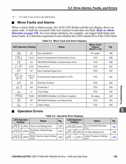
<3> Uv1 fault is not saved to the fault history
n Minor Faults and AlarmsWhen a minor fault or alarm occurs, the ALM LED flashes and the text display shows analarm code. A fault has occurred if the text remains lit and does not flash. Refer to Alarm Detection on page 140. An overvoltage situation, for example, can trigger both faults andminor faults. It is therefore important to note whether the LEDs remain lit or if the LEDs flash.
Table 5.5 Minor Fault and Alarm Displays
LED Operator Display NameMinor Fault
Output(H2-01 = 10)
Pg.
bb Drive Baseblock No output 140
CALL Serial Communication Transmission Error YES 140
CE MEMOBUS/Modbus Communication Error YES 140
CrST Cannot Reset YES 141
EF Run Command Input Error YES 141
to EF1 toEF5 External Fault (input terminal S1 to S5) YES 141
oH Heatsink Overheat YES 142
oL3 Overtorque 1 YES 143
ov Overvoltage YES 143
PASS MEMOBUS/Modbus Test Mode Complete No output 143
SE MEMOBUS/Modbus Test Mode Fault YES 143
Uv Undervoltage YES 144
n Operation ErrorsTable 5.6 Operation Error Displays
LED OperatorDisplay Name Pg.
oPE01 Drive Unit Setting Error 145
oPE02 Parameter Setting RangeError 145
oPE03 Multi-Function Input SettingError 145
LED OperatorDisplay Name Pg.
oPE05 Run Command SelectionError 146
oPE10 V/f Data Setting Error 146
oPE11 Carrier Frequency SettingError 146
5.3 Drive Alarms, Faults, and Errors
YASKAWA ELECTRIC TOEP C710606 26B YASKAWA AC Drive – J1000 Quick Start Guide 129
5
Trou
bles
hoot
ing
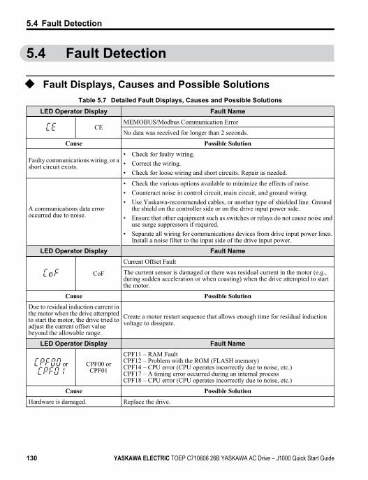
5.4 Fault Detection
u Fault Displays, Causes and Possible SolutionsTable 5.7 Detailed Fault Displays, Causes and Possible Solutions
LED Operator Display Fault Name
CEMEMOBUS/Modbus Communication Error
No data was received for longer than 2 seconds.
Cause Possible Solution
Faulty communications wiring, or ashort circuit exists.
• Check for faulty wiring.• Correct the wiring.• Check for loose wiring and short circuits. Repair as needed.
A communications data erroroccurred due to noise.
• Check the various options available to minimize the effects of noise.• Counteract noise in control circuit, main circuit, and ground wiring.• Use Yaskawa-recommended cables, or another type of shielded line. Ground
the shield on the controller side or on the drive input power side.• Ensure that other equipment such as switches or relays do not cause noise and
use surge suppressors if required.• Separate all wiring for communications devices from drive input power lines.
Install a noise filter to the input side of the drive input power.
LED Operator Display Fault Name
CoF
Current Offset Fault
The current sensor is damaged or there was residual current in the motor (e.g.,during sudden acceleration or when coasting) when the drive attempted to startthe motor.
Cause Possible SolutionDue to residual induction current inthe motor when the drive attemptedto start the motor, the drive tried toadjust the current offset valuebeyond the allowable range.
Create a motor restart sequence that allows enough time for residual inductionvoltage to dissipate.
LED Operator Display Fault Name
or CPF00 orCPF01
CPF11 – RAM FaultCPF12 – Problem with the ROM (FLASH memory)CPF14 – CPU error (CPU operates incorrectly due to noise, etc.)CPF17 – A timing error occurred during an internal processCPF18 – CPU error (CPU operates incorrectly due to noise, etc.)
Cause Possible SolutionHardware is damaged. Replace the drive.
5.4 Fault Detection
130 YASKAWA ELECTRIC TOEP C710606 26B YASKAWA AC Drive – J1000 Quick Start Guide
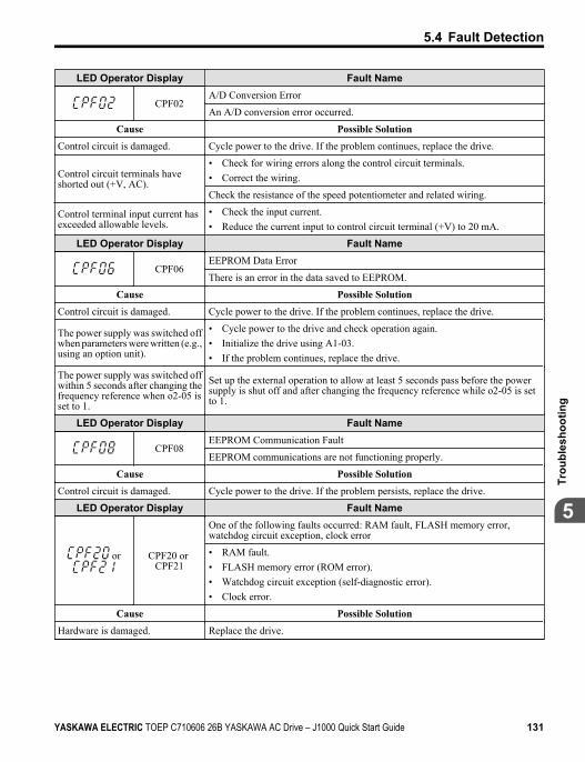
LED Operator Display Fault Name
CPF02A/D Conversion Error
An A/D conversion error occurred.
Cause Possible SolutionControl circuit is damaged. Cycle power to the drive. If the problem continues, replace the drive.
Control circuit terminals haveshorted out (+V, AC).
• Check for wiring errors along the control circuit terminals.• Correct the wiring.
Check the resistance of the speed potentiometer and related wiring.
Control terminal input current hasexceeded allowable levels.
• Check the input current.• Reduce the current input to control circuit terminal (+V) to 20 mA.
LED Operator Display Fault Name
CPF06EEPROM Data Error
There is an error in the data saved to EEPROM.
Cause Possible SolutionControl circuit is damaged. Cycle power to the drive. If the problem continues, replace the drive.
The power supply was switched offwhen parameters were written (e.g.,using an option unit).
• Cycle power to the drive and check operation again.• Initialize the drive using A1-03.• If the problem continues, replace the drive.
The power supply was switched offwithin 5 seconds after changing thefrequency reference when o2-05 isset to 1.
Set up the external operation to allow at least 5 seconds pass before the powersupply is shut off and after changing the frequency reference while o2-05 is setto 1.
LED Operator Display Fault Name
CPF08EEPROM Communication Fault
EEPROM communications are not functioning properly.
Cause Possible SolutionControl circuit is damaged. Cycle power to the drive. If the problem persists, replace the drive.
LED Operator Display Fault Name
or CPF20 or CPF21
One of the following faults occurred: RAM fault, FLASH memory error, watchdog circuit exception, clock error
• RAM fault.• FLASH memory error (ROM error).• Watchdog circuit exception (self-diagnostic error).• Clock error.
Cause Possible SolutionHardware is damaged. Replace the drive.
5.4 Fault Detection
YASKAWA ELECTRIC TOEP C710606 26B YASKAWA AC Drive – J1000 Quick Start Guide 131
5
Trou
bles
hoot
ing
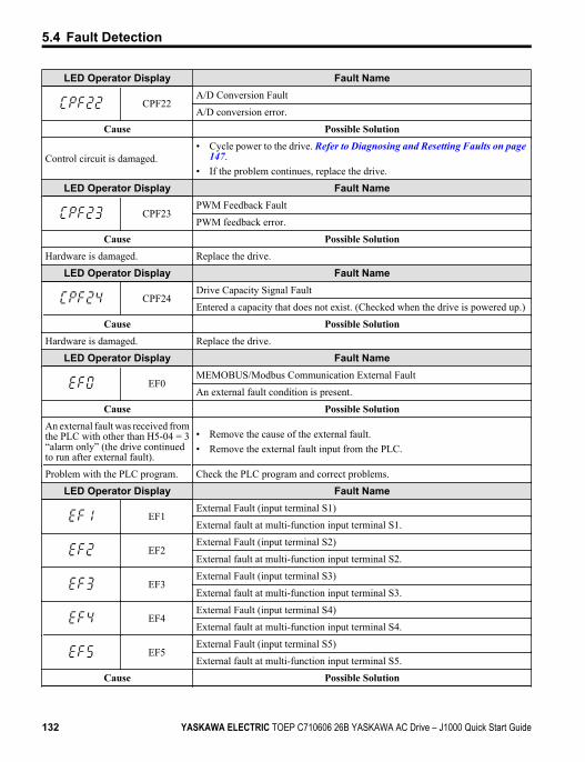
LED Operator Display Fault Name
CPF22A/D Conversion Fault
A/D conversion error.
Cause Possible Solution
Control circuit is damaged.• Cycle power to the drive. Refer to Diagnosing and Resetting Faults on page
147.• If the problem continues, replace the drive.
LED Operator Display Fault Name
CPF23PWM Feedback Fault
PWM feedback error.
Cause Possible SolutionHardware is damaged. Replace the drive.
LED Operator Display Fault Name
CPF24Drive Capacity Signal Fault
Entered a capacity that does not exist. (Checked when the drive is powered up.)
Cause Possible SolutionHardware is damaged. Replace the drive.
LED Operator Display Fault Name
EF0MEMOBUS/Modbus Communication External Fault
An external fault condition is present.
Cause Possible SolutionAn external fault was received fromthe PLC with other than H5-04 = 3“alarm only” (the drive continuedto run after external fault).
• Remove the cause of the external fault.• Remove the external fault input from the PLC.
Problem with the PLC program. Check the PLC program and correct problems.
LED Operator Display Fault Name
EF1External Fault (input terminal S1)
External fault at multi-function input terminal S1.
EF2External Fault (input terminal S2)
External fault at multi-function input terminal S2.
EF3External Fault (input terminal S3)
External fault at multi-function input terminal S3.
EF4External Fault (input terminal S4)
External fault at multi-function input terminal S4.
EF5External Fault (input terminal S5)
External fault at multi-function input terminal S5.
Cause Possible Solution
5.4 Fault Detection
132 YASKAWA ELECTRIC TOEP C710606 26B YASKAWA AC Drive – J1000 Quick Start Guide
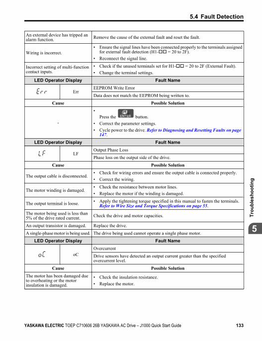
An external device has tripped analarm function. Remove the cause of the external fault and reset the fault.
Wiring is incorrect.• Ensure the signal lines have been connected properly to the terminals assigned
for external fault detection (H1-oo = 20 to 2F).• Reconnect the signal line.
Incorrect setting of multi-functioncontact inputs.
• Check if the unused terminals set for H1-oo = 20 to 2F (External Fault).• Change the terminal settings.
LED Operator Display Fault Name
ErrEEPROM Write Error
Data does not match the EEPROM being written to.
Cause Possible Solution
-
•Press the button.
• Correct the parameter settings.• Cycle power to the drive. Refer to Diagnosing and Resetting Faults on page
147.
LED Operator Display Fault Name
LFOutput Phase Loss
Phase loss on the output side of the drive.
Cause Possible Solution
The output cable is disconnected.• Check for wiring errors and ensure the output cable is connected properly.• Correct the wiring.
The motor winding is damaged.• Check the resistance between motor lines.• Replace the motor if the winding is damaged.
The output terminal is loose. • Apply the tightening torque specified in this manual to fasten the terminals.Refer to Wire Size and Torque Specifications on page 55.
The motor being used is less than5% of the drive rated current. Check the drive and motor capacities.
An output transistor is damaged. Replace the drive.
A single-phase motor is being used. The drive being used cannot operate a single phase motor.
LED Operator Display Fault Name
oCOvercurrent
Drive sensors have detected an output current greater than the specifiedovercurrent level.
Cause Possible SolutionThe motor has been damaged dueto overheating or the motorinsulation is damaged.
• Check the insulation resistance.• Replace the motor.
5.4 Fault Detection
YASKAWA ELECTRIC TOEP C710606 26B YASKAWA AC Drive – J1000 Quick Start Guide 133
5
Trou
bles
hoot
ing
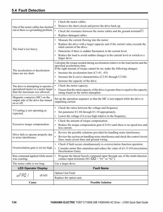
One of the motor cables has shortedout or there is a grounding problem.
• Check the motor cables.• Remove the short circuit and power the drive back up.
• Check the resistance between the motor cables and the ground terminal .• Replace damaged cables.
The load is too heavy.
• Measure the current flowing into the motor.• Replace the drive with a larger capacity unit if the current value exceeds the
rated current of the drive.• Determine if there is sudden fluctuation in the current level.• Reduce the load to avoid sudden changes in the current level or switch to a
larger drive.
The acceleration or decelerationtimes are too short.
Calculate the torque needed during acceleration relative to the load inertia and thespecified acceleration time.If the right amount of torque cannot be set, make the following changes:• Increase the acceleration time (C1-01, -03)• Increase the S-curve characteristics (C2-01 through C2-04)• Increase the capacity of the drive.
The drive is attempting to operate aspecialized motor or a motor largerthan the maximum size allowed.
• Check the motor capacity.• Ensure that the rated capacity of the drive is greater than or equal to the capacity
rating found on the motor nameplate.
Magnetic contactor (MC) on theoutput side of the drive has turnedon or off.
Set up the operation sequence so that the MC is not tripped while the drive isoutputting current.
V/f setting is not operating asexpected.
• Check the ratios between the voltage and frequency.• Set parameter E1-04 through E1-10 appropriately.• Lower the voltage if it is too high relative to the frequency.
Excessive torque compensation.• Check the amount of torque compensation.• Reduce the torque compensation gain (C4-01) until there is no speed loss and
less current.
Drive fails to operate properly dueto noise interference.
• Review the possible solutions provided for handling noise interference.• Review the section on handling noise interference and check the control circuit
lines, main circuit lines and ground wiring.
Overexcitation gain is set too high.• Check if fault occurs simultaneously to overexcitation function operation.• Consider motor flux saturation and reduce the value of n3-13 (Overexcitation
Deceleration Gain).
Run command applied while motorwas coasting.
• Program the Speed Search command input through one of the multi-functioncontact input terminals (H1-oo = “61” or “62”).
The motor cable is too long Use a larger drive.
LED Operator Display Fault Name
oFA01Option Unit Fault
Replace the option unit.
Cause Possible Solution
5.4 Fault Detection
134 YASKAWA ELECTRIC TOEP C710606 26B YASKAWA AC Drive – J1000 Quick Start Guide
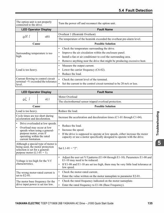
The option unit is not properlyconnected to the drive. Turn the power off and reconnect the option unit.
LED Operator Display Fault Name
oH1Overheat 1 (Heatsink Overheat)
The temperature of the heatsink exceeded the overheat pre-alarm level.
Cause Possible Solution
Surrounding temperature is toohigh.
• Check the temperature surrounding the drive.• Improve the air circulation within the enclosure panel.• Install a fan or air conditioner to cool the surrounding area.• Remove anything near the drive that might be producing excessive heat.
Load is too heavy.• Measure the output current.• Lower the carrier frequency (C6-02).• Reduce the load.
Current flowing to control circuitterminal +V exceeded the tolerancelevel.
• Check the current level of the terminal.• Set the current to the control circuit terminal to be 20 mA or less.
LED Operator Display Fault Name
oL1Motor Overload
The electrothermal sensor tripped overload protection.
Cause Possible SolutionLoad is too heavy. Reduce the load.
Cycle times are too short duringacceleration and deceleration. Increase the acceleration and deceleration times (C1-01 through C1-04).
• Drive overloaded at low speeds.• Overload may occur at low
speeds when using a general-purpose motor, even ifoperating within the ratedcurrent limitation.
• Reduce the load.• Increase the speed.• If the drive is supposed to operate at low speeds, either increase the motor
capacity or use a motor specifically designed to operate with the drive.
Although a special type of motor isbeing used, the motor protectionselection is set for a general-purpose motor (L1-01 = 1).
Set L1-01 = “2”.
Voltage is too high for the V/fcharacteristics.
• Adjust the user set V/f patterns (E1-04 through E1-10). Parameters E1-08 andE1-10 may need to be reduced.
• If E1-08 and E1-10 are set too high, there may be very little load tolerance atlow speed.
The wrong motor-rated current isset to E2-01.
• Check the motor-rated current.• Enter the value written on the motor nameplate to parameter E2-01.
The motor base frequency for thedrive input power is set too low.
• Check the rated frequency indicated on the motor nameplate.• Enter the rated frequency to E1-06 (Base Frequency).
5.4 Fault Detection
YASKAWA ELECTRIC TOEP C710606 26B YASKAWA AC Drive – J1000 Quick Start Guide 135
5
Trou
bles
hoot
ing
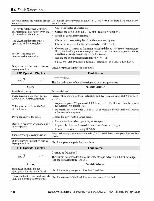
Multiple motors are running off thesame drive.
Disable the Motor Protection function (L1-01 = “0”) and install a thermal relayto each motor.
The electrical thermal protectioncharacteristics and motor overloadcharacteristics do not match.
• Check the motor characteristics.• Correct the value set to L1-01 (Motor Protection Function).• Install an external thermal relay.
The electrical thermal relay isoperating at the wrong level.
• Check the current rating listed on the motor nameplate.• Check the value set for the motor-rated current (E2-01).
Motor overheated byoverexcitation operation.
• Overexcitation increases the motor losses and thereby the motor temperature.If applied too long, motor damage can occur. Prevent excessive overexcitationoperation or apply proper cooling to the motor.
• Reduce the excitation deceleration gain (n3-13).• Set L3-04 (Stall Prevention during Deceleration) to a value other than 4.
Output current fluctuation due toinput phase loss Check the power supply for phase loss.
LED Operator Display Fault Name
oL2Drive Overload
The thermal sensor of the drive triggered overload protection.
Cause Possible SolutionLoad is too heavy. Reduce the load.
Cycle times are too short duringacceleration and deceleration.
Increase the settings for the acceleration and deceleration times (C1-01 throughC1-04).
Voltage is too high for the V/fcharacteristics.
• Adjust the preset V/f pattern (E1-04 through E1-10). This will mainly involvereducing E1-08 and E1-10.
• Be careful not to lower E1-08 and E1-10 excessively because this reduces loadtolerance at low speeds.
Drive capacity is too small. Replace the drive with a larger model.
Overload occurred when operatingat low speeds.
• Reduce the load when operating at low speeds.• Replace the drive with a model that is one frame size larger.• Lower the carrier frequency (C6-02).
Excessive torque compensation. Reduce the torque compensation gain (C4-01) until there is no speed loss but lesscurrent.
Output current fluctuation due toinput phase loss Check the power supply for phase loss.
LED Operator Display Fault Name
oL3Overtorque Detection 1
The current has exceeded the value set for torque detection (L6-02) for longerthan the allowable time (L6-03).
Cause Possible SolutionParameter settings are notappropriate for the type of load. Check the settings of parameters L6-02 and L6-03.
There is a fault on the machine side(e.g., the machine is locked up). Check the status of the load. Remove the cause of the fault.
5.4 Fault Detection
136 YASKAWA ELECTRIC TOEP C710606 26B YASKAWA AC Drive – J1000 Quick Start Guide
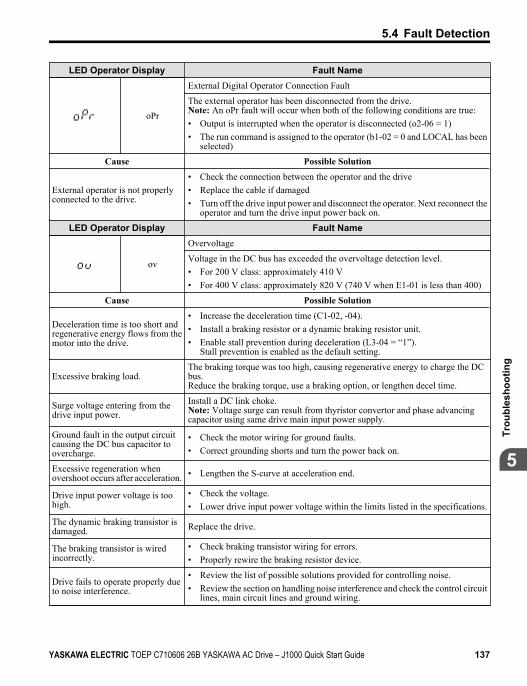
LED Operator Display Fault Name
oPr
External Digital Operator Connection Fault
The external operator has been disconnected from the drive.Note: An oPr fault will occur when both of the following conditions are true:• Output is interrupted when the operator is disconnected (o2-06 = 1)• The run command is assigned to the operator (b1-02 = 0 and LOCAL has been
selected)
Cause Possible Solution
External operator is not properlyconnected to the drive.
• Check the connection between the operator and the drive• Replace the cable if damaged• Turn off the drive input power and disconnect the operator. Next reconnect the
operator and turn the drive input power back on.
LED Operator Display Fault Name
ov
Overvoltage
Voltage in the DC bus has exceeded the overvoltage detection level.• For 200 V class: approximately 410 V• For 400 V class: approximately 820 V (740 V when E1-01 is less than 400)
Cause Possible Solution
Deceleration time is too short andregenerative energy flows from themotor into the drive.
• Increase the deceleration time (C1-02, -04).• Install a braking resistor or a dynamic braking resistor unit.• Enable stall prevention during deceleration (L3-04 = “1”).
Stall prevention is enabled as the default setting.
Excessive braking load.The braking torque was too high, causing regenerative energy to charge the DCbus.Reduce the braking torque, use a braking option, or lengthen decel time.
Surge voltage entering from thedrive input power.
Install a DC link choke.Note: Voltage surge can result from thyristor convertor and phase advancingcapacitor using same drive main input power supply.
Ground fault in the output circuitcausing the DC bus capacitor toovercharge.
• Check the motor wiring for ground faults.• Correct grounding shorts and turn the power back on.
Excessive regeneration whenovershoot occurs after acceleration. • Lengthen the S-curve at acceleration end.
Drive input power voltage is toohigh.
• Check the voltage.• Lower drive input power voltage within the limits listed in the specifications.
The dynamic braking transistor isdamaged. Replace the drive.
The braking transistor is wiredincorrectly.
• Check braking transistor wiring for errors.• Properly rewire the braking resistor device.
Drive fails to operate properly dueto noise interference.
• Review the list of possible solutions provided for controlling noise.• Review the section on handling noise interference and check the control circuit
lines, main circuit lines and ground wiring.
5.4 Fault Detection
YASKAWA ELECTRIC TOEP C710606 26B YASKAWA AC Drive – J1000 Quick Start Guide 137
5
Trou
bles
hoot
ing
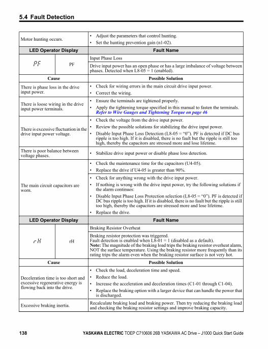
Motor hunting occurs.• Adjust the parameters that control hunting.• Set the hunting prevention gain (n1-02).
LED Operator Display Fault Name
PFInput Phase Loss
Drive input power has an open phase or has a large imbalance of voltage betweenphases. Detected when L8-05 = 1 (enabled).
Cause Possible Solution
There is phase loss in the driveinput power.
• Check for wiring errors in the main circuit drive input power.• Correct the wiring.
There is loose wiring in the driveinput power terminals.
• Ensure the terminals are tightened properly.• Apply the tightening torque specified in this manual to fasten the terminals.
Refer to Wire Gauges and Tightening Torque on page 46
There is excessive fluctuation in thedrive input power voltage.
• Check the voltage from the drive input power.• Review the possible solutions for stabilizing the drive input power.• Disable Input Phase Loss Detection (L8-05 = “0”). PF is detected if DC bus
ripple is too high. If it is disabled, there is no fault but the ripple is still toohigh, thereby the capacitors are stressed more and lose lifetime.
There is poor balance betweenvoltage phases. • Stabilize drive input power or disable phase loss detection.
The main circuit capacitors areworn.
• Check the maintenance time for the capacitors (U4-05).• Replace the drive if U4-05 is greater than 90%.
• Check for anything wrong with the drive input power.• If nothing is wrong with the drive input power, try the following solutions if
the alarm continues:• Disable Input Phase Loss Protection selection (L8-05 = “0”). PF is detected if
DC bus ripple is too high. If it is disabled, there is no fault but the ripple is stilltoo high, thereby the capacitors are stressed more and lose lifetime.
• Replace the drive.
LED Operator Display Fault Name
rH
Braking Resistor Overheat
Braking resistor protection was triggered.Fault detection is enabled when L8-01 = 1 (disabled as a default).Note: The magnitude of the braking load trips the braking resistor overheat alarm,NOT the surface temperature. Using the braking resistor more frequently than itsrating trips the alarm even when the braking resistor surface is not very hot.
Cause Possible Solution
Deceleration time is too short andexcessive regenerative energy isflowing back into the drive.
• Check the load, deceleration time and speed.• Reduce the load.• Increase the acceleration and deceleration times (C1-01 through C1-04).• Replace the braking option with a larger device that can handle the power that
is discharged.
Excessive braking inertia. Recalculate braking load and braking power. Then try reducing the braking loadand checking the braking resistor settings and improve braking capacity.
5.4 Fault Detection
138 YASKAWA ELECTRIC TOEP C710606 26B YASKAWA AC Drive – J1000 Quick Start Guide
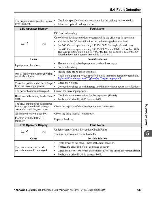
The proper braking resistor has notbeen installed.
• Check the specifications and conditions for the braking resistor device.• Select the optimal braking resistor.
LED Operator Display Fault Name
Uv1
DC Bus Undervoltage
One of the following conditions occurred while the drive was in operation:• Voltage in the DC bus fell below the undervoltage detection level.• For 200 V class: approximately 190 V (160 V for single phase drives)• For 400 V class: approximately 380 V (350 V when E1-01 is less than 400)
The fault is output only if L2-01 = 0 or the DC bus voltage is below the Uvdetection level for a certain time while L2-01 = 1.
Cause Possible Solution
Input power phase loss.• The main circuit drive input power is wired incorrectly.• Correct the wiring.
One of the drive input power wiringterminals is loose.
• Ensure there are no loose terminals.• Apply the tightening torque specified in this manual to fasten the terminals.
Refer to Wire Gauges and Tightening Torque on page 46
There is a problem with the voltagefrom the drive input power.
• Check the voltage.• Correct the voltage to within range listed in drive input power specifications.
The power has been interrupted. Correct the drive input power.
Drive internal circuitry has becomeworn.
• Check the maintenance time for the capacitors (U4-05).• Replace the drive if U4-05 exceeds 90%.
The drive input power transformeris not large enough and voltagedrops after switching on power.
Check the capacity of the drive input power transformer.
Air inside the drive is too hot. Check the drive internal temperature.
Problem with the CHARGEindicator. Replace the drive.
LED Operator Display Fault Name
Uv3Undervoltage 3 (Inrush Prevention Circuit Fault)
The inrush prevention circuit has failed.
Cause Possible Solution
The contactor on the inrushprevention circuit is damaged.
• Cycle power to the drive. Check if the fault reoccurs.• Replace the drive if the fault continues to occur.• Check monitor U4-06 for the performance life of the inrush prevention circuit.• Replace the drive if U4-06 exceeds 90%.
5.4 Fault Detection
YASKAWA ELECTRIC TOEP C710606 26B YASKAWA AC Drive – J1000 Quick Start Guide 139
5
Trou
bles
hoot
ing
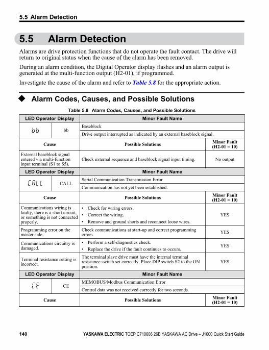
5.5 Alarm DetectionAlarms are drive protection functions that do not operate the fault contact. The drive willreturn to original status when the cause of the alarm has been removed.During an alarm condition, the Digital Operator display flashes and an alarm output isgenerated at the multi-function output (H2-01), if programmed.Investigate the cause of the alarm and refer to Table 5.8 for the appropriate action.
u Alarm Codes, Causes, and Possible SolutionsTable 5.8 Alarm Codes, Causes, and Possible Solutions
LED Operator Display Minor Fault Name
bbBaseblock
Drive output interrupted as indicated by an external baseblock signal.
Cause Possible Solutions Minor Fault(H2-01 = 10)
External baseblock signalentered via multi-functioninput terminal (S1 to S5).
Check external sequence and baseblock signal input timing. No output
LED Operator Display Minor Fault Name
CALLSerial Communication Transmission Error
Communication has not yet been established.
Cause Possible Solutions Minor Fault(H2-01 = 10)
Communications wiring isfaulty, there is a short circuit,or something is not connectedproperly.
• Check for wiring errors.• Correct the wiring.• Remove and ground shorts and reconnect loose wires.
YES
Programming error on themaster side.
Check communications at start-up and correct programmingerrors. YES
Communications circuitry isdamaged.
• Perform a self-diagnostics check.• Replace the drive if the fault continues to occurs.
YES
Terminal resistance setting isincorrect.
The terminal slave drive must have the internal terminalresistance switch set correctly. Place DIP switch S2 to the ONposition.
YES
LED Operator Display Minor Fault Name
CEMEMOBUS/Modbus Communication Error
Control data was not received correctly for two seconds.
Cause Possible Solutions Minor Fault(H2-01 = 10)
5.5 Alarm Detection
140 YASKAWA ELECTRIC TOEP C710606 26B YASKAWA AC Drive – J1000 Quick Start Guide
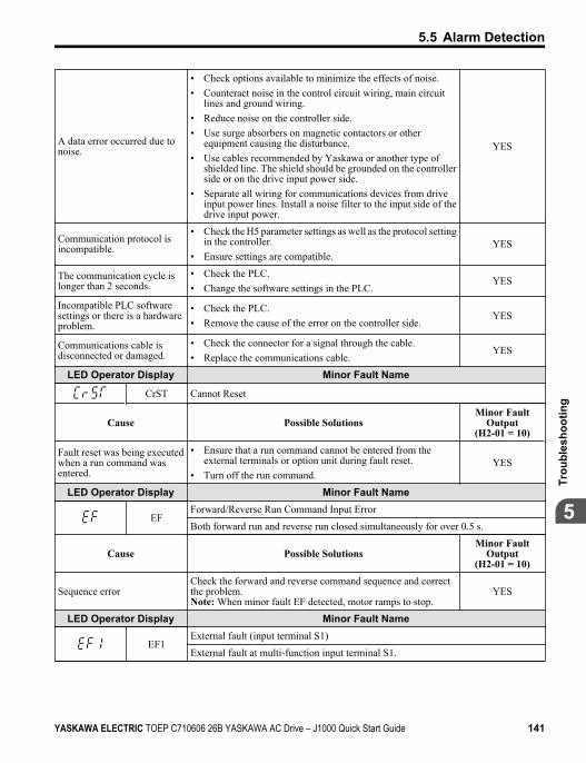
A data error occurred due tonoise.
• Check options available to minimize the effects of noise.• Counteract noise in the control circuit wiring, main circuit
lines and ground wiring.• Reduce noise on the controller side.• Use surge absorbers on magnetic contactors or other
equipment causing the disturbance.• Use cables recommended by Yaskawa or another type of
shielded line. The shield should be grounded on the controllerside or on the drive input power side.
• Separate all wiring for communications devices from driveinput power lines. Install a noise filter to the input side of thedrive input power.
YES
Communication protocol isincompatible.
• Check the H5 parameter settings as well as the protocol settingin the controller.
• Ensure settings are compatible.YES
The communication cycle islonger than 2 seconds.
• Check the PLC.• Change the software settings in the PLC.
YES
Incompatible PLC softwaresettings or there is a hardwareproblem.
• Check the PLC.• Remove the cause of the error on the controller side.
YES
Communications cable isdisconnected or damaged.
• Check the connector for a signal through the cable.• Replace the communications cable.
YES
LED Operator Display Minor Fault Name
CrST Cannot Reset
Cause Possible SolutionsMinor Fault
Output(H2-01 = 10)
Fault reset was being executedwhen a run command wasentered.
• Ensure that a run command cannot be entered from theexternal terminals or option unit during fault reset.
• Turn off the run command.YES
LED Operator Display Minor Fault Name
EFForward/Reverse Run Command Input Error
Both forward run and reverse run closed simultaneously for over 0.5 s.
Cause Possible SolutionsMinor Fault
Output(H2-01 = 10)
Sequence errorCheck the forward and reverse command sequence and correctthe problem.Note: When minor fault EF detected, motor ramps to stop.
YES
LED Operator Display Minor Fault Name
EF1External fault (input terminal S1)
External fault at multi-function input terminal S1.
5.5 Alarm Detection
YASKAWA ELECTRIC TOEP C710606 26B YASKAWA AC Drive – J1000 Quick Start Guide 141
5
Trou
bles
hoot
ing
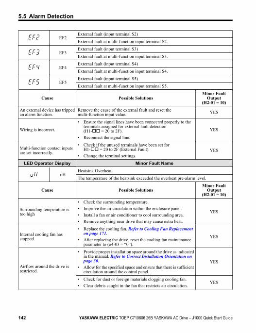
EF2External fault (input terminal S2)
External fault at multi-function input terminal S2.
EF3External fault (input terminal S3)
External fault at multi-function input terminal S3.
EF4External fault (input terminal S4)
External fault at multi-function input terminal S4.
EF5External fault (input terminal S5)
External fault at multi-function input terminal S5.
Cause Possible SolutionsMinor Fault
Output(H2-01 = 10)
An external device has trippedan alarm function.
Remove the cause of the external fault and reset themulti-function input value. YES
Wiring is incorrect.
• Ensure the signal lines have been connected properly to theterminals assigned for external fault detection(H1-oo = 20 to 2F).
• Reconnect the signal line.
YES
Multi-function contact inputsare set incorrectly.
• Check if the unused terminals have been set forH1-oo = 20 to 2F (External Fault).
• Change the terminal settings.YES
LED Operator Display Minor Fault Name
oHHeatsink Overheat
The temperature of the heatsink exceeded the overheat pre-alarm level.
Cause Possible SolutionsMinor Fault
Output(H2-01 = 10)
Surrounding temperature istoo high
• Check the surrounding temperature.• Improve the air circulation within the enclosure panel.• Install a fan or air conditioner to cool surrounding area.• Remove anything near drive that may cause extra heat.
YES
Internal cooling fan hasstopped.
• Replace the cooling fan. Refer to Cooling Fan Replacement on page 171.
• After replacing the drive, reset the cooling fan maintenanceparameter to (o4-03 = “0”).
YES
Airflow around the drive isrestricted.
• Provide proper installation space around the drive as indicatedin the manual. Refer to Correct Installation Orientation on page 30.
• Allow for the specified space and ensure that there is sufficientcirculation around the control panel.
YES
• Check for dust or foreign materials clogging cooling fan.• Clear debris caught in the fan that restricts air circulation.
YES
5.5 Alarm Detection
142 YASKAWA ELECTRIC TOEP C710606 26B YASKAWA AC Drive – J1000 Quick Start Guide
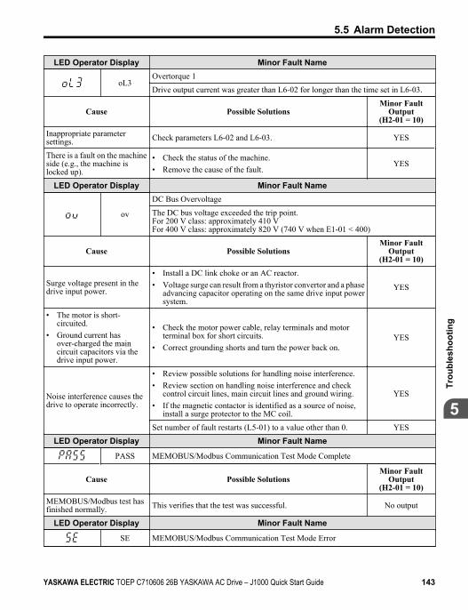
LED Operator Display Minor Fault Name
oL3Overtorque 1
Drive output current was greater than L6-02 for longer than the time set in L6-03.
Cause Possible SolutionsMinor Fault
Output(H2-01 = 10)
Inappropriate parametersettings. Check parameters L6-02 and L6-03. YES
There is a fault on the machineside (e.g., the machine islocked up).
• Check the status of the machine.• Remove the cause of the fault.
YES
LED Operator Display Minor Fault Name
ov
DC Bus Overvoltage
The DC bus voltage exceeded the trip point.For 200 V class: approximately 410 VFor 400 V class: approximately 820 V (740 V when E1-01 < 400)
Cause Possible SolutionsMinor Fault
Output(H2-01 = 10)
Surge voltage present in thedrive input power.
• Install a DC link choke or an AC reactor.• Voltage surge can result from a thyristor convertor and a phase
advancing capacitor operating on the same drive input powersystem.
YES
• The motor is short-circuited.
• Ground current hasover-charged the maincircuit capacitors via thedrive input power.
• Check the motor power cable, relay terminals and motorterminal box for short circuits.
• Correct grounding shorts and turn the power back on.YES
Noise interference causes thedrive to operate incorrectly.
• Review possible solutions for handling noise interference.• Review section on handling noise interference and check
control circuit lines, main circuit lines and ground wiring.• If the magnetic contactor is identified as a source of noise,
install a surge protector to the MC coil.
YES
Set number of fault restarts (L5-01) to a value other than 0. YES
LED Operator Display Minor Fault Name
PASS MEMOBUS/Modbus Communication Test Mode Complete
Cause Possible SolutionsMinor Fault
Output(H2-01 = 10)
MEMOBUS/Modbus test hasfinished normally. This verifies that the test was successful. No output
LED Operator Display Minor Fault Name
SE MEMOBUS/Modbus Communication Test Mode Error
5.5 Alarm Detection
YASKAWA ELECTRIC TOEP C710606 26B YASKAWA AC Drive – J1000 Quick Start Guide 143
5
Trou
bles
hoot
ing
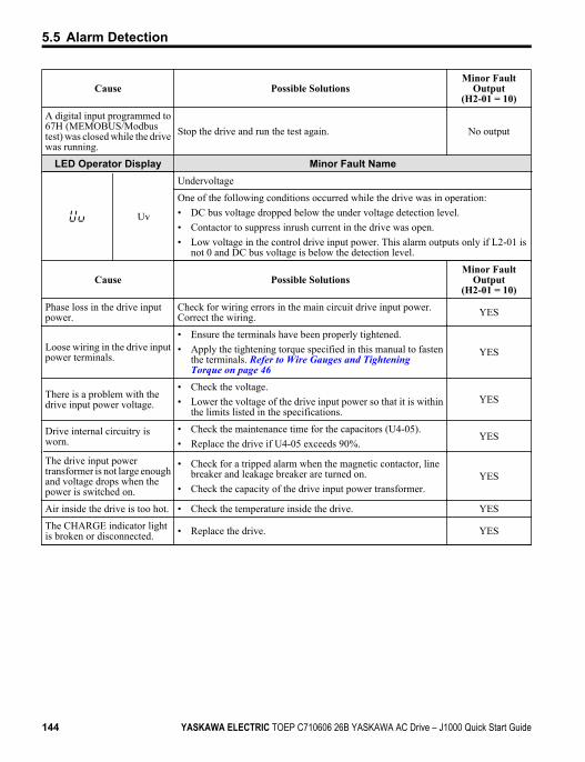
Cause Possible SolutionsMinor Fault
Output(H2-01 = 10)
A digital input programmed to67H (MEMOBUS/Modbustest) was closed while the drivewas running.
Stop the drive and run the test again. No output
LED Operator Display Minor Fault Name
Uv
Undervoltage
One of the following conditions occurred while the drive was in operation:• DC bus voltage dropped below the under voltage detection level.• Contactor to suppress inrush current in the drive was open.• Low voltage in the control drive input power. This alarm outputs only if L2-01 is
not 0 and DC bus voltage is below the detection level.
Cause Possible SolutionsMinor Fault
Output(H2-01 = 10)
Phase loss in the drive inputpower.
Check for wiring errors in the main circuit drive input power.Correct the wiring. YES
Loose wiring in the drive inputpower terminals.
• Ensure the terminals have been properly tightened.• Apply the tightening torque specified in this manual to fasten
the terminals. Refer to Wire Gauges and Tightening Torque on page 46
YES
There is a problem with thedrive input power voltage.
• Check the voltage.• Lower the voltage of the drive input power so that it is within
the limits listed in the specifications.YES
Drive internal circuitry isworn.
• Check the maintenance time for the capacitors (U4-05).• Replace the drive if U4-05 exceeds 90%.
YES
The drive input powertransformer is not large enoughand voltage drops when thepower is switched on.
• Check for a tripped alarm when the magnetic contactor, linebreaker and leakage breaker are turned on.
• Check the capacity of the drive input power transformer.YES
Air inside the drive is too hot. • Check the temperature inside the drive. YES
The CHARGE indicator lightis broken or disconnected. • Replace the drive. YES
5.5 Alarm Detection
144 YASKAWA ELECTRIC TOEP C710606 26B YASKAWA AC Drive – J1000 Quick Start Guide
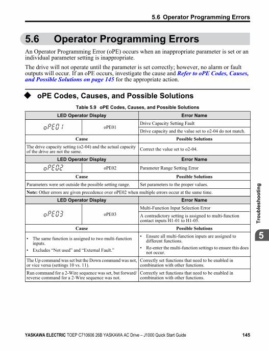
5.6 Operator Programming ErrorsAn Operator Programming Error (oPE) occurs when an inappropriate parameter is set or anindividual parameter setting is inappropriate.The drive will not operate until the parameter is set correctly; however, no alarm or faultoutputs will occur. If an oPE occurs, investigate the cause and Refer to oPE Codes, Causes, and Possible Solutions on page 145 for the appropriate action.
u oPE Codes, Causes, and Possible SolutionsTable 5.9 oPE Codes, Causes, and Possible Solutions
LED Operator Display Error Name
oPE01Drive Capacity Setting Fault
Drive capacity and the value set to o2-04 do not match.
Cause Possible SolutionsThe drive capacity setting (o2-04) and the actual capacityof the drive are not the same. Correct the value set to o2-04.
LED Operator Display Error Name
oPE02 Parameter Range Setting Error
Cause Possible SolutionsParameters were set outside the possible setting range. Set parameters to the proper values.
Note: Other errors are given precedence over oPE02 when multiple errors occur at the same time.
LED Operator Display Error Name
oPE03Multi-Function Input Selection Error
A contradictory setting is assigned to multi-functioncontact inputs H1-01 to H1-05.
Cause Possible Solutions
• The same function is assigned to two multi-functioninputs.
• Excludes “Not used” and “External Fault.”
• Ensure all multi-function inputs are assigned todifferent functions.
• Re-enter the multi-function settings to ensure this doesnot occur.
The Up command was set but the Down command was not,or vice versa (settings 10 vs. 11).
Correctly set functions that need to be enabled incombination with other functions.
Run command for a 2-Wire sequence was set, but forward/reverse command for a 2-Wire sequence was not.
Correctly set functions that need to be enabled incombination with other functions.
5.6 Operator Programming Errors
YASKAWA ELECTRIC TOEP C710606 26B YASKAWA AC Drive – J1000 Quick Start Guide 145
5
Trou
bles
hoot
ing
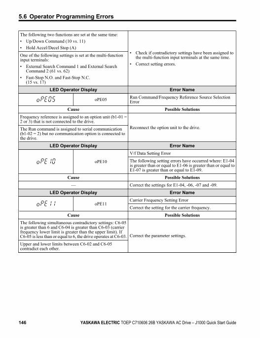
The following two functions are set at the same time:• Up/Down Command (10 vs. 11)• Hold Accel/Decel Stop (A)
• Check if contradictory settings have been assigned tothe multi-function input terminals at the same time.
• Correct setting errors.
One of the following settings is set at the multi-functioninput terminals:• External Search Command 1 and External Search
Command 2 (61 vs. 62)• Fast-Stop N.O. and Fast-Stop N.C.
(15 vs. 17)
LED Operator Display Error Name
oPE05 Run Command/Frequency Reference Source SelectionError
Cause Possible SolutionsFrequency reference is assigned to an option unit (b1-01 =2 or 3) that is not connected to the drive.
Reconnect the option unit to the drive.The Run command is assigned to serial communication(b1-02 = 2) but no communication option is connected tothe drive.
LED Operator Display Error Name
oPE10
V/f Data Setting Error
The following setting errors have occurred where: E1-04is greater than or equal to E1-06 is greater than or equal toE1-07 is greater than or equal to E1-09.
Cause Possible Solutions— Correct the settings for E1-04, -06, -07 and -09.
LED Operator Display Error Name
oPE11Carrier Frequency Setting Error
Correct the setting for the carrier frequency.
Cause Possible SolutionsThe following simultaneous contradictory settings: C6-05is greater than 6 and C6-04 is greater than C6-03 (carrierfrequency lower limit is greater than the upper limit). IfC6-05 is less than or equal to 6, the drive operates at C6-03. Correct the parameter settings.
Upper and lower limits between C6-02 and C6-05contradict each other.
5.6 Operator Programming Errors
146 YASKAWA ELECTRIC TOEP C710606 26B YASKAWA AC Drive – J1000 Quick Start Guide
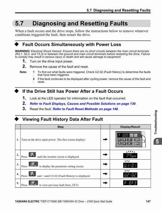
5.7 Diagnosing and Resetting FaultsWhen a fault occurs and the drive stops, follow the instructions below to remove whateverconditions triggered the fault, then restart the drive.
u Fault Occurs Simultaneously with Power LossWARNING! Electrical Shock Hazard. Ensure there are no short circuits between the main circuit terminals(R/L1, S/L2, and T/L3) or between the ground and main circuit terminals before restarting the drive. Failureto comply may result in serious injury or death and will cause damage to equipment.
1. Turn on the drive input power.2. Remove the cause of the fault and reset.
Note: 1.
To find out what faults were triggered, Check U2-02 (Fault History) to determine the faultsthat have been triggered.
2.
If the fault continues to be displayed after cycling power, remove the cause of the fault andreset.
u If the Drive Still has Power After a Fault Occurs1. Look at the LED operator for information on the fault that occurred.2. Refer to Fault Displays, Causes and Possible Solutions on page 130.3. Reset the fault. Refer to Fault Reset Methods on page 148.
u Viewing Fault History Data After Fault Step Display/Result
1. Turn on the drive input power. The first screen displays.STOP
2.Press until the monitor screen is displayed.
3.Press to display the parameter setting screen.
4.Press and > until U2-02 (Fault History) is displayed.
5.Press to view previous fault (here, EF3).
5.7 Diagnosing and Resetting Faults
YASKAWA ELECTRIC TOEP C710606 26B YASKAWA AC Drive – J1000 Quick Start Guide 147
5
Trou
bles
hoot
ing
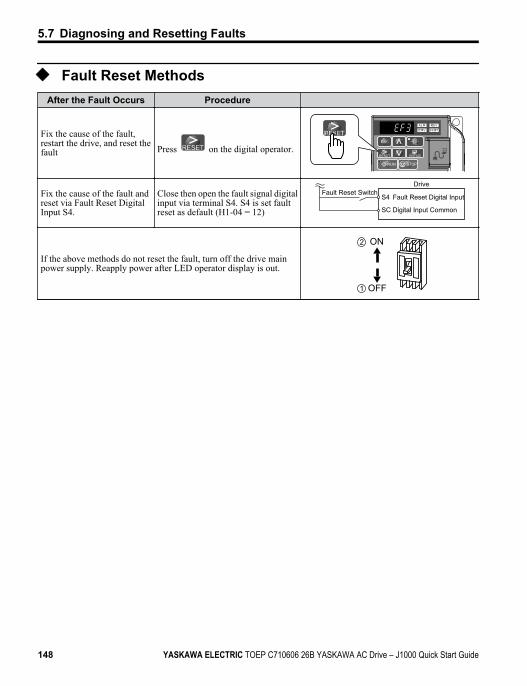
u Fault Reset MethodsAfter the Fault Occurs Procedure
Fix the cause of the fault,restart the drive, and reset thefault Press on the digital operator.
STOP
Fix the cause of the fault andreset via Fault Reset DigitalInput S4.
Close then open the fault signal digitalinput via terminal S4. S4 is set faultreset as default (H1-04 = 12)
Fault Reset SwitchDrive
S4 Fault Reset Digital Input
SC Digital Input Common
If the above methods do not reset the fault, turn off the drive mainpower supply. Reapply power after LED operator display is out.
ON
OFF
2
1
5.7 Diagnosing and Resetting Faults
148 YASKAWA ELECTRIC TOEP C710606 26B YASKAWA AC Drive – J1000 Quick Start Guide
5.8 Troubleshooting without Fault DisplayThis section describes troubleshooting problems that do not trip an alarm or fault.
u Cannot Change Parameter SettingsCause Possible Solutions
The drive is running the motor (i.e., theRun command is present).
• Stop the drive and switch over to the Programming Mode.• Most parameters cannot be edited during run.
The Access Level is set to restrict accessto parameter settings. • Set the Access Level to allow parameters to be edited (A1-01 = 2).
The operator is not in the Parameter SetupMode (the LED screen will display“PAr”).
• See what mode the LED parameter is current set for.• Parameters cannot be edited when in the Setup Mode (“STUP”). Switch
modes so that “PAr” appears on the screen.
The wrong password was entered.
• If the password entered to A1-04 does not match the password saved toA1-05, then drive settings cannot be changed.
• Reset the password.If you cannot remember the password:•
Display parameter A1-04. Press the STOP
button while pressing
at the same time. Parameter A1-05 will appear.• Set a new password to parameter A1-05.
Undervoltage was detected.• Check the drive input power voltage by looking at the DC bus voltage
(U1-07).• Check all main circuit wiring.
5.8 Troubleshooting without Fault Display
YASKAWA ELECTRIC TOEP C710606 26B YASKAWA AC Drive – J1000 Quick Start Guide 149
5
Trou
bles
hoot
ing
u Motor Does Not Rotate Properly after Pressing RUN Buttonor after Entering External Run Command
n Motor Does Not RotateCause Possible Solutions
The drive is not in the Drive Mode.• Check if the DRV light on the LED operator is lit.• Enter the Drive Mode to begin operating the motor. Refer to The Drive
and Programming Modes on page 79.
The button was pushed.
Stop the drive and check if the correct frequency reference source isselected. If the operator keypad shall be the source, the LO/RE button LEDmust be on, if the source is REMOTE, it must be off.Take the following step to solve the problem:•
Push the button.
A Fast-Stop was executed and has not yetbeen reset. Reset the Fast-Stop command.
Settings are incorrect for the source thatprovides the run command.
Check parameter b1-02 (Run Command Selection).Set b1-02 so that it corresponds with the correct run command source.0: LED operator1: Control circuit terminal (default setting)2: MEMOBUS/Modbus communications
There is faulty wiring in the control circuitterminals.
• Check the wiring for the control terminal.• Correct wiring mistakes.• Check the input terminal status monitor (U1-10).
The drive has been set to accept thefrequency reference from the incorrectsource.
Check parameter b1-01 (Frequency Reference Selection 1).Set b1-01 to the correct source of the frequency reference.0: LED operator1: Control circuit terminal (default setting)2: MEMOBUS/Modbus communications3: Potentiometer (option)
The terminal set to accept the main speedreference is set to the incorrect voltageand/or current.
Check DIP switch S1. Next assign the correct input level to terminal A1(H3-01). Refer to DIP Switch S1 Analog Input Signal Selection on page 62.
Selection for the sink/source mode isincorrect.
Check DIP switch S3. Refer to Sinking/Sourcing Mode Switch on page 59.
Frequency reference is too low.• Check the frequency reference monitor (U1-01).• Increase the frequency by changing the maximum output frequency
(E1-09).
Multi-function analog input is set up toaccept gain for the frequency reference,but no voltage (current) has beenprovided.
• Check the multi-function analog input settings.• Check if H3-02 has been set to the proper values.• Check if the analog input value has been set properly.
5.8 Troubleshooting without Fault Display
150 YASKAWA ELECTRIC TOEP C710606 26B YASKAWA AC Drive – J1000 Quick Start Guide
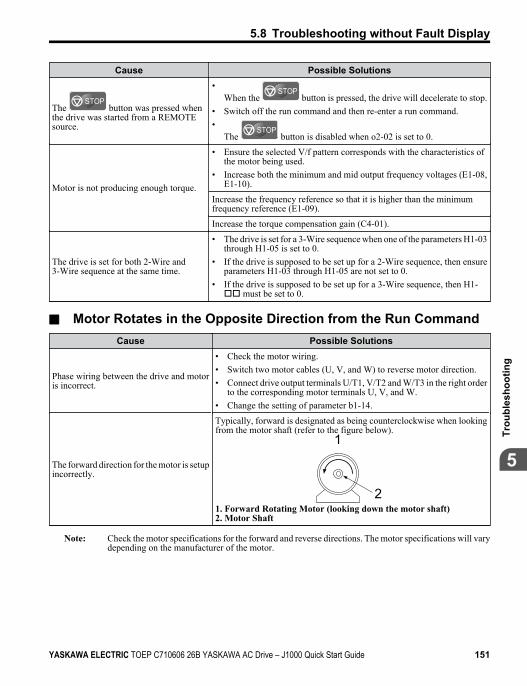
Cause Possible Solutions
The STOP
button was pressed whenthe drive was started from a REMOTEsource.
•When the
STOP button is pressed, the drive will decelerate to stop.
• Switch off the run command and then re-enter a run command.•
The STOP
button is disabled when o2-02 is set to 0.
Motor is not producing enough torque.
• Ensure the selected V/f pattern corresponds with the characteristics ofthe motor being used.
• Increase both the minimum and mid output frequency voltages (E1-08,E1-10).
Increase the frequency reference so that it is higher than the minimumfrequency reference (E1-09).
Increase the torque compensation gain (C4-01).
The drive is set for both 2-Wire and3-Wire sequence at the same time.
• The drive is set for a 3-Wire sequence when one of the parameters H1-03through H1-05 is set to 0.
• If the drive is supposed to be set up for a 2-Wire sequence, then ensureparameters H1-03 through H1-05 are not set to 0.
• If the drive is supposed to be set up for a 3-Wire sequence, then H1-oo must be set to 0.
n Motor Rotates in the Opposite Direction from the Run CommandCause Possible Solutions
Phase wiring between the drive and motoris incorrect.
• Check the motor wiring.• Switch two motor cables (U, V, and W) to reverse motor direction.• Connect drive output terminals U/T1, V/T2 and W/T3 in the right order
to the corresponding motor terminals U, V, and W.• Change the setting of parameter b1-14.
The forward direction for the motor is setupincorrectly.
Typically, forward is designated as being counterclockwise when lookingfrom the motor shaft (refer to the figure below).
1
21. Forward Rotating Motor (looking down the motor shaft)2. Motor Shaft
Note: Check the motor specifications for the forward and reverse directions. The motor specifications will varydepending on the manufacturer of the motor.
5.8 Troubleshooting without Fault Display
YASKAWA ELECTRIC TOEP C710606 26B YASKAWA AC Drive – J1000 Quick Start Guide 151
5
Trou
bles
hoot
ing
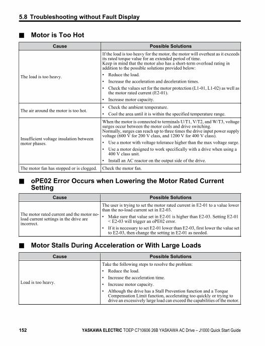
n Motor is Too HotCause Possible Solutions
The load is too heavy.
If the load is too heavy for the motor, the motor will overheat as it exceedsits rated torque value for an extended period of time.Keep in mind that the motor also has a short-term overload rating inaddition to the possible solutions provided below:• Reduce the load.• Increase the acceleration and deceleration times.• Check the values set for the motor protection (L1-01, L1-02) as well as
the motor rated current (E2-01).• Increase motor capacity.
The air around the motor is too hot.• Check the ambient temperature.• Cool the area until it is within the specified temperature range.
Insufficient voltage insulation betweenmotor phases.
When the motor is connected to terminals U/T1, V/T2, and W/T3, voltagesurges occur between the motor coils and drive switching.Normally, surges can reach up to three times the drive input power supplyvoltage (600 V for 200 V class, and 1200 V for 400 V class).• Use a motor with voltage tolerance higher than the max voltage surge.• Use a motor designed to work specifically with a drive when using a
400 V class unit.• Install an AC reactor on the output side of the drive.
The motor fan has stopped or is clogged. Check the motor fan.
n oPE02 Error Occurs when Lowering the Motor Rated CurrentSetting
Cause Possible Solutions
The motor rated current and the motor no-load current settings in the drive areincorrect.
The user is trying to set the motor rated current in E2-01 to a value lowerthan the no-load current set in E2-03.• Make sure that value set in E2-01 is higher than E2-03. Setting E2-01
< E2-03 will trigger an oPE02 error.• If it is necessary to set E2-01 lower than E2-03, first lower the value set
to E2-03, then change the setting in E2-01 as needed.
n Motor Stalls During Acceleration or With Large LoadsCause Possible Solutions
Load is too heavy.
Take the following steps to resolve the problem:• Reduce the load.• Increase the acceleration time.• Increase motor capacity.• Although the drive has a Stall Prevention function and a Torque
Compensation Limit function, accelerating too quickly or trying todrive an excessively large load can exceed the capabilities of the motor.
5.8 Troubleshooting without Fault Display
152 YASKAWA ELECTRIC TOEP C710606 26B YASKAWA AC Drive – J1000 Quick Start Guide
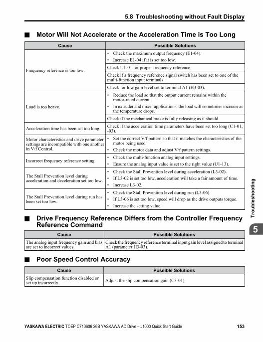
n Motor Will Not Accelerate or the Acceleration Time is Too LongCause Possible Solutions
Frequency reference is too low.
• Check the maximum output frequency (E1-04).• Increase E1-04 if it is set too low.
Check U1-01 for proper frequency reference.
Check if a frequency reference signal switch has been set to one of themulti-function input terminals.
Check for low gain level set to terminal A1 (H3-03).
Load is too heavy.
• Reduce the load so that the output current remains within themotor-rated current.
• In extruder and mixer applications, the load will sometimes increase asthe temperature drops.
Check if the mechanical brake is fully releasing as it should.
Acceleration time has been set too long. Check if the acceleration time parameters have been set too long (C1-01,-03).
Motor characteristics and drive parametersettings are incompatible with one anotherin V/f Control.
• Set the correct V/f pattern so that it matches the characteristics of themotor being used.
• Check the motor data and adjust V/f pattern settings.
Incorrect frequency reference setting.• Check the multi-function analog input settings.• Ensure the analog input value is set to the right value (U1-13).
The Stall Prevention level duringacceleration and deceleration set too low.
• Check the Stall Prevention level during acceleration (L3-02).• If L3-02 is set too low, acceleration will take a fair amount of time.• Increase L3-02.
The Stall Prevention level during run hasbeen set too low.
• Check the Stall Prevention level during run (L3-06).• If L3-06 is set too low, speed will drop as the drive outputs torque.• Increase the setting value.
n Drive Frequency Reference Differs from the Controller FrequencyReference Command
Cause Possible SolutionsThe analog input frequency gain and biasare set to incorrect values.
Check the frequency reference terminal input gain level assigned to terminalA1 (parameter H3-03).
n Poor Speed Control AccuracyCause Possible Solutions
Slip compensation function disabled orset up incorrectly. Adjust the slip compensation gain (C3-01).
5.8 Troubleshooting without Fault Display
YASKAWA ELECTRIC TOEP C710606 26B YASKAWA AC Drive – J1000 Quick Start Guide 153
5
Trou
bles
hoot
ing
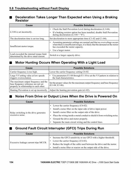
n Deceleration Takes Longer Than Expected when Using a BrakingResistor
Cause Possible Solutions
L3-04 is set incorrectly.• Check the Stall Prevention Level during deceleration (L3-04).• If a braking resistor option has been installed, disable Stall Prevention
during deceleration (L3-04 = “0”).
The deceleration time is set too long. Set deceleration to more appropriate time (C1-02 and C1-04).
Insufficient motor torque.
• Assuming parameter settings are normal and that no overvoltage occurswhen there is insufficient torque, it is likely that the demand on the motorhas exceeded the motor capacity.
• Use a larger motor.
Load exceeded the internal torque limitdetermined by the drive rated current. Switch to a larger capacity drive.
n Motor Hunting Occurs When Operating With a Light LoadCause Possible Solutions
Carrier frequency is too high. Lower the carrier frequency setting C6-02.
Large V/f setting value at low speedstriggers overexcitation.
• Use parameters E1-04 through E1-10 to set the V/f pattern in relation tothe load characteristics.
The maximum output frequency and thebase frequency reference are not setproperly in relationship to each other.
Set the proper values for the maximum output frequency and base frequency(E1-04, E1-06).
Hunting Prevention is set up incorrectly. Adjust the hunting prevention gain (n1-02).
n Noise From Drive or Output Lines When the Drive is Powered OnCause Possible Solutions
Relay switching in the drive generatesexcessive noise.
• Lower the carrier frequency (C6-02).• Install a noise filter on the input side of drive input power.• Install a noise filter on the output side of the drive.• Place the wiring inside a metal conduit to shield it from switching noise.• Ground the drive and motor properly.• Separate the main circuit wiring and the control lines.
n Ground Fault Circuit Interrupter (GFCI) Trips During RunCause Possible Solutions
Excessive leakage current trips MCCB.
• Increase the GFCI sensitivity or use GFCI with a higher threshold.• Lower the carrier frequency (C6-02).• Reduce the length of the cable used between the drive and the motor.• Install a noise filter or reactor on the output side of the drive.
5.8 Troubleshooting without Fault Display
154 YASKAWA ELECTRIC TOEP C710606 26B YASKAWA AC Drive – J1000 Quick Start Guide
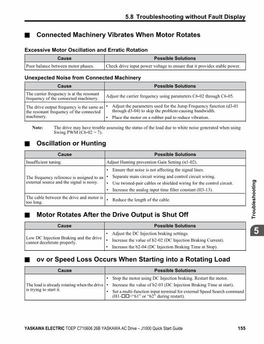
n Connected Machinery Vibrates When Motor Rotates
Excessive Motor Oscillation and Erratic RotationCause Possible Solutions
Poor balance between motor phases. Check drive input power voltage to ensure that it provides stable power.
Unexpected Noise from Connected MachineryCause Possible Solutions
The carrier frequency is at the resonantfrequency of the connected machinery. Adjust the carrier frequency using parameters C6-02 through C6-05.
The drive output frequency is the same asthe resonant frequency of the connectedmachinery.
• Adjust the parameters used for the Jump Frequency function (d3-01through d3-04) to skip the problem-causing bandwidth.
• Place the motor on a rubber pad to reduce vibration.
Note: The drive may have trouble assessing the status of the load due to white noise generated when usingSwing PWM (C6-02 = 7).
n Oscillation or HuntingCause Possible Solutions
Insufficient tuning. Adjust Hunting prevention Gain Setting (n1-02).
The frequency reference is assigned to anexternal source and the signal is noisy.
• Ensure that noise is not affecting the signal lines.• Separate main circuit wiring and control circuit wiring.• Use twisted-pair cables or shielded wiring for the control circuit.• Increase the analog input time filter constant (H3-13).
The cable between the drive and motor istoo long. • Reduce the length of the cable.
n Motor Rotates After the Drive Output is Shut OffCause Possible Solutions
Low DC Injection Braking and the drivecannot decelerate properly.
• Adjust the DC Injection braking settings.• Increase the value of b2-02 (DC Injection Braking Current).• Increase the b2-04 (DC Injection Braking Time at Stop).
n ov or Speed Loss Occurs When Starting into a Rotating LoadCause Possible Solutions
The load is already rotating when the driveis trying to start it.
• Stop the motor using DC Injection braking. Restart the motor.• Increase the value of b2-03 (DC Injection Braking Time at start).• Set a multi-function input terminal for external Speed Search command
(H1-oo=“61” or “62” during restart).
5.8 Troubleshooting without Fault Display
YASKAWA ELECTRIC TOEP C710606 26B YASKAWA AC Drive – J1000 Quick Start Guide 155
5
Trou
bles
hoot
ing
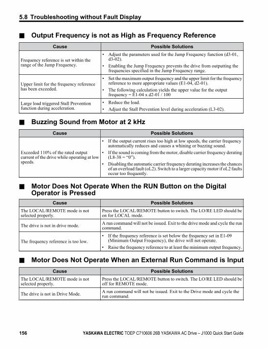
n Output Frequency is not as High as Frequency ReferenceCause Possible Solutions
Frequency reference is set within therange of the Jump Frequency.
• Adjust the parameters used for the Jump Frequency function (d3-01,d3-02).
• Enabling the Jump Frequency prevents the drive from outputting thefrequencies specified in the Jump Frequency range.
Upper limit for the frequency referencehas been exceeded.
• Set the maximum output frequency and the upper limit for the frequencyreference to more appropriate values (E1-04, d2-01).
• The following calculation yields the upper value for the outputfrequency = E1-04 x d2-01 / 100
Large load triggered Stall Preventionfunction during acceleration.
• Reduce the load.• Adjust the Stall Prevention level during acceleration (L3-02).
n Buzzing Sound from Motor at 2 kHzCause Possible Solutions
Exceeded 110% of the rated outputcurrent of the drive while operating at lowspeeds.
• If the output current rises too high at low speeds, the carrier frequencyautomatically reduces and causes a whining or buzzing sound.
• If the sound is coming from the motor, disable carrier frequency derating(L8-38 = “0”).
• Disabling the automatic carrier frequency derating increases the chancesof an overload fault (oL2). Switch to a larger capacity motor if oL2 faultsoccur too frequently.
n Motor Does Not Operate When the RUN Button on the DigitalOperator is Pressed
Cause Possible SolutionsThe LOCAL/REMOTE mode is notselected properly.
Press the LOCAL/REMOTE button to switch. The LO/RE LED should beon for LOCAL mode.
The drive is not in drive mode. A run command will not be issued. Exit to the drive mode and cycle the runcommand.
The frequency reference is too low.• If the frequency reference is set below the frequency set in E1-09
(Minimum Output Frequency), the drive will not operate.• Raise the frequency reference to at least the minimum output frequency.
n Motor Does Not Operate When an External Run Command is InputCause Possible Solutions
The LOCAL/REMOTE mode is notselected properly.
Press the LOCAL/REMOTE button to switch. The LO/RE LED should beoff for REMOTE mode.
The drive is not in Drive Mode. A run command will not be issued. Exit to the Drive mode and cycle therun command.
5.8 Troubleshooting without Fault Display
156 YASKAWA ELECTRIC TOEP C710606 26B YASKAWA AC Drive – J1000 Quick Start Guide
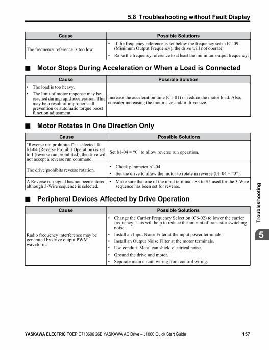
Cause Possible Solutions
The frequency reference is too low.• If the frequency reference is set below the frequency set in E1-09
(Minimum Output Frequency), the drive will not operate.• Raise the frequency reference to at least the minimum output frequency.
n Motor Stops During Acceleration or When a Load is ConnectedCause Possible Solution
• The load is too heavy.• The limit of motor response may be
reached during rapid acceleration. Thismay be a result of improper stallprevention or automatic torque boostfunction adjustment.
Increase the acceleration time (C1-01) or reduce the motor load. Also,consider increasing the motor size and/or drive size.
n Motor Rotates in One Direction OnlyCause Possible Solutions
"Reverse run prohibited" is selected. If b1-04 (Reverse Prohibit Operation) is setto 1 (reverse run prohibited), the drive willnot accept a reverse run command.
Set b1-04 = “0” to allow reverse run operation.
The drive prohibits reverse rotation.• Check parameter b1-04.• Set the drive to allow the motor to rotate in reverse (b1-04 = “0”).
A Reverse run signal has not been entered,although 3-Wire sequence is selected.
• Make sure that one of the input terminals S3 to S5 used for the 3-Wiresequence has been set for reverse.
n Peripheral Devices Affected by Drive OperationCause Possible Solutions
Radio frequency interference may begenerated by drive output PWMwaveform.
• Change the Carrier Frequency Selection (C6-02) to lower the carrierfrequency. This will help to reduce the amount of transistor switchingnoise.
• Install an Input Noise Filter at the input power terminals.• Install an Output Noise Filter at the motor terminals.• Use conduit. Metal can shield electrical noise.• Ground the drive and motor.• Separate main circuit wiring from control wiring.
5.8 Troubleshooting without Fault Display
YASKAWA ELECTRIC TOEP C710606 26B YASKAWA AC Drive – J1000 Quick Start Guide 157
5
Trou
bles
hoot
ing
n Ground Fault Interrupter Activates When Drive is RunningCause Possible Solutions
The output of the drive is a series of highfrequency pulses (PWM), so there is acertain amount of leakage current. Thismay cause the ground fault interrupter tooperate and cut off the drive input power.
• Change to a ground fault interrupter with a higher leakage currentdetection level (such as, a sensitivity current of 200 mA or greater perUnit, with an operating time of 0.1 s or more), or one that incorporateshigh-frequency corrective actions.
• Change the Carrier Frequency Selection (C6-02) to lower the carrierfrequency.Note: Leakage current increases in proportion to cable length.
5.8 Troubleshooting without Fault Display
158 YASKAWA ELECTRIC TOEP C710606 26B YASKAWA AC Drive – J1000 Quick Start Guide
PeriodicInspection &Maintenance
This chapter describes the periodic inspection and maintenanceof the drive to ensure that it receives the proper care to maintainoverall performance.
6.1 SECTION SAFETY...........................................1606.2 INSPECTION...................................................1636.3 PERIODIC MAINTENANCE..............................1676.4 DRIVE COOLING FANS...................................170
6
YASKAWA ELECTRIC TOEP C710606 26B YASKAWA AC Drive – J1000 Quick Start Guide 159
6.1 Section Safety
DANGER
Electrical Shock HazardDo not connect or disconnect wiring while the power is on.Failure to comply will result in death or serious injury.
WARNING
Electrical Shock HazardDo not operate equipment with covers removed.Failure to comply could result in death or serious injury.The diagrams in this section may show drives without covers or safety shields to showdetails. Be sure to reinstall covers or shields before operating the drives and run the drivesaccording to the instructions described in this manual.Always ground the motor-side grounding terminal.Improper equipment grounding could result in death or serious injury by contacting themotor case.Do not remove covers or touch circuit boards while the power is on.Failure to comply could result in death or serious injury.Do not allow unqualified personnel to perform work on the drive.Failure to comply could result in death or serious injury.Installation, maintenance, inspection, and servicing must be performed only by authorizedpersonnel familiar with installation, adjustment, and maintenance of AC drives.Do not perform work on the drive while wearing loose clothing, jewelry or without eyeprotection.Failure to comply could result in death or serious injury.Remove all metal objects such as watches and rings, secure loose clothing, and wear eyeprotection before beginning work on the drive.
6.1 Section Safety
160 YASKAWA ELECTRIC TOEP C710606 26B YASKAWA AC Drive – J1000 Quick Start Guide
WARNINGDo not touch any terminals before the capacitors have fully discharged.Failure to comply could result in death or serious injury.Before wiring terminals, disconnect all power to the equipment. The internal capacitorremains charged even after the power supply is turned off. The charge indicator LED willextinguish when the DC bus voltage is below 50 Vdc. To prevent electric shock, wait atleast one minute after all indicators are off and measure the DC bus voltage level to confirmsafe level.
Fire HazardTighten all terminal screws to the specified tightening torque.Loose electrical connections could result in death or serious injury by fire due to overheatingof electrical connections.Do not use an improper voltage source.Failure to comply could result in death or serious injury by fire.Verify that the rated voltage of the drive matches the voltage of the incoming power supplybefore applying power.Do not use improper combustible materials.Failure to comply could result in death or serious injury by fire.Attach the drive to metal or other noncombustible material.
6.1 Section Safety
YASKAWA ELECTRIC TOEP C710606 26B YASKAWA AC Drive – J1000 Quick Start Guide 161
6Pe
riodi
c In
spec
tion
&M
aint
enan
ce
NOTICE
Observe proper electrostatic discharge procedures (ESD) when handling the drive andcircuit boards.Failure to comply may result in ESD damage to the drive circuitry.Never connect or disconnect the motor from the drive while the drive is outputtingvoltage.Improper equipment sequencing could result in damage to the drive.Do not use unshielded cable for control wiring.Failure to comply may cause electrical interference resulting in poor system performance.Use shielded, twisted-pair wires and ground the shield to the ground terminal of the drive.Do not allow unqualified personnel to use the product.Failure to comply could result in damage to the drive or braking circuit.Carefully review instruction manual TOBPC72060000 when connecting a braking optionto the drive.Do not modify the drive circuitry.Failure to comply could result in damage to the drive and will void warranty.Yaskawa is not responsible for any modification of the product made by the user. Thisproduct must not be modified.Check all the wiring to ensure that all connections are correct after installing the driveand connecting any other devices.Failure to comply could result in damage to the drive.
6.1 Section Safety
162 YASKAWA ELECTRIC TOEP C710606 26B YASKAWA AC Drive – J1000 Quick Start Guide
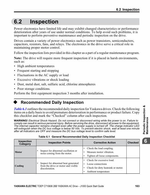
6.2 InspectionPower electronics have limited life and may exhibit changed characteristics or performancedeterioration after years of use under normal conditions. To help avoid such problems, it isimportant to perform preventive maintenance and periodic inspection on the drive.Drives contain a variety of power electronics such as power transistors, semiconductors,capacitors, resistors, fans, and relays. The electronics in the drive serve a critical role inmaintaining proper motor control.Follow the inspection lists provided in this chapter as a part of a regular maintenance program.Note: The drive will require more frequent inspection if it is placed in harsh environments,such as:• High ambient temperatures• Frequent starting and stopping• Fluctuations in the AC supply or load• Excessive vibrations or shock loading• Dust, metal dust, salt, sulfuric acid, chlorine atmospheres• Poor storage conditions.Perform the first equipment inspection 3 months after installation.
u Recommended Daily InspectionTable 6.1 outlines the recommended daily inspection for Yaskawa drives. Check the followingitems on a daily basis to avoid premature deterioration in performance or product failure. Copythis checklist and mark the “Checked” column after each inspection.WARNING! Electrical Shock Hazard. Do not connect or disconnect wiring while the power is on. Failure tocomply can result in serious personal injury. Before servicing the drive, disconnect all power to the equipment.The internal capacitor remains charged even after the power supply is turned off. The charge indicator LEDwill extinguish when the DC bus voltage is below 50 Vdc. To prevent electric shock, wait at least one minuteafter all indicators are OFF and measure the DC bus voltage level to confirm safe level.
Table 6.1 General Recommended Daily Inspection ChecklistInspectionCategory Inspection Points Corrective Action Checked
Motor • Inspect for abnormal oscillation ornoise coming from the motor.
• Check the load coupling.• Measure motor vibration.• Tighten all loose components.
Cooling• Inspect for abnormal heat generated
from the drive or motor and visiblediscoloration.
• Check for excessive load.• Loose connections• Check for dirty heatsink or motor.• Ambient temperature
6.2 Inspection
YASKAWA ELECTRIC TOEP C710606 26B YASKAWA AC Drive – J1000 Quick Start Guide 163
6Pe
riodi
c In
spec
tion
&M
aint
enan
ce
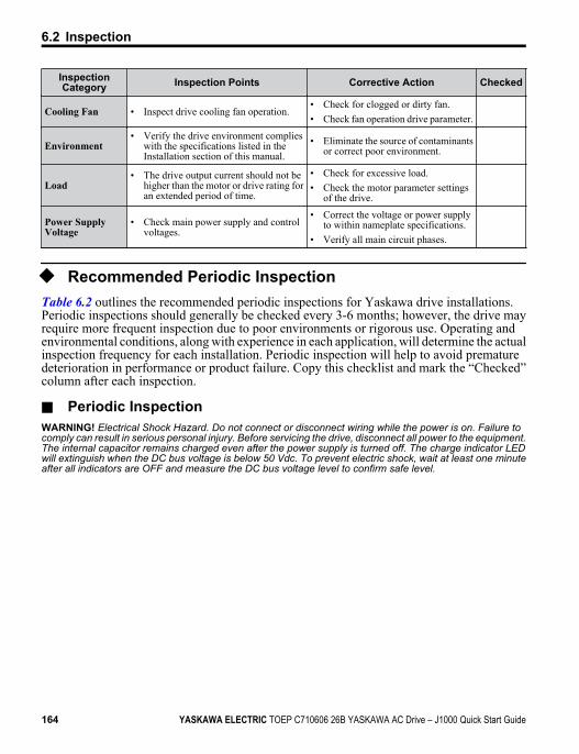
InspectionCategory Inspection Points Corrective Action Checked
Cooling Fan • Inspect drive cooling fan operation.• Check for clogged or dirty fan.• Check fan operation drive parameter.
Environment• Verify the drive environment complies
with the specifications listed in theInstallation section of this manual.
• Eliminate the source of contaminantsor correct poor environment.
Load• The drive output current should not be
higher than the motor or drive rating foran extended period of time.
• Check for excessive load.• Check the motor parameter settings
of the drive.
Power SupplyVoltage
• Check main power supply and controlvoltages.
• Correct the voltage or power supplyto within nameplate specifications.
• Verify all main circuit phases.
u Recommended Periodic InspectionTable 6.2 outlines the recommended periodic inspections for Yaskawa drive installations.Periodic inspections should generally be checked every 3-6 months; however, the drive mayrequire more frequent inspection due to poor environments or rigorous use. Operating andenvironmental conditions, along with experience in each application, will determine the actualinspection frequency for each installation. Periodic inspection will help to avoid prematuredeterioration in performance or product failure. Copy this checklist and mark the “Checked”column after each inspection.
n Periodic InspectionWARNING! Electrical Shock Hazard. Do not connect or disconnect wiring while the power is on. Failure tocomply can result in serious personal injury. Before servicing the drive, disconnect all power to the equipment.The internal capacitor remains charged even after the power supply is turned off. The charge indicator LEDwill extinguish when the DC bus voltage is below 50 Vdc. To prevent electric shock, wait at least one minuteafter all indicators are OFF and measure the DC bus voltage level to confirm safe level.
6.2 Inspection
164 YASKAWA ELECTRIC TOEP C710606 26B YASKAWA AC Drive – J1000 Quick Start Guide
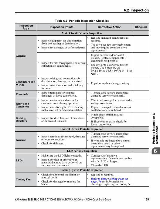
Table 6.2 Periodic Inspection ChecklistInspection
Area Inspection Points Corrective Action Checked
Main Circuit Periodic Inspection
General
• Inspect equipment for discolorationfrom overheating or deterioration.
• Inspect for damaged or deformed parts.
• Replace damaged components asrequired.
• The drive has few serviceable partsand may require complete drivereplacement.
• Inspect for dirt, foreign particles, or dustcollection on components.
• Inspect enclosure door seal ifpresent. Replace components ifcleaning is not possible.
• Use dry air to clear away foreignmatter. Use a pressure of:39.2 x 10⁴ to 58.8 x 10⁴ Pa (4 - 6 kg•cm2).
Conductors andWiring
• Inspect wiring and connections fordiscoloration, damage, or heat stress.
• Inspect wire insulation and shieldingfor wear.
• Repair or replace damaged wiring.
Terminals • Inspect terminals for stripped,damaged, or loose connections.
• Tighten loose screws and replacedamaged screws or terminals.
Relays andContactors
• Inspect contactors and relays forexcessive noise during operation.
• Inspect coils for signs of overheatingsuch as melted or cracked insulation.
• Check coil voltage for over or undervoltage conditions.
• Replace damaged removable relayscontactors or circuit board.
BrakingResistors
• Inspect for discoloration of heat stresson or around resistors.
• Minor discoloration may beacceptable.
• If discoloration exists check forloose connections.
Control Circuit Periodic Inspection
General• Inspect terminals for stripped, damaged
or loose connections.• Check for tightness.
• Tighten loose screws and replacedamaged screws or terminals.
• If terminals are integral to a circuitboard then board or drivereplacement may be required.
LED Periodic Inspection
LEDs
• Make sure the LED lights correctly.• Inspect for dust or other foreign
material that may have collected onsurrounding components.
• Contact your Yaskawarepresentative if there is any troublewith the LED or keypad.
• Clean the LED.
Cooling System Periodic Inspection
Cooling Fan
• Check for abnormal oscillation orunusual noise.
• Check for damaged or missing fanblades.
• Replace as required.• Refer to Drive Cooling Fans on
page 170 for information oncleaning or replacing the cooling fan.
6.2 Inspection
YASKAWA ELECTRIC TOEP C710606 26B YASKAWA AC Drive – J1000 Quick Start Guide 165
6Pe
riodi
c In
spec
tion
&M
aint
enan
ce
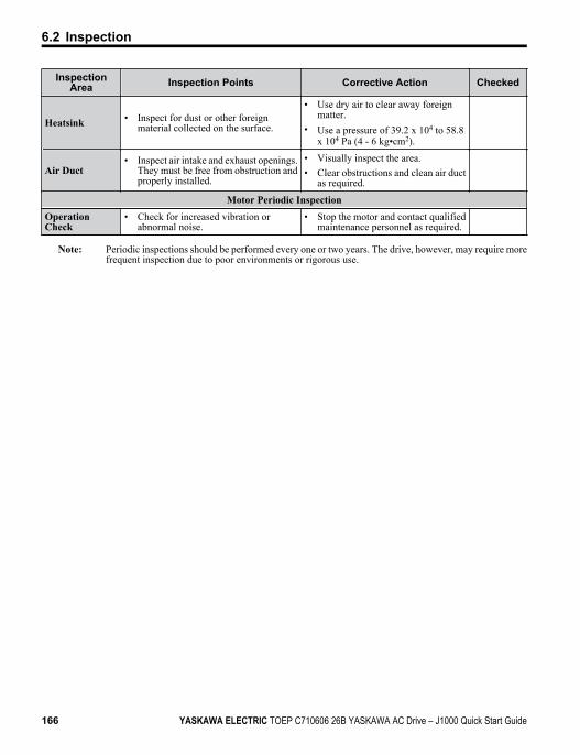
InspectionArea Inspection Points Corrective Action Checked
Heatsink • Inspect for dust or other foreignmaterial collected on the surface.
• Use dry air to clear away foreignmatter.
• Use a pressure of 39.2 x 10⁴ to 58.8x 10⁴ Pa (4 - 6 kg•cm2).
Air Duct• Inspect air intake and exhaust openings.
They must be free from obstruction andproperly installed.
• Visually inspect the area.• Clear obstructions and clean air duct
as required.
Motor Periodic InspectionOperationCheck
• Check for increased vibration orabnormal noise.
• Stop the motor and contact qualifiedmaintenance personnel as required.
Note: Periodic inspections should be performed every one or two years. The drive, however, may require morefrequent inspection due to poor environments or rigorous use.
6.2 Inspection
166 YASKAWA ELECTRIC TOEP C710606 26B YASKAWA AC Drive – J1000 Quick Start Guide
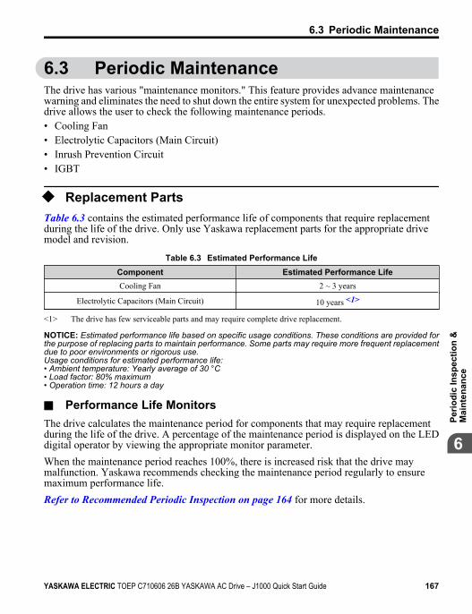
6.3 Periodic MaintenanceThe drive has various "maintenance monitors." This feature provides advance maintenancewarning and eliminates the need to shut down the entire system for unexpected problems. Thedrive allows the user to check the following maintenance periods.• Cooling Fan• Electrolytic Capacitors (Main Circuit)• Inrush Prevention Circuit• IGBT
u Replacement PartsTable 6.3 contains the estimated performance life of components that require replacementduring the life of the drive. Only use Yaskawa replacement parts for the appropriate drivemodel and revision.
Table 6.3 Estimated Performance LifeComponent Estimated Performance LifeCooling Fan 2 ~ 3 years
Electrolytic Capacitors (Main Circuit) 10 years <1>
<1> The drive has few serviceable parts and may require complete drive replacement.
NOTICE: Estimated performance life based on specific usage conditions. These conditions are provided forthe purpose of replacing parts to maintain performance. Some parts may require more frequent replacementdue to poor environments or rigorous use.Usage conditions for estimated performance life:• Ambient temperature: Yearly average of 30 °C• Load factor: 80% maximum• Operation time: 12 hours a day
n Performance Life MonitorsThe drive calculates the maintenance period for components that may require replacementduring the life of the drive. A percentage of the maintenance period is displayed on the LEDdigital operator by viewing the appropriate monitor parameter.When the maintenance period reaches 100%, there is increased risk that the drive maymalfunction. Yaskawa recommends checking the maintenance period regularly to ensuremaximum performance life.Refer to Recommended Periodic Inspection on page 164 for more details.
6.3 Periodic Maintenance
YASKAWA ELECTRIC TOEP C710606 26B YASKAWA AC Drive – J1000 Quick Start Guide 167
6Pe
riodi
c In
spec
tion
&M
aint
enan
ce
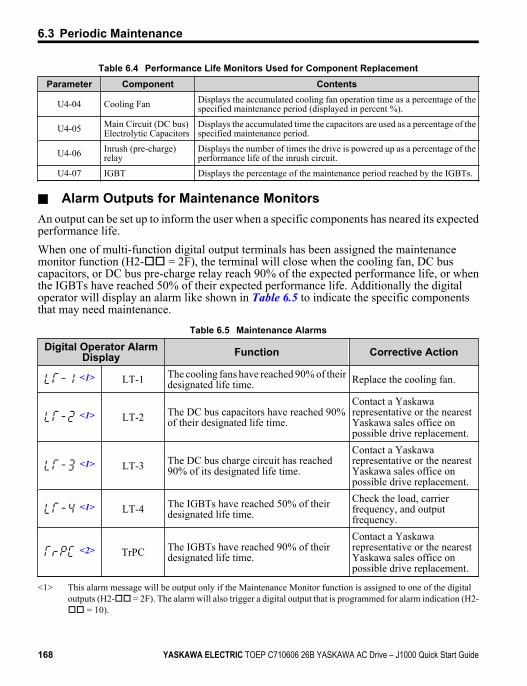
Table 6.4 Performance Life Monitors Used for Component ReplacementParameter Component Contents
U4-04 Cooling Fan Displays the accumulated cooling fan operation time as a percentage of thespecified maintenance period (displayed in percent %).
U4-05 Main Circuit (DC bus)Electrolytic Capacitors
Displays the accumulated time the capacitors are used as a percentage of thespecified maintenance period.
U4-06 Inrush (pre-charge)relay
Displays the number of times the drive is powered up as a percentage of theperformance life of the inrush circuit.
U4-07 IGBT Displays the percentage of the maintenance period reached by the IGBTs.
n Alarm Outputs for Maintenance MonitorsAn output can be set up to inform the user when a specific components has neared its expectedperformance life.When one of multi-function digital output terminals has been assigned the maintenancemonitor function (H2-oo = 2F), the terminal will close when the cooling fan, DC buscapacitors, or DC bus pre-charge relay reach 90% of the expected performance life, or whenthe IGBTs have reached 50% of their expected performance life. Additionally the digitaloperator will display an alarm like shown in Table 6.5 to indicate the specific componentsthat may need maintenance.
Table 6.5 Maintenance Alarms
Digital Operator AlarmDisplay Function Corrective Action
<1> LT-1 The cooling fans have reached 90% of theirdesignated life time. Replace the cooling fan.
<1> LT-2 The DC bus capacitors have reached 90%of their designated life time.
Contact a Yaskawarepresentative or the nearestYaskawa sales office onpossible drive replacement.
<1> LT-3 The DC bus charge circuit has reached90% of its designated life time.
Contact a Yaskawarepresentative or the nearestYaskawa sales office onpossible drive replacement.
<1> LT-4 The IGBTs have reached 50% of theirdesignated life time.
Check the load, carrierfrequency, and outputfrequency.
<2> TrPC The IGBTs have reached 90% of theirdesignated life time.
Contact a Yaskawarepresentative or the nearestYaskawa sales office onpossible drive replacement.
<1> This alarm message will be output only if the Maintenance Monitor function is assigned to one of the digitaloutputs (H2-oo = 2F). The alarm will also trigger a digital output that is programmed for alarm indication (H2-oo = 10).
6.3 Periodic Maintenance
168 YASKAWA ELECTRIC TOEP C710606 26B YASKAWA AC Drive – J1000 Quick Start Guide
<2> This alarm message will always be output, even if the Maintenance Monitor function is not assigned to any ofthe digital outputs (H2-oo = 2F). The alarm will also trigger a digital output that is programmed for alarmindication (H2-oo = 10).
n Related Drive ParametersUse parameters o4-03, o4-05, o4-07, and o4-09 to reset a Maintenance Monitor to zero afterreplacing a specific component. Refer to Parameter List on page 209 for details on parametersettings.NOTICE: If these parameters are not reset after the corresponding parts have been replaced, theMaintenance Monitor function will continue to count down the performance life from the value that was reachedwith the old part. If the Maintenance Monitor is not reset, the drive will not have the correct value of theperformance life for the new component.
6.3 Periodic Maintenance
YASKAWA ELECTRIC TOEP C710606 26B YASKAWA AC Drive – J1000 Quick Start Guide 169
6Pe
riodi
c In
spec
tion
&M
aint
enan
ce
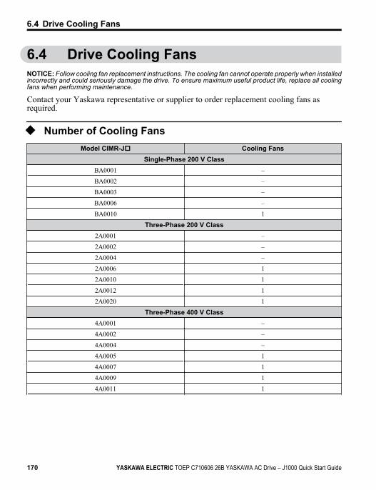
6.4 Drive Cooling FansNOTICE: Follow cooling fan replacement instructions. The cooling fan cannot operate properly when installedincorrectly and could seriously damage the drive. To ensure maximum useful product life, replace all coolingfans when performing maintenance.
Contact your Yaskawa representative or supplier to order replacement cooling fans asrequired.
u Number of Cooling FansModel CIMR-Jo Cooling Fans
Single-Phase 200 V ClassBA0001 –
BA0002 –
BA0003 –
BA0006 –
BA0010 1
Three-Phase 200 V Class2A0001 –
2A0002 –
2A0004 –
2A0006 1
2A0010 1
2A0012 1
2A0020 1
Three-Phase 400 V Class4A0001 –
4A0002 –
4A0004 –
4A0005 1
4A0007 1
4A0009 1
4A0011 1
6.4 Drive Cooling Fans
170 YASKAWA ELECTRIC TOEP C710606 26B YASKAWA AC Drive – J1000 Quick Start Guide
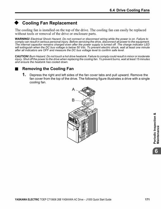
u Cooling Fan ReplacementThe cooling fan is installed on the top of the drive. The cooling fan can easily be replacedwithout tools or removal of the drive or enclosure parts.WARNING! Electrical Shock Hazard. Do not connect or disconnect wiring while the power is on. Failure tocomply can result in serious personal injury. Before servicing the drive, disconnect all power to the equipment.The internal capacitor remains charged even after the power supply is turned off. The charge indicator LEDwill extinguish when the DC bus voltage is below 50 Vdc. To prevent electric shock, wait at least one minuteafter all indicators are OFF and measure the DC bus voltage level to confirm safe level.
CAUTION! Burn Hazard. Do not touch a hot drive heatsink. Failure to comply could result in minor or moderateinjury. Shut off the power to the drive when replacing the cooling fan. To prevent burns, wait at least 15 minutesand ensure the heatsink has cooled down.
n Removing the Cooling Fan1. Depress the right and left sides of the fan cover tabs and pull upward. Remove the
fan cover from the top of the drive. The following figure illustrates a drive with a singlecooling fan.
A
B
6.4 Drive Cooling Fans
YASKAWA ELECTRIC TOEP C710606 26B YASKAWA AC Drive – J1000 Quick Start Guide 171
6Pe
riodi
c In
spec
tion
&M
aint
enan
ce
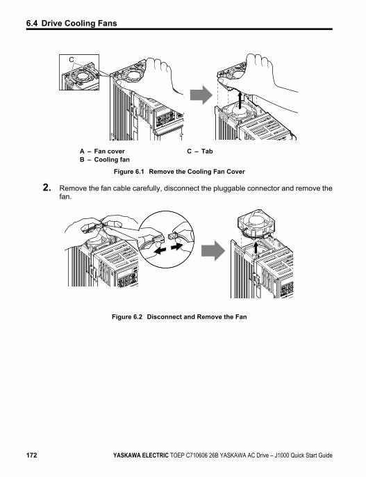
C
A – Fan coverB – Cooling fan
C – Tab
Figure 6.1 Remove the Cooling Fan Cover
2. Remove the fan cable carefully, disconnect the pluggable connector and remove thefan.
Figure 6.2 Disconnect and Remove the Fan
6.4 Drive Cooling Fans
172 YASKAWA ELECTRIC TOEP C710606 26B YASKAWA AC Drive – J1000 Quick Start Guide
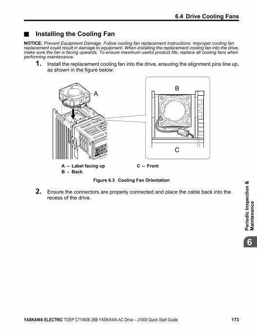
n Installing the Cooling FanNOTICE: Prevent Equipment Damage. Follow cooling fan replacement instructions. Improper cooling fanreplacement could result in damage to equipment. When installing the replacement cooling fan into the drive,make sure the fan is facing upwards. To ensure maximum useful product life, replace all cooling fans whenperforming maintenance.
1. Install the replacement cooling fan into the drive, ensuring the alignment pins line up,as shown in the figure below:
AB
C
A – Label facing upB – Back
C – Front
Figure 6.3 Cooling Fan Orientation
2. Ensure the connectors are properly connected and place the cable back into therecess of the drive.
6.4 Drive Cooling Fans
YASKAWA ELECTRIC TOEP C710606 26B YASKAWA AC Drive – J1000 Quick Start Guide 173
6Pe
riodi
c In
spec
tion
&M
aint
enan
ce
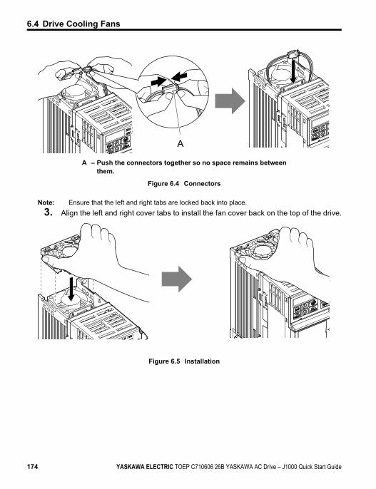
A
A – Push the connectors together so no space remains betweenthem.
Figure 6.4 Connectors
Note: Ensure that the left and right tabs are locked back into place.3. Align the left and right cover tabs to install the fan cover back on the top of the drive.
Figure 6.5 Installation
6.4 Drive Cooling Fans
174 YASKAWA ELECTRIC TOEP C710606 26B YASKAWA AC Drive – J1000 Quick Start Guide
Peripheral Devices& Options
This chapter explains the installation of available peripheraldevices and options for the drive.
7.1 SECTION SAFETY...........................................1767.2 DRIVE OPTIONS AND PERIPHERAL
DEVICES.........................................................1787.3 CONNECTING PERIPHERAL DEVICES...........1807.4 INSTALLING PERIPHERAL DEVICES..............1827.5 OPTIONS.........................................................196
7
YASKAWA ELECTRIC TOEP C710606 26B YASKAWA AC Drive – J1000 Quick Start Guide 175
7.1 Section Safety
DANGER
Electrical Shock HazardDo not connect or disconnect wiring while the power is on.Failure to comply will result in death or serious injury.Disconnect all power to the drive, wait at least one minute after all indicators are off, measurethe DC bus voltage to confirm safe level, and check for unsafe voltages before servicing toprevent electric shock. The internal capacitor remains charged even after the power supplyis turned off. The charge indicator LED will extinguish when the DC bus voltage is below50 Vdc.
WARNING
Electrical Shock HazardDo not operate equipment with covers removed.Failure to comply could result in death or serious injury.The diagrams in this section may show drives without covers or safety shields to showdetails. Be sure to reinstall covers or shields before operating the drives and run the drivesaccording to the instructions described in this manual.Do not remove covers or touch circuit boards while the power is on.Failure to comply could result in death or serious injury.Do not touch any terminals before the capacitors have fully discharged.Failure to comply could result in death or serious injury.Before wiring terminals, disconnect all power to the equipment. The internal capacitorremains charged even after the power supply is turned off. The charge indicator LED willextinguish when the DC bus voltage is below 50 Vdc. To prevent electric shock, wait atleast one minute after all indicators are off and measure the DC bus voltage level to confirmsafe level.Do not allow unqualified personnel to perform work on the drive.Failure to comply could result in death or serious injury.Installation, maintenance, inspection and servicing must be performed only by authorizedpersonnel familiar with installation, adjustment and maintenance of AC drives.
7.1 Section Safety
176 YASKAWA ELECTRIC TOEP C710606 26B YASKAWA AC Drive – J1000 Quick Start Guide
WARNINGDo not perform work on the drive while wearing loose clothing, jewelry or without eyeprotection.Failure to comply could result in death or serious injury.Remove all metal objects such as watches and rings, secure loose clothing and wear eyeprotection before beginning work on the drive.Always ground the motor-side grounding terminal.Improper equipment grounding could result in death or serious injury by contacting themotor case.Do not change wiring or remove option unit while power is running through the drive.Failure to comply could result in death or serious injury.Disconnect all power to the drive and check for unsafe voltages before servicing.Tighten all terminal screws to the specified tightening torque.Loose electrical connections could result in death or serious injury by fire due to overheatingof electrical connections.
NOTICE
Observe proper electrostatic discharge procedures (ESD) when handling the drive andcircuit boards.Failure to comply may result in ESD damage to the drive circuitry.Never connect or disconnect the motor from the drive while the drive is outputtingvoltage.Improper equipment sequencing could result in damage to the drive.
7.1 Section Safety
YASKAWA ELECTRIC TOEP C710606 26B YASKAWA AC Drive – J1000 Quick Start Guide 177
7Pe
riphe
ral D
evic
es &
Opt
ions
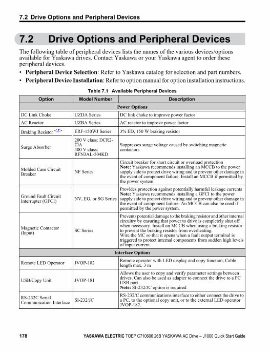
7.2 Drive Options and Peripheral DevicesThe following table of peripheral devices lists the names of the various devices/optionsavailable for Yaskawa drives. Contact Yaskawa or your Yaskawa agent to order theseperipheral devices.• Peripheral Device Selection: Refer to Yaskawa catalog for selection and part numbers.• Peripheral Device Installation: Refer to option manual for option installation instructions.
Table 7.1 Available Peripheral DevicesOption Model Number Description
Power OptionsDC Link Choke UZDA Series DC link choke to improve power factor
AC Reactor UZBA Series AC reactor to improve power factor
Braking Resistor <1> ERF-150WJ Series 3% ED, 150 W braking resistor
Surge Absorber200 V class: DCR2-oA400 V class:RFN3AL-504KD
Suppresses surge voltage caused by switching magneticcontactors
Molded Case CircuitBreaker NF Series
Circuit breaker for short circuit or overload protectionNote: Yaskawa recommends installing an MCCB to the powersupply side to protect drive wiring and to prevent other damage inthe event of component failure. Install an MCCB if permitted bythe power system.
Ground Fault CircuitInterrupter (GFCI) NV, EG, or SG Series
Provides protection against potentially harmful leakage currentsNote: Yaskawa recommends installing a GFCI to the powersupply side to protect drive wiring and to prevent other damage inthe event of component failure. An MCCB can also be used ifpermitted by the power system.
Magnetic Contactor(Input) SC Series
Prevents potential damage to the braking resistor and other internalcircuitry by ensuring that power to drive is completely shut offwhen necessary. Install an MCCB when using a braking resistorto prevent the braking resistor from overheating.Wire the MC so that it opens when a fault output terminal istriggered to protect internal components from sudden high levelsof input current.
Interface Options
Remote LED Operator JVOP-182 Remote operator with LED display and copy function; Cablelength max. 3 m
USB/Copy Unit JVOP-181Allows the user to copy and verify parameter settings betweendrives. Can also be used as adapter to connect the drive to a PCUSB port.Note: SI-232/JC option is required
RS-232C SerialCommunication Interface SI-232/JC
RS-232/C communications interface to either connect the drive toa PC, to the optional copy unit, or to the external LED operatorJVOP-182.
7.2 Drive Options and Peripheral Devices
178 YASKAWA ELECTRIC TOEP C710606 26B YASKAWA AC Drive – J1000 Quick Start Guide
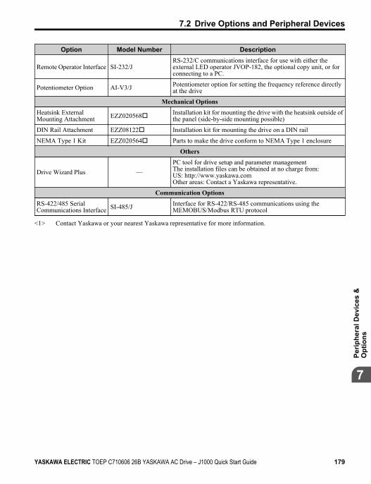
Option Model Number Description
Remote Operator Interface SI-232/JRS-232/C communications interface for use with either theexternal LED operator JVOP-182, the optional copy unit, or forconnecting to a PC.
Potentiometer Option AI-V3/J Potentiometer option for setting the frequency reference directlyat the drive
Mechanical OptionsHeatsink ExternalMounting Attachment EZZ020568o Installation kit for mounting the drive with the heatsink outside of
the panel (side-by-side mounting possible)
DIN Rail Attachment EZZ08122o Installation kit for mounting the drive on a DIN rail
NEMA Type 1 Kit EZZ020564o Parts to make the drive conform to NEMA Type 1 enclosure
Others
Drive Wizard Plus —PC tool for drive setup and parameter managementThe installation files can be obtained at no charge from:US: http://www.yaskawa.comOther areas: Contact a Yaskawa representative.
Communication OptionsRS-422/485 SerialCommunications Interface SI-485/J Interface for RS-422/RS-485 communications using the
MEMOBUS/Modbus RTU protocol
<1> Contact Yaskawa or your nearest Yaskawa representative for more information.
7.2 Drive Options and Peripheral Devices
YASKAWA ELECTRIC TOEP C710606 26B YASKAWA AC Drive – J1000 Quick Start Guide 179
7Pe
riphe
ral D
evic
es &
Opt
ions
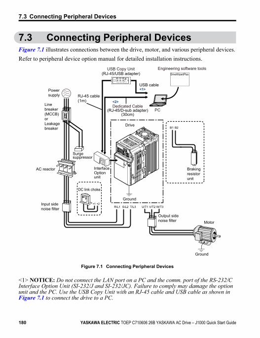
7.3 Connecting Peripheral DevicesFigure 7.1 illustrates connections between the drive, motor, and various peripheral devices.Refer to peripheral device option manual for detailed installation instructions.
Power supply
Line breaker(MCCB)orLeakagebreaker
AC reactor
Input sidenoise filter
DC link choke
Surgesuppressor
OptionInterface
unit
U/T1 V/T2 W/T3R/L1 S/L2+2+1
T/L3
Ground
Output sidenoise filter
Ground
Motor
B1 B2
DriveWizardPlus
Drive
Brakingresistorunit
CopyVerify
Read LOC
K
YAS
KAW
AJV
OP
-181
US
B C
opy
Uni
t
CO
ME
RR
PC
Engineering software tools
Dedicated Cable(RJ-45/D-sub adapter)
(30cm)
RJ-45 cable(1m)
USB Copy Unit(RJ-45/USB adapter)
USB cable<1>
<2>
Figure 7.1 Connecting Peripheral Devices
<1> NOTICE: Do not connect the LAN port on a PC and the comm. port of the RS-232/CInterface Option Unit (SI-232/J and SI-232/JC). Failure to comply may damage the optionunit and the PC. Use the USB Copy Unit with an RJ-45 cable and USB cable as shown inFigure 7.1 to connect the drive to a PC.
7.3 Connecting Peripheral Devices
180 YASKAWA ELECTRIC TOEP C710606 26B YASKAWA AC Drive – J1000 Quick Start Guide
<2> The Interface Option Unit can be directly connected to a PC with a D-sub 9-pin connector.Use a cable designed for PC use (Yaskawa part number WV103).
Note: If the drive is set to trigger an output terminal when performing a fault restart (L5-02 = 1), the powersupply will be shut off during fault restart as the drive outputs a fault signal. Keep this in mind whendesigning a wiring sequence to interrupt the power to the drive. The default setting for the drive is to nottrigger an output terminal that indicates a fault restart is being performed (L5-02 = 0).
7.3 Connecting Peripheral Devices
YASKAWA ELECTRIC TOEP C710606 26B YASKAWA AC Drive – J1000 Quick Start Guide 181
7Pe
riphe
ral D
evic
es &
Opt
ions
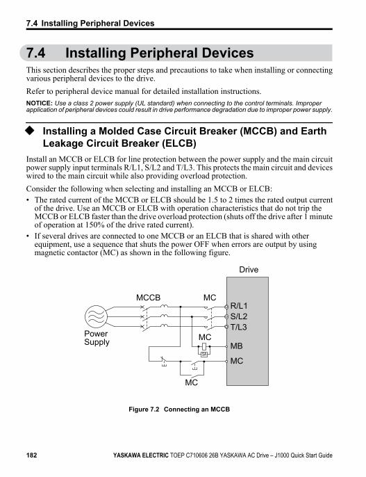
7.4 Installing Peripheral DevicesThis section describes the proper steps and precautions to take when installing or connectingvarious peripheral devices to the drive.Refer to peripheral device manual for detailed installation instructions.NOTICE: Use a class 2 power supply (UL standard) when connecting to the control terminals. Improperapplication of peripheral devices could result in drive performance degradation due to improper power supply.
u Installing a Molded Case Circuit Breaker (MCCB) and EarthLeakage Circuit Breaker (ELCB)
Install an MCCB or ELCB for line protection between the power supply and the main circuitpower supply input terminals R/L1, S/L2 and T/L3. This protects the main circuit and deviceswired to the main circuit while also providing overload protection.Consider the following when selecting and installing an MCCB or ELCB:• The rated current of the MCCB or ELCB should be 1.5 to 2 times the rated output current
of the drive. Use an MCCB or ELCB with operation characteristics that do not trip theMCCB or ELCB faster than the drive overload protection (shuts off the drive after 1 minuteof operation at 150% of the drive rated current).
• If several drives are connected to one MCCB or an ELCB that is shared with otherequipment, use a sequence that shuts the power OFF when errors are output by usingmagnetic contactor (MC) as shown in the following figure.
Drive
PowerSupply
R/L1
MB
MCCB MC
MC
MC
MC
S/L2T/L3
SA
Figure 7.2 Connecting an MCCB
7.4 Installing Peripheral Devices
182 YASKAWA ELECTRIC TOEP C710606 26B YASKAWA AC Drive – J1000 Quick Start Guide
WARNING! Electrical Shock Hazard. Disconnect the MCCB (or ELCB) and MC before wiring terminals.Failure to comply may result in serious injury or death.
u Application Precautions when Installing a GFCIDrive outputs generate high-frequency leakage current as a result of high-speed switching.Install a GFCI on the input side of the drive to switch off potentially harmful leakage current.Factors in determining leakage current:• Size of the AC drive• AC drive carrier frequency• Motor cable type and length• EMI/RFI filterIf the GFCI trips spuriously, consider changing these items or use a GFCI with a higher triplevel.
Note: Choose a GFCI designed specifically for an AC drive. The operation time should be at least 0.1 s withsensitivity amperage of at least 200 mA per drive. The output waveform of the drive may cause anincrease in leakage current. This may in turn cause the leakage breaker to malfunction. Increase thesensitivity amperage or lower the carrier frequency to correct the problem.
u Installing a Magnetic Contactor
n Disconnecting the Power SupplyThe drive should be shut off in the case of a fault in external equipment such as brakingresistors through use of a Magnetic Contactor (MC).NOTICE: Do not connect electromagnetic switches or MCs to the output motor circuits without propersequencing. Improper sequencing of output motor circuits may cause damage to the drive.
NOTICE: Install an MC on the input side of the drive when the drive should not automatically restart afterpower loss. To get the full performance life out of the electrolytic capacitors and circuit relays, refrain fromswitching the MC more than once every 30 minutes. Frequent use can damage the drive. Use the drive tostop and start the motor.
Note: 1. Install an MC to the drive output to prevent the drive from restarting automatically when the poweris restored after momentary power loss.
2. Set up a delay for the MC so that it does not open prematurely for the drive to continue operatingthrough momentary power loss.
7.4 Installing Peripheral Devices
YASKAWA ELECTRIC TOEP C710606 26B YASKAWA AC Drive – J1000 Quick Start Guide 183
7Pe
riphe
ral D
evic
es &
Opt
ions
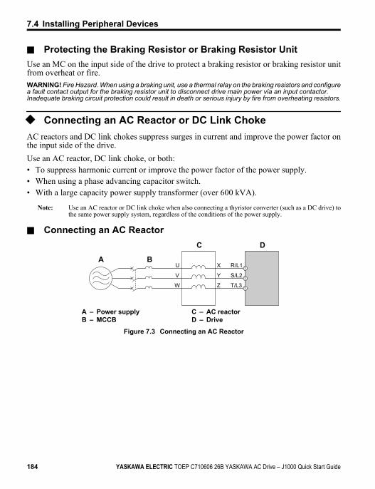
n Protecting the Braking Resistor or Braking Resistor UnitUse an MC on the input side of the drive to protect a braking resistor or braking resistor unitfrom overheat or fire.WARNING! Fire Hazard. When using a braking unit, use a thermal relay on the braking resistors and configurea fault contact output for the braking resistor unit to disconnect drive main power via an input contactor.Inadequate braking circuit protection could result in death or serious injury by fire from overheating resistors.
u Connecting an AC Reactor or DC Link ChokeAC reactors and DC link chokes suppress surges in current and improve the power factor onthe input side of the drive.Use an AC reactor, DC link choke, or both:• To suppress harmonic current or improve the power factor of the power supply.• When using a phase advancing capacitor switch.• With a large capacity power supply transformer (over 600 kVA).
Note: Use an AC reactor or DC link choke when also connecting a thyristor converter (such as a DC drive) tothe same power supply system, regardless of the conditions of the power supply.
n Connecting an AC Reactor
BA
C D
R/L1U
V
W
X
Y
Z
S/L2
T/L3
A – Power supplyB – MCCB
C – AC reactorD – Drive
Figure 7.3 Connecting an AC Reactor
7.4 Installing Peripheral Devices
184 YASKAWA ELECTRIC TOEP C710606 26B YASKAWA AC Drive – J1000 Quick Start Guide
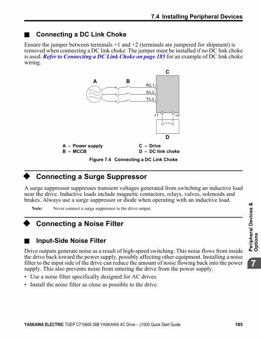
n Connecting a DC Link ChokeEnsure the jumper between terminals +1 and +2 (terminals are jumpered for shipment) isremoved when connecting a DC link choke. The jumper must be installed if no DC link chokeis used. Refer to Connecting a DC Link Choke on page 185 for an example of DC link chokewiring.
A
C
D
R/L1
+1 +2
B
S/L2
T/L3
A – Power supplyB – MCCB
C – DriveD – DC link choke
Figure 7.4 Connecting a DC Link Choke
u Connecting a Surge SuppressorA surge suppressor suppresses transient voltages generated from switching an inductive loadnear the drive. Inductive loads include magnetic contactors, relays, valves, solenoids andbrakes. Always use a surge suppressor or diode when operating with an inductive load.
Note: Never connect a surge suppressor to the drive output.
u Connecting a Noise Filter
n Input-Side Noise FilterDrive outputs generate noise as a result of high-speed switching. This noise flows from insidethe drive back toward the power supply, possibly affecting other equipment. Installing a noisefilter to the input side of the drive can reduce the amount of noise flowing back into the powersupply. This also prevents noise from entering the drive from the power supply.• Use a noise filter specifically designed for AC drives.• Install the noise filter as close as possible to the drive.
7.4 Installing Peripheral Devices
YASKAWA ELECTRIC TOEP C710606 26B YASKAWA AC Drive – J1000 Quick Start Guide 185
7Pe
riphe
ral D
evic
es &
Opt
ions
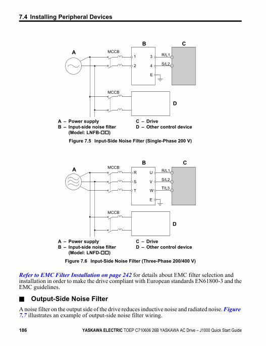
B C
D
A R/L11
2
3
4
E
MCCB
MCCB
S/L2
A – Power supplyB – Input-side noise filter
(Model: LNFB-oo)
C – DriveD – Other control device
Figure 7.5 Input-Side Noise Filter (Single-Phase 200 V)
C
D
AB
R/L1U
V
W
R
S
T
E
MCCB
MCCB
S/L2
T/L3
A – Power supplyB – Input-side noise filter
(Model: LNFD-oo)
C – DriveD – Other control device
Figure 7.6 Input-Side Noise Filter (Three-Phase 200/400 V)
Refer to EMC Filter Installation on page 242 for details about EMC filter selection andinstallation in order to make the drive compliant with European standards EN61800-3 and theEMC guidelines.
n Output-Side Noise FilterA noise filter on the output side of the drive reduces inductive noise and radiated noise. Figure 7.7 illustrates an example of output-side noise filter wiring.
7.4 Installing Peripheral Devices
186 YASKAWA ELECTRIC TOEP C710606 26B YASKAWA AC Drive – J1000 Quick Start Guide
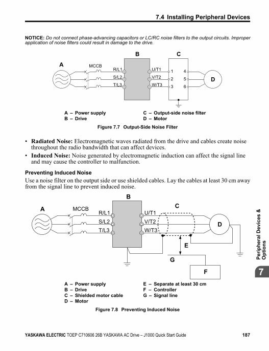
NOTICE: Do not connect phase-advancing capacitors or LC/RC noise filters to the output circuits. Improperapplication of noise filters could result in damage to the drive.
CB
A
D
R/L1MCCB
S/L2
T/L3
U/T1
V/T2
W/T3
1
2
3
4
5
6
A – Power supplyB – Drive
C – Output-side noise filterD – Motor
Figure 7.7 Output-Side Noise Filter
• Radiated Noise: Electromagnetic waves radiated from the drive and cables create noisethroughout the radio bandwidth that can affect devices.
• Induced Noise: Noise generated by electromagnetic induction can affect the signal lineand may cause the controller to malfunction.
Preventing Induced NoiseUse a noise filter on the output side or use shielded cables. Lay the cables at least 30 cm awayfrom the signal line to prevent induced noise.
B
A C
F
G
D
E
R/L1MCCB
S/L2T/L3
U/T1V/T2W/T3
A – Power supplyB – DriveC – Shielded motor cableD – Motor
E – Separate at least 30 cmF – ControllerG – Signal line
Figure 7.8 Preventing Induced Noise
7.4 Installing Peripheral Devices
YASKAWA ELECTRIC TOEP C710606 26B YASKAWA AC Drive – J1000 Quick Start Guide 187
7Pe
riphe
ral D
evic
es &
Opt
ions
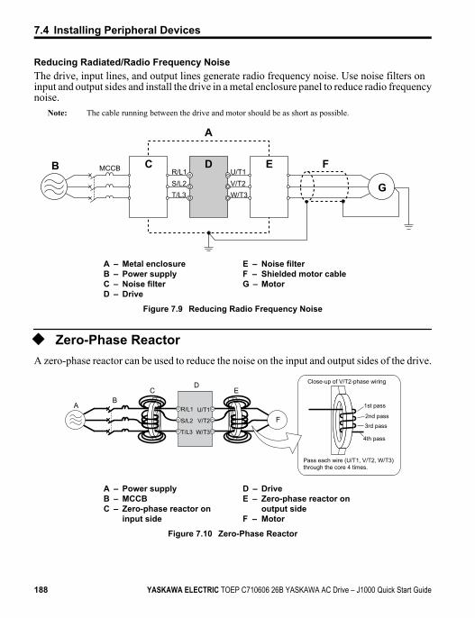
Reducing Radiated/Radio Frequency NoiseThe drive, input lines, and output lines generate radio frequency noise. Use noise filters oninput and output sides and install the drive in a metal enclosure panel to reduce radio frequencynoise.
Note: The cable running between the drive and motor should be as short as possible.
C EDB F
A
R/L1MCCB
S/L2T/L3
U/T1V/T2W/T3
G
A – Metal enclosureB – Power supplyC – Noise filterD – Drive
E – Noise filterF – Shielded motor cableG – Motor
Figure 7.9 Reducing Radio Frequency Noise
u Zero-Phase ReactorA zero-phase reactor can be used to reduce the noise on the input and output sides of the drive.
Close-up of V/T2-phase wiring
1st pass
4th pass
3rd pass
2nd pass
DE
F
CB
A
Pass each wire (U/T1, V/T2, W/T3) through the core 4 times.
R/L1
S/L2
T/L3
U/T1
V/T2
W/T3
A – Power supplyB – MCCBC – Zero-phase reactor on
input side
D – DriveE – Zero-phase reactor on
output sideF – Motor
Figure 7.10 Zero-Phase Reactor
7.4 Installing Peripheral Devices
188 YASKAWA ELECTRIC TOEP C710606 26B YASKAWA AC Drive – J1000 Quick Start Guide
u Installing Fuses on the Input SideAlways install input fuses to the input side of the as a protective measure against damagecaused by a short circuit.Refer to Factory Recommended Drive Branch Circuit Protection on page 251 for detailson input fuse selection.
u Attachment for External HeatsinkAn external attachment can be used to project the heatsink outside of an enclosure to ensurethat there is sufficient air circulation around the heatsink. This installation method still requiresa certain amount of airflow over the drive case. Refer to Output Current Derating Due to Ambient Temperature on page 207 if derating is required. Contact a Yaskawa salesrepresentative for more information.
u Noise Filter InstallationThis drive has undergone testing in conformance with IEC61800-5-1: 2007 and is incompliance with low voltage directives. Refer to EMC Guidelines Compliance on page 242 for information on selecting a noise filter.
u Installing a Motor Thermal Overload (oL) Relay on the DriveOutput
Motor thermal overload relays protect the motor by disconnecting power lines to the motordue to a motor overload condition.Install a motor thermal overload relay between the drive and motor:• When operating multiple motors on a single AC drive.• When using a power line bypass to operate the motor directly from the power line.It is not necessary to install a motor thermal overload relay when operating a single motorfrom a single AC drive. The AC drive has UL recognized electronic motor overload protectionbuilt into the drive software.
Note: Disable the motor protection function (L1-0 1 = “0”) when using an external motor thermal overloadrelay. The relay should shut off main power on the input side of the main circuit when triggered.
n General Precautions when Using Thermal Overload RelaysThe following application precautions should be considered when using motor thermaloverload relays on the output of AC drives in order to prevent nuisance trips or overheat ofthe motor at low speeds:• Low speed motor operation• Use of multiple motors on a single AC drive
7.4 Installing Peripheral Devices
YASKAWA ELECTRIC TOEP C710606 26B YASKAWA AC Drive – J1000 Quick Start Guide 189
7Pe
riphe
ral D
evic
es &
Opt
ions
• Motor cable length• Nuisance tripping resulting from high AC drive carrier frequency
Low Speed Operation and Motor Thermal oL RelaysGenerally, thermal relays are applied on general-purpose motors. When general-purposemotors are driven by AC drives, the motor current is approximately 5 ~ 10% greater than ifdriven by the commercial power supply. In addition, the cooling capacity of a motor with ashaft-driven fan decreases when operating at low speeds. Even if the load current is withinthe motor rated value, motor overheating may occur. A thermal relay cannot effectively protectthe motor due to the reduction of cooling at low speeds. For this reason, apply the ULrecognized electronic thermal overload protection function built into the drive wheneverpossible.UL recognized electronic thermal overload function of the drive: Speed-dependent heatcharacteristics are simulated using data from standard motors and force-ventilated motors.The motor is protected from overload using this function.
Using One Drive with Multiple MotorsTurn off the electronic thermal overload function. Please refer to the appropriate productinstruction manual to determine which parameter disables this function.The UL recognized electronic thermal overload function of the drive cannot be applied whenusing multiple motors on one drive.
Long Motor CablesWhen long motor cables and high carrier frequency are used, nuisance tripping of the thermalrelay may occur due to increased leakage current. Therefore, reduce the carrier frequency orincrease the tripping level of the thermal overload relay.
Nuisance Tripping Resulting from High AC Drive Carrier FrequencyCurrent waveforms generated by high carrier frequency PWM drives tend to create additionaltemperature rise in overload relays. Therefore, it may be necessary to increase the trip levelsetting when encountering nuisance triggering of the relay.WARNING! Fire Hazard. Confirm an actual motor overload condition is not present prior to increasing thethermal oL trip setting. Check local electrical codes before making adjustments to motor thermal overloadsettings.
u NEMA Type 1 KitWARNING! Fire Hazard. Provide sufficient cooling when installing the drive inside an enclosed panel orcabinet. Failure to comply could result in overheating and fire. When multiple drives are placed inside thesame enclosure panel, install proper cooling to ensure air entering the enclosure does not exceed 40 °C.
The optional NEMA Type 1 kit can be installed to raise the enclosure protection level of anIP20/Open-Chassis drive to NEMA Type 1. Drives with a NEMA Type 1 kit cannot beinstalled using side-by-side mounting unless the top cover is removed. The drive does notretain NEMA Type 1 integrity with the top cover removed. Refer to Installation Orientation and Spacing on page 30 for installation instructions.
7.4 Installing Peripheral Devices
190 YASKAWA ELECTRIC TOEP C710606 26B YASKAWA AC Drive – J1000 Quick Start Guide
n Installation EnvironmentTable 7.2 Installation Environment
Environment Conditions
AmbientTemperature
-10 °C to +40 °C (NEMA Type 1/wall-mounted enclosure)Drive reliability improves in environments without wide temperature fluctuations.When using an enclosure panel, install a cooling fan or air conditioner in the area to ensurethat the air temperature inside the enclosure does not exceed the specified levels.Do not allow ice to develop on the drive.
Refer to Installation Environment on page 29 for all other installation environment specifications.
7.4 Installing Peripheral Devices
YASKAWA ELECTRIC TOEP C710606 26B YASKAWA AC Drive – J1000 Quick Start Guide 191
7Pe
riphe
ral D
evic
es &
Opt
ions
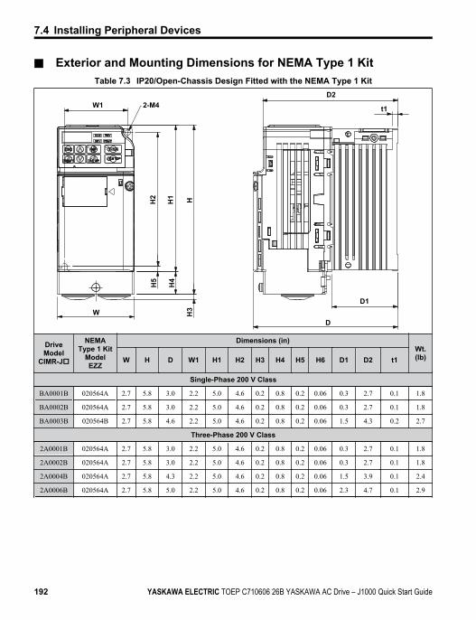
n Exterior and Mounting Dimensions for NEMA Type 1 KitTable 7.3 IP20/Open-Chassis Design Fitted with the NEMA Type 1 Kit
D1
t1
H1 HH2
H5
H4
H3W
D2
D
2-M4W1
DriveModel
CIMR-Jo
NEMAType 1 Kit
ModelEZZ
Dimensions (in)Wt.(lb)W H D W1 H1 H2 H3 H4 H5 H6 D1 D2 t1
Single-Phase 200 V Class
BA0001B 020564A 2.7 5.8 3.0 2.2 5.0 4.6 0.2 0.8 0.2 0.06 0.3 2.7 0.1 1.8
BA0002B 020564A 2.7 5.8 3.0 2.2 5.0 4.6 0.2 0.8 0.2 0.06 0.3 2.7 0.1 1.8
BA0003B 020564B 2.7 5.8 4.6 2.2 5.0 4.6 0.2 0.8 0.2 0.06 1.5 4.3 0.2 2.7
Three-Phase 200 V Class
2A0001B 020564A 2.7 5.8 3.0 2.2 5.0 4.6 0.2 0.8 0.2 0.06 0.3 2.7 0.1 1.8
2A0002B 020564A 2.7 5.8 3.0 2.2 5.0 4.6 0.2 0.8 0.2 0.06 0.3 2.7 0.1 1.8
2A0004B 020564A 2.7 5.8 4.3 2.2 5.0 4.6 0.2 0.8 0.2 0.06 1.5 3.9 0.1 2.4
2A0006B 020564A 2.7 5.8 5.0 2.2 5.0 4.6 0.2 0.8 0.2 0.06 2.3 4.7 0.1 2.9
7.4 Installing Peripheral Devices
192 YASKAWA ELECTRIC TOEP C710606 26B YASKAWA AC Drive – J1000 Quick Start Guide
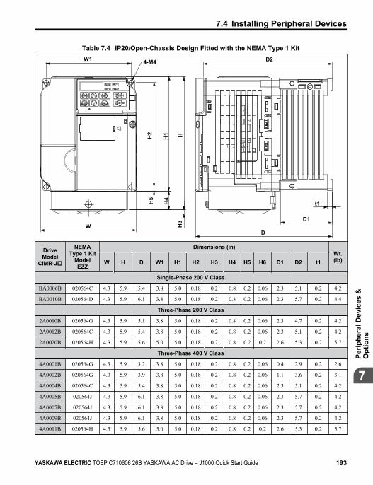
Table 7.4 IP20/Open-Chassis Design Fitted with the NEMA Type 1 Kit
4-M4W1
W
H5
H2
H4
HH
3
H1
D1
D2
D
t1
DriveModel
CIMR-Jo
NEMAType 1 Kit
ModelEZZ
Dimensions (in)Wt.(lb)W H D W1 H1 H2 H3 H4 H5 H6 D1 D2 t1
Single-Phase 200 V Class
BA0006B 020564C 4.3 5.9 5.4 3.8 5.0 0.18 0.2 0.8 0.2 0.06 2.3 5.1 0.2 4.2
BA0010B 020564D 4.3 5.9 6.1 3.8 5.0 0.18 0.2 0.8 0.2 0.06 2.3 5.7 0.2 4.4
Three-Phase 200 V Class
2A0010B 020564G 4.3 5.9 5.1 3.8 5.0 0.18 0.2 0.8 0.2 0.06 2.3 4.7 0.2 4.2
2A0012B 020564C 4.3 5.9 5.4 3.8 5.0 0.18 0.2 0.8 0.2 0.06 2.3 5.1 0.2 4.2
2A0020B 020564H 4.3 5.9 5.6 5.0 5.0 0.18 0.2 0.8 0.2 0.2 2.6 5.3 0.2 5.7
Three-Phase 400 V Class
4A0001B 020564G 4.3 5.9 3.2 3.8 5.0 0.18 0.2 0.8 0.2 0.06 0.4 2.9 0.2 2.6
4A0002B 020564G 4.3 5.9 3.9 3.8 5.0 0.18 0.2 0.8 0.2 0.06 1.1 3.6 0.2 3.1
4A0004B 020564C 4.3 5.9 5.4 3.8 5.0 0.18 0.2 0.8 0.2 0.06 2.3 5.1 0.2 4.2
4A0005B 020564J 4.3 5.9 6.1 3.8 5.0 0.18 0.2 0.8 0.2 0.06 2.3 5.7 0.2 4.2
4A0007B 020564J 4.3 5.9 6.1 3.8 5.0 0.18 0.2 0.8 0.2 0.06 2.3 5.7 0.2 4.2
4A0009B 020564J 4.3 5.9 6.1 3.8 5.0 0.18 0.2 0.8 0.2 0.06 2.3 5.7 0.2 4.2
4A0011B 020564H 4.3 5.9 5.6 5.0 5.0 0.18 0.2 0.8 0.2 0.2 2.6 5.3 0.2 5.7
7.4 Installing Peripheral Devices
YASKAWA ELECTRIC TOEP C710606 26B YASKAWA AC Drive – J1000 Quick Start Guide 193
7Pe
riphe
ral D
evic
es &
Opt
ions
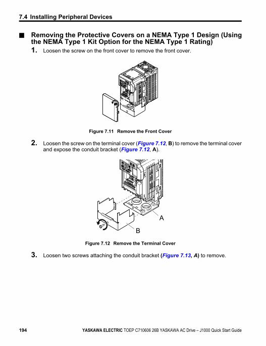
n Removing the Protective Covers on a NEMA Type 1 Design (Usingthe NEMA Type 1 Kit Option for the NEMA Type 1 Rating)1. Loosen the screw on the front cover to remove the front cover.
Figure 7.11 Remove the Front Cover
2. Loosen the screw on the terminal cover (Figure 7.12, B) to remove the terminal coverand expose the conduit bracket (Figure 7.12, A).
A
B
Figure 7.12 Remove the Terminal Cover
3. Loosen two screws attaching the conduit bracket (Figure 7.13, A) to remove.
7.4 Installing Peripheral Devices
194 YASKAWA ELECTRIC TOEP C710606 26B YASKAWA AC Drive – J1000 Quick Start Guide
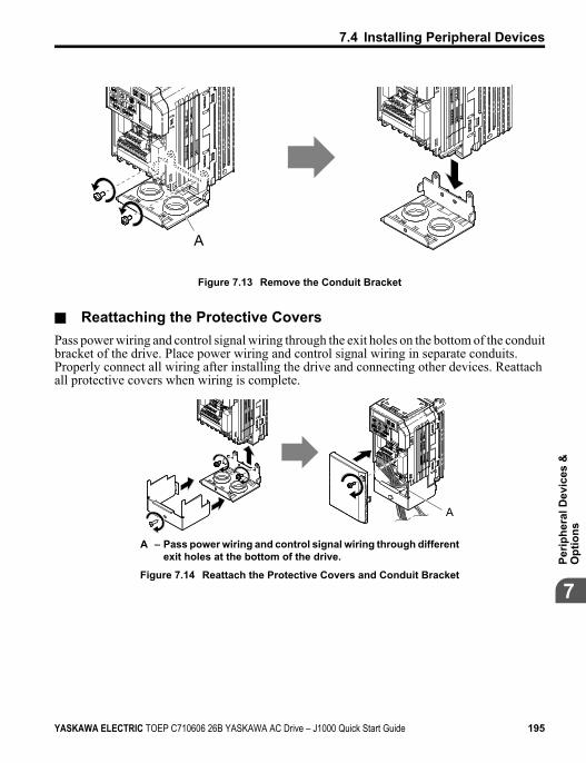
A
Figure 7.13 Remove the Conduit Bracket
n Reattaching the Protective CoversPass power wiring and control signal wiring through the exit holes on the bottom of the conduitbracket of the drive. Place power wiring and control signal wiring in separate conduits.Properly connect all wiring after installing the drive and connecting other devices. Reattachall protective covers when wiring is complete.
A
A – Pass power wiring and control signal wiring through differentexit holes at the bottom of the drive.
Figure 7.14 Reattach the Protective Covers and Conduit Bracket
7.4 Installing Peripheral Devices
YASKAWA ELECTRIC TOEP C710606 26B YASKAWA AC Drive – J1000 Quick Start Guide 195
7Pe
riphe
ral D
evic
es &
Opt
ions
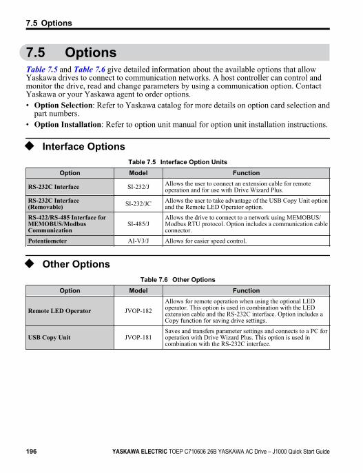
7.5 OptionsTable 7.5 and Table 7.6 give detailed information about the available options that allowYaskawa drives to connect to communication networks. A host controller can control andmonitor the drive, read and change parameters by using a communication option. ContactYaskawa or your Yaskawa agent to order options.• Option Selection: Refer to Yaskawa catalog for more details on option card selection and
part numbers.• Option Installation: Refer to option unit manual for option unit installation instructions.
u Interface OptionsTable 7.5 Interface Option Units
Option Model Function
RS-232C Interface SI-232/J Allows the user to connect an extension cable for remoteoperation and for use with Drive Wizard Plus.
RS-232C Interface(Removable) SI-232/JC Allows the user to take advantage of the USB Copy Unit option
and the Remote LED Operator option.
RS-422/RS-485 Interface forMEMOBUS/ModbusCommunication
SI-485/JAllows the drive to connect to a network using MEMOBUS/Modbus RTU protocol. Option includes a communication cableconnector.
Potentiometer AI-V3/J Allows for easier speed control.
u Other OptionsTable 7.6 Other Options
Option Model Function
Remote LED Operator JVOP-182Allows for remote operation when using the optional LEDoperator. This option is used in combination with the LEDextension cable and the RS-232C interface. Option includes aCopy function for saving drive settings.
USB Copy Unit JVOP-181Saves and transfers parameter settings and connects to a PC foroperation with Drive Wizard Plus. This option is used incombination with the RS-232C interface.
7.5 Options
196 YASKAWA ELECTRIC TOEP C710606 26B YASKAWA AC Drive – J1000 Quick Start Guide
Specifications
A.1 HEAVY DUTY AND NORMAL DUTY RATINGS........................................................................198
A.2 SINGLE/THREE-PHASE 200 V CLASSDRIVES...........................................................199
A.3 THREE-PHASE 400 V CLASS DRIVES............ 201A.4 DRIVE SPECIFICATIONS................................ 202A.5 DRIVE WATT LOSS DATA...............................205A.6 DRIVE DERATING DATA.................................207
Appendix: A
YASKAWA ELECTRIC TOEP C710606 26B YASKAWA AC Drive – J1000 Quick Start Guide 197
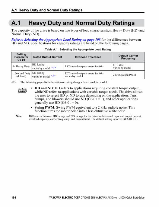
A.1 Heavy Duty and Normal Duty RatingsThe capacity of the drive is based on two types of load characteristics: Heavy Duty (HD) andNormal Duty (ND).Refer to Selecting the Appropriate Load Rating on page 198 for the differences betweenHD and ND. Specifications for capacity ratings are listed on the following pages.
Table A.1 Selecting the Appropriate Load RatingSetting
ParameterC6-01
Rated Output Current Overload Tolerance Default CarrierFrequency
0: Heavy DutyHD Ratingvaries by model <1> 150% rated output current for 60 s 8/10 kHz
varies by model
1: Normal Duty(default)
ND Ratingvaries by model <1>
120% rated output current for 60 svaries by model 2 kHz, Swing PWM
<1> The following pages list information on rating changes based on drive model.
TERMSTERMS• HD and ND: HD refers to applications requiring constant torque output,
while ND refers to applications with variable torque needs. The drive allowsthe user to select HD or ND torque depending on the application. Fans,pumps, and blowers should use ND (C6-01 = 1), and other applicationsgenerally use HD (C6-01 = 0).
• Swing PWM: Swing PWM equivalent to a 2 kHz audible noise. Thisfunction turns the motor noise into a less obtrusive white noise.
Note: Differences between HD ratings and ND ratings for the drive include rated input and output current,overload capacity, carrier frequency, and current limit. The default setting is for ND (C6-01 = 1).
A.1 Heavy Duty and Normal Duty Ratings
198 YASKAWA ELECTRIC TOEP C710606 26B YASKAWA AC Drive – J1000 Quick Start Guide
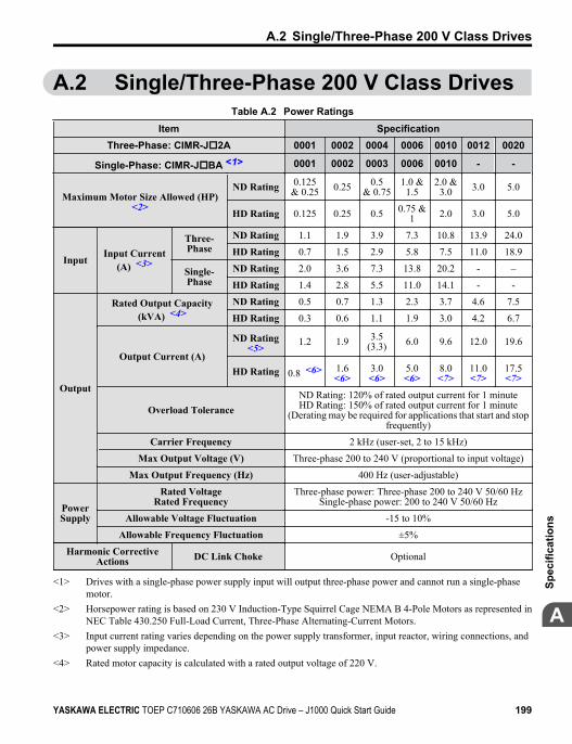
A.2 Single/Three-Phase 200 V Class DrivesTable A.2 Power Ratings
Item SpecificationThree-Phase: CIMR-Jo2A 0001 0002 0004 0006 0010 0012 0020
Single-Phase: CIMR-JoBA <1> 0001 0002 0003 0006 0010 - -
Maximum Motor Size Allowed (HP)<2>
ND Rating 0.125& 0.25 0.25 0.5
& 0.751.0 &
1.52.0 &
3.0 3.0 5.0
HD Rating 0.125 0.25 0.5 0.75 &1 2.0 3.0 5.0
InputInput Current
(A) <3>
Three-Phase
ND Rating 1.1 1.9 3.9 7.3 10.8 13.9 24.0
HD Rating 0.7 1.5 2.9 5.8 7.5 11.0 18.9
Single-Phase
ND Rating 2.0 3.6 7.3 13.8 20.2 - –
HD Rating 1.4 2.8 5.5 11.0 14.1 - -
Output
Rated Output Capacity(kVA) <4>
ND Rating 0.5 0.7 1.3 2.3 3.7 4.6 7.5
HD Rating 0.3 0.6 1.1 1.9 3.0 4.2 6.7
Output Current (A)
ND Rating<5> 1.2 1.9 3.5
(3.3) 6.0 9.6 12.0 19.6
HD Rating 0.8 <6> 1.6<6>
3.0<6>
5.0<6>
8.0<7>
11.0<7>
17.5<7>
Overload ToleranceND Rating: 120% of rated output current for 1 minuteHD Rating: 150% of rated output current for 1 minute
(Derating may be required for applications that start and stopfrequently)
Carrier Frequency 2 kHz (user-set, 2 to 15 kHz)
Max Output Voltage (V) Three-phase 200 to 240 V (proportional to input voltage)
Max Output Frequency (Hz) 400 Hz (user-adjustable)
PowerSupply
Rated VoltageRated Frequency
Three-phase power: Three-phase 200 to 240 V 50/60 HzSingle-phase power: 200 to 240 V 50/60 Hz
Allowable Voltage Fluctuation -15 to 10%
Allowable Frequency Fluctuation ±5%
Harmonic CorrectiveActions DC Link Choke Optional
<1> Drives with a single-phase power supply input will output three-phase power and cannot run a single-phasemotor.
<2> Horsepower rating is based on 230 V Induction-Type Squirrel Cage NEMA B 4-Pole Motors as represented inNEC Table 430.250 Full-Load Current, Three-Phase Alternating-Current Motors.
<3> Input current rating varies depending on the power supply transformer, input reactor, wiring connections, andpower supply impedance.
<4> Rated motor capacity is calculated with a rated output voltage of 220 V.
A.2 Single/Three-Phase 200 V Class Drives
YASKAWA ELECTRIC TOEP C710606 26B YASKAWA AC Drive – J1000 Quick Start Guide 199
A
Spec
ifica
tions
<5> Carrier frequency is set to 2 kHz (Swing PWM). Current derating is required in order to raise the carrierfrequency.
<6> Carrier frequency is set to 10 kHz. Current derating is required in order to raise the carrier frequency.<7> Carrier frequency is set to 8 kHz. Current derating is required in order to raise the carrier frequency.
Note: Differences between Heavy Duty (HD) ratings and Normal Duty (ND) ratings for the drive include ratedinput and output current, overload capacity, carrier frequency and current limit. Set parameter C6-01 to“0” for HD or “1” for ND (default).
A.2 Single/Three-Phase 200 V Class Drives
200 YASKAWA ELECTRIC TOEP C710606 26B YASKAWA AC Drive – J1000 Quick Start Guide
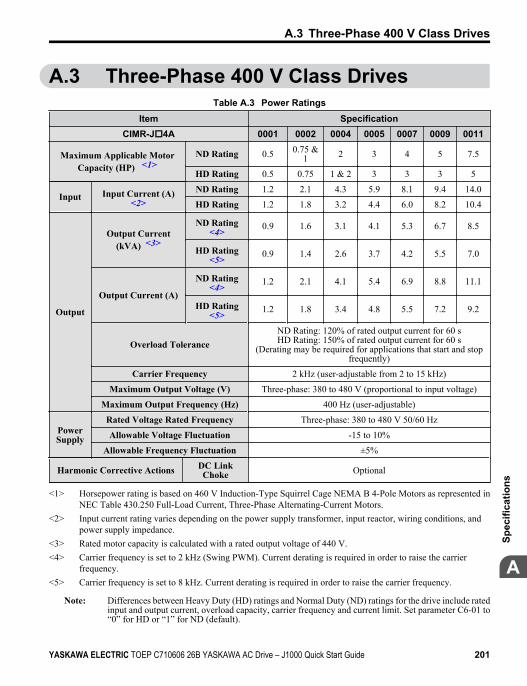
A.3 Three-Phase 400 V Class DrivesTable A.3 Power Ratings
Item SpecificationCIMR-Jo4A 0001 0002 0004 0005 0007 0009 0011
Maximum Applicable MotorCapacity (HP) <1>
ND Rating 0.5 0.75 &1 2 3 4 5 7.5
HD Rating 0.5 0.75 1 & 2 3 3 3 5
Input Input Current (A)<2>
ND Rating 1.2 2.1 4.3 5.9 8.1 9.4 14.0
HD Rating 1.2 1.8 3.2 4.4 6.0 8.2 10.4
Output
Output Current(kVA) <3>
ND Rating<4> 0.9 1.6 3.1 4.1 5.3 6.7 8.5
HD Rating<5> 0.9 1.4 2.6 3.7 4.2 5.5 7.0
Output Current (A)
ND Rating<4> 1.2 2.1 4.1 5.4 6.9 8.8 11.1
HD Rating<5> 1.2 1.8 3.4 4.8 5.5 7.2 9.2
Overload ToleranceND Rating: 120% of rated output current for 60 sHD Rating: 150% of rated output current for 60 s
(Derating may be required for applications that start and stopfrequently)
Carrier Frequency 2 kHz (user-adjustable from 2 to 15 kHz)
Maximum Output Voltage (V) Three-phase: 380 to 480 V (proportional to input voltage)
Maximum Output Frequency (Hz) 400 Hz (user-adjustable)
PowerSupply
Rated Voltage Rated Frequency Three-phase: 380 to 480 V 50/60 Hz
Allowable Voltage Fluctuation -15 to 10%
Allowable Frequency Fluctuation ±5%
Harmonic Corrective Actions DC LinkChoke Optional
<1> Horsepower rating is based on 460 V Induction-Type Squirrel Cage NEMA B 4-Pole Motors as represented inNEC Table 430.250 Full-Load Current, Three-Phase Alternating-Current Motors.
<2> Input current rating varies depending on the power supply transformer, input reactor, wiring conditions, andpower supply impedance.
<3> Rated motor capacity is calculated with a rated output voltage of 440 V.<4> Carrier frequency is set to 2 kHz (Swing PWM). Current derating is required in order to raise the carrier
frequency.<5> Carrier frequency is set to 8 kHz. Current derating is required in order to raise the carrier frequency.
Note: Differences between Heavy Duty (HD) ratings and Normal Duty (ND) ratings for the drive include ratedinput and output current, overload capacity, carrier frequency and current limit. Set parameter C6-01 to“0” for HD or “1” for ND (default).
A.3 Three-Phase 400 V Class Drives
YASKAWA ELECTRIC TOEP C710606 26B YASKAWA AC Drive – J1000 Quick Start Guide 201
A
Spec
ifica
tions
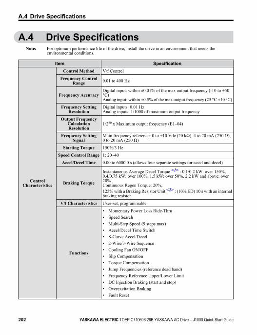
A.4 Drive SpecificationsNote: For optimum performance life of the drive, install the drive in an environment that meets the
environmental conditions.
Item Specification
ControlCharacteristics
Control Method V/f Control
Frequency ControlRange 0.01 to 400 Hz
Frequency AccuracyDigital input: within ±0.01% of the max output frequency (-10 to +50°C)Analog input: within ±0.5% of the max output frequency (25 °C ±10 °C)
Frequency SettingResolution
Digital inputs: 0.01 HzAnalog inputs: 1/1000 of maximum output frequency
Output FrequencyCalculationResolution
1/220 x Maximum output frequency (E1–04)
Frequency SettingSignal
Main frequency reference: 0 to +10 Vdc (20 kΩ), 4 to 20 mA (250 Ω),0 to 20 mA (250 Ω)
Starting Torque 150%/3 Hz
Speed Control Range 1: 20~40
Accel/Decel Time 0.00 to 6000.0 s (allows four separate settings for accel and decel)
Braking Torque
Instantaneous Average Decel Torque <1> : 0.1/0.2 kW: over 150%,0.4/0.75 kW: over 100%, 1.5 kW: over 50%, 2.2 kW and above: over20%Continuous Regen Torque: 20%,125% with a Braking Resistor Unit <2> : (10% ED) 10 s with an internalbraking resistor.
V/f Characteristics User-set, programmable.
Functions
• Momentary Power Loss Ride-Thru• Speed Search• Multi-Step Speed (9 steps max)• Accel/Decel Time Switch• S-Curve Accel/Decel• 2-Wire/3-Wire Sequence• Cooling Fan ON/OFF• Slip Compensation• Torque Compensation• Jump Frequencies (reference dead band)• Frequency Reference Upper/Lower Limit• DC Injection Braking (start and stop)• Overexcitation Braking• Fault Reset
A.4 Drive Specifications
202 YASKAWA ELECTRIC TOEP C710606 26B YASKAWA AC Drive – J1000 Quick Start Guide
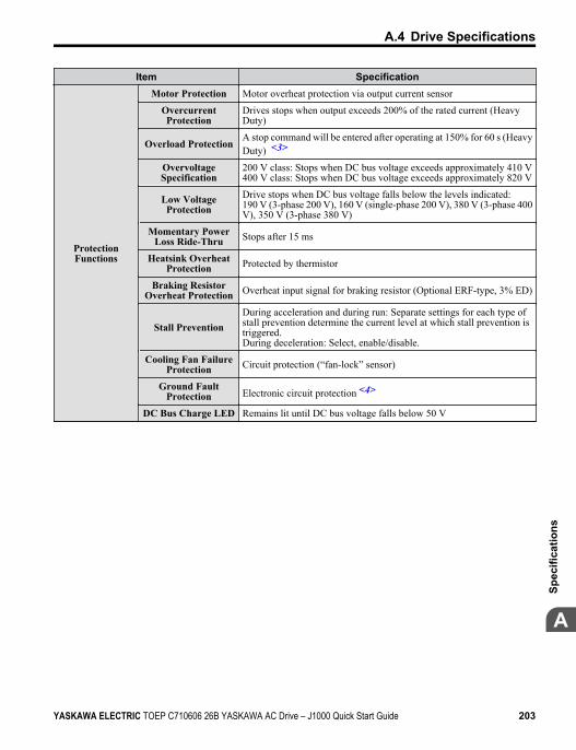
Item Specification
ProtectionFunctions
Motor Protection Motor overheat protection via output current sensor
OvercurrentProtection
Drives stops when output exceeds 200% of the rated current (HeavyDuty)
Overload ProtectionA stop command will be entered after operating at 150% for 60 s (HeavyDuty) <3>
OvervoltageSpecification
200 V class: Stops when DC bus voltage exceeds approximately 410 V400 V class: Stops when DC bus voltage exceeds approximately 820 V
Low VoltageProtection
Drive stops when DC bus voltage falls below the levels indicated:190 V (3-phase 200 V), 160 V (single-phase 200 V), 380 V (3-phase 400V), 350 V (3-phase 380 V)
Momentary PowerLoss Ride-Thru Stops after 15 ms
Heatsink OverheatProtection Protected by thermistor
Braking ResistorOverheat Protection Overheat input signal for braking resistor (Optional ERF-type, 3% ED)
Stall PreventionDuring acceleration and during run: Separate settings for each type ofstall prevention determine the current level at which stall prevention istriggered.During deceleration: Select, enable/disable.
Cooling Fan FailureProtection Circuit protection (“fan-lock” sensor)
Ground FaultProtection Electronic circuit protection <4>
DC Bus Charge LED Remains lit until DC bus voltage falls below 50 V
A.4 Drive Specifications
YASKAWA ELECTRIC TOEP C710606 26B YASKAWA AC Drive – J1000 Quick Start Guide 203
A
Spec
ifica
tions
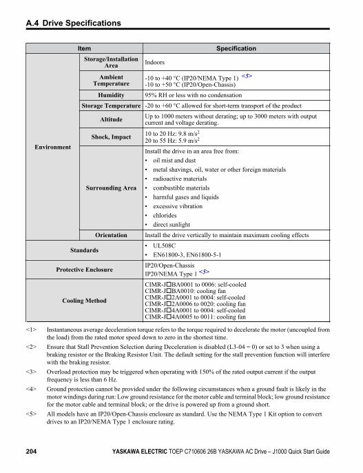
Item Specification
Environment
Storage/InstallationArea Indoors
AmbientTemperature
-10 to +40 °C (IP20/NEMA Type 1) <5>-10 to +50 °C (IP20/Open-Chassis)
Humidity 95% RH or less with no condensation
Storage Temperature -20 to +60 °C allowed for short-term transport of the product
Altitude Up to 1000 meters without derating; up to 3000 meters with outputcurrent and voltage derating.
Shock, Impact 10 to 20 Hz: 9.8 m/s2
20 to 55 Hz: 5.9 m/s2
Surrounding Area
Install the drive in an area free from:• oil mist and dust• metal shavings, oil, water or other foreign materials• radioactive materials• combustible materials• harmful gases and liquids• excessive vibration• chlorides• direct sunlight
Orientation Install the drive vertically to maintain maximum cooling effects
Standards• UL508C• EN61800-3, EN61800-5-1
Protective EnclosureIP20/Open-ChassisIP20/NEMA Type 1 <5>
Cooling Method
CIMR-JoBA0001 to 0006: self-cooledCIMR-JoBA0010: cooling fanCIMR-Jo2A0001 to 0004: self-cooledCIMR-Jo2A0006 to 0020: cooling fanCIMR-Jo4A0001 to 0004: self-cooledCIMR-Jo4A0005 to 0011: cooling fan
<1> Instantaneous average deceleration torque refers to the torque required to decelerate the motor (uncoupled fromthe load) from the rated motor speed down to zero in the shortest time.
<2> Ensure that Stall Prevention Selection during Deceleration is disabled (L3-04 = 0) or set to 3 when using abraking resistor or the Braking Resistor Unit. The default setting for the stall prevention function will interferewith the braking resistor.
<3> Overload protection may be triggered when operating with 150% of the rated output current if the outputfrequency is less than 6 Hz.
<4> Ground protection cannot be provided under the following circumstances when a ground fault is likely in themotor windings during run: Low ground resistance for the motor cable and terminal block; low ground resistancefor the motor cable and terminal block; or the drive is powered up from a ground short.
<5> All models have an IP20/Open-Chassis enclosure as standard. Use the NEMA Type 1 Kit option to convertdrives to an IP20/NEMA Type 1 enclosure rating.
A.4 Drive Specifications
204 YASKAWA ELECTRIC TOEP C710606 26B YASKAWA AC Drive – J1000 Quick Start Guide
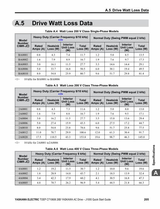
A.5 Drive Watt Loss DataTable A.4 Watt Loss 200 V Class Single-Phase Models
ModelNumber
CIMR-Jo
Heavy Duty (Carrier Frequency 8/10 kHz)<1> Normal Duty (Swing PWM equal 2 kHz)
RatedAmps (A)
HeatsinkLoss (W)
InteriorUnit Loss
(W)Total
Loss (W)Rated
Amps (A)HeatsinkLoss (W)
InteriorUnit Loss
(W)Total
Loss (W)
BA0001 0.8 4.3 7.4 11.7 1.2 5.0 8.5 13.5
BA0002 1.6 7.9 8.9 16.7 1.9 7.6 9.7 17.3
BA0003 3.0 16.1 11.5 27.7 3.3 14.6 14.4 29.1
BA0006 5.0 33.7 16.8 50.5 6.0 30.1 19.4 49.5
BA0010 8.0 54.8 25.9 80.7 9.6 51.7 29.8 81.4
<1> 10 kHz for BA0001 to BA0006
Table A.5 Watt Loss 200 V Class Three-Phase Models
ModelNumber
CIMR-Jo
Heavy Duty (Carrier Frequency 8/10 kHz)<1> Normal Duty (Swing PWM equal 2 kHz)
RatedAmps (A)
HeatsinkLoss (W)
InteriorUnit Loss
(W)Total
Loss (W)Rated
Amps (A)HeatsinkLoss (W)
InteriorUnit Loss
(W)Total
Loss (W)
2A0001 0.8 4.3 7.3 11.6 1.2 5.0 8.0 13.0
2A0002 1.6 7.9 8.8 16.7 1.9 7.6 9.5 17.1
2A0004 3.0 16.2 11.5 27.7 3.5 15.8 13.6 29.4
2A0006 5.0 27.4 15.9 43.3 6.0 27.5 17.2 44.7
2A0010 8.0 54.8 23.8 78.6 9.6 51.7 25.8 77.5
2A0012 11.0 70.7 29.9 100.6 12.0 61.3 30.4 91.7
2A0020 17.5 110.5 43.3 153.8 19.6 98.7 46.3 145.0
<1> 10 kHz for 2A0001 to2A0006
Table A.6 Watt Loss 400 V Class Three-Phase Models
ModelNumber
CIMR-Jo
Heavy Duty (Carrier Frequency 8 kHz) Normal Duty (Swing PWM equal 2 kHz)
RatedAmps (A)
HeatsinkLoss (W)
InteriorUnit Loss
(W)Total
Loss (W)Rated
Amps (A)HeatsinkLoss (W)
InteriorUnit Loss
(W)Total
Loss (W)
4A0001 1.2 19.2 11.5 30.7 1.2 10.0 9.6 19.6
4A0002 1.8 28.9 14.8 43.7 2.1 18.5 13.9 32.4
4A0004 3.4 42.3 17.9 60.2 4.1 30.5 16.8 47.3
4A0005 4.8 70.7 26.2 96.9 5.4 44.5 21.8 66.3
A.5 Drive Watt Loss Data
YASKAWA ELECTRIC TOEP C710606 26B YASKAWA AC Drive – J1000 Quick Start Guide 205
A
Spec
ifica
tions
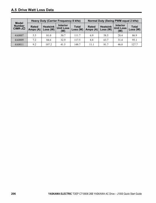
ModelNumber
CIMR-Jo
Heavy Duty (Carrier Frequency 8 kHz) Normal Duty (Swing PWM equal 2 kHz)
RatedAmps (A)
HeatsinkLoss (W)
InteriorUnit Loss
(W)Total
Loss (W)Rated
Amps (A)HeatsinkLoss (W)
InteriorUnit Loss
(W)Total
Loss (W)
4A0007 5.5 81.0 30.7 111.7 6.9 58.5 28.4 86.9
4A0009 7.2 84.6 32.9 117.5 8.8 63.7 31.4 95.1
4A0011 9.2 107.2 41.5 148.7 11.1 81.7 46.0 127.7
A.5 Drive Watt Loss Data
206 YASKAWA ELECTRIC TOEP C710606 26B YASKAWA AC Drive – J1000 Quick Start Guide
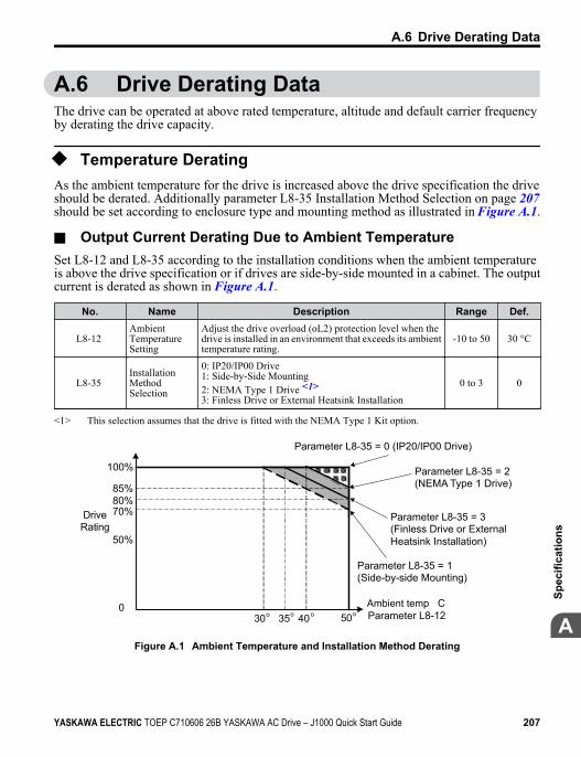
A.6 Drive Derating DataThe drive can be operated at above rated temperature, altitude and default carrier frequencyby derating the drive capacity.
u Temperature DeratingAs the ambient temperature for the drive is increased above the drive specification the driveshould be derated. Additionally parameter L8-35 Installation Method Selection on page 207should be set according to enclosure type and mounting method as illustrated in Figure A.1.
n Output Current Derating Due to Ambient TemperatureSet L8-12 and L8-35 according to the installation conditions when the ambient temperatureis above the drive specification or if drives are side-by-side mounted in a cabinet. The outputcurrent is derated as shown in Figure A.1.
No. Name Description Range Def.
L8-12 AmbientTemperatureSetting
Adjust the drive overload (oL2) protection level when thedrive is installed in an environment that exceeds its ambienttemperature rating.
-10 to 50 30 °C
L8-35 InstallationMethodSelection
0: IP20/IP00 Drive1: Side-by-Side Mounting2: NEMA Type 1 Drive <1>3: Finless Drive or External Heatsink Installation
0 to 3 0
<1> This selection assumes that the drive is fitted with the NEMA Type 1 Kit option.
40 500
30 o35
50%
70%80%85%
100%
ooo
Drive Rating
Ambient temp C Parameter L8-12
Parameter L8-35 = 0 (IP20/IP00 Drive)
Parameter L8-35 = 2 (NEMA Type 1 Drive)
Parameter L8-35 = 1 (Side-by-side Mounting)
Parameter L8-35 = 3 (Finless Drive or ExternalHeatsink Installation)
Figure A.1 Ambient Temperature and Installation Method Derating
A.6 Drive Derating Data
YASKAWA ELECTRIC TOEP C710606 26B YASKAWA AC Drive – J1000 Quick Start Guide 207
A
Spec
ifica
tions
u Altitude DeratingThe drive standard ratings are valid for an installation altitude up to 1000 m. If the altitudeexceeds 1000 m, both the drive input voltage and the rated output current must be derated for1% per 100 m. The maximum altitude is 3000 m.
A.6 Drive Derating Data
208 YASKAWA ELECTRIC TOEP C710606 26B YASKAWA AC Drive – J1000 Quick Start Guide

Parameter ListThis appendix contains a full listing of all parameters and settingsavailable in the drive.
B.1 PARAMETER GROUPS...................................210B.2 PARAMETER TABLE......................................211B.3 DEFAULTS BY DRIVE MODEL AND DUTY
RATING ND/HD...............................................234
Appendix: B
YASKAWA ELECTRIC TOEP C710606 26B YASKAWA AC Drive – J1000 Quick Start Guide 209
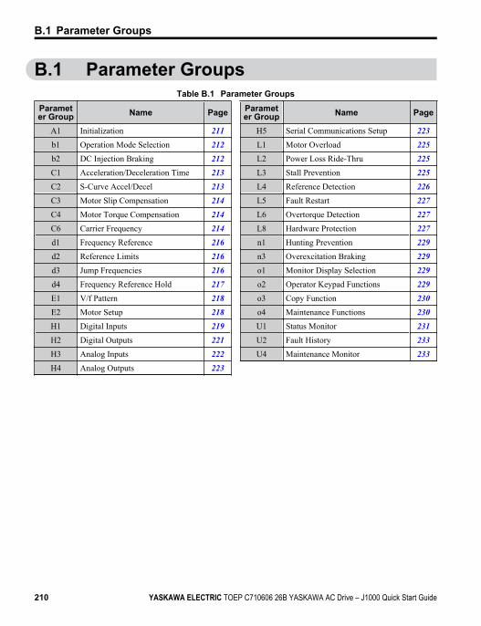
B.1 Parameter GroupsTable B.1 Parameter Groups
Parameter Group Name Page
A1 Initialization 211b1 Operation Mode Selection 212b2 DC Injection Braking 212C1 Acceleration/Deceleration Time 213C2 S-Curve Accel/Decel 213C3 Motor Slip Compensation 214C4 Motor Torque Compensation 214C6 Carrier Frequency 214d1 Frequency Reference 216d2 Reference Limits 216d3 Jump Frequencies 216d4 Frequency Reference Hold 217E1 V/f Pattern 218E2 Motor Setup 218H1 Digital Inputs 219H2 Digital Outputs 221H3 Analog Inputs 222H4 Analog Outputs 223
Parameter Group Name Page
H5 Serial Communications Setup 223L1 Motor Overload 225L2 Power Loss Ride-Thru 225L3 Stall Prevention 225L4 Reference Detection 226L5 Fault Restart 227L6 Overtorque Detection 227L8 Hardware Protection 227n1 Hunting Prevention 229n3 Overexcitation Braking 229o1 Monitor Display Selection 229o2 Operator Keypad Functions 229o3 Copy Function 230o4 Maintenance Functions 230U1 Status Monitor 231U2 Fault History 233U4 Maintenance Monitor 233
B.1 Parameter Groups
210 YASKAWA ELECTRIC TOEP C710606 26B YASKAWA AC Drive – J1000 Quick Start Guide
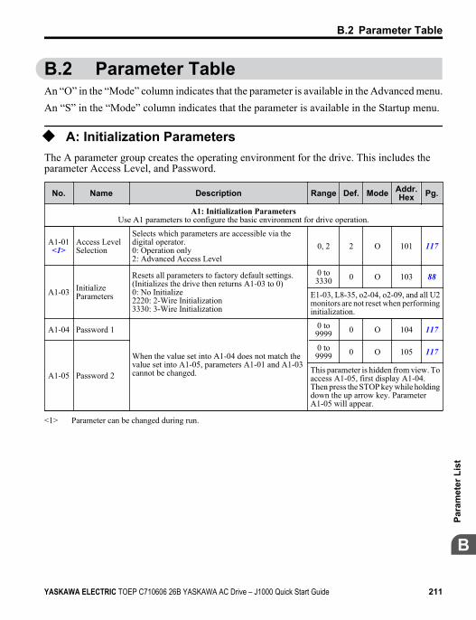
B.2 Parameter TableAn “O” in the “Mode” column indicates that the parameter is available in the Advanced menu.An “S” in the “Mode” column indicates that the parameter is available in the Startup menu.
u A: Initialization ParametersThe A parameter group creates the operating environment for the drive. This includes theparameter Access Level, and Password.
No. Name Description Range Def. Mode Addr.Hex Pg.
A1: Initialization ParametersUse A1 parameters to configure the basic environment for drive operation.
A1-01<1>
Access LevelSelection
Selects which parameters are accessible via thedigital operator.0: Operation only2: Advanced Access Level
0, 2 2 O 101 117
A1-03 InitializeParameters
Resets all parameters to factory default settings.(Initializes the drive then returns A1-03 to 0)0: No Initialize2220: 2-Wire Initialization3330: 3-Wire Initialization
0 to3330 0 O 103 88
E1-03, L8-35, o2-04, o2-09, and all U2monitors are not reset when performinginitialization.
A1-04 Password 1
When the value set into A1-04 does not match thevalue set into A1-05, parameters A1-01 and A1-03cannot be changed.
0 to9999 0 O 104 117
A1-05 Password 2
0 to9999 0 O 105 117
This parameter is hidden from view. Toaccess A1-05, first display A1-04.Then press the STOP key while holdingdown the up arrow key. ParameterA1-05 will appear.
<1> Parameter can be changed during run.
B.2 Parameter Table
YASKAWA ELECTRIC TOEP C710606 26B YASKAWA AC Drive – J1000 Quick Start Guide 211
B
Para
met
er L
ist
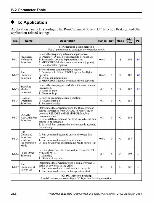
u b: ApplicationApplication parameters configure the Run Command Source, DC Injection Braking, and otherapplication-related settings.
No. Name Description Range Def. Mode Addr.Hex Pg.
b1: Operation Mode SelectionUse b1 parameters to configure the operation mode.
b1-01FrequencyReferenceSelection
Selects the frequency reference input source.0: Operator - Digital preset speed d1-01 to d1-081: Terminals - Analog input terminal A12: MEMOBUS/Modbus communications (option)3: Potentiometer (option)
0 to 3 1 S 180 88
b1-02RunCommandSelection
Selects the run command input source.0: Operator - RUN and STOP keys on the digitaloperator1: Digital input terminals2: MEMOBUS/Modbus communications (option)
0 to 2 1 S 181 90
b1-03StoppingMethodSelection
Selects the stopping method when the run commandis removed.0: Ramp to Stop1: Coast to Stop
0, 1 0 S 182 92
b1-04ReverseOperationSelection
Permits or prohibits reverse operation.0: Reverse enabled.1: Reverse disabled.
0, 1 0 O 183 –
b1-07LOCAL/REMOTE RunSelection
Determines the operation when the Run commandsource is switched from LOCAL to REMOTE orbetween REMOTE and MEMOBUS/Modbuscommunication.0: External Run command has to be cycled at the newsource to be activated.1: External Run command at new source is acceptedimmediately.
0, 1 0 O 186 –
b1-08
RunCommandSelectionwhile inProgrammingMode
0: Run command accepted only in the operationmenu.1: Run command accepted in all menus.2: Prohibit entering Programming Mode during Run
0 to 2 0 O 187 –
b1-14 Phase OrderSelection
Sets the phase order for drive output terminals U/T1,V/T2 and W/T3.0 : Standard1 : Switch phase order
0, 1 0 O 1C3 –
b1-17RunCommand atPower Up
Determines the operation when a Run command isactive at power up of the drive.0: Run command not issued, needs to be cycled1: Run command issued, motor operation start
0, 1 0 O 1C6 –
b2: DC Injection BrakingUse b2 parameters to configure DC Injection Braking operation
B.2 Parameter Table
212 YASKAWA ELECTRIC TOEP C710606 26B YASKAWA AC Drive – J1000 Quick Start Guide
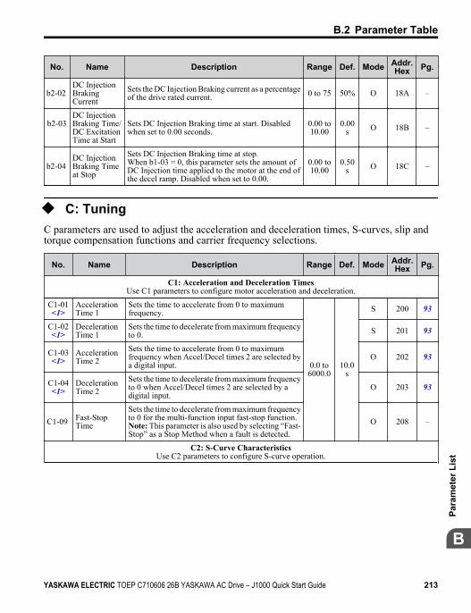
No. Name Description Range Def. Mode Addr.Hex Pg.
b2-02 DC InjectionBrakingCurrent
Sets the DC Injection Braking current as a percentageof the drive rated current. 0 to 75 50% O 18A –
b2-03DC InjectionBraking Time/DC ExcitationTime at Start
Sets DC Injection Braking time at start. Disabledwhen set to 0.00 seconds.
0.00 to10.00
0.00s O 18B –
b2-04 DC InjectionBraking Timeat Stop
Sets DC Injection Braking time at stop.When b1-03 = 0, this parameter sets the amount ofDC Injection time applied to the motor at the end ofthe decel ramp. Disabled when set to 0.00.
0.00 to10.00
0.50s O 18C –
u C: TuningC parameters are used to adjust the acceleration and deceleration times, S-curves, slip andtorque compensation functions and carrier frequency selections.
No. Name Description Range Def. Mode Addr.Hex Pg.
C1: Acceleration and Deceleration TimesUse C1 parameters to configure motor acceleration and deceleration.
C1-01<1>
AccelerationTime 1
Sets the time to accelerate from 0 to maximumfrequency.
0.0 to6000.0
10.0s
S 200 93
C1-02<1>
DecelerationTime 1
Sets the time to decelerate from maximum frequencyto 0. S 201 93
C1-03<1>
AccelerationTime 2
Sets the time to accelerate from 0 to maximumfrequency when Accel/Decel times 2 are selected bya digital input.
O 202 93
C1-04<1>
DecelerationTime 2
Sets the time to decelerate from maximum frequencyto 0 when Accel/Decel times 2 are selected by adigital input.
O 203 93
C1-09 Fast-StopTime
Sets the time to decelerate from maximum frequencyto 0 for the multi-function input fast-stop function.Note: This parameter is also used by selecting “Fast-Stop” as a Stop Method when a fault is detected.
O 208 –
C2: S-Curve CharacteristicsUse C2 parameters to configure S-curve operation.
B.2 Parameter Table
YASKAWA ELECTRIC TOEP C710606 26B YASKAWA AC Drive – J1000 Quick Start Guide 213
B
Para
met
er L
ist
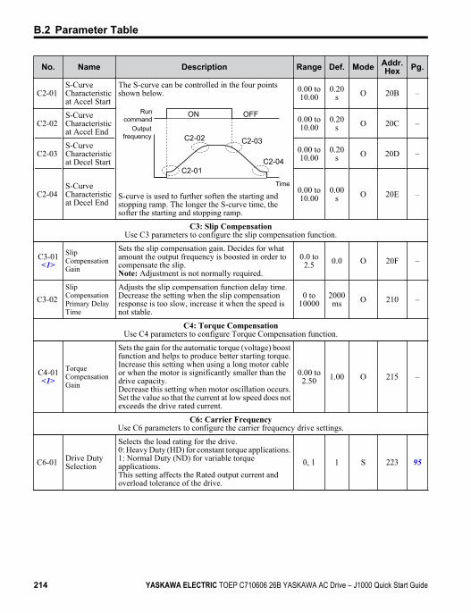
No. Name Description Range Def. Mode Addr.Hex Pg.
C2-01 S-CurveCharacteristicat Accel Start
The S-curve can be controlled in the four pointsshown below.
Run command
Output frequency
Time
C2-01C2-04
C2-02 C2-03
ON OFF
S-curve is used to further soften the starting andstopping ramp. The longer the S-curve time, thesofter the starting and stopping ramp.
0.00 to10.00
0.20s O 20B –
C2-02 S-CurveCharacteristicat Accel End
0.00 to10.00
0.20s O 20C –
C2-03 S-CurveCharacteristicat Decel Start
0.00 to10.00
0.20s O 20D –
C2-04 S-CurveCharacteristicat Decel End
0.00 to10.00
0.00s O 20E –
C3: Slip CompensationUse C3 parameters to configure the slip compensation function.
C3-01<1>
SlipCompensationGain
Sets the slip compensation gain. Decides for whatamount the output frequency is boosted in order tocompensate the slip.Note: Adjustment is not normally required.
0.0 to2.5 0.0 O 20F –
C3-02 SlipCompensationPrimary DelayTime
Adjusts the slip compensation function delay time.Decrease the setting when the slip compensationresponse is too slow, increase it when the speed isnot stable.
0 to10000
2000ms O 210 –
C4: Torque CompensationUse C4 parameters to configure Torque Compensation function.
C4-01<1>
TorqueCompensationGain
Sets the gain for the automatic torque (voltage) boostfunction and helps to produce better starting torque.Increase this setting when using a long motor cableor when the motor is significantly smaller than thedrive capacity.Decrease this setting when motor oscillation occurs.Set the value so that the current at low speed does notexceeds the drive rated current.
0.00 to2.50 1.00 O 215 –
C6: Carrier FrequencyUse C6 parameters to configure the carrier frequency drive settings.
C6-01 Drive DutySelection
Selects the load rating for the drive.0: Heavy Duty (HD) for constant torque applications.1: Normal Duty (ND) for variable torqueapplications.This setting affects the Rated output current andoverload tolerance of the drive.
0, 1 1 S 223 95
B.2 Parameter Table
214 YASKAWA ELECTRIC TOEP C710606 26B YASKAWA AC Drive – J1000 Quick Start Guide
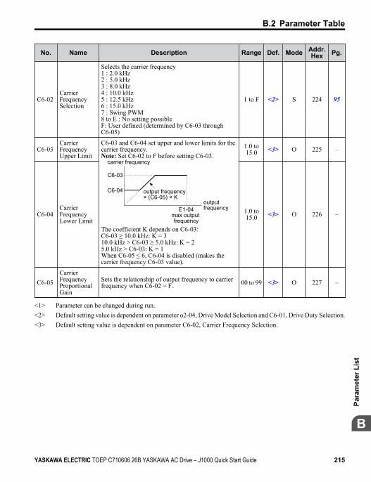
No. Name Description Range Def. Mode Addr.Hex Pg.
C6-02 CarrierFrequencySelection
Selects the carrier frequency1 : 2.0 kHz2 : 5.0 kHz3 : 8.0 kHz4 : 10.0 kHz5 : 12.5 kHz6 : 15.0 kHz7 : Swing PWM8 to E : No setting possibleF: User defined (determined by C6-03 throughC6-05)
1 to F <2> S 224 95
C6-03 CarrierFrequencyUpper Limit
C6-03 and C6-04 set upper and lower limits for thecarrier frequency.Note: Set C6-02 to F before setting C6-03.
carrier frequency
E1-04max output frequency
output frequency× (C6-05) × K
output frequency
C6-03
C6-04
The coefficient K depends on C6-03:C6-03 ≥ 10.0 kHz: K = 310.0 kHz > C6-03 ≥ 5.0 kHz: K = 25.0 kHz > C6-03: K = 1When C6-05 ≤ 6, C6-04 is disabled (makes thecarrier frequency C6-03 value).
1.0 to15.0 <3> O 225 –
C6-04 CarrierFrequencyLower Limit
1.0 to15.0 <3> O 226 –
C6-05 CarrierFrequencyProportionalGain
Sets the relationship of output frequency to carrierfrequency when C6-02 = F. 00 to 99 <3> O 227 –
<1> Parameter can be changed during run.<2> Default setting value is dependent on parameter o2-04, Drive Model Selection and C6-01, Drive Duty Selection.<3> Default setting value is dependent on parameter C6-02, Carrier Frequency Selection.
B.2 Parameter Table
YASKAWA ELECTRIC TOEP C710606 26B YASKAWA AC Drive – J1000 Quick Start Guide 215
B
Para
met
er L
ist
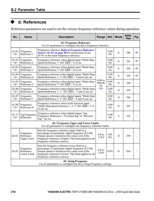
u d: ReferencesReference parameters are used to set the various frequency reference values during operation.
No. Name Description Range Def. Mode Addr.Hex Pg.
d1: Frequency ReferenceUse d1 parameters to configure the drive frequency reference.
d1-01<1>
FrequencyReference 1
Frequency reference. Refer to Frequency Reference Source: b1-01 on page 88 for instructions to used1-01 as the main frequency reference.
0.00 to400.00
Hz<2>
0.00Hz S 280 97
d1-02<1>
FrequencyReference 2
Frequency reference when digital input "Multi-StepSpeed Reference 1" (H1-oo = 3) is on.
0.00Hz S 281 97
d1-03<1>
FrequencyReference 3
Frequency reference when digital input "Multi-StepSpeed Reference 2” (H1-oo = 4) is on.
0.00Hz S 282 97
d1-04<1>
FrequencyReference 4
Frequency reference when digital inputs "Multi-StepSpeed Reference 1, 2" (H1-oo = 3 and 4) are on.
0.00Hz S 283 97
d1-05<1>
FrequencyReference 5
Frequency reference when digital input "Multi-StepSpeed Reference 3" (H1-oo = 5) is on.
0.00Hz O 284 –
d1-06<1>
FrequencyReference 6
Frequency reference when digital inputs "Multi-StepSpeed Reference 1, 3 " (H1-oo = 3 and 5) are on.
0.00Hz O 285 –
d1-07<1>
FrequencyReference 7
Frequency reference when digital inputs "Multi-StepSpeed Reference 2, 3" (H1-oo = 4 and 5) are on.
0.00Hz O 286 –
d1-08<1>
FrequencyReference 8
Frequency reference when multi-function input"Multi-Step speed reference 1, 2, 3" (H1-oo = 3, 4,5) are on.
0.00Hz O 287 –
d1-17<1>
Jog FrequencyReference
Frequency reference when digital inputs "JogFrequency Reference", "Forward Jog" or "ReverseJog." are on.
6.00Hz S 292 –
d2: Frequency Upper and Lower LimitsUse d2 parameters to configure the frequency reference limits.
d2-01 FrequencyReferenceUpper Limit
Sets the frequency reference upper limit as apercentage of maximum output frequency (E1-04).Output speed is limited to this value even if thefrequency reference is higher. This limit applies to allfrequency reference sources.
0.0 to110.0
100.0% O 289 –
d2-02 FrequencyReferenceLower Limit
Sets the frequency reference lower limit as apercentage of maximum output frequency (E1-04).Output speed is limited to this value even if thefrequency reference is lower. This limit applies to allfrequency reference sources.
0.0 to110.0 0.0% O 28A –
d3: Jump FrequencyUse d3 parameters to configure the drive Jump Frequency settings.
B.2 Parameter Table
216 YASKAWA ELECTRIC TOEP C710606 26B YASKAWA AC Drive – J1000 Quick Start Guide
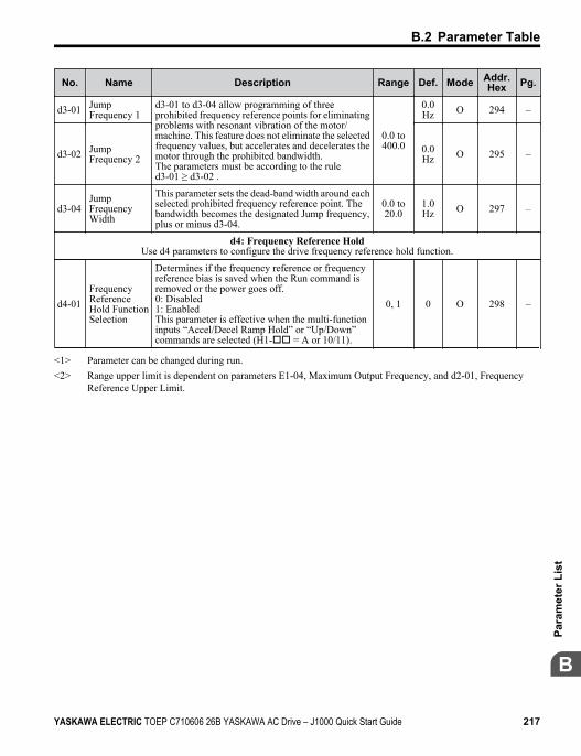
No. Name Description Range Def. Mode Addr.Hex Pg.
d3-01 JumpFrequency 1
d3-01 to d3-04 allow programming of threeprohibited frequency reference points for eliminatingproblems with resonant vibration of the motor/machine. This feature does not eliminate the selectedfrequency values, but accelerates and decelerates themotor through the prohibited bandwidth.The parameters must be according to the ruled3-01 ≥ d3-02 .
0.0 to400.0
0.0Hz O 294 –
d3-02 JumpFrequency 2
0.0Hz O 295 –
d3-04 JumpFrequencyWidth
This parameter sets the dead-band width around eachselected prohibited frequency reference point. Thebandwidth becomes the designated Jump frequency,plus or minus d3-04.
0.0 to20.0
1.0Hz O 297 –
d4: Frequency Reference HoldUse d4 parameters to configure the drive frequency reference hold function.
d4-01 FrequencyReferenceHold FunctionSelection
Determines if the frequency reference or frequencyreference bias is saved when the Run command isremoved or the power goes off.0: Disabled1: EnabledThis parameter is effective when the multi-functioninputs “Accel/Decel Ramp Hold” or “Up/Down”commands are selected (H1-oo = A or 10/11).
0, 1 0 O 298 –
<1> Parameter can be changed during run.<2> Range upper limit is dependent on parameters E1-04, Maximum Output Frequency, and d2-01, Frequency
Reference Upper Limit.
B.2 Parameter Table
YASKAWA ELECTRIC TOEP C710606 26B YASKAWA AC Drive – J1000 Quick Start Guide 217
B
Para
met
er L
ist
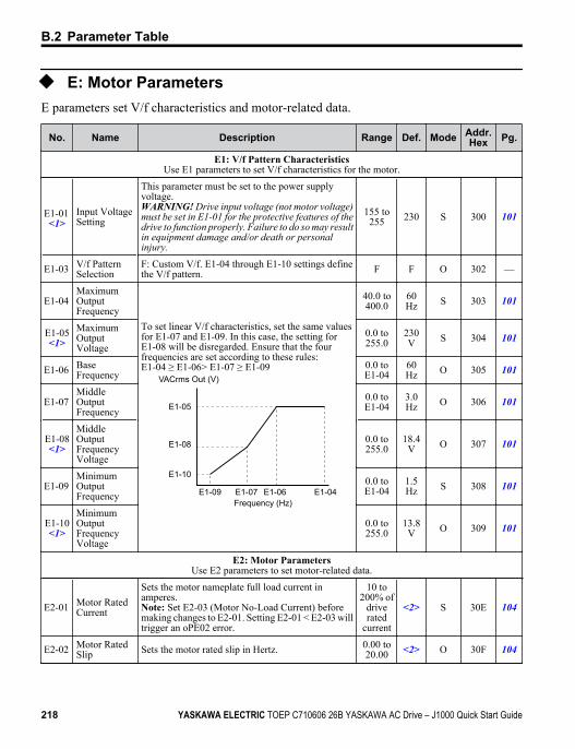
u E: Motor ParametersE parameters set V/f characteristics and motor-related data.
No. Name Description Range Def. Mode Addr.Hex Pg.
E1: V/f Pattern CharacteristicsUse E1 parameters to set V/f characteristics for the motor.
E1-01 <1>
Input VoltageSetting
This parameter must be set to the power supplyvoltage.WARNING! Drive input voltage (not motor voltage)must be set in E1-01 for the protective features of thedrive to function properly. Failure to do so may resultin equipment damage and/or death or personalinjury.
155 to255 230 S 300 101
E1-03 V/f PatternSelection
F: Custom V/f. E1-04 through E1-10 settings definethe V/f pattern. F F O 302 —
E1-04 MaximumOutputFrequency
To set linear V/f characteristics, set the same valuesfor E1-07 and E1-09. In this case, the setting forE1-08 will be disregarded. Ensure that the fourfrequencies are set according to these rules:E1-04 ≥ E1-06> E1-07 ≥ E1-09
E1-05
E1-08
E1-10
E1-09 E1-07 E1-06 E1-04
VACrms Out (V)
Frequency (Hz)
40.0 to400.0
60Hz S 303 101
E1-05<1>
MaximumOutputVoltage
0.0 to255.0
230V S 304 101
E1-06 BaseFrequency
0.0 toE1-04
60Hz O 305 101
E1-07 MiddleOutputFrequency
0.0 toE1-04
3.0Hz O 306 101
E1-08<1>
MiddleOutputFrequencyVoltage
0.0 to255.0
18.4V O 307 101
E1-09 MinimumOutputFrequency
0.0 toE1-04
1.5Hz S 308 101
E1-10<1>
MinimumOutputFrequencyVoltage
0.0 to255.0
13.8V O 309 101
E2: Motor ParametersUse E2 parameters to set motor-related data.
E2-01 Motor RatedCurrent
Sets the motor nameplate full load current inamperes.Note: Set E2-03 (Motor No-Load Current) beforemaking changes to E2-01. Setting E2-01 < E2-03 willtrigger an oPE02 error.
10 to200% of
driverated
current
<2> S 30E 104
E2-02 Motor RatedSlip Sets the motor rated slip in Hertz. 0.00 to
20.00 <2> O 30F 104
B.2 Parameter Table
218 YASKAWA ELECTRIC TOEP C710606 26B YASKAWA AC Drive – J1000 Quick Start Guide
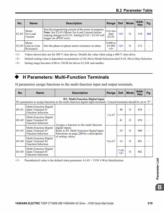
No. Name Description Range Def. Mode Addr.Hex Pg.
E2-03 MotorNo-LoadCurrent
Sets the magnetizing current of the motor in amperes.Note: Set E2-03 (Motor No-Load Current) beforemaking changes to E2-01. Setting E2-01 < E2-03 willtrigger an oPE02 error.
0 to lessthan
E2-01<2> O 310 104
E2-05MotorLine-to-LineResistance
Sets the phase-to-phase motor resistance in ohms.0.000 to65.000
<3><2> O 312 –
<1> Values shown here are for 200 V class drives. Double the value when using a 400 V class drive.<2> Default setting value is dependent on parameter o2-04, Drive Model Selection and C6-01, Drive Duty Selection.<3> Setting range becomes 0.00 to 130.00 for drives 0.2 kW and smaller.
u H Parameters: Multi-Function TerminalsH parameters assign functions to the multi-function input and output terminals.
No. Name Description Range Def. Mode Addr.Hex Pg.
H1: Multi-Function Digital InputH1 parameters to assign functions to the multi-function digital input terminals. Unused terminals should be set to "F".
H1-01 Multi-Function DigitalInput Terminal S1Function Selection
Assigns a function to the multi-functiondigital inputs.Refer to H1 Multi-Function Digital InputSelections on page 220 for a descriptionof setting values.
1 to 67
40 O 438 –
H1-02 Multi-Function DigitalInput Terminal S2Function Selection
41 O 439 –
H1-03 Multi-Function DigitalInput Terminal S3Function Selection
0 to 67
24 O 400 –
H1-04 Multi-Function DigitalInput Terminal S4Function Selection
14 O 401 –
H1-05 Multi-Function DigitalInput Terminal S5Function Selection
3 (0)<1> O 402 –
<1> Parenthetical value is the default when parameter A1-03 = 3330 3-Wire Initialization.
B.2 Parameter Table
YASKAWA ELECTRIC TOEP C710606 26B YASKAWA AC Drive – J1000 Quick Start Guide 219
B
Para
met
er L
ist
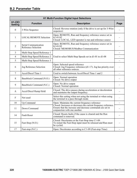
H1 Multi-Function Digital Input SelectionsH1-ooSetting Function Description Page
0 3-Wire Sequence Closed: Reverse rotation (only if the drive is set up for 3-Wiresequence) –
1 LOCAL/REMOTE Selection Open: REMOTE, Run and frequency reference source set inb1-01/02Closed: LOCAL, LED operator is run and reference source
–
2 Serial CommunicationReference Selection
Open: REMOTE, Run and frequency reference source set inb1-01/02Closed: MEMOBUS/Modbus Communication
–
3 Multi-Step Speed Reference 1 Used to select Multi-Step Speeds set in d1-01 to d1-08
–
4 Multi-Step Speed Reference 2 –
5 Multi-Step Speed Reference 3 –
6 Jog Reference Selection Open: Selected speed referenceClosed: Jog Frequency reference (d1-17). Jog has priority overall other reference sources.
–
7 Accel/Decel Time 1 Used to switch between Accel/Decel Time 1 and 2 –
8 Baseblock Command (N.O.) Open: Normal operationClosed: No drive output –
9 Baseblock Command (N.C.) Open: No drive outputClosed: Normal operation –
A Accel/Decel Ramp Hold Closed: The drive pauses during acceleration or decelerationand maintains the output frequency. –
F Not used Select this setting when not using the terminal or when usingthe terminal in a pass-through mode. –
10 Up Command Open: Maintains the current frequency referenceClosed: Increases or decreases the current frequency reference.Ensure that the increase and decrease commands are set inconjunction with one another.
–
11 Down Command –
14 Fault Reset Closed: Resets faults if the cause is cleared and the Runcommand is removed. –
15 Fast-Stop (N.O.) Closed: Decelerates at the Fast-Stop time C1-09.To restart the Fast-Stop input must be released and Run mustbe cycled.
–
17 Fast-stop (N.C.) Open: Decelerates according to C1-09 (Fast-stop Time) –
B.2 Parameter Table
220 YASKAWA ELECTRIC TOEP C710606 26B YASKAWA AC Drive – J1000 Quick Start Guide
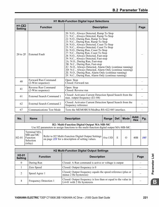
H1 Multi-Function Digital Input SelectionsH1-ooSetting Function Description Page
20 to 2F External Fault
20: N.O., Always Detected, Ramp To Stop21: N.C., Always Detected, Ramp To Stop22: N.O., During Run, Ramp To Stop23: N.C., During Run, Ramp To Stop24: N.O., Always Detected, Coast To Stop25: N.C., Always Detected, Coast To Stop26: N.O., During Run, Coast To Stop27: N.C., During Run, Coast To Stop28: N.O., Always Detected, Fast-stop29: N.C., Always Detected, Fast-stop2A: N.O., During Run, Fast-stop2B: N.C., During Run, Fast-stop2C: N.O., Always Detected, Alarm Only (continue running)2D: N.C., Always Detected, Alarm Only (continue running)2E: N.O., During Run, Alarm Only (continue running)2F: N.C., During Run, Alarm Only (continue running)
–
40 Forward Run Command(2-Wire sequence)
Open: StopClosed: Forward run –
41 Reverse Run Command(2-Wire sequence)
Open: StopClosed: Reverse run –
61 External Search Command 1 Closed: Activates Current Detection Speed Search from themax. output frequency (E1-04) –
62 External Search Command 2 Closed: Activates Current Detection Speed Search from thefrequency reference –
67 Communications Test Mode Tests the MEMOBUS/Modbus RS-422/485 interface. –
No. Name Description Range Def. Mode Addr.Hex Pg.
H2: Multi-Function Digital Output MA-MB-MCUse H2 parameters to assign functions to the multi-function digital output MA-MB-MC.
H2-01
Terminal MA,MB and MCFunctionSelection(relay)
Refer to H2 Multi-Function Digital Output Settingson page 221 for a description of setting values. 0 to 13D E O 40B 105
H2 Multi-Function Digital Output Settings H2-01
Setting Function Description Page
0 During Run Closed: A Run command is active or voltage is output –
1 Zero Speed Closed: Output frequency is 0 –
2 Speed Agree 1 Closed: Output frequency equals the speed reference (plus orminus 2 Hz hysteresis) –
4 Frequency Detection 1 Closed: Output frequency is less than or equal to the value inL4-01 with 2 Hz hysteresis –
B.2 Parameter Table
YASKAWA ELECTRIC TOEP C710606 26B YASKAWA AC Drive – J1000 Quick Start Guide 221
B
Para
met
er L
ist
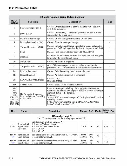
H2 Multi-Function Digital Output Settings H2-01
Setting Function Description Page
5 Frequency Detection 2 Closed: Output frequency is greater than the value in L4-01with 2 Hz hysteresis –
6 Drive Ready Closed: Drive Ready. The drive is powered up, not in a faultstate, and in the Drive mode –
7 DC Bus Undervoltage Closed: DC bus voltage is below the Uv trip level –
8 During Baseblock (N.O.) Closed: There is no output voltage –
B Torque Detection 1 (N.O.) Closed: Output current/torque exceeds the torque value set inparameter L6-02 for longer than the time set in parameter L6-03 –
E Fault Closed: Fault occurred (other than CPF00 and CPF01) –
F Not used Set this value when the terminal is not used, or when using theterminal in the pass-through mode –
10 Minor Fault Closed: An alarm is triggered –
17 Torque Detection 1 (N.C.) Open: When the output current exceeds the value set inparameter L6-02 for more time than is set in parameter L6-03 –
1A Reverse Direction Closed: Drive is running in the reverse direction –
1E Restart Enabled Closed: An automatic restart is performed –
3C LOCAL/REMOTE Status Closed: LOCALOpen: REMOTE –
3D Speed Search Closed: Speed search is being executed –
100 to102;
104 to108;
10B, 10E,110, 117,11A, 11E,13C, 13D
H2 Parameter FunctionsReversed Output Switchingof 0 to 13D
Reverse the output switching of the multi-function outputfunctions. Set the last two digits of 1oo to reverse the outputsignal of that specific functionExamples:Setting “108” reverses the output of “During baseblock”, whichis setting value 08Setting “13C” reverses the output of “LOCAL/REMOTEStatus”, which is setting “3C”
–
No. Name Description Range Def. Mode Addr.Hex Pg.
H3: Analog Input A1Use H3 parameters to set the analog input terminal A1.
H3-01 Terminal A1Signal LevelSelection
Sets the input level for terminal A1.0: 0 to +10 V (lower limit)1: 0 to +10 V (no lower limit)2: 4 to 20 mA3: 0 to 20 mA
0 to 3 0 O 410 –
H3-03<1>
Terminal A1Gain Setting
Sets the level of the input value when 10 V (20 mA)is input at terminal A1.
-999.9to 999.9
100.0% O 411 –
H3-04<1>
Terminal A1Bias Setting
Sets the level of the input value when 0 V (0 or 4 mA)is input at terminal A1.
-999.9to 999.9
0.0% O 412 –
B.2 Parameter Table
222 YASKAWA ELECTRIC TOEP C710606 26B YASKAWA AC Drive – J1000 Quick Start Guide
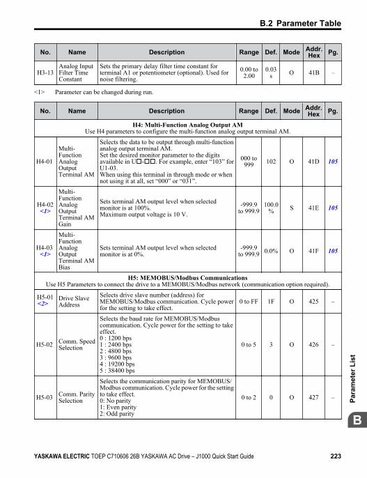
No. Name Description Range Def. Mode Addr.Hex Pg.
H3-13Analog InputFilter TimeConstant
Sets the primary delay filter time constant forterminal A1 or potentiometer (optional). Used fornoise filtering.
0.00 to2.00
0.03s O 41B –
<1> Parameter can be changed during run.
No. Name Description Range Def. Mode Addr.Hex Pg.
H4: Multi-Function Analog Output AMUse H4 parameters to configure the multi-function analog output terminal AM.
H4-01
Multi-FunctionAnalogOutputTerminal AM
Selects the data to be output through multi-functionanalog output terminal AM.Set the desired monitor parameter to the digitsavailable in Uo-oo. For example, enter “103” forU1-03.When using this terminal in through mode or whennot using it at all, set “000” or “031”.
000 to999 102 O 41D 105
H4-02<1>
Multi-FunctionAnalogOutputTerminal AMGain
Sets terminal AM output level when selectedmonitor is at 100%.Maximum output voltage is 10 V.
-999.9to 999.9
100.0% S 41E 105
H4-03 <1>
Multi-FunctionAnalogOutputTerminal AMBias
Sets terminal AM output level when selectedmonitor is at 0%.
-999.9to 999.9 0.0% O 41F 105
H5: MEMOBUS/Modbus CommunicationsUse H5 Parameters to connect the drive to a MEMOBUS/Modbus network (communication option required).
H5-01<2>
Drive SlaveAddress
Selects drive slave number (address) forMEMOBUS/Modbus communication. Cycle powerfor the setting to take effect.
0 to FF 1F O 425 –
H5-02 Comm. SpeedSelection
Selects the baud rate for MEMOBUS/Modbuscommunication. Cycle power for the setting to takeeffect.0 : 1200 bps1 : 2400 bps2 : 4800 bps3 : 9600 bps4 : 19200 bps5 : 38400 bps
0 to 5 3 O 426 –
H5-03 Comm. ParitySelection
Selects the communication parity for MEMOBUS/Modbus communication. Cycle power for the settingto take effect.0: No parity1: Even parity2: Odd parity
0 to 2 0 O 427 –
B.2 Parameter Table
YASKAWA ELECTRIC TOEP C710606 26B YASKAWA AC Drive – J1000 Quick Start Guide 223
B
Para
met
er L
ist
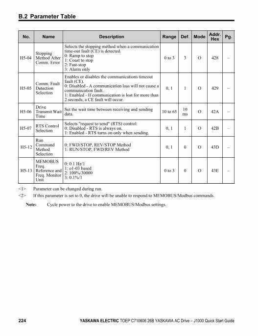
No. Name Description Range Def. Mode Addr.Hex Pg.
H5-04 StoppingMethod AfterComm. Error
Selects the stopping method when a communicationtime-out fault (CE) is detected.0: Ramp to stop1: Coast to stop2: Fast-stop3: Alarm only
0 to 3 3 O 428 –
H5-05 Comm. FaultDetectionSelection
Enables or disables the communications timeoutfault (CE).0: Disabled - A communication loss will not cause acommunication fault.1: Enabled - If communication is lost for more than2 seconds, a CE fault will occur.
0, 1 1 O 429 –
H5-06 DriveTransmit WaitTime
Set the wait time between receiving and sendingdata. 10 to 65 10
ms O 42A –
H5-07 RTS ControlSelection
Selects "request to send" (RTS) control:0: Disabled - RTS is always on.1: Enabled - RTS turns on only when sending.
0, 1 1 O 42B –
H5-12RunCommandMethodSelection
0: FWD/STOP, REV/STOP Method1: RUN/STOP, FWD/REV Method 0, 1 0 O 43D –
H5-13
MEMOBUSFreq.Reference andFreq. MonitorUnit
0: 0.1 Hz/11: o1-03 based2: 100%/300003: 0.1%/1
0 to 3 0 O 43E –
<1> Parameter can be changed during run.<2> If this parameter is set to 0, the drive will be unable to respond to MEMOBUS/Modbus commands.
Note: Cycle power to the drive to enable MEMOBUS/Modbus settings.
B.2 Parameter Table
224 YASKAWA ELECTRIC TOEP C710606 26B YASKAWA AC Drive – J1000 Quick Start Guide
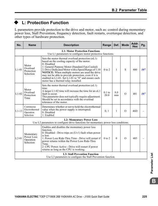
u L: Protection FunctionL parameters provide protection to the drive and motor, such as: control during momentarypower loss, Stall Prevention, frequency detection, fault restarts, overtorque detection, andother types of hardware protection.
No. Name Description Range Def. Mode Addr.Hex Pg.
L1: Motor Protection FunctionsUse L1 parameters to configure motor protective functions.
L1-01 MotorOverloadProtectionSelection
Sets the motor thermal overload protection (oL1)based on the cooling capacity of the motor.0: Disabled1: General Purpose Motor (Standard Fan-Cooled)2: Drive Dedicated Motor with a Speed Range of 1:10NOTICE: When multiple motors are used the drivemay not be able to provide protection, even if it isenabled in L1-01. Set L1-01 to “0” and ensure eachmotor has a thermal relay installed.
0 to 2 1 S 480 107
L1-02 MotorOverloadProtectionTime
Sets the motor thermal overload protection (oL1)time.A larger L1-02 time will increase the time for an oL1fault to occur.This parameter does not typically require adjustment.Should be set in accordance with the overloadtolerance of the motor.
0.1 to20.0
8.0min O 481 107
L1-13 ContinuousElectrothermalOperationSelection
Determines whether or not to hold the electrothermalvalue when the power supply is interrupted.0: Disabled1: Enabled
0, 1 1 O 46D –
L2: Momentary Power LossUse L2 parameters to configure drive functions for momentary power loss conditions.
L2-01 MomentaryPower LossOperationSelection
Enables and disables the momentary power lossfunction.0: Disabled - Drive trips on (Uv1) fault when poweris lost.1: Power Loss Ride-Thru Time - Drive will restart ifpower returns within the Power Loss Ride-ThruTime.2: CPU Power Active - Drive will restart if powerreturns as long as the CPU is working.
0 to 2 0 O 485 –
L3: Stall Prevention FunctionUse L3 parameters to configure the Stall Prevention function.
B.2 Parameter Table
YASKAWA ELECTRIC TOEP C710606 26B YASKAWA AC Drive – J1000 Quick Start Guide 225
B
Para
met
er L
ist
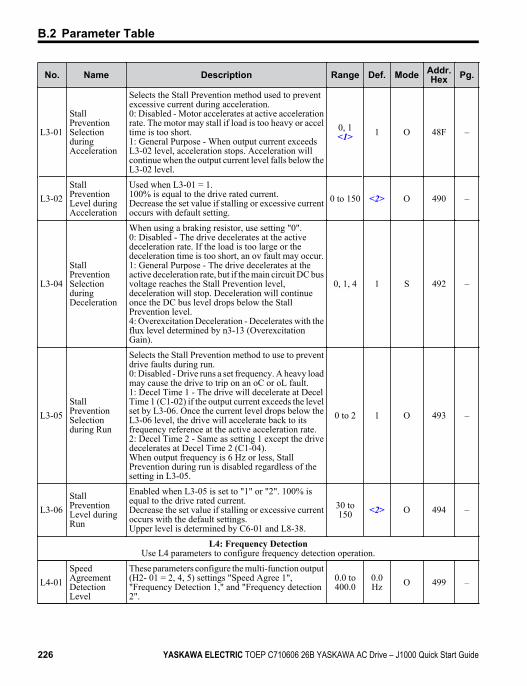
No. Name Description Range Def. Mode Addr.Hex Pg.
L3-01
StallPreventionSelectionduringAcceleration
Selects the Stall Prevention method used to preventexcessive current during acceleration.0: Disabled - Motor accelerates at active accelerationrate. The motor may stall if load is too heavy or acceltime is too short.1: General Purpose - When output current exceedsL3-02 level, acceleration stops. Acceleration willcontinue when the output current level falls below theL3-02 level.
0, 1<1> 1 O 48F –
L3-02 StallPreventionLevel duringAcceleration
Used when L3-01 = 1.100% is equal to the drive rated current.Decrease the set value if stalling or excessive currentoccurs with default setting.
0 to 150 <2> O 490 –
L3-04
StallPreventionSelectionduringDeceleration
When using a braking resistor, use setting "0".0: Disabled - The drive decelerates at the activedeceleration rate. If the load is too large or thedeceleration time is too short, an ov fault may occur.1: General Purpose - The drive decelerates at theactive deceleration rate, but if the main circuit DC busvoltage reaches the Stall Prevention level,deceleration will stop. Deceleration will continueonce the DC bus level drops below the StallPrevention level.4: Overexcitation Deceleration - Decelerates with theflux level determined by n3-13 (OverexcitationGain).
0, 1, 4 1 S 492 –
L3-05 StallPreventionSelectionduring Run
Selects the Stall Prevention method to use to preventdrive faults during run.0: Disabled - Drive runs a set frequency. A heavy loadmay cause the drive to trip on an oC or oL fault.1: Decel Time 1 - The drive will decelerate at DecelTime 1 (C1-02) if the output current exceeds the levelset by L3-06. Once the current level drops below theL3-06 level, the drive will accelerate back to itsfrequency reference at the active acceleration rate.2: Decel Time 2 - Same as setting 1 except the drivedecelerates at Decel Time 2 (C1-04).When output frequency is 6 Hz or less, StallPrevention during run is disabled regardless of thesetting in L3-05.
0 to 2 1 O 493 –
L3-06 StallPreventionLevel duringRun
Enabled when L3-05 is set to "1" or "2". 100% isequal to the drive rated current.Decrease the set value if stalling or excessive currentoccurs with the default settings.Upper level is determined by C6-01 and L8-38.
30 to150 <2> O 494 –
L4: Frequency DetectionUse L4 parameters to configure frequency detection operation.
L4-01 SpeedAgreementDetectionLevel
These parameters configure the multi-function output(H2- 01 = 2, 4, 5) settings "Speed Agree 1","Frequency Detection 1," and "Frequency detection2".
0.0 to400.0
0.0Hz O 499 –
B.2 Parameter Table
226 YASKAWA ELECTRIC TOEP C710606 26B YASKAWA AC Drive – J1000 Quick Start Guide
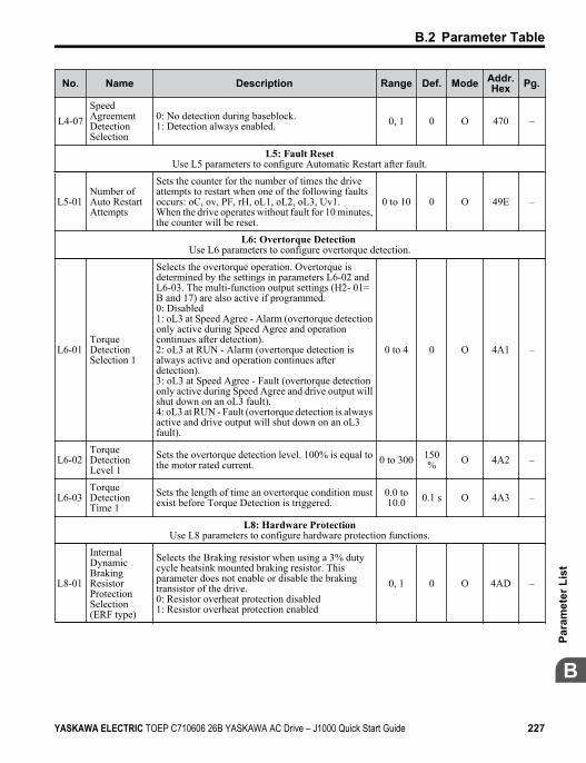
No. Name Description Range Def. Mode Addr.Hex Pg.
L4-07SpeedAgreementDetectionSelection
0: No detection during baseblock.1: Detection always enabled. 0, 1 0 O 470 –
L5: Fault ResetUse L5 parameters to configure Automatic Restart after fault.
L5-01 Number ofAuto RestartAttempts
Sets the counter for the number of times the driveattempts to restart when one of the following faultsoccurs: oC, ov, PF, rH, oL1, oL2, oL3, Uv1.When the drive operates without fault for 10 minutes,the counter will be reset.
0 to 10 0 O 49E –
L6: Overtorque Detection Use L6 parameters to configure overtorque detection.
L6-01 TorqueDetectionSelection 1
Selects the overtorque operation. Overtorque isdetermined by the settings in parameters L6-02 andL6-03. The multi-function output settings (H2- 01=B and 17) are also active if programmed.0: Disabled1: oL3 at Speed Agree - Alarm (overtorque detectiononly active during Speed Agree and operationcontinues after detection).2: oL3 at RUN - Alarm (overtorque detection isalways active and operation continues afterdetection).3: oL3 at Speed Agree - Fault (overtorque detectiononly active during Speed Agree and drive output willshut down on an oL3 fault).4: oL3 at RUN - Fault (overtorque detection is alwaysactive and drive output will shut down on an oL3fault).
0 to 4 0 O 4A1 –
L6-02 TorqueDetectionLevel 1
Sets the overtorque detection level. 100% is equal tothe motor rated current. 0 to 300 150
% O 4A2 –
L6-03 TorqueDetectionTime 1
Sets the length of time an overtorque condition mustexist before Torque Detection is triggered.
0.0 to10.0 0.1 s O 4A3 –
L8: Hardware ProtectionUse L8 parameters to configure hardware protection functions.
L8-01
InternalDynamicBrakingResistorProtectionSelection(ERF type)
Selects the Braking resistor when using a 3% dutycycle heatsink mounted braking resistor. Thisparameter does not enable or disable the brakingtransistor of the drive.0: Resistor overheat protection disabled1: Resistor overheat protection enabled
0, 1 0 O 4AD –
B.2 Parameter Table
YASKAWA ELECTRIC TOEP C710606 26B YASKAWA AC Drive – J1000 Quick Start Guide 227
B
Para
met
er L
ist
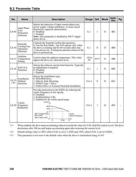
No. Name Description Range Def. Mode Addr.Hex Pg.
L8-05 Input PhaseLossProtectionSelection
Selects the detection of input current phase loss,power supply voltage imbalance, or main circuitelectrolytic capacitor deterioration.0: Disabled1: EnabledNote: This parameter is disabled in 200 V single-phase drives.
0, 1 1 O 4B1 –
L8-10 HeatsinkCooling FanOperationSelection
Controls the heatsink cooling fan operation.0: Fan On-Run Mode - Fan will operate only whenthe drive is running and for 60 seconds after stop.1: Fan always on - Cooling fan operates whenever thedrive is powered up.
0, 1 0 O 4B6 –
L8-12 AmbientTemperatureSetting
Used to input the ambient temperature. This valueadjusts the drive oL2 detection level.
-10 to50 30 °C O 4B8 –
L8-18 Soft CLASelection
Selects the software current limit function. Typicallyno adjustment is required.0: Disabled1: Enabled
0, 1 1 O 4BE –
L8-35<3>
InstallationMethodSelection
Selects the installation type:0: IP20/IP00 Drive1: Side-by-Side Mounting2: NEMA Type 1 Drive3: Finless Drive or External Heatsink Installation
0 to 3 0 O 4EC –
L8-38 CarrierFrequencyReduction
Provides protection to the IGBTs by reducing thecarrier frequency at low speeds.0: Disabled1: Enabled below 6 Hz2: Enabled for the whole speed range
Current
C6-02Carrier Frequency
NDHD
20
200 V Single Phase80% of HD
10 (8) 15400 V: 60% of HD
0 to 2 1 O 4EF –
<1> When enabled, the drive stops accelerating when it exceeds the value of L3-02, Stall Prevention Level. The drivedecelerates after 100 ms and begins accelerating again after restoring the current level.
<2> Default setting value is 120% when C6-01 is set to 1 (ND) and 150% when C6-01 is set to 0 (HD).<3> This parameter is not reset to the default value when the drive is reinitialized using A1-03.
B.2 Parameter Table
228 YASKAWA ELECTRIC TOEP C710606 26B YASKAWA AC Drive – J1000 Quick Start Guide
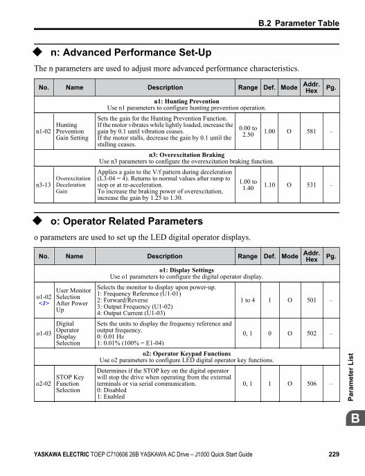
u n: Advanced Performance Set-UpThe n parameters are used to adjust more advanced performance characteristics.
No. Name Description Range Def. Mode Addr.Hex Pg.
n1: Hunting PreventionUse n1 parameters to configure hunting prevention operation.
n1-02 HuntingPreventionGain Setting
Sets the gain for the Hunting Prevention Function.If the motor vibrates while lightly loaded, increase thegain by 0.1 until vibration ceases.If the motor stalls, decrease the gain by 0.1 until thestalling ceases.
0.00 to2.50 1.00 O 581 –
n3: Overexcitation BrakingUse n3 parameters to configure the overexcitation braking function.
n3-13 OverexcitationDecelerationGain
Applies a gain to the V/f pattern during deceleration(L3-04 = 4). Returns to normal values after ramp tostop or at re-acceleration.To increase the braking power of overexcitation,increase the gain by 1.25 to 1.30.
1.00 to1.40 1.10 O 531 –
u o: Operator Related Parameterso parameters are used to set up the LED digital operator displays.
No. Name Description Range Def. Mode Addr.Hex Pg.
o1: Display SettingsUse o1 parameters to configure the digital operator display.
o1-02<1>
User MonitorSelectionAfter PowerUp
Selects the monitor to display upon power-up.1: Frequency Reference (U1-01)2: Forward/Reverse3: Output Frequency (U1-02)4: Output Current (U1-03)
1 to 4 1 O 501 –
o1-03DigitalOperatorDisplaySelection
Sets the units to display the frequency reference andoutput frequency.0: 0.01 Hz1: 0.01% (100% = E1-04)
0, 1 0 O 502 –
o2: Operator Keypad FunctionsUse o2 parameters to configure LED digital operator key functions.
o2-02 STOP KeyFunctionSelection
Determines if the STOP key on the digital operatorwill stop the drive when operating from the externalterminals or via serial communication.0: Disabled1: Enabled
0, 1 1 O 506 –
B.2 Parameter Table
YASKAWA ELECTRIC TOEP C710606 26B YASKAWA AC Drive – J1000 Quick Start Guide 229
B
Para
met
er L
ist
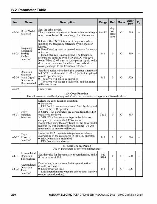
No. Name Description Range Def. Mode Addr.Hex Pg.
o2-04 Drive ModelSelection
Sets the drive model.This parameter only needs to be set when installing anew control board. Do not change for other reason.
0 to FFdep.on
drivespec.
O 508 –
o2-05
FrequencyReferenceSettingMethodSelection
Selects if the ENTER key must be pressed wheninputting the frequency reference by the operatorkeypad.0: Data/Enter key must be pressed to enter a frequencyreference.1: Data/Enter key is not required. The frequencyreference is adjusted by the UP and DOWN keys.Note: When o2-05 is set to 1, the power supply to thedrive must remain on for at least 5 seconds aftermaking changes to the frequency reference.
0, 1 0 O 509 –
o2-06
OperationSelectionwhen DigitalOperator isDisconnected
Sets drive action when the digital operator is removedin LOCAL mode or with b1-02 = 0 (valid for optionalremote operator only).0: The drive will continue operation1: The drive will trigger a fault (oPr) and the motorwill coast to stop
0, 1 0 O 50A –
o2-09 – Factory use. – – – – –
o3: Copy FunctionUse o3 parameters to Read, Copy and Verify the parameter settings to and from the drive.
o3-01CopyFunctionSelection
Selects the copy function operation.0: No action1: READ - All parameters are read from the drive andstored in the LED operator.2: COPY - All parameters are copied from the LEDoperator to the drive.3: VERIFY - Parameter settings in the drive arecompared to those in the LED operator.Note: When using the copy function, the drive modelnumber (o2-04) and the software number (U1-26)must match or an error will occur.
0 to 3 0 O 515 –
o3-02CopyAllowedSelection
Locks the READ operation to prevent accidentaloverwriting of the data stored in the LED operator.0: READ operation prohibited1: READ operation allowed
0, 1 0 O 516 –
o4: Maintenance PeriodUse o4 parameters to perform maintenance.
o4-01 AccumulatedOperationTime Setting
Sets the value for the cumulative operation time of thedrive in units of 10 h.
0 to9999 0 O 50B –
o4-02 AccumulatedOperationTimeSelection
Determines, how the cumulative operation time(U4-01) is counted.0: Logs power-on time1: Logs operation time when the drive output is active(output operation time).
0, 1 0 O 50C –
B.2 Parameter Table
230 YASKAWA ELECTRIC TOEP C710606 26B YASKAWA AC Drive – J1000 Quick Start Guide
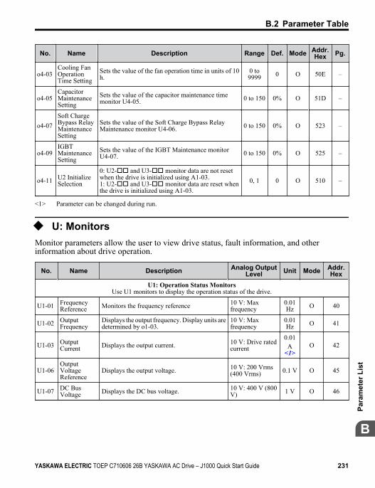
No. Name Description Range Def. Mode Addr.Hex Pg.
o4-03 Cooling FanOperationTime Setting
Sets the value of the fan operation time in units of 10h.
0 to9999 0 O 50E –
o4-05 CapacitorMaintenanceSetting
Sets the value of the capacitor maintenance timemonitor U4-05. 0 to 150 0% O 51D –
o4-07 Soft ChargeBypass RelayMaintenanceSetting
Sets the value of the Soft Charge Bypass RelayMaintenance monitor U4-06. 0 to 150 0% O 523 –
o4-09 IGBTMaintenanceSetting
Sets the value of the IGBT Maintenance monitorU4-07. 0 to 150 0% O 525 –
o4-11 U2 InitializeSelection
0: U2-oo and U3-oo monitor data are not resetwhen the drive is initialized using A1-03.1: U2-oo and U3-oo monitor data are reset whenthe drive is initialized using A1-03.
0, 1 0 O 510 –
<1> Parameter can be changed during run.
u U: MonitorsMonitor parameters allow the user to view drive status, fault information, and otherinformation about drive operation.
No. Name Description Analog OutputLevel Unit Mode Addr.
HexU1: Operation Status Monitors
Use U1 monitors to display the operation status of the drive.
U1-01 FrequencyReference Monitors the frequency reference 10 V: Max
frequency0.01Hz O 40
U1-02 OutputFrequency
Displays the output frequency. Display units aredetermined by o1-03.
10 V: Maxfrequency
0.01Hz O 41
U1-03 OutputCurrent Displays the output current. 10 V: Drive rated
current
0.01A
<1>O 42
U1-06 OutputVoltageReference
Displays the output voltage. 10 V: 200 Vrms(400 Vrms) 0.1 V O 45
U1-07 DC BusVoltage Displays the DC bus voltage. 10 V: 400 V (800
V) 1 V O 46
B.2 Parameter Table
YASKAWA ELECTRIC TOEP C710606 26B YASKAWA AC Drive – J1000 Quick Start Guide 231
B
Para
met
er L
ist
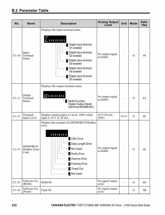
No. Name Description Analog OutputLevel Unit Mode Addr.
Hex
U1-10 InputTerminalStatus
Displays the input terminal status.
Digital input terminal S1 enabledDigital input terminal S2 enabledDigital input terminal S3 enabledDigital input terminal S4 enabledDigital input terminal S5 enabled
No output signalavailable – O 49
U1-11 OutputTerminalStatus
Displays the output terminal status.
Multi-Function Digital Output (fault) (terminal MA/MB-MC)
No output signalavailable – O 4A
U1-13 TerminalInput Level
Displays analog input A1 level: 100% wheninput is 10 V or 20 mA.
10 V/20 mA:100% 0.1% O 4E
U1-19 MEMOBUS/Modbus ErrorCode
Displays the contents of a MEMOBUS/Modbuserror.
CRC Error
Data Length Error
Not Used
Parity Error
Overrun Error
Framing Error
Timed Out
Not Used
No output signalavailable – O 66
U1-25 Software No.(ROM) ROM ID No signal output
avail. – O 4D
U1-26 Software No.(Flash) Flash ID No signal output
avail. – O 5B
B.2 Parameter Table
232 YASKAWA ELECTRIC TOEP C710606 26B YASKAWA AC Drive – J1000 Quick Start Guide
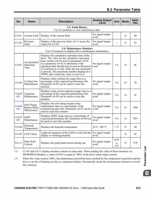
No. Name Description Analog OutputLevel Unit Mode Addr.
HexU2: Fault History
Use U2 monitors to view fault history data.
U2-01 Current Fault Display of the current fault. No signal outputavail. – O 80
U2-02 PreviousFault
Display of the previous fault. o4-11 resets thevalues for U2-02
No signal outputavail. – O 81
U4: Maintenance MonitorsUse U4 monitors to display drive maintenance information.
U4-01 AccumulatedOperationTime
Displays the cumulative operation time of thedrive. The value for the cumulative operationtime counter can be reset in parameter o4-01.Use parameter o4-02 to determine if theoperation time should start as soon as the poweris switched on or only while the run commandis present. The maximum number displayed is99999, after which the value is reset to 0.
No signal outputavail. 1 h O 4C
U4-04 Cooling FanMaintenance
Displays main cooling fan usage time as apercentage of the expected performance life.Parameter o4-03 can be used to reset thismonitor.
No signal outputavail. 1% O 7E
U4-05<2>
CapacitorMaintenance
Displays main circuit capacitor usage time as apercentage of the expected performance life.Parameter o4-05 can be used to reset thismonitor.
No signal outputavail. 1% O 7C
U4-06<2>
Soft ChargeBypass RelayMaintenance
Displays the soft charge bypass relaymaintenance time as a percentage of theestimated product life. Parameter o4-07 can beused to reset this monitor.
No signal outputavail. 1% O 7D6
U4-07<2>
IGBTMaintenance
Displays IGBT usage time as a percentage ofexpected performance life. Parameter o4-09 canbe used to reset this monitor.
No signal outputavail. 1% O 7D7
U4-08 HeatsinkTemperature Displays the heatsink temperature. 10 V: 100 °C 1 °C O 68
U4-09 LED Check Lights all segments of the LED to verify that thedisplay is working properly.
No signal outputavail. – O 3C
U4-13 Peak HoldCurrent Displays the peak hold current during run. No signal output
avail.
0.01A
<1>O 7CF
<1> U1-03 and U4-13 display monitor contents in amp units. When reading the value of these monitors viaMEMOBUS/Modbus, a value of 8192 is equal to 100% of the drive rated output current.
<2> When this value reaches 100%, the maintenance period has been reached for the component in question and thedrive is at risk of faulting out due to component failure. Periodically check the maintenance monitors to avoidthis situation.
B.2 Parameter Table
YASKAWA ELECTRIC TOEP C710606 26B YASKAWA AC Drive – J1000 Quick Start Guide 233
B
Para
met
er L
ist
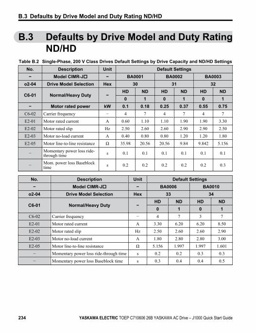
B.3 Defaults by Drive Model and Duty RatingND/HD
Table B.2 Single-Phase, 200 V Class Drives Default Settings by Drive Capacity and ND/HD SettingsNo. Description Unit Default Settings− Model CIMR-Jo − BA0001 BA0002 BA0003
o2-04 Drive Model Selection Hex 30 31 32
C6-01 Normal/Heavy Duty −HD ND HD ND HD ND0 1 0 1 0 1
− Motor rated power kW 0.1 0.18 0.25 0.37 0.55 0.75C6-02 Carrier frequency − 4 7 4 7 4 7
E2-01 Motor rated current A 0.60 1.10 1.10 1.90 1.90 3.30
E2-02 Motor rated slip Hz 2.50 2.60 2.60 2.90 2.90 2.50
E2-03 Motor no-load current A 0.40 0.80 0.80 1.20 1.20 1.80
E2-05 Motor line-to-line resistance Ω 35.98 20.56 20.56 9.84 9.842 5.156
− Momentary power loss ride-through time s 0.1 0.1 0.1 0.1 0.1 0.1
− Mom. power loss Baseblocktime s 0.2 0.2 0.2 0.2 0.2 0.3
No. Description Unit Default Settings− Model CIMR-Jo − BA0006 BA0010
o2-04 Drive Model Selection Hex 33 34
C6-01 Normal/Heavy Duty −HD ND HD ND0 1 0 1
C6-02 Carrier frequency − 4 7 3 7
E2-01 Motor rated current A 3.30 6.20 6.20 8.50
E2-02 Motor rated slip Hz 2.50 2.60 2.60 2.90
E2-03 Motor no-load current A 1.80 2.80 2.80 3.00
E2-05 Motor line-to-line resistance Ω 5.156 1.997 1.997 1.601
− Momentary power loss ride-through time s 0.2 0.2 0.3 0.3
− Momentary power loss Baseblock time s 0.3 0.4 0.4 0.5
B.3 Defaults by Drive Model and Duty Rating ND/HD
234 YASKAWA ELECTRIC TOEP C710606 26B YASKAWA AC Drive – J1000 Quick Start Guide
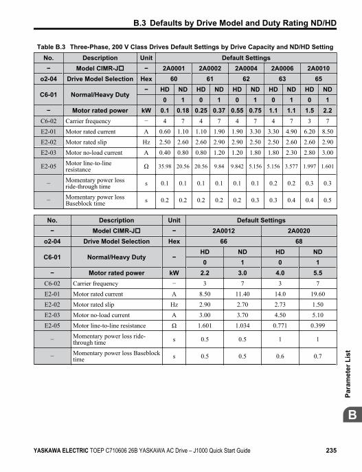
Table B.3 Three-Phase, 200 V Class Drives Default Settings by Drive Capacity and ND/HD SettingNo. Description Unit Default Settings− Model CIMR-Jo − 2A0001 2A0002 2A0004 2A0006 2A0010
o2-04 Drive Model Selection Hex 60 61 62 63 65
C6-01 Normal/Heavy Duty− HD ND HD ND HD ND HD ND HD ND 0 1 0 1 0 1 0 1 0 1
− Motor rated power kW 0.1 0.18 0.25 0.37 0.55 0.75 1.1 1.1 1.5 2.2C6-02 Carrier frequency − 4 7 4 7 4 7 4 7 3 7
E2-01 Motor rated current A 0.60 1.10 1.10 1.90 1.90 3.30 3.30 4.90 6.20 8.50
E2-02 Motor rated slip Hz 2.50 2.60 2.60 2.90 2.90 2.50 2.50 2.60 2.60 2.90
E2-03 Motor no-load current A 0.40 0.80 0.80 1.20 1.20 1.80 1.80 2.30 2.80 3.00
E2-05 Motor line-to-lineresistance Ω 35.98 20.56 20.56 9.84 9.842 5.156 5.156 3.577 1.997 1.601
− Momentary power lossride-through time s 0.1 0.1 0.1 0.1 0.1 0.1 0.2 0.2 0.3 0.3
− Momentary power lossBaseblock time s 0.2 0.2 0.2 0.2 0.2 0.3 0.3 0.4 0.4 0.5
No. Description Unit Default Settings− Model CIMR-Jo − 2A0012 2A0020
o2-04 Drive Model Selection Hex 66 68
C6-01 Normal/Heavy Duty −HD ND HD ND0 1 0 1
− Motor rated power kW 2.2 3.0 4.0 5.5C6-02 Carrier frequency − 3 7 3 7
E2-01 Motor rated current A 8.50 11.40 14.0 19.60
E2-02 Motor rated slip Hz 2.90 2.70 2.73 1.50
E2-03 Motor no-load current A 3.00 3.70 4.50 5.10
E2-05 Motor line-to-line resistance Ω 1.601 1.034 0.771 0.399
− Momentary power loss ride-through time s 0.5 0.5 1 1
− Momentary power loss Baseblocktime s 0.5 0.5 0.6 0.7
B.3 Defaults by Drive Model and Duty Rating ND/HD
YASKAWA ELECTRIC TOEP C710606 26B YASKAWA AC Drive – J1000 Quick Start Guide 235
B
Para
met
er L
ist
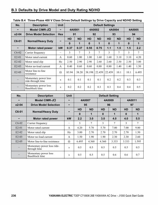
Table B.4 Three-Phase 400 V Class Drives Default Settings by Drive Capacity and ND/HD SettingNo. Description Unit Default Settings− Model CIMR-Jo − 4A0001 4A0002 4A0004 4A0005
o2-04 Drive Model Selection Hex 91 92 93 94
C6-01 Normal/Heavy Duty −HD ND HD ND HD ND HD ND0 1 0 1 0 1 0 1
− Motor rated power kW 0.37 0.37 0.55 0.75 1.1 1.5 1.5 2.2C6-02 Carrier frequency − 3 7 3 7 3 7 3 7
E2-01 Motor rated current A 0.60 1.00 1.00 1.60 1.60 3.10 3.10 4.20
E2-02 Motor rated slip Hz 2.50 2.90 2.90 2.60 2.60 2.50 2.50 3.00
E2-03 Motor no-load current A 0.40 0.60 0.60 0.80 0.80 1.40 1.40 1.50
E2-05 Motor line-to-lineresistance Ω 83.94 38.20 38.198 22.459 22.459 10.1 10.1 6.495
− Momentary power lossride-through time s 0.1 0.1 0.1 0.1 0.2 0.2 0.3 0.3
− Momentary power lossBaseblock time s 0.2 0.2 0.2 0.3 0.3 0.4 0.4 0.5
No. Description Unit Default Setting− Model CIMR-Jo − 4A0007 4A0009 4A0011
o2-04 Drive Model Selection − 95 96 97
C6-01 Normal/Heavy Duty −HD ND HD ND HD ND0 1 0 1 0 1
− Motor rated power kW 2.2 3.0 3.0 4.0 4.0 5.5C6-02 Carrier frequency − 3 7 3 7 3 7
E2-01 Motor rated current A 4.20 5.70 5.70 7.00 7.00 9.80
E2-02 Motor rated slip Hz 3.00 2.70 2.70 2.70 2.70 1.50
E2-03 Motor no-load current A 1.50 1.90 1.90 2.30 2.30 2.60
E2-05 Motor line-to-line resistance Ω 6.495 4.360 4.360 3.333 3.333 1.595
− Momentary power loss ride-through time s 0.5 0.5 0.5 0.5 0.5 0.5
− Momentary power lossBaseblock time s 0.5 0.5 0.5 0.6 0.6 0.7
B.3 Defaults by Drive Model and Duty Rating ND/HD
236 YASKAWA ELECTRIC TOEP C710606 26B YASKAWA AC Drive – J1000 Quick Start Guide

StandardsCompliance
This appendix explains the guidelines and criteria formaintaining CE and UL standards.
C.1 SECTION SAFETY...........................................238C.2 EUROPEAN STANDARDS...............................241C.3 UL STANDARDS.............................................247
Appendix: C
YASKAWA ELECTRIC TOEP C710606 26B YASKAWA AC Drive – J1000 Quick Start Guide 237

C.1 Section Safety
DANGER
Electrical Shock HazardDo not connect or disconnect wiring while the power is on.Failure to comply will result in death or serious injury.
WARNING
Electrical Shock HazardDo not operate equipment with covers removed.Failure to comply could result in death or serious injury.The diagrams in this section may show drives without covers or safety shields to showdetails. Be sure to reinstall covers or shields before operating the drives and run the drivesaccording to the instructions described in this manual.Always ground the motor-side grounding terminal.Improper equipment grounding could result in death or serious injury by contacting themotor case.Do not touch any terminals before the capacitors have fully discharged.Failure to comply could result in death or serious injury.Before wiring terminals, disconnect all power to the equipment. The internal capacitorremains charged even after the power supply is turned off. The charge indicator LED willextinguish when the DC bus voltage is below 50 Vdc. To prevent electric shock, wait atleast one minute after all indicators are off and measure the DC bus voltage level to confirmsafe level.Do not allow unqualified personnel to perform work on the drive.Failure to comply could result in death or serious injury.Installation, maintenance, inspection, and servicing must be performed only by authorizedpersonnel familiar with installation, adjustment and maintenance of AC drives.
C.1 Section Safety
238 YASKAWA ELECTRIC TOEP C710606 26B YASKAWA AC Drive – J1000 Quick Start Guide
WARNINGDo not perform work on the drive while wearing loose clothing, jewelry or without eyeprotection.Failure to comply could result in death or serious injury.Remove all metal objects such as watches and rings, secure loose clothing, and wear eyeprotection before beginning work on the drive.Do not remove covers or touch circuit boards while the power is on.Failure to comply could result in death or serious injury.
Fire HazardTighten all terminal screws to the specified tightening torque.Loose electrical connections could result in death or serious injury by fire due to overheatingof electrical connections.Do not use an improper voltage source.Failure to comply could result in death or serious injury by fire.Verify that the rated voltage of the drive matches the voltage of the incoming power supplybefore applying power.Do not use improper combustible materials.Failure to comply could result in death or serious injury by fire.Attach the drive to metal or other noncombustible material.Install adequate branch circuit protection according to applicable local codes and thismanual.Failure to comply could result in fire and damage to the drive or injury to personnel. Thedevice is suitable for use on a circuit capable of delivering not more than 31,000 RMSsymmetrical amperes, 240 Vac maximum (200 V class) and 480 Vac maximum (400 Vclass) when protected by branch circuit protection devices specified in this manual.
C.1 Section Safety
YASKAWA ELECTRIC TOEP C710606 26B YASKAWA AC Drive – J1000 Quick Start Guide 239C
Stan
dard
s C
ompl
ianc
e
NOTICE
Observe proper electrostatic discharge procedures (ESD) when handling the drive andcircuit boards.Failure to comply may result in ESD damage to the drive circuitry.Never connect or disconnect the motor from the drive while the drive is outputtingvoltage.Improper equipment sequencing could result in damage to the drive.Do not use unshielded cable for control wiring.Failure to comply may cause electrical interference resulting in poor system performance.Use shielded twisted-pair wires and ground the shield to the ground terminal of the drive.Do not allow unqualified personnel to use the product.Failure to comply could result in damage to the drive or braking circuit.Carefully review instruction manual TOBPC72060000 when connecting a braking optionto the drive.Do not modify the drive circuitry.Failure to comply could result in damage to the drive and will void warranty.Yaskawa is not responsible for modification of the product made by the user. This productmust not be modified.Check all the wiring to ensure that all connections are correct after installing the driveand connecting other devices.Failure to comply could result in damage to the drive.
C.1 Section Safety
240 YASKAWA ELECTRIC TOEP C710606 26B YASKAWA AC Drive – J1000 Quick Start Guide
C.2 European Standards
Figure C.1 CE Mark
The CE mark indicates compliance with European safety and environmental regulations andis required for engaging in business and commerce in Europe.European standards include the Machinery Directive for machine manufacturers, the LowVoltage Directive for electronics manufacturers and the EMC guidelines for controlling noise.This drive displays the CE mark based on the EMC guidelines and the Low Voltage Directive.• EMC Guidelines: 2004/108/EC• Low Voltage Directive: 2006/95/EC
u CE Low Voltage Directive ComplianceThis drive has been tested according to IEC61800-5-1:2007, and it fully complies with theLow Voltage Directive.To comply with the Low Voltage Directive, be sure to meet the following conditions whencombining this drive with other devices:
n Area of UseDo not use drives in areas with pollution higher than severity 2 and overvoltage category 3 inaccordance with IEC664.
n Installing Fuses on the Input SideAlways install input fuses that comply with UL standards to prevent the drive from shortcircuits. Refer to Factory Recommended Drive Branch Circuit Protection on page 251 forthe appropriate fuse based on the maximum input of the drive. Refer to Heavy Duty and Normal Duty Ratings on page 198 for information on drive input and output currents.
n GroundingThe drive is designed to be used in T-N (grounded neutral point) networks. If installing thedrive in other types of grounded systems, contact your dealer or Yaskawa for instructions.
C.2 European Standards
YASKAWA ELECTRIC TOEP C710606 26B YASKAWA AC Drive – J1000 Quick Start Guide 241C
Stan
dard
s C
ompl
ianc
e
u EMC Guidelines ComplianceThis drive is tested according to IEC61800-3:2004 and it complies with the EMC guidelines.
n EMC Filter InstallationThe following conditions must be met to ensure continued compliance with guidelines. Refer to EMC Filters on page 245 for EMC filter selection.
Installation MethodVerify the following installation conditions to ensure that other devices and machinery usedin combination with this drive also comply with EMC guidelines.
1. Install an EMC noise filter to the input side specified by Yaskawa for compliance withEuropean standards.
2. Place the drive and EMC noise filter in the same enclosure.3. Use braided shield cable for the drive and motor wiring or run the wiring through a
metal conduit.4. Keep wiring as short as possible. Ground the shield on both the drive side and the
motor side.5. Ground the largest possible surface area of the shield to the metal conduit when using
braided shield cable. Yaskawa recommends using a cable clamp.
C.2 European Standards
242 YASKAWA ELECTRIC TOEP C710606 26B YASKAWA AC Drive – J1000 Quick Start Guide
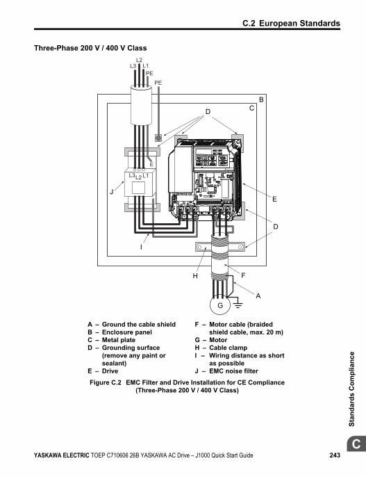
Three-Phase 200 V / 400 V Class
BCD
E
D
F
AG
J
I
H
L3L2 L1
E
L1PE
L3L2
PE
A – Ground the cable shieldB – Enclosure panelC – Metal plateD – Grounding surface
(remove any paint orsealant)
E – Drive
F – Motor cable (braidedshield cable, max. 20 m)
G – MotorH – Cable clampI – Wiring distance as short
as possibleJ – EMC noise filter
Figure C.2 EMC Filter and Drive Installation for CE Compliance(Three-Phase 200 V / 400 V Class)
C.2 European Standards
YASKAWA ELECTRIC TOEP C710606 26B YASKAWA AC Drive – J1000 Quick Start Guide 243C
Stan
dard
s C
ompl
ianc
e
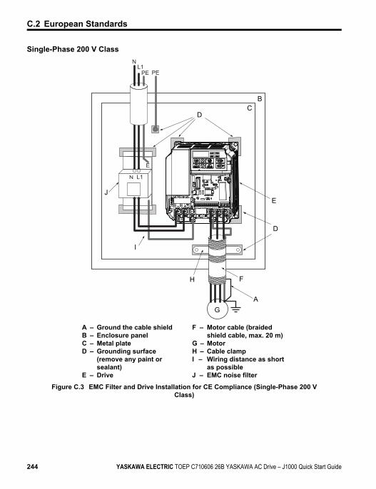
Single-Phase 200 V Class
BC
D
E
D
F
A
H
G
J
I
N L1
E
NL1
PE PE
A – Ground the cable shieldB – Enclosure panelC – Metal plateD – Grounding surface
(remove any paint orsealant)
E – Drive
F – Motor cable (braidedshield cable, max. 20 m)
G – MotorH – Cable clampI – Wiring distance as short
as possibleJ – EMC noise filter
Figure C.3 EMC Filter and Drive Installation for CE Compliance (Single-Phase 200 VClass)
C.2 European Standards
244 YASKAWA ELECTRIC TOEP C710606 26B YASKAWA AC Drive – J1000 Quick Start Guide
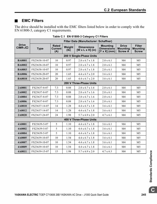
n EMC FiltersThe drive should be installed with the EMC filters listed below in order to comply with theEN 61800-3, category C1 requirements.
Table C.1 EN 61800-3 Category C1 Filters
DriveCIMR-Jo
Filter Data (Manufacturer: Schaffner)
TypeRated
Current(A)
Weight(lb)
Dimensions[W x L x H] (in)
MountingDimensions[Y x X] (mm)
DriveMountingScrew A
FilterMounting
Screw200 V Single-Phase Units
BA0001 FS23638-10-07 10 0.97 2.8 x 6.7 x 1.8 2.0 x 6.1 M4 M5
BA0002 FS23638-10-07 10 0.97 2.8 x 6.7 x 1.8 2.0 x 6.1 M4 M5
BA0003 FS23638-10-07 10 0.97 2.8 x 6.7 x 1.8 2.0 x 6.1 M4 M5
BA0006 FS23638-20-07 20 1.65 4.4 x 6.7 x 2.0 3.6 x 6.1 M4 M5
BA0010 FS23638-20-07 20 1.65 4.4 x 6.7 x 2.0 3.6 x 6.1 M4 M5
200 V Three-Phase Units2A0001 FS23637-8-07 7.3 0.88 2.8 x 6.7 x 1.6 2.0 x 6.1 M4 M5
2A0002 FS23637-8-07 7.3 0.88 2.8 x 6.7 x 1.6 2.0 x 6.1 M4 M5
2A0004 FS23637-8-07 7.3 0.88 2.8 x 6.7 x 1.6 2.0 x 6.1 M4 M5
2A0006 FS23637-8-07 7.3 0.88 2.8 x 6.7 x 1.6 2.0 x 6.1 M4 M5
2A0010 FS23637-14-07 14 1.28 4.4 x 6.7 x 1.8 3.6 x 6.1 M4 M5
2A0012 FS23637-14-07 14 1.28 4.4 x 6.7 x 1.8 3.6 x 6.1 M4 M5
2A0020 FS23637-24-07 24 1.98 5.7 x 6.9 x 2.0 4.7 x 6.1 M4 M5
400 V Three-Phase Units4A0001 FS23639-5-07 5 1.10 4.4 x 6.7 x 1.8 3.6 x 6.1 M4 M5
4A0002 FS23639-5-07 5 1.10 4.4 x 6.7 x 1.8 3.6 x 6.1 M4 M5
4A0004 FS23639-5-07 5 1.10 4.4 x 6.7 x 1.8 3.6 x 6.1 M4 M5
4A0005 FS23639-10-07 10 1.54 4.4 x 6.7 x 1.8 3.6 x 6.1 M4 M5
4A0007 FS23639-10-07 10 1.54 4.4 x 6.7 x 1.8 3.6 x 6.1 M4 M5
4A0009 FS23639-10-07 10 1.54 4.4 x 6.7 x 1.8 3.6 x 6.1 M4 M5
4A0011 FS23639-15-07 15 1.98 5.7 x 6.9 x 2.0 4.7 x 6.3 M4 M5
C.2 European Standards
YASKAWA ELECTRIC TOEP C710606 26B YASKAWA AC Drive – J1000 Quick Start Guide 245C
Stan
dard
s C
ompl
ianc
e
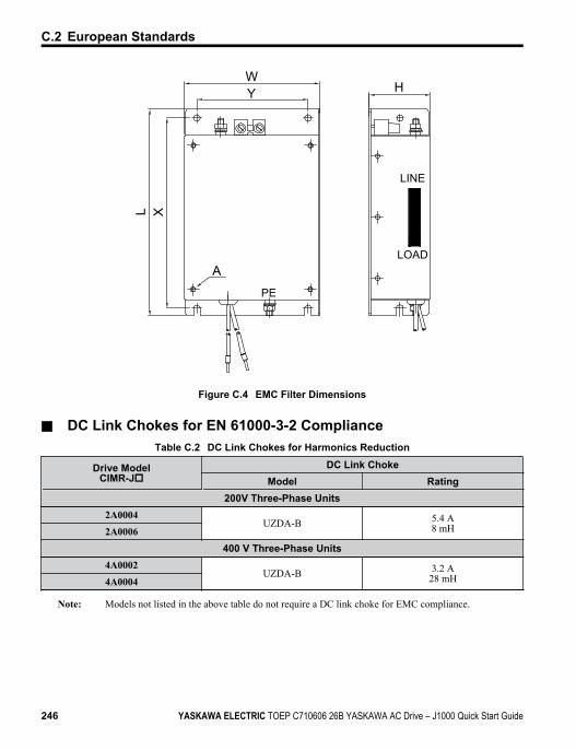
H
XL
WY
LINE
APE
LOAD
Figure C.4 EMC Filter Dimensions
n DC Link Chokes for EN 61000-3-2 ComplianceTable C.2 DC Link Chokes for Harmonics Reduction
Drive ModelCIMR-Jo
DC Link ChokeModel Rating
200V Three-Phase Units2A0004
UZDA-B 5.4 A8 mH2A0006
400 V Three-Phase Units4A0002
UZDA-B 3.2 A28 mH4A0004
Note: Models not listed in the above table do not require a DC link choke for EMC compliance.
C.2 European Standards
246 YASKAWA ELECTRIC TOEP C710606 26B YASKAWA AC Drive – J1000 Quick Start Guide
C.3 UL StandardsThe UL/cUL mark applies to products in the United States and Canada indicates that UL hasperformed product testing and evaluation and determined that their stringent standards forproduct safety have been met. For a product to receive UL certification, all components insidethat product must also receive UL certification.
Figure C.5 UL/cUL Mark
u UL Standards ComplianceThis drive is tested in accordance with UL standard UL508C, E131457 and complies with ULrequirements. The following conditions must be met to maintain compliance when using thisdrive in combination with other equipment:
n Installation AreaDo not install the drive to an area greater than pollution severity 2 (UL standard).
n Ambient Temperature-10 to +40 °C (IP20/NEMA Type 1)-10 to +50 °C (IP20/Open-Chassis)
n Main Circuit Terminal WiringYaskawa recommends using UL-listed copper wires (rated at 75 °C) and closed-loopconnectors or CSA-certified ring connectors sized for the selected wire gauge to maintainproper clearances when wiring the drive. Use the correct crimp tool to install connectors permanufacturer recommendation.The wire gauges listed in Table C.3, Table C.4, and Table C.5 are Yaskawa recommendations.Refer to local codes for proper wire gauge selections.
C.3 UL Standards
YASKAWA ELECTRIC TOEP C710606 26B YASKAWA AC Drive – J1000 Quick Start Guide 247C
Stan
dard
s C
ompl
ianc
e
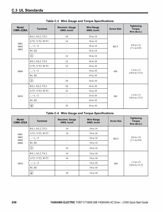
Table C.3 Wire Gauge and Torque Specifications
ModelCIMR-JoBA Terminal Recomm. Gauge
AWG, kcmilWire RangeAWG, kcmil Screw Size
TighteningTorque
N•m (lb.in.)
000100020003
R/L1, S/L2, T/L3 14 18 to 14
M3.5 0.8 to 1.0(7.1 to 8.9)
U/T1, V/T2, W/T3 14 18 to 14
–, +1, +2 – 18 to 14
B1, B2 – 18 to 14
14 18 to 14
0006
R/L1, S/L2, T/L3 12 14 to 10
M4 1.2 to 1.5(10.6 to 13.3)
U/T1, V/T2, W/T3 14 14 to 10
–, +1, +2 – 14 to 10
B1, B2 – 14 to 10
10 14 to 10
0010
R/L1, S/L2, T/L3 10 14 to 10
M4 1.2 to 1.5(10.6 to 13.3)
U/T1, V/T2, W/T3 14 14 to 10
–, +1, +2 – 14 to 10
B1, B2 – 14 to 10
10 14 to 10
Table C.4 Wire Gauge and Torque Specifications
ModelCIMR-Jo2A Terminal Recomm. Gauge
AWG, kcmilWire RangeAWG, kcmil Screw Size
TighteningTorque
N•m (lb.in.)
0001000200040006
R/L1, S/L2, T/L3 14 18 to 14
M3.5 0.8 to 1.0(7.1 to 8.9)
U/T1, V/T2, W/T3 14 18 to 14
–, +1, +2 – 18 to 14
B1, B2 – 18 to 14
14 18 to 14
0010
R/L1, S/L2, T/L3 14 14 to 10
M4 1.2 to 1.5(10.6 to 13.3)
U/T1, V/T2, W/T3 14 14 to 10
–, +1, +2 – 14 to 10
B1, B2 – 14 to 10
10 14 to 10
C.3 UL Standards
248 YASKAWA ELECTRIC TOEP C710606 26B YASKAWA AC Drive – J1000 Quick Start Guide
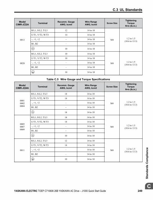
ModelCIMR-Jo2A Terminal Recomm. Gauge
AWG, kcmilWire RangeAWG, kcmil Screw Size
TighteningTorque
N•m (lb.in.)
0012
R/L1, S/L2, T/L3 12 14 to 10
M4 1.2 to 1.5(10.6 to 13.3)
U/T1, V/T2, W/T3 14 14 to 10
–, +1, +2 – 14 to 10
B1, B2 – 14 to 10
10 14 to 10
0020
R/L1, S/L2, T/L3 10 14 to 10
M4 1.2 to 1.5(10.6 to 13.3)
U/T1, V/T2, W/T3 10 14 to 10
–, +1, +2 – 14 to 10
B1, B2 – 14 to 10
10 14 to 10
Table C.5 Wire Gauge and Torque Specifications
ModelCIMR-Jo4A Terminal Recomm. Gauge
AWG, kcmilWire RangeAWG, kcmil Screw Size
TighteningTorque
N•m (lb.in.)
000100020004
R/L1, S/L2, T/L3 14 14 to 10
M4 1.2 to 1.5(10.6 to 13.3)
U/T1, V/T2, W/T3 14 14 to 10
–, +1, +2 – 14 to 10
B1, B2 – 14 to 10
14 14 to 10
000500070009
R/L1, S/L2, T/L3 14 14 to 10
M4 1.2 to 1.5(10.6 to 13.3)
U/T1, V/T2, W/T3 14 14 to 10
–, +1, +2 – 14 to 10
B1, B2 – 14 to 10
10 14 to 10
0011
R/L1, S/L2, T/L3 12 14 to 10
M4 1.2 to 1.5(10.6 to 13.3)
U/T1, V/T2, W/T3 14 14 to 10
–, +1, +2 – 14 to 10
B1, B2 – 14 to 10
10 14 to 10
C.3 UL Standards
YASKAWA ELECTRIC TOEP C710606 26B YASKAWA AC Drive – J1000 Quick Start Guide 249C
Stan
dard
s C
ompl
ianc
e
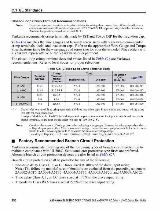
Closed-Loop Crimp Terminal RecommendationsNote: Use crimp insulated terminals or insulated tubing for wiring these connections. Wires should have a
continuous maximum allowable temperature of 75 °C 600 V UL approved vinyl sheathed insulation.Ambient temperature should not exceed 30 °C.
Yaskawa recommends crimp terminals made by JST and Tokyo DIP for the insulation cap.Table C.6 matches the wire gauges and terminal screw sizes with Yaskawa-recommendedcrimp terminals, tools, and insulation caps. Refer to the appropriate Wire Gauge and TorqueSpecifications table for the wire gauge and screw size for your drive model. Place orders witha Yaskawa representative or the Yaskawa sales department.The closed-loop crimp terminal sizes and values listed in Table C.6 are Yaskawarecommendations. Refer to local codes for proper selections.
Table C.6 Closed-Loop Crimp Terminal Sizes
Wire Gauge TerminalScrews
CrimpTerminal
ModelNumber
Tool InsulationCap
Model No.Code <1>
Machine No. Die Jaw
18 AWG M3.5 R1.25-3.5 YA-4 AD-900 TP-003 100-066-217
16 AWG M3.5 R1.25-3.5 YA-4 AD-900 TP-003 100-066-217
14 AWGM3.5 R2-3.5 YA-4 AD-900 TP-003 100-066-218
M4 R2-4 YA-4 AD-900 TP-003 100-054-028
12 / 10 AWG M4 R5.5-4 YA-4 AD-900 TP-005 100-054-029
<1> Codes refer to a set of three crimp terminals and three insulation caps. Prepare input and output wiring usingtwo sets for each connection.Example: Models with 14 AWG for both input and output require one set for input terminals and one set foroutput terminals, so the user should order two sets of [100-066-218].
Note: Consider the amount of voltage drop when selecting wire gauges. Increase the wire gauge when thevoltage drop is greater than 2% of motor rated voltage. Ensure the wire gauge is suitable for the terminalblock. Use the following formula to calculate the amount of voltage drop:Line drop voltage (V) = 3 × wire resistance (Ω/km) × wire length (m) × current (A) × 10-3
n Factory Recommended Branch Circuit ProtectionYaskawa recommends installing one of the following types of branch circuit protection tomaintain compliance with UL508C. Semiconductor protective type fuses are preferred.Alternate branch circuit protection devices are also listed in Table C.7.Branch circuit protection shall be provided by any of the following:• Non-time delay Class J, T, or CC fuses sized at 300% of the drive input rating
Note: The following model/fuse combinations are excluded from the preceding statement:2A0002/A6T6, 2A0004/A6T15, 4A0004/A6T15, 4A0005/A6T20, and 4A0007/A6T25.
• Time delay Class J, T, or CC fuses sized at 175% of the drive input rating• Time-delay Class RK5 fuses sized at 225% of the drive input rating
C.3 UL Standards
250 YASKAWA ELECTRIC TOEP C710606 26B YASKAWA AC Drive – J1000 Quick Start Guide
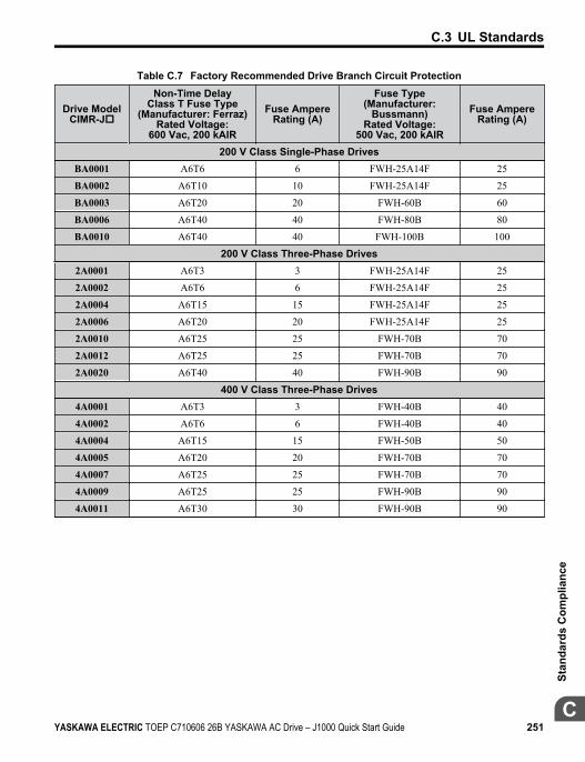
Table C.7 Factory Recommended Drive Branch Circuit Protection
Drive ModelCIMR-Jo
Non-Time DelayClass T Fuse Type
(Manufacturer: Ferraz)Rated Voltage:
600 Vac, 200 kAIR
Fuse AmpereRating (A)
Fuse Type(Manufacturer:
Bussmann)Rated Voltage:
500 Vac, 200 kAIR
Fuse AmpereRating (A)
200 V Class Single-Phase DrivesBA0001 A6T6 6 FWH-25A14F 25
BA0002 A6T10 10 FWH-25A14F 25
BA0003 A6T20 20 FWH-60B 60
BA0006 A6T40 40 FWH-80B 80
BA0010 A6T40 40 FWH-100B 100
200 V Class Three-Phase Drives2A0001 A6T3 3 FWH-25A14F 25
2A0002 A6T6 6 FWH-25A14F 25
2A0004 A6T15 15 FWH-25A14F 25
2A0006 A6T20 20 FWH-25A14F 25
2A0010 A6T25 25 FWH-70B 70
2A0012 A6T25 25 FWH-70B 70
2A0020 A6T40 40 FWH-90B 90
400 V Class Three-Phase Drives4A0001 A6T3 3 FWH-40B 40
4A0002 A6T6 6 FWH-40B 40
4A0004 A6T15 15 FWH-50B 50
4A0005 A6T20 20 FWH-70B 70
4A0007 A6T25 25 FWH-70B 70
4A0009 A6T25 25 FWH-90B 90
4A0011 A6T30 30 FWH-90B 90
C.3 UL Standards
YASKAWA ELECTRIC TOEP C710606 26B YASKAWA AC Drive – J1000 Quick Start Guide 251C
Stan
dard
s C
ompl
ianc
e
n Low Voltage Wiring for Control Circuit TerminalsWire low voltage wires with NEC Class 1 circuit conductors. Refer to national state or localcodes for wiring. Use a class 2 (UL listed) power supply for the control circuit terminal.
Table C.8 Control Circuit Terminal Power SupplyInput / Output Terminal Signal Power Supply Specifications
Multi-function digital inputs S1, S2, S3, S4, S5, SC Use the internal power supply of the drive.Use class 2 for external power supply.
Main frequency reference +V, A1, AC Use the internal power supply of the drive.Use class 2 for external power supply.
n Drive Short-Circuit RatingThis drive has undergone the UL short-circuit test, which certifies that during a short circuitin the power supply the current flow will not rise above 31,000 amps maximum at 240 V for200 V class drives and 480 V for 400 V class drives.• The MCCB and breaker protection and fuse ratings shall be equal to or greater than the
short-circuit tolerance of the power supply being used.• Suitable for use on a circuit capable of delivering not more than 31,000 RMS symmetrical
amperes for 240 V in 200 V class drives (up to 480 V for 400 V class drives) motor overloadprotection.
u Drive Motor Overload ProtectionSet parameter E2-01 (motor rated current) to the appropriate value to enable motor overloadprotection. The internal motor overload protection is UL listed and in accordance with theNEC and CEC.
n E2-01: Motor Rated CurrentSetting Range: Model DependentDefault Setting: Model DependentParameter E2-01 (motor rated current) protects the motor if parameter L1-01 is not set to 0(default is 1, standard induction motor protection enabled).
n L1-01: Motor Overload Protection SelectionThe drive has an electronic overload protection function (oL1) based on time, output currentand output frequency, which protects the motor from overheating. The electronic thermaloverload function is UL-recognized, so it does not require an external thermal overload relayfor single motor operation.This parameter selects the motor overload curve used according to the type of motor applied.
C.3 UL Standards
252 YASKAWA ELECTRIC TOEP C710606 26B YASKAWA AC Drive – J1000 Quick Start Guide
Table C.9 Overload Protection SettingsSetting Description
0 Disabled
1 General Purpose Motor (Standard Fan-Cooled) (default)
2 Drive Dedicated Motor with a Speed Range of 1:10
Disable the electronic overload protection (L1-01 = 0: Disabled) and wire each motor with itsown motor thermal overload when connecting the drive to more than one motor forsimultaneous operation.Enable the motor overload protection (L1-01 = 1 or 2) when connecting the drive to a singlemotor unless there is another means of preventing motor thermal overload. The electronicthermal overload function causes an oL1 fault, which shuts off the output of the drive andprevents additional overheating of the motor. The motor temperature is continually calculatedas long as the drive is powered up.Setting L1-01 = 1 selects a motor with limited cooling capability below rated (base) speedwhen running at 100% load. The oL1 function derates the motor when it is running belowbase speed.Setting L1-01 = 2 selects a motor capable of cooling itself over a 10:1 speed range whenrunning at 100% load. The oL1 function derates the motor when it is running at 1/10 or lessof its rated speed.
n L1-02: Motor Overload Protection TimeSetting Range: 0.1 to 20.0 MinutesFactory Default: 8.0 MinutesThe L1-02 parameter sets the allowed operation time before the oL1 fault occurs when thedrive is running at 60 Hz and 150% of the full load amp rating (E2-01) of the motor. Adjustingthe value of L1-02 can shift the set of oL1 curves up the Y-axis of the diagram below but willnot change the shape of the curves.
C.3 UL Standards
YASKAWA ELECTRIC TOEP C710606 26B YASKAWA AC Drive – J1000 Quick Start Guide 253C
Stan
dard
s C
ompl
ianc
e
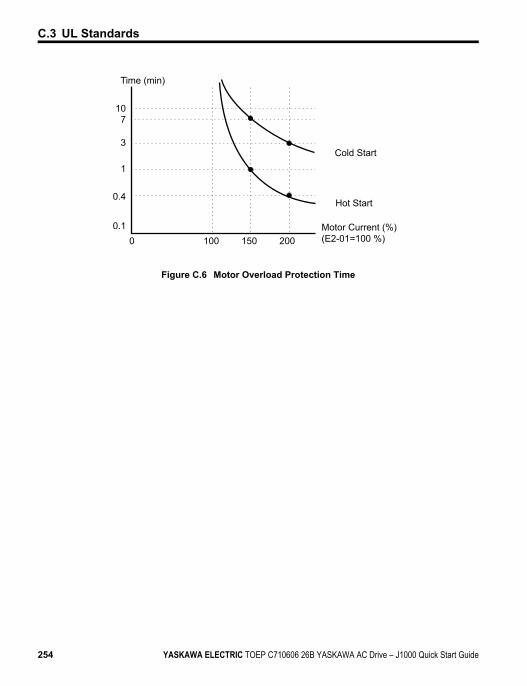
107
3
1
0.4
0.10 100 200150
Cold Start
Hot Start
Motor Current (%) (E2-01=100 %)
Time (min)
Figure C.6 Motor Overload Protection Time
C.3 UL Standards
254 YASKAWA ELECTRIC TOEP C710606 26B YASKAWA AC Drive – J1000 Quick Start Guide
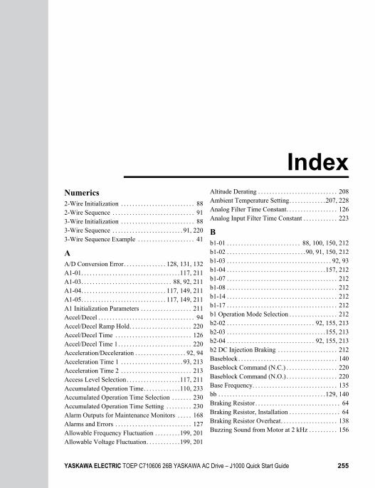
IndexNumerics2-Wire Initialization . . . . . . . . . . . . . . . . . . . . . . . . . . 882-Wire Sequence . . . . . . . . . . . . . . . . . . . . . . . . . . . . . 913-Wire Initialization . . . . . . . . . . . . . . . . . . . . . . . . . . 883-Wire Sequence . . . . . . . . . . . . . . . . . . . . . . . . . 91, 2203-Wire Sequence Example . . . . . . . . . . . . . . . . . . . . 41
AA/D Conversion Error. . . . . . . . . . . . . . . 128, 131, 132A1-01. . . . . . . . . . . . . . . . . . . . . . . . . . . . . . . . . . .117, 211A1-03. . . . . . . . . . . . . . . . . . . . . . . . . . . . . . . . 88, 92, 211A1-04. . . . . . . . . . . . . . . . . . . . . . . . . . . . . . 117, 149, 211A1-05. . . . . . . . . . . . . . . . . . . . . . . . . . . . . . 117, 149, 211A1 Initialization Parameters . . . . . . . . . . . . . . . . . . 211Accel/Decel . . . . . . . . . . . . . . . . . . . . . . . . . . . . . . . . . . 94Accel/Decel Ramp Hold. . . . . . . . . . . . . . . . . . . . . . 220Accel/Decel Time . . . . . . . . . . . . . . . . . . . . . . . . . . . 126Accel/Decel Time 1. . . . . . . . . . . . . . . . . . . . . . . . . . 220Acceleration/Deceleration . . . . . . . . . . . . . . . . . . 92, 94Acceleration Time 1 . . . . . . . . . . . . . . . . . . . . . . 93, 213Acceleration Time 2 . . . . . . . . . . . . . . . . . . . . . . . . . 213Access Level Selection. . . . . . . . . . . . . . . . . . .117, 211Accumulated Operation Time. . . . . . . . . . . . .110, 233Accumulated Operation Time Selection . . . . . . . 230Accumulated Operation Time Setting . . . . . . . . . 230Alarm Outputs for Maintenance Monitors . . . . . 168Alarms and Errors . . . . . . . . . . . . . . . . . . . . . . . . . . . 127Allowable Frequency Fluctuation . . . . . . . . .199, 201Allowable Voltage Fluctuation. . . . . . . . . . . .199, 201
Altitude Derating . . . . . . . . . . . . . . . . . . . . . . . . . . . . 208Ambient Temperature Setting. . . . . . . . . . . . .207, 228Analog Filter Time Constant. . . . . . . . . . . . . . . . . . 126Analog Input Filter Time Constant . . . . . . . . . . . . 223
Bb1-01 . . . . . . . . . . . . . . . . . . . . . . . . . . 88, 100, 150, 212b1-02 . . . . . . . . . . . . . . . . . . . . . . . . . . . .90, 91, 150, 212b1-03 . . . . . . . . . . . . . . . . . . . . . . . . . . . . . . . . . . . . . 92, 93b1-04 . . . . . . . . . . . . . . . . . . . . . . . . . . . . . . . . . . .157, 212b1-07 . . . . . . . . . . . . . . . . . . . . . . . . . . . . . . . . . . . . . . . 212b1-08 . . . . . . . . . . . . . . . . . . . . . . . . . . . . . . . . . . . . . . . 212b1-14 . . . . . . . . . . . . . . . . . . . . . . . . . . . . . . . . . . . . . . . 212b1-17 . . . . . . . . . . . . . . . . . . . . . . . . . . . . . . . . . . . . . . . 212b1 Operation Mode Selection . . . . . . . . . . . . . . . . . 212b2-02 . . . . . . . . . . . . . . . . . . . . . . . . . . . . . . . 92, 155, 213b2-03 . . . . . . . . . . . . . . . . . . . . . . . . . . . . . . . . . . .155, 213b2-04 . . . . . . . . . . . . . . . . . . . . . . . . . . . . . . . 92, 155, 213b2 DC Injection Braking . . . . . . . . . . . . . . . . . . . . . 212Baseblock . . . . . . . . . . . . . . . . . . . . . . . . . . . . . . . . . . . 140Baseblock Command (N.C.) . . . . . . . . . . . . . . . . . . 220Baseblock Command (N.O.) . . . . . . . . . . . . . . . . . . 220Base Frequency. . . . . . . . . . . . . . . . . . . . . . . . . . . . . . 135bb . . . . . . . . . . . . . . . . . . . . . . . . . . . . . . . . . . . . . .129, 140Braking Resistor . . . . . . . . . . . . . . . . . . . . . . . . . . . . . . 64Braking Resistor, Installation . . . . . . . . . . . . . . . . . . 64Braking Resistor Overheat. . . . . . . . . . . . . . . . . . . . 138Buzzing Sound from Motor at 2 kHz . . . . . . . . . . 156
YASKAWA ELECTRIC TOEP C710606 26B YASKAWA AC Drive – J1000 Quick Start Guide 255
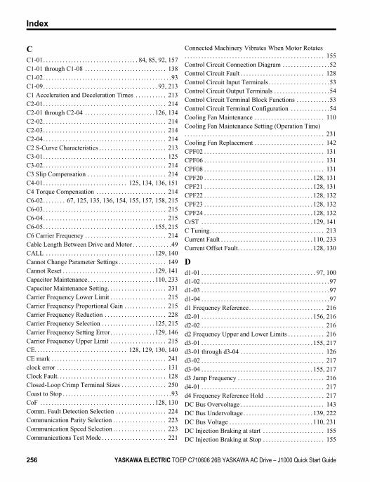
CC1-01. . . . . . . . . . . . . . . . . . . . . . . . . . . . . . . . . . 84, 85, 92, 157C1-01 through C1-08 . . . . . . . . . . . . . . . . . . . . . . . . . . . . . 138C1-02. . . . . . . . . . . . . . . . . . . . . . . . . . . . . . . . . . . . . . . . . . . . . .93C1-09. . . . . . . . . . . . . . . . . . . . . . . . . . . . . . . . . . . . . . . . . 93, 213C1 Acceleration and Deceleration Times . . . . . . . . . . . 213C2-01. . . . . . . . . . . . . . . . . . . . . . . . . . . . . . . . . . . . . . . . . . . . 214C2-01 through C2-04 . . . . . . . . . . . . . . . . . . . . . . . . . 126, 134C2-02. . . . . . . . . . . . . . . . . . . . . . . . . . . . . . . . . . . . . . . . . . . . 214C2-03. . . . . . . . . . . . . . . . . . . . . . . . . . . . . . . . . . . . . . . . . . . . 214C2-04. . . . . . . . . . . . . . . . . . . . . . . . . . . . . . . . . . . . . . . . . . . . 214C2 S-Curve Characteristics . . . . . . . . . . . . . . . . . . . . . . . . 213C3-01. . . . . . . . . . . . . . . . . . . . . . . . . . . . . . . . . . . . . . . . . . . . 125C3-02. . . . . . . . . . . . . . . . . . . . . . . . . . . . . . . . . . . . . . . . . . . . 214C3 Slip Compensation . . . . . . . . . . . . . . . . . . . . . . . . . . . . 214C4-01. . . . . . . . . . . . . . . . . . . . . . . . . . . . . . 125, 134, 136, 151C4 Torque Compensation . . . . . . . . . . . . . . . . . . . . . . . . . 214C6-02. . . . . . . . 67, 125, 135, 136, 154, 155, 157, 158, 215C6-03. . . . . . . . . . . . . . . . . . . . . . . . . . . . . . . . . . . . . . . . . . . . 215C6-04. . . . . . . . . . . . . . . . . . . . . . . . . . . . . . . . . . . . . . . . . . . . 215C6-05. . . . . . . . . . . . . . . . . . . . . . . . . . . . . . . . . . . . . . . . 155, 215C6 Carrier Frequency . . . . . . . . . . . . . . . . . . . . . . . . . . . . . 214Cable Length Between Drive and Motor . . . . . . . . . . . . . .49CALL . . . . . . . . . . . . . . . . . . . . . . . . . . . . . . . . . . . . . . . 129, 140Cannot Change Parameter Settings . . . . . . . . . . . . . . . . . 149Cannot Reset . . . . . . . . . . . . . . . . . . . . . . . . . . . . . . . . . 129, 141Capacitor Maintenance . . . . . . . . . . . . . . . . . . . . . . . . 110, 233Capacitor Maintenance Setting. . . . . . . . . . . . . . . . . . . . . 231Carrier Frequency Lower Limit . . . . . . . . . . . . . . . . . . . . 215Carrier Frequency Proportional Gain . . . . . . . . . . . . . . . 215Carrier Frequency Reduction . . . . . . . . . . . . . . . . . . . . . . 228Carrier Frequency Selection . . . . . . . . . . . . . . . . . . . 125, 215Carrier Frequency Setting Error . . . . . . . . . . . . . . . . 129, 146Carrier Frequency Upper Limit . . . . . . . . . . . . . . . . . . . . 215CE. . . . . . . . . . . . . . . . . . . . . . . . . . . . . . . . . 128, 129, 130, 140CE mark . . . . . . . . . . . . . . . . . . . . . . . . . . . . . . . . . . . . . . . . . 241clock error . . . . . . . . . . . . . . . . . . . . . . . . . . . . . . . . . . . . . . . 131Clock Fault. . . . . . . . . . . . . . . . . . . . . . . . . . . . . . . . . . . . . . . 128Closed-Loop Crimp Terminal Sizes . . . . . . . . . . . . . . . . 250Coast to Stop . . . . . . . . . . . . . . . . . . . . . . . . . . . . . . . . . . . . . . .93CoF . . . . . . . . . . . . . . . . . . . . . . . . . . . . . . . . . . . . . . . . . 128, 130Comm. Fault Detection Selection . . . . . . . . . . . . . . . . . . 224Communication Parity Selection . . . . . . . . . . . . . . . . . . . 223Communication Speed Selection . . . . . . . . . . . . . . . . . . . 223Communications Test Mode . . . . . . . . . . . . . . . . . . . . . . . 221
Connected Machinery Vibrates When Motor Rotates. . . . . . . . . . . . . . . . . . . . . . . . . . . . . . . . . . . . . . . . . . . . . . . . . . 155Control Circuit Connection Diagram . . . . . . . . . . . . . . . . .52Control Circuit Fault . . . . . . . . . . . . . . . . . . . . . . . . . . . . . . 128Control Circuit Input Terminals . . . . . . . . . . . . . . . . . . . . . .53Control Circuit Output Terminals . . . . . . . . . . . . . . . . . . . .54Control Circuit Terminal Block Functions . . . . . . . . . . . .53Control Circuit Terminal Configuration . . . . . . . . . . . . . .54Cooling Fan Maintenance . . . . . . . . . . . . . . . . . . . . . . . . . 110Cooling Fan Maintenance Setting (Operation Time). . . . . . . . . . . . . . . . . . . . . . . . . . . . . . . . . . . . . . . . . . . . . . . . . . 231Cooling Fan Replacement . . . . . . . . . . . . . . . . . . . . . . . . . 142CPF02 . . . . . . . . . . . . . . . . . . . . . . . . . . . . . . . . . . . . . . . . . . . 131CPF06 . . . . . . . . . . . . . . . . . . . . . . . . . . . . . . . . . . . . . . . . . . . 131CPF08 . . . . . . . . . . . . . . . . . . . . . . . . . . . . . . . . . . . . . . . . . . . 131CPF20 . . . . . . . . . . . . . . . . . . . . . . . . . . . . . . . . . . . . . . . 128, 131CPF21 . . . . . . . . . . . . . . . . . . . . . . . . . . . . . . . . . . . . . . . 128, 131CPF22 . . . . . . . . . . . . . . . . . . . . . . . . . . . . . . . . . . . . . . . 128, 132CPF23 . . . . . . . . . . . . . . . . . . . . . . . . . . . . . . . . . . . . . . . 128, 132CPF24 . . . . . . . . . . . . . . . . . . . . . . . . . . . . . . . . . . . . . . . 128, 132CrST . . . . . . . . . . . . . . . . . . . . . . . . . . . . . . . . . . . . . . . . 129, 141C Tuning. . . . . . . . . . . . . . . . . . . . . . . . . . . . . . . . . . . . . . . . . 213Current Fault . . . . . . . . . . . . . . . . . . . . . . . . . . . . . . . . . 110, 233Current Offset Fault. . . . . . . . . . . . . . . . . . . . . . . . . . . 128, 130
Dd1-01 . . . . . . . . . . . . . . . . . . . . . . . . . . . . . . . . . . . . . . . . . 97, 100d1-02 . . . . . . . . . . . . . . . . . . . . . . . . . . . . . . . . . . . . . . . . . . . . . .97d1-03 . . . . . . . . . . . . . . . . . . . . . . . . . . . . . . . . . . . . . . . . . . . . . .97d1-04 . . . . . . . . . . . . . . . . . . . . . . . . . . . . . . . . . . . . . . . . . . . . . .97d1 Frequency Reference. . . . . . . . . . . . . . . . . . . . . . . . . . . 216d2-01 . . . . . . . . . . . . . . . . . . . . . . . . . . . . . . . . . . . . . . . . 156, 216d2-02 . . . . . . . . . . . . . . . . . . . . . . . . . . . . . . . . . . . . . . . . . . . . 216d2 Frequency Upper and Lower Limits . . . . . . . . . . . . . 216d3-01 . . . . . . . . . . . . . . . . . . . . . . . . . . . . . . . . . . . . . . . . 155, 217d3-01 through d3-04 . . . . . . . . . . . . . . . . . . . . . . . . . . . . . . 126d3-02 . . . . . . . . . . . . . . . . . . . . . . . . . . . . . . . . . . . . . . . . . . . . 217d3-04 . . . . . . . . . . . . . . . . . . . . . . . . . . . . . . . . . . . . . . . . 155, 217d3 Jump Frequency . . . . . . . . . . . . . . . . . . . . . . . . . . . . . . . 216d4-01 . . . . . . . . . . . . . . . . . . . . . . . . . . . . . . . . . . . . . . . . . . . . 217d4 Frequency Reference Hold . . . . . . . . . . . . . . . . . . . . . 217DC Bus Overvoltage . . . . . . . . . . . . . . . . . . . . . . . . . . . . . . 143DC Bus Undervoltage . . . . . . . . . . . . . . . . . . . . . . . . . 139, 222DC Bus Voltage . . . . . . . . . . . . . . . . . . . . . . . . . . . . . . 110, 231DC Injection Braking at start . . . . . . . . . . . . . . . . . . . . . . 155DC Injection Braking at Stop . . . . . . . . . . . . . . . . . . . . . . 155
Index
256 YASKAWA ELECTRIC TOEP C710606 26B YASKAWA AC Drive – J1000 Quick Start Guide
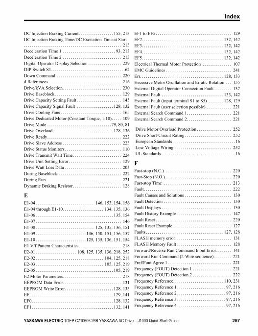
DC Injection Braking Current. . . . . . . . . . . . . . . . . . 155, 213DC Injection Braking Time/DC Excitation Time at Start. . . . . . . . . . . . . . . . . . . . . . . . . . . . . . . . . . . . . . . . . . . . . . . . . . 213Deceleration Time 1 . . . . . . . . . . . . . . . . . . . . . . . . . . . 93, 213Deceleration Time 2 . . . . . . . . . . . . . . . . . . . . . . . . . . . . . . 213Digital Operator Display Selection . . . . . . . . . . . . . . . . . 229DIP Switch S1. . . . . . . . . . . . . . . . . . . . . . . . . . . . . . . . . . . . . .62Down Command . . . . . . . . . . . . . . . . . . . . . . . . . . . . . . . . . 220d References . . . . . . . . . . . . . . . . . . . . . . . . . . . . . . . . . . . . . 216Drive/kVA Selection. . . . . . . . . . . . . . . . . . . . . . . . . . . . . . 230Drive Baseblock . . . . . . . . . . . . . . . . . . . . . . . . . . . . . . . . . . 129Drive Capacity Setting Fault . . . . . . . . . . . . . . . . . . . . . . . 145Drive Capacity Signal Fault . . . . . . . . . . . . . . . . . . . 128, 132Drive Cooling Fans . . . . . . . . . . . . . . . . . . . . . . . . . . . . . . . 165Drive Dedicated Motor (Constant Torque, 1:10). . . . . 109Drive Mode . . . . . . . . . . . . . . . . . . . . . . . . . . . . . . . . .79, 80, 81Drive Overload . . . . . . . . . . . . . . . . . . . . . . . . . . . . . . . 128, 136Drive Ready. . . . . . . . . . . . . . . . . . . . . . . . . . . . . . . . . . . . . . 222Drive Slave Address . . . . . . . . . . . . . . . . . . . . . . . . . . . . . . 223Drive Status Monitors . . . . . . . . . . . . . . . . . . . . . . . . . . . . . 110Drive Transmit Wait Time. . . . . . . . . . . . . . . . . . . . . . . . . 224Drive Unit Setting Error . . . . . . . . . . . . . . . . . . . . . . . . . . . 129Drive Watt Loss Data . . . . . . . . . . . . . . . . . . . . . . . . . . . . . 205During Baseblock. . . . . . . . . . . . . . . . . . . . . . . . . . . . . . . . . 222During Run . . . . . . . . . . . . . . . . . . . . . . . . . . . . . . . . . . . . . . 221Dynamic Braking Resistor. . . . . . . . . . . . . . . . . . . . . . . . . 128
EE1-04 . . . . . . . . . . . . . . . . . . . . . . . . . . . . . . 146, 153, 154, 156E1-04 through E1-10. . . . . . . . . . . . . . . . . . . . . 134, 135, 136E1-06 . . . . . . . . . . . . . . . . . . . . . . . . . . . . . . . . . . . . . . . . 135, 154E1-07 . . . . . . . . . . . . . . . . . . . . . . . . . . . . . . . . . . . . . . . . . . . . 146E1-08 . . . . . . . . . . . . . . . . . . . . . . . . . . . . . . 125, 135, 136, 151E1-09 . . . . . . . . . . . . . . . . . . . . . . . . . . 146, 150, 151, 156, 157E1-10 . . . . . . . . . . . . . . . . . . . . . . . . . . 125, 135, 136, 151, 154E1 V/f Pattern Characteristics. . . . . . . . . . . . . . . . . . . . . . 218E2-01 . . . . . . . . . . . . . . . . . . . . . 108, 125, 135, 136, 218, 252E2-02 . . . . . . . . . . . . . . . . . . . . . . . . . . . . . . . . . . . 104, 125, 218E2-03 . . . . . . . . . . . . . . . . . . . . . . . . . . . . . . . . . . . 105, 125, 219E2-05 . . . . . . . . . . . . . . . . . . . . . . . . . . . . . . . . . . . . . . . . 105, 219E2 Motor Parameters. . . . . . . . . . . . . . . . . . . . . . . . . . . . . . 218EEPROM Data Error. . . . . . . . . . . . . . . . . . . . . . . . . . . . . . 131EEPROM Write Error. . . . . . . . . . . . . . . . . . . . . . . . . 128, 133EF. . . . . . . . . . . . . . . . . . . . . . . . . . . . . . . . . . . . . . . . . . . 129, 141EF0. . . . . . . . . . . . . . . . . . . . . . . . . . . . . . . . . . . . . . . . . . 128, 132EF1. . . . . . . . . . . . . . . . . . . . . . . . . . . . . . . . . . . . . . . . . . 132, 141
EF1 to EF5. . . . . . . . . . . . . . . . . . . . . . . . . . . . . . . . . . . . . . . 129EF2. . . . . . . . . . . . . . . . . . . . . . . . . . . . . . . . . . . . . . . . . . 132, 142EF3. . . . . . . . . . . . . . . . . . . . . . . . . . . . . . . . . . . . . . . . . . 132, 142EF4. . . . . . . . . . . . . . . . . . . . . . . . . . . . . . . . . . . . . . . . . . 132, 142EF5. . . . . . . . . . . . . . . . . . . . . . . . . . . . . . . . . . . . . . . . . . 132, 142Electrical Thermal Motor Protection . . . . . . . . . . . . . . . 107EMC Guidelines . . . . . . . . . . . . . . . . . . . . . . . . . . . . . . . . . . 241Err. . . . . . . . . . . . . . . . . . . . . . . . . . . . . . . . . . . . . . . . . . . 128, 133Excessive Motor Oscillation and Erratic Rotation . . . 155External Digital Operator Connection Fault . . . . . . . . . 137External Fault . . . . . . . . . . . . . . . . . . . . . . . . . . . . . . . . 133, 142External Fault (input terminal S1 to S5) . . . . . . . . 128, 129External Fault (user selection possible) . . . . . . . . . . . . . 221External Search Command 1. . . . . . . . . . . . . . . . . . . . . . . 221External Search Command 2. . . . . . . . . . . . . . . . . . . . . . . 221
Drive Motor Overload Protection. . . . . . . . . . . . . . . . . . 252 Drive Short-Circuit Rating . . . . . . . . . . . . . . . . . . . . . . . . 252 European Standards . . . . . . . . . . . . . . . . . . . . . . . . . . . . . . . .16 Low Voltage Wiring . . . . . . . . . . . . . . . . . . . . . . . . . . . . . 252 UL Standards . . . . . . . . . . . . . . . . . . . . . . . . . . . . . . . . . . . . . .16
FFast-stop (N.C.) . . . . . . . . . . . . . . . . . . . . . . . . . . . . . . . . . . 220Fast-Stop (N.O.) . . . . . . . . . . . . . . . . . . . . . . . . . . . . . . . . . . 220Fast-stop Time . . . . . . . . . . . . . . . . . . . . . . . . . . . . . . . . . . . 213Fault. . . . . . . . . . . . . . . . . . . . . . . . . . . . . . . . . . . . . . . . . . . . . 222Fault Causes and Solutions . . . . . . . . . . . . . . . . . . . . . . . . 130Fault Detection . . . . . . . . . . . . . . . . . . . . . . . . . . . . . . . . . . . 130Fault Displays . . . . . . . . . . . . . . . . . . . . . . . . . . . . . . . . . . . . 130Fault History Example . . . . . . . . . . . . . . . . . . . . . . . . . . . . 147Fault Reset . . . . . . . . . . . . . . . . . . . . . . . . . . . . . . . . . . . . . . . 220Fault Reset Example . . . . . . . . . . . . . . . . . . . . . . . . . . . . . . 127Faults . . . . . . . . . . . . . . . . . . . . . . . . . . . . . . . . . . . . . . . . 127, 128FLASH memory error. . . . . . . . . . . . . . . . . . . . . . . . . . . . . 131FLASH Memory Fault . . . . . . . . . . . . . . . . . . . . . . . . . . . . 128Forward/Reverse Run Command Input Error. . . . . . . . 141Forward Run Command (2-Wire sequence) . . . . . . . . . 221Fref/Fout Agree 1. . . . . . . . . . . . . . . . . . . . . . . . . . . . . . . . . 221Frequency (FOUT) Detection 1 . . . . . . . . . . . . . . . . . . . . 221Frequency (FOUT) Detection 2 . . . . . . . . . . . . . . . . . . . . 222Frequency Reference. . . . . . . . . . . . . . . . . . . . . . . . . . 110, 231Frequency Reference 1 . . . . . . . . . . . . . . . . . . . . . . . . . 97, 216Frequency Reference 2 . . . . . . . . . . . . . . . . . . . . . . . . . 97, 216Frequency Reference 3 . . . . . . . . . . . . . . . . . . . . . . . . . 97, 216Frequency Reference 4 . . . . . . . . . . . . . . . . . . . . . . . . . 97, 216
Index
YASKAWA ELECTRIC TOEP C710606 26B YASKAWA AC Drive – J1000 Quick Start Guide 257
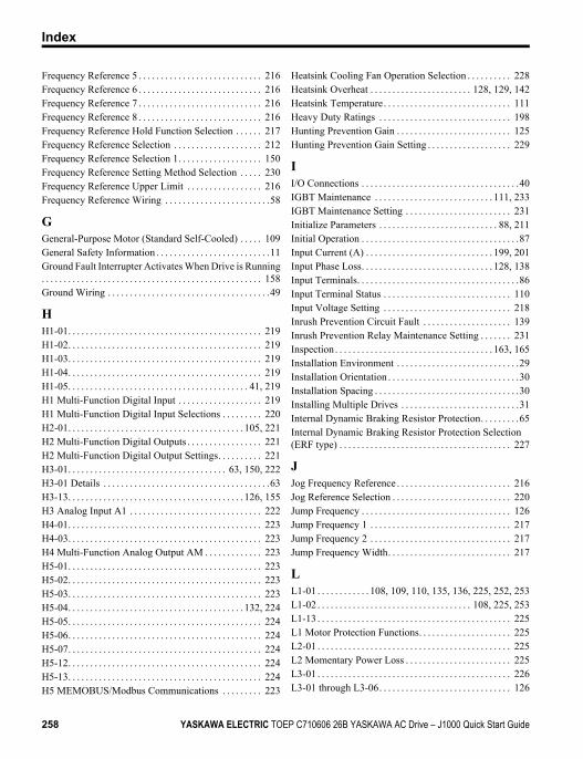
Frequency Reference 5 . . . . . . . . . . . . . . . . . . . . . . . . . . . . 216Frequency Reference 6 . . . . . . . . . . . . . . . . . . . . . . . . . . . . 216Frequency Reference 7 . . . . . . . . . . . . . . . . . . . . . . . . . . . . 216Frequency Reference 8 . . . . . . . . . . . . . . . . . . . . . . . . . . . . 216Frequency Reference Hold Function Selection . . . . . . 217Frequency Reference Selection . . . . . . . . . . . . . . . . . . . . 212Frequency Reference Selection 1. . . . . . . . . . . . . . . . . . . 150Frequency Reference Setting Method Selection . . . . . 230Frequency Reference Upper Limit . . . . . . . . . . . . . . . . . 216Frequency Reference Wiring . . . . . . . . . . . . . . . . . . . . . . . .58
GGeneral-Purpose Motor (Standard Self-Cooled) . . . . . 109General Safety Information . . . . . . . . . . . . . . . . . . . . . . . . . .11Ground Fault Interrupter Activates When Drive is Running. . . . . . . . . . . . . . . . . . . . . . . . . . . . . . . . . . . . . . . . . . . . . . . . . . 158Ground Wiring . . . . . . . . . . . . . . . . . . . . . . . . . . . . . . . . . . . . .49
HH1-01. . . . . . . . . . . . . . . . . . . . . . . . . . . . . . . . . . . . . . . . . . . . 219H1-02. . . . . . . . . . . . . . . . . . . . . . . . . . . . . . . . . . . . . . . . . . . . 219H1-03. . . . . . . . . . . . . . . . . . . . . . . . . . . . . . . . . . . . . . . . . . . . 219H1-04. . . . . . . . . . . . . . . . . . . . . . . . . . . . . . . . . . . . . . . . . . . . 219H1-05. . . . . . . . . . . . . . . . . . . . . . . . . . . . . . . . . . . . . . . . . 41, 219H1 Multi-Function Digital Input . . . . . . . . . . . . . . . . . . . 219H1 Multi-Function Digital Input Selections . . . . . . . . . 220H2-01. . . . . . . . . . . . . . . . . . . . . . . . . . . . . . . . . . . . . . . . 105, 221H2 Multi-Function Digital Outputs . . . . . . . . . . . . . . . . . 221H2 Multi-Function Digital Output Settings. . . . . . . . . . 221H3-01. . . . . . . . . . . . . . . . . . . . . . . . . . . . . . . . . . . . 63, 150, 222H3-01 Details . . . . . . . . . . . . . . . . . . . . . . . . . . . . . . . . . . . . . .63H3-13. . . . . . . . . . . . . . . . . . . . . . . . . . . . . . . . . . . . . . . . 126, 155H3 Analog Input A1 . . . . . . . . . . . . . . . . . . . . . . . . . . . . . . 222H4-01. . . . . . . . . . . . . . . . . . . . . . . . . . . . . . . . . . . . . . . . . . . . 223H4-03. . . . . . . . . . . . . . . . . . . . . . . . . . . . . . . . . . . . . . . . . . . . 223H4 Multi-Function Analog Output AM . . . . . . . . . . . . . 223H5-01. . . . . . . . . . . . . . . . . . . . . . . . . . . . . . . . . . . . . . . . . . . . 223H5-02. . . . . . . . . . . . . . . . . . . . . . . . . . . . . . . . . . . . . . . . . . . . 223H5-03. . . . . . . . . . . . . . . . . . . . . . . . . . . . . . . . . . . . . . . . . . . . 223H5-04. . . . . . . . . . . . . . . . . . . . . . . . . . . . . . . . . . . . . . . . 132, 224H5-05. . . . . . . . . . . . . . . . . . . . . . . . . . . . . . . . . . . . . . . . . . . . 224H5-06. . . . . . . . . . . . . . . . . . . . . . . . . . . . . . . . . . . . . . . . . . . . 224H5-07. . . . . . . . . . . . . . . . . . . . . . . . . . . . . . . . . . . . . . . . . . . . 224H5-12. . . . . . . . . . . . . . . . . . . . . . . . . . . . . . . . . . . . . . . . . . . . 224H5-13. . . . . . . . . . . . . . . . . . . . . . . . . . . . . . . . . . . . . . . . . . . . 224H5 MEMOBUS/Modbus Communications . . . . . . . . . 223
Heatsink Cooling Fan Operation Selection . . . . . . . . . . 228Heatsink Overheat . . . . . . . . . . . . . . . . . . . . . . . 128, 129, 142Heatsink Temperature. . . . . . . . . . . . . . . . . . . . . . . . . . . . . 111Heavy Duty Ratings . . . . . . . . . . . . . . . . . . . . . . . . . . . . . . 198Hunting Prevention Gain . . . . . . . . . . . . . . . . . . . . . . . . . . 125Hunting Prevention Gain Setting . . . . . . . . . . . . . . . . . . . 229
II/O Connections . . . . . . . . . . . . . . . . . . . . . . . . . . . . . . . . . . . .40IGBT Maintenance . . . . . . . . . . . . . . . . . . . . . . . . . . . 111, 233IGBT Maintenance Setting . . . . . . . . . . . . . . . . . . . . . . . . 231Initialize Parameters . . . . . . . . . . . . . . . . . . . . . . . . . . . 88, 211Initial Operation . . . . . . . . . . . . . . . . . . . . . . . . . . . . . . . . . . . .87Input Current (A) . . . . . . . . . . . . . . . . . . . . . . . . . . . . . 199, 201Input Phase Loss. . . . . . . . . . . . . . . . . . . . . . . . . . . . . . 128, 138Input Terminals. . . . . . . . . . . . . . . . . . . . . . . . . . . . . . . . . . . . .86Input Terminal Status . . . . . . . . . . . . . . . . . . . . . . . . . . . . . 110Input Voltage Setting . . . . . . . . . . . . . . . . . . . . . . . . . . . . . 218Inrush Prevention Circuit Fault . . . . . . . . . . . . . . . . . . . . 139Inrush Prevention Relay Maintenance Setting . . . . . . . 231Inspection . . . . . . . . . . . . . . . . . . . . . . . . . . . . . . . . . . . . 163, 165Installation Environment . . . . . . . . . . . . . . . . . . . . . . . . . . . .29Installation Orientation . . . . . . . . . . . . . . . . . . . . . . . . . . . . . .30Installation Spacing . . . . . . . . . . . . . . . . . . . . . . . . . . . . . . . . .30Installing Multiple Drives . . . . . . . . . . . . . . . . . . . . . . . . . . .31Internal Dynamic Braking Resistor Protection. . . . . . . . .65Internal Dynamic Braking Resistor Protection Selection (ERF type) . . . . . . . . . . . . . . . . . . . . . . . . . . . . . . . . . . . . . . . 227
JJog Frequency Reference . . . . . . . . . . . . . . . . . . . . . . . . . . 216Jog Reference Selection . . . . . . . . . . . . . . . . . . . . . . . . . . . 220Jump Frequency . . . . . . . . . . . . . . . . . . . . . . . . . . . . . . . . . . 126Jump Frequency 1 . . . . . . . . . . . . . . . . . . . . . . . . . . . . . . . . 217Jump Frequency 2 . . . . . . . . . . . . . . . . . . . . . . . . . . . . . . . . 217Jump Frequency Width. . . . . . . . . . . . . . . . . . . . . . . . . . . . 217
LL1-01 . . . . . . . . . . . . 108, 109, 110, 135, 136, 225, 252, 253L1-02 . . . . . . . . . . . . . . . . . . . . . . . . . . . . . . . . . . . 108, 225, 253L1-13 . . . . . . . . . . . . . . . . . . . . . . . . . . . . . . . . . . . . . . . . . . . . 225L1 Motor Protection Functions. . . . . . . . . . . . . . . . . . . . . 225L2-01 . . . . . . . . . . . . . . . . . . . . . . . . . . . . . . . . . . . . . . . . . . . . 225L2 Momentary Power Loss . . . . . . . . . . . . . . . . . . . . . . . . 225L3-01 . . . . . . . . . . . . . . . . . . . . . . . . . . . . . . . . . . . . . . . . . . . . 226L3-01 through L3-06. . . . . . . . . . . . . . . . . . . . . . . . . . . . . . 126
Index
258 YASKAWA ELECTRIC TOEP C710606 26B YASKAWA AC Drive – J1000 Quick Start Guide
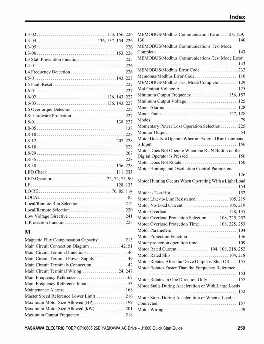
L3-02 . . . . . . . . . . . . . . . . . . . . . . . . . . . . . . . . . . . 153, 156, 226L3-04 . . . . . . . . . . . . . . . . . . . . . . . . . . . . . . 136, 137, 154, 226L3-05 . . . . . . . . . . . . . . . . . . . . . . . . . . . . . . . . . . . . . . . . . . . . 226L3-06 . . . . . . . . . . . . . . . . . . . . . . . . . . . . . . . . . . . . . . . . 153, 226L3 Stall Prevention Function . . . . . . . . . . . . . . . . . . . . . . 225L4-01 . . . . . . . . . . . . . . . . . . . . . . . . . . . . . . . . . . . . . . . . . . . . 226L4 Frequency Detection . . . . . . . . . . . . . . . . . . . . . . . . . . . 226L5-01 . . . . . . . . . . . . . . . . . . . . . . . . . . . . . . . . . . . . . . . . 143, 227L5 Fault Reset . . . . . . . . . . . . . . . . . . . . . . . . . . . . . . . . . . . . 227L6-01 . . . . . . . . . . . . . . . . . . . . . . . . . . . . . . . . . . . . . . . . . . . . 227L6-02 . . . . . . . . . . . . . . . . . . . . . . . . . . . . . . . . . . . 136, 143, 227L6-03 . . . . . . . . . . . . . . . . . . . . . . . . . . . . . . . . . . . 136, 143, 227L6 Overtorque Detection . . . . . . . . . . . . . . . . . . . . . . . . . . 227L8: Hardware Protection . . . . . . . . . . . . . . . . . . . . . . . . . . 227L8-01 . . . . . . . . . . . . . . . . . . . . . . . . . . . . . . . . . . . . . . . . 138, 227L8-05 . . . . . . . . . . . . . . . . . . . . . . . . . . . . . . . . . . . . . . . . . . . . 138L8-10 . . . . . . . . . . . . . . . . . . . . . . . . . . . . . . . . . . . . . . . . . . . . 228L8-12 . . . . . . . . . . . . . . . . . . . . . . . . . . . . . . . . . . . . . . . . 207, 228L8-18 . . . . . . . . . . . . . . . . . . . . . . . . . . . . . . . . . . . . . . . . . . . . 228L8-29 . . . . . . . . . . . . . . . . . . . . . . . . . . . . . . . . . . . . . . . . . . . . 207L8-35 . . . . . . . . . . . . . . . . . . . . . . . . . . . . . . . . . . . . . . . . . . . . 228L8-38 . . . . . . . . . . . . . . . . . . . . . . . . . . . . . . . . . . . . . . . . 156, 228LED Check . . . . . . . . . . . . . . . . . . . . . . . . . . . . . . . . . . 111, 233LED Operator . . . . . . . . . . . . . . . . . . . . . . . . . . . 22, 74, 75, 90LF. . . . . . . . . . . . . . . . . . . . . . . . . . . . . . . . . . . . . . . . . . . 128, 133LO/RE. . . . . . . . . . . . . . . . . . . . . . . . . . . . . . . . . . . . 76, 85, 114LOCAL. . . . . . . . . . . . . . . . . . . . . . . . . . . . . . . . . . . . . . . . . . . .85Local/Remote Run Selection. . . . . . . . . . . . . . . . . . . . . . . 212Local/Remote Selection . . . . . . . . . . . . . . . . . . . . . . . . . . . 220Low Voltage Directive . . . . . . . . . . . . . . . . . . . . . . . . . . . . 241L Protection Function . . . . . . . . . . . . . . . . . . . . . . . . . . . . . 225
MMagnetic Flux Compensation Capacity . . . . . . . . . . . . . 213Main Circuit Connection Diagram . . . . . . . . . . . . . . . 42, 51Main Circuit Terminal Functions. . . . . . . . . . . . . . . . . . . . .46Main Circuit Terminal Power Supply. . . . . . . . . . . . . . . . .49Main Circuit Terminals Connection . . . . . . . . . . . . . . . . . .42Main Circuit Terminal Wiring . . . . . . . . . . . . . . . . . . 24, 247Main Frequency Reference . . . . . . . . . . . . . . . . . . . . . . . . . .62Main Frequency Reference Input. . . . . . . . . . . . . . . . . . . . .53Maintenance Alarms . . . . . . . . . . . . . . . . . . . . . . . . . . . . . . 168Master Speed Reference Lower Limit . . . . . . . . . . . . . . 216Maximum Motor Size Allowed (HP) . . . . . . . . . . . . . . . 199Maximum Motor Size Allowed (kW). . . . . . . . . . . . . . . 201Maximum Output Frequency . . . . . . . . . . . . . . . . . . . . . . 218
MEMOBUS/Modbus Communication Error . . .128, 129, 130, 140MEMOBUS/Modbus Communications Test Mode Complete . . . . . . . . . . . . . . . . . . . . . . . . . . . . . . . . . . . . . . . . 143MEMOBUS/Modbus Communications Test Mode Error. . . . . . . . . . . . . . . . . . . . . . . . . . . . . . . . . . . . . . . . . . . . . . . . . . 143MEMOBUS/Modbus Error Code . . . . . . . . . . . . . . . . . . 232Memobus/Modbus Error Code . . . . . . . . . . . . . . . . . . . . . 110MEMOBUS/Modbus Test Mode Complete . . . . . . . . . 129Mid Output Voltage A . . . . . . . . . . . . . . . . . . . . . . . . . . . . 125Minimum Output Frequency. . . . . . . . . . . . . . . . . . . 156, 157Minimum Output Voltage . . . . . . . . . . . . . . . . . . . . . . . . . 125Minor Alarms . . . . . . . . . . . . . . . . . . . . . . . . . . . . . . . . . . . . 128Minor Faults . . . . . . . . . . . . . . . . . . . . . . . . . . . . . . . . . 127, 128Modes . . . . . . . . . . . . . . . . . . . . . . . . . . . . . . . . . . . . . . . . . . . . .79Momentary Power Loss Operation Selection . . . . . . . . 225Monitor Output . . . . . . . . . . . . . . . . . . . . . . . . . . . . . . . . . . . . .54Motor Does Not Operate When an External Run Command is Input . . . . . . . . . . . . . . . . . . . . . . . . . . . . . . . . . . . . . . . . . . 156Motor Does Not Operate When the RUN Button on the Digital Operator is Pressed . . . . . . . . . . . . . . . . . . . . . . . . 156Motor Does Not Rotate. . . . . . . . . . . . . . . . . . . . . . . . . . . . 150Motor Hunting and Oscillation Control Parameters. . . . . . . . . . . . . . . . . . . . . . . . . . . . . . . . . . . . . . . . . . . . . . . . . . 126Motor Hunting Occurs When Operating With a Light Load. . . . . . . . . . . . . . . . . . . . . . . . . . . . . . . . . . . . . . . . . . . . . . . . . . 154Motor is Too Hot . . . . . . . . . . . . . . . . . . . . . . . . . . . . . . . . . 152Motor Line-to-Line Resistance. . . . . . . . . . . . . . . . . 105, 219Motor No-Load Current . . . . . . . . . . . . . . . . . . . . . . . 105, 219Motor Overload . . . . . . . . . . . . . . . . . . . . . . . . . . . . . . 128, 135Motor Overload Protection Selection . . . . . . 108, 225, 252Motor Overload Protection Time. . . . . . . . . . 108, 225, 253Motor Parameters. . . . . . . . . . . . . . . . . . . . . . . . . . . . . . . . . 104Motor Protection Function. . . . . . . . . . . . . . . . . . . . . . . . . 136Motor protection operation time . . . . . . . . . . . . . . . . . . . 109Motor Rated Current . . . . . . . . . . . . . . . . 104, 108, 218, 252Motor Rated Slip . . . . . . . . . . . . . . . . . . . . . . . . . . . . . 104, 218Motor Rotates After the Drive Output is Shut Off . . . 155Motor Rotates Faster Than the Frequency Reference. . . . . . . . . . . . . . . . . . . . . . . . . . . . . . . . . . . . . . . . . . . . . . . . . . 153Motor Rotates in One Direction Only. . . . . . . . . . . . . . . 157Motor Stalls During Acceleration or With Large Loads. . . . . . . . . . . . . . . . . . . . . . . . . . . . . . . . . . . . . . . . . . . . . . . . . . 152Motor Stops During Acceleration or When a Load is Connected. . . . . . . . . . . . . . . . . . . . . . . . . . . . . . . . . . . . . . . . 157Motor Wiring . . . . . . . . . . . . . . . . . . . . . . . . . . . . . . . . . . . . . .49
Index
YASKAWA ELECTRIC TOEP C710606 26B YASKAWA AC Drive – J1000 Quick Start Guide 259
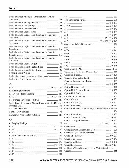
Multi-Function Analog 1 (Terminal AM Monitor Selection) . . . . . . . . . . . . . . . . . . . . . . . . . . . . . . . . . . . . . . . . 223Multi-Function Analog Outputs . . . . . . . . . . . . . . . . . . . . 105Multi-Function Contact Input . . . . . . . . . . . . . . . . . . . . . . . .98Multi-Function Contact Output . . . . . . . . . . . . . . . . . . . . 105Multi-Function Digital Inputs . . . . . . . . . . . . . . . . . . . . . . . .53Multi-Function Digital Input Terminal S1 Function Selection . . . . . . . . . . . . . . . . . . . . . . . . . . . . . . . . . . . . . . . . . 219Multi-Function Digital Input Terminal S2 Function Selection . . . . . . . . . . . . . . . . . . . . . . . . . . . . . . . . . . . . . . . . . 219Multi-Function Digital Input Terminal S3 Function Selection . . . . . . . . . . . . . . . . . . . . . . . . . . . . . . . . . . . . . . . . . 219Multi-Function Digital Input Terminal S4 Function Selection . . . . . . . . . . . . . . . . . . . . . . . . . . . . . . . . . . . . . . . . . 219Multi-Function Digital Input Terminal S5 Function Selection . . . . . . . . . . . . . . . . . . . . . . . . . . . . . . . . . . . . . . . . . 219Multi-Function Digital Output . . . . . . . . . . . . . . . . . . . . . . .54Multi-Function Input Selection Error . . . . . . . . . . . . . . . 145Multi-Function Input Setting Error . . . . . . . . . . . . . . . . . 129Multiple Drive Wiring . . . . . . . . . . . . . . . . . . . . . . . . . . . . . .50Multi-Step Speed Operation (4-Step Speed). . . . . . . . . . .97Multi-Step Speed Reference . . . . . . . . . . . . . . . . . . . . . . . 220
Nn1-02 . . . . . . . . . . . . . . . . . . . . . . . . . . . . . . . . . . . 125, 138, 229n1 Hunting Prevention . . . . . . . . . . . . . . . . . . . . . . . . . . . . 229n3: Overexcitation Braking . . . . . . . . . . . . . . . . . . . . . . . . 229n3-13 . . . . . . . . . . . . . . . . . . . . . . . . . . . . . . . . . . . 134, 136, 229n Advanced Performance Set Up . . . . . . . . . . . . . . . . . . . 229Noise From the Drive or Output Lines When the Drive is Powered On . . . . . . . . . . . . . . . . . . . . . . . . . . . . . . . . . . . . . . 154No-Load Operation . . . . . . . . . . . . . . . . . . . . . . . . . . . . . . . 114Normal Duty Ratings . . . . . . . . . . . . . . . . . . . . . . . . . . . . . 198Number of Auto Restart Attempts . . . . . . . . . . . . . . . . . . 227
Oo1 Display Settings . . . . . . . . . . . . . . . . . . . . . . . . . . . . . . . 229o2-02 . . . . . . . . . . . . . . . . . . . . . . . . . . . . . . . . . . . . . . . . 151, 229o2-04 . . . . . . . . . . . . . . . . . . . . . . . . . . . . . . . . . . . . . . . . 145, 230o2-05 . . . . . . . . . . . . . . . . . . . . . . . . . . . . . . . . . . . . . . . . . . . . 230o2 Multi-Function Selections . . . . . . . . . . . . . . . . . . . . . . 229o4-01 . . . . . . . . . . . . . . . . . . . . . . . . . . . . . . . . . . . . . . . . . . . . 230o4-02 . . . . . . . . . . . . . . . . . . . . . . . . . . . . . . . . . . . . . . . . . . . . 230o4-03 . . . . . . . . . . . . . . . . . . . . . . . . . . . . . . . . . . . . . . . . 142, 231o4-05 . . . . . . . . . . . . . . . . . . . . . . . . . . . . . . . . . . . . . . . . . . . . 231o4-07 . . . . . . . . . . . . . . . . . . . . . . . . . . . . . . . . . . . . . . . . . . . . 231o4-09 . . . . . . . . . . . . . . . . . . . . . . . . . . . . . . . . . . . . . . . . . . . . 231
o4-11 . . . . . . . . . . . . . . . . . . . . . . . . . . . . . . . . . . . . . . . . . . . . 231o4 Maintenance Period . . . . . . . . . . . . . . . . . . . . . . . . . . . . 230oC. . . . . . . . . . . . . . . . . . . . . . . . . . . . . . . . . . . . . . . . . . . 128, 133oFA01 . . . . . . . . . . . . . . . . . . . . . . . . . . . . . . . . . . . . . . . 128, 134oH. . . . . . . . . . . . . . . . . . . . . . . . . . . . . . . . . . . . . . . . . . . 129, 142oH1 . . . . . . . . . . . . . . . . . . . . . . . . . . . . . . . . . . . . . . . . . 128, 135oL1. . . . . . . . . . . . . . . . . . . . . . . . . . . . . . . . . . . . . . . . . . 128, 135oL2. . . . . . . . . . . . . . . . . . . . . . . . . . . . . . . . . . . . . 128, 136, 156oL3. . . . . . . . . . . . . . . . . . . . . . . . . . . . . . . . 128, 129, 136, 143o Operator Related Parameters . . . . . . . . . . . . . . . . . . . . . 229oPE. . . . . . . . . . . . . . . . . . . . . . . . . . . . . . . . . . . . . . . . . . . . . . 145oPE01 . . . . . . . . . . . . . . . . . . . . . . . . . . . . . . . . . . . . . . . 129, 145oPE02 . . . . . . . . . . . . . . . . . . . . . . . . . . . . . . . . . . . . . . . 129, 145oPE03 . . . . . . . . . . . . . . . . . . . . . . . . . . . . . . . . . . . . . . . 129, 145oPE05 . . . . . . . . . . . . . . . . . . . . . . . . . . . . . . . . . . . . . . . 129, 146oPE10 . . . . . . . . . . . . . . . . . . . . . . . . . . . . . . . . . . . . . . . 129, 146oPE11 . . . . . . . . . . . . . . . . . . . . . . . . . . . . . . . . . . . . . . . 129, 146Open-Chassis IP20. . . . . . . . . . . . . . . . . . . . . . . . . . . . . . 32, 33Operating with the Load Connected . . . . . . . . . . . . . . . . 116Operation Errors . . . . . . . . . . . . . . . . . . . . . . . . . . . . . . 127, 129Operator Connection Fault . . . . . . . . . . . . . . . . . . . . . . . . 128Operator Programming Errors . . . . . . . . . . . . . . . . . . . . . 145oPr . . . . . . . . . . . . . . . . . . . . . . . . . . . . . . . . . . . . . . . . . . 128, 137Option Disconnected. . . . . . . . . . . . . . . . . . . . . . . . . . . . . . 128Option Unit External Fault . . . . . . . . . . . . . . . . . . . . 128, 132Option Unit Fault . . . . . . . . . . . . . . . . . . . . . . . . . . . . . . . . . 134Oscillation or Hunting. . . . . . . . . . . . . . . . . . . . . . . . . . . . . 155Output Current . . . . . . . . . . . . . . . . . . . . . . . . . . . . . . . 110, 231Output Current (A) . . . . . . . . . . . . . . . . . . . . . . . . . . . 199, 201Output Frequency. . . . . . . . . . . . . . . . . . . . . . . . . . . . . 110, 231Output Frequency is not as High as Frequency Reference. . . . . . . . . . . . . . . . . . . . . . . . . . . . . . . . . . . . . . . . . . . . . . . . . . 156Output Phase Loss . . . . . . . . . . . . . . . . . . . . . . . . . . . . 128, 133Output Terminal Status. . . . . . . . . . . . . . . . . . . . . . . . 110, 232Output Voltage Reference . . . . . . . . . . . . . . . . . . . . . 110, 231ov . . . . . . . . . . . . . . . . . . . . . . . . . . . . . . . . . 128, 129, 137, 143Overcurrent . . . . . . . . . . . . . . . . . . . . . . . . . . . . . . . . . . 128, 133Overexcitation Deceleration Gain . . . . . . . . . . . . . . 134, 229Overheat 1 (Heatsink Overheat). . . . . . . . . . . . . . . . . . . . 135Overload Tolerance . . . . . . . . . . . . . . . . . . . . . . . . . . . 199, 201Overtorque 1 . . . . . . . . . . . . . . . . . . . . . . . . . . . . . . . . . 129, 143Overtorque Detection 1 . . . . . . . . . . . . . . . . . . . . . . . 128, 136Overvoltage . . . . . . . . . . . . . . . . . . . . . . . . . . . . . 128, 129, 137ov Occurs When Starting a Fan or Motor Speed Loss Occurs . . . . . . . . . . . . . . . . . . . . . . . . . . . . . . . . . . . . . . . . . . . 155
Index
260 YASKAWA ELECTRIC TOEP C710606 26B YASKAWA AC Drive – J1000 Quick Start Guide
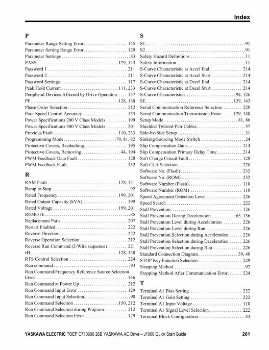
PParameter Range Setting Error . . . . . . . . . . . . . . . . . . . . . 145Parameter Setting Range Error . . . . . . . . . . . . . . . . . . . . . 129Parameter Settings . . . . . . . . . . . . . . . . . . . . . . . . . . . . . . . . . .83PASS . . . . . . . . . . . . . . . . . . . . . . . . . . . . . . . . . . . . . . . . 129, 143Password 1 . . . . . . . . . . . . . . . . . . . . . . . . . . . . . . . . . . . . . . . 211Password 2 . . . . . . . . . . . . . . . . . . . . . . . . . . . . . . . . . . . . . . . 211Password Settings . . . . . . . . . . . . . . . . . . . . . . . . . . . . . . . . 117Peak Hold Current . . . . . . . . . . . . . . . . . . . . . . . . . . . . 111, 233Peripheral Devices Affected by Drive Operation . . . . 157PF . . . . . . . . . . . . . . . . . . . . . . . . . . . . . . . . . . . . . . . . . . . 128, 138Phase Order Selection . . . . . . . . . . . . . . . . . . . . . . . . . . . . . 212Poor Speed Control Accuracy. . . . . . . . . . . . . . . . . . . . . . 153Power Specifications 200 V Class Models . . . . . . . . . . 199Power Specifications 400 V Class Models . . . . . . . . . . 201Previous Fault . . . . . . . . . . . . . . . . . . . . . . . . . . . . . . . . 110, 233Programming Mode. . . . . . . . . . . . . . . . . . . . . . . . . .79, 81, 82Protective Covers, Reattaching. . . . . . . . . . . . . . . . . . . . . 195Protective Covers, Removing . . . . . . . . . . . . . . . . . . . 44, 194PWM Feedback Data Fault . . . . . . . . . . . . . . . . . . . . . . . . 128PWM Feedback Fault . . . . . . . . . . . . . . . . . . . . . . . . . . . . . 132
RRAM Fault . . . . . . . . . . . . . . . . . . . . . . . . . . . . . . . . . . . 128, 131Ramp to Stop. . . . . . . . . . . . . . . . . . . . . . . . . . . . . . . . . . . . . . .92Rated Frequency. . . . . . . . . . . . . . . . . . . . . . . . . . . . . . 199, 201Rated Output Capacity (kVA) . . . . . . . . . . . . . . . . . . . . . 199Rated Voltage . . . . . . . . . . . . . . . . . . . . . . . . . . . . . . . . 199, 201REMOTE . . . . . . . . . . . . . . . . . . . . . . . . . . . . . . . . . . . . . . . . . .85Replacement Parts . . . . . . . . . . . . . . . . . . . . . . . . . . . . . . . . 207Restart Enabled. . . . . . . . . . . . . . . . . . . . . . . . . . . . . . . . . . . 222Reverse Direction. . . . . . . . . . . . . . . . . . . . . . . . . . . . . . . . . 222Reverse Operation Selection . . . . . . . . . . . . . . . . . . . . . . . 212Reverse Run Command (2-Wire sequence) . . . . . . . . . 221rH . . . . . . . . . . . . . . . . . . . . . . . . . . . . . . . . . . . . . . . . . . . 128, 138RTS Control Selection . . . . . . . . . . . . . . . . . . . . . . . . . . . . 224Run command . . . . . . . . . . . . . . . . . . . . . . . . . . . . . . . . . . . . . .93Run Command/Frequency Reference Source Selection Error. . . . . . . . . . . . . . . . . . . . . . . . . . . . . . . . . . . . . . . . . . . . . 146Run Command at Power Up . . . . . . . . . . . . . . . . . . . . . . . 212Run Command Input Error . . . . . . . . . . . . . . . . . . . . . . . . 129Run Command Input Selection. . . . . . . . . . . . . . . . . . . . . . .90Run Command Selection . . . . . . . . . . . . . . . . . . . . . . 150, 212Run Command Selection during Program. . . . . . . . . . . 212Run Command Selection Error. . . . . . . . . . . . . . . . . . . . . 129
SS1 . . . . . . . . . . . . . . . . . . . . . . . . . . . . . . . . . . . . . . . . . . . . . . . . .91S2 . . . . . . . . . . . . . . . . . . . . . . . . . . . . . . . . . . . . . . . . . . . . . . . . .91Safety Hazard Definitions . . . . . . . . . . . . . . . . . . . . . . . . . . .11Safety Information . . . . . . . . . . . . . . . . . . . . . . . . . . . . . . . . . .11S-Curve Characteristic at Accel End. . . . . . . . . . . . . . . . 214S-Curve Characteristic at Accel Start . . . . . . . . . . . . . . . 214S-Curve Characteristic at Decel End. . . . . . . . . . . . . . . . 214S-Curve Characteristic at Decel Start . . . . . . . . . . . . . . . 214S-Curve Characteristics . . . . . . . . . . . . . . . . . . . . . . . . 94, 126SE. . . . . . . . . . . . . . . . . . . . . . . . . . . . . . . . . . . . . . . . . . . 129, 143Serial Communication Reference Selection . . . . . . . . . 220Serial Communication Transmission Error . . . . . . 129, 140Setup Mode . . . . . . . . . . . . . . . . . . . . . . . . . . . . . . . . . . . . 81, 86Shielded Twisted-Pair Cables . . . . . . . . . . . . . . . . . . . . . . . .57Side-by-Side Setup . . . . . . . . . . . . . . . . . . . . . . . . . . . . . . . . .31Sinking/Sourcing Mode Switch . . . . . . . . . . . . . . . . . . . . . .24Slip Compensation Gain. . . . . . . . . . . . . . . . . . . . . . . . . . . 214Slip Compensation Primary Delay Time . . . . . . . . . . . . 214Soft Charge Circuit Fault . . . . . . . . . . . . . . . . . . . . . . . . . . 128Soft CLA Selection . . . . . . . . . . . . . . . . . . . . . . . . . . . . . . . 228Software No. (Flash) . . . . . . . . . . . . . . . . . . . . . . . . . . . . . . 232Software No. (ROM). . . . . . . . . . . . . . . . . . . . . . . . . . . . . . 232Software Number (Flash). . . . . . . . . . . . . . . . . . . . . . . . . . 110Software Number (ROM) . . . . . . . . . . . . . . . . . . . . . . . . . 110Speed Agreement Detection Level . . . . . . . . . . . . . . . . . 226Speed Search . . . . . . . . . . . . . . . . . . . . . . . . . . . . . . . . . . . . . 222Stall Prevention. . . . . . . . . . . . . . . . . . . . . . . . . . . . . . . . . . . 126Stall Prevention During Deceleration . . . . . . . . . . . . 65, 136Stall Prevention Level during Acceleration . . . . . . . . . 226Stall Prevention Level during Run . . . . . . . . . . . . . . . . . 226Stall Prevention Selection during Acceleration . . . . . . 226Stall Prevention Selection during Deceleration . . . . . . 226Stall Prevention Selection during Run . . . . . . . . . . . . . . 226Standard Connection Diagram . . . . . . . . . . . . . . . . . . . 39, 40STOP Key Function Selection . . . . . . . . . . . . . . . . . . . . . 229Stopping Method . . . . . . . . . . . . . . . . . . . . . . . . . . . . . . . . . . .92Stopping Method After Communication Error. . . . . . . 224
TTerminal A1 Bias Setting. . . . . . . . . . . . . . . . . . . . . . . . . . 222Terminal A1 Gain Setting . . . . . . . . . . . . . . . . . . . . . . . . . 222Terminal A1 Input Voltage . . . . . . . . . . . . . . . . . . . . . . . . 110Terminal A1 Signal Level Selection . . . . . . . . . . . . . . . . 222Terminal Block Configuration . . . . . . . . . . . . . . . . . . . . . . .43
Index
YASKAWA ELECTRIC TOEP C710606 26B YASKAWA AC Drive – J1000 Quick Start Guide 261
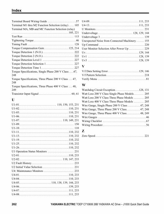
Terminal Board Wiring Guide . . . . . . . . . . . . . . . . . . . . . . .57Terminal M1 thru M2 Function Selection (relay) . . . . 105Terminal MA, MB and MC Function Selection (relay). . . . . . . . . . . . . . . . . . . . . . . . . . . . . . . . . . . . . . . . . . . . . . 105, 221Test Run . . . . . . . . . . . . . . . . . . . . . . . . . . . . . . . . . . . . . . . . . 115Tightening Torque . . . . . . . . . . . . . . . . . . . . . . . . . . . . . . . . . .46Timing Fault . . . . . . . . . . . . . . . . . . . . . . . . . . . . . . . . . . . . . 128Torque Compensation Gain. . . . . . . . . . . . . . . . . . . . 125, 214Torque Detection 1 (N.O.). . . . . . . . . . . . . . . . . . . . . . . . . 222Torque Detection 2 (N.O.). . . . . . . . . . . . . . . . . . . . . . . . . 222Torque Detection Level 1 . . . . . . . . . . . . . . . . . . . . . . . . . 227Torque Detection Selection 1 . . . . . . . . . . . . . . . . . . . . . . 227Torque Detection Time 1 . . . . . . . . . . . . . . . . . . . . . . . . . . 227Torque Specifications, Single Phase 200 V Class . . . .47, 248Torque Specifications, Three Phase 200 V Class . . . 47, 248Torque Specifications, Three Phase 400 V Class . . . 48, 249Transistor Input Signal . . . . . . . . . . . . . . . . . . . . . . . . . . 60, 61
UU1-01. . . . . . . . . . . . . . . . . . . . . . . . . . . . . . 110, 150, 153, 231U1-02. . . . . . . . . . . . . . . . . . . . . . . . . . . . . . . . . . . . . . . . 110, 231U1-03. . . . . . . . . . . . . . . . . . . . . . . . . . . . . . . . . . . . . . . . 110, 231U1-06. . . . . . . . . . . . . . . . . . . . . . . . . . . . . . . . . . . . . . . . 110, 231U1-07. . . . . . . . . . . . . . . . . . . . . . . . . . . . . . . . . . . 110, 149, 231U1-09. . . . . . . . . . . . . . . . . . . . . . . . . . . . . . . . . . . . . . . . . . . . 150U1-10. . . . . . . . . . . . . . . . . . . . . . . . . . . . . . . . . . . . . . . . . . . . 110U1-11. . . . . . . . . . . . . . . . . . . . . . . . . . . . . . . . . . . . . . . . 110, 232U1-13. . . . . . . . . . . . . . . . . . . . . . . . . . . . . . . . . . . . . . . . 110, 232U1-19. . . . . . . . . . . . . . . . . . . . . . . . . . . . . . . . . . . . . . . . 110, 232U1-25. . . . . . . . . . . . . . . . . . . . . . . . . . . . . . . . . . . . . . . . 110, 232U1-26. . . . . . . . . . . . . . . . . . . . . . . . . . . . . . . . . . . . . . . . 110, 232U1 Operation Status Monitors . . . . . . . . . . . . . . . . . . . . . 231U2-01. . . . . . . . . . . . . . . . . . . . . . . . . . . . . . . . . . . . . . . . 110, 233U2-02. . . . . . . . . . . . . . . . . . . . . . . . . . . . . . . . . . . 110, 147, 233U2 Fault History. . . . . . . . . . . . . . . . . . . . . . . . . . . . . . . . . . 233U2 Initial Value Selection . . . . . . . . . . . . . . . . . . . . . . . . . 231U4: Maintenance Monitors . . . . . . . . . . . . . . . . . . . . . . . . 233U4-01. . . . . . . . . . . . . . . . . . . . . . . . . . . . . . . . . . . . . . . . 110, 233U4-04. . . . . . . . . . . . . . . . . . . . . . . . . . . . . . . . . . . . . . . . 110, 233U4-05. . . . . . . . . . . . . . . . . . . . . . . . . . 110, 138, 139, 144, 233U4-06. . . . . . . . . . . . . . . . . . . . . . . . . . . . . . . . . . . . . . . . 139, 233U4-07. . . . . . . . . . . . . . . . . . . . . . . . . . . . . . . . . . . . . . . . 111, 233U4-08. . . . . . . . . . . . . . . . . . . . . . . . . . . . . . . . . . . . . . . . 111, 233
U4-09. . . . . . . . . . . . . . . . . . . . . . . . . . . . . . . . . . . . . . . . 111, 233U4-13. . . . . . . . . . . . . . . . . . . . . . . . . . . . . . . . . . . . . . . . 111, 233U Monitors. . . . . . . . . . . . . . . . . . . . . . . . . . . . . . . . . . . . . . . 231Undervoltage . . . . . . . . . . . . . . . . . . . . . . . . . . . . 128, 129, 144Undervoltage 3 . . . . . . . . . . . . . . . . . . . . . . . . . . . . . . . . . . . 139Unexpected Noise from Connected Machinery . . . . . . 155Up Command . . . . . . . . . . . . . . . . . . . . . . . . . . . . . . . . . . . . 220User Monitor Selection After Power Up . . . . . . . . . . . . 229Uv. . . . . . . . . . . . . . . . . . . . . . . . . . . . . . . . . . . . . . . . . . . 129, 144Uv1 . . . . . . . . . . . . . . . . . . . . . . . . . . . . . . . . . . . . . . . . . 128, 139Uv3 . . . . . . . . . . . . . . . . . . . . . . . . . . . . . . . . . . . . . . . . . 128, 139
VV/f Data Setting Error. . . . . . . . . . . . . . . . . . . . . . . . . 129, 146V/f Pattern Selection . . . . . . . . . . . . . . . . . . . . . . . . . . . . . . 218Verify Menu . . . . . . . . . . . . . . . . . . . . . . . . . . . . . . . . . . . . . . .81
WWatchdog Circuit Exception . . . . . . . . . . . . . . . . . . . 128, 131Watt Loss 200 V Class Single Phase Models . . . . . . . . 205Watt Loss 200 V Class Three Phase Models . . . . . . . . 205Watt Loss 400 V Class Three Phase Models . . . . . . . . 205Wire Gauge, Single Phase 200 V Class . . . . . . . . . . 47, 248Wire Gauge, Three Phase 200 V Class. . . . . . . . . . . 47, 248Wire Gauge, Three Phase 400 V Class. . . . . . . . . . . 48, 249Wire Gauges . . . . . . . . . . . . . . . . . . . . . . . . . . . . . . . . . . . . . . .46Wiring Checklist . . . . . . . . . . . . . . . . . . . . . . . . . . . . . . . . . . .67Wiring Procedure . . . . . . . . . . . . . . . . . . . . . . . . . . . . . . . . . . .56
ZZero Speed . . . . . . . . . . . . . . . . . . . . . . . . . . . . . . . . . . . . . . . 221
Index
262 YASKAWA ELECTRIC TOEP C710606 26B YASKAWA AC Drive – J1000 Quick Start Guide
Revision HistoryThe revision dates and the numbers of the revised manuals appear on the bottom of the back cover.
Date ofPublication
RevisionNumber Section Revised Content
December 2011 2
Cover Revision: Format
All Revision: Reviewed and corrected entiredocumentation
Chapter 3Chapter 7
Revision: Precautions on installing a leakagebreakerRevision: Wire Gauge and Torque Specifications
Appendix CRevision: Wire Gauge and Torque SpecificationsRevision: Closed-Loop Crimp Terminal SizeRevision: Fuse list
Back Cover Revision: Format and address
July 2009 1 Back Cover Revision: Address
February 2008 - - First Edition
YASKAWA AMERICA, INC.2121 Norman Drive South, Waukegan, IL 60085, U.S.A.Phone: (800) YASKAWA (927-5292) or 1-847-887-7000 Fax: 1-847-887-7310http://www.yaskawa.com
DRIVE CENTER (INVERTER PLANT)2-13-1, Nishimiyaichi, Yukuhashi, Fukuoka, 824-8511, JapanPhone: 81-930-25-3844 Fax: 81-930-25-4369http://www.yaskawa.co.jp
YASKAWA ELECTRIC CORPORATIONNew Pier Takeshiba South Tower, 1-16-1, Kaigan, Minatoku, Tokyo, 105-6891, JapanPhone: 81-3-5402-4502 Fax: 81-3-5402-4580http://www.yaskawa.co.jp
YASKAWA ELÉTRICO DO BRASIL LTDA.Avenda Fagundes Filho, 620 Bairro Saude, São Paulo, SP04304-000, BrasilPhone: 55-11-3585-1100 Fax: 55-11-5581-8795http://www.yaskawa.com.br
YASKAWA EUROPE GmbHHauptstrasse 185, 65760 Eschborn, GermanyPhone: 49-6196-569-300 Fax: 49-6196-569-398http://www.yaskawa.eu.com
YASKAWA ELECTRIC UK LTD.1 Hunt Hill Orchardton Woods, Cumbernauld, G68 9LF, United KingdomPhone: 44-1236-735000 Fax: 44-1236-458182http://www.yaskawa.co.uk
YASKAWA ELECTRIC KOREA CORPORATION9F, Kyobo Securities Bldg., 26-4, Yeouido-dong, Yeongdeungpo-gu, Seoul, 150-737, KoreaPhone: 82-2-784-7844 Fax: 82-2-784-8495http://www.yaskawa.co.kr
YASKAWA ELECTRIC (SINGAPORE) PTE. LTD.151 Lorong Chuan, #04-01, New Tech Park, 556741, SingaporePhone: 65-6282-3003 Fax: 65-6289-3003http://www.yaskawa.com.sg
YASKAWA ELECTRIC (SHANGHAI) CO., LTD.12F, Carlton Bld., No.21 HuangHe Road, HuangPu District, Shanghai 200003, ChinaPhone: 86-21-5385-2200 Fax: 86-21-5385-3299http://www.yaskawa.com.cn
YASKAWA ELECTRIC (SHANGHAI) CO., LTD. BEIJING OFFICERoom 1011, Tower W3 Oriental Plaza, No. 1 East Chang An Ave., Dong Cheng District, Beijing, 100738, ChinaPhone: 86-10-8518-4086 Fax: 86-10-8518-4082
YASKAWA ELECTRIC TAIWAN CORPORATION9F, 16, Nanking E. Rd., Sec. 3, Taipei, 104, TaiwanPhone: 886-2-2502-5003 Fax: 886-2-2505-1280
YASKAWA ELECTRIC INDIA PRIVATE LIMITED#17/A Electronics City, Hosur Road Bangalore 560 100 (Karnataka), IndiaPhone: 91-80-4244-1900 Fax: 91-80-4244-1901http://www.yaskawaindia.in
Published in Japan December 2011 08-2
MANUAL NO. TOEP C710606 26B
11-12-8_YAI
In the event that the end user of this product is to be the military and said product is to be employed in any weapons systems or the manufacture thereof, the export will fall under the relevant regulations as stipulated in the Foreign Exchange and Foreign Trade Regulations. Therefore, be sure to follow all procedures and submit all relevant documentation according to any and all rules, regulations and laws that may apply.
Specifications are subject to change without notice for ongoing product modifications and improvements.
© 2008-2011 YASKAWA ELECTRIC CORPORATION. All rights reserved.
2
YASKAWA ELECTRIC CORPORATION
YASKAWA AC Drive-J1000Compact V/f Control Drive
Quick Start Guide
Recommended