Embed Size (px)
Citation preview
Reliable and Smart
J1000200 V CLASS, THREE-PHASE INPUT: 0.1 to 5.5 kW200 V CLASS, SINGLE-PHASE INPUT: 0.1 to 2.2 kW400 V CLASS, THREE-PHASE INPUT: 0.2 to 5.5 kW
YASKAWA
Certified forISO9001 andISO14001
ENVIRONMENTALSYSTEM
C
ERT I F I ED
MA
N
AGEMENT SYSTEM
JQA-EM0498JQA-0422
QUALITY SYSTEM
C
ERT I F I ED
MA
N
AGEMENT SYSTEM
Compact V/f Control DriveYASKAWA AC Drive
RoHScompliant
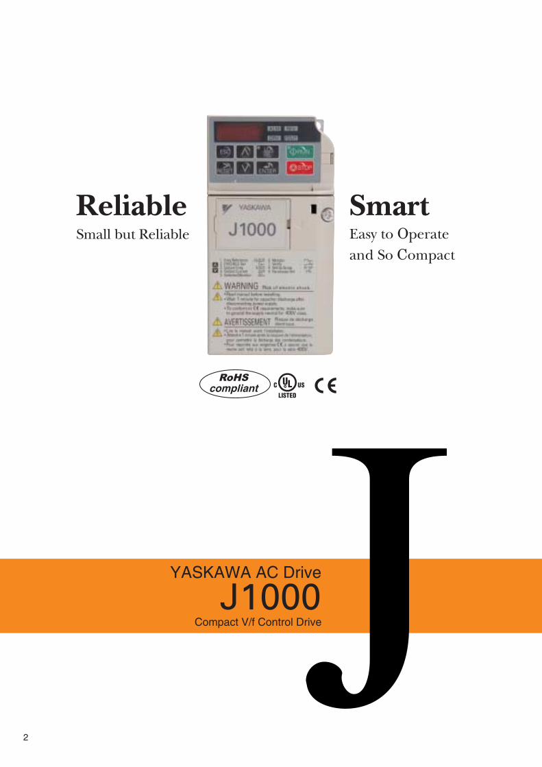
Small but Reliable
Reliable SmartEasy to Operateand So Compact
J1000Compact V/f Control Drive
YASKAWA AC Drive
2

FeaturesApplication BenefitsSoftware FunctionsParameter ListBasic InstructionsProduct LineupModel SelectionStandard SpecificationsStandard Connection DiagramDimensionsDrive Watts Loss DataPeripheral Devices and OptionsApplication NotesYASKAWA AC Drive SeriesGlobal Service Network
48
10121416171820222426475153
Reliability the world has come to expect
from Yaskawa as a global leader is now
packed into an even smaller, more
powerful unit.
So easy to use: just switch it on and
you're ready to go.
J1000 is fu l ly capable of ef f ic ient
per fo rmance and energy sav ing ,
handl ing var iable speed needs in
compact applications.
A drive that exemplif ies true world
quality with a difference you can really
feel.
CONTENTS
3
50025
0
350
1180
800
595
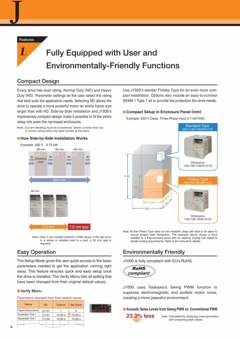
Compact Design
Every drive has dual rating, Normal Duty (ND) and Heavy Duty (HD). Parameter settings let the user select the rating that best suits the application needs. Selecting ND allows the drive to operate a more powerful motor an entire frame size larger than with HD. Side-by-Side installation and J1000's impressively compact design make it possible to fit the entire setup into even the narrowest enclosures.
Easy Operation
The Setup Mode gives the user quick access to the basic parameters needed to get the application running right away. This feature ensures quick and easy setup once the drive is installed. The Verify Menu lists all setting that have been changed from their original default values.
Environmentally Friendly
J1000 is fully compliant with EU's RoHS.
J1000 uses Yaskawa's Swing PWM function to suppress electromagnetic and audible motor noise, creating a more peaceful environment.
Use J1000's slender Finless Type for an even more com-pact installation. Options also include an easy-to-connect NEMA 1 Type 1 kit to provide the protection the drive needs.
Compact Setup in Enclosure Panel (mm)
How Side-by-Side Installation Works
Verify Menu
Acoustic Noise Levels from Swing PWM vs. Conventional PWM
112 mm less!
68 mm
Example: 200 V 0.75 kW
(Conventional model)
J730mm
68 mm
J730mm
68 mm
J730mm
30mm
212 mm
324 mm
68 mm
Note: Only 2 mm needed between J1000 drives. If the last drive in a series is installed next to a wall, a 30 mm gap is required.
Note: Calculated by analyzing noise generation and comparing peak values.
Note: Current derating must be considered. Select a motor that has a current rating within the rated current of the drive.
Note: As the Finless Type lacks its own heatsink, steps still need to be taken to ensure proper heat dissipation. The example above shows a drive installed to a fully-enclosed panel with an external cooling unit added to handle cooling requirements. Refer to the manual for details.
Parameters changed from their default values
No.
b1-01
C1-01
C1-02
Default
110.00 s
10.00 s
Set Value
015.00 s
15.00 s
Name
Frequency Reference Selection
Acceleration Time 1
Deceleration Time 1
Example: 200 V Class, Three-Phase Input 3.7 kW (HD)
Fully Equipped with User and
Environmentally-Friendly Functions
Features
1.
23.3% less
Standard Type 800×1180×350(W×H×D)
Dimensions140×128×148(W×H×D)
Finless Type500×595×250(W×H×D)
Dimensions140×128×78(W×H×D)
RoHScompliant
4
J1000Compact V/f Control Drive
YASKAWA AC Drive
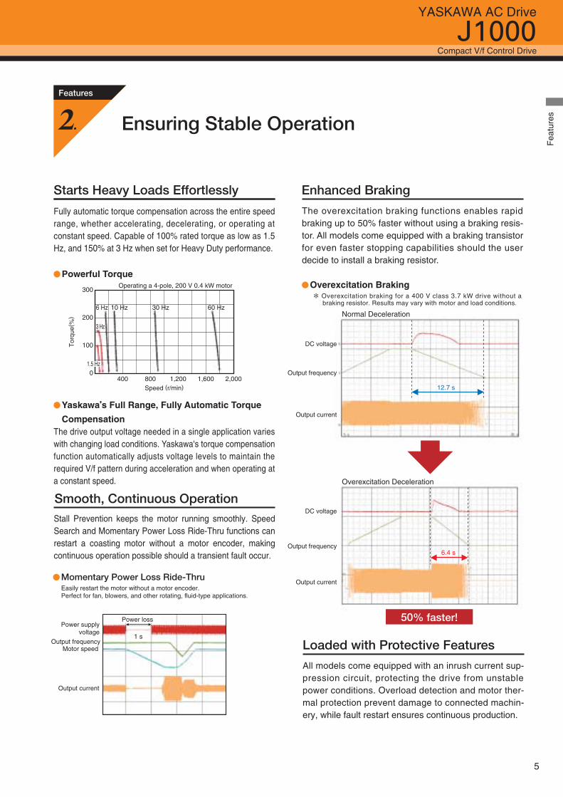
Enhanced Braking
Loaded with Protective Features
All models come equipped with an inrush current sup-pression circuit, protecting the drive from unstable power conditions. Overload detection and motor ther-mal protection prevent damage to connected machin-ery, while fault restart ensures continuous production.
12.7 s
6.4 s
50% faster!
Normal Deceleration
Overexcitation Deceleration
DC voltage
DC voltage
Output frequency
Output frequency
Output current
Output current
Smooth, Continuous Operation
The overexcitation braking functions enables rapid braking up to 50% faster without using a braking resis-tor. All models come equipped with a braking transistor for even faster stopping capabilities should the user decide to install a braking resistor.
Powerful Torque
Yaskawa’s Full Range, Fully Automatic Torque
Compensation
Overexcitation BrakingOperating a 4-pole, 200 V 0.4 kW motor
* Overexcitation braking for a 400 V class 3.7 kW drive without a braking resistor. Results may vary with motor and load conditions.
400 800 1,200 1,600 2,000
Tor
que(
%)
Speed (r/min)
3 Hz
6 Hz 30 Hz10 Hz 60 Hz
0
100
200
300
1.5 Hz
Starts Heavy Loads Effortlessly
Fully automatic torque compensation across the entire speed range, whether accelerating, decelerating, or operating at constant speed. Capable of 100% rated torque as low as 1.5 Hz, and 150% at 3 Hz when set for Heavy Duty performance.
The drive output voltage needed in a single application varies with changing load conditions. Yaskawa's torque compensation function automatically adjusts voltage levels to maintain the required V/f pattern during acceleration and when operating at a constant speed.
Ensuring Stable Operation
Features
2.
Stall Prevention keeps the motor running smoothly. Speed Search and Momentary Power Loss Ride-Thru functions can restart a coasting motor without a motor encoder, making continuous operation possible should a transient fault occur.
Easily restart the motor without a motor encoder.Perfect for fan, blowers, and other rotating, fluid-type applications.
Momentary Power Loss Ride-Thru
Power loss
1 s
Power supplyvoltage
Motor speedOutput frequency
Output current
Fea
ture
s
5
Features
3.
Model Transition
DriveWizard Plus
True Reliability and Top Quality Assurance
Hassle-Free Maintenance Convenient Parameter Management
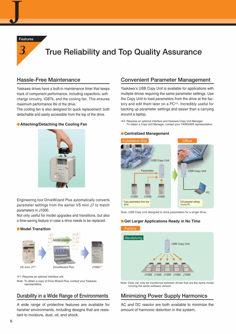
Yaskawa drives have a built-in maintenance timer that keeps track of component performance, including capacitors, soft-charge circuitry, IGBTs, and the cooling fan. This ensures maximum performance life of the drive.The cooling fan is also designed for quick replacement: both detachable and easily accessible from the top of the drive.
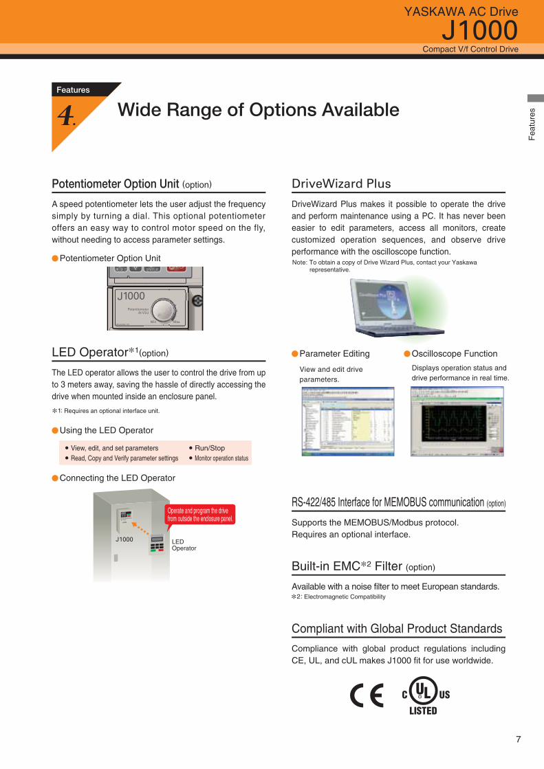
Centralized Management
Attaching/Detaching the Cooling Fan
Engineering tool DriveWizard Plus automatically converts parameter settings from the earlier VS mini J7 to match parameters in J1000.Not only useful for model upgrades and transitions, but also a time-saving feature in case a drive needs to be replaced.
Yaskawa’s USB Copy Unit is available for applications with multiple drives requiring the same parameter settings. Use the Copy Unit to load parameters from the drive at the fac-tory and edit them later on a PC*2. Incredibly useful for backing up parameter settings and easier than a carrying around a laptop.
Durability in a Wide Range of Environments
A wide range of protective features are available for harsher environments, including designs that are resis-tant to moisture, dust, oil, and shock.
Minimizing Power Supply Harmonics
AC and DC reactor are both available to minimize the amount of harmonic distortion in the system.
Automatic conversion
Get Larger Applications Ready in No Time
Installation Site Office
Parameter
J1000 J1000J1000
Copy parameters from any drive
PC
Edit parameter settings on your PC
USB Copy Unit
J1000 J1000 J1000J1000J1000
USB Copy Unit
USB Copy Unit
J1000J1000J1000J1000 J1000
*1: Requires an optional interface unit.
*2: Requires an optional interface and freeware Copy Unit Manager.To obtain a Copy Unit Manager, contact your YASKAWA representative.
VS mini J7*1 J1000*1
Factory
Manufacturing
Note: USB Copy Unit designed to store parameters for a single drive.
Note: Data can only be transferred between drives that are the same model running the same software version.
Note: To obtain a copy of Drive Wizard Plus, contact your Yaskawa representative.
6
J1000Compact V/f Control Drive
YASKAWA AC Drive
Features
4.Wide Range of Options Available
Potentiometer Option Unit
Potentiometer Option Unit (option)
A speed potentiometer lets the user adjust the frequency simply by turning a dial. This optional potentiometer offers an easy way to control motor speed on the fly, without needing to access parameter settings.
Using the LED Operator
Connecting the LED Operator
LED Operator*1(option)
The LED operator allows the user to control the drive from up to 3 meters away, saving the hassle of directly accessing the drive when mounted inside an enclosure panel.
DriveWizard Plus
DriveWizard Plus makes it possible to operate the drive and perform maintenance using a PC. It has never been easier to edit parameters, access all monitors, create customized operation sequences, and observe drive performance with the oscilloscope function.
View, edit, and set parametersRead, Copy and Verify parameter settings
Parameter Editing
Run/StopMonitor operation status
RS-422/485 Interface for MEMOBUS communication (option)
Supports the MEMOBUS/Modbus protocol. Requires an optional interface.
Built-in EMC*2 Filter (option)
Available with a noise filter to meet European standards.
Compliant with Global Product Standards
Compliance with global product regulations including CE, UL, and cUL makes J1000 fit for use worldwide.
View and edit drive parameters.
Oscilloscope Function
Displays operation status and drive performance in real time.
J1000
Operate and program the drive from outside the enclosure panel.
J1000 LEDOperator
Note: To obtain a copy of Drive Wizard Plus, contact your Yaskawa representative.
*1: Requires an optional interface unit.
*2: Electromagnetic Compatibility
Fea
ture
s
7
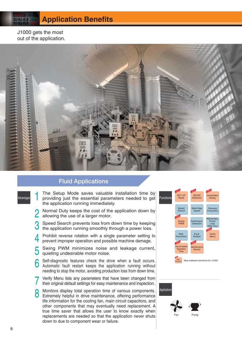
Fluid Applications
1
23456
78
Advantages Functions
Applications
Fan Pump
ReversePrevention
Momentary Power Loss
Ride-Thru
Multi-StepSpeed
Speed Search
SET UPMode
Overtorque Detection
Stall Prevention
Fault Restart
New software functions for J1000New
Functions
SwingPWM
AccumulatedOperation
Time
MaintenanceMonitor
ND/HDSelection
OverexcitationBraking
The Setup Mode saves valuable installation time by providing just the essential parameters needed to get the application running immediately.
Normal Duty keeps the cost of the application down by allowing the use of a larger motor.
Speed Search prevents loss from down time by keeping the application running smoothly through a power loss.
Prohibit reverse rotation with a single parameter setting to prevent improper operation and possible machine damage.
Swing PWM minimizes noise and leakage current, quieting undesirable motor noise.
Self-diagnostic features check the drive when a fault occurs. Automatic fault restart keeps the application running without needing to stop the motor, avoiding production loss from down time.
Verify Menu lists any parameters that have been changed from their original default settings for easy maintenance and inspection.
Monitors display total operation time of various components. Extremely helpful in drive maintenance, offering performance life information for the cooling fan, main circuit capacitors, and other components that may eventually need replacement. A true time saver that allows the user to know exactly when replacements are needed so that the application never shuts down to due to component wear or failure.
VerifyMenu
J1000 gets the most out of the application.
8
Application Benefi ts
ND/HDSelection
OverexcitationBraking
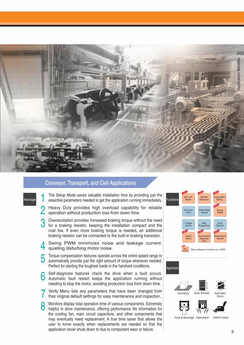
Conveyor, Transport, and Civil Applications
123
45
6
78
Advantages Functions
Applications
Conveyor Auto Shutter AutomaticDoors
TorqueBoost
Stall Prevention
Fault Restart
S-CurveTime
Multi-StepSpeed
New software functions for J1000New Functions
SET UP Mode
AccumulatedOperation
Time
VerifyMenu
MaintenanceMonitor
The Setup Mode saves valuable installation time by providing just the essential parameters needed to get the application running immediately.
Heavy Duty provides high overload capability for reliable operation without production loss from down time.
Overexcitation provides increased braking torque without the need for a braking resistor, keeping the installation compact and the cost low. If even more braking torque is needed, an additional braking resistor can be connected to the built-in braking transistor.
Swing PWM minimizes noise and leakage current, quieting disturbing motor noise.
Torque compensation features operate across the entire speed range to automatically provide just the right amount of torque whenever needed. Perfect for starting the toughest loads in the harshest conditions.
Self-diagnosis features check the drive when a fault occurs. Automatic fault restart keeps the application running without needing to stop the motor, avoiding production loss from down time.
Verify Menu lists any parameters that have been changed from their original default settings for easy maintenance and inspection.
Monitors display total operation time of various components. Extremely helpful in drive maintenance, offering performance life information for the cooling fan, main circuit capacitors, and other components that may eventually need replacement. A true time saver that allows the user to know exactly when replacements are needed so that the application never shuts down to due to component wear or failure.
SwingPWM
Food & Beverage Agricultural Health & Leisure
App
licat
ion
Ben
efits
9
10
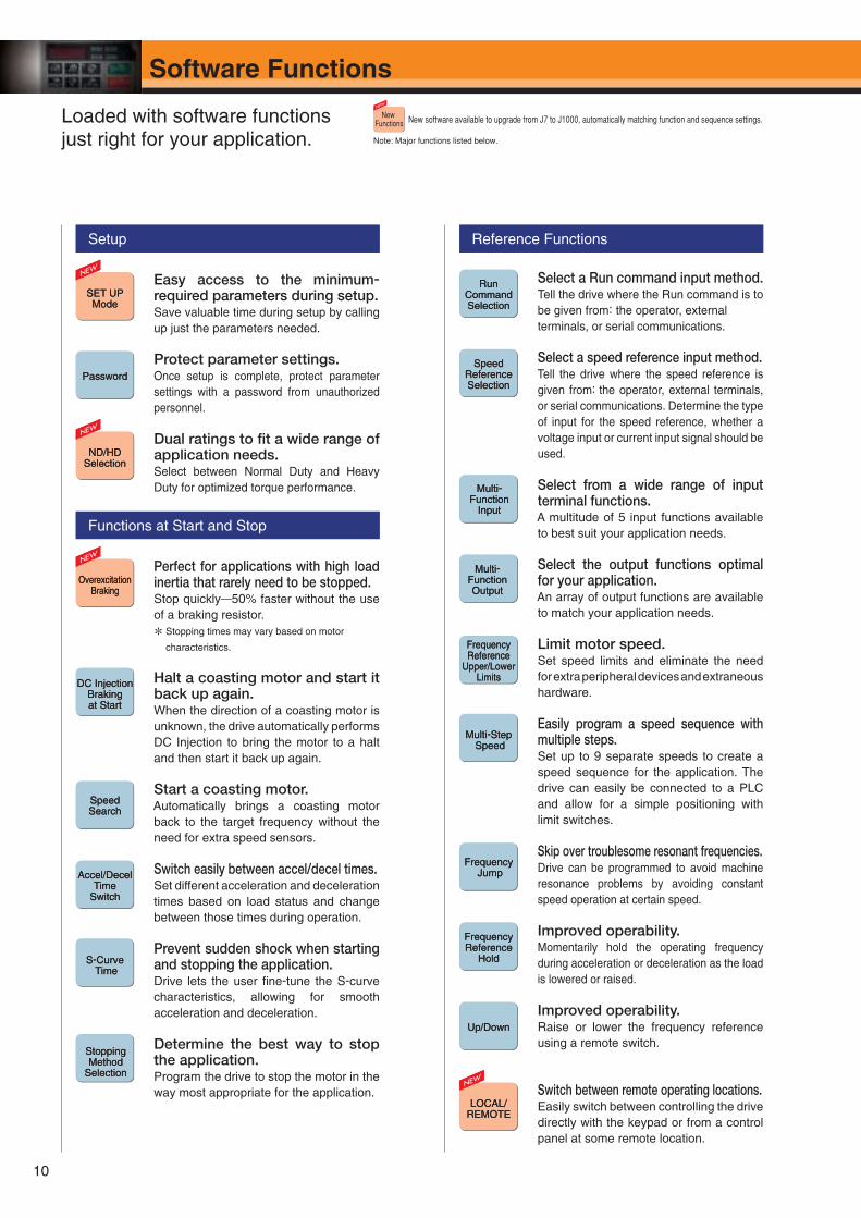
Easy access to the minimum-required parameters during setup.Save valuable time during setup by calling up just the parameters needed.
Protect parameter settings.Once setup is complete, protect parameter settings with a password from unauthorized personnel.
Dual ratings to fi t a wide range of application needs.Select between Normal Duty and Heavy Duty for optimized torque performance.
Perfect for applications with high load inertia that rarely need to be stopped.Stop quickly50% faster without the use of a braking resistor.
* Stopping times may vary based on motor
characteristics.
Halt a coasting motor and start it back up again.When the direction of a coasting motor is unknown, the drive automatically performs DC Injection to bring the motor to a halt and then start it back up again.
Start a coasting motor.Automatically brings a coasting motor back to the target frequency without the need for extra speed sensors.
Switch easily between accel/decel times.Set different acceleration and deceleration times based on load status and change between those times during operation.
Prevent sudden shock when starting and stopping the application.Drive lets the user fi ne-tune the S-curve characteristics, allowing for smooth acceleration and deceleration.
Determine the best way to stop the application. Program the drive to stop the motor in the way most appropriate for the application.
SetupSetup
SET UPMode
SET UPMode
PasswordPassword
ND/HDSelectionND/HD
Selection
Functions at Start and StopFunctions at Start and Stop
Overexcitation Braking
Overexcitation Braking
DC Injection Braking at Start
DC Injection Braking at Start
Speed SearchSpeed Search
Accel/Decel Time
Switch
Accel/Decel Time
Switch
S-Curve Time
S-Curve Time
Stopping Method
Selection
Stopping Method
Selection
Select a Run command input method. Tell the drive where the Run command is to be given from: the operator, external terminals, or serial communications.
Select a speed reference input method.Tell the drive where the speed reference is given from: the operator, external terminals, or serial communications. Determine the type of input for the speed reference, whether a voltage input or current input signal should be used.
Select from a wide range of input terminal functions.A multitude of 5 input functions available to best suit your application needs.
Select the output functions optimal for your application.An array of output functions are available to match your application needs.
Limit motor speed.Set speed limits and eliminate the need for extra peripheral devices and extraneous hardware.
Easily program a speed sequence with multiple steps.Set up to 9 separate speeds to create a speed sequence for the application. The drive can easily be connected to a PLC and allow for a simple positioning with limit switches.
Skip over troublesome resonant frequencies.Drive can be programmed to avoid machine resonance problems by avoiding constant speed operation at certain speed.
Improved operability.Momentarily hold the operating frequency during acceleration or deceleration as the load is lowered or raised.
Improved operability.Raise or lower the frequency reference using a remote switch.
Switch between remote operating locations.Easily switch between controlling the drive directly with the keypad or from a control panel at some remote location.
Reference FunctionsReference Functions
Run Command Selection
Run Command Selection
Speed Reference Selection
Speed Reference Selection
Multi-Function
Input
Multi-Function
Input
Multi-Function Output
Multi-Function Output
Frequency Reference
Upper/Lower Limits
Frequency Reference
Upper/Lower Limits
Multi-Step Speed
Multi-Step Speed
Frequency Jump
Frequency Jump
Frequency Reference
Hold
Frequency Reference
Hold
Up/DownUp/Down
LOCAL/REMOTELOCAL/
REMOTE
Loaded with software functions just right for your application.
Software Functions
New software available to upgrade from J7 to J1000, automatically matching function and sequence settings.New Functions
Note: Major functions listed below.
Sof
twar
e F
unct
ions
11
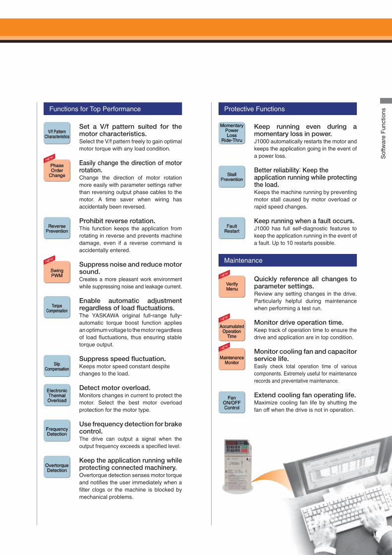
Set a V/f pattern suited for the motor characteristics. Select the V/f pattern freely to gain optimal motor torque with any load condition.
Easily change the direction of motor rotation.Change the direction of motor rotation more easily with parameter settings rather than reversing output phase cables to the motor. A time saver when wiring has accidentally been reversed.
Prohibit reverse rotation.This function keeps the application from rotating in reverse and prevents machine damage, even if a reverse command is accidentally entered.
Suppress noise and reduce motor sound.Creates a more pleasant work environment while suppressing noise and leakage current.
Enable automatic adjustment regardless of load fl uctuations.The YASKAWA original full-range fully-automatic torque boost function applies an optimum voltage to the motor regardless of load fl uctuations, thus ensuring stable torque output.
Suppress speed fl uctuation.Keeps motor speed constant despite changes to the load.
Detect motor overload.Monitors changes in current to protect the motor. Select the best motor overload protection for the motor type.
Use frequency detection for brake control.The drive can output a signal when the output frequency exceeds a specifi ed level.
Keep the application running while protecting connected machinery.Overtorque detection senses motor torque and notifi es the user immediately when a fi lter clogs or the machine is blocked by mechanical problems.
Functions for Top PerformanceFunctions for Top Performance
V/f Pattern Characteristics
V/f Pattern Characteristics
Phase Order
Change
Phase Order
Change
Reverse PreventionReverse
Prevention
Swing PWMSwing PWM
Torque Compensation
Torque Compensation
Slip Compensation
Slip Compensation
Electronic Thermal Overload
Electronic Thermal Overload
Frequency DetectionFrequency Detection
Overtorque Detection
Overtorque Detection
Keep running even during a momentary loss in power.J1000 automatically restarts the motor and keeps the application going in the event of a power loss.
Better reliability: Keep the application running while protecting the load.Keeps the machine running by preventing motor stall caused by motor overload or rapid speed changes.
Keep running when a fault occurs.J1000 has full self-diagnostic features to keep the application running in the event of a fault. Up to 10 restarts possible.
Quickly reference all changes to parameter settings. Review any setting changes in the drive. Particularly helpful during maintenance when performing a test run.
Monitor drive operation time.Keep track of operation time to ensure the drive and application are in top condition.
Monitor cooling fan and capacitor service life.Easily check total operation time of various components. Extremely useful for maintenance records and preventative maintenance.
Extend cooling fan operating life.Maximize cooling fan life by shutting the fan off when the drive is not in operation.
Protective FunctionsProtective Functions
Momentary Power Loss
Ride-Thru
Momentary Power Loss
Ride-Thru
StallPrevention
StallPrevention
Fault RestartFault
Restart
MaintenanceMaintenance
VerifyMenuVerifyMenu
Accumulated Operation
Time
Accumulated Operation
Time
Maintenance Monitor
Maintenance Monitor
Fan ON/OFF Control
Fan ON/OFF Control
11
12
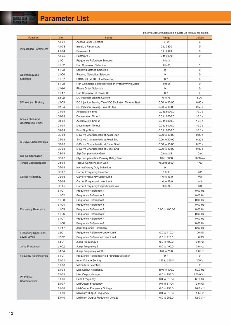
Function No. Name Range Default
Initialization Parameters
A1-01 Access Level Selection 0,2 2
A1-03 Initialize Parameters 0 to 3330 0
A1-04 Password 1 0 to 9999 0
A1-05 Password 2 0 to 9999 0
Operation Mode
Selection
b1-01 Frequency Reference Selection 0 to 3 1
b1-02 Run Command Selection 0 to 2 1
b1-03 Stopping Method Selection 0, 1 0
b1-04 Reverse Operation Selection 0, 1 0
b1-07 LOCAL/REMOTE Run Selection 0, 1 0
b1-08 Run Command Selection while in Programming Mode 0 to 2 0
b1-14 Phase Order Selection 0, 1 0
b1-17 Run Command at Power Up 0, 1 0
DC Injection Braking
b2-02 DC Injection Braking Current 0 to 75 50%
b2-03 DC Injection Braking Time/ DC Excitation Time at Start 0.00 to 10.00 0.00 s
b2-04 DC Injection Braking Time at Stop 0.00 to 10.00 0.50 s
Acceleration and
Deceleration Times
C1-01 Acceleration Time 1 0.0 to 6000.0 10.0 s
C1-02 Deceleration Time 1 0.0 to 6000.0 10.0 s
C1-03 Acceleration Time 2 0.0 to 6000.0 10.0 s
C1-04 Deceleration Time 2 0.0 to 6000.0 10.0 s
C1-09 Fast-Stop Time 0.0 to 6000.0 10.0 s
S-Curve Characteristics
C2-01 S-Curve Characteristic at Accel Start 0.00 to 10.00 0.20 s
C2-02 S-Curve Characteristic at Accel End 0.00 to 10.00 0.20 s
C2-03 S-Curve Characteristic at Decel Start 0.00 to 10.00 0.20 s
C2-04 S-Curve Characteristic at Decel End 0.00 to 10.00 0.00 s
Slip CompensationC3-01 Slip Compensation Gain 0.0 to 2.5 0.0
C3-02 Slip Compensation Primary Delay Time 0 to 10000 2000 ms
Torque Compensation C4-01 Torque Compensation Gain 0.00 to 2.50 1.00
Carrier Frequency
C6-01 Normal/Heavy Duty Selection 0, 1 1
C6-02 Carrier Frequency Selection 1 to F *2
C6-03 Carrier Frequency Upper Limit 1.0 to 15.0 *3
C6-04 Carrier Frequency Lower Limit 1.0 to 15.0 *3
C6-05 Carrier Frequency Proportional Gain 00 to 99 *3
Frequency Reference
d1-01 Frequency Reference 1
0.00 to 400.00
0.00 Hz
d1-02 Frequency Reference 2 0.00 Hz
d1-03 Frequency Reference 3 0.00 Hz
d1-04 Frequency Reference 4 0.00 Hz
d1-05 Frequency Reference 5 0.00 Hz
d1-06 Frequency Reference 6 0.00 Hz
d1-07 Frequency Reference 7 0.00 Hz
d1-08 Frequency Reference 8 0.00 Hz
d1-17 Jog Frequency Reference 6.00 Hz
Frequency Upper and
Lower Limits
d2-01 Frequency Reference Upper Limit 0.0 to 110.0 100.0%
d2-02 Frequency Reference Lower Limit 0.0 to 110.0 0.0%
Jump Frequency
d3-01 Jump Frequency 1 0.0 to 400.0 0.0 Hz
d3-02 Jump Frequency 2 0.0 to 400.0 0.0 Hz
d3-04 Jump Frequency Width 0.0 to 20.0 1.0 Hz
Frequency Reference Hold d4-01 Frequency Reference Hold Function Selection 0, 1 0
V/f Pattern
Characteristics
E1-01 Input Voltage Setting 155 to 255*1 200 V
E1-03 V/f Pattern Selection F F
E1-04 Max Output Frequency 40.0 to 400.0 60.0 Hz
E1-05 Max Output Voltage 0.0 to 255.0 200.0 V*1
E1-06 Base Frequency 0.0 to E1-04 60.0 Hz
E1-07 Mid Output Frequency 0.0 to E1-04 3.0 Hz
E1-08 Mid Output Frequency Voltage 0.0 to 255.0 16.0 V*1
E1-09 Minimum Output Frequency 0.0 to E1-04 1.5 Hz
E1-10 Minimum Output Frequency Voltage 0.0 to 255.0 12.0 V*1
Refer to J1000 Installation & Start-Up Manual for details.
Parameter List
Par
amet
er L
ist
13
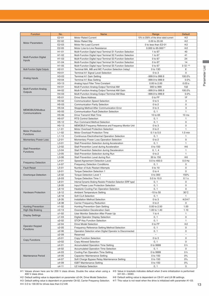
Function No. Name Range Default
Motor Parameters
E2-01 Motor Rated Current 10% to 200% of the drive rated current *2
E2-02 Motor Rated Slip 0.00 to 20.00 *2
E2-03 Motor No-Load Current 0 to less than E2-01 *2
E2-05 Motor Line-to-Line Resistance 0.000 to 65.000*4 *2
Multi-Function Digital Inputs
H1-01 Multi-Function Digital Input Terminal S1 Function Selection 1 to 67 40
H1-02 Multi-Function Digital Input Terminal S2 Function Selection 1 to 67 41
H1-03 Multi-Function Digital Input Terminal S3 Function Selection 0 to 67 24
H1-04 Multi-Function Digital Input Terminal S4 Function Selection 0 to 67 14
H1-05 Multi-Function Digital Input Terminal S5 Function Selection 0 to 67 3(0)*5
Multi-Function Digital Outputs H2-01 Terminal MA, MB and MC Function Selection (relay) 0 to 13D E
Analog Inputs
H3-01 Terminal A1 Signal Level Selection 0 to 3 0
H3-03 Terminal A1 Gain Setting −999.9 to 999.9 100.0%
H3-04 Terminal A1 Bias Setting −999.9 to 999.9 0.0%
H3-13 Analog Input Filter Time Constant 0.00 to 2.00 0.03 s
Multi-Function Analog Outputs
H4-01 Multi-Function Analog Output Terminal AM 000 to 999 102
H4-02 Multi-Function Analog Output Terminal AM Gain −999.9 to 999.9 100.0%
H4-03 Multi-Function Analog Output Terminal AM Bias −999.9 to 999.9 0.0%
MEMOBUS/Modbus Communications
H5-01 Drive Slave Address 0 to FF 1F
H5-02 Communication Speed Selection 0 to 5 3
H5-03 Communication Parity Selection 0 to 2 0
H5-04 Stopping Method After Communication Error 0 to 3 3
H5-05 Communication Fault Detection Selection 0, 1 1
H5-06 Drive Transmit Wait Time 10 to 65 10 ms
H5-07 RTS Control Selection 0, 1 1
H5-12 Run Command Method Selection 0, 1 0
H5-13 MEMOBUS Frequency Reference and Frequency Monitor Unit 0 to 3 0
Motor Protection Functions
L1-01 Motor Overload Protection Selection 0 to 2 1
L1-02 Motor Overload Protection Time 0.1 to 5.0 1.0 min
L1-13 Continuous Electrothermal Operation Selection 0, 1 1
Momentary Power Loss L2-01 Momentary Power Loss Operation Selection 0 to 2 0
Stall Prevention Functions
L3-01 Stall Prevention Selection during Acceleration 0, 1 1
L3-02 Stall Prevention Level during Acceleration 0 to 150 *6
L3-04 Stall Prevention Selection during Deceleration 0, 1, 4 1
L3-05 Stall Prevention Selection during Run 0 to 2 1
L3-06 Stall Prevention Level during Run 30 to 150 *6
Frequency DetectionL4-01 Speed Agreement Detection Level 0.0 to 400.0 0.0 Hz
L4-07 Frequency Detection Conditions 0, 1 0
Fault Reset L5-01 Number of Auto Restart Attempts 0 to 10 0
Overtorque Detection
L6-01 Torque Detection Selection 1 0 to 4 0
L6-02 Torque Detection Level 1 0 to 300 150%
L6-03 Torque Detection Time 1 0.0 to 10.0 0.1 s
Hardware Protection
L8-01 Internal Dynamic Braking Resistor Protection Selection (ERF type) 0, 1 0
L8-05 Input Phase Loss Protection Selection 0, 1 0
L8-10 Heatsink Cooling Fan Operation Selection 0, 1 0
L8-12 Ambient Temperature Setting −10 to 50 30˚C
L8-18 Soft CLA Selection 0, 1 1
L8-35 Installation Method Selection 0 to 3 *2*7
L8-38 Carrier Frequency Reduction 0 to 2 0
Hunting Prevention n1-02 Hunting Prevention Gain Setting 0.00 to 2.50 1.00
High-Slip Braking n3-13 Overexcitation Deceleration Gain 1.00 to 1.40 1.10
Display Settingso1-02 User Monitor Selection After Power Up 1 to 4 1
o1-03 Digital Operator Display Selection 0, 1 0
Operator Keypad Functions
o2-02 STOP Key Function Selection 0, 1 1
o2-04 Drive Model Selection 0 to FF *2
o2-05 Frequency Reference Setting Method Selection 0, 1 0
o2-06 Operation Selection when Digital Operator is Disconnected 0, 1 0
o2-09 Reserved - -
Copy Functionso3-01 Copy Function Selection 0 to 3 0
o3-02 Copy Allowed Selection 0, 1 0
Maintenance Period
o4-01 Accumulated Operation Time Setting 0 to 9999 0 h
o4-02 Accumulated Operation Time Selection 0, 1 0
o4-03 Cooling Fan Operation Time Setting 0 to 9999 0 h
o4-05 Capacitor Maintenance Setting 0 to 150 0%
o4-07 Soft Charge Bypass Relay Maintenance Setting 0 to 150 0%
o4-09 IGBT Maintenance Setting 0 to 150 0%
o4-11 U2 Initialize Selection 0, 1 0
*1: Values shown here are for 200 V class drives. Double the value when using a 400 V class drive.
*2: Default setting value is dependent on parameter o2-04, Drive Model Selection.
*3: Default setting value is dependent on parameter C6-02, Carrier Frequency Selection.
*4: 0.0 to 130.00 for drives less than 0.2 kW.
*5: Value in brackets indicates default when 3-wire initialization is performed (A1-03 = 3330).
*6: Default setting value is dependent on C6-01 and L8-38 settings.
*7: This value is not reset when the drive is initialized with parameter A1-03.
ALM
REV
DRV
FOUT
14
Quick Setup,Easy to Operate
Basic Instructions
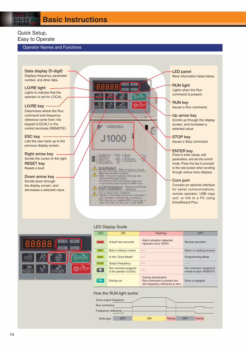
Operator Names and Functions
Data display (5-digit)Displays frequency, parameter number, and other data.
LO/RE lightLights to indicate that the operator is set for LOCAL.
ESC keyLets the user back up to the previous display screen.
Right arrow keyScrolls the cursor to the right.
RUN lightLights when the Run command is present.
RUN keyIssues a Run command.
LED panelMore information listed below.
LO/RE keyDetermines where the Run command and frequency reference come from: the keypad (LOCAL) or the control terminals (REMOTE).
ENTER keyPress to enter values, edit parameters, and set the control mode. Press this key to proceed to the next screen when scrolling through various menu displays.
Com portConnect an optional interface for serial communications, remote operator, USB copy unit, or link to a PC using DriveWizard Plus.
Up arrow keyScrolls up through the display screen, and increases a selected value.
Down arrow keyScrolls down through the display screen, and decreases a selected value.
RESET keyResets a fault.
LED Display Guide
LED ON Flashing OFF
A fault has occurred.・Alarm situation detected.・Operator error (OPE) Normal operation
Motor is rotating in reverse. Motor is rotating forward.
In the "Drive Mode" Programming Mode
Output frequency
Run command assigned to the operator (LOCAL)
Run command assigned to remote location (REMOTE)
During run・During deceleration・Run command is present but
the frequency reference is zero.Drive is stopped.
How the RUN light works:
Drive output frequency
Run command
Frequency reference
RUN light OFF ON Flashing OFF Flashing
STOP keyIssues a Stop command.
1
2
3
4
5
6
7
8
9
10
DRV
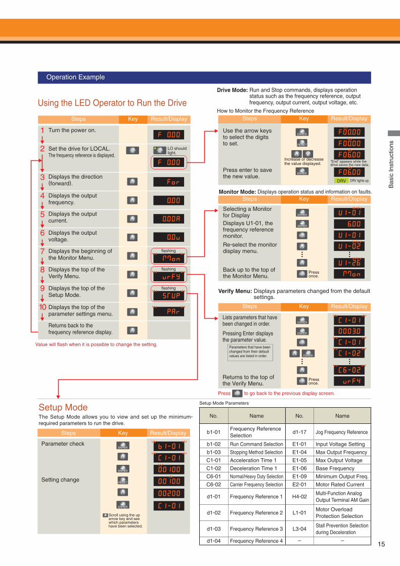
Operation Example
Using the LED Operator to Run the Drive
Steps Key Result/Display
Turn the power on.
Set the drive for LOCAL.The frequency reference is displayed.
Displays the direction (forward).
Displays the output frequency.
Displays the output current.
Displays the output voltage.
Displays the beginning of the Monitor Menu.
Displays the top of the Verify Menu.
Displays the top of the Setup Mode.
Displays the top of the parameter settings menu.
Returns back to the frequency reference display.
Value will fl ash when it is possible to change the setting.
LO should light.
fl ashing
fl ashing
fl ashing
Steps Key Result/Display
Steps Key Result/Display
Steps Key Result/Display
Drive Mode: Run and Stop commands, displays operation status such as the frequency reference, output frequency, output current, output voltage, etc.
How to Monitor the Frequency Reference
Use the arrow keys to select the digits to set.
Press enter to save the new value.
Increase or decrease the value displayed.
“End” appears while the drive saves the new data.
DRV lights up.
Monitor Mode: Displays operation status and information on faults.
Selecting a Monitor for DisplayDisplays U1-01, the frequency reference monitor.
Back up to the top of the Monitor Menu.
Re-select the monitor display menu.
Press once.
Verify Menu: Displays parameters changed from the default settings.
Lists parameters that have been changed in order.
Pressing Enter displays the parameter value.
Returns to the top of the Verify Menu.
Press once.
Parameters that have been changed from their default values are listed in order.
Setup ModeThe Setup Mode allows you to view and set up the minimum-required parameters to run the drive.
Steps Key Result/Display
Parameter check
Setting change
Scroll using the up arrow key and see which parameters have been selected.
Press to go back to the previous display screen.
Setup Mode Parameters
Bas
ic In
stru
ctio
ns
15
No. Name No. Name
b1-01Frequency Reference Selection
d1-17 Jog Frequency Reference
b1-02 Run Command Selection E1-01 Input Voltage Setting
b1-03 Stopping Method Selection E1-04 Max Output Frequency
C1-01 Acceleration Time 1 E1-05 Max Output Voltage
C1-02 Deceleration Time 1 E1-06 Base Frequency
C6-01 Normal/Heavy Duty Selection E1-09 Minimum Output Freq.
C6-02 Carrier Frequency Selection E2-01 Motor Rated Current
d1-01 Frequency Reference 1 H4-02Multi-Function AnalogOutput Terminal AM Gain
d1-02 Frequency Reference 2 L1-01Motor Overload Protection Selection
d1-03 Frequency Reference 3 L3-04Stall Prevention Selectionduring Deceleration
d1-04 Frequency Reference 4 - -
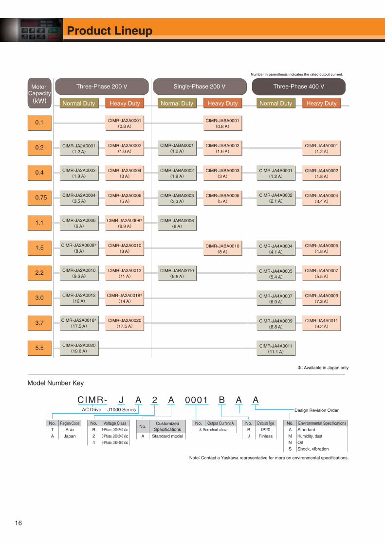
CIMR- J A 2 A 0001 B A A
Heavy DutyNormal Duty Heavy DutyNormal Duty
CIMR-JABA0001(0.8 A)
CIMR-JABA0003(3.3 A)
CIMR-JABA0006(6 A)
CIMR-JA4A0002(1.8 A)
0.2
0.1
0.4
0.75
1.1
1.5
2.2
3.0
3.7
5.5
Motor Capacity
(kW)
Single-Phase 200 V Three-Phase 400 V
CIMR-JABA0002(1.6 A)
CIMR-JABA0001(1.2 A)
CIMR-JA4A0001(1.2 A)
CIMR-JABA0003(3 A)
CIMR-JABA0002(1.9 A)
CIMR-JA4A0004(3.4 A)
CIMR-JA4A0001(1.2 A)
CIMR-JA4A0005(4.8 A)
CIMR-JABA0006(5 A)
CIMR-JABA0010(8 A)
CIMR-JA4A0007(5.5 A)
CIMR-JA4A0009(7.2 A)
CIMR-JA4A0005(5.4 A)
CIMR-JA4A0004(4.1 A)
CIMR-JA4A0007(6.9 A)
CIMR-JA4A0011(11.1 A)
CIMR-JA4A0011(9.2 A)
CIMR-JA4A0009(8.8 A)
CIMR-JABA0010(9.6 A)
Heavy DutyNormal Duty
CIMR-JA2A0001(0.8 A)
Three-Phase 200 V
CIMR-JA2A0002(1.6 A)
CIMR-JA2A0004(3 A)
CIMR-JA2A0008*(6.9 A)
CIMR-JA2A0012(11 A)
CIMR-JA2A0020(17.5 A)
CIMR-JA2A0001(1.2 A)
CIMR-JA2A0002(1.9 A)
CIMR-JA2A0006(6 A)
CIMR-JA2A0010(9.6 A)
CIMR-JA2A0018*(17.5 A)
CIMR-JA2A0006(5 A)
CIMR-JA2A0004(3.5 A)
CIMR-JA2A0010(8 A)
CIMR-JA2A0008*(8 A)
CIMR-JA2A0018*(14 A)
CIMR-JA2A0012(12 A)
CIMR-JA2A0020(19.6 A)
CIMR-JA4A0002(2.1 A)
Number in parenthesis indicates the rated output current.
Model Number Key
AC Drive J1000 Series Design Revision Order
No. Output Current A
* See chart above.
No. Environmental Specifi cations
A Standard
M Humidity, dust
N Oil
S Shock, vibration
No. Region Code
T Asia
A Japan
No. Voltage Class
B 1-Phase, 200-240 Vac
2 3-Phase, 200-240 Vac
4 3-Phase, 380-480 Vac
No.Customized
Specifi cations
A Standard model
No. Enclosure Type
B IP20J Finless
Note: Contact a Yaskawa representative for more on environmental specifi cations.
*: Available in Japan only
16
Product Lineup
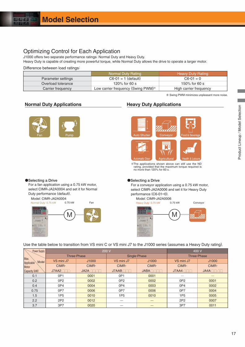
Use the table below to transition from VS mini C or VS mini J7 to the J1000 series (assumes a Heavy Duty rating).
※The applications shown above can still use the ND rating, provided that the maximum torque required is no more than 120% for 60 s.
Food & BeverageFan Auto Shutter ConveyorPump
M M
Normal Duty Applications Heavy Duty Applications
●Selecting a DriveFor a fan application using a 0.75 kW motor,select CIMR-JA2A0004 and set it for NormalDuty performance (default).
●Selecting a DriveFor a conveyor application using a 0.75 kW motor,select CIMR-JA2A0006 and set it for Heavy Dutyperformance (C6-01=0).
Conveyor0.75 kW
Model: CIMR-JA2A0004Fan0.75 kW Heavy Duty: 0.75 kWNormal Duty: 0.75 kW
Model: CIMR-JA2A0006
Automatic Door Agricultural Health & Leisure
Optimizing Control for Each ApplicationJ1000 offers two separate performance ratings: Normal Duty and Heavy Duty. Heavy Duty is capable of creating more powerful torque, while Normal Duty allows the drive to operate a larger motor.
Difference between load ratings:
Normal Duty Rating Heavy Duty RatingParameter settings C6-01 = 1 (default) C6-01 = 0Overload tolerance 120% for 60 s 150% for 60 sCarrier frequency Low carrier frequency (Swing PWM)* High carrier frequency
* Swing PWM minimizes unpleasant more noise.
Pro
duct
Lin
eup
/ Mod
el S
elec
tion
Power Supply 200 V 400 V
Model
Three-Phase Single-Phase Three-Phase
VS mini J7 J1000 VS mini J7 J1000 VS mini J7 J1000
CIMR-
J7AA2
CIMR-
JA2A
CIMR-
J7AAB
CIMR-
JABA
CIMR-
J7AA4
CIMR-
JA4A
0.1 0P1 0001 0P1 0001 0.2 0P2 0002 0P2 0002 0P2 0001
0.4 0P4 0004 0P4 0003 0P4 0002
0.75 0P7 0006 0P7 0006 0P7 0004
1.5 1P5 0010 1P5 0010 1P5 0005
2.2 2P2 0012 2P2 0007
3.7 3P7 0020 3P7 0011
Max. Applicable Motor Capacity (kW)
17
Model Selection
18
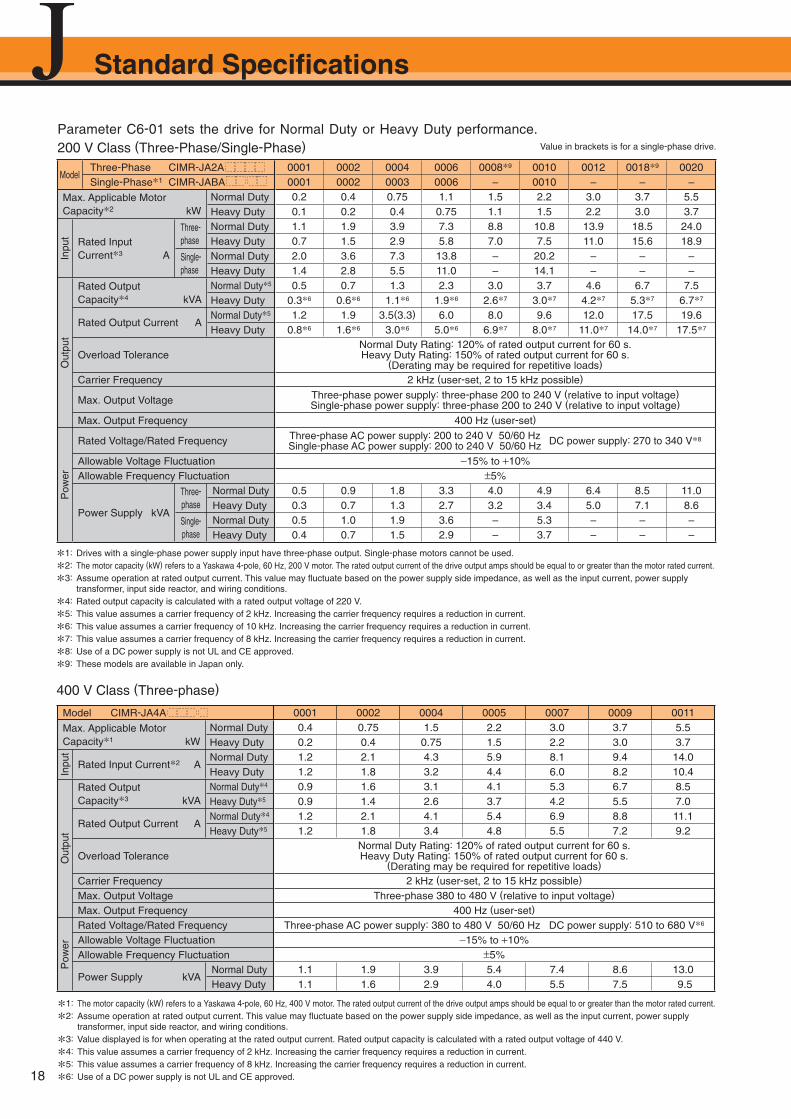
Parameter C6-01 sets the drive for Normal Duty or Heavy Duty performance. 200 V Class (Three-Phase/Single-Phase)
ModelThree-Phase CIMR-JA2A 0001 0002 0004 0006 0008*9 0010 0012 0018*9 0020Single-Phase*1 CIMR-JABA 0001 0002 0003 0006 – 0010 – – –
Max. Applicable Motor Capacity*2 kW
Normal Duty 0.2 0.4 0.75 1.1 1.5 2.2 3.0 3.7 5.5Heavy Duty 0.1 0.2 0.4 0.75 1.1 1.5 2.2 3.0 3.7
Inpu
t Rated Input Current*3 A
Three-phase
Normal Duty 1.1 1.9 3.9 7.3 8.8 10.8 13.9 18.5 24.0Heavy Duty 0.7 1.5 2.9 5.8 7.0 7.5 11.0 15.6 18.9
Single-phase
Normal Duty 2.0 3.6 7.3 13.8 – 20.2 – – –Heavy Duty 1.4 2.8 5.5 11.0 – 14.1 – – –
Out
put
Rated Output Capacity*4 kVA
Normal Duty*5 0.5 0.7 1.3 2.3 3.0 3.7 4.6 6.7 7.5Heavy Duty 0.3*6 0.6*6 1.1*6 1.9*6 2.6*7 3.0*7 4.2*7 5.3*7 6.7*7
Rated Output Current ANormal Duty*5 1.2 1.9 3.5(3.3) 6.0 8.0 9.6 12.0 17.5 19.6Heavy Duty 0.8*6 1.6*6 3.0*6 5.0*6 6.9*7 8.0*7 11.0*7 14.0*7 17.5*7
Overload ToleranceNormal Duty Rating: 120% of rated output current for 60 s.Heavy Duty Rating: 150% of rated output current for 60 s.
(Derating may be required for repetitive loads)
Carrier Frequency 2 kHz (user-set, 2 to 15 kHz possible)
Max. Output Voltage Three-phase power supply: three-phase 200 to 240 V (relative to input voltage)Single-phase power supply: three-phase 200 to 240 V (relative to input voltage)
Max. Output Frequency 400 Hz (user-set)
Pow
er
Rated Voltage/Rated Frequency Three-phase AC power supply: 200 to 240 V 50/60 Hz DC power supply: 270 to 340 V*8Single-phase AC power supply: 200 to 240 V 50/60 Hz
Allowable Voltage Fluctuation −15% to +10%Allowable Frequency Fluctuation ±5%
Power Supply kVA
Three-phase
Normal Duty 0.5 0.9 1.8 3.3 4.0 4.9 6.4 8.5 11.0Heavy Duty 0.3 0.7 1.3 2.7 3.2 3.4 5.0 7.1 8.6
Single-phase
Normal Duty 0.5 1.0 1.9 3.6 – 5.3 – – –Heavy Duty 0.4 0.7 1.5 2.9 – 3.7 – – –
*1: Drives with a single-phase power supply input have three-phase output. Single-phase motors cannot be used.
*2: The motor capacity (kW) refers to a Yaskawa 4-pole, 60 Hz, 200 V motor. The rated output current of the drive output amps should be equal to or greater than the motor rated current.
*3: Assume operation at rated output current. This value may fl uctuate based on the power supply side impedance, as well as the input current, power supply transformer, input side reactor, and wiring conditions.
*4: Rated output capacity is calculated with a rated output voltage of 220 V.
*5: This value assumes a carrier frequency of 2 kHz. Increasing the carrier frequency requires a reduction in current.
*6: This value assumes a carrier frequency of 10 kHz. Increasing the carrier frequency requires a reduction in current.
*7: This value assumes a carrier frequency of 8 kHz. Increasing the carrier frequency requires a reduction in current.
*8: Use of a DC power supply is not UL and CE approved.
*9: These models are available in Japan only.
Value in brackets is for a single-phase drive.
Model CIMR-JA4A 0001 0002 0004 0005 0007 0009 0011
Max. Applicable Motor Capacity*1 kW
Normal Duty 0.4 0.75 1.5 2.2 3.0 3.7 5.5Heavy Duty 0.2 0.4 0.75 1.5 2.2 3.0 3.7
Inpu
t
Rated Input Current*2 ANormal Duty 1.2 2.1 4.3 5.9 8.1 9.4 14.0Heavy Duty 1.2 1.8 3.2 4.4 6.0 8.2 10.4
Out
put
Rated Output Capacity*3 kVA
Normal Duty*4 0.9 1.6 3.1 4.1 5.3 6.7 8.5Heavy Duty*5 0.9 1.4 2.6 3.7 4.2 5.5 7.0
Rated Output Current ANormal Duty*4 1.2 2.1 4.1 5.4 6.9 8.8 11.1Heavy Duty*5 1.2 1.8 3.4 4.8 5.5 7.2 9.2
Overload ToleranceNormal Duty Rating: 120% of rated output current for 60 s. Heavy Duty Rating: 150% of rated output current for 60 s.
(Derating may be required for repetitive loads)
Carrier Frequency 2 kHz (user-set, 2 to 15 kHz possible)
Max. Output Voltage Three-phase 380 to 480 V (relative to input voltage)
Max. Output Frequency 400 Hz (user-set)
Pow
er
Rated Voltage/Rated Frequency Three-phase AC power supply: 380 to 480 V 50/60 Hz DC power supply: 510 to 680 V*6
Allowable Voltage Fluctuation −15% to +10%Allowable Frequency Fluctuation ±5%
Power Supply kVANormal Duty 1.1 1.9 3.9 5.4 7.4 8.6 13.0Heavy Duty 1.1 1.6 2.9 4.0 5.5 7.5 9.5
400 V Class (Three-phase)
*1: The motor capacity (kW) refers to a Yaskawa 4-pole, 60 Hz, 400 V motor. The rated output current of the drive output amps should be equal to or greater than the motor rated current.
*2: Assume operation at rated output current. This value may fl uctuate based on the power supply side impedance, as well as the input current, power supply transformer, input side reactor, and wiring conditions.
*3: Value displayed is for when operating at the rated output current. Rated output capacity is calculated with a rated output voltage of 440 V.
*4: This value assumes a carrier frequency of 2 kHz. Increasing the carrier frequency requires a reduction in current.
*5: This value assumes a carrier frequency of 8 kHz. Increasing the carrier frequency requires a reduction in current.
*6: Use of a DC power supply is not UL and CE approved.
Standard Specifi cations
19
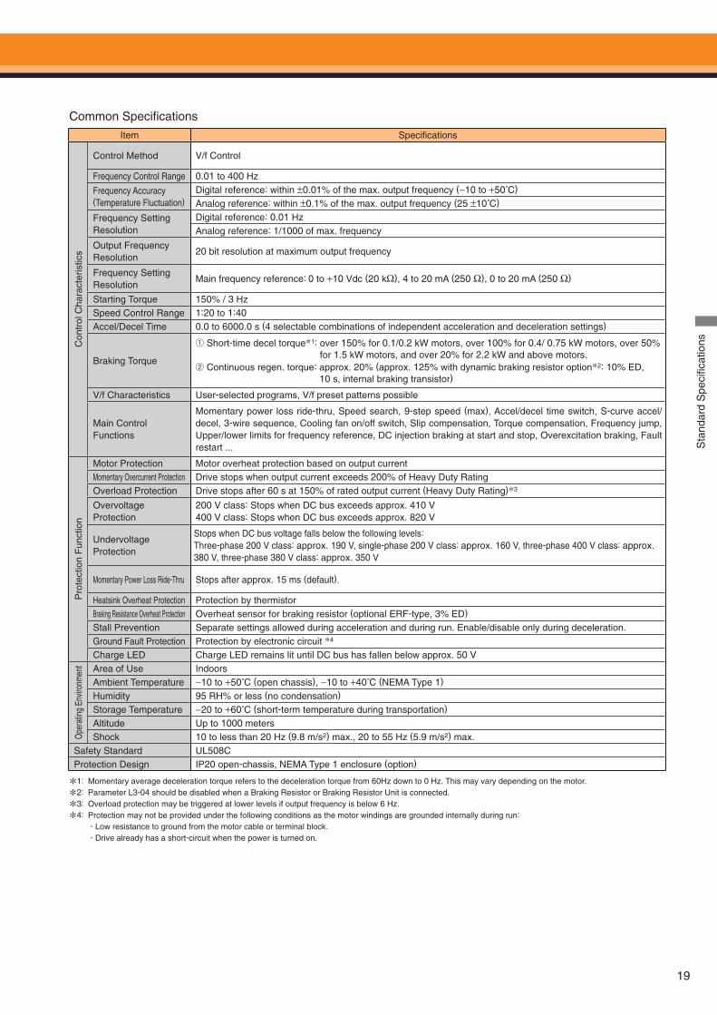
Item Specifi cations
Con
trol
Cha
ract
eris
tics
Control Method V/f Control
Frequency Control Range 0.01 to 400 Hz
Frequency Accuracy (Temperature Fluctuation)
Digital reference: within ±0.01% of the max. output frequency (−10 to +50˚C)
Analog reference: within ±0.1% of the max. output frequency (25 ±10˚C)
Frequency Setting Resolution
Digital reference: 0.01 HzAnalog reference: 1/1000 of max. frequency
Output Frequency Resolution
20 bit resolution at maximum output frequency
Frequency Setting Resolution
Main frequency reference: 0 to +10 Vdc (20 kΩ), 4 to 20 mA (250 Ω), 0 to 20 mA (250 Ω)
Starting Torque 150% / 3 HzSpeed Control Range 1:20 to 1:40Accel/Decel Time 0.0 to 6000.0 s (4 selectable combinations of independent acceleration and deceleration settings)
Braking Torque
① Short-time decel torque*1: over 150% for 0.1/0.2 kW motors, over 100% for 0.4/ 0.75 kW motors, over 50% for 1.5 kW motors, and over 20% for 2.2 kW and above motors.
② Continuous regen. torque: approx. 20% (approx. 125% with dynamic braking resistor option*2: 10% ED, 10 s, internal braking transistor)
V/f Characteristics User-selected programs, V/f preset patterns possible
Main Control Functions
Momentary power loss ride-thru, Speed search, 9-step speed (max), Accel/decel time switch, S-curve accel/decel, 3-wire sequence, Cooling fan on/off switch, Slip compensation, Torque compensation, Frequency jump, Upper/lower limits for frequency reference, DC injection braking at start and stop, Overexcitation braking, Fault restart ...
Pro
tect
ion
Fun
ctio
n
Motor Protection Motor overheat protection based on output currentMomentary Overcurrent Protection Drive stops when output current exceeds 200% of Heavy Duty RatingOverload Protection Drive stops after 60 s at 150% of rated output current (Heavy Duty Rating)*3
Overvoltage Protection
200 V class: Stops when DC bus exceeds approx. 410 V400 V class: Stops when DC bus exceeds approx. 820 V
Undervoltage Protection
Stops when DC bus voltage falls below the following levels:Three-phase 200 V class: approx. 190 V, single-phase 200 V class: approx. 160 V, three-phase 400 V class: approx. 380 V, three-phase 380 V class: approx. 350 V
Momentary Power Loss Ride-Thru Stops after approx. 15 ms (default).
Heatsink Overheat Protection Protection by thermistorBraking Resistance Overheat Protection Overheat sensor for braking resistor (optional ERF-type, 3% ED)
Stall Prevention Separate settings allowed during acceleration and during run. Enable/disable only during deceleration.Ground Fault Protection Protection by electronic circuit *4
Charge LED Charge LED remains lit until DC bus has fallen below approx. 50 V
Ope
ratin
g En
viron
men
t Area of Use IndoorsAmbient Temperature −10 to +50˚C (open chassis), −10 to +40˚C (NEMA Type 1)
Humidity 95 RH% or less (no condensation)
Storage Temperature −20 to +60˚C (short-term temperature during transportation)
Altitude Up to 1000 metersShock 10 to less than 20 Hz (9.8 m/s2) max., 20 to 55 Hz (5.9 m/s2) max.
Safety Standard UL508CProtection Design IP20 open-chassis, NEMA Type 1 enclosure (option)
*1: Momentary average deceleration torque refers to the deceleration torque from 60Hz down to 0 Hz. This may vary depending on the motor.
*2: Parameter L3-04 should be disabled when a Braking Resistor or Braking Resistor Unit is connected.
*3: Overload protection may be triggered at lower levels if output frequency is below 6 Hz.
*4: Protection may not be provided under the following conditions as the motor windings are grounded internally during run:
û Low resistance to ground from the motor cable or terminal block. û Drive already has a short-circuit when the power is turned on.
Common Specifi cations
Sta
ndar
d S
peci
ficat
ions
20
shielded line, twisted-pair shielded line main circuit terminal control terminal.
M
M
ELCB or MCCB MC Fuse
2MCCBr1
U X
s1t1
R/L1
S/L2
T/L3
U/T1
V/T2
W/T3
r1s1t1
S1
S2
S3
S4
S5
+24 V
DIP switchS3
SINK
SOURCESC
Shield groundterminal
MA
MB
MC
AM
AC
Motor
Cooling fan
GroundOption unitconnector
DIP switch S1VI
FUFVFW
U
V
W
Main frequencyreference
Setting power supply +10.5 V max. 20 mAMain frequency reference0 to +10 V (20 kΩ) or4 to 20 mA (250 Ω) /0 to 20 mA (250 Ω)
Frequency Setting Potentiometer
R
S
T
+V
A1
AC
Three-phasepower supply200 to 240 V50/60 Hz
For single-phase 200 V power supply, use R/L1 and S/L2.
Wiring sequence should shut off power to the drive when a fault output is triggered.
Terminals +1, +2, − , B1, and B2 are for connecting options. Never connect power supply lines to these terminals.
Main circuit
Control circuit
J1000
DC reactor (option)
Jumper
Thermal relay (option) Braking resistor
(option)
− B1+1+2 B2
Multi-function digital output(default)250 Vac, 10 mA to 1 A30 Vdc, 10 mA to 1 A
Fault
Fault
Monitor output
Forward run/stop
Reverse run/stop
External fault
Fault reset
Multi-Step speed 1
Multi-function digital input(default)
2 kΩ
2
3
1
+24 V 8 mA
Analog monitor output0 to +10 Vdc (2 mA)Output frequency(default)
+
−
*4
*3
*1*2
*7
*6
*5
AM
Frequency potentiometer20 kΩ
A separate transformer is required when running from a 400 V power supply to step the voltage down to 200 V.
ONOFFTHRX
SA
1 2
TRX
MC MA
MC
TRX
Fault relay contact
Braking resistor unitThermal relay trip contact
MC
SA
SA
THRX
2MCCBMC MB
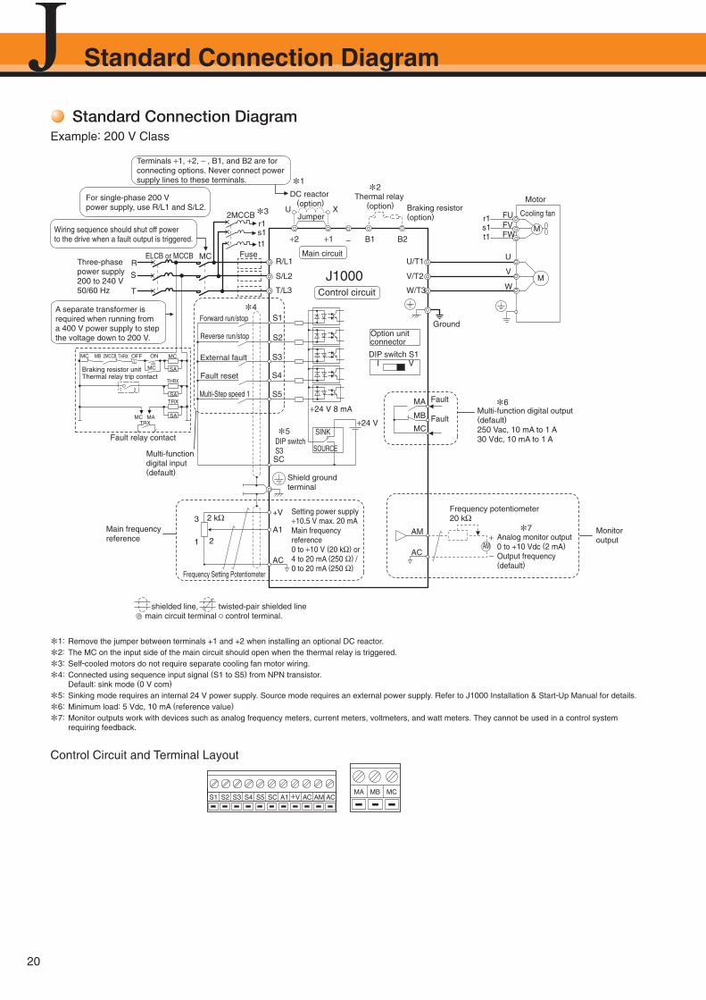
Standard Connection DiagramExample: 200 V Class
*1: Remove the jumper between terminals +1 and +2 when installing an optional DC reactor.
*2: The MC on the input side of the main circuit should open when the thermal relay is triggered.
*3: Self-cooled motors do not require separate cooling fan motor wiring.
*4: Connected using sequence input signal (S1 to S5) from NPN transistor. Default: sink mode (0 V com)
*5: Sinking mode requires an internal 24 V power supply. Source mode requires an external power supply. Refer to J1000 Installation & Start-Up Manual for details.
*6: Minimum load: 5 Vdc, 10 mA (reference value)
*7: Monitor outputs work with devices such as analog frequency meters, current meters, voltmeters, and watt meters. They cannot be used in a control system requiring feedback.
Control Circuit and Terminal Layout
S1 S2 S3 S4 S5 SC A1 +V AC AM ACMCMBMA
Standard Connection Diagram
21
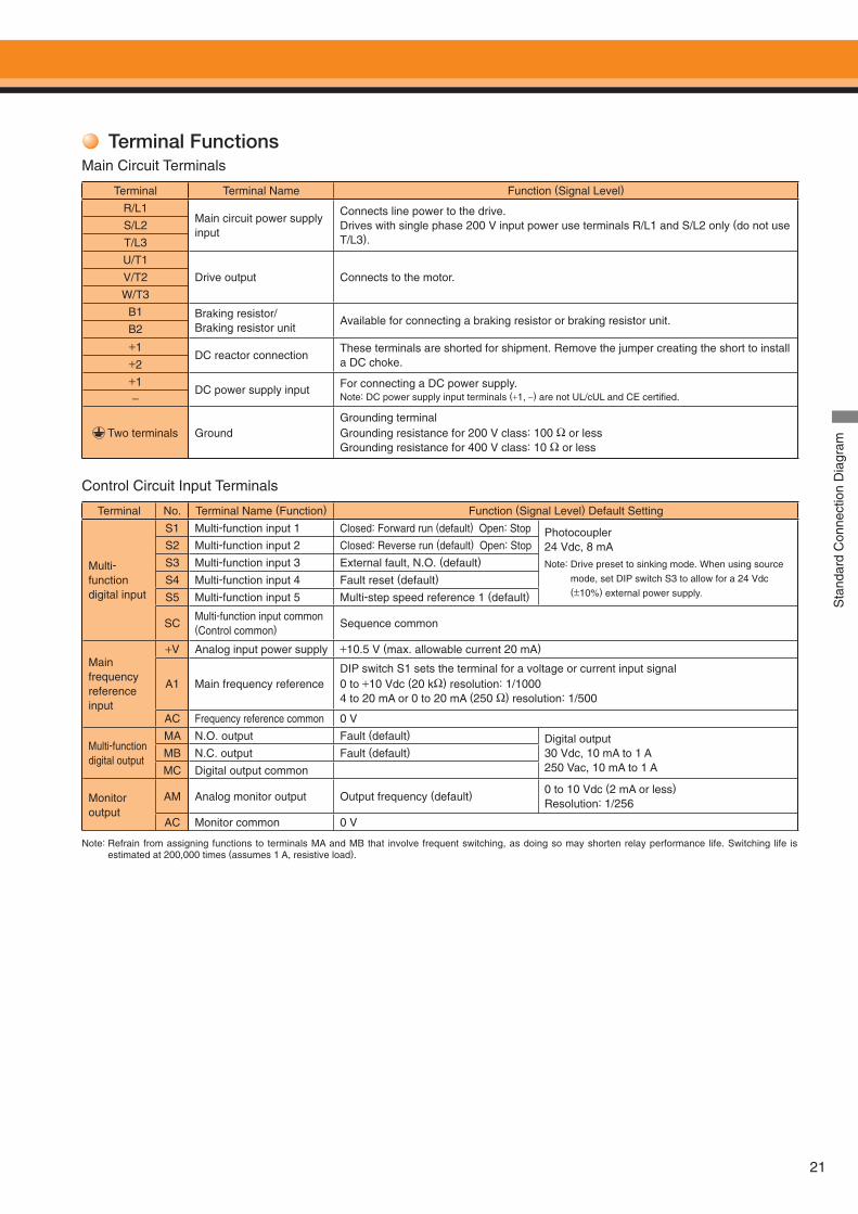
Terminal FunctionsMain Circuit Terminals
Control Circuit Input Terminals
Terminal Terminal Name Function (Signal Level)
R/L1Main circuit power supply input
Connects line power to the drive.Drives with single phase 200 V input power use terminals R/L1 and S/L2 only (do not use T/L3).
S/L2
T/L3
U/T1
Drive output Connects to the motor.V/T2
W/T3
B1 Braking resistor/Braking resistor unit
Available for connecting a braking resistor or braking resistor unit.B2
+1DC reactor connection
These terminals are shorted for shipment. Remove the jumper creating the short to install a DC choke.+2
+1DC power supply input For connecting a DC power supply.
Note: DC power supply input terminals (+1, −) are not UL/cUL and CE certifi ed.−
Two terminals GroundGrounding terminalGrounding resistance for 200 V class: 100 Ω or lessGrounding resistance for 400 V class: 10 Ω or less
Terminal No. Terminal Name (Function) Function (Signal Level) Default Setting
Multi-function digital input
S1 Multi-function input 1 Closed: Forward run (default) Open: Stop Photocoupler24 Vdc, 8 mA
Note: Drive preset to sinking mode. When using source
mode, set DIP switch S3 to allow for a 24 Vdc (±10%) external power supply.
S2 Multi-function input 2 Closed: Reverse run (default) Open: Stop
S3 Multi-function input 3 External fault, N.O. (default)
S4 Multi-function input 4 Fault reset (default)
S5 Multi-function input 5 Multi-step speed reference 1 (default)
SCMulti-function input common (Control common) Sequence common
Main frequency reference input
+V Analog input power supply +10.5 V (max. allowable current 20 mA)
A1 Main frequency referenceDIP switch S1 sets the terminal for a voltage or current input signal0 to +10 Vdc (20 kΩ) resolution: 1/10004 to 20 mA or 0 to 20 mA (250 Ω) resolution: 1/500
AC Frequency reference common 0 V
Multi-function digital output
MA N.O. output Fault (default) Digital output30 Vdc, 10 mA to 1 A250 Vac, 10 mA to 1 A
MB N.C. output Fault (default)
MC Digital output common
Monitor output
AM Analog monitor output Output frequency (default)0 to 10 Vdc (2 mA or less)Resolution: 1/256
AC Monitor common 0 VS
tand
ard
Con
nect
ion
Dia
gram
Note: Refrain from assigning functions to terminals MA and MB that involve frequent switching, as doing so may shorten relay performance life. Switching life is estimated at 200,000 times (assumes 1 A, resistive load).
22
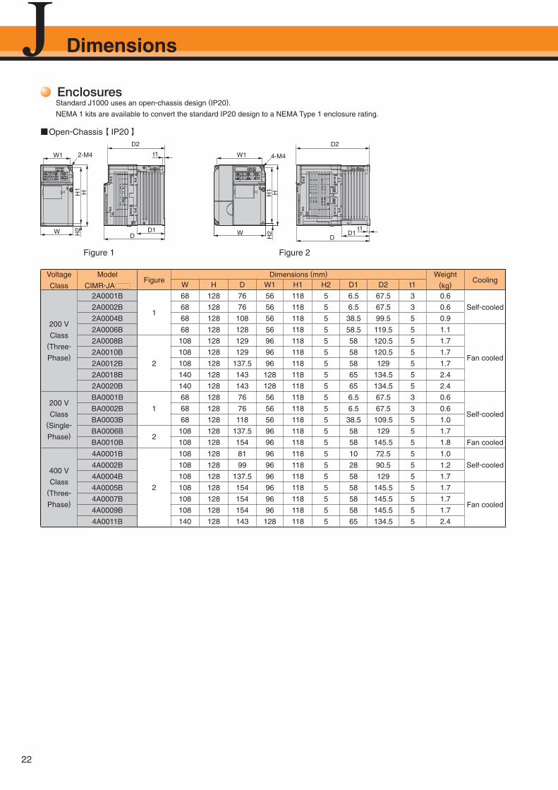
Enclosures Standard J1000 uses an open-chassis design (IP20).
NEMA 1 kits are available to convert the standard IP20 design to a NEMA Type 1 enclosure rating.
Figure 1 Figure 2
■Open-Chassis 【 IP20 】
Voltage
Class
Model
CIMR-JAFigure
Dimensions (mm) Weight(kg)
CoolingW H D W1 H1 H2 D1 D2 t1
200 V
Class (Three-
Phase)
2A0001B
1
68 128 76 56 118 5 6.5 67.5 3 0.6
Self-cooled2A0002B 68 128 76 56 118 5 6.5 67.5 3 0.6
2A0004B 68 128 108 56 118 5 38.5 99.5 5 0.9
2A0006B 68 128 128 56 118 5 58.5 119.5 5 1.1
Fan cooled
2A0008B
2
108 128 129 96 118 5 58 120.5 5 1.7
2A0010B 108 128 129 96 118 5 58 120.5 5 1.7
2A0012B 108 128 137.5 96 118 5 58 129 5 1.7
2A0018B 140 128 143 128 118 5 65 134.5 5 2.4
2A0020B 140 128 143 128 118 5 65 134.5 5 2.4
200 V
Class (Single-
Phase)
BA0001B
1
68 128 76 56 118 5 6.5 67.5 3 0.6
Self-cooledBA0002B 68 128 76 56 118 5 6.5 67.5 3 0.6
BA0003B 68 128 118 56 118 5 38.5 109.5 5 1.0
BA0006B2
108 128 137.5 96 118 5 58 129 5 1.7
BA0010B 108 128 154 96 118 5 58 145.5 5 1.8 Fan cooled
400 V
Class (Three-
Phase)
4A0001B
2
108 128 81 96 118 5 10 72.5 5 1.0
Self-cooled4A0002B 108 128 99 96 118 5 28 90.5 5 1.2
4A0004B 108 128 137.5 96 118 5 58 129 5 1.7
4A0005B 108 128 154 96 118 5 58 145.5 5 1.7
Fan cooled4A0007B 108 128 154 96 118 5 58 145.5 5 1.7
4A0009B 108 128 154 96 118 5 58 145.5 5 1.7
4A0011B 140 128 143 128 118 5 65 134.5 5 2.4
t1
D1
D2
DW
H1
H2
H
2-M4W1
t1D
D1
4-M4
H
W1
W
H2
H1
D2
Dimensions
23
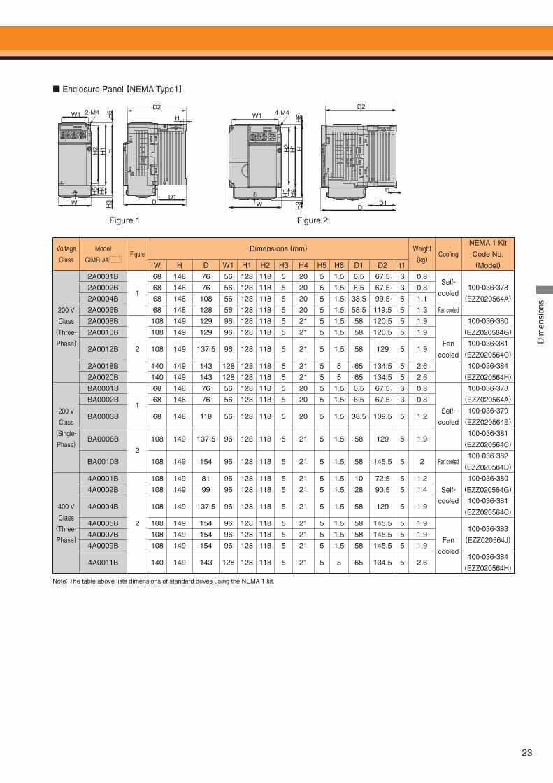
■ Enclosure Panel 【NEMA Type1】
Figure 1 Figure 2
Voltage
Class
Model
CIMR-JAFigure
Dimensions (mm) Weight(kg)
Cooling
NEMA 1 Kit
Code No.(Model)W H D W1 H1 H2 H3 H4 H5 H6 D1 D2 t1
200 V
Class (Three-
Phase)
2A0001B
1
68 148 76 56 128 118 5 20 5 1.5 6.5 67.5 3 0.8Self-
cooled100-036-378
(EZZ020564A)2A0002B 68 148 76 56 128 118 5 20 5 1.5 6.5 67.5 3 0.8
2A0004B 68 148 108 56 128 118 5 20 5 1.5 38.5 99.5 5 1.1
2A0006B 68 148 128 56 128 118 5 20 5 1.5 58.5 119.5 5 1.3 Fan cooled
2A0008B
2
108 149 129 96 128 118 5 21 5 1.5 58 120.5 5 1.9
Fan
cooled
100-036-380(EZZ020564G)2A0010B 108 149 129 96 128 118 5 21 5 1.5 58 120.5 5 1.9
2A0012B 108 149 137.5 96 128 118 5 21 5 1.5 58 129 5 1.9100-036-381
(EZZ020564C)
2A0018B 140 149 143 128 128 118 5 21 5 5 65 134.5 5 2.6 100-036-384(EZZ020564H)2A0020B 140 149 143 128 128 118 5 21 5 5 65 134.5 5 2.6
200 V
Class (Single-
Phase)
BA0001B
1
68 148 76 56 128 118 5 20 5 1.5 6.5 67.5 3 0.8
Self-
cooled
100-036-378(EZZ020564A)BA0002B 68 148 76 56 128 118 5 20 5 1.5 6.5 67.5 3 0.8
BA0003B 68 148 118 56 128 118 5 20 5 1.5 38.5 109.5 5 1.2100-036-379
(EZZ020564B)
BA0006B
2
108 149 137.5 96 128 118 5 21 5 1.5 58 129 5 1.9100-036-381
(EZZ020564C)
BA0010B 108 149 154 96 128 118 5 21 5 1.5 58 145.5 5 2 Fan cooled100-036-382
(EZZ020564D)
400 V
Class (Three-
Phase)
4A0001B
2
108 149 81 96 128 118 5 21 5 1.5 10 72.5 5 1.2
Self-
cooled
100-036-380(EZZ020564G)4A0002B 108 149 99 96 128 118 5 21 5 1.5 28 90.5 5 1.4
4A0004B 108 149 137.5 96 128 118 5 21 5 1.5 58 129 5 1.9100-036-381
(EZZ020564C)
4A0005B 108 149 154 96 128 118 5 21 5 1.5 58 145.5 5 1.9
Fan
cooled
100-036-383(EZZ020564J)
4A0007B 108 149 154 96 128 118 5 21 5 1.5 58 145.5 5 1.9
4A0009B 108 149 154 96 128 118 5 21 5 1.5 58 145.5 5 1.9
4A0011B 140 149 143 128 128 118 5 21 5 5 65 134.5 5 2.6100-036-384
(EZZ020564H)
Note: The table above lists dimensions of standard drives using the NEMA 1 kit.
WD1
D2
D
W1 2-M4t1
H1
H4
H5
H2 H
H3
H6 4-M4W1
W
H5
H2
H4
HH
3H
1H
6
D1
D2
D
t1
Dim
ensi
ons
24
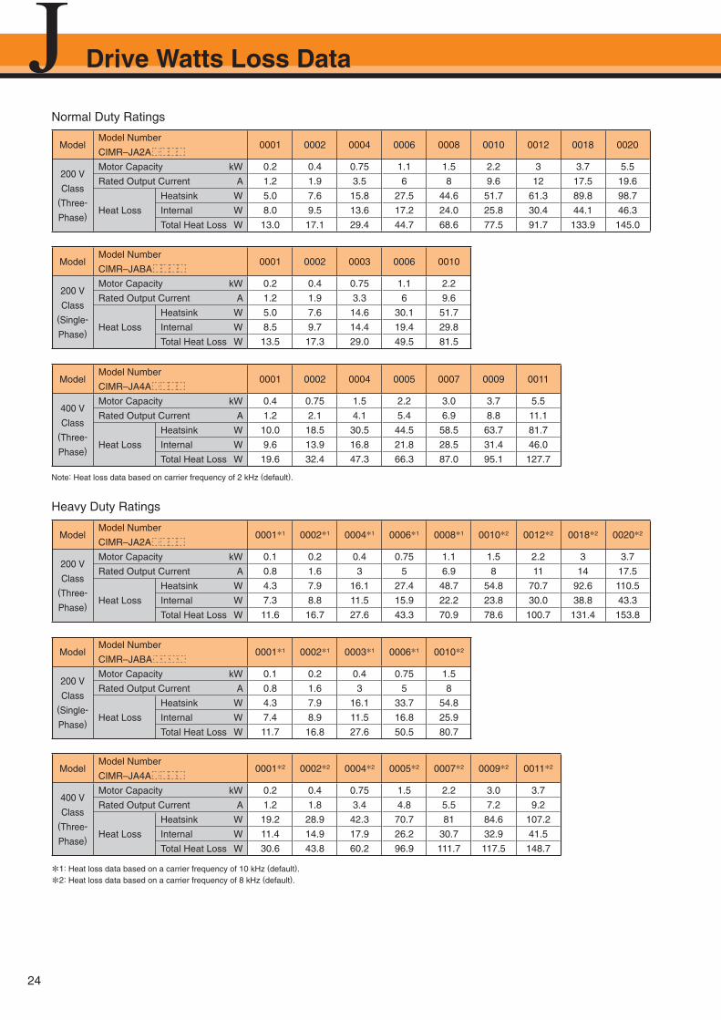
ModelModel Number
CIMR–JA2A0001 0002 0004 0006 0008 0010 0012 0018 0020
200 V
Class(Three-
Phase)
Motor Capacity kW 0.2 0.4 0.75 1.1 1.5 2.2 3 3.7 5.5
Rated Output Current A 1.2 1.9 3.5 6 8 9.6 12 17.5 19.6
Heat Loss
Heatsink W 5.0 7.6 15.8 27.5 44.6 51.7 61.3 89.8 98.7
Internal W 8.0 9.5 13.6 17.2 24.0 25.8 30.4 44.1 46.3
Total Heat Loss W 13.0 17.1 29.4 44.7 68.6 77.5 91.7 133.9 145.0
Normal Duty Ratings
Heavy Duty Ratings
Note: Heat loss data based on carrier frequency of 2 kHz (default).
*1: Heat loss data based on a carrier frequency of 10 kHz (default).
*2: Heat loss data based on a carrier frequency of 8 kHz (default).
ModelModel Number
CIMR–JA2A0001*1 0002*1 0004*1 0006*1 0008*1 0010*2 0012*2 0018*2 0020*2
200 V
Class(Three-
Phase)
Motor Capacity kW 0.1 0.2 0.4 0.75 1.1 1.5 2.2 3 3.7
Rated Output Current A 0.8 1.6 3 5 6.9 8 11 14 17.5
Heat Loss
Heatsink W 4.3 7.9 16.1 27.4 48.7 54.8 70.7 92.6 110.5
Internal W 7.3 8.8 11.5 15.9 22.2 23.8 30.0 38.8 43.3
Total Heat Loss W 11.6 16.7 27.6 43.3 70.9 78.6 100.7 131.4 153.8
ModelModel Number
CIMR–JABA0001 0002 0003 0006 0010
200 V
Class(Single-
Phase)
Motor Capacity kW 0.2 0.4 0.75 1.1 2.2
Rated Output Current A 1.2 1.9 3.3 6 9.6
Heat Loss
Heatsink W 5.0 7.6 14.6 30.1 51.7
Internal W 8.5 9.7 14.4 19.4 29.8
Total Heat Loss W 13.5 17.3 29.0 49.5 81.5
ModelModel Number
CIMR–JA4A0001 0002 0004 0005 0007 0009 0011
400 V
Class(Three-
Phase)
Motor Capacity kW 0.4 0.75 1.5 2.2 3.0 3.7 5.5
Rated Output Current A 1.2 2.1 4.1 5.4 6.9 8.8 11.1
Heat Loss
Heatsink W 10.0 18.5 30.5 44.5 58.5 63.7 81.7
Internal W 9.6 13.9 16.8 21.8 28.5 31.4 46.0
Total Heat Loss W 19.6 32.4 47.3 66.3 87.0 95.1 127.7
ModelModel Number
CIMR–JABA0001*1 0002*1 0003*1 0006*1 0010*2
200 V
Class(Single-
Phase)
Motor Capacity kW 0.1 0.2 0.4 0.75 1.5
Rated Output Current A 0.8 1.6 3 5 8
Heat Loss
Heatsink W 4.3 7.9 16.1 33.7 54.8
Internal W 7.4 8.9 11.5 16.8 25.9
Total Heat Loss W 11.7 16.8 27.6 50.5 80.7
ModelModel Number
CIMR–JA4A0001*2 0002*2 0004*2 0005*2 0007*2 0009*2 0011*2
400 V
Class(Three-
Phase)
Motor Capacity kW 0.2 0.4 0.75 1.5 2.2 3.0 3.7
Rated Output Current A 1.2 1.8 3.4 4.8 5.5 7.2 9.2
Heat Loss
Heatsink W 19.2 28.9 42.3 70.7 81 84.6 107.2
Internal W 11.4 14.9 17.9 26.2 30.7 32.9 41.5
Total Heat Loss W 30.6 43.8 60.2 96.9 111.7 117.5 148.7
Drive Watts Loss Data
25
Cooled air
Cooled air
Mounting surface
Wal
l10
0 m
m m
in.
100
mm
min
.
D3 min.D1 D2
ALM
ESC
RESET ENTERSTOP
RUNLORE
DRV FOUT
REV
W
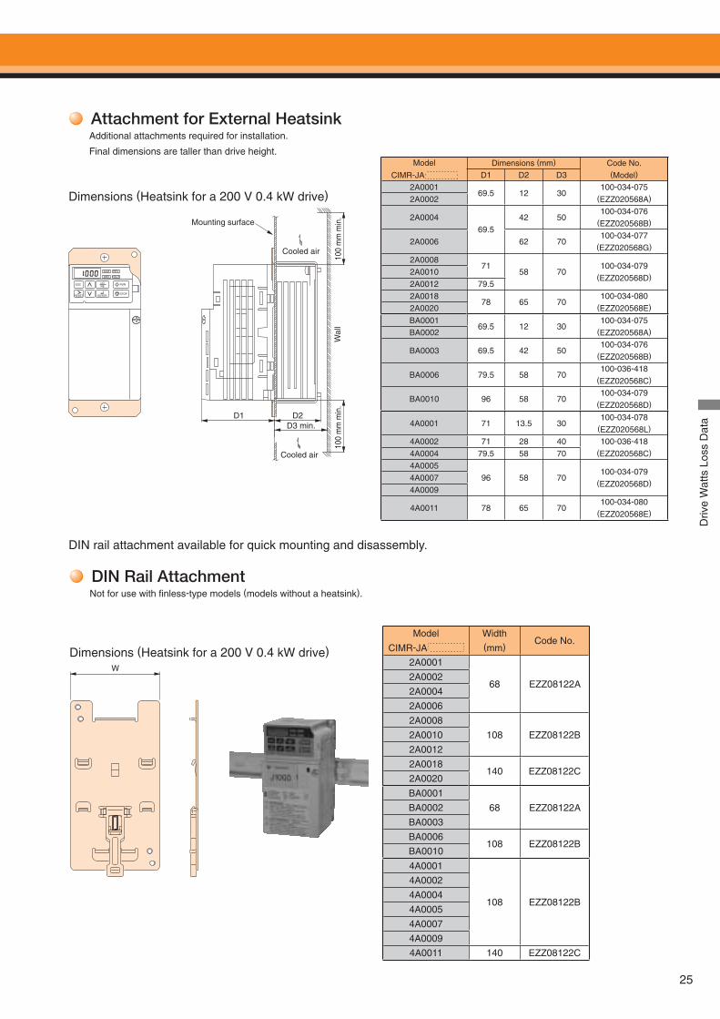
Attachment for External HeatsinkAdditional attachments required for installation.
Final dimensions are taller than drive height.
DIN Rail AttachmentNot for use with fi nless-type models (models without a heatsink).
Model
CIMR-JA
Width (mm)
Code No.
2A0001
68 EZZ08122A2A0002
2A0004
2A0006
2A0008
108 EZZ08122B2A0010
2A0012
2A0018140 EZZ08122C
2A0020
BA0001
68 EZZ08122ABA0002
BA0003
BA0006108 EZZ08122B
BA0010
4A0001
108 EZZ08122B
4A0002
4A0004
4A0005
4A0007
4A0009
4A0011 140 EZZ08122C
Model
CIMR-JA
Dimensions (mm) Code No.(Model)D1 D2 D3
2A000169.5 12 30
100-034-075(EZZ020568A)2A0002
2A000469.5
42 50100-034-076
(EZZ020568B)
2A0006 62 70100-034-077
(EZZ020568G)
2A000871
58 70100-034-079
(EZZ020568D)2A00102A0012 79.52A0018
78 65 70100-034-080
(EZZ020568E)2A0020
BA000169.5 12 30
100-034-075(EZZ020568A)BA0002
BA0003 69.5 42 50100-034-076
(EZZ020568B)
BA0006 79.5 58 70100-036-418
(EZZ020568C)
BA0010 96 58 70100-034-079
(EZZ020568D)
4A0001 71 13.5 30100-034-078
(EZZ020568L)
4A0002 71 28 40 100-036-418(EZZ020568C)4A0004 79.5 58 70
4A000596 58 70
100-034-079(EZZ020568D)
4A00074A0009
4A0011 78 65 70100-034-080
(EZZ020568E)
DIN rail attachment available for quick mounting and disassembly.
Dimensions (Heatsink for a 200 V 0.4 kW drive)
Dimensions (Heatsink for a 200 V 0.4 kW drive)
Driv
e W
atts
Los
s D
ata
26
B1
B2
+2
+1
Fuse
Fusible disconnect Ground FaultInterrupter,Circuit Breaker (MCCB)
Power Supply
Magnetic Contactor
Surge Protector
AC Reactor
Input Noise Filter
Zero Phase Reactor
DC Reactor
Braking Resistor or Braking Resistor Unit
Noise Filter (Output side)
Isolator
Zero Phase Reactor
Motor
Ground
PC
Interface Option
DriveWizardPlus
Serial Comm Port
USB Copy Unit(RJ-45/USB adopter)
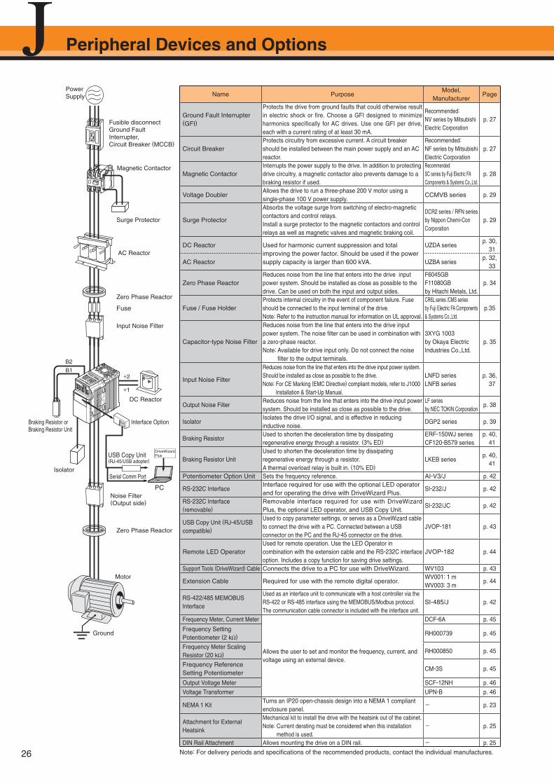
Name PurposeModel,
ManufacturerPage
Ground Fault Interrupter (GFI)
Protects the drive from ground faults that could otherwise result in electric shock or fire. Choose a GFI designed to minimize harmonics specifically for AC drives. Use one GFI per drive, each with a current rating of at least 30 mA.
Recommended:NV series by Mitsubishi Electric Corporation
p. 27
Circuit BreakerProtects circuitry from excessive current. A circuit breaker should be installed between the main power supply and an AC reactor.
Recommended:NF series by Mitsubishi Electric Corporation
p. 27
Magnetic ContactorInterrupts the power supply to the drive. In addition to protecting drive circuitry, a magnetic contactor also prevents damage to a braking resistor if used.
Recommended:SC series by Fuji Electric FA Components & Systems Co.,Ltd.
p. 28
Voltage DoublerAllows the drive to run a three-phase 200 V motor using a single-phase 100 V power supply.
CCMVB series p. 29
Surge Protector
Absorbs the voltage surge from switching of electro-magnetic contactors and control relays.Install a surge protector to the magnetic contactors and control relays as well as magnetic valves and magnetic braking coil.
DCR2 series / RFN seriesby Nippon Chemi-Con Corporation
p. 29
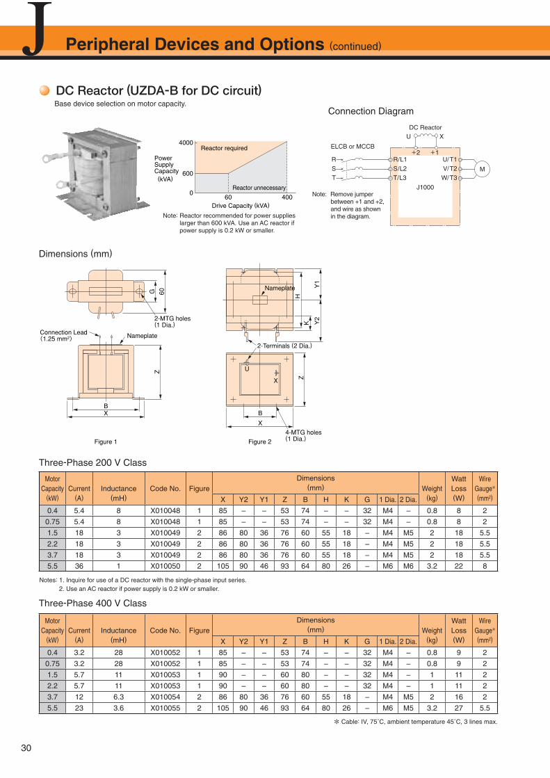
DC Reactor Used for harmonic current suppression and total improving the power factor. Should be used if the power supply capacity is larger than 600 kVA.
UZDA seriesp. 30, 31
AC Reactor UZBA seriesp. 32, 33
Zero Phase ReactorReduces noise from the line that enters into the drive input power system. Should be installed as close as possible to the drive. Can be used on both the input and output sides.
F6045GBF11080GB by Hitachi Metals, Ltd.
p. 34
Fuse / Fuse HolderProtects internal circuitry in the event of component failure. Fuse should be connected to the input terminal of the drive.Note: Refer to the instruction manual for information on UL approval.
CR6L series /CMS series by Fuji Electric FA Components & Systems Co.,Ltd.
p.35
Capacitor-type Noise Filter
Reduces noise from the line that enters into the drive input power system. The noise fi lter can be used in combination with a zero-phase reactor.Note: Available for drive input only. Do not connect the noise
fi lter to the output terminals.
3XYG 1003by Okaya Electric Industries Co.,Ltd.
p. 35
Input Noise Filter
Reduces noise from the line that enters into the drive input power system.Should be installed as close as possible to the drive.Note: For CE Marking (EMC Directive) compliant models, refer to J1000
Installation & Start-Up Manual.
LNFD seriesLNFB series
p. 36, 37
Output Noise FilterReduces noise from the line that enters into the drive input power system. Should be installed as close as possible to the drive.
LF seriesby NEC TOKIN Corporation
p. 38
IsolatorIsolates the drive I/O signal, and is effective in reducing inductive noise.
DGP2 series p. 39
Braking ResistorUsed to shorten the deceleration time by dissipating regenerative energy through a resistor. (3% ED)
ERF-150WJ seriesCF120-B579 series
p. 40, 41
Braking Resistor UnitUsed to shorten the deceleration time by dissipating regenerative energy through a resistor.A thermal overload relay is built in. (10% ED)
LKEB seriesp. 40, 41
Potentiometer Option Unit Sets the frequency reference. AI-V3/J p. 42
RS-232C InterfaceInterface required for use with the optional LED operator and for operating the drive with DriveWizard Plus.
SI-232/J p. 42
RS-232C Interface (removable)
Removable interface required for use with DriveWizard Plus, the optional LED operator, and USB Copy Unit.
SI-232/JC p. 42
USB Copy Unit (RJ-45/USB compatible)
Used to copy parameter settings, or serves as a DriveWizard cable to connect the drive with a PC. Connected between a USB connector on the PC and the RJ-45 connector on the drive.
JVOP-181 p. 43
Remote LED OperatorUsed for remote operation. Use the LED Operator in combination with the extension cable and the RS-232C interface option. Includes a copy function for saving drive settings.
JVOP-182 p. 44
Support Tools (DriveWizard) Cable Connects the drive to a PC for use with DriveWizard. WV103 p. 43
Extension Cable Required for use with the remote digital operator.WV001: 1 mWV003: 3 m
p. 44
RS-422/485 MEMOBUS Interface
Used as an interface unit to communicate with a host controller via the RS-422 or RS-485 interface using the MEMOBUS/Modbus protocol.The communication cable connector is included with the interface unit.
SI-485/J p. 42
Frequency Meter, Current Meter
Allows the user to set and monitor the frequency, current, and voltage using an external device.
DCF-6A p. 45
Frequency Setting Potentiometer (2 kΩ) RH000739 p. 45
Frequency Meter Scaling Resistor (20 kΩ) RH000850 p. 45
Frequency Reference Setting Potentiometer
CM-3S p. 45
Output Voltage Meter SCF-12NH p. 46
Voltage Transformer UPN-B p. 46
NEMA 1 KitTurns an IP20 open-chassis design into a NEMA 1 compliant enclosure panel.
- p. 23
Attachment for External Heatsink
Mechanical kit to install the drive with the heatsink out of the cabinet.Note: Current derating must be considered when this installation
method is used.- p. 25
DIN Rail Attachment Allows mounting the drive on a DIN rail. - p. 25
Peripheral Devices and Options
Note: For delivery periods and specifi cations of the recommended products, contact the individual manufactures.
27
Per
iphe
ral D
evic
es a
nd O
ptio
ns
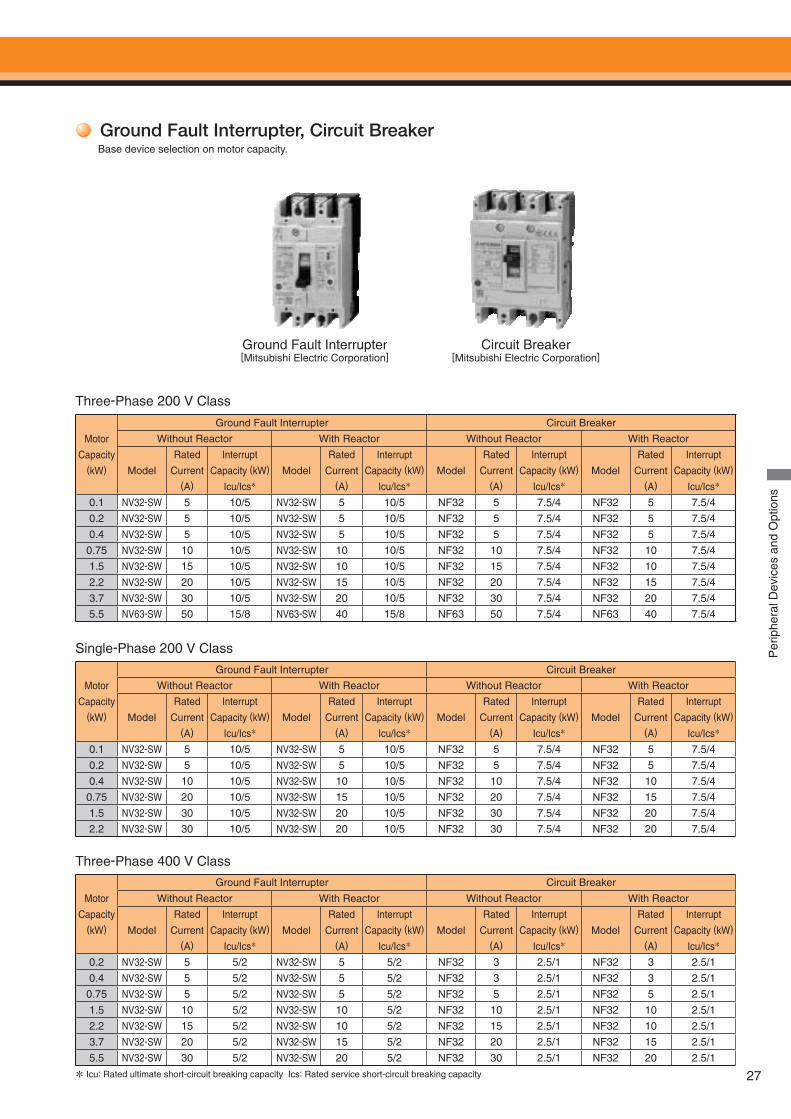
Ground Fault Interrupter, Circuit BreakerBase device selection on motor capacity.
Ground Fault Interrupter[Mitsubishi Electric Corporation]
Three-Phase 200 V Class
Single-Phase 200 V Class
Three-Phase 400 V Class
Circuit Breaker[Mitsubishi Electric Corporation]
Motor
Capacity(kW)
Ground Fault Interrupter Circuit Breaker
Without Reactor With Reactor Without Reactor With Reactor
Model
Rated
Current (A)
Interrupt
Capacity (kW)
Icu/Ics*
Model
Rated
Current (A)
Interrupt
Capacity (kW)
Icu/Ics*
Model
Rated
Current (A)
Interrupt
Capacity (kW)
Icu/Ics*
Model
Rated
Current (A)
Interrupt
Capacity (kW)
Icu/Ics*
0.1 NV32-SW 5 10/5 NV32-SW 5 10/5 NF32 5 7.5/4 NF32 5 7.5/4
0.2 NV32-SW 5 10/5 NV32-SW 5 10/5 NF32 5 7.5/4 NF32 5 7.5/4
0.4 NV32-SW 5 10/5 NV32-SW 5 10/5 NF32 5 7.5/4 NF32 5 7.5/4
0.75 NV32-SW 10 10/5 NV32-SW 10 10/5 NF32 10 7.5/4 NF32 10 7.5/4
1.5 NV32-SW 15 10/5 NV32-SW 10 10/5 NF32 15 7.5/4 NF32 10 7.5/4
2.2 NV32-SW 20 10/5 NV32-SW 15 10/5 NF32 20 7.5/4 NF32 15 7.5/4
3.7 NV32-SW 30 10/5 NV32-SW 20 10/5 NF32 30 7.5/4 NF32 20 7.5/4
5.5 NV63-SW 50 15/8 NV63-SW 40 15/8 NF63 50 7.5/4 NF63 40 7.5/4
Motor
Capacity(kW)
Ground Fault Interrupter Circuit Breaker
Without Reactor With Reactor Without Reactor With Reactor
Model
Rated
Current (A)
Interrupt
Capacity (kW)
Icu/Ics*
Model
Rated
Current (A)
Interrupt
Capacity (kW)
Icu/Ics*
Model
Rated
Current (A)
Interrupt
Capacity (kW)
Icu/Ics*
Model
Rated
Current (A)
Interrupt
Capacity (kW)
Icu/Ics*
0.1 NV32-SW 5 10/5 NV32-SW 5 10/5 NF32 5 7.5/4 NF32 5 7.5/4
0.2 NV32-SW 5 10/5 NV32-SW 5 10/5 NF32 5 7.5/4 NF32 5 7.5/4
0.4 NV32-SW 10 10/5 NV32-SW 10 10/5 NF32 10 7.5/4 NF32 10 7.5/4
0.75 NV32-SW 20 10/5 NV32-SW 15 10/5 NF32 20 7.5/4 NF32 15 7.5/4
1.5 NV32-SW 30 10/5 NV32-SW 20 10/5 NF32 30 7.5/4 NF32 20 7.5/4
2.2 NV32-SW 30 10/5 NV32-SW 20 10/5 NF32 30 7.5/4 NF32 20 7.5/4
Motor
Capacity(kW)
Ground Fault Interrupter Circuit Breaker
Without Reactor With Reactor Without Reactor With Reactor
Model
Rated
Current (A)
Interrupt
Capacity (kW)
Icu/Ics*
Model
Rated
Current (A)
Interrupt
Capacity (kW)
Icu/Ics*
Model
Rated
Current (A)
Interrupt
Capacity (kW)
Icu/Ics*
Model
Rated
Current (A)
Interrupt
Capacity (kW)
Icu/Ics*
0.2 NV32-SW 5 5/2 NV32-SW 5 5/2 NF32 3 2.5/1 NF32 3 2.5/1
0.4 NV32-SW 5 5/2 NV32-SW 5 5/2 NF32 3 2.5/1 NF32 3 2.5/1
0.75 NV32-SW 5 5/2 NV32-SW 5 5/2 NF32 5 2.5/1 NF32 5 2.5/1
1.5 NV32-SW 10 5/2 NV32-SW 10 5/2 NF32 10 2.5/1 NF32 10 2.5/1
2.2 NV32-SW 15 5/2 NV32-SW 10 5/2 NF32 15 2.5/1 NF32 10 2.5/1
3.7 NV32-SW 20 5/2 NV32-SW 15 5/2 NF32 20 2.5/1 NF32 15 2.5/1
5.5 NV32-SW 30 5/2 NV32-SW 20 5/2 NF32 30 2.5/1 NF32 20 2.5/1
* Icu: Rated ultimate short-circuit breaking capacity Ics: Rated service short-circuit breaking capacity
28
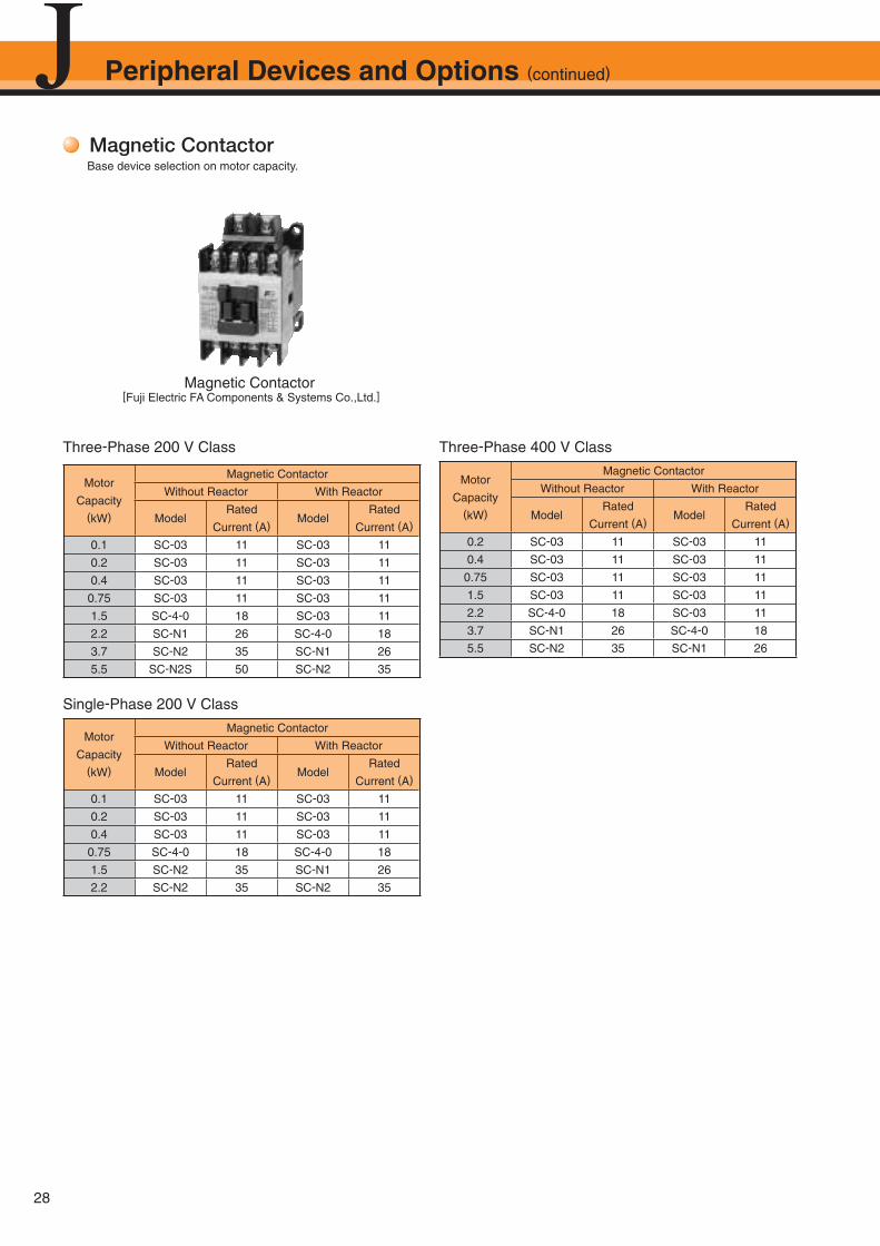
Peripheral Devices and Options (continued)
Magnetic ContactorBase device selection on motor capacity.
Magnetic Contactor [Fuji Electric FA Components & Systems Co.,Ltd.]
Three-Phase 200 V Class
Single-Phase 200 V Class
Three-Phase 400 V Class
Motor
Capacity(kW)
Magnetic Contactor
Without Reactor With Reactor
ModelRated
Current (A)Model
Rated
Current (A)
0.2 SC-03 11 SC-03 11
0.4 SC-03 11 SC-03 11
0.75 SC-03 11 SC-03 11
1.5 SC-03 11 SC-03 11
2.2 SC-4-0 18 SC-03 11
3.7 SC-N1 26 SC-4-0 18
5.5 SC-N2 35 SC-N1 26
Motor
Capacity(kW)
Magnetic Contactor
Without Reactor With Reactor
ModelRated
Current (A)Model
Rated
Current (A)
0.1 SC-03 11 SC-03 11
0.2 SC-03 11 SC-03 11
0.4 SC-03 11 SC-03 11
0.75 SC-4-0 18 SC-4-0 18
1.5 SC-N2 35 SC-N1 26
2.2 SC-N2 35 SC-N2 35
Motor
Capacity(kW)
Magnetic Contactor
Without Reactor With Reactor
ModelRated
Current (A)Model
Rated
Current (A)
0.1 SC-03 11 SC-03 11
0.2 SC-03 11 SC-03 11
0.4 SC-03 11 SC-03 11
0.75 SC-03 11 SC-03 11
1.5 SC-4-0 18 SC-03 11
2.2 SC-N1 26 SC-4-0 18
3.7 SC-N2 35 SC-N1 26
5.5 SC-N2S 50 SC-N2 35
29
Lead 250
Lead 910
Mounting hole specifications2-3 tapped
2-4 Dia.MTG holes
30
2416
36
7
9
22.5
30 16
34
68
76
2633
Model: DCR2-50A22E Model: DCR2-10A25C
[Nippon Chemi-Con Corporation]
Model: RFN3AL504KDWeight: 22 g Weight: 5 g Weight: 150 g
0.8 Dia.4.8 Dia.
18 Dia.
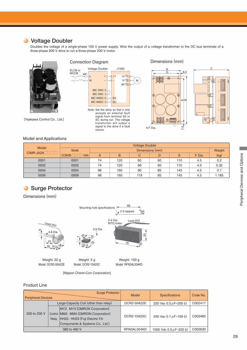
Surge Protector
Product Line
Dimensions (mm)
Surge Protector
Peripheral DevicesModel Specifi cations Code No.
200 to 230 V
Large-Capacity Coil (other than relay) DCR2-50A22E 220 Vac 0.5 μF+200 Ω C002417
Control
Relay
MY2,MY3 [OMRON Corporation]
MM2,MM4 [OMRON Corporation]
HH22,HH23 [Fuji Electric FA
Components & Systems Co., Ltd.]
DCR2-10A25C 250 Vac 0.1 μF+100 Ω C002482
380 to 460 V RFN3AL504KD 1000 Vdc 0.5 μF+220 Ω C002630
Per
iphe
ral D
evic
es a
nd O
ptio
ns
LMC
N
ELCB or MCCB
Voltage Doubler
+−
MC ON(+)
+1−
J1000
MC ON(−)MC ANS(+)MC ANS(−)
S3SC
U/T1V/T2W/T3
M
A CD
4-F Dia.
E7.
5B
6.5
Voltage DoublerDoubles the voltage of a single-phase 100 V power supply. Wire the output of a voltage transformer to the DC bus terminals of a three-phase 200 V drive to run a three-phase 200 V motor.
[Yaskawa Control Co., Ltd.]
Connection Diagram Dimensions (mm)
Model
CIMR-JA2A
Voltage Doubler
Model
CCMVB- -VAA
Dimensions (mm) Weight (kg)A B C D E F Dia.
0001 0001 74 120 60 60 110 4.5 0.2
0002 0002 74 120 68 60 110 4.5 0.32
0004 0004 98 160 90 85 145 4.5 0.7
0006 0006 98 160 119 85 145 4.5 1.185
Model and Applications
Note: Set the drive so that it only accepts an external fault signal from terminal S3 or SC during run. The voltage transformer will output a signal to the drive if a fault occurs.
30
DC Reactor (UZDA-B for DC circuit)Base device selection on motor capacity.
Connection Diagram
Dimensions (mm)
Note: Reactor recommended for power supplies larger than 600 kVA. Use an AC reactor if power supply is 0.2 kW or smaller.
4000
(kVA)600
60 4000
Reactor required
Reactor unnecessary
PowerSupplyCapacity
Drive Capacity (kVA)
J1000
ELCB or MCCB
DC Reactor
R
S
T
R/L1S/L2T/L3
U/T1
U X
V/T2W/T3
M
Note: Remove jumper between +1 and +2, and wire as shown in the diagram.
+2 +1
BX
Connection Lead(1.25 mm2) Nameplate
Nameplate
X
U
B
60G
X
Figure 1 Figure 2
4-MTG holes(1 Dia.)
2-Terminals (2 Dia.)
2-MTG holes(1 Dia.)
Z
ZH
K Y2
Y1
Three-Phase 200 V Class
Three-Phase 400 V Class
* Cable: IV, 75˚C, ambient temperature 45˚C, 3 lines max.
Motor Capacity
(kW)Current
(A)Inductance
(mH)Code No. Figure
Dimensions(mm) Weight
(kg)
Watt Loss(W)
Wire Gauge*(mm2)X Y2 Y1 Z B H K G 1 Dia. 2 Dia.
0.4 5.4 8 X010048 1 85 – – 53 74 – – 32 M4 – 0.8 8 2
0.75 5.4 8 X010048 1 85 – – 53 74 – – 32 M4 – 0.8 8 2
1.5 18 3 X010049 2 86 80 36 76 60 55 18 – M4 M5 2 18 5.5
2.2 18 3 X010049 2 86 80 36 76 60 55 18 – M4 M5 2 18 5.5
3.7 18 3 X010049 2 86 80 36 76 60 55 18 – M4 M5 2 18 5.5
5.5 36 1 X010050 2 105 90 46 93 64 80 26 – M6 M6 3.2 22 8
Motor Capacity
(kW)Current
(A)Inductance
(mH)Code No. Figure
Dimensions(mm) Weight
(kg)
Watt Loss(W)
Wire Gauge*(mm2)X Y2 Y1 Z B H K G 1 Dia. 2 Dia.
0.4 3.2 28 X010052 1 85 – – 53 74 – – 32 M4 – 0.8 9 2
0.75 3.2 28 X010052 1 85 – – 53 74 – – 32 M4 – 0.8 9 2
1.5 5.7 11 X010053 1 90 – – 60 80 – – 32 M4 – 1 11 2
2.2 5.7 11 X010053 1 90 – – 60 80 – – 32 M4 – 1 11 2
3.7 12 6.3 X010054 2 86 80 36 76 60 55 18 – M4 M5 2 16 2
5.5 23 3.6 X010055 2 105 90 46 93 64 80 26 – M6 M5 3.2 27 5.5
Peripheral Devices and Options (continued)
Notes: 1. Inquire for use of a DC reactor with the single-phase input series. 2. Use an AC reactor if power supply is 0.2 kW or smaller.
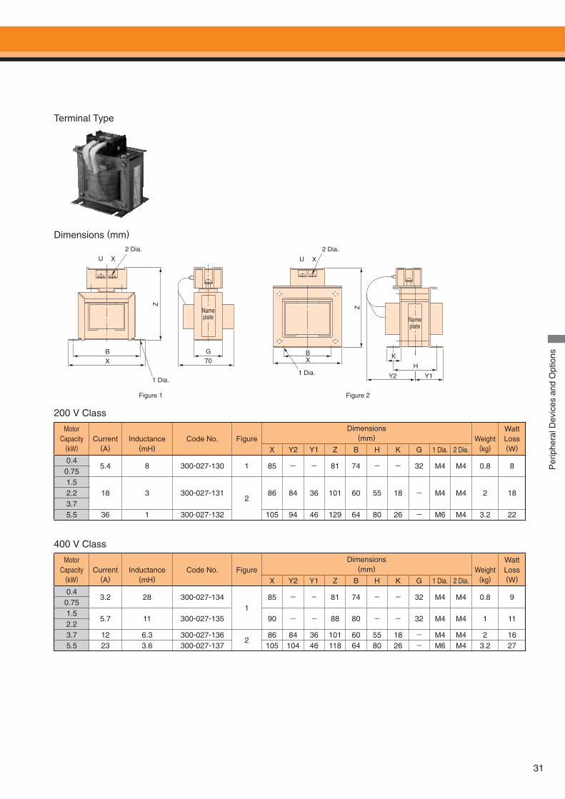
31
Per
iphe
ral D
evic
es a
nd O
ptio
ns
Motor Capacity
(kW)Current
(A)Inductance
(mH)Code No. Figure
Dimensions(mm) Weight
(kg)
WattLoss(W)X Y2 Y1 Z B H K G 1 Dia. 2 Dia.
0.45.4 8 300-027-130 1 85 - - 81 74 - - 32 M4 M4 0.8 8
0.751.5
18 3 300-027-1312
86 84 36 101 60 55 18 - M4 M4 2 182.23.75.5 36 1 300-027-132 105 94 46 129 64 80 26 - M6 M4 3.2 22
Motor Capacity
(kW)Current
(A)Inductance
(mH)Code No. Figure
Dimensions(mm) Weight
(kg)
WattLoss(W)X Y2 Y1 Z B H K G 1 Dia. 2 Dia.
0.43.2 28 300-027-134
185 - - 81 74 - - 32 M4 M4 0.8 9
0.751.5
5.7 11 300-027-135 90 - - 88 80 - - 32 M4 M4 1 112.23.7 12 6.3 300-027-136
286 84 36 101 60 55 18 - M4 M4 2 16
5.5 23 3.6 300-027-137 105 104 46 118 64 80 26 - M6 M4 3.2 27
Terminal Type
B
Z
U X
X
G
70
2 Dia.
1 Dia.
Nameplate
U X
BX
K
Y2 Y1
H
2 Dia.
1 Dia.
Z
Nameplate
200 V Class
400 V Class
Dimensions (mm)
Figure 1 Figure 2
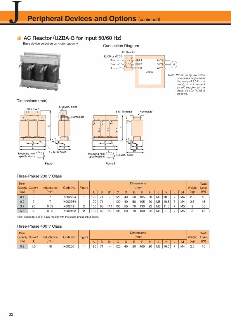
32
AC Reactor (UZBA-B for Input 50/60 Hz)Base device selection on motor capacity.
Dimensions (mm)
Connection Diagram
Three-Phase 200 V Class
Three-Phase 400 V Class
U/T1V/T2W/T3
M
R
S
T
R/L1S/L2T/L3
U
V
W
X
Y
Z
ELCB or MCCB
J1000
AC Reactor
Note: When using low noise type drives (high-carrier frequency of 2.5 kHz or more), do not connect an AC reactor to the output side (U, V, W) of the drive.
D
C
4.5
FA
U X V YWZ
4-J MTG holes
6-M MTG holes
Mounting holespecifications
Nameplate
Nameplate
4-J MTG holes
6-M: Terminal
HEB
K
LMounting holespecifications K
L
U
X
V
Y
W
Z
C
HEB
B1
DFA
Figure 1 Figure 2
4.5
Motor Capacity
(kW)Current
(A)Inductance
(mH)Code No. Figure
Dimensions(mm) Weight
(kg)
Watt Loss(W)A B B1 C D E F H J K L M
0.1 2 7 X002764 1 120 71 – 120 40 50 105 20 M6 10.5 7 M4 2.5 15
0.2 2 7 X002764 1 120 71 – 120 40 50 105 20 M6 10.5 7 M4 2.5 15
3.7 20 0.53 X002491 2 130 88 114 105 50 70 130 22 M6 11.5 7 M5 3 35
5.5 30 0.35 X002492 2 130 88 119 105 50 70 130 22 M6 9 7 M5 3 45
Motor Capacity
(kW)Current
(A)Inductance
(mH)Code No. Figure
Dimensions(mm) Weight
(kg)
Watt Loss(W)A B B1 C D E F H J K L M
0.2 1.3 18 X002561 1 120 71 – 120 40 50 105 20 M6 10.5 7 M4 2.5 15
Peripheral Devices and Options (continued)
Note: Inquire for use of a DC reactor with the single-phase input series.

33
Per
iphe
ral D
evic
es a
nd O
ptio
ns
Figure 1
Terminal Type
Motor Capacity
(kW)Current
(A)Inductance
(mH)Code No. Figure
Dimensions(mm) Weight
(kg)
Watt Loss(W)A B B1 C D E F H J K L M
0.4 2.5 4.2 X002553
1
120 71
-
120 40 50 105 20
M6
10.5
7
M4
2.5 150.75 5 2.1 X002554
1.5 10 1.1 X002489130 88 130 50 70 130 22 11.5 3
25
2.2 15 0.71 X002490 30
3.7 20 0.53 300-027-1202 135 88
140130 50 70 130 22
-7 3
35
5.5 30 0.35 300-027-121 150 9 45
Motor Capacity
(kW)Current
(A)Inductance
(mH)Code No. Figure
Dimensions(mm) Weight
(kg)
Watt Loss(W)A B B1 C D E F H J K L M
0.4 1.3 18 X002561
1
120 71
-
120 40 50 105 20
M6
10.5
7 M4
2.5 150.75 2.5 8.4 X002562
1.5 5 4.2 X002563
13088
130 5070
130 22
93
252.2 7.5 3.6 X002564
3.7 10 2.2 X00250011.5
40
5.5 15 1.42 X002501 98 80 4 50
Figure 2
200 V Class
400 V Class
Dimensions (mm)
D
C4.
5
FA
UXVYWZ6-M MTG holes
Nameplate
HEB
4-J MTG holesMounting holespecifications K
L
M
FD
U X V Y W Z
HEB
B1A
C
4-MTG holes (M6)
Nameplate
L
K(E)
Mounting holespecifications
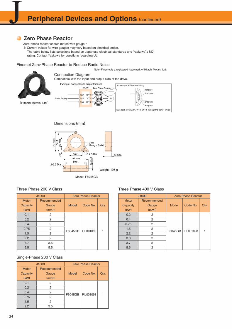
34
Peripheral Devices and Options (continued)
Zero Phase ReactorZero-phase reactor should match wire gauge.*
* Current values for wire gauges may vary based on electrical codes. The table below lists selections based on Japanese electrical standards and Yaskawa’s ND
rating. Contact Yaskawa for questions regarding UL.
Connection DiagramCompatible with the input and output side of the drive.
Dimensions (mm)
Finemet Zero-Phase Reactor to Reduce Radio Noise
Close-upof V/T2-phaseWiring
1st pass
2nd pass
3rd pass
4th pass
Pass each wire (U/T1, V/T2, W/T3) through the core 4 times.
Example: Connection to output terminal
R/L1
Power Supply S/L2
T/L3
U/T1
J1000
V/T2
W/T3
Zero Phase Reactor
M
78 m
ax.
39m
in.
721
71
12.5
0.3
50 1
80 195 max.
26 max.
3-M4Hexagon Socket
Weight: 195 g
Model: F6045GB
3-4.5 Dia.
2-5.5 Dia.
J1000 Zero Phase Reactor
Motor
Capacity(kW)
Recommended
Gauge(mm2)
Model Code No. Qty.
0.1 2
F6045GB FIL001098 1
0.2 2
0.4 2
0.75 2
1.5 2
2.2 2
3.7 3.5
5.5 5.5
J1000 Zero Phase Reactor
Motor
Capacity(kW)
Recommended
Gauge(mm2)
Model Code No. Qty.
0.2 2
F6045GB FIL001098 1
0.4 2
0.75 2
1.5 2
2.2 2
3.0 2
3.7 2
5.5 2
J1000 Zero Phase Reactor
Motor
Capacity(kW)
Recommended
Gauge(mm2)
Model Code No. Qty.
0.1 2
F6045GB FIL001098 1
0.2 2
0.4 2
0.75 2
1.5 2
2.2 3.5
Three-Phase 200 V Class
Single-Phase 200 V Class
Three-Phase 400 V Class
Note: Finemet is a registered trademark of Hitachi Metals, Ltd.
[Hitachi Metals, Ltd.]
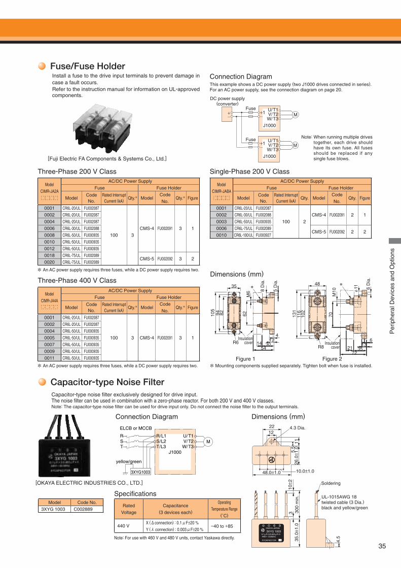
35
Capacitor-type Noise Filter
Dimensions (mm)Connection Diagram
Model Code No.
3XYG 1003 C002889Rated
Voltage
Capacitance (3 devices each)
Operating
Temperature Range(˚C)
440 VX (Δconnection) : 0.1μF±20 %
Y (λ connection) : 0.003μF±20 %−40 to +85
Specifi cations
Capacitor-type noise fi lter exclusively designed for drive input.The noise fi lter can be used in combination with a zero-phase reactor. For both 200 V and 400 V classes.Note: The capacitor-type noise fi lter can be used for drive input only. Do not connect the noise fi lter to the output terminals.
J1000
ELCB or MCCB
RST
R/L1S/L2T/L3
yellow/green
3XYG1003
U/T1V/T2W/T3
M
22
Soldering
5.5
4.5
3 300
min
.11
26.0
± 1.0
10± 2
35.0
± 1.0
48.0±1.0 10.0±1.0
124.3 Dia.
UL-1015AWG 18 twisted cable (3 Dia.)black and yellow/green
OKAYA JAPAN
3XYG 1003
440V~50/60Hz
XYCAPACITOR
0.1 F×3/0.003 F×3μ μ
1 2 3
-4
[OKAYA ELECTRIC INDUSTRIES CO., LTD.]
Note: For use with 460 V and 480 V units, contact Yaskawa directly.
Dimensions (mm)
35 *
R6 14 3054
124
Insulationcover
105
94 82 62M
6 8 D
ia.
5 D
ia.
48
R8
*
Insulationcover
613
21 3572
131
116
102
M10
70
φ11 6
Dia
.
Per
iphe
ral D
evic
es a
nd O
ptio
ns
Fuse/Fuse Holder Install a fuse to the drive input terminals to prevent damage in
case a fault occurs. Refer to the instruction manual for information on UL-approved components.
[Fuji Electric FA Components & Systems Co., Ltd.]
Model
CIMR-JA4A
AC/DC Power Supply
Fuse Fuse Holder
ModelCode No.
Rated Interrupt Current (kA) Qty.* Model
Code
No.Qty.* Figure
0001 CR6L-20/UL FU002087
100 3 CMS-4 FU002091 3 1
0002 CR6L-20/UL FU0020870004 CR6L-50/UL FU0009350005 CR6L-50/UL FU0009350007 CR6L-50/UL FU0009350009 CR6L-50/UL FU0009350011 CR6L-50/UL FU000935
Three-Phase 200 V Class Single-Phase 200 V Class
Three-Phase 400 V Class
Model
CIMR-JA2A
AC/DC Power Supply
Fuse Fuse Holder
ModelCode No.
Rated Interrupt Current (kA) Qty.* Model
Code
No.Qty.* Figure
0001 CR6L-20/UL FU002087
100 3CMS-4 FU002091 3 1
0002 CR6L-20/UL FU0020870004 CR6L-20/UL FU0020870006 CR6L-30/UL FU0020880008 CR6L-50/UL FU0009350010 CR6L-50/UL FU0009350012 CR6L-50/UL FU0009350018 CR6L-75/UL FU002089
CMS-5 FU002092 3 20020 CR6L-75/UL FU002089
Model
CIMR-JABA
AC/DC Power Supply
Fuse Fuse Holder
ModelCode No.
Rated Interrupt Current (kA) Qty. Model
Code
No.Qty. Figure
0001 CR6L-20/UL FU002087
100 2CMS-4 FU002091 2 10002 CR6L-30/UL FU002088
0003 CR6L-50/UL FU0009350006 CR6L-75/UL FU002089
CMS-5 FU002092 2 20010 CR6L-100/UL FU000927
* Mounting components supplied separately. Tighten bolt when fuse is installed.Figure 1 Figure 2
This example shows a DC power supply (two J1000 drives connected in series).For an AC power supply, see the connection diagram on page 20.
Note: When running multiple drives together, each drive should have its own fuse. All fuses should be replaced if any single fuse blows.
* An AC power supply requires three fuses, while a DC power supply requires two.
* An AC power supply requires three fuses, while a DC power supply requires two.
Connection Diagram
M
M
W/T3J1000
V/T2U/T1
1+_
W/T3J1000
V/T2U/T1
1+_+_
Fuse
Fuse
DC power supply(converter)
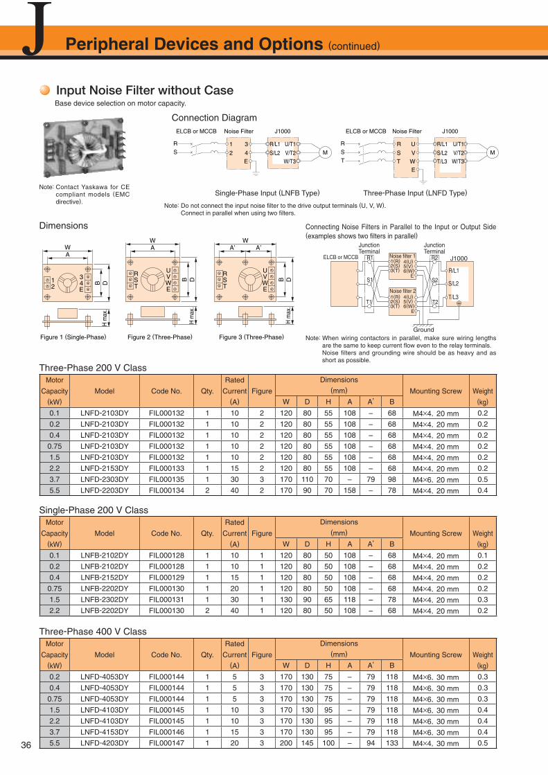
36
Peripheral Devices and Options (continued)
Input Noise Filter without CaseBase device selection on motor capacity.
Dimensions
Connection Diagram
Three-Phase 200 V Class
Single-Phase 200 V Class
Three-Phase 400 V Class
M
R/L1
S/L2
1
2
U/T1
V/T2W/T3
3
4E
R
S
ELCB or MCCB Noise Filter J1000 Noise Filter J1000
M
R/L1
S/L2T/L3
R
S
U/T1
V/T2W/T3
U
V
E
R
S
T WT
ELCB or MCCB
Note: Do not connect the input noise fi lter to the drive output terminals (U, V, W). Connect in parallel when using two fi lters.
Single-Phase Input (LNFB Type) Three-Phase Input (LNFD Type)
12
34E
WA
ST
VR U
WE
WA
ST
VR U
WE
WA’A’
Figure 1 (Single-Phase) Figure 2 (Three-Phase) Figure 3 (Three-Phase)
DBDBDBH
max
.
H m
ax.
H m
ax.
Motor
Capacity(kW)
Model Code No. Qty.
Rated
Current (A)
Figure
Dimensions(mm) Mounting Screw Weight
(kg)W D H A A’ B
0.1 LNFD-2103DY FIL000132 1 10 2 120 80 55 108 – 68 M4×4,20 mm 0.2
0.2 LNFD-2103DY FIL000132 1 10 2 120 80 55 108 – 68 M4×4,20 mm 0.2
0.4 LNFD-2103DY FIL000132 1 10 2 120 80 55 108 – 68 M4×4,20 mm 0.2
0.75 LNFD-2103DY FIL000132 1 10 2 120 80 55 108 – 68 M4×4,20 mm 0.2
1.5 LNFD-2103DY FIL000132 1 10 2 120 80 55 108 – 68 M4×4,20 mm 0.2
2.2 LNFD-2153DY FIL000133 1 15 2 120 80 55 108 – 68 M4×4,20 mm 0.2
3.7 LNFD-2303DY FIL000135 1 30 3 170 110 70 – 79 98 M4×6,20 mm 0.5
5.5 LNFD-2203DY FIL000134 2 40 2 170 90 70 158 – 78 M4×4,20 mm 0.4
Motor
Capacity(kW)
Model Code No. Qty.
Rated
Current (A)
Figure
Dimensions(mm) Mounting Screw Weight
(kg)W D H A A’ B
0.1 LNFB-2102DY FIL000128 1 10 1 120 80 50 108 – 68 M4×4,20 mm 0.1
0.2 LNFB-2102DY FIL000128 1 10 1 120 80 50 108 – 68 M4×4,20 mm 0.2
0.4 LNFB-2152DY FIL000129 1 15 1 120 80 50 108 – 68 M4×4,20 mm 0.2
0.75 LNFB-2202DY FIL000130 1 20 1 120 80 50 108 – 68 M4×4,20 mm 0.2
1.5 LNFB-2302DY FIL000131 1 30 1 130 90 65 118 – 78 M4×4,20 mm 0.3
2.2 LNFB-2202DY FIL000130 2 40 1 120 80 50 108 – 68 M4×4,20 mm 0.2
Motor
Capacity(kW)
Model Code No. Qty.
Rated
Current (A)
Figure
Dimensions(mm) Mounting Screw Weight
(kg)W D H A A’ B
0.2 LNFD-4053DY FIL000144 1 5 3 170 130 75 – 79 118 M4×6,30 mm 0.3
0.4 LNFD-4053DY FIL000144 1 5 3 170 130 75 – 79 118 M4×6,30 mm 0.3
0.75 LNFD-4053DY FIL000144 1 5 3 170 130 75 – 79 118 M4×6,30 mm 0.3
1.5 LNFD-4103DY FIL000145 1 10 3 170 130 95 – 79 118 M4×6,30 mm 0.4
2.2 LNFD-4103DY FIL000145 1 10 3 170 130 95 – 79 118 M4×6,30 mm 0.4
3.7 LNFD-4153DY FIL000146 1 15 3 170 130 95 – 79 118 M4×6,30 mm 0.4
5.5 LNFD-4203DY FIL000147 1 20 3 200 145 100 – 94 133 M4×4,30 mm 0.5
Note: Contact Yaskawa for CE compliant models (EMC directive).
Note: When wiring contactors in parallel, make sure wiring lengths are the same to keep current fl ow even to the relay terminals.
Noise filters and grounding wire should be as heavy and as short as possible.
Ground
J1000Noise filter 1
Noise filter 2
E
E
R1
S1
T1 T2
R2
S2
R/L1
S/L2
T/L3
1(R)2(S)3(T)
4(U)5(V)6(W)
1(R)2(S)3(T)
4(U)5(V)6(W)
ELCB or MCCB
JunctionTerminal
JunctionTerminal
Connecting Noise Filters in Parallel to the Input or Output Side (examples shows two fi lters in parallel)
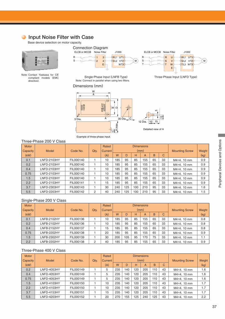
37
Input Noise Filter with CaseBase device selection on motor capacity.
Connection Diagram
Dimensions (mm)
Three-Phase 200 V Class
Note: Connect in parallel when using two fi lters.Single-Phase Input (LNFB Type) Three-Phase Input (LNFD Type)
Note: Contact Yaskawa for CE compliant models (EMC directive).
Single-Phase 200 V Class
Three-Phase 400 V Class
M
R/L1
S/L2
1
2
U/T1
V/T2W/T3
3
4E
R
S
ELCB or MCCB Noise Filter J1000 Noise Filter J1000
M
R/L1
S/L2T/L3
R
S
U/T1
V/T2W/T3
U
V
E
R
S
T WT
ELCB or MCCB
WA
5
15
RST
UV
E
A
W
C10 15
CB D
H m
ax.
Detailed view of A
Example of three-phase input.
5 Dia. 30 Dia.12 Dia.
Motor
Capacity(kW)
Model Code No. Qty.
Rated
Current (A)
Dimensions(mm) Mounting Screw Weight
(kg)W D H A B C
0.1 LNFD-2103HY FIL000140 1 10 185 95 85 155 65 33 M4×4,10 mm 0.9
0.2 LNFD-2103HY FIL000140 1 10 185 95 85 155 65 33 M4×4,10 mm 0.9
0.4 LNFD-2103HY FIL000140 1 10 185 95 85 155 65 33 M4×4,10 mm 0.9
0.75 LNFD-2103HY FIL000140 1 10 185 95 85 155 65 33 M4×4,10 mm 0.9
1.5 LNFD-2103HY FIL000140 1 10 185 95 85 155 65 33 M4×4,10 mm 0.9
2.2 LNFD-2153HY FIL000141 1 15 185 95 85 155 65 33 M4×4,10 mm 0.9
3.7 LNFD-2303HY FIL000143 1 30 240 125 100 210 95 33 M4×4,10 mm 1.6
5.5 LNFD-2203HY FIL000142 2 40 240 125 100 210 95 33 M4×4,10 mm 1.5
Motor
Capacity(kW)
Model Code No. Qty.
Rated
Current (A)
Dimensions(mm) Mounting Screw Weight
(kg)W D H A B C
0.1 LNFB-2102HY FIL000136 1 10 185 95 85 155 65 33 M4×4,10 mm 0.8
0.2 LNFB-2102HY FIL000136 1 10 185 95 85 155 65 33 M4×4,10 mm 0.8
0.4 LNFB-2152HY FIL000137 1 15 185 95 85 155 65 33 M4×4,10 mm 0.8
0.75 LNFB-2202HY FIL000138 1 20 185 95 85 155 65 33 M4×4,10 mm 0.9
1.5 LNFB-2302HY FIL000139 1 30 200 105 95 170 75 33 M4×4,10 mm 1.1
2.2 LNFB-2202HY FIL000138 2 40 185 95 85 155 65 33 M4×4,10 mm 0.9
Motor
Capacity(kW)
Model Code No. Qty.
Rated
Current (A)
Dimensions(mm) Mounting Screw Weight
(kg)W D H A B C
0.2 LNFD-4053HY FIL000149 1 5 235 140 120 205 110 43 M4×4,10 mm 1.6
0.4 LNFD-4053HY FIL000149 1 5 235 140 120 205 110 43 M4×4,10 mm 1.6
0.75 LNFD-4053HY FIL000149 1 5 235 140 120 205 110 43 M4×4,10 mm 1.6
1.5 LNFD-4103HY FIL000150 1 10 235 140 120 205 110 43 M4×4,10 mm 1.7
2.2 LNFD-4103HY FIL000150 1 10 235 140 120 205 110 43 M4×4,10 mm 1.7
3.7 LNFD-4153HY FIL000151 1 15 235 140 120 205 110 43 M4×4,10 mm 1.7
5.5 LNFD-4203HY FIL000152 1 20 270 155 125 240 125 43 M4×4,10 mm 2.2
Per
iphe
ral D
evic
es a
nd O
ptio
ns
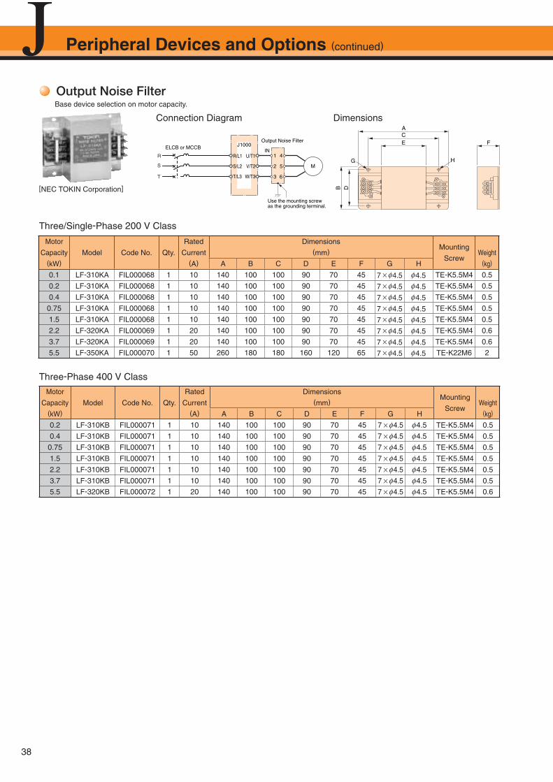
38
Peripheral Devices and Options (continued)
Output Noise FilterBase device selection on motor capacity.
Connection Diagram
Three/Single-Phase 200 V Class
[NEC TOKIN Corporation]
R
S
T
J1000Output Noise Filter
INR/L1
S/L2
T/L3
U/T1
V/T2
W/T3
ELCB or MCCB
1
2
3
4
5
6
M
Use the mounting screwas the grounding terminal.
E
G
FCA
B D
H
Dimensions
Three-Phase 400 V Class
Motor
Capacity(kW)
Model Code No. Qty.
Rated
Current (A)
Dimensions(mm)
Mounting
ScrewWeight
(kg)A B C D E F G H
0.1 LF-310KA FIL000068 1 10 140 100 100 90 70 45 7 × φ4.5 φ4.5 TE-K5.5M4 0.5
0.2 LF-310KA FIL000068 1 10 140 100 100 90 70 45 7 × φ4.5 φ4.5 TE-K5.5M4 0.5
0.4 LF-310KA FIL000068 1 10 140 100 100 90 70 45 7 × φ4.5 φ4.5 TE-K5.5M4 0.5
0.75 LF-310KA FIL000068 1 10 140 100 100 90 70 45 7 × φ4.5 φ4.5 TE-K5.5M4 0.5
1.5 LF-310KA FIL000068 1 10 140 100 100 90 70 45 7 × φ4.5 φ4.5 TE-K5.5M4 0.5
2.2 LF-320KA FIL000069 1 20 140 100 100 90 70 45 7 × φ4.5 φ4.5 TE-K5.5M4 0.6
3.7 LF-320KA FIL000069 1 20 140 100 100 90 70 45 7 × φ4.5 φ4.5 TE-K5.5M4 0.6
5.5 LF-350KA FIL000070 1 50 260 180 180 160 120 65 7 × φ4.5 φ4.5 TE-K22M6 2
Motor
Capacity(kW)
Model Code No. Qty.
Rated
Current (A)
Dimensions(mm)
Mounting
ScrewWeight
(kg)A B C D E F G H
0.2 LF-310KB FIL000071 1 10 140 100 100 90 70 45 7 × φ4.5 φ4.5 TE-K5.5M4 0.5
0.4 LF-310KB FIL000071 1 10 140 100 100 90 70 45 7 × φ4.5 φ4.5 TE-K5.5M4 0.5
0.75 LF-310KB FIL000071 1 10 140 100 100 90 70 45 7 × φ4.5 φ4.5 TE-K5.5M4 0.5
1.5 LF-310KB FIL000071 1 10 140 100 100 90 70 45 7 × φ4.5 φ4.5 TE-K5.5M4 0.5
2.2 LF-310KB FIL000071 1 10 140 100 100 90 70 45 7 × φ4.5 φ4.5 TE-K5.5M4 0.5
3.7 LF-310KB FIL000071 1 10 140 100 100 90 70 45 7 × φ4.5 φ4.5 TE-K5.5M4 0.5
5.5 LF-320KB FIL000072 1 20 140 100 100 90 70 45 7 × φ4.5 φ4.5 TE-K5.5M4 0.6
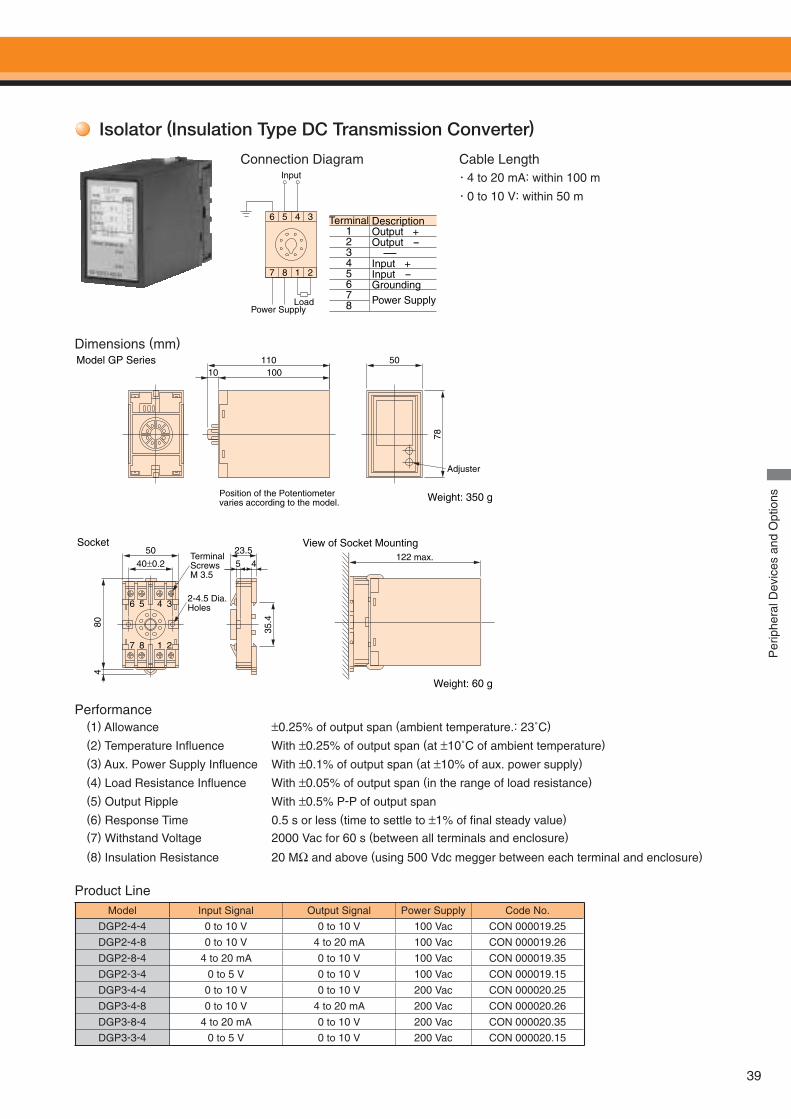
39
Isolator (Insulation Type DC Transmission Converter)
Dimensions (mm)
Connection Diagram Cable Length・4 to 20 mA: within 100 m
・0 to 10 V: within 50 m
Performance
Product Line
(1) Allowance ±0.25% of output span (ambient temperature.: 23˚C)
(2) Temperature Infl uence With ±0.25% of output span (at ±10˚C of ambient temperature)
(3) Aux. Power Supply Infl uence With ±0.1% of output span (at ±10% of aux. power supply)
(4) Load Resistance Infl uence With ±0.05% of output span (in the range of load resistance)
(5) Output Ripple With ±0.5% P-P of output span(6) Response Time 0.5 s or less (time to settle to ±1% of fi nal steady value)
(7) Withstand Voltage 2000 Vac for 60 s (between all terminals and enclosure)
(8) Insulation Resistance 20 MΩ and above (using 500 Vdc megger between each terminal and enclosure)
Model Input Signal Output Signal Power Supply Code No.
DGP2-4-4 0 to 10 V 0 to 10 V 100 Vac CON 000019.25
DGP2-4-8 0 to 10 V 4 to 20 mA 100 Vac CON 000019.26
DGP2-8-4 4 to 20 mA 0 to 10 V 100 Vac CON 000019.35
DGP2-3-4 0 to 5 V 0 to 10 V 100 Vac CON 000019.15
DGP3-4-4 0 to 10 V 0 to 10 V 200 Vac CON 000020.25
DGP3-4-8 0 to 10 V 4 to 20 mA 200 Vac CON 000020.26
DGP3-8-4 4 to 20 mA 0 to 10 V 200 Vac CON 000020.35
DGP3-3-4 0 to 5 V 0 to 10 V 200 Vac CON 000020.15
10010110 50
Adjuster
TerminalScrewsM 3.5
50
80
78
35.4
4
122 max.40 0.2
6 5 4 3
7 8 1 2
23.5
5 4
Model GP Series
Socket View of Socket Mounting
Position of the Potentiometervaries according to the model.
2-4.5 Dia.Holes
Weight: 350 g
Weight: 60 g
3456
2187
Power Supply
Input
Load
Terminal12345678
DescriptionOutput +Output - -Input +Input -Grounding
Power Supply
Per
iphe
ral D
evic
es a
nd O
ptio
ns
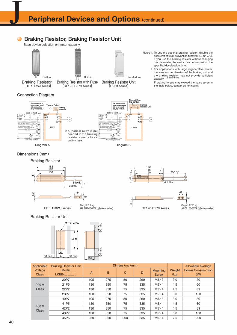
40
C
D B
150A 30 min. 15
0m
in.
150
min
.
30 min.
MTG Screw
Peripheral Devices and Options (continued)
Braking Resistor, Braking Resistor UnitBase device selection on motor capacity.
Braking Resistor
170150
44
250 55 0.5
51.
2
13
182
Braking Resistor Unit
Weight: 0.2 kg(All ERF-150WJ Series models)
ApplicableVoltageClass
Braking Resistor UnitModel
LKEB-
Dimensions (mm)
Weight(kg)
Allowable AveragePower Consumption
(W)A B C DMounting
Screw
200 VClass
20P7 105 275 50 260 M5×3 3.0 30
21P5 130 350 75 335 M5×4 4.5 60
22P2 130 350 75 335 M5×4 4.5 89
23P7 130 350 75 335 M5×4 5.0 150
400 VClass
40P7 105 275 50 260 M5×3 3.0 30
41P5 130 350 75 335 M5×4 4.5 60
42P2 130 350 75 335 M5×4 4.5 89
43P7 130 350 75 335 M5×4 5.0 150
45P5 250 350 200 335 M6×4 7.5 220
ERF-150WJ series
42
20
250
182165150
1
2
45
3
1.2
284.
2
4.2 Dia.
WARNING SURFACERISK OF BURN
B1
B2
+15−0
CF120-B579 seriesWeight: 0.256 kg(All CF120-B579 Series models)
Notes: 1. To use the optional braking resistor, disable the deceleration stall prevention function (L3-04 = 0). If you use the braking resistor without changing this parameter, the motor may not stop within the specifi ed deceleration time.
2. For applications with large regenerative power, the standard combination of the braking unit and the braking resistor may not provide sufficient capacity.
If braking torque may exceed the value given in the table below, contact us for inquiry.
Braking Resistor Unit[LKEB series]
Braking Resistor[ERF-150WJ series]
Diagram A Diagram B
U/T1V/T2W/T3
R/L1MC
S/L2T/L3 M
B2B1
P B1 2
RST
ELCB or MCCB
Thermal RelayTrip Contact
BrakingResistor Unit
3-phasePowerSupply
Use sequencer tobreak power supplyside on overloadrelay trip contact.
J1000
U/T1V/T2W/T3
R/L1MC
S/L2T/L3 M
B2B1RST
ELCB or MCCB
Thermal Relay*BrakingResistor
3-phasePowerSupply
Use sequencer tobreak power supplyside on overloadrelay trip contact.*
J1000
ONOFFTHRX
SA
1 2
TRX
MC MA
MC
TRX
Fault relay contact
Braking resistor unitThermal relay trip contact
MC
SA
SA
THRX
2MCCBMC MBONOFFTHRX
SA
1 2
TRX
MC MA
MC
TRX
Fault relay contact
Braking resistor unitThermal relay trip contact
MC
SA
SA
THRX
2MCCBMC MB
Braking Resistor with Fuse[CF120-B579 series]
* A thermal relay is not needed if the braking resistor already has a built-in fuse.
Connection Diagram
Dimensions (mm)
Built-in Stand-aloneBuilt-in Stand-alone
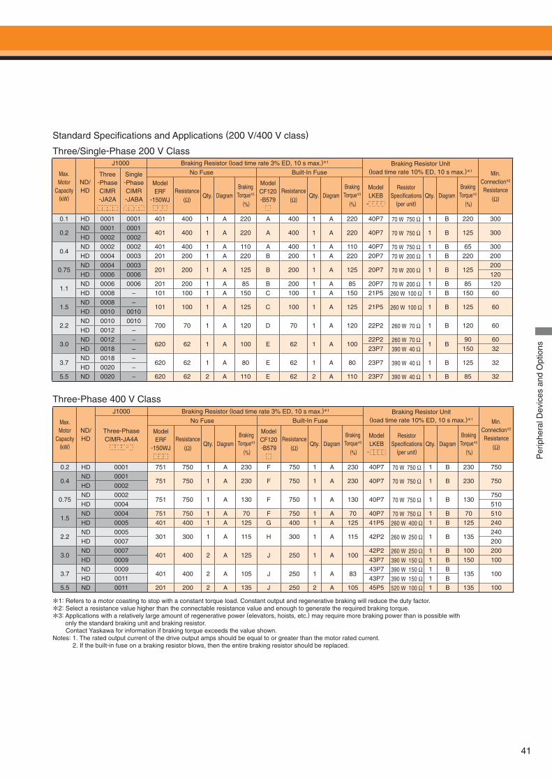
41
Per
iphe
ral D
evic
es a
nd O
ptio
ns
Max. Motor
Capacity(kW)
ND/HD
J1000 Braking Resistor (load time rate 3% ED, 10 s max.)*1 Braking Resistor Unit(load time rate 10% ED, 10 s max.)*1 Min.
Connection*2
Resistance(Ω)
Three-PhaseCIMR-JA2A
Single-PhaseCIMR-JABA
No Fuse Built-In Fuse
ModelERF
-150WJResistance
(Ω)Qty. Diagram
Braking Torque*3
(%)
ModelCF120-B579
Resistance(Ω)
Qty. DiagramBraking Torque*3
(%)
ModelLKEB
-
ResistorSpecifi cations
(per unit)Qty. Diagram
Braking Torque*3
(%)
0.1 HD 0001 0001 401 400 1 A 220 A 400 1 A 220 40P7 70 W 750 Ω 1 B 220 300
0.2ND 0001 0001
401 400 1 A 220 A 400 1 A 220 40P7 70 W 750 Ω 1 B 125 300HD 0002 0002
0.4ND 0002 0002 401 400 1 A 110 A 400 1 A 110 40P7 70 W 750 Ω 1 B 65 300
HD 0004 0003 201 200 1 A 220 B 200 1 A 220 20P7 70 W 200 Ω 1 B 220 200
0.75ND 0004 0003
201 200 1 A 125 B 200 1 A 125 20P7 70 W 200 Ω 1 B 125200
HD 0006 0006 120
1.1ND 0006 0006 201 200 1 A 85 B 200 1 A 85 20P7 70 W 200 Ω 1 B 85 120
HD 0008 – 101 100 1 A 150 C 100 1 A 150 21P5 260 W 100 Ω 1 B 150 60
1.5ND 0008 –
101 100 1 A 125 C 100 1 A 125 21P5 260 W 100 Ω 1 B 125 60HD 0010 0010
2.2ND 0010 0010
700 70 1 A 120 D 70 1 A 120 22P2 260 W 70 Ω 1 B 120 60HD 0012 –
3.0 ND 0012 –
620 62 1 A 100 E 62 1 A 10022P2 260 W 70 Ω
1 B90 60
HD 0018 – 23P7 390 W 40 Ω 150 32
3.7ND 0018 –
620 62 1 A 80 E 62 1 A 80 23P7 390 W 40 Ω 1 B 125 32HD 0020 –
5.5 ND 0020 – 620 62 2 A 110 E 62 2 A 110 23P7 390 W 40 Ω 1 B 85 32
Standard Specifi cations and Applications (200 V/400 V class)
Three/Single-Phase 200 V Class
Three-Phase 400 V Class
Max. Motor
Capacity(kW)
ND/HD
J1000 Braking Resistor (load time rate 3% ED, 10 s max.)*1 Braking Resistor Unit(load time rate 10% ED, 10 s max.)*1 Min.
Connection*2
Resistance(Ω)
Three-PhaseCIMR-JA4A
No Fuse Built-In Fuse
ModelERF
-150WJResistance
(Ω)Qty. Diagram
Braking Torque*3
(%)
ModelCF120-B579
Resistance(Ω)
Qty. DiagramBraking Torque*3
(%)
ModelLKEB
-
ResistorSpecifi cations
(per unit)Qty. Diagram
Braking Torque*3
(%)
0.2 HD 0001 751 750 1 A 230 F 750 1 A 230 40P7 70 W 750 Ω 1 B 230 750
0.4ND 0001
751 750 1 A 230 F 750 1 A 230 40P7 70 W 750 Ω 1 B 230 750HD 0002
0.75ND 0002
751 750 1 A 130 F 750 1 A 130 40P7 70 W 750 Ω 1 B 130750
HD 0004 510
1.5ND 0004 751 750 1 A 70 F 750 1 A 70 40P7 70 W 750 Ω 1 B 70 510
HD 0005 401 400 1 A 125 G 400 1 A 125 41P5 260 W 400 Ω 1 B 125 240
2.2ND 0005
301 300 1 A 115 H 300 1 A 115 42P2 260 W 250 Ω 1 B 135240
HD 0007 200
3.0 ND 0007
401 400 2 A 125 J 250 1 A 10042P2 260 W 250 Ω 1 B 100 200
HD 0009 43P7 390 W 150 Ω 1 B 150 100
3.7ND 0009
401 400 2 A 105 J 250 1 A 8343P7 390 W 150 Ω 1 B
135 100HD 0011 43P7 390 W 150 Ω 1 B
5.5 ND 0011 201 200 2 A 135 J 250 2 A 105 45P5 520 W 100 Ω 1 B 135 100
*1: Refers to a motor coasting to stop with a constant torque load. Constant output and regenerative braking will reduce the duty factor.
*2: Select a resistance value higher than the connectable resistance value and enough to generate the required braking torque.
*3: Applications with a relatively large amount of regenerative power (elevators, hoists, etc.) may require more braking power than is possible with only the standard braking unit and braking resistor.
Contact Yaskawa for information if braking torque exceeds the value shown.Notes: 1. The rated output current of the drive output amps should be equal to or greater than the motor rated current. 2. If the built-in fuse on a braking resistor blows, then the entire braking resistor should be replaced.
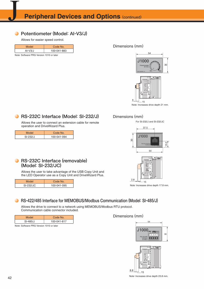
42
Peripheral Devices and Options (continued)
Potentiometer (Model: AI-V3/J)Allows for easier speed control.
Model Code No.
AI-V3/J 100-041-883
Note: Increases drive depth 21 mm.
Potentiometer
Min MaxNPJT42392-1-0
AI-V3/J
J100030
54
615
Dimensions (mm)
Note: Software PRG Version 1010 or later
RS-422/485 Interface for MEMOBUS/Modbus Communication (Model: SI-485/J)Allows the drive to connect to a network using MEMOBUS/Modbus RTU protocol.Communication cable connector included.
Model Code No.
SI-485/J 100-041-817
Note: Increases drive depth 23.8 mm.
S− S+ IG R− R+RS-422/485
InterfaceSI-485/J
J100030
54
8.815
Dimensions (mm)
Note: Software PRG Version 1010 or later
RS-232C Interface (Model: SI-232/J)Allows the user to connect an extension cable for remote operation and DriveWizard Plus.
Model Code No.
SI-232/J 100-041-094
RS-232C Interface (removable) (Model: SI-232/JC)Allows the user to take advantage of the USB Copy Unit and the LED Operator use as a Copy Unit and DriveWizard Plus.
Model Code No.
SI-232/JC 100-041-095
37.5
54
30
13.2
Dimensions (mm)For SI-232/J and SI-232/JC
2.815
Note: Increases drive depth 17.8 mm.
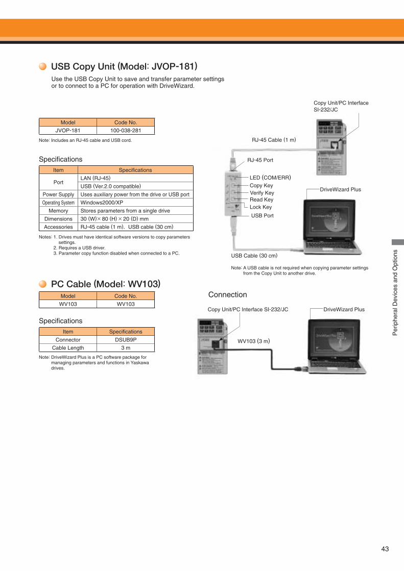
43
Per
iphe
ral D
evic
es a
nd O
ptio
ns
Note: A USB cable is not required when copying parameter settings from the Copy Unit to another drive.
USB Copy Unit (Model: JVOP-181)
Model Code No.
JVOP-181 100-038-281
Item Specifi cations
PortLAN (RJ-45)
USB (Ver.2.0 compatible)
Power Supply Uses auxiliary power from the drive or USB port
Operating System Windows2000/XP
Memory Stores parameters from a single drive
Dimensions 30 (W)× 80 (H) × 20 (D) mm
Accessories RJ-45 cable (1 m),USB cable (30 cm)
Note: Includes an RJ-45 cable and USB cord.
Specifi cations
Notes: 1. Drives must have identical software versions to copy parameters settings.
2. Requires a USB driver. 3. Parameter copy function disabled when connected to a PC.
Use the USB Copy Unit to save and transfer parameter settings or to connect to a PC for operation with DriveWizard.
RJ-45 Cable (1 m)
USB Cable (30 cm)
DriveWizard Plus
LED (COM/ERR)Copy KeyVerify KeyRead Key
USB Port
RJ-45 Port
Lock Key
Copy Unit/PC Interface SI-232/JC
PC Cable (Model: WV103)Model Code No.
WV103 WV103
Specifi cations
Item Specifi cations
Connector DSUB9P
Cable Length 3 m
Note: DriveWizard Plus is a PC software package for managing parameters and functions in Yaskawa drives.
WV103 (3 m)
DriveWizard Plus
Connection
Copy Unit/PC Interface SI-232/JC
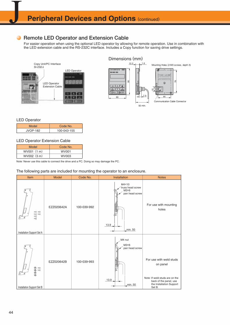
44
Peripheral Devices and Options (continued)
Remote LED Operator and Extension CableFor easier operation when using the optional LED operator by allowing for remote operation. Use in combination with the LED extension cable and the RS-232C interface. Includes a Copy function for saving drive settings.
Dimensions (mm)
S / N : J007XE273710001
90
15
78
60 44 7.9
50 min.
Communication Cable Connector
12.2 1.6Mounting Holes (2-M3 screws, depth 5)
LED Operator
Model Code No.
JVOP-182 100-043-155
LED Operator Extension Cable
Model Code No.
WV001(1 m) WV001
WV002(3 m) WV003
The following parts are included for mounting the operator to an enclosure.
Item Model Code No. Installation Notes
Installation Support Set A
EZZ020642A 100-039-992For use with mounting
holes
Installation Support Set B
EZZ020642B 100-039-993For use with weld studs
on panel
Note: If weld studs are on the back of the panel, use the Installation Support Set B.
13.9
min. 50
M4×10 truss head screw
M3×6 pan head screw
13.9
min. 50
M3×6 pan head screw
M4 nut
LED Operator
Copy Unit/PC Interface SI-232/J
LED Operator Extension Cable
Note: Never use this cable to connect the drive and a PC. Doing so may damage the PC.

45
Frequency Meter/Current MeterDimensions (mm)
Note: DCF-6A is 3 V, 1 mA, 3 kΩ. For J1000 multi-function analog monitor output, set frequency potentiometer or parameter H4-02 (multi-function analog output termi-nal AM gain) within 0 to 3 V (default is 0 to 10 V).
Weight: 0.3 kgPanel Drilling Plan
52 D
ia. 24
24
2424
2424
60
2424123012.5
0.5 10
65
53
4-4 Dia.
2-M4 Terminal Screws4-M3 MTG Bolts
Model Code No.
Scale-75 Hz full-scale: DCF-6A FM000065Scale-60/120 Hz full-scale: DCF-6A FM000085
Scale-5 A full-scale: DCF-6A DCF-6A-5A
Scale-10 A full-scale: DCF-6A DCF-6A-10A
Scale-20 A full-scale: DCF-6A DCF-6A-20A
Scale-30 A full-scale: DCF-6A DCF-6A-30A
Scale-50 A full-scale: DCF-6A DCF-6A-50A
Frequency Setting Potentiometer/Frequency Meter Adjusting PotentiometerDimensions (mm)
Control Dial for Frequency Setting Potentiometer/Frequency Meter Adjusting PotentiometerDimensions (mm)
Meter Plate for Frequency Setting Potentiometer/Frequency Meter Adjusting PotentiometerDimensions (mm)
Model Code No.
RV30YN20S 2 kΩ RH000739RV30YN20S 20 kΩ RH000850
Panel Drilling Plan
1 2
60˚
3
10 120 1
302
Dia
.
M9 P 0.75
12
1225
6 D
ia.
0 0.1
17.51.5
Weight: 0.2 kg
10 Dia.
4.5 Dia.
2.8 0.2 Dia.2.5 1
Model Code No.
CM-3S HLNZ-0036
29.923
32.826.1
16.1
15 7.5
3.4
Shaft6 Dia.
Model Code No.
NPJT41561-1 NPJT41561-1
0
1
3
4 6
7
9
10
45
45
12
3.6 Dia.9.5 Dia.
Per
iphe
ral D
evic
es a
nd O
ptio
ns
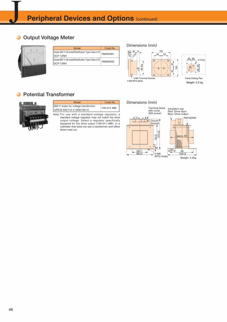
46
Output Voltage Meter
Model Code No.
Scale-300 V full-scale(Rectifi cation Type Class 2.5):
SCF-12NHVM000481
Scale-600 V full-scale(Rectifi cation Type Class 2.5):
SCF-12NHVM000502
Weight: 0.3 kg
Panel Drilling Plan
85 D
ia.
4535
4535
5050
100
5050123012.5
0.5 10
120
87
4-5 Dia.
2-M4 Terminal Screws4-M3 MTG Bolts
Dimensions (mm)
Potential TransformerModel Code No.
600 V meter for voltage transformer:
UPN-B 440/110 V (400/100 V)100-011-486
Dimensions (mm)
Note: For use with a standard voltage regulator, a standard voltage regulator may not match the drive output voltage. Select a regulator specifically designed for the drive output (100-011-486), or a voltmeter that does not use a transformer and offers direct read out.
Peripheral Devices and Options (continued)
Weight: 2.2kg
Insulation cap Red: Drive inputBlue: Drive output
4-M6MTG Holes
102±2
31 9086±256±1
Nameplate
101±
276
± 21.
6
Ground terminal
Terminal block with cover(M3 screw)
U V u v E
approx. 85
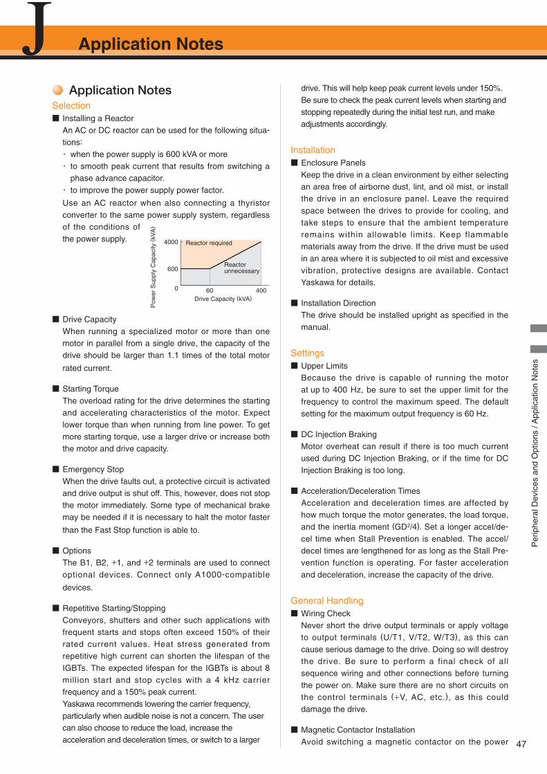
Application Notes
47
適用上のご注意Application NotesSelection■ Installing a Reactor
An AC or DC reactor can be used for the following situa-
tions:
・ when the power supply is 600 kVA or more・ to smooth peak current that results from switching a
phase advance capacitor. ・ to improve the power supply power factor.
Use an AC reactor when also connecting a thyristor converter to the same power supply system, regardless of the conditions of the power supply.
■ Drive CapacityWhen running a specialized motor or more than one motor in parallel from a single drive, the capacity of the drive should be larger than 1.1 times of the total motor
rated current.
■ Starting TorqueThe overload rating for the drive determines the starting and accelerating characteristics of the motor. Expect lower torque than when running from line power. To get more starting torque, use a larger drive or increase both the motor and drive capacity.
■ Emergency StopWhen the drive faults out, a protective circuit is activated and drive output is shut off. This, however, does not stop the motor immediately. Some type of mechanical brake may be needed if it is necessary to halt the motor faster
than the Fast Stop function is able to.
■ OptionsThe B1, B2, +1, and +2 terminals are used to connect optional devices. Connect only A1000-compatible
devices.
■ Repetitive Starting/StoppingConveyors, shutters and other such applications with frequent starts and stops often exceed 150% of their rated current values. Heat stress generated from repetitive high current can shorten the lifespan of the IGBTs. The expected lifespan for the IGBTs is about 8 million start and stop cycles with a 4 kHz carrier frequency and a 150% peak current.Yaskawa recommends lowering the carrier frequency, particularly when audible noise is not a concern. The user can also choose to reduce the load, increase the acceleration and deceleration times, or switch to a larger
drive. This will help keep peak current levels under 150%. Be sure to check the peak current levels when starting and stopping repeatedly during the initial test run, and make adjustments accordingly.
Installation■ Enclosure Panels
Keep the drive in a clean environment by either selecting an area free of airborne dust, lint, and oil mist, or install the drive in an enclosure panel. Leave the required space between the drives to provide for cooling, and take steps to ensure that the ambient temperature remains within allowable limits. Keep flammable materials away from the drive. If the drive must be used in an area where it is subjected to oil mist and excessive vibration, protective designs are available. Contact Yaskawa for details.
■ Installation DirectionThe drive should be installed upright as specifi ed in the manual.
Settings■ Upper Limits
Because the drive is capable of running the motor at up to 400 Hz, be sure to set the upper limit for the frequency to control the maximum speed. The default setting for the maximum output frequency is 60 Hz.
■ DC Injection BrakingMotor overheat can result if there is too much current used during DC Injection Braking, or if the time for DC Injection Braking is too long.
■ Acceleration/Deceleration TimesAcceleration and deceleration times are affected by how much torque the motor generates, the load torque, and the inertia moment (GD2/4). Set a longer accel/de-
cel time when Stall Prevention is enabled. The accel/decel times are lengthened for as long as the Stall Pre-
vention function is operating. For faster acceleration and deceleration, increase the capacity of the drive.
General Handling■ Wiring Check
Never short the drive output terminals or apply voltage to output terminals (U/T1, V/T2, W/T3), as this can cause serious damage to the drive. Doing so will destroy the drive. Be sure to perform a final check of all sequence wiring and other connections before turning the power on. Make sure there are no short circuits on the control terminals (+V, AC, etc.), as this could damage the drive.
■ Magnetic Contactor InstallationAvoid switching a magnetic contactor on the power
4000
600
0 60 400Drive Capacity (kVA)
Pow
er S
uppl
y C
apac
ity (
kVA
)
Reactor required
Reactor unnecessary
Per
iphe
ral D
evic
es a
nd O
ptio
ns /
App
licat
ion
Not
es
Application Notes (continued)
48
supply side more frequently than once every 30 minutes. Frequent switching can cause damage to the
drive.
■ Inspection and MaintenanceAfter shutting off the drive, make sure the CHARGE light has gone out completely before preforming any inspection or maintenance. Residual voltage in drive capacitors can cause serious electric shock.The heatsink can become quite hot during operation, and proper precautions should be taken to prevent burns. When replacing the cooling fan, shut off the power and wait at least 15 minutes to be sure that the
heatsink has cooled down.
■ Transporting the DriveNever steam clean the drive.During transport, keep the drive from coming into contact with salts, fluorine, bromine and other such harmful chemicals.
Peripheral Devices■ Installing an MCCB
Install an MCCB or a ground fault interrupter recom-
mended by Yaskawa to the power supply side of the drive to protect internal circuitry. The type of MCCB needed depends on the power supply power factor (power supply voltage, output frequency, load charac-
teristics, etc.). Sometimes a fairly large MCCB may be required due to the affects of harmonic current on op-
erating characteristics. Those using a ground fault in-
terrupter other than those recommended in this cata-
log, use one fi tted for harmonic suppression measures (one designed specifi cally for drives). The rated current of the ground fault interrupter must be 200 mA or high-
er per drive unit.
Select an MCCB with a rated capacity greater than the
short-circuit current for the power supply. For a fairly
large power supply transformer, a fuse can be added to
the ground fault interrupter or MCCB in order to handle
the short-circuit current level.
■ Magnetic Contactor for Input PowerUse a magnetic contactor (MC) to ensure that power to the drive can be completely shut off when necessary. The MC should be wired so that it opens when a fault output terminal is triggered. Even though an MC is designed to switch following a momentary power loss, frequent MC use can damage other components. Avoid switching the MC more than once every 30 minutes. The MC will not be activated after a momentary power loss if using the operator keypad to run the drive. This is because the drive is unable to restart automatically when set for LOCAL. Although the drive can be
stopped by using an MC installed on the power supply side, the drive cannot stop the motor in a controlled fashion, and it will simply coast to stop. If a braking resistor or dynamic braking unit has been installed, be sure to set up a sequence that opens the MC with a thermal protector switch connected to the braking
resistor device.
■ Magnetic Contactor for MotorAs a general principle, the user should avoid opening and closing the magnetic contactor between the motor and the drive during run. Doing so can cause high peak currents and overcurrent faults. If magnetic contactors are used to bypass the drive by connecting the motor to the power supply directly, make sure to close the bypass only after the drive is stopped and fully disconnected from the motor. The Speed Search function should be used to start a coasting motor.Use an MC with delayed release if momentary power
loss is a concern.
■ Motor Thermal Over Load Relay InstallationAlthough the drive comes with built in electrothermal protection to prevent damage from overheat, a thermal relay should be connected between the drive and each motor if running several motors from the same drive. For a multipole motor or some other type of non-standard motor, Yaskawa recommends using an external thermal relay appropriate for the motor. Be sure to disable the motor protection selection parameter (L1-01 = 0), and set the thermal relay or thermal protection value to 1.1 times the motor rated current listed on the motor nameplate.
■ Improving the Power FactorInstalling a DC or AC reactor to the input side of the drive can help improve the power factor. Refrain from using a capacitor or surge absorber on the output side as a way of improving the power factor, because harmonic contents on the output side can lead to damage from overheat. This can also lead to problems with overcurrent.
■ Radio Frequency InterferenceDrive output contains harmonic contents that can affect the performance of surrounding electronic instruments such as an AM radio. These problems can be prevented by installing a noise fi lter, as well as by using a properly grounded metal conduit to separate wiring between the drive and motor.
■ Wire Gauges and Wiring DistanceMotor torque can suffer as a result of voltage loss across a long cable running between the drive and motor, especially when there is low frequency output. Make sure that a large enough wire gauge is used.The optional LED operator requires a proprietary cable
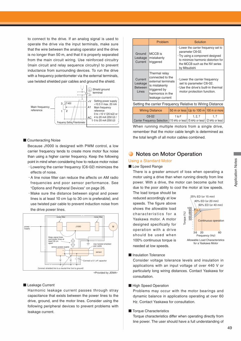
49
to connect to the drive. If an analog signal is used to operate the drive via the input terminals, make sure that the wire between the analog operator and the drive is no longer than 50 m, and that it is properly separated from the main circuit wiring. Use reinforced circuitry (main circuit and relay sequence circuitry) to prevent inductance from surrounding devices. To run the drive with a frequency potentiometer via the external terminals,
use twisted shielded pair cables and ground the shield.
■ Counteracting Noise
Because J1000 is designed with PWM control, a low carrier frequency tends to create more motor flux noise than using a higher carrier frequency. Keep the following point in mind when considering how to reduce motor noise:
û Lowering the carrier frequency (C6-02) minimizes the effects of noise.
û A line noise fi lter can reduce the affects on AM radio frequencies and poor sensor performance. See “Options and Peripheral Devices” on page 26.
û Make sure the distance between signal and power lines is at least 10 cm (up to 30 cm is preferable), and use twisted pair cable to prevent induction noise from
the drive power lines.
Connect a 0.1 µF capacitor
Keep signal lines and power lines at least 30 cm apart
noise filter
power supply
sensor power supply
Connect shielded line to a neutral line (not to ground)
M
Use twisted shielded pair cable
noise filter
J1000
+−
sensor
<Provided by JEMA>
■ Leakage CurrentHarmonic leakage current passes through stray capacitance that exists between the power lines to the drive, ground, and the motor lines. Consider using the following peripheral devices to prevent problems with
leakage current.
Problem Solution
Ground Leakage Current
MCCB is mistakenly triggered
û Lower the carrier frequency set to parameter C6-02.
û Try using a component designed to minimize harmonic distortion for the MCCB such as the NV series by Mitsubishi
Current Leakage Between
Lines
Thermal relay connected to the external terminals is mistakenly triggered by harmonics in the leakage current
û Lower the carrier frequency set to parameter C6-02.
û Use the drive's built-in thermal motor protection function.
Setting the carrier Frequency Relative to Wiring Distance
Wiring Distance 50 m or less Up to 100 m 100 m or more
C6-02:Carrier Frequency Selection
1 to F(15 kHz or less)
1, 2, 7(5 kHz or less)
1, 7(2 kHz or less)
When running multiple motors from a single drive, remember that the motor cable length is determined as
the total length of all motor cables combined.
Notes on Motor OperationUsing a Standard Motor■ Low Speed Range
There is a greater amount of loss when operating a motor using a drive than when running directly from line power. With a drive, the motor can become quite hot due to the poor ability to cool the motor at low speeds. The load torque should be reduced accordingly at low speeds. The figure above shows the allowable load c h a r a c t e r i s t i c s f o r a Yaskawa motor. A motor designed specifically for operat ion wi th a dr ive shou ld be used when 100% continuous torque is
needed at low speeds.
■ Insulation ToleranceConsider voltage tolerance levels and insulation in applications with an input voltage of over 440 V or particularly long wiring distances. Contact Yaskawa for
consultation.
■ High Speed OperationProblems may occur with the motor bearings and dynamic balance in applications operating at over 60
Hz. Contact Yaskawa for consultation.
■ Torque CharacteristicsTorque characteristics differ when operating directly from line power. The user should have a full understanding of
Shield groundterminal
Main frequencyreference
Setting power supply +10.5 V max. 20 mAMain frequency reference0 to +10 V (20 kΩ) or4 to 20 mA (250 Ω) /0 to 20 mA (250 Ω)
Frequency Setting Potentiometer
+V
A1
AC
g p(default)
2 kΩ
2
3
1
App
licat
ion
Not
es
50
3 6 20 60
60708090
100
25% ED (or 15 min)
40% ED (or 20 min)
60% ED (or 40 min)
Allowable Load Characteristics for a Yaskawa Motor
Frequency (Hz)
Continuous operation
Torq
ue (
%)
Application Notes (continued)
50
the load torque characteristics for the application.
■ Vibration and ShockJ1000 lets the user choose between high carrier PWM control and low carrier PWM. Selecting high carrier PWM can help reduce motor oscillation. Keep the following points in mind when using high carrier PWM:(1) Resonance
Take particular caution when using a variable speed drive for an application that is conventionally run from line power at a constant speed. Shock-
absorbing rubber should be installed around the base of the motor and the Jump Frequency selection should be enabled to prevent resonance.
(2) Any imperfection on a rotating body increases vibration with speed.Caution should be taken when operating above the
motor rated speed.
■ Audible NoiseNoise created during run varies by the carrier frequency setting. Using a high carrier frequency creates about as much noise as running from line power. Operating above the rated speed (i.e., above 60 Hz), however, can
create unpleasant motor noise.
Applications with Specialized Motors
■ Multi-pole MotorBecause the rated current will differ from a standard motor, be sure to check the maximum current when selecting a drive. Always stop the motor before switching between the number of motor poles. If a regenerative overvoltage fault occurs or if overcurrent
protection is triggered, the motor will coast to stop.
■ Submersible MotorBecause motor rated current is greater than a standard motor, select the drive capacity accordingly. Be sure to use a large enough motor cable to avoid decreasing the maximum torque level on account of voltage drop
caused by a long motor cable.
■ Explosion-proof MotorBoth the motor and drive need to be tested together to be certified as explosion-proof. The drive is not for
explosion proof areas.
■ Geared MotorContinuous operation specifications dif fer by the manufacturer of the lubricant. Due to potential problems of gear damage when operating at low speeds, be sure to select the proper lubr icant. Consult with the
manufacturer for applications that require speeds greater than the rated speed range of the motor or gear
box.
■ Synchronous MotorStarting current and rated current are higher for syn-
chronous motors than for standard motors. Contact Yas-
kawa for the best drive selection when operating a syn-
chronous motor.
■ Single-phase MotorVariable speed drives are not designed for operating single phase motors. Using a capacitor to start the motor causes excessive current to f low into the capacitors, potentially causing damage. A split-phase start or a repulsion start can end up burning out the starter coils because the internal centrifugal switch is not activated. J1000 is for use only with 3-phase motors.
■ Uras VibratorUras vibrator is a vibration motor that gets power from centrifugal force by rotating unbalanced weights on b o t h e n d s o f t h e s h a f t . M a ke t h e f o l l ow i n g considerations when selecting a drive for use with an Uras vibrator:(1) Uras vibrator should be used within the drive rated
frequency(2) Increase the acceleration time five to fifteen times
longer than would normally be used due to the high amount of load inertia of an Uras vibratorNote: Contact Yaskawa for applications that require an
acceleration time of less than 5 s.
(3) Drive may have trouble starting due to undertorque that results from erratic torque (static friction torque at start)
■ Motor with BrakeCaution should be taken when using a drive to operate a motor with a built-in holding brake. If the brake is connected to the output side of the drive, it may not release at start due to low voltage levels. A separate power supply should be installed for the motor brake. Motors with a built-in brake tend to generate a fair
amount of noise when running at low speeds.
Power Driven Machinery (decelerators, belts, chains, etc.)Continuous operation at low speeds wears on the lubricating material used in gear box type systems to accelerate and decelerate power driven machinery. Caution should also be taken when operating at speeds above the rated machine speed due to noise and shortened performance life.
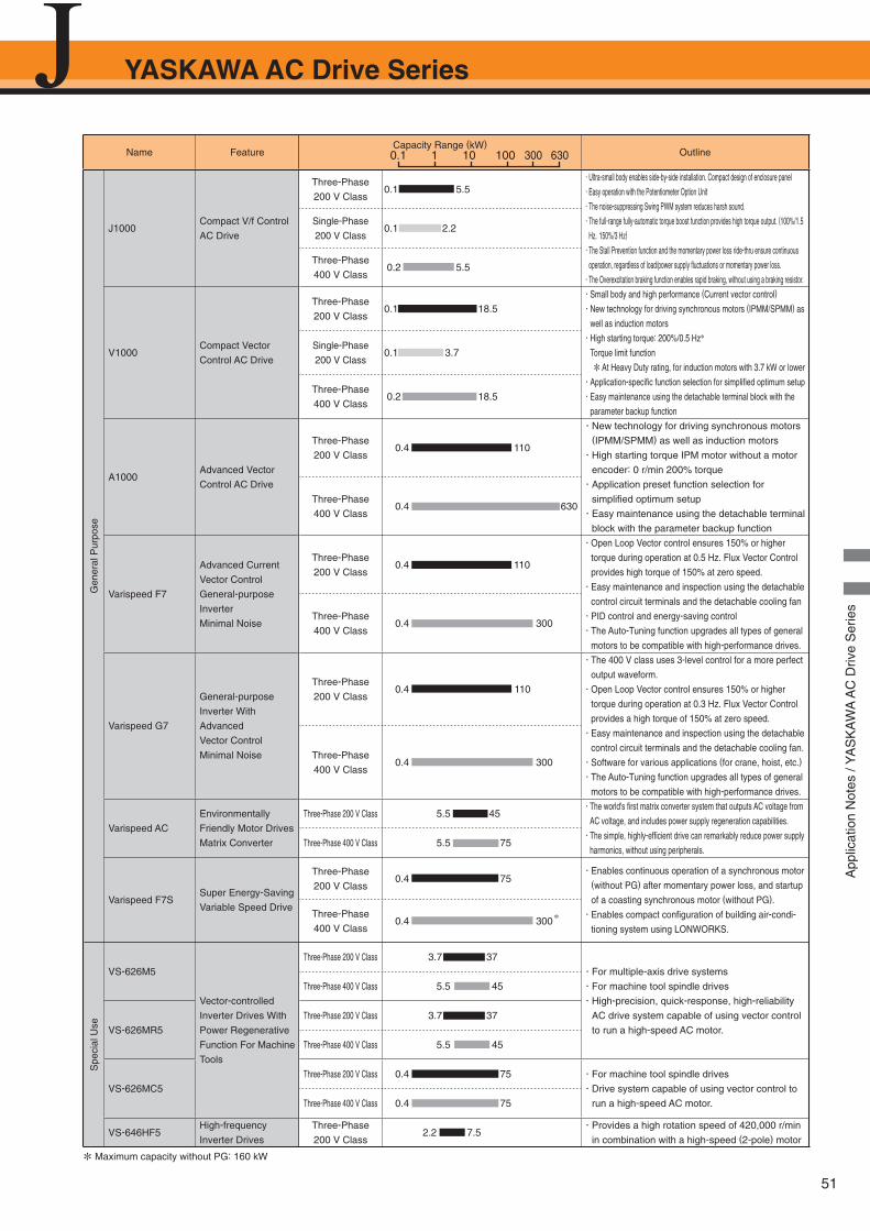
51
YASKAWA AC Drive Series
App
licat
ion
Not
es /
YA
SK
AW
A A
C D
rive
Ser
ies
Name FeatureCapacity Range (kW)
Outline
Gen
eral
Pur
pose
J1000Compact V/f Control
AC Drive
Three-Phase
200 V Class0.1 5.5
・ Ultra-small body enables side-by-side installation. Compact design of enclosure panel
・ Easy operation with the Potentiometer Option Unit
・ The noise-suppressing Swing PWM system reduces harsh sound.
・ The full-range fully-automatic torque boost function provides high torque output. (100%/1.5
Hz,150%/3 Hz)
・ The Stall Prevention function and the momentary power loss ride-thru ensure continuous
operation, regardless of load/power supply fl uctuations or momentary power loss.
・ The Overexcitation braking function enables rapid braking, without using a braking resistor.
Single-Phase
200 V Class0.1 2.2
Three-Phase
400 V Class 0.2 5.5
V1000Compact Vector
Control AC Drive
Three-Phase
200 V Class0.1 18.5
・ Small body and high performance (Current vector control)
・ New technology for driving synchronous motors (IPMM/SPMM) as
well as induction motors
・ High starting torque: 200%/0.5 Hz*
Torque limit function
* At Heavy Duty rating, for induction motors with 3.7 kW or lower
・ Application-specifi c function selection for simplifi ed optimum setup
・ Easy maintenance using the detachable terminal block with the
parameter backup function
Single-Phase
200 V Class0.1 3.7
Three-Phase
400 V Class 0.2 18.5
A1000Advanced Vector
Control AC Drive
Three-Phase
200 V Class 0.4 110
・ New technology for driving synchronous motors (IPMM/SPMM) as well as induction motors
・ High starting torque IPM motor without a motor
encoder: 0 r/min 200% torque
・ Application preset function selection for
simplifi ed optimum setup
・ Easy maintenance using the detachable terminal
block with the parameter backup function
Three-Phase
400 V Class 0.4 630
Varispeed F7
Advanced Current
Vector Control
General-purpose
Inverter
Minimal Noise
Three-Phase
200 V Class 0.4 110
・ Open Loop Vector control ensures 150% or higher
torque during operation at 0.5 Hz. Flux Vector Control
provides high torque of 150% at zero speed.
・ Easy maintenance and inspection using the detachable
control circuit terminals and the detachable cooling fan
・ PID control and energy-saving control
・ The Auto-Tuning function upgrades all types of general
motors to be compatible with high-performance drives.
Three-Phase
400 V Class 0.4 300
Varispeed G7
General-purpose
Inverter With
Advanced
Vector Control
Minimal Noise
Three-Phase
200 V Class 0.4 110
・ The 400 V class uses 3-level control for a more perfect
output waveform.
・ Open Loop Vector control ensures 150% or higher
torque during operation at 0.3 Hz. Flux Vector Control
provides a high torque of 150% at zero speed.
・ Easy maintenance and inspection using the detachable
control circuit terminals and the detachable cooling fan.
・ Software for various applications (for crane, hoist, etc.)
・ The Auto-Tuning function upgrades all types of general
motors to be compatible with high-performance drives.
Three-Phase
400 V Class 0.4 300
Varispeed AC
Environmentally
Friendly Motor Drives
Matrix Converter
Three-Phase 200 V Class 5.5 45・ The world's fi rst matrix converter system that outputs AC voltage from
AC voltage, and includes power supply regeneration capabilities.
・ The simple, highly-effi cient drive can remarkably reduce power supply
harmonics, without using peripherals.Three-Phase 400 V Class 5.5 75
Varispeed F7SSuper Energy-Saving
Variable Speed Drive
Three-Phase
200 V Class 0.4 75
・ Enables continuous operation of a synchronous motor (without PG) after momentary power loss, and startup
of a coasting synchronous motor (without PG).
・ Enables compact confi guration of building air-condi-
tioning system using LONWORKS.
Three-Phase
400 V Class 0.4 300 *
Spe
cial
Use
VS-626M5
Vector-controlled
Inverter Drives With
Power Regenerative
Function For Machine
Tools
Three-Phase 200 V Class 3.7 37・ For multiple-axis drive systems
・ For machine tool spindle drives
・ High-precision, quick-response, high-reliability
AC drive system capable of using vector control
to run a high-speed AC motor.
Three-Phase 400 V Class 5.5 45
VS-626MR5Three-Phase 200 V Class 3.7 37
Three-Phase 400 V Class 5.5 45
VS-626MC5Three-Phase 200 V Class 0.4 75 ・ For machine tool spindle drives
・ Drive system capable of using vector control to
run a high-speed AC motor.Three-Phase 400 V Class 0.4 75
VS-646HF5High-frequency
Inverter Drives
Three-Phase
200 V Class 2.2 7.5
・ Provides a high rotation speed of 420,000 r/min
in combination with a high-speed (2-pole) motor
* Maximum capacity without PG: 160 kW
0.1 1 10 100 300 630
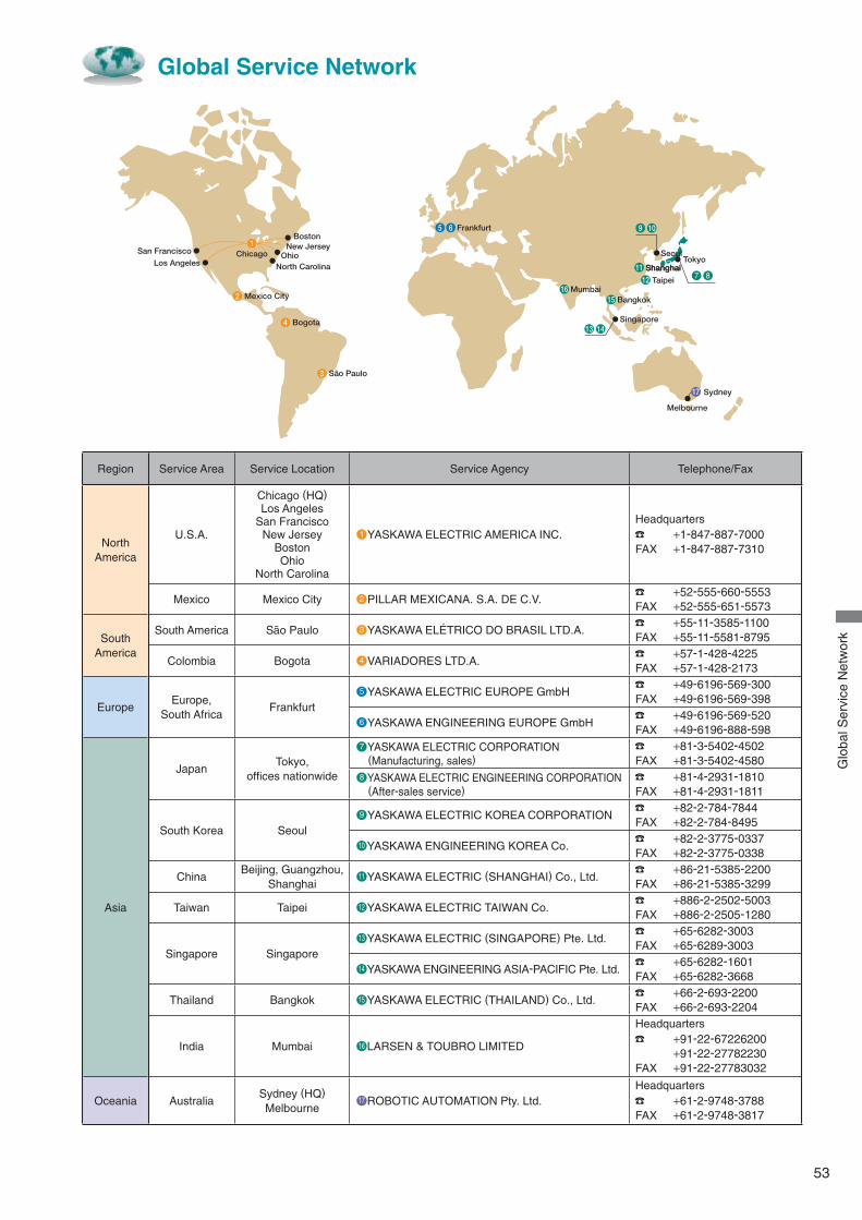
53
Global Service Network
Shanghai
17
ChicagoSan Francisco
BostonFrankfurt
Mumbai
Singapore
Bangkok
SeoulTokyo
Shanghai
Taipei
Sydney
Melbourne
North Carolina
Mexico City
Bogota
Sao Paulo
New JerseyOhio
Los Angeles
1
4
3
65 9
11
12
1516
13 14
10
2
7 8
Region Service Area Service Location Service Agency Telephone/Fax
North America
U.S.A.
Chicago (HQ)Los Angeles
San FranciscoNew Jersey
BostonOhio
North Carolina
●1 YASKAWA ELECTRIC AMERICA INC.Headquarters
+1-847-887-7000FAX +1-847-887-7310
Mexico Mexico City ●2 PILLAR MEXICANA. S.A. DE C.V. +52-555-660-5553
FAX +52-555-651-5573
SouthAmerica
South America Sao Paulo ●3 YASKAWA ELÉTRICO DO BRASIL LTD.A. +55-11-3585-1100
FAX +55-11-5581-8795
Colombia Bogota ●4 VARIADORES LTD.A. +57-1-428-4225
FAX +57-1-428-2173
EuropeEurope,
South AfricaFrankfurt
●5 YASKAWA ELECTRIC EUROPE GmbH +49-6196-569-300
FAX +49-6196-569-398
●6 YASKAWA ENGINEERING EUROPE GmbH +49-6196-569-520
FAX +49-6196-888-598
Asia
JapanTokyo,
offi ces nationwide
●7 YASKAWA ELECTRIC CORPORATION (Manufacturing, sales)
+81-3-5402-4502FAX +81-3-5402-4580
●8 YASKAWA ELECTRIC ENGINEERING CORPORATION (After-sales service)
+81-4-2931-1810FAX +81-4-2931-1811
South Korea Seoul●9 YASKAWA ELECTRIC KOREA CORPORATION
+82-2-784-7844FAX +82-2-784-8495
●10 YASKAWA ENGINEERING KOREA Co. +82-2-3775-0337
FAX +82-2-3775-0338
ChinaBeijing, Guangzhou,
Shanghai●11 YASKAWA ELECTRIC (SHANGHAI) Co., Ltd.
+86-21-5385-2200FAX +86-21-5385-3299
Taiwan Taipei ●12 YASKAWA ELECTRIC TAIWAN Co. +886-2-2502-5003
FAX +886-2-2505-1280
Singapore Singapore●13 YASKAWA ELECTRIC (SINGAPORE) Pte. Ltd.
+65-6282-3003FAX +65-6289-3003
●14 YASKAWA ENGINEERING ASIA-PACIFIC Pte. Ltd. +65-6282-1601
FAX +65-6282-3668
Thailand Bangkok ●15 YASKAWA ELECTRIC (THAILAND) Co., Ltd. +66-2-693-2200
FAX +66-2-693-2204
India Mumbai ●16 LARSEN & TOUBRO LIMITED
Headquarters +91-22-67226200
+91-22-27782230FAX +91-22-27783032
Oceania AustraliaSydney (HQ)Melbourne
●17 ROBOTIC AUTOMATION Pty. Ltd.Headquarters
+61-2-9748-3788FAX +61-2-9748-3817
Glo
bal S
ervi
ce N
etw
ork
In the event that the end user of this product is to be the military and said product is to be employed in any weapons systems or the manufacture thereof, the export will fall under the relevant regulations as stipulated in the Foreign Exchange and Foreign Trade Regulations. Therefore, be sure to follow all procedures and submit all relevant documentation according to any and all rules, regulations and laws that may apply.
Specifications are subject to change without notice for ongoing product modifications and improvements.
© 2008-2010 YASKAWA ELECTRIC CORPORATION. All rights reserved.Printed on 100% recycled paperwith soybean oil ink.
LITERATURE NO. KAEP C710606 24C
10-3-3Published in Japan May 2010 08-3
IRUMA BUSINESS CENTER (SOLUTION CENTER)480, Kamifujisawa, Iruma, Saitama 358-8555, JapanPhone: 81-4-2962-5696 Fax: 81-4-2962-6138
YASKAWA ELECTRIC CORPORATIONNew Pier Takeshiba South Tower, 1-16-1, Kaigan, Minatoku, Tokyo, 105-6891, JapanPhone: 81-3-5402-4511 Fax: 81-3-5402-4580http://www.yaskawa.co.jp
YASKAWA ELECTRIC AMERICA, INC.2121 Norman Drive South, Waukegan, IL 60085, U.S.A.Phone: (800) YASKAWA (800-927-5292) or 1-847-887-7000 Fax: 1-847-887-7310http://www.yaskawa.com
YASKAWA ELETRICO DO BRASIL COMERCIO LTDA.Avenda Fagundes Filho, 620 Bairro Saude, Sao Paulo, SP04304-000, BrasilPhone: 55-11-3585-1100 Fax: 55-11-5581-8795http://www.yaskawa.com.br
YASKAWA ELECTRIC EUROPE GmbHHauptstraβe 185, 65760 Eschborn, GermanyPhone: 49-6196-569-300 Fax: 49-6196-569-398
YASKAWA ELECTRIC UK LTD.1 Hunt Hill Orchardton Woods, Cumbernauld, G68 9LF, United KingdomPhone: 44-1236-735000 Fax: 44-1236-458182
YASKAWA ELECTRIC KOREA CORPORATION7F, Doore Bldg. 24, Yeoido-dong, Youngdungpo-Ku, Seoul, 150-877, KoreaPhone: 82-2-784-7844 Fax: 82-2-784-8495
YASKAWA ELECTRIC (SINGAPORE) PTE. LTD.151 Lorong Chuan, #04-02A, New Tech Park, 556741, SingaporePhone: 65-6282-3003 Fax: 65-6289-3003
YASKAWA ELECTRIC (SHANGHAI) CO., LTD.No.18 Xizang Zhong Road, Room 1702-1707, Harbour Ring Plaza, Shanghai, 200001, ChinaPhone: 86-21-5385-2200 Fax: 86-21-5385-3299
YASKAWA ELECTRIC (SHANGHAI) CO., LTD. BEIJING OFFICERoom 1011A, Tower W3 Oriental Plaza, No.1 East Chang An Ave.,Dong Cheng District, Beijing, 100738, ChinaPhone: 86-10-8518-4086 Fax: 86-10-8518-4082
YASKAWA ELECTRIC TAIWAN CORPORATION9F, 16, Nanking E. Rd., Sec. 3, Taipei, TaiwanPhone: 886-2-2502-5003 Fax: 886-2-2505-1280
2 -0
J1000