Technique Guide
Instruments and implants approved by the AO Foundation
XRL System. A modular expandableradiolucent vertebral body replacementsystem.


Table of Contents
XRL System Technique Guide Synthes
Image intensifier control
Introduction
Surgical Technique
Product Information
XRL System 2
AO Principles 5
Indications and Contraindications 6
Preparation 7
Insert Trial 8
Insert Implant 12
Distract 19
Reposition (Optional) 20
Apply Supplemental Fixation 22
Implants 18
Instruments 20
Set Lists 24

XRL System. A modular expandable radiolucent vertebral body replacement system.
The XRL System provides surgeons theability to expand the device in situ toreconstruct the anterior column, restore height, and correct the sagittalcurvature of the thoraco lumbar spine.– Modular construction– 360° implantation– Tactile feedback during expansion– Most implant options to accommo-
date a wide range of anatomies
Material– PEEK material offers the benefit of
radiolucent imaging, so surgeonscan better assess fusion progressand/or tumor recurrence.
– Modulus of elasticity of PEEK is approximately between cancellousand cortical bone to aid in stress distribution and load sharing.
2 Synthes XRL System Technique Guide

Modular—Flexible useThe Modular implant consists of a central body on which two endplatesare attached.
– Central bodyThe octagonal shape permits variousapproach options
– EndplatesNumerous footprints and angles allow the implant to conform to awide range of patient anatomies
– Endplate screwsRigidly secures the endplate to thecentral body
Integrated (no assembly required)Optimal for procedures where low profile constructs are needed.
Self-locking expansion mechanismDistracts and locks at 1 mm increments.
Open architectureThe open central body and endplatedesign allow generous placement ofbone graft. – Medium implant cannulation
8.4 mm diameter– Large implant cannulation 13.5 mm
diameter
XRL System Technique Guide Synthes 3
Implant Options

XRL System. A modular expandable radiolucent vertebral body replacement system.
Slim instrumentation (22 mm maximum width)
One instrument provides:– Holding and insertion– Distraction/locking– Repositioning of implant, if needed
Ratchet and continuous expansion options for tactile feedback– Precision control of implant loading– Scale indicates the amount of distraction achieved
Handle repositioning for intraoperative visualization
Approach Options– Anterior (Figure 1)– Anterolateral (Figure 2)– Lateral (Figure 3)– Posterolateral (Figure 4)
4 Synthes XRL System Technique Guide
Instrumentation
1
3
2
4
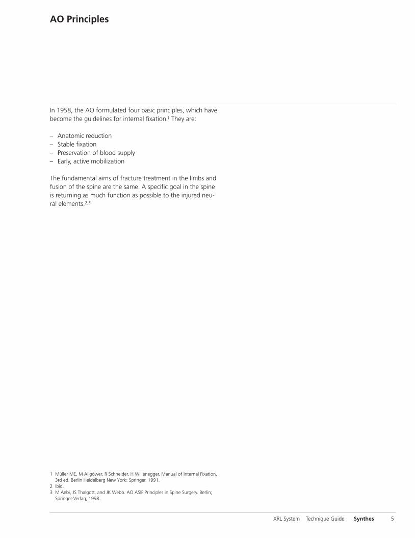
AO Principles
In 1958, the AO formulated four basic principles, which havebecome the guidelines for internal fixation.1 They are:
– Anatomic reduction– Stable fixation– Preservation of blood supply– Early, active mobilization
The fundamental aims of fracture treatment in the limbs andfusion of the spine are the same. A specific goal in the spineis returning as much function as possible to the injured neu-ral elements.2,3
XRL System Technique Guide Synthes 5
1 Müller ME, M Allgöwer, R Schneider, H Willenegger. Manual of Internal Fixation.3rd ed. Berlin Heidelberg New York: Springer. 1991.
2 Ibid.3 M Aebi, JS Thalgott, and JK Webb. AO ASIF Principles in Spine Surgery. Berlin;
Springer-Verlag, 1998.

Indications and Contraindications
IndicationsThe Synthes XRL device is a vertebral body replacement de-vice intended for use in the thoracolumbar spine (T1–L5) toreplace a collapsed, damaged or unstable vertebral body dueto tumor or trauma (i.e., fracture). The Synthes XRL device isintended to be used with Synthes supplemental internal fixa-tion systems (e.g., USS, including MATRIX, Pangea, andTSLP). The interior of Synthes XRL can be packed with bone(i.e., autograft or allograft).
The Synthes XRL device is designed to provide anterior spinalcolumn support even in the absence of fusion for a pro-longed period.
Contraindications1. Use of the Synthes XRL device is contraindicated when
there is active systemic infection, infection localized to thesite of the proposed implantation, or when the patienthas demonstrated allergy or foreign body sensitivity to anyof the implant materials.
2. Severe osteoporosis may prevent adequate fixation andthus preclude the use of this or any other orthopaedic implant.
3. Conditions that may place excessive stresses on bone andimplants, such as severe obesity or degenerative diseases,are relative contraindications. The decision whether to usethese devices in patients with such conditions must bemade by the physician, taking into account the risks versus the benefits to the patient.
4. Use of these implants is relatively contraindicated in patients whose activity, mental capacity, mental illness, alcoholism, drug abuse, occupation or lifestyle may inter-fere with their ability to follow postoperative restrictions,thereby placing undue stresses on the implant duringbony healing. This could result in a higher risk of implantfailure.
Please refer to package insert for the full list ofindications, contraindications, warnings and/orprecautions.
6 Synthes XRL System Technique Guide

Preparation
1Access
Various approaches are suitable depending on the affectedspinal level involved.
The following surgical technique is described using a lateralapproach from the left at L1.
2Perform corpectomy
Perform a partial or complete corpectomy as required.
Note: Remove the superficial layers of the entire cartilagi-nous endplates and expose bleeding bone. Excessive removalof subchondral bone may weaken the vertebral endplate. Ifthe entire endplate is removed, subsidence and a loss of seg-mental stability may occur.
XRL System Technique Guide Synthes 7

Insert Trial Implant
The XRL Vertebral Body Replacement contains a completeline of central body and endplate trial implants that corre-spond to each central body and endplate implant. Trials areplaced into the corpectomy site intraoperatively to determinethe appropriate endplate footprint, angle, and central bodyheight.
1Determine defect
Instruments
03.661.010 Metal Tape Gauge
324.092* Measuring Forceps
The metal tape gauge or measuring forceps can be used tomeasure overall defect.
Note: If final distracted corpectomy height is less than 32 mm, then skip to Step 4 and use the integrated trials.
8 Synthes XRL System Technique Guide
*Also available

XRL System Technique Guide Synthes 9
2Select endplate footprint size and angle
Instruments
XRL Medium Endplate Footprint Trials 03.807.364 21 mm round03.807.365 21 mm x 24 mm03.807.366 26 mm x 30 mm
XRL Large Endplate Footprint Trials03.807.367 27 mm round03.807.368 28 mm x 33 mm03.807.369 30 mm x 40 mm
The endplate footprint trial can be adjusted to accommodatethe desired approach. Pull the sleeve (1) and turn the end-plate trial to the desired position (2). Release the sleeve tolock the position of the trial.
Determine the footprint using the endplate footprint trial.The handles of the endplate footprint trials are color-codedgreen and blue to match the medium and large sets, respec-tively. Determine the angle using lateral x-ray imaging.
12

Insert Trial Implant
3Determine central body sizeThe optimal central body height is calculated using endplatetrial height which is found on the back of the module lid forreference. The trials do not account for the implant spikes;therefore, 2 mm clearance on each end of the trial is required.
Optimal Central Body Height (CBH) = Overall defect –Cranial trial endplate height − Caudal trial endplate height –Clearance for spikes
Example for 70 mm defect with a 5° cranial endplate and 0°caudal endplate:
CBH = 70 mm − 6.5 mm − 5 mm − 4 mmCBH = 55 mm
Insert the selected trial endplates onto the trial central body.Align the etch lines before pressing the components to-gether. Ensure there is no gap between the endplate andcentral body trial.
Note: The endplate height is independent of the footprint.
Warning: The trials are not for implantation and must be re-moved before insertion of the XRL implant. Total constructangle must not exceed 30° lordosis/kyphosis.
10 Synthes XRL System Technique Guide
Medium Endplate Trial Large Endplate TrialAngle Height (mm) Angle Height (mm)0° 5 0° 5.55° 6.5 5° 7 10° 8.5 10° 9.515° 10.5 15° 12-5° 6.5 20° 14.5-10° 8.5

4Insert trial
Instruments
03.807.382 XRL Medium Implant Holder
03.807.384 XRL Large Implant Holder
Using the implant holder, insert the trial into the corpectomysite. Be sure the appropriate endplate is oriented in the cra-nial/caudal position. The optimal position for the trial is cen-tered on the vertebral bodies with clearance to account forthe implant spikes. Trials must always be securely held whilein the wound.
Note: Integrated implants do not have tall spikes and there-fore the integrated trials are the same height as the corre-sponding collapsed implant.
Change trial central body and endplates as necessary toachieve the optimal height, angle, and footprint.
XRL System Technique Guide Synthes 11
2 mm
Implant Insertion
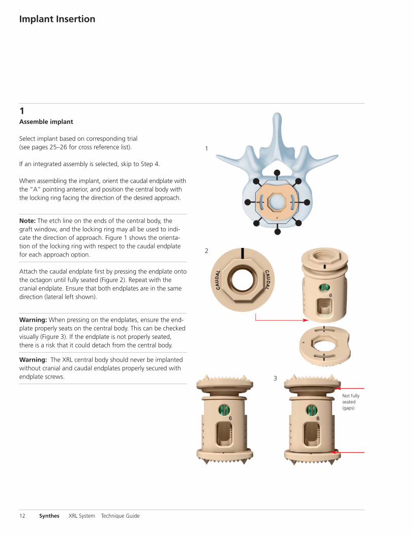
1Assemble implant
Select implant based on corresponding trial (see pages 25–26 for cross reference list).
If an integrated assembly is selected, skip to Step 4.
When assembling the implant, orient the caudal endplate withthe “A” pointing anterior, and position the central body withthe locking ring facing the direction of the desired approach.
Note: The etch line on the ends of the central body, thegraft window, and the locking ring may all be used to indi-cate the direction of approach. Figure 1 shows the orienta-tion of the locking ring with respect to the caudal endplatefor each approach option.
Attach the caudal endplate first by pressing the endplate ontothe octagon until fully seated (Figure 2). Repeat with the cranial endplate. Ensure that both endplates are in the samedirection (lateral left shown).
Warning: When pressing on the endplates, ensure the end-plate properly seats on the central body. This can be checkedvisually (Figure 3). If the endplate is not properly seated,there is a risk that it could detach from the central body.
Warning: The XRL central body should never be implantedwithout cranial and caudal endplates properly secured withendplate screws.
12 Synthes XRL System Technique Guide
Not fullyseated(gaps)
1
2
3

2Reposition endplates (optional)
Instrument
03.807.354 XRL Endplate Removal Tool
If necessary, the endplates can be repositioned by manuallyremoving them from the central body, except for the roundendplates which are removed using the XRL endplate removaltool. Be sure to perform endplate removal over a sterile table.
Warning: Endplates release from central body abruptly.Make sure to have a firm grip on both the central body andthe endplate during removal.
To remove round endplates, align the tip of the XRL endplateremoval tool with the slot in the endplate. Apply a slight,constant pressure and rotate the tool to release the endplate.
XRL System Technique Guide Synthes 13

Implant Insertion
3Attach endplate screws
Instruments
03.807.351 XRL Medium Endplate Screwdriver Tip
03.807.352 XRL Large Endplate Screwdriver Tip
03.807.357 XRL Medium Torque Limiting Handle
03.807.358 XRL Large Torque Limiting Handle
Align the endplate screwdriver tip into the open end of thetorque limiting handle.
Press until an audible “click” is heard.
Align the tri-lobal feature of the tip and the etchings on theendplate screw. Lightly press the screw onto the screwdrivertip. The screwdriver tip will retain the screw.
Align the screw with the caudal endplate to prevent crossthreading. While gripping the large end of the torque limit-ing handle, rotate the torque limiting handle clockwise to ad-vance the screw through the caudal endplate and into thecentral body. Tighten until an audible “click” in the torquehandle is heard. Repeat this step to fixate the cranial end-plate.
Warning: The torque limiting handles are color-coded greenand blue to match the medium and large sets, respectivelyand may only be used with its corresponding set.
Note: Please follow torque limiting handle calibration in-structions to ensure proper functionality.
14 Synthes XRL System Technique Guide

4Prepare implant
Instruments
03.807.371 XRL Medium Graft Packing Tamp
03.807.372 XRL Large Graft Packing Tamp
03.807.374 XRL Medium Graft Packing PreparationTamp
03.807.375 XRL Large Graft Packing Preparation Tamp
Prior to implanting, use graft packing tamps to facilitatepacking of bone graft into the XRL implant. Graft can bepacked through the cannulation in the endplate and graftwindows.
Warning: Do NOT pack graft into the locking ring. DO NOTuse excessive force while packing graft.
Note: Graft packing tamp will not fit inside the window ofintegrated implant #1.
XRL System Technique Guide Synthes 15

Implant Insertion
5Assemble spreader instrument
Instruments
03.807.300 XRL Spreader
03.807.310 XRL Medium Shaft
03.807.311– XRL Medium Spreader Tops,03.807.315 with 3, 5, 8, 10, or 15 mm distraction
03.807.330 XRL Large Shaft
03.807.331– XRL Large Spreader Tops,03.807.335 with 3, 5, 8, 10, or 15 mm distraction
03.807.348 XRL Release Tool
03.807.355 XRL Medium Spreader Top, with 5 mmdistraction (Integrated)
03.807.356 XRL Large Spreader Top, with 5 mmdistraction (Integrated)
Assemble the appropriate size spreader top to the XRLspreader according to the implant central body size selected.The spreader tops are designed to prevent over-distractingthe implant.
Note: The underside of the built-in lid of the graphic caseshows Spreader Top and its corresponding implant selection.
While holding the spreader with the shaft in the horizontalposition, set ratchet lever to the “OFF” position (Figure 1).
Press T-driver release button and pull back on the T-driver (Figure 2). Release the button to set T-driver in the open position (Figure 3). T-driver should not be fully removed during this operation.
Insert the selected spreader top into the spreader shaft (4) and insert the T-driver (5) by gently pushing and turningthe T-driver into the outer shaft assembly.
Check functionality of spreader top by rotating T-driver. Ifproperly assembled, spreader top should translate during T-driver rotation.
16 Synthes XRL System Technique Guide
1 2
3
4
5

6Secure Implant to Spreader
Instruments
03.807.300 XRL Spreader
03.807.310 XRL Medium Shaft
03.807.311– XRL Medium Spreader Tops,03.807.315 with 3, 5, 8, 10, or 15 mm distraction
03.807.330 XRL Large Shaft
03.807.331– XRL Large Spreader Tops,03.807.335 with 3, 5, 8, 10, or 15 mm distraction
03.807.348 XRL Release Tool
03.807.355/ XRL Spreader Top, Integrated03.807.356 (medium or large)
To load the implant, fully collapse the spreader top and setthe ratchet lever to the “ON” position (Figure 1).
With the locking ring facing the instrument, slide thespreader top into the slots below the cranial endplate (Figure 2). Do not force spreader top onto implant. Slightlyturn the T-driver clockwise until the notch on the fork of the spreader shaft engages the implant for a secure hold (Figure 3).
Set the scale to zero (Figure 4).
Completely insert the release tool through the XRL spreaderand into the locking ring. An audible “click” will be heard(Figure 5).
XRL System Technique Guide Synthes 17
1
4
2
3
5

Implant Insertion
7Insert implant
Instrument
03.807.300 XRL Spreader
The spreader handle can be rotated at 90° increments to aidin visualization. Set ratchet lever to “OFF” position (1). Withone hand gripping the spreader shaft, pull back on retainingcollar and rotate the spreader handle to the desired position(2,3). Release retaining collar. Verify that the spreader handleis locked into position. Reset scale to zero.
Warning: Do not adjust spreader handle when ratchet leveris set to “ON.” This will result in premature distraction of theimplant. Do not begin distraction until spreader handle islocked into desired position.
Guide and position the implant with the spreader. Slight distraction of the vertebral bodies may be necessary to easeinsertion.
The optimal position for the implant is in the center of thevertebral body endplate. Maintain space around the endplateof the implant to allow peripheral bony fusion.
Warning: Do not impact on spreader. Do not manipulateimplant unless both the slot and notch are engaged.
Verify the position of the implant using the image intensifier. – A titanium locking ring is used to determine orientation of
the implant – The 1 mm diameter tantalum markers are embedded into
the PEEK endplates to provide radiographic markers for intraoperative or postoperative imaging
– The anterior and medial/lateral markers are located approximately 1 mm from the edges of the implant. Theposterior marker is located 1 mm from the edge of theround implant, and 2 mm from the edge of the anatomi-cally shaped endplates. The cranial/caudal locations of themarkers are 2 mm from the end of the pyramidal teeth.
18 Synthes XRL System Technique Guide
1
2
3

8Distract and check position
Instrument
03.807.300 XRL Spreader
The spreader allows for expansion in both a ratchet modeand continuous mode.
Option A: Ratchet ModeFor ratchet mode, ensure the ratchet lever is set to the ”ON”position and the release tool is engaged, then turn thespreader T-driver clockwise (Figure 1) and expand the implant until the desired amount of distraction is achieved.
Option B: Continuous ModeFor continuous mode, ensure the ratchet lever is set to the”OFF” position and the release tool is engaged, then turnthe spreader T-driver clockwise and expand the implant until the desired amount of distraction is achieved. With constant clockwise torque on the T-driver, set the ratchetlever to the ”ON” position.
Once the implant has been distracted, disengage the releasetool, set the release tool to the resting position (Figure 2) andwith constant clockwise torque on the T-driver, place theratchet lever in the ”OFF” position.
Close the spreader by turning the T-driver counterclockwise.Remove the spreader from the implant.
Visually inspect implant/vertebral body interface for gaps to prevent point loading. If a gap is found, repositioning is necessary to ensure full endplate surface contact.
Verify the position of the implant using the image intensifier.
Do not reuse XRL implants once they have been implanted orexplanted.
Warning: Do not reposition spreader handle during or afterdistraction.
Distraction of the implant is only permitted with the XRL instrument set.
XRL System Technique Guide Synthes 19
1
2

Implant Insertion
9Reposition implant (optional)
Instrument
03.807.300 XRL Spreader
To reposition the implant, fully collapse the spreader top andset the ratchet lever to the “ON” position (Figure 1).
Be sure the release tool is disengaged and set to the restingposition (Figure 2).
Slide the spreader top into the slots below the cranial end-plate. Turn the T-driver clockwise until the notch on the bottom fork engages the implant for a secure hold (Figure 3).Re-engage the release tool until an audible “click” is heard(Figure 4).
Set the ratchet lever to “OFF” position and compress the implant by turning the T-driver counterclockwise. Repositionthe implant to the desired location and follow previous stepto re-distract implant.
Warning: Do not impact on the XRL endplates when reposi-tioning the implant.
Repositioning of the implant is only permitted with the XRLInstrument Set.
20 Synthes XRL System Technique Guide
1
4
2 3

10Verify lock
When the implant is in its final position, verify the lockingring on the central body is closed. When the slot is approxi-mately 1 mm (Figure 1), the implant is locked and secured. Ifthe slot is larger (Figure 2), re-engage the implant with thespreader, and with the release tool in the resting position,distract the implant slightly to close the locking ring.
Warning: Locking ring must be properly closed to ensure final implant height is maintained.
XRL System Technique Guide Synthes 21
1 2
Supplemental Fixation
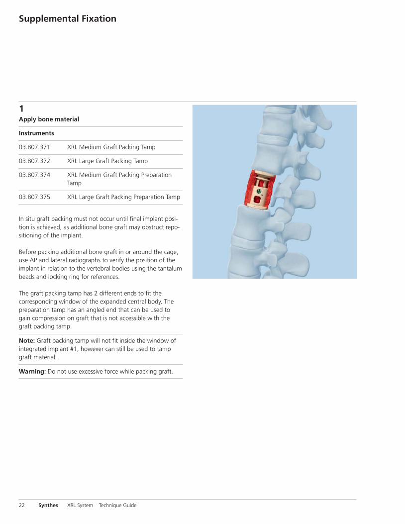
1Apply bone material
Instruments
03.807.371 XRL Medium Graft Packing Tamp
03.807.372 XRL Large Graft Packing Tamp
03.807.374 XRL Medium Graft Packing PreparationTamp
03.807.375 XRL Large Graft Packing Preparation Tamp
In situ graft packing must not occur until final implant posi-tion is achieved, as additional bone graft may obstruct repo-sitioning of the implant.
Before packing additional bone graft in or around the cage,use AP and lateral radiographs to verify the position of theimplant in relation to the vertebral bodies using the tantalumbeads and locking ring for references.
The graft packing tamp has 2 different ends to fit the corresponding window of the expanded central body. Thepreparation tamp has an angled end that can be used togain compression on graft that is not accessible with thegraft packing tamp.
Note: Graft packing tamp will not fit inside the window ofintegrated implant #1, however can still be used to tampgraft material.
Warning: Do not use excessive force while packing graft.
22 Synthes XRL System Technique Guide

2Apply supplemental fixation
For spinal stability and to maintain adequate compression on the construct, the XRL system is indicated for use withsupplemental fixation.
XRL System Technique Guide Synthes 23

Implants
Modular XRL ImplantsXRL Medium– 21 mm central body diameter– Endplate footprint options:
– 21 mm round– 21 mm x 24 mm – 26 mm x 30 mm
– Construct heights range from 32 mm (fully compressed) to 142 mm (fully expanded)
– Various lordotic/kyphotic angulation options
XRL Large– 27 mm body diameter– Endplate footprint options:
– 27 mm round– 28 mm x 33 mm – 30 mm x 40 mm
– Construct heights range from 34 mm (fully compressed)to 145 mm (fully expanded)
– Various lordotic angulation options
Integrated XRL ImplantsXRL Medium– 21 mm central body diameter– 21 mm endplate footprint– Heights range from 22 mm (fully compressed) to
36 mm (fully expanded)– 0° parallel endplates
XRL Large– 27 mm body diameter– 28 mm endplate footprint– Heights range from 23 mm (fully compressed) to 37 mm
(fully expanded)– 0° parallel endplates
24 Synthes XRL System Technique Guide
Note: All XRL implants are supplied sterile

XRL System Technique Guide Synthes 25
XRL Trial Implants
Instruments
The XRL vertebral body replacement contains a complete lineof central body and endplate trials that correspond to eachcentral body and endplate implant. Trials are placed into thecorpectomy site intraoperatively to determine the appropri-ate implant footprint, lordotic angle and central body height.
Use the central body and endplate trials to determine the
largest implant size (integrated or modular) that will fit themeasured corpectomy site. Trials may be secured and low-ered into corpectomy defect using the implant holder. Allow2 mm clearance on each end for the tall spikes on the end-plates (modular only).
Part Number Description Part Number
Trial Implants Central Bodies Size Corresponding (mm) Implants
03.807.501 Integrated 1 08.807.201S22–25 height, 0°
03.807.502 Integrated24–29 height, 0° 2 08.807.202S
03.807.503 Integrated28–36 height, 0° 3 08.807.203S
03.807.504 22–27 height 4 08.807.204S
03.807.505 25–33 height 5 08.807.205S
03.807.506 29–39 height 6 08.807.206S
03.807.507 33–43 height 7 08.807.207S
03.807.508 37–52 height 8 08.807.208S
03.807.509 44–59 height 9 08.807.209S
03.807.510 51–66 height 10 08.807.210S
03.807.511 62–77 height 11 08.807.211S
03.807.512 73–88 height 12 08.807.212S
03.807.513 84–99 height 13 08.807.213S
03.807.514 95–110 height 14 08.807.214S
03.807.515 106–121 height 15 08.807.215S
Part Number Description Part Number
Trial Implants Central Bodies Size Corresponding (mm) Implants
03.807.601 Integrated 1 08.807.301S23–26 height, 0°
03.807.602 Integrated25–30 height, 0° 2 08.807.302S
03.807.503 Integrated29–37 height, 0° 3 08.807.303S
03.807.604 22–27 height 4 08.807.304S
03.807.605 25–33 height 5 08.807.305S
03.807.606 29–39 height 6 08.807.306S
03.807.607 33–43 height 7 08.807.307S
03.807.608 37–52 height 8 08.807.308S
03.807.609 44–59 height 9 08.807.309S
03.807.610 51–66 height 10 08.807.310S
03.807.611 62–77 height 11 08.807.311S
03.807.612 73–88 height 12 08.807.312S
03.807.613 84–99 height 13 08.807.313S
03.807.614 95–110 height 14 08.807.314S
03.807.615 106–121 height 15 08.807.315S
Medium Trials (green) Large Trials (blue)
Integrated Standard Integrated Standard

26 Synthes XRL System Technique Guide
InstrumentsXRL Trial Implants
Part Number Description Corresponding (mm) Implants
03.807.521 21 Round, 0° 08.807.221S
03.807.522 21 Round, 5° 08.807.222S
03.807.523 21 Round, 10° 08.807.223S
03.807.524 21 Round, 15° 08.807.224S
03.807.531 21 x 24, -10° 08.807.231S
03.807.532 21 x 24, -5° 08.807.232S
03.807.533 21 x 24, 0° 08.807.233S
03.807.534 21 x 24, 5° 08.807.234S
03.807.535 21 x 24, 10° 08.807.235S
03.807.536 21 x 24, 15° 08.807.236S
03.807.541 26 x 30, -10° 08.807.241S
03.807.542 26 x 30, -5° 08.807.242S
03.807.543 26 x 30, 0° 08.807.243S
03.807.544 26 x 30, 5° 08.807.244S
03.807.545 26 x 30, 10° 08.807.245S
03.807.546 26 x 30, 15° 08.807.246S
Part Number Description Corresponding (mm) Implants
03.807.621 27 round, 0° 08.807.321S
03.807.622 27 round, 5° 08.807.322S
03.807.623 27 round, 10° 08.807.323S
03.807.624 27 round, 15° 08.807.324S
03.807.625 27 round, 20° 08.807.325S
03.807.631 28 x 33, 0° 08.807.331S
03.807.632 28 x 33, 5° 08.807.332S
03.807.633 28 x 33, 10° 08.807.333S
03.807.634 28 x 33, 15° 08.807.334S
03.807.635 28 x 33, 20° 08.807.335S
03.807.641 30 x 40, 0° 08.807.341S
03.807.642 30 x 40, 5° 08.807.342S
03.807.643 30 x 40, 10° 08.807.343S
03.807.644 30 x 40, 15° 08.807.344S
03.807.645 30 x 40, 20° 08.807.345S
Medium Trial Endplates (green) Large Trial Endplates (blue)

03.807.300 XRL Spreader For implanting, distracting, and
compressing (repositioning the implant)
Ratchet LeverA ratchet lever on the instrument handle allows for the manipulations of the XRL implant.
Note: Release tool must be engaged with locking ring forimplant manipulation.
T-driver ReleaseAllows the T-driver to be disengaged/removed from thespreader
Shaft ReleaseAllows the spreader shaft to be removed from the from thespreader
Retaining CollarAllows 90° rotation of the spreader handle
ScaleUsed to determine the achieved amount of expansion
T-driverAllows expansion or compression of the implantClockwise = expansionCounterclockwise = compression
XRL System Technique Guide Synthes 27
Ratchet Mode “ON”allows expansion ofthe implant
Continuous Mode“OFF” allows tactileexpansion orcompression of theimplant

03.661.010 Metal Tape Gauge
Instruments
03.807.348 Release Tool Enables implant repositioning
Spreader topsMediumAvailable in six distraction ranges, dependent on the centralbody implant.03.807.311 with 3 mm distraction03.807.312 with 5 mm distraction03.807.313 with 8 mm distraction03.807.314 with 10 mm distraction03.807.315 with 15 mm distraction03.807.355 with 5 mm distraction (integrated)
Large03.807.331 with 3 mm distraction03.807.332 with 5 mm distraction03.807.333 with 8 mm distraction03.807.334 with 10 mm distraction03.807.335 with 15 mm distraction03.807.356 with 5 mm distraction (integrated)
28 Synthes XRL System Technique Guide
03.807.310 XRL Medium Shaft03.807.330 XRL Large Shaft (shown)
XRL Endplate Screwdriver Tips03.807.351 Medium03.807.352 Large

Endplate Footprint Trials03.807.364 Medium 21 mm round03.807.365 Medium 21 mm X 24 mm03.807.366 Medium 26 mm X 30 mm03.807.367 Large 27 mm Round03.807.368 Large 28 mm X 33 mm03.807.369 Large 30 mm X 40 mm
Graft Packing Tamps03.807.371 Medium Tamp03.807.374 Medium Preparation Tamp03.807.372 Large Tamp03.807.375 Large Preparation Tamp
Implant Holder03.807.382 Medium Implant Holder (shown)03.807.384 Large Implant Holder For inserting the implant trials
XRL System Technique Guide Synthes 29
XRL Torque Limiting Handles03.807.357 Medium03.807.358 Large
03.807.354 XRL Endplate Removal Tool Allows removal of round endplates from
the central body

Spreader Disassembly
30 Synthes XRL System Technique Guide
1
32
4
5
6
XRL System Technique Guide Synthes 31
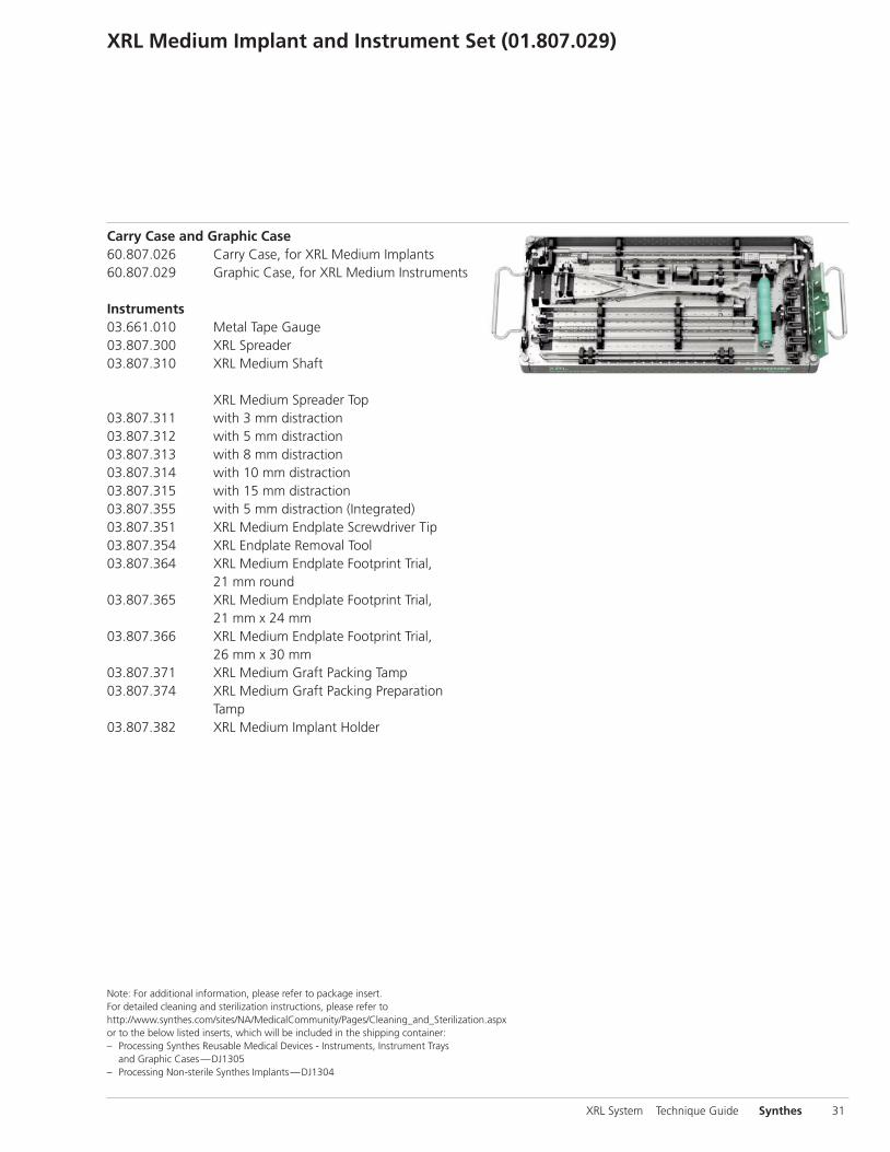
XRL Medium Implant and Instrument Set (01.807.029)
Carry Case and Graphic Case60.807.026 Carry Case, for XRL Medium Implants 60.807.029 Graphic Case, for XRL Medium Instruments
Instruments03.661.010 Metal Tape Gauge03.807.300 XRL Spreader03.807.310 XRL Medium Shaft
XRL Medium Spreader Top03.807.311 with 3 mm distraction03.807.312 with 5 mm distraction03.807.313 with 8 mm distraction03.807.314 with 10 mm distraction03.807.315 with 15 mm distraction03.807.355 with 5 mm distraction (Integrated)03.807.351 XRL Medium Endplate Screwdriver Tip03.807.354 XRL Endplate Removal Tool03.807.364 XRL Medium Endplate Footprint Trial,
21 mm round03.807.365 XRL Medium Endplate Footprint Trial,
21 mm x 24 mm03.807.366 XRL Medium Endplate Footprint Trial,
26 mm x 30 mm03.807.371 XRL Medium Graft Packing Tamp03.807.374 XRL Medium Graft Packing Preparation
Tamp03.807.382 XRL Medium Implant Holder
Note: For additional information, please refer to package insert. For detailed cleaning and sterilization instructions, please refer to http://www.synthes.com/sites/NA/MedicalCommunity/Pages/Cleaning_and_Sterilization.aspxor to the below listed inserts, which will be included in the shipping container: – Processing Synthes Reusable Medical Devices - Instruments, Instrument Trays
and Graphic Cases—DJ1305 – Processing Non-sterile Synthes Implants—DJ1304

XRL Medium Implant and Instrument Set (01.807.029)
ImplantsXRL Medium Implant, Integrated, 0°, sterile Height08.807.201S 22 mm–25 mm08.807.202S 24 mm–29 mm08.807.203S 28 mm–36 mm
XRL Medium Central Body, sterile Height08.807.204S 22 mm–27 mm08.807.205S 25 mm–33 mm08.807.206S 29 mm–39 mm08.807.207S 33 mm–43 mm08.807.208S 37 mm–52 mm08.807.209S 44 mm–59 mm08.807.210S 51 mm–66 mm08.807.211S 62 mm–77 mm
XRL Medium Endplate, 21 mm round, sterile08.807.221S 0°08.807.222S 5°08.807.223S 10°08.807.224S 15°
XRL Medium Endplate, 21 mm x 24 mm, sterile08.807.231S -10°08.807.232S -5°08.807.233S 0°08.807.234S 5°08.807.235S 10°08.807.236S 15°
XRL Medium Endplates, 26 mm x 30 mm, sterile08.807.241S -10°08.807.242S -5°08.807.243S 0°08.807.244S 5°08.807.245S 10°08.807.246S 15°
08.807.200.02S XRL Medium Endplate Screws
Also Available8205 XRL Preoperative Planner, medium08.807.212S XRL Medium Central Body, 73 mm–88 mm
height, sterile08.807.213S XRL Medium Central Body, 84 mm–99 mm
height, sterile08.807.214S XRL Medium Central Body,
95 mm–110 mm height, sterile08.807.215S XRL Medium Central Body,
106 mm–121 mm height, sterile
32 Synthes XRL System Technique Guide

XRL System Technique Guide Synthes 33
XRL Medium Trial Instrument Set (01.807.032)
Graphic Case60.807.032 Graphic Case, for XRL Medium Trials
TrialsXRL Medium Trial, Integrated, 0° Height03.807.501 22 mm–25 mm03.807.502 24 mm–29 mm03.807.503 28 mm–36 mm
XRL Medium Trial, Central Body Height03.807.504 22 mm–27 mm03.807.505 25 mm–33 mm03.807.506 29 mm–39 mm03.807.507 33 mm–43 mm03.807.508 37 mm–52 mm03.807.509 44 mm–59 mm03.807.510 51 mm–66 mm03.807.511 62 mm–77 mm
XRL Medium Trial, Endplate, 21 mm round03.807.521 0°03.807.522 5°03.807.523 10°03.807.524 15°
XRL Medium Trial Endplate, 21 mm x 24 mm03.807.531 -10°03.807.532 -5°03.807.533 0°03.807.534 5°03.807.535 10°03.807.536 15°
XRL Medium Trial Endplate, 26 mm x 30 mm03.807.541 -10°03.807.542 -5°03.807.543 0°03.807.544 5°03.807.545 10°03.807.546 15°
Also Available03.807.512 XRL Medium Trial, Central Body,
73 mm–88 mm height03.807.513 XRL Medium Trial, Central Body,
84 mm–99 mm height03.807.514 XRL Medium Trial, Central Body,
95 mm–110 mm height03.807.515 XRL Medium Trial, Central Body,
106 mm–121 mm height

34 Synthes XRL System Technique Guide
XRL Large Implant and Instrument Set (01.807.030)
Cary Case and Graphic Case60.807.027 Carry Case, for XRL Large Implants60.807.030 Graphic Case, for XRL Large Instrument
Instruments03.661.010 Metal Tape Gauge03.807.300 XRL Spreader03.807.330 XRL Large Shaft
XRL Large Spreader Top03.807.331 with 3 mm distraction03.807.332 with 5 mm distraction03.807.333 with 8 mm distraction03.807.334 with 10 mm distraction03.807.335 with 15 mm distraction03.807.356 with 5 mm distraction (Integrated)03.807.348 XRL Release Tool03.807.352 XRL Large Endplate Screwdriver Tip03.807.354 XRL Endplate Removal Tool03.807.367 XRL Large Endplate Footprint Trial,
27 mm round03.807.368 XRL Large Endplate Footprint Trial,
28 mm x 33 mm03.807.369 XRL Large Endplate Footprint Trial,
30 mm x 40 mm03.807.372 XRL Large Graft Packing Tamp03.807.375 XRL Large Graft Packing Preparation Tamp03.807.384 XRL Large Implant Holder08.807.300.02S XRL Large Endplate Screw (PEEK), sterile

XRL System Technique Guide Synthes 35
ImplantsXRL Large Implant, Integrated, 0°, sterile Height08.807.301S 23 mm–26 mm08.807.302S 25 mm–30 mm08.807.303S 29 mm–37 mm
XRL Large Central Body, sterile Height08.807.304S 22 mm–27 mm08.807.305S 25 mm–33 mm08.807.306S 29 mm–39 mm08.807.307S 33 mm–43 mm08.807.308S 37 mm–52 mm08.807.309S 44 mm–59 mm08.807.310S 51 mm–66 mm08.807.311S 62 mm–77 mm
XRL Large Endplates, 27 mm round, sterile08.807.321S 0°08.807.322S 5°08.807.323S 10°08.807.324S 15°08.807.325S 20° XRL Large Endplates, 28 mm x 33 mm, sterile08.807.331S 0°08.807.332S 5°08.807.333S 10°08.807.334S 15°08.807.335S 20°
XRL Large Endplates, 30 mm x 40 mm, sterile08.807.241S 0°08.807.242S 5°08.807.243S 10°08.807.244S 15°08.807.245S 20°
Also Available8206 XRL Preoperative Planner, Large08.807.312S XRL Large Central Body,
73 mm–88 mm height, sterile08.807.313S XRL Large Central Body,
84 mm–99 mm height, sterile08.807.314S XRL Large Central Body,
95 mm–110 mm height, sterile08.807.315S XRL Large Central Body,
106 mm–121 mm height, sterile

XRL Large Trial Instrument Set (01.807.033)
60.807.033 Graphic Case, for XRL Large Trials
TrialsXRL Large Trial, Integrated, 0°
Height
03.807.601 23 mm–26 mm
03.807.602 25 mm–30 mm
03.807.603 29 mm–37 mm
XRL Large Trial, Central Body
Height
03.807.604 22 mm–27 mm
03.807.605 25 mm–33 mm
03.807.606 29 mm–39 mm
03.807.607 33 mm–43 mm
03.807.608 37 mm–52 mm
03.807.609 44 mm–59 mm
03.807.610 51 mm–66 mm
03.807.611 62 mm–77 mm
XRL Large Trial, Endplate, 27 mm round
03.807.621 0°
03.807.622 5°
03.807.623 10°
03.807.624 15°
03.807.625 20°
XRL Large Trial, Endplate, 28 mm x 33 mm
03.807.631 0°
03.807.632 5°
03.807.633 10°
03.807.634 15°
03.807.635 20°
XRL Large Trial, Endplate, 30 mm x 40 mm
03.807.641 0°
03.807.642 5°
03.807.643 10°
03.807.644 15°
03.807.645 20°
36 Synthes XRL System Technique Guide
Also Available03.807.612 XRL Large Trial, Central Body,
73 mm–88 mm height
03.807.613 XRL Large Trial, Central Body, 84 mm–99 mm height
03.807.614 XRL Large Trial, Central Body, |95 mm–110 mm height
03.807.615 XRL Large Trial, Central Body, 106 mm–121 mm height


Synthes USA1302 Wrights Lane EastWest Chester, PA 19380Telephone: (610) 719-5000To order: (800) 523-0322Fax: (610) 251-9056
Synthes (Canada) Ltd.2566 Meadowpine BoulevardMississauga, Ontario L5N 6P9Telephone: (905) 567-0440To order: (800) 668-1119Fax: (905) 567-3185
© 2011 Synthes, Inc. or its affiliates. All rights reserved. MATRIX, Pangea, USS, XRL and Synthes are a trademarks of Synthes, Inc. or its affiliates. Printed in U.S.A. 12/11 J11184-A
www.synthes.com
Recommended