Part number 550-142-058/0811
WM97+ gas-fired water boiler — Boiler Manual
94
Replacement parts
Figure 92 Propane conversion kits and instructions
Boiler model
Kit part #
Kit location
Installation instructions
WM97+70 540-202-834 Shipped loose with boiler See page 12
WM97+110 540-202-835 Shipped loose with boiler See page 12
Failure to adhere to these guidelines can result in severe personal injury, death or substantial property damage.
OBTAIN PARTS ONLY THROUGH WEIL-McLAIN
Replacement parts must be purchased through a local Weil-McLain distributor. When ordering, specify boiler model and size and include description and part number of replacement part. Results from us-ing modified or other manufactured parts will not be covered by warranty and may damage boiler or impair operation.
THE BOILER CONTAINS CERAMIC FIBER MATERIALS
The boiler contains ceramic fiber materials. Use care when handling these materials per instructions on page 76 of this manual. Failure to comply could result in severe personal injury.
REINSTALL JACKET DOOR
Inspect boiler jacket front door gaskets and reinstall boiler jacket front door after start or servicing. The boiler front door must be se-curely fastened to the boiler to prevent boiler from drawing air from inside the boiler room. This is particularly important if the boiler is located in the same room as other appliances. Failure to keep the door securely fastened could result in severe personal injury or death.
BEFORE SERVICING or MAKING CONNECTIONS —
ALWAYS TURN POWER OFF TO THE BOILER TO PREVENT ELECTRICAL SURGES, WHICH CAN DAMAGE BOILER COMPONENTS.
LABEL WIRES BEFORE REMOVING
Label all wires prior to disconnection when servicing controls. Wir-ing errors can cause improper and dangerous operation.
DO NOT SERVICE THE BOILER WITHOUT A WM97+ MAINTENANCE KIT AVAILABLE
The WM97+ maintenance kit includes compo-
nents that may have to be replaced when access-
ing or disassembling parts of the boiler. Failure
to replace damaged components and to use only
the parts specifically intended for the boiler can
result in severe personal injury, death or substan-
tial property damage. See Figure 93, page 95 for
part number.
REPLACEMENT PART NUMBERS
Weil-McLain part numbers are found in
this manual and in Weil-McLain Boilers
and Controls Repair Parts Lists.
WHEN OPERATING THE BOILER ON PROPANE GAS
ALL WM97+ boilers must be converted in order to operate with propane gas.
Go to www.weil-mclain.com to locate Weil-McLain distributors

Part number 550-142-058/0811 95
WM97+ gas-fired water boiler — Boiler Manual
Figure 93 Miscellaneous parts and kits
Replacement parts (continued)
Go to www.weil-mclain.com to locate Weil-McLain distributors
Item Description Part Number
CHEMICALS
100
Antifreeze, Sentinel X500. . . . . . . . . . . .Corrosion inhibitor, Sentinel X100 . . . . . . .Sentinel X100 Quick Test Kit . . . . . . . . . .Cleaner, Sentinel X400 . . . . . . . . . . . . .
592-900-004592-900-002592-900-005592-900-003
BOILER ACCESSORIES
110
WM97+ maintenance kit — igniter, igniter gasket, venturi gasket, cover plate gasket, venturi-gas valve o-ring, refractory, silicone, inhibitor test kit, clips
383-700-165
120 Wall-mount kit (supplied with boiler ) — wall mount bracket and hardware
383-700-118
130 Condensate trap kit (supplied with boiler) — condensate trap assembly and flexible line
560-907-722
CONDENSATE HANDLING ACCESSORIES
140 Condensate neutralizer kit 383-500-631
POLYPROPYLENE VENT/AIR TERMINATIONS PARTS AND KITS available from M&G Simpson-Duravent ONLY
150
M&G Simpson-Duravent PolyPro SIDEWALL concentric vent/air kit (color: white) 2” polypropylene pipe . . . . . . . . . . . . 3” polypropylene pipe . . . . . . . . . . . .
24PPS-HK35PPS-HK
160
M&G Simpson-Duravent PolyPro VERTICAL concentric vent/air kit; color = black (VK suffix) or terra cotta (TC suffix) 2” polypropylene pipe . . . . . . . . . . . . 3” polypropylene pipe . . . . . . . . . . . .
24PPS-VK35PPS-VK
170
M&G Simpson-Duravent PolyPro SIDEWALL separate air and vent pipes 2” polypropylene pipe . . . . . . . . . . . . 3” polypropylene pipe . . . . . . . . . . . .
2PPS-HTP3PPS-HTP
Item Description Part Number
VENT/AIR TERMINATION PARTS AND KITS available from Weil-McLain
180
Weil-McLain sidewall vent/air cap termination kit for PVC vent and air pipes Includes W-M sidewall vent/air termination cap, inside and outside cover plates, and mounting hardware; openings are sized for 3” PVC pipe (requires field-installed 3 x 2 adapter if using 2” vent/air pipes)
383-500-397
190
Weil-McLain sidewall vent/air cap termination kit for AL29-4C vent pipe and PVC air pipe Includes W-M sidewall vent/air termination cap, inside and outside cover plates, and mounting hardware; openings are sized for 3” PVC pipe (requires field-installed 3 x 2 adapter if using 2” vent/air pipes)
382-200-430
200
Sidewall separate pipes vent/air termination kits (includes two cover plates)Kit for 2” PVC vent and air pipes . . . . . . . .Kit for 3” PVC vent and air pipes . . . . . . . .Kit for 3” AL29-4C SS vent pipe and PVC air pipe. . . . . . . . . . . . . . . . . . . . . . .
383-700-171383-500-100
383-700-172
210
PVC concentric vent kit — horizontal or vertical (includes components for concentric assembly)Kit for 2” PVC vent and air pipes . . . . . . . .Kit for 3” PVC vent and air pipes . . . . . . . .
383-700-167383-500-350
220
Bird screensFor 2” PVC vent and air pipes . . . . . . . . .For 3” PVC vent and air pipes . . . . . . . . .
560-907-728383-500-105

Part number 550-142-058/0811
WM97+ gas-fired water boiler — Boiler Manual
96
Replacement parts (continued)
Figure 94 Jacket parts (see Figure 95, page 97 for illustration)
Item Name Description / contents Part NumberModel
70 | 110
100 Front door Front door, seals, logo, and labels 383-700-116
110 Front door to jacket seals Seals for front door to jacket 383-700-117
120 Wall-mount bracket (wall side) Bracket and hardware 383-700-118
130 Wall-mount bracket (boiler side) Bracket and hardware 383-700-119
140 Gaskets - upper panel to cabinet Gaskets - top panel to cabinet 383-700-120
150 Gasket - heat exchanger to bottom panel Gasket - condensate trap to bottom panel 383-700-121
160 Door latch Latch and hardware 383-700-122
170 Gasket internal flue pipe to adapter Gasket fits inner diameter of boiler flue pipe 590-318-051
180 Flue pipe adapter Top flue adapter with internal gasket 560-907-719
190 Boiler flue pipe Internal flue pipe and gasket 560-907-720
200 Air inlet adapter Top air inlet adapter with internal gasket 560-907-718
210 Gasket - pipe adapter to cabinet Gasket - flue adapter to cabinet 590-300-031
220 Gasket - pipe adapter to system pipe Gasket fits inner diameter of top adapter 590-318-052
230 Front door to display seal One seal (attached to control housing) 590-300-025
Go to www.weil-mclain.com to locate Weil-McLain distributors

Part number 550-142-058/0811 97
WM97+ gas-fired water boiler — Boiler Manual
Replacement parts (continued)
Figure 95 Jacket assembly (see Figure 94, page 96 for part numbers)
Go to www.weil-mclain.com to locate Weil-McLain distributors
Part number 550-142-058/0811
WM97+ gas-fired water boiler — Boiler Manual
98
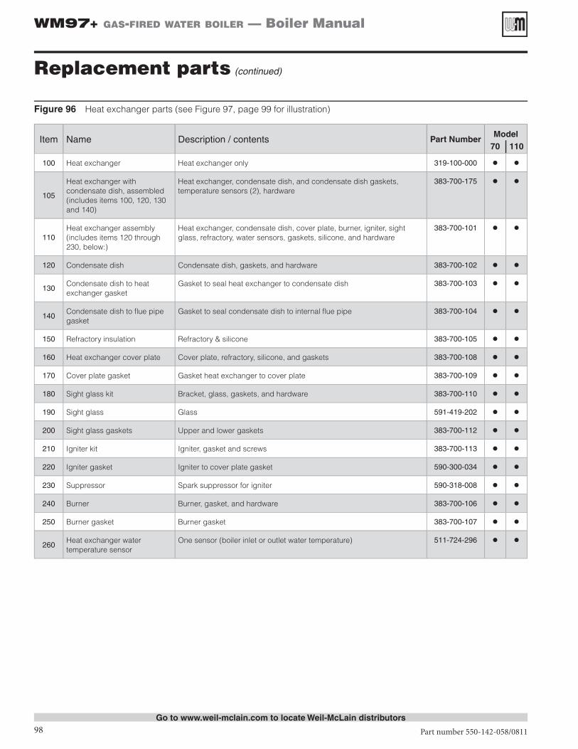
Figure 96 Heat exchanger parts (see Figure 97, page 99 for illustration)
Item Name Description / contents Part NumberModel
70 | 110
100 Heat exchanger Heat exchanger only 319-100-000
105
Heat exchanger with condensate dish, assembled (includes items 100, 120, 130 and 140)
Heat exchanger, condensate dish, and condensate dish gaskets, temperature sensors (2), hardware
383-700-175
110Heat exchanger assembly (includes items 120 through 230, below:)
Heat exchanger, condensate dish, cover plate, burner, igniter, sight glass, refractory, water sensors, gaskets, silicone, and hardware
383-700-101
120 Condensate dish Condensate dish, gaskets, and hardware 383-700-102
130Condensate dish to heat exchanger gasket
Gasket to seal heat exchanger to condensate dish 383-700-103
140Condensate dish to flue pipe gasket
Gasket to seal condensate dish to internal flue pipe 383-700-104
150 Refractory insulation Refractory & silicone 383-700-105
160 Heat exchanger cover plate Cover plate, refractory, silicone, and gaskets 383-700-108
170 Cover plate gasket Gasket heat exchanger to cover plate 383-700-109
180 Sight glass kit Bracket, glass, gaskets, and hardware 383-700-110
190 Sight glass Glass 591-419-202
200 Sight glass gaskets Upper and lower gaskets 383-700-112
210 Igniter kit Igniter, gasket and screws 383-700-113
220 Igniter gasket Igniter to cover plate gasket 590-300-034
230 Suppressor Spark suppressor for igniter 590-318-008
240 Burner Burner, gasket, and hardware 383-700-106
250 Burner gasket Burner gasket 383-700-107
260Heat exchanger water temperature sensor
One sensor (boiler inlet or outlet water temperature) 511-724-296
Replacement parts (continued)
Go to www.weil-mclain.com to locate Weil-McLain distributors

Part number 550-142-058/0811 99
WM97+ gas-fired water boiler — Boiler Manual
Go to www.weil-mclain.com to locate Weil-McLain distributors
Replacement parts (continued)
Figure 97 Heat exchanger assembly (see Figure 96, page 98 for part numbers)
Part number 550-142-058/0811
WM97+ gas-fired water boiler — Boiler Manual
100
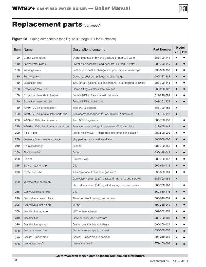
Figure 98 Piping components (see Figure 99, page 101 for illustration)
Item Name Description / contents Part NumberModel
70 | 110
100 Upper water pipes Upper pipe assembly and gaskets (1 pump, 2 water) 383-700-144
110 Lower water pipes Lower pipe assembly and gaskets (1 pump, 2 water) 383-700-145
120 Water gaskets Seal pipe to heat exchanger or upper pipe to lower pipe 590-300-036
130 Pump gasket Gasket to seal pump flange to pipe flange 590-317-543
140 Expansion tank 12 Liter (3.2 gallons) expansion tank - pre-charged to 12 psi 383-700-148
150 Expansion tank line Flared fitting stainless steel flex line 560-900-022
160 Expansion tank shutoff valve Female NPT to flare manual ball valve 511-246-399
170 Expansion tank adapter Female NPT to male flare 562-302-577
180 WM97+70 boiler circulator Taco 007 & gaskets 383-700-152
190 WM97+70 boiler circulator cartridge Replacement cartridge for wet-rotor 007 circulator 511-405-142
200 WM97+110 boiler circulator Taco 0015 & gaskets 383-700-153
210 WM97+110 boiler circulator cartridge Replacement cartridge for wet-rotor 0015 circulator 511-405-143
220 Relief valve 30 Psi relief valve — shipped loose for field installation 383-500-095
230 Pressure & temperature gauge Shipped loose for field installation 380-000-000
240 Air inlet silencer Silencer 383-700-155
250 Silencer o-ring O-ring 590-318-049
260 Blower Blower & clip 383-700-157
265 Blower retainer clip Clip 562-650-115
270 Reference tube Tube to connect blower to gas valve 590-300-001
280 Valve/venturi assemblyGas valve, venturi (027), gasket, o-ring, clip, and screws 383-700-159
Gas valve, venturi (040), gasket, o-ring, clip, and screws 383-700-160
285 Gas valve retainer clip Clip 562-650-116
290 Gas valve adapter block Threaded block, o-ring, and screws 563-910-031
295 Gas valve outlet o-ring O-ring 590-318-045
300 Gas flex line adapter NPT to flare adapter 562-302-576
310 Gas flex line Gas line, seal, and hardware 383-700-163
320 Gas flex line gasket Gasket gas flex line to cabinet 590-300-027
330 Gasket - lower pipe Gasket - lower pipe to cabinet 590-300-037
340 Gasket - upper pipe Gasket - upper pipe to cabinet 590-318-050
350 Low water cutoff Low water cutoff 571-100-006
Replacement parts (continued)
Go to www.weil-mclain.com to locate Weil-McLain distributors

Part number 550-142-058/0811 101
WM97+ gas-fired water boiler — Boiler Manual
Go to www.weil-mclain.com to locate Weil-McLain distributors
Replacement parts (continued)
Figure 99 Piping assemblies (see Figure 98, page 100 for part numbers)
Part number 550-142-058/0811
WM97+ gas-fired water boiler — Boiler Manual
102
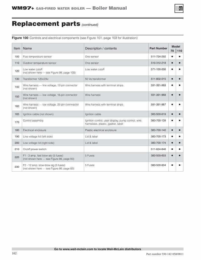
Figure 100 Controls and electrical components (see Figure 101, page 103 for illustration)
Item Name Description / contents Part NumberModel
70 | 110
100 Flue temperature sensor One sensor 511-724-292
110 Outdoor temperature sensor One sensor 510-312-218
120Low water cutoff(not shown here — see Figure 98, page 100)
Low water cutoff 571-100-006
130 Transformer 120v/24v 50 Va transformer 511-802-015
140Wire harness — line voltage, 12-pin connector (not shown)
Wire harness with terminal strips 591-391-969
150Wire harness — low voltage, 16-pin connector(not shown)
Wire harness 591-391-968
160Wire harness — low voltage, 22-pin connnector(not shown)
Wire harness with terminal strips 591-391-967
165 Ignition cable (not shown) Ignition cable 383-500-619
170Control assembly Ignition control, user display, pump control, wire
harnesses, plastic, gasket, label383-700-139
180 Electrical enclosure Plastic electrical enclosure 383-700-140
190 Line voltage lid (left side) Lid & label 383-700-173
200 Low voltage lid (right side) Lid & label 383-700-174
210 On/off power switch 511-624-646
220F1 - 3 amp, fast blow ato (5 fuses)(not shown here — see Figure 86, page 83)
5 Fuses 383-500-603
230F2 - 12 amp, slow-blow ag (5 fuses)(not shown here — see Figure 86, page 83)
5 Fuses 383-500-604
Replacement parts (continued)
Go to www.weil-mclain.com to locate Weil-McLain distributors

Part number 550-142-058/0811 103
WM97+ gas-fired water boiler — Boiler Manual
Go to www.weil-mclain.com to locate Weil-McLain distributors
Replacement parts (continued)
Figure 101 Controls and electrical assemblies (see Figure 100, page 102 for part numbers)

Part number 550-142-058/0811
WM97+ gas-fired water boiler — Boiler Manual
104
Figure 102 Dimensional data (all dimensions in inches)
Dimensions
LEGEND
1 Boiler supply tapping, 1” NPT.
2 Boiler return tapping, 1” NPT.
3Control panel, with display and naviga-tion buttons
4 Electrical entrance openings
5 Vent connection: 3” PVC
6
Pressure/temperature gauge (shipped loosed)
See Figure 6, page 10 for mounting details and instructions.
7Gas connection (note 1) (manual gas valve shipped loose for field installation)
See page 44 for details and instructions.
8Drain valve (shipped loose)
See Figure 6, page 10 for mounting details and instructions.
9Condensate drain connection (also see item 14, below)
10 Air connection: 3" PVC
11
Relief valve (shipped loose)
See page 33 for mounting details. Relief valve mounts on supply pipe off of supply tee and ¾” street elbow as shown.
12
Boiler drain line / DHW boiler water return line (if DHW tank is connected directly to the boiler)
See Figure 7, page 11 for details and in-structions for usage.
13
DHW boiler water supply line (if DHW tank is connected directly to the boiler)
See Figure 7, page 11 for details and in-structions for usage.
14
Condensate trap and flexible drain line (shipped loose)
See page 43 for details and instructions. The condensate drain hose or pipe must connect to the flexible line supplied with the boiler to ensure the trap assembly can be removed easily.
TOP
FRONT RIGHT
TOP (shows field-installed components)
BOTTOM (shows field-installed components)
Part number 550-142-058/0811 105
WM97+ gas-fired water boiler — Boiler Manual
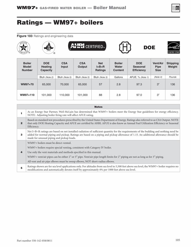
Ratings — WM97+ boilers
Figure 103 Ratings and engineering data
DOE
Boiler Model
Number
DOE Heating Capacity
CSA Input
CSA Output
Net I=B=R
Ratings
Boiler Water
Content
DOE Seasonal Efficiency
Vent/Air PipeSize
Shipping Weight
Btuh (Note 2) Btuh (Note 5) Btuh (Note 5) Btuh (Note 3) Gallons AFUE, % (Note 1) (Note 4) Pounds
WM97+70 65,000 70,000 65,000 57 2.8 97.3 3” 136
WM97+110 101,000 110,000 101,000 88 2.8 97.0 3” 136
Notes
1As an Energy Star Partner, Weil-McLain has determined that WM97+ boilers meet the Energy Star guidelines for energy efficiency. NOTE: Adjusting boiler firing rate will affect AFUE rating.
2Based on standard test procedures prescribed by the United States Department of Energy. Ratings also referred to as CSA Output. NOTE that only DOE Heating Capacity and AFUE are certified by AHRI. AFUE is also know as Annual Fuel Utilization Efficiency or Seasonal Efficiency.
3Net I=B=R ratings are based on net installed radiation of sufficient quantity for the requirements of the building and nothing need be added for normal piping and pickup. Ratings are based on a piping and pickup allowance of 1.15. An additional allowance should be made for unusual piping and pickup loads.
4
WM97+ boilers must be direct-vented.
WM97+ boilers require special venting, consistent with Category IV boiler.
Use only the vent materials and methods specified in this manual.
WM97+ vent/air pipes can be either 2” or 3” pipe. Vent/air pipe length limits for 2” piping are not as long as for 3” piping.
All vent and air pipe elbows must be sweep elbows, NOT short-radius elbows.
5Ratings shown are for sea level applications only. For altitudes from sea level to 5,500 feet above sea level, the WM97+ boiler requires no modifications and automatically derates itself by approximately 4% per 1000 feet above sea level.
Part number 550-142-058/0811
WM97+ gas-fired water boiler — Boiler Manual
106
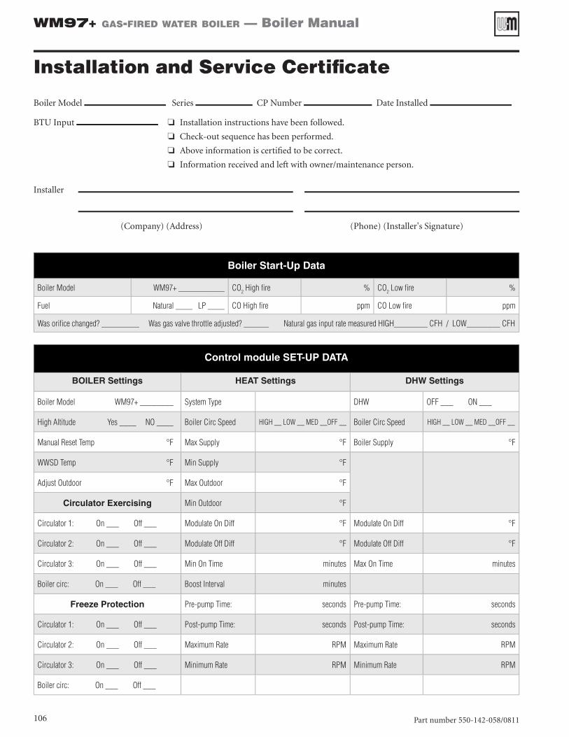
Boiler Model Series CP Number Date Installed
BTU Input ❏ ❏❏❏Installation instructions have been followed.
❏ ❏ ❏ ❏ ❏ ❏❏❏Check-out sequence has been performed.
❏ ❏ ❏ ❏ ❏ ❏❏❏Above information is certified to be correct.
❏ ❏ ❏ ❏ ❏ ❏❏❏Information received and left with owner/maintenance person.
Installer
(Company) (Address) (Phone) (Installer's Signature)
Installation and Service Certificate
Boiler Start-Up Data
Boiler Model WM97+ ___________ CO2 High fire % CO2 Low fire %
Fuel Natural ____ LP ____ CO High fire ppm CO Low fire ppm
Was orifice changed? _________ Was gas valve throttle adjusted? ______ Natural gas input rate measured HIGH________ CFH / LOW________ CFH
Control module SET-UP DATA
BOILER Settings HEAT Settings DHW Settings
Boiler Model WM97+ ________ System Type DHW OFF ___ ON ___
High Altitude Yes ____ NO ____ Boiler Circ Speed HIGH __ LOW __ MED __OFF __ Boiler Circ Speed HIGH __ LOW __ MED __OFF __
Manual Reset Temp °F Max Supply °F Boiler Supply °F
WWSD Temp °F Min Supply °F
Adjust Outdoor °F Max Outdoor °F
Circulator Exercising Min Outdoor °F
Circulator 1: On ___ Off ___ Modulate On Diff °F Modulate On Diff °F
Circulator 2: On ___ Off ___ Modulate Off Diff °F Modulate Off Diff °F
Circulator 3: On ___ Off ___ Min On Time minutes Max On Time minutes
Boiler circ: On ___ Off ___ Boost Interval minutes
Freeze Protection Pre-pump Time: seconds Pre-pump Time: seconds
Circulator 1: On ___ Off ___ Post-pump Time: seconds Post-pump Time: seconds
Circulator 2: On ___ Off ___ Maximum Rate RPM Maximum Rate RPM
Circulator 3: On ___ Off ___ Minimum Rate RPM Minimum Rate RPM
Boiler circ: On ___ Off ___

Part number 550-142-058/0811 107
WM97+ gas-fired water boiler — Boiler Manual
Customer Info: Maintenance Info:Contact: Name:
Contractor: Phone:Job name: Model:City, state: CP#:Distributor: Installed:
System Components: Boiler/System Piping Details (Please Sketch)Near boiler pipe size: Top: _____ Bottom (DHW): _____
Boiler circulator speed:HEATING: HIGH __ LOW __ MED __OFF __DHW: HIGH __ LOW __ MED __OFF __
DHW tank (yes/no):DHW direct/system:
DHW model:DHW pipe size:
DHW circulator model:Is there air in system?:
Diagnostic Errors:Control fault:
Ignition retries:Manal reset CNT:
Auto reset CNT:
Software Versions:Display:
Main micro:Second micro:
Lockout History #1 Lockout History #2 Lockout History #3HH:MM MM/DD/YY: HH:MM MM/DD/YY: HH:MM MM/DD/YY:
Status: Status: Status:Manual reset: Manual reset: Manual reset:
If yes-description: If yes-description: If yes-description:Auto reset: Auto reset: Auto reset:
If yes-description: If yes-description: If yes-description:Temperatures: Temperatures: Temperatures:
Status: Status: Status:Boiler out 1: Boiler out 1: Boiler out 1:Boiler out 2: Boiler out 2: Boiler out 2:
Boiler in 1: Boiler in 1: Boiler in 1:Flue 1: Flue 1: Flue 1:Flue 2: Flue 2: Flue 2:
Outdoor: Outdoor: Outdoor:Inputs: Inputs: Inputs:
Status: Status: Status:Input 1: Input 1: Input 1:Input 2: Input 2: Input 2:Input 3: Input 3: Input 3:
Manual limit: Manual limit: Manual limit:Auto limit: Auto limit: Auto limit:
Low WTR Cutoff: Low WTR Cutoff: Low WTR Cutoff:Blower tach: Blower tach: Blower tach:
Flame signal: Flame signal: Flame signal:Outputs: Outputs: Outputs:
Status: Status: Status:Gas valve: Gas valve: Gas valve:
Boiler circulator: Boiler circulator: Boiler circulator:Circulator 1: Circulator 1: Circulator 1:Circulator 2: Circulator 2: Circulator 2:Circulator 3: Circulator 3: Circulator 3:
Blower signal: Blower signal: Blower signal:Alarm: Alarm: Alarm:
WM97+ Gas Boiler Data Collection Sheet

108
WM97+ gas-fired water boiler — Boiler Manual
Recommended