CI-2001A/BWeighing Indicator
OWNER’S MANUAL

CONTENTSPRECAUTIONS 4INTRODUCTION 6 THE FEATURES OF CI-2001A/B 6TECHNICAL SPECIFICATION 7DIMENSIONS 8FRONT PANEL(CI-2001A) 9FRONT PANEL(CI-2001B) 11REAR PANEL 13 INSTALLATION 14TEST MODE 15CALIBRATION MODE 18SET MODE 21SERIAL INTERFACE 25ERROR MESSAGE AND TROUBLE SHOOTING 29

4
PRECAUTIONS
Place the indicator on a flat and stable surface.
Do not use inflammable materials incleaning.
Do not severely press because the lightpressing of keys can incite the operation.
Keep the main body from rain andkeep in dry area.
5
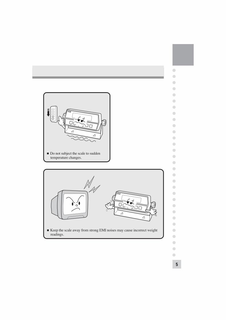
Do not subject the scale to sudden temperature changes.
Keep the scale away from strong EMI noises may cause incorrect weight readings.

6
INTRODUCTION
THE FEATURES OF CI-2001A/B
We greatly appreciate your purchase of the CAS industrial indicator. Thesegoods perform excellently and exhibit splendid properties through strike tests. CAS indicator (CI-series) is delicately designed to coincide with the specialrequirements of several industrial fields and includes many functions and variousexternal interfaces. Also, it is programmed for the user's convenience andcontains help display functions that are easily accessible. Before using CI-2001A/B, It is recommended that you read this manualcarefully so you may use this device to its full potential.
1. FeaturesAppropriate for weight and measurement system.Easy operation and various options.Simple full digital calibration. (SPACTM : single pass automatic span calibration)WATCHDOG circuitry (system restoration).Weight back-up (power on actual weight).Wall mount type (CI-2001A/B) - standardPanel mount type (CI-2001A/B(P)) - optional
2. Main FunctionVarious specification of weight conversion speed. (Digital Filter Function)Various printer connection. (RS232 Serial printer - optional)Users can set the max. weight which users want to and division at one's disposal.Self hardware test. Prompt A/S is available for test of each part of the module.

7
TECHNICAL SPECIFICATION
DC 5V, up to 4 350 load cells
20mV, including dead load
0.05mV 5mV
2 V/D(NTEP, OIML)
0.5 V/D(Non NTEP, OIML)
Within 0.01% of FS
Approximately 200,000 counts
5,000 dd(NTEP, OIML)30,000 dd(Non NTEP, OIML)
10 times/sec
Load cell excitation voltage
Full scale input signal
Zero adjust range
Input sensitivity
System linearity
A/D internal resolution
A/D external resolution
A/D conversion speed
Analog Part
Span calibration
Display
Size of letter
Display below zero
Additional symbols
AC adapter
Power consumption
Operating temperature
Overall dimensions
Weight
Digital Part
Full Digital Calibration: SPACTM
(Single pass automatic span calibration)
CI-2001A LED(6 digit)
CI-2001B LCD(5 digit)
CI-2001A 14mm(Height)
CI-2001B 25mm(Height)
"-" minus signal
CI-2001AZero, Tare, Gross, Net, Stable, lb, kg
CI-2001B Zero, Net, Stable, lb, kg
AC 110V/220V(DC 12V, 850mA)
CI-2001A 10W
CI-2001B 1W
-10°C 40°C
85mm 186mm 58mm
0.5kg
8
Serial Interface: RS-232
Serial Interface: RS-422/485
Panel Mount Bracket
Inner Clock (only CI-2001B)
Standard
Option-1
Option-2
Option-3
Option Part
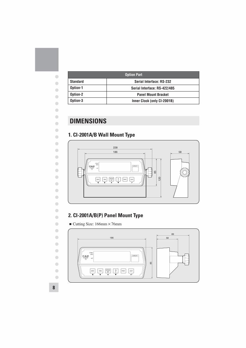
DIMENSIONS
1. CI-2001A/B Wall Mount Type
58228186
8512
0STABLE
ZERO
NETCI-2001BIII
ZERO TARE PRINT LIGHT
CAPACITY
GROSSNET
kglb
2. CI-2001A/B(P) Panel Mount TypeCutting Size: 166mm 76mm
186
85
8958
STABLEZERO
NETCI-2001BIII
ZERO TARE PRINT LIGHT
CAPACITY
GROSSNET
kglb

9
FRONT PANEL(CI-2001A)
ZEROTARE
GROSSNET
CI-2001A
CAPACITY
ZERO TARE PRINT ENTERGROSSNET
kglb
STABLE
lbkg
III
1. Display lamp( )lb lamp: ON when the weight unit is pound [lb]kg lamp: ON when the weight unit is kilogram [kg]STABLE lamp: ON when the weight is stable.TARE lamp: ON when the tare weight is stored.GROSS lamp: ON when the current weight is GROSS weight.NET lamp: ON when the current weight is NET weight.ZERO lamp: ON when the current weight is 0kg(0lb).
2. Keyboard
Available keys instead of numeric keys.: Change the set value.
Increase the first place value to 1.Usage-input the numeric value in TEST, CAL, SET mode.
: Change the digit of the set value.Move to the left by 1 place.Usage-input the numeric value in TEST, CAL, SET mode.
Returns the display to 0.ZERO

10
Use container in weighing.Current weight is memorized as tare weight.If you press TARE key in unload condition, Tare setting is released automatically.
Use this key to switch from gross to net weight.GROSS lamp on - gross weightNET lamp on - net weightIn case tare weight is REGISTERED, tare and item's total weight is G. weight and only item's weight is N. weight.
Toggles between lb and kg units.
Used to print the present weighing value.
Total weighing value print key.HOLD key.In CALIBRATION, TEST, SET mode.: Store current condition and exit.Set in F09.
3. How to enter TEST modeTurn on the power while pressing the "PRINT" key and TEST mode starts.
4. How to enter SET modeTurn on the power while pressing the "ENTER( )" key and SET mode starts.
5. How to enter CAL modeTurn on the power while pressing the CAL switch on the rear panel of the indicator and CAL mode starts.
TARE
GROSS/NET
kg/lb
ENTER

11
FRONT PANEL(CI-2001B)
1. Display lamp( )lb lamp: ON when the weight unit is pound [lb]kg lamp: ON when the weight unit is kilogram [kg]STABLE lamp: ON when the weight is stable.ZERO lamp: ON when the current weight is 0kg(0lb).NET lamp: ON when the current weight is NET weight.
2. Keyboard
Available keys instead of numeric keys.: Change the set value.
Increase the first place value to 1.Usage-input the numeric value in TEST, CAL, SET mode.
: Change the digit of the set value.Move to the left by 1 place.Usage-input the numeric value in TEST, CAL, SET mode.
Returns the display to 0.ZERO
12
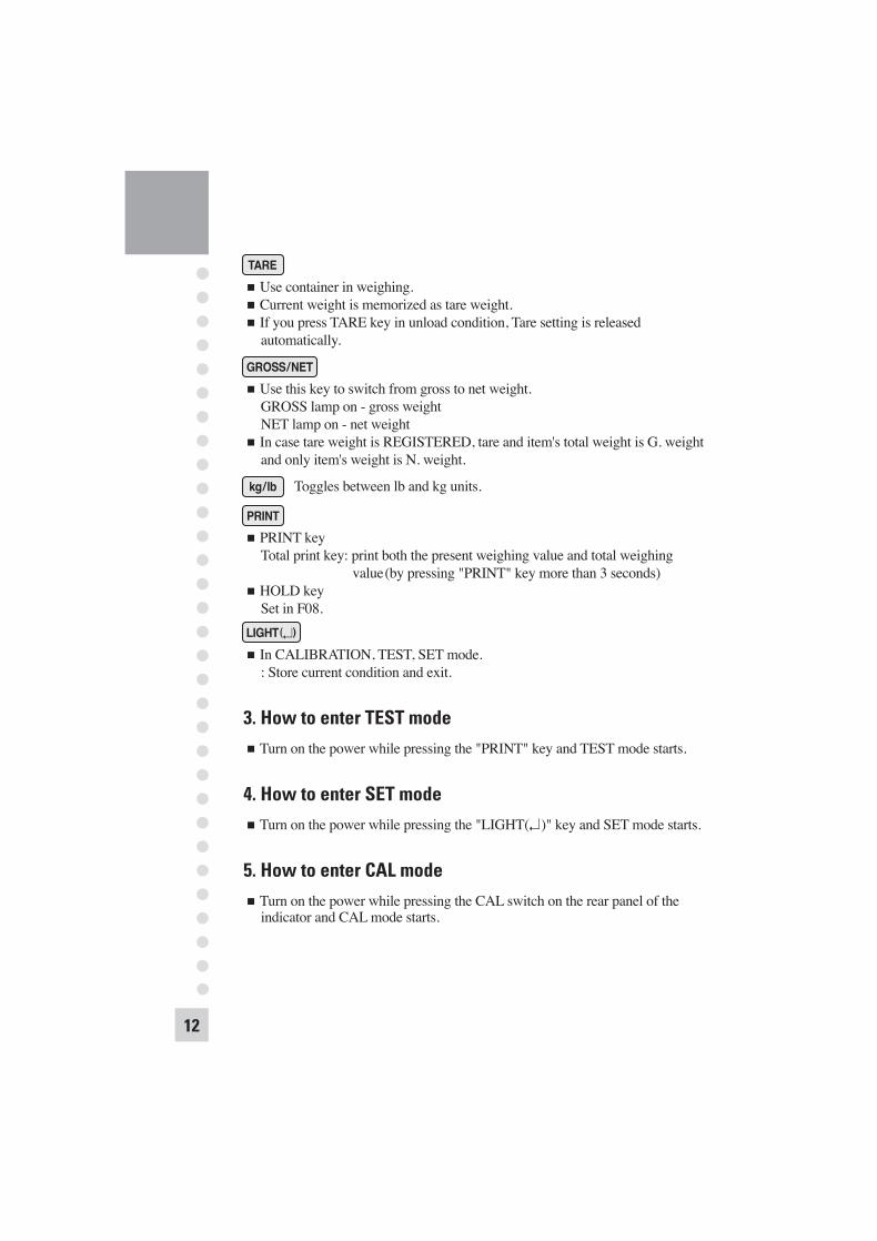
Use container in weighing.Current weight is memorized as tare weight.If you press TARE key in unload condition, Tare setting is released automatically.
Use this key to switch from gross to net weight.GROSS lamp on - gross weightNET lamp on - net weightIn case tare weight is REGISTERED, tare and item's total weight is G. weight and only item's weight is N. weight.
Toggles between lb and kg units.
PRINT keyTotal print key: print both the present weighing value and total weighing
value(by pressing "PRINT" key more than 3 seconds)HOLD keySet in F08.
In CALIBRATION, TEST, SET mode.: Store current condition and exit.
3. How to enter TEST modeTurn on the power while pressing the "PRINT" key and TEST mode starts.
4. How to enter SET modeTurn on the power while pressing the "LIGHT( )" key and SET mode starts.
5. How to enter CAL modeTurn on the power while pressing the CAL switch on the rear panel of the indicator and CAL mode starts.
TARE
GROSS/NET
kg/lb
LIGHT( )

13
REAR PANEL
RS-232C PORT: Serial interface port. (computer, printer)LOAD CELL: Port for connecting load cell.DC ADAPTER: Port for DC power.(DC 12V adapter are available)CAL S/W: Using in calibration starts.ON/OFF: Power ON/OFF switch.
Legal seal installedInstall the seal on the wire loop as shown in below figure.
Cal Switch Plate
Legal SealRear Cover
Sealing Bolt

14
INSTALLATION
1. Load Cell ConnectionConnect load cell connector to load cell port which is in the backside of indicator.
Connecting method
1
23 4
5
6
SHLD
LOADCELL 1CONNECTOR
EX +
EX -
SIG + SIG -
Ref. Each L/C manufacturer's or model's wire color could be different. In that case, please note the following diagram on next page.
Resolution to load cell output rate
Load cell Output voltage for 5V excitation voltage Recommended resolution
2mV 1/1,0004mV 1/2,000
10mV 1/5,000
Manufacturer's wire colors
N0. 1 No. 2 No. 3 No. 4 No.5(EX ) (EX ) (SIG ) (SIG ) (SHIELD)
Red White Green Blue ShieldRed Black Green White ShieldRed Black Green White ShieldRed Black Green White Shield
Green Black White Red YellowRed Blue White Black ShieldRed Black Green White ShieldRed White Green Blue YellowRed Black White Green ShieldRed Blue White Black Yellow
Green Black Red White Shield
CompanyCASKYOWAINTERFACEP.TBLHSHOWASHINKOHTMITMLTFACHUNTLEIGH
Connector

15
TEST MODE
1. How to EnterTurn on the power while pressing the "PRINT" key and TEST MODE starts.(CI-2001A/B kg/lb version)Turn on the power while pressing the " " key and TEST MODE starts.(CI-2001A/B kg only version)
2. Available Keys
Increase the first place set value to 1.
Move to the left by 1 place of the set value.
Move into next test menu.(CI-2001A)
Move into next test menu.(CI-2001B)
3. Test Menu(TEST 1 - TEST 5)TEST 1: Key testTEST 2: LCD display testTEST 3: Load cell test and A/D conversion testTEST 4: Serial Interface test(RS-232)TEST 5: Printer test
TEST 1Function: Key test
ENTER
LIGHT( )
Key Display Description
LIGHT( ): Move to next test
other keys: perform test
TEST 1 condition.
Press the key to be tested and the No, and code of the key is displayes.
Key mode should be identify with code of key like above.

16
CI-2001A CI-2001BKey mode Code Key mode Code
ZERO 1 ZERO 1TARE 2 TARE 2G/N 3 G/N 3
PRINT 4 kg/lb 45 PRINT 5
<Key list>
TEST 2Function: LCD display test
Key Display Description
Displaying all lampsof key
TEST 2 condition.
TEST 2 is performed automatically after 3 seconds or so.
Key Display Description
LIGHT( ): Move to next test
other keys: perform test
TEST 3 condition.
Display digital value of current weight.This value means converted digital value.
REF 1. Program is automatically shifted to Test 3 after completing Test 2.
TEST 3Function: A/D converter test(L/C test)
REF 1. A/D converter test is automatically completed by displaying converted digital value of current weight.
REF 2. L/C test is also completed by loading the weight on the platform.Check whether digital value is changing.If the digital value is fixed or zero is displayed, please check the connection of the load cell.
Digitalconvertedvalue

17
TEST 4Function: RS-232 test with computer
Key Display Description
ZERO: Transmit '1'TARE : Transmit '2'G/N : Transmit '3'kg/lb : Transmit '4'
: Transmit '5'LIGHT( ): Next
menu
TEST 4 condition.Wait for transmission and reception.
Received: 1, Transmitted: none
Received: 1, Transmitted: 13
REF 1. Do this test after the connection between serial port of computer and serial port of indicator.
REF 2. Send No.1 in computer keyboard and check if indicator receives no.1.Send No.1 in indicator keyboard and check if computer receives no.1.
REF 3. Do this test after baud rate is specified in SET mode(F11).
INDICATOR TEST(when it isn't connected with PC)1)Connect directly between No.2(TXD) and No.3(RXD) in indicator of serial
port.2)If transmitting data is identical with receiving data by pressing key of front
panel, this test will be done.
TEST 5Function: Printer test
Key Display Description
LIGHT( ): Exit test mode
other keys: perform test
TEST 5 condition.
No error in printer.
Check printer connector.
REF 1. "GOOD" message is displayed if the printer connection and specification is done correctly. If or not, "ERROR 06" message is displayed.
REF 2. The test output format of printer is like follows.
TEST OK
If you press the enter key, it will be returned to NORMAL MODE.However, only when it is connected with printer, this test can be performed.

18
CALIBRATION MODE
1. How to EnterTurn on the power while pressing the CAL switch on the rear panel of the indicatorand CAL mode starts.
2. Available Keys
Increase the first place set value to 1.
Move to the left by 1 place of the set value.
Initial('0') of the set value.(kg/lb version)
Initial('0') of the set value.(kg only version)
Move into next menu.(CI-2001A)
Move into next menu.(CI-2001B)
3. Calibration Menu(CAL 1 - CAL 5)CAL 1: Maximum capacity SetCAL 2: Minimum division SetCAL 3: Setting weight in span calibrationCAL 4: Zero CalibrationCAL 5: Span Calibration
ENTER
LIGHT( )
Key Display Description
: Increase of no.: Shift of digit
LIGHT( ): Store and move into next menu
Program version.
CAL 1 condition.
100kg/lb
Maximum CapacityValue
CAL 1Function: Maximum Capacity SetRange 1 ~ 999,999kg/lb(CI-2001A)
1 ~ 99,999kg/lb(CI-2001B)
EX:
REF 1. The maximum capacity means the maximum weight that scale can measure.

19
Key Display Description
:Input the nextdivision
LIGHT( ): Store and move into next menu
CAL 2 condition.
0.01kg/lb
Minimum DivisionValue
EX:
Key Display Description
: Increase of no.: Shift of digit
LIGHT( ): Store and move into next menu
CAL 3 condition.
100kg/lb
Setting Weight
EX:
CAL 2Function: Minimum Division SetRange 0.0005 ~ 100kg/lb
REF 1. The minimum division means the value of one division. REF 2. External resolution is obtained by division the min. division by the
maximum capacity. Set the resolution to be within 1/30,000.
CAL 3Function: Setting Weight In Span CalibrationRange 1 ~ 999,999kg/lb(CI-2001A)
1 ~ 99,999kg/lb(CI-2001B)
REF 1. The weight shall be within the range of 10% ~ 100% of maximum weight. REF 2. The setting weight must be over the range of 10% of maximum weight.
If or not, error message ("ERR 22") will occur.REF 3. If the setting weight over the maximum capacity, error message ("ERR 23")
will occur.

20
Key Display Description
LIGHT( ): Zero calibration and move into next menu
CAL 4 condition.
Unload the tray and press ENTER/LIGHT( ) KEY
Under zero calibration
Zero calibration is completed.
converted digitalvalue
checking 33333indicator 22222
11111
CAL 4Function: Zero calibration
REF 1. If zero calibration is done without any error, GOOD message is displayedand program moves into CAL 5 automatically.
REF 2. If the "ZERO" key is pressed, only zero calibration is completed and program moves SAVE & EXIT mode. Press ENTE R/LIGHT( ) key.
CAL 5Function: Span calibration
REF 1. If zero calibration is done without any error, GOOD message is displayedthe weight of setting weight is displayed on LCD screen.Check the weight.
REF 2. If the span value is low. Error message (ERR 24) is displayed. Calibrate with lower resolution.
Key Display Description
LIGHT( ): Span calibration and move into next menu
CAL 5 condition.
Load the weight which was set in CAL 3 and press LIGHT( ).
Under span calibration
Span calibration is completed.
Press LIGHT( ) key.(Save & exit CAL mode)
converted digitalvalue
checking 33333indicator 22222
11111
SAVE

21
SET MODE
1. How to EnterTurn on the power while pressing the LIGHT( ) key and SET Mode starts.(CI-2001B)Turn on the power while pressing the ENTER( ) key and SET Mode starts.(CI-2001A)
2. Available Keys
Increase the first place set value to 1.
Move to the left by 1 place of the set value.
Move into next menu.(CI-2001A)
Move into next menu.(CI-2001B)
3. Set Value Conversion Menu(F01 - F14)F01 Select the primary base unit(only kg/lb version)F02 Designation of serial port usageF03 Automatic zero tracking compensationF04 Digital filterF07 Weight back-up(power-on actual weight)F08 " " key usage(CI-2001A kg version)F08 "PRINT" key usage(CI-2001B kg/lb version)F09 "ENTER" key usage(CI-2001A kg version)F09 " " key usage(CI-2001B kg version)F10 Device IDF11 Designation of serial interface baud rateF12 Designation of serial interface output modeF13 Set HOLD typeF14 Select of clock option(only CI-2001B)
ENTER
LIGHT( )
Select the primary base unit0 Primary unit is kg1 Primary unit is lbF01

22
Serial port usage0 Connection with computer and sub-display(CD-3000A)1 Connection with serial printerF02
Select the weight back-up mode0 Weight back-up is off (Power on zero)1 Weight back-up is on (Display setting weight)F07
"PRINT" key usage(CI-2001B kg/lb version)0 Not used
1- Print key(Press "PRINT" key)- Total print key(by pressing "PRINT" key more than 3 second)
2 HOLD key
F08
"* " key usage(CI-2001A kg version)0 Not used1 Total print keyF08
Automatic zero tracking0 None automatic zero
1 1 : 0.5 division ~ 9 9 : 4.5 division
F03 Autozero tracking will automatically bring the display back to "0" when there are small deviations.
Digital filter0 None automatic zero
1 1 : Less vibration ~ 9 9 : Much vibration
F04 Adjust the set value according to the condition how many times converted digital value read and display.

23
"ENTER" key usage(CI-2001A kg version)
0 Not used1 Total print key2 HOLD key
F09
"* " key usage(CI-2001B kg version)0 Not used1 Total print key2 HOLD key
F09
Device ID
00 : Device ID "00"00 (setting when it isn't
connected with system)~
99 99 : Device ID "99"
F10 It is used the no. of indicator when system is connected.
Baud rate(unit of speed in data transmission)0 600 bps (bit per second)1 1200 bps 2 2400 bps3 4800 bps4 9600 bps5 19200 bps
F11
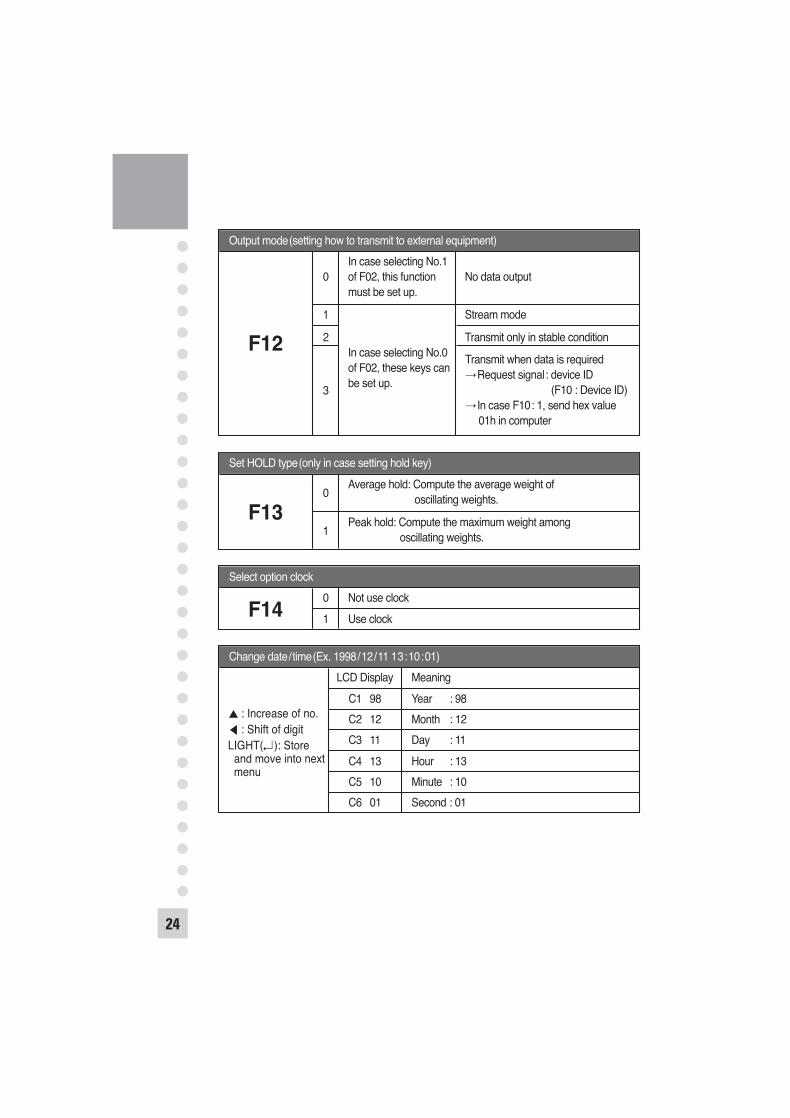
Set HOLD type(only in case setting hold key)
0Average hold: Compute the average weight of
oscillating weights.
1Peak hold: Compute the maximum weight among
oscillating weights.
F13
Select option clock0 Not use clock1 Use clockF14
24
Output mode(setting how to transmit to external equipment)In case selecting No.1
0 of F02, this function No data outputmust be set up.
1 Stream mode
2 Transmit only in stable conditionIn case selecting No.0of F02, these keys can
3 be set up.
F12Transmit when data is required
Request signal: device ID(F10 : Device ID)
In case F10: 1, send hex value01h in computer
Change date/time(Ex. 1998/12/11 13:10:01)LCD Display Meaning
C1 98 Year : 98C2 12 Month : 12C3 11 Day : 11C4 13 Hour : 13C5 10 Minute : 10C6 01 Second : 01
: Increase of no.: Shift of digit
LIGHT( ): Store and move into next menu

25
RXD 3TXD 2GND 7
2 Transmit Data3 Receive Data 7 Signal Ground4 Request To Send 5 Clear To Send6 Data Set Ready 8 Carrier Detect
20 Data Terminal Ready
SERIAL INTERFACE
RS232C Port Connection
25pin port(Female)Serial port of Computer
9pin port(Male)RS-232C port of CI-2001A/B
RXD 3TXD 2GND 7
3 Transmit Data2 Receive Data 5 Chassis Ground1 Carrier Detect 4 Data Terminal Ready6 Data Set Ready 7 Request to Send8 Clear to Send
9pin port(Female)Serial port of Computer
9pin port(Male)RS-232C port of CI-2001A/B
OP-1 RS232C Serial Interface (COM1)
Sub-display Connection
RXD 3TXD 2GND 7
2 Transmit Data3 Receive Data 7 Signal Ground
9pin port(Male)RS-232C port of sub-display
9pin port(Male)RS-232C port of CI-2001A/B

Data Format, , , CR LFData(8 byte)
US(Unstable)ST(Stable) OL(Over)
GS(Gross)NT(Net)
UNIT
kglb
Device ID
Empty
Device ID Transmit 1 byte device ID so that the receiver can receive data selectivelywhich indicator send.
Weight data(8 byte)1. 13.5 kg : '0 ', '0 ', '0 ', '0 ', '1 ', '3 ', ' . ', '5 '2. 135 kg : '0 ', '0 ', '0 ', '0 ', '1 ', '3 ', '5 ', '0 '3. -135 kg : ' - ', '0 ', '0 ', '0 ', '0 ', '3 ', '5 ', '0 'Each ASCII code of weight transmitted by 8 byte.('0 ' : 0 20)
Simple Interface Program(GWBASIC Language)10 OPEN “COM1:9600,N,8,1” As #120 IF LOC(1) = 0 THEN 6030 A$ = INPUT$(1,1)40 PRINT A$ ; “ ”;50 GOTO 2060 B$=INKEY$ : IF B$ =“ ” THEN 2070 PRINT B$ ; “ ”;80 PRINT #1,B$;90 GOTO 20
26

27
Simple Interface Program(GWBASIC Language)#include <bios.h>#include <conio.h>#define COM1 0#define DATA_READY 0 100#define TRUE 1#define FALSE 0#define SETTINGS 0 E3
int main(void) {
int in, out, status, DONE = FALSE;
bioscom(0, SETTINGS, COM1); cprintf(“... BIOSCOM [ESC] to exit ... n”);while (!DONE) {
status = bioscom(3, 0, COM1);if (status & DATA_READY)
if ((out = bioscom(2, 0, COM1) & 0 7F) != 0) putch(out);
if (kbhit( )) {
if ((in = getch( )) == ‘ 1B’) DONE = TRUE;
bioscom(1, in, COM1); }
}return 0;
}
CP-7000 Series Printer Connection
RXD 3TXD 2GND 7
2 Transmit Data3 Receive Data
14 Signal Ground
15pin port(Female)CP-7000 series printer port
9pin port(Male)RS-232C COM1 port of
CI-2001A/B

ND Series Serial Printer Connection
RXD 3TXD 2GND 7
3 Transmit Data2 Receive Data 7 Signal Ground
9pin port(Male)ND series serial printer port
9pin port(Male)RS-232C COM1 port of
CI-2001A/B
Transmit mode: Same as RS-232C interface COM1Data format: Same as RS-232C interface COM1Connecting method of RS-485 Port
SPECIAL RS-422/485 Serial Interface (COM1)
Connecting method of RS-485 Remote Sub Display
IN(+) 1OUT(-) 4IN(-) 5OUT(+) 6GND 7
2 Transmit Data(+)15 Receive Data(-) 14 Transmit Data(-)3 Receive Data(+) 1 Ground7 Ground 4,5,6,8 wire connect.16,17,18,19 wire connect.
25pin portSerial port of computer
RS-485 port of CI-2001A/B(9pin D-type male connector)
IN(+) 1OUT(-) 4IN(-) 5OUT(+) 6GND 7
6 Transmit Data(+)5 Receive Data(-)4 Transmit Data(-)1 Receive Data(+)7 Ground
RS-485 port of sub-displayRS-485 port of CI-2001A/B(9pin D-type male connector)
28

29
ERROR MESSAGE AND TROUBLE SHOOTING
1. Error in Weighing ModeErr 02
Reason: Failure in load cell connection or error in A/D conversion part.Trouble shooting: Check the load cell connector so that you may see if
the polarity of signal is reversed.
Err 06Reason: Error in printer connectionTrouble shooting: Check with printer connector.
If there is no problem with printer and printer connector, please request A/S to head office.
Err 08Reason: The ZERO key or TARE key is adjusted not to be operated under
the unstable condition.Trouble shooting: Press ZERO or TARE key in stable condition.
Err 09Reason: Current weight deviates from zero range.Trouble shooting: Press the ZERO key within 10% of the maximum capacity.
Err 10Reason: Tare weight exceeds the maximum capacity of the scale. Trouble shooting: Set the tare to be smaller than the maximum capacity.
Otherwise the maximum capacity is reset to be larger than the tare to be set in the calibration menu, and reset the calibration using weight.
Err 13Reason: The zero range deviates from the set range. Trouble shooting: Confirm that there is nothing on the weighing platform.
If there were nothing, do calibration on CAL mode.
OverReason: The weight on platform is too heavy to be measured. Trouble shooting: Do not load the item exceeds the maximum tolerance.
If the load cell is damaged, the load cell should be replaced.

2. Errors in Calibration ModeErr 21
Reason: The resolution is set to be exceeded the limit 1/10,000.Trouble shooting: Lower the resolution.
The resolution = allowed weight/one division Modify the allowed weight in CAL 1 or modify the divisionin CAL 2 so that the resolution should be below 1/10,000.
Err 22Reason: The weight for span calibration is set to be lower than 10% of the
maximum capacity of the scale.Trouble shooting: Set the weight for span calibration in CAL 3 to be more than
10% of the maximum capacity.
Err 23Reason: The weight for span calibration is set to be exceeded 100% of the
maximum capacity of the scale.Trouble shooting: Set the weight for span calibration to be within the
maximum capacity of the scale in CAL 1.
Err 24Reason: The load cell output is too low at SPAN calibration. Trouble shooting: Setting of current resolution is not possible due to the error
in load cell. Proceed calibration again with less resolution.
Load Cell Output Voltage Recommended Resolutionfor 5V Excitation Voltage2mV 1/1,0004mV 1/2,00010mV 1/5,000
Err 25Reason: The load cell output is too high at SPAN calibration. Trouble shooting: Setting of current resolution is not possible due to the error
in load cell.Proceed calibration again with less resolution.
30

31
Err 26Reason: The load cell output is too high at ZERO calibration. Trouble shooting: Check if the platform empty.
Proceed calibration again after checking in A/D TEST mode.
Recommended