Weather Sensing and Laser Communications for NanosatellitesKerri Cahoy, MIT AeroAstro

Why Space? Above the Atmosphere
2
[http://www.ipac.caltech.edu/outreach/Edu/Windows/irwindows.html]
11/4/2015

Above the Atmosphere
3
[http://www22.homepage.villanova.edu/rex.saffer/SESAME/radiation_files/transatmos.jpg]
11/4/2015
Overview
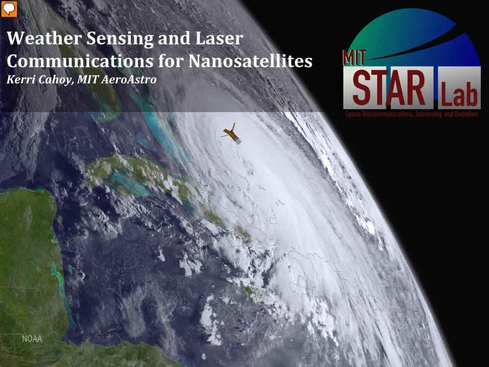
• Introduction– CubeSats 101
• Communications– NODE
• Laser communication downlink
• Laser Occultation– Bending angle and T,P profile
recovery• GPS Radio Occutlation for
validation
NanoRacks deployment of MicroMAS from the ISS Japanese Experiment Module Remote Manipulator System (JEMRMS). Photo courtesy NASA/NanoRacks
411/4/2015

Satellite Classification
•Small Satellite < 500 kg (all wet mass)•Microsatellite 10 –100 kg•Nanosatellite 1 — 10 kg•Picosatellite 0.1 kg – 1 kg•Femtosatellite < 0.1 kg•CubeSat 1U 10 cm x 10 cm x 10 cm cube•1U as a building block•1.5U, 2U, 3U, 6U, 12U…
11/4/2015 5

CubeSats 101
6
• On the scene in 1999– Jordi Puig-Suari (Cal Poly SLO)– Bob Twiggs (Stanford)– “OPAL” Orbiting Picosatellite Automatic
Launcher – Too complicated– “Beanie babies” vs. “Klondike bars”
• 1 standard CubeSat unit (1U) – Volume: 10 x 10 x 10 cm– Mass: < 1.33 kg– Common sizes: 1U, 1.5U, 2U, 3U… – Now 6U… 12U?
• Low cost and short development time
• Increased accessibility to space
https://directory.eoportal.org/web/eoportal/satellite-missions/o/opal, credit SSDL
11/4/2015

CubeSat Design Specification
711/4/2015

Tall, Grande, Venti…
8
http://ccar.colorado.edu/asen5050/projects/projects_2013/Naik_Siddhesh/Cubesat.JPG
Pumpkin, Inc. Motherboard
11/4/2015

Poly-Picosatellite Orbital Deployer
9
http://www.nasa.gov/centers/ames/images/content/152693main_genebox-015.jpg
11/4/2015

Launch integration on Rocket
10
CubeSat deployment pods on top of the Bion-M1 spacecraft: BeeSat-2, BeeSat-3 and SOMP in front;OSSI-1 (1U) in a 3U-Pod back left; DOVE-2 (3U) in back right. http://amsat-uk.org/tag/beesat-2
11/4/2015

Launch from Space Station
11
• Deliver to NanoRacks• Get integrated into NRCSD• Get integrated into Cargo• Cargo integrated into Cygnus• Cygnus shipped to launch site• Cygnus integrated into rocket• Antares launch• Cygnus separation• Cygnus rendezvous with ISS• Cygnus unpacked• Cargo unpacked• NRCSD integrated to slide table• Slide table through airlock• NRCSD onto JEMRMS• Deployment Cygnus being unberthed from Harmony module
http://www.flickr.com/photos/nasa2explore/12644390754/
11/4/2015
1211/4/2015

1311/4/2015

1411/4/2015
1511/4/2015

16
• Space is hard– Rocket acoustic/phys vibe– Rockets can fail/explode– It’s far away– Vacuum – Microgravity– Hot / cold temp. swings– Radiation / solar storms– Things break – a lot– Hard to find small objects– Lots of safety paperwork– Expensive to get there– Expensive ground staff
11/4/2015

17
• Space is hard– Rocket acoustic/phys vibe– Rockets can fail/explode– It’s far away– Vacuum – Microgravity– Hot / cold temp. swings– Radiation / solar storms– Things break – a lot– Hard to find small objects– Lots of safety paperwork– Expensive to get there– Expensive ground staff
• Space is also awesome– Helps us answer “why are
we here?”– Incredible ability to
observe Earth
11/4/2015
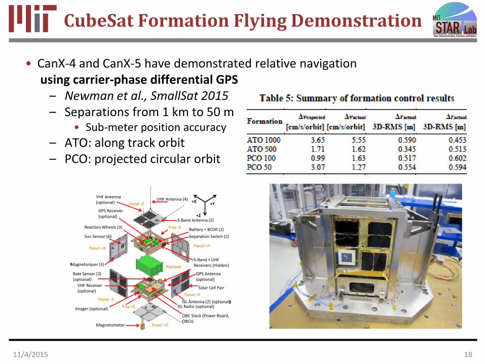
CubeSat Formation Flying Demonstration
• CanX-4 and CanX-5 have demonstrated relative navigationusing carrier-phase differential GPS
– Newman et al., SmallSat 2015– Separations from 1 km to 50 m
• Sub-meter position accuracy– ATO: along track orbit– PCO: projected circular orbit
1811/4/2015

CubeSat Inertial Pointing Capability
• A study of variability of massive, luminous stars and supernova
• BRITE (BRIght Target Explorer) Constellation
– 7 kg, 20 cm cube nanosatellites
– University of Toronto and collaborators
• Multiple satellites help with continuous viewing
• Different filters on satellites• Demonstrated up to 12 arcsec
RMS pointing over 15 min
http://utias-sfl.net/?page_id=407
11/4/2015 19

Fighting the “but, the tiny aperture” issue
• Utah State University Space Dynamics Laboratory “Petal”– Deployable Petal Telescope
20
• Autonomous rendezvous and docking for telescope re-configuration
• Low-cost active deformable mirrors
http://www.sdl.usu.edu/downloads/petal-telescope.pdf
11/4/2015
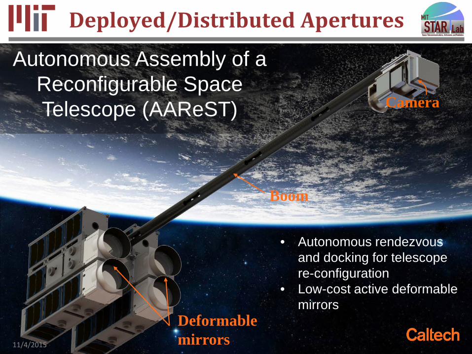
Deployed/Distributed Apertures
21
Camera
Autonomous Assembly of a Reconfigurable Space Telescope (AAReST)
• Autonomous rendezvous and docking for telescope re-configuration
• Low-cost active deformable mirrors
Boom
Deformable mirrors11/4/2015

Improved optical quality of apertures
•AAReST deformable mirrors for on deployables
2211/4/2015

Overview
• Introduction– CubeSats 101
• Communications– NODE
• Laser communication downlink
• Laser Occultation– Bending angle and T,P profile
recovery• GPS Radio Occutlation for
validation
NanoRacks deployment of MicroMAS from the ISS Japanese Experiment Module Remote Manipulator System (JEMRMS). Photo courtesy NASA/NanoRacks
2311/4/2015

Optical vs. RF
24
Radio Optical“Lasercom”
SpaceSegment
Radio modem,patch antenna
Laser transmitter,steering system
Spectrum / License
~MegahertzHeavily regulated
Terahertz availableUnregulated
GroundSegment
Large dish (20+ ft)and facility$1M and up
1 ft amateurastronomy telescope
$100k
Lasercom offers superior link efficiency (less power per bit) due to its ability to better direct signal to receiver.
11/4/2015

Comparison of RF and Optical
Opticalλ = 1000 nm
RF (10 GHz)λ = 3 cm
Units
TX Power (Pt) 0 0 dBW
TX Losses (Lt) -2 0 dB
TX Aperture (Gt) 119 30 dB
Path Loss (Lpath) -259 -169 dB
RX Aperture (Gr) 119 30 dB
RX Power (Pr) -23 -109 dBW
RX Sensitivity -97 -114 dBW
Margin 74 5 dB
11/4/2015 25
Optical system has a 70 dB advantage Adapted from: Caplan, D. “Free-Space Laser Communications”, 2008
• TX aperture is 30 cm• RX aperture is 30 cm
• Link range is 700 km (LEO)• Receiver sensitivities typical for 1 Gbps link
All system parameters are
matched, except wavelength

Calendar year
Num
ber o
f Sat
ellit
esMotivation
• Rapid growth of small satellite market• Increasing downlink demand from science payload• Limited capability from CubeSat RF systems
11/4/2015 26
CubeSat communication
capabilities2Number of small satellites (1-50 kg) launched per year1
Nanosatellite Optical Downlink Experiment (NODE)

NODE Architecture
11/4/2015 27
Low-rate RF link
Uplink beacon
Downlink beam
Downlink optical communication link (1550 nm)
Uplink optical beacon for PAT(850 nm)
Bi-directional low-rate RF link for telemetry and command
PAT = Pointing, Acquisition, and TrackingRF = Radio Frequency

Requirements Derivation
11/4/2015 28
Optical
power
SWaP = Size, Weight, and PowerADCS = Attitude Determination and Control System
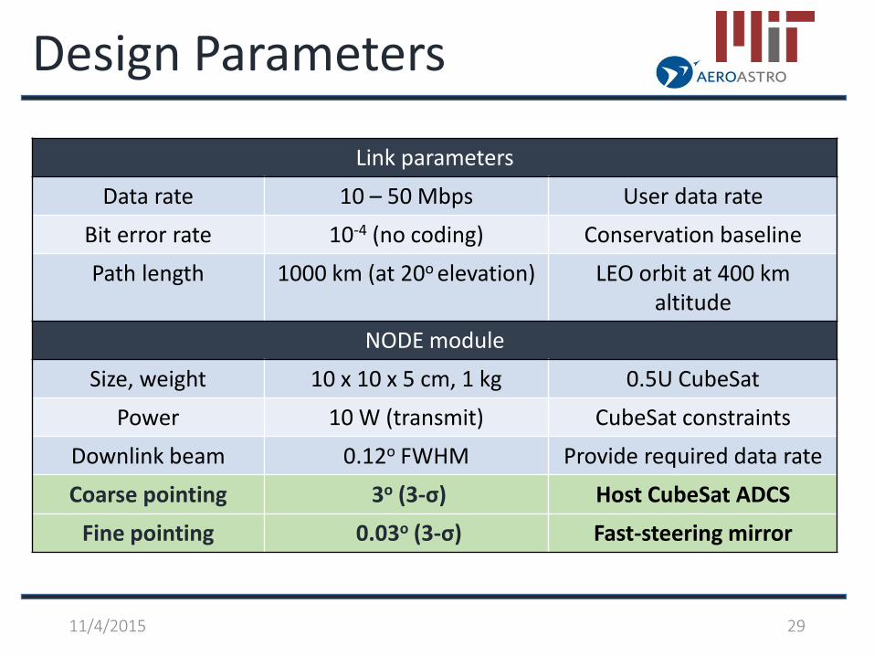
Design Parameters
Link parameters
Data rate 10 – 50 Mbps User data rate
Bit error rate 10-4 (no coding) Conservation baseline
Path length 1000 km (at 20o elevation) LEO orbit at 400 km altitude
NODE module
Size, weight 10 x 10 x 5 cm, 1 kg 0.5U CubeSat
Power 10 W (transmit) CubeSat constraints
Downlink beam 0.12o FWHM Provide required data rate
Coarse pointing 3o (3-σ) Host CubeSat ADCS
Fine pointing 0.03o (3-σ) Fast-steering mirror
11/4/2015 29
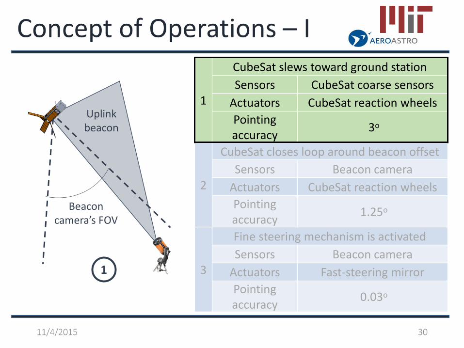
Concept of Operations – I
11/4/2015 30
1
Beacon camera’s FOV
Uplink beacon
1
CubeSat slews toward ground station Sensors CubeSat coarse sensors
Actuators CubeSat reaction wheels Pointing accuracy 3o
2
CubeSat closes loop around beacon offsetSensors Beacon camera
Actuators CubeSat reaction wheels Pointing accuracy 1.25o
3
Fine steering mechanism is activatedSensors Beacon camera
Actuators Fast-steering mirrorPointing accuracy 0.03o

Concept of Operations - II
11/4/2015 31
2
Beacon camera’s FOV
Uplink beacon
1
CubeSat slews toward ground station Sensors CubeSat coarse sensors
Actuators CubeSat reaction wheels Pointing accuracy 3o
2
CubeSat closes loop around beacon offsetSensors Beacon camera
Actuators CubeSat reaction wheels Pointing accuracy 1.25o
3
Fine steering mechanism is activatedSensors Beacon camera
Actuators Fast-steering mirrorPointing accuracy 0.03o

Concept of Operations - III
11/4/2015 32
3
Downlink beam
1
CubeSat slews toward ground station Sensors CubeSat coarse sensors
Actuators CubeSat reaction wheels Pointing accuracy 3o
2
CubeSat closes loop around beacon offsetSensors Beacon camera
Actuators CubeSat reaction wheels Pointing accuracy 1.25o
3
Fine steering mechanism is activatedSensors Beacon camera
Actuators Fast-steering mirrorPointing accuracy 0.03o
Beacon camera’s FOV
Uplink beacon
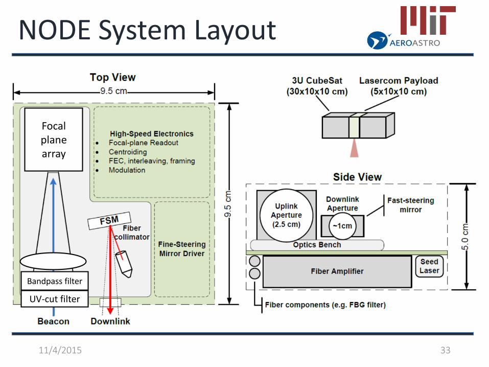
NODE System Layout
11/4/2015 33
UV-cut filter
Bandpass filter
Focal plane array

• Three-axis stabilized CubeSat ADCS• Common pointing capability: 1 – 5o RMS 2,4
[credit: Blue Canyon Tech]. [credit: Maryland Aerospace Inc.]
Coarse Control Stage
11/4/2015 34
Attitude Sensors Attitude ActuatorsSun sensors
MagnetometersEarth horizon sensors
Gyroscopes
Reaction wheelsMagnetorquers
Miniaturized reaction wheels Magnetorquers Earth horizon sensors

Fine Control Stage• MEMS fast steering mirror
• Mirrorcle Tech. Inc. • 2-axis tip/tilt • Range: ±1.25o
• No integrated feedback
11/4/2015 35
Repeatability TestResults
RMS error(best device)
0.0007°(12 μrad)
Pointing requirement
0.03o
(525 μrad)
Fast-steering mirror from Mirrorcle Tech.
Lab bench setup for FSM characterization
Test pattern

Transmitter Design Parameters
Parameter Value Notes/Justification
Size 10 x 10 x 2 cm
Allocation to the transmitter portion of the lasercom terminal.
Mass <300 g
Electrical Input Power < 8 W
Operating Temp. Range 0-40 C Typical CubeSat values
Optical Output Power >200 mW avg. Link budget, PPM-16 assumed
Modulation Type PPM, M=[8-64] ER implications, “power robbing”
Modulation BW > 1 GHz desired Future pointing improvements
Wavelength stability +/- 1 nm Ground receiver filter
11/4/2015 36

From Vodhanel, JLT 1990
• Challenge: achieving ER > 33dB with directly modulated laser (DML)– Needed to prevent “power robbing” in EDFA
• DML ER can be improved with narrow-band optical filtering via FM-AM conversion
Shirasaki, EL 1988; Vodhanel, JLT 1989 & 1990; Lee, PTL, 1996; Mahgerefteh, CLEO 1999 & PTL 2006; Caplan, JOFCR 2007, CLEO 2011 & 2014
• Typical DML FM response vs modulation frequency:
Transmitter Design Overview
11/4/2015 37

FPGA Modulation
• Electro-optic modulator not feasible in this design due to power constraints
• Direct FPGA drive demonstrated with Xilinx Spartan 6 FPGA evaluation board
– Adjustable: duty cycle, slot rate– GPIO drives 50 mA into 50 ohms
• SelectIO SERDES enables >600 MHz rates while maintaining low fabric clock rates
– Not using RocketIO/GTP interfaces power savings
PPM-16waveform(electrical)
5 ns pulses
11/4/2015 38

Laser Selection & Characterization
• Telecom DFB Lasers: TOSA– Transmitter Optical Sub-Assembly – Compact packaging– Low TEC power
(Measured <0.4 W across expected range)
• Custom mounting jig for characterization
• Measured laser tuning parameters:
FPGA 50mA drive provides ~10 GHz of frequency shift
11/4/2015 39

Extinction Filter Characterization
• Waveform ER is enhanced through FM-to-AM conversion
• Athermal Fiber Bragg grating filter
– Bandwidths: 10 GHz and 5 GHz
– >40 dB stop band
• Temperature/DC bias wavelength tuning aligns seed laser with filter
5 GHz filter provides ER > 33 dB permits PPM-64 w/o power robbing
11/4/2015 40

EDFA Selection
• Modified COTS Fiber Amplifier (NuPhoton)– Customized fiber egress, increased gain– Vendor has similar units with flight
heritage
• Key Parameters– Optical output: 200 mW average– Electrical input: 5.7 W at 5 V– Gain: 40 dB– “Wall plug” efficiency: 3.5%
Industry-standard “MSA” form factor is a good match for CubeSat volume constraints
MSA chassis9 x 7 x 1.5 cm
11/4/2015 41
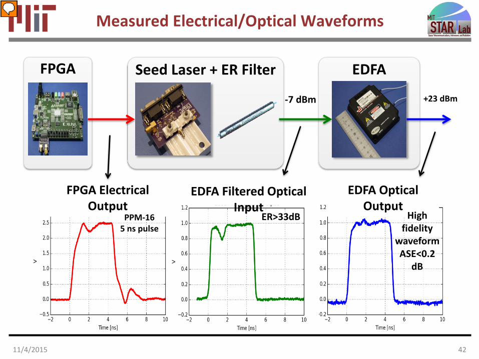
Measured Electrical/Optical Waveforms
Seed Laser + ER FilterFPGA EDFA
FPGA Electrical Output
EDFA Filtered Optical Input
EDFA Optical Output
PPM-165 ns pulse
+23 dBm
ER>33dB High fidelity
waveformASE<0.2
dB
-7 dBm
11/4/2015 42
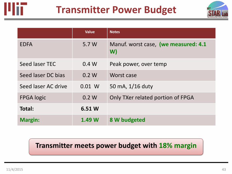
Transmitter Power Budget
Value Notes
EDFA 5.7 W Manuf. worst case, (we measured: 4.1 W)
Seed laser TEC 0.4 W Peak power, over temp
Seed laser DC bias 0.2 W Worst case
Seed laser AC drive 0.01 W 50 mA, 1/16 duty
FPGA logic 0.2 W Only TXer related portion of FPGA
Total: 6.51 W
Margin: 1.49 W 8 W budgeted
Transmitter meets power budget with 18% margin
11/4/2015 43

Flight Receiver BER Curves
System is currently 2.2– 3.0 dB from theory (mode dependent).
• Theoretical sensitivity from link budget
• Electrical noise at comparator is suspected limitations of eval-board prototype.
Sensitivity vs. Theory at BER=1e-4
M 8 16 32 64 128
dB 2.98
2.57
2.32
2.24
2.24
11/4/2015 44

Beacon Camera
11/4/2015 45
Lens + filters
Focal length 35 mm
Aperture 1”
Band-pass filter (850 5) nm
Long-pass filter > 700 nm
CMOS array - Aptina MT9P031
Optical format 1/2.5”
Resolution 2592H x 1944V
Pixel's pitch 2.2 μm
QE at 850 nm 15%
2.5 cm4 cm
9.4 cm
Camera with CMOS array
lensEFL = 35 mm filters
• CMOS focal plane array (5 Mpixels)• COTS camera lens system (1”, f = 35 mm)
• Bandpass filter – reject background light• UV/VIS-cut filter – reduce system heating
Beacon camera prototype COTS = Commercial Off the Shelf

Beacon Simulation
11/4/2015 46
centroid
region of interest
Link analysis
Transmit power 10 W
Wavelength 850 nm
Beamwidth 5 mrad
Range (20o elevation) 984 km
Atmospheric absorption/scattering -6 dB
Sky radiance5 180 W/m2/sr/um
Receiver bandwidth 10 nm
Optics loss (Tx + Rx) -8 dB
Received power 0.013 nW
Margin 10 dB
Simulated beacon image and centroid
Scintillation statistics
profile Huffnagel-Valley model31o/s slew speed
Scintillation index
Strong-turbulence model3Spatial diversity (4 beams)
Distribution Log-normal

Power (W)
Fade
pro
babi
lity
(%)
2.3 %
7.4%
16%
Beacon Simulation Results
11/4/2015 47
Fade probability Centroid accuracy
Attitude accuracy (urad)Pe
rcen
tage
(%)
mean = 30 μrad
Fade probability per frame (10 W) 2.3 %Attitude knowledge accuracy 30 μrad
(< 1/10 required accuracy)
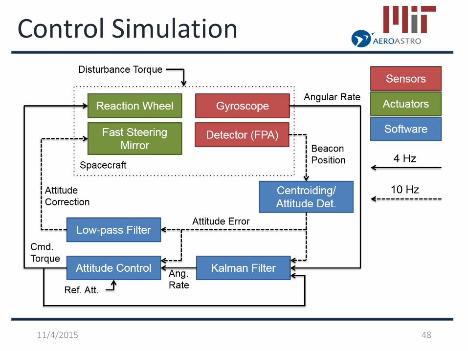
Control Simulation
11/4/2015 48
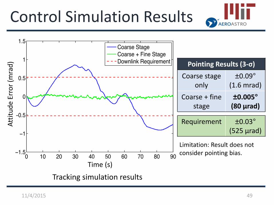
Control Simulation Results
Pointing Results (3-σ)Coarse stage
only±0.09°
(1.6 mrad)Coarse + fine
stage±0.005°
(80 μrad)
Requirement ±0.03°(525 μrad)
Limitation: Result does not consider pointing bias.
11/4/2015 49
Time (s)
Attit
ude
Erro
r (m
rad)
Tracking simulation results
NODE Future workNanosatellite Optical Downlink Experiment (NODE)• CubeSat-sized laser communication module• Pointing performance
• Attitude knowledge: 30 μrad (2.3% fading)• Tracking accuracy: 80 μrad
Future work• Hardware checkout and model validation• Camera readout and image processing implementation• Hardware-in-the-loop testing and integration• On-orbit calibration algorithm development
11/4/2015 50

NODE References1. E. Buchen and D. DePasquale, “2014 Nano / Microsatellite Market
Assessment,” Spaceworks Enterprises, Inc. (SEI), Atlanta, GA. 2014. 2. B. Klofas and K. Leveque, “A survey of cubesat communications systems:
2009-2012," in Proc. of CalPoly CubeSat Developers Workshop, 2013.
3. L. Andrews and R. Phillips “Laser Beam Propagation through Random Media, Second Edition” (SPIE Press Monograph Vol. PM152). SPIE – The International Society for Optical Engineering. ISBN-13: 978-0819459480
4. A. Schwarzenberg-Czerny, W. Weiss, A. Moat, R. Zee, and S. Rucinski, \The BRITE nano-satellite constellation mission," in Proc. of 38th COSPAR ScienticAssembly, 2010.
5. S. Lambert and W. Casey, Laser Communications in Space, Artech House Publishers, Boston, MA, 1995.
11/4/2015 51

Overview
• Introduction– CubeSats 101
• Communications– NODE
• Laser communication downlink
• Laser Occultation– Bending angle and T,P profile
recovery• GPS Radio Occutlation for
validation
NanoRacks deployment of MicroMAS from the ISS Japanese Experiment Module Remote Manipulator System (JEMRMS). Photo courtesy NASA/NanoRacks
5211/4/2015

Radio Occultation Illustration
Progression of tangent point for setting (ingress) occultation
53
Modified from L. Cucurull
11/4/2015
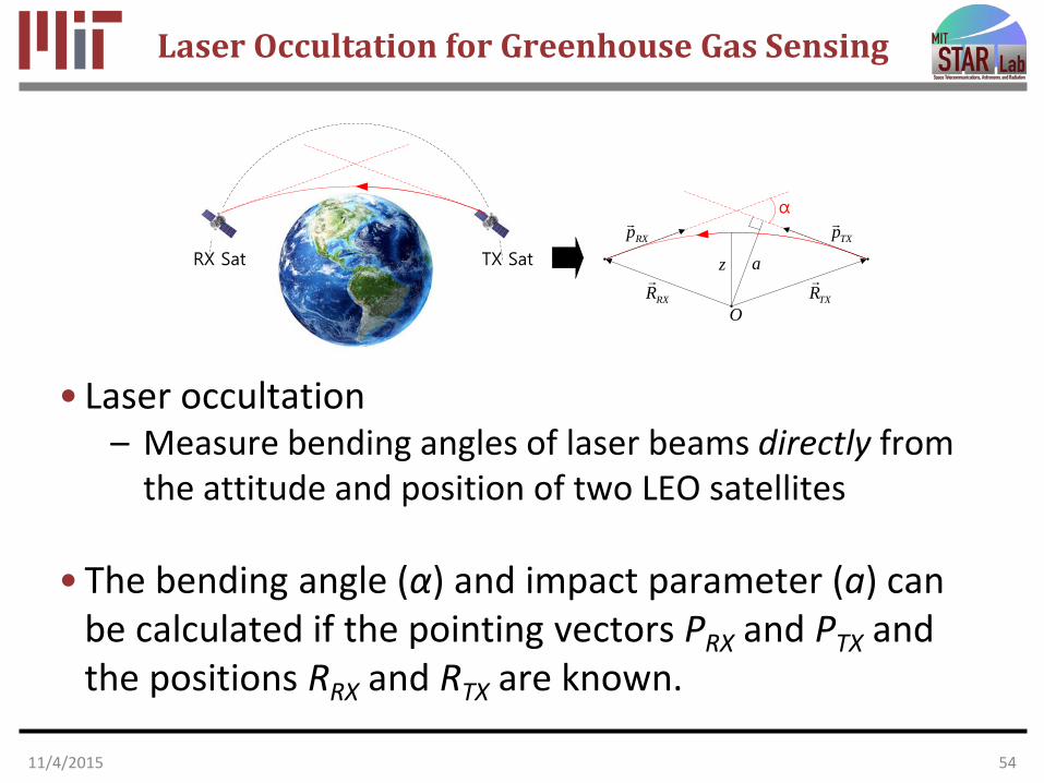
Laser Occultation for Greenhouse Gas Sensing
TX SatRX Sat
RXR
TXR
α
RXp TXp
z a
O
• Laser occultation– Measure bending angles of laser beams directly from
the attitude and position of two LEO satellites
• The bending angle (α) and impact parameter (a) can be calculated if the pointing vectors PRX and PTX and the positions RRX and RTX are known.
11/4/2015 54

Laser Occultation Angle Recovery
11/4/2015 55

Laser Occultation Schematic
11/4/2015 56

Laser Occultation 2um Wavelengths
11/4/2015 57
Species Wavenumber (cm^-1) Wavelength (nm)Abs H2O-1 4204.8403 2378.211605Ref H2O-1 4226.07 2366.264638Abs H2O-2 4475.803 2234.235957Ref H2O-2 4770.15 2096.370135
Abs H2O-3 4747.0548 2106.56932
shortest wavelength pair
Ref H2O-3 4731.03 2113.704627
shortest wavelength pair
Abs 12CO2 4771.6214 2095.723688
shortest wavelength pair
Ref 12CO2 4770.15 2096.370135
shortest wavelength pair
Abs 13CO2 4723.415 2117.112301Ref 13CO2 4731.03 2113.704627
Abs CH4 4344.1635 2301.939142Ref CH4 4322.93 2313.245877Abs O3 4029.1096 2481.937945Ref O3 4037.21 2476.958097
Abs N2O 4710.3408 2122.988638
shortest wavelength pair
Ref N2O 4731.03 2113.704627
shortest wavelength pair
From Kirchengast:http://wegcwww.uni-graz.at/publ/wegcpubl/arsclisys/2007/wegc_gkirchengastandsschweitzer-wegctechrepfffgalr-no3-2007.pdf
Need to assess 1.5-1.7 um wavelengths

Bending Angle
11/4/2015 58
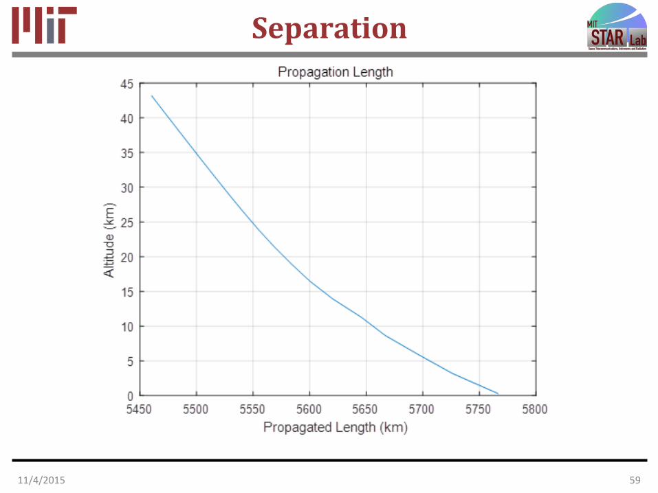
Separation
11/4/2015 59
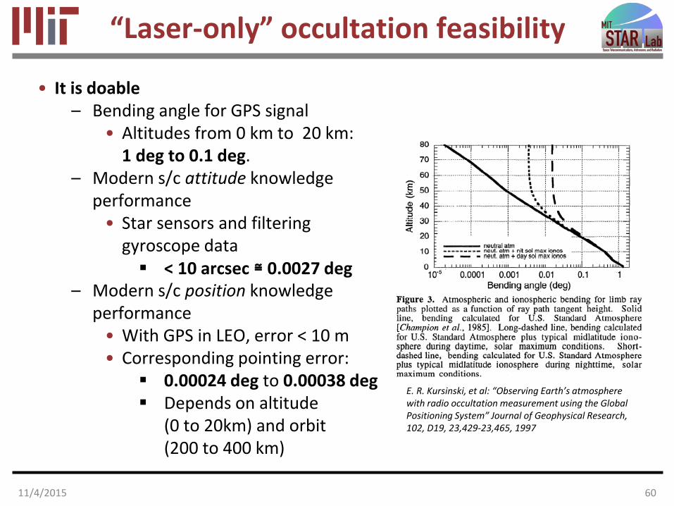
“Laser-only” occultation feasibility
• It is doable– Bending angle for GPS signal
• Altitudes from 0 km to 20 km: 1 deg to 0.1 deg.
– Modern s/c attitude knowledge performance
• Star sensors and filtering gyroscope data < 10 arcsec ≅ 0.0027 deg
– Modern s/c position knowledge performance
• With GPS in LEO, error < 10 m• Corresponding pointing error:
0.00024 deg to 0.00038 deg Depends on altitude
(0 to 20km) and orbit(200 to 400 km)
E. R. Kursinski, et al: “Observing Earth’s atmosphere with radio occultation measurement using the Global Positioning System” Journal of Geophysical Research, 102, D19, 23,429-23,465, 1997
11/4/2015 60

Thank you!
6111/4/2015
Recommended