Embed Size (px)
Citation preview

Leddar™ M16 Laser 16-Segment Solid-State LiDAR Sensor Module
USER GUIDE

2 | 101 © 2021 LeddarTech Inc.
This page intentionally left blank

54A0040-7.0EN / Leddar M16 Laser – User Guide 3 | 101
© 2021 LeddarTech Inc. All rights reserved.
The information contained herein is the property of the Company and shall not be reproduced in whole or in part without the prior written approval of the Company.
Leddar, LeddarTech, LeddarEngine, LeddarVision, LeddarSP, LeddarCore, VAYADrive, VayaVision, and related logos are trademarks or registered trademarks of LeddarTech Inc. All other brands, product names, and marks are or may be trademarks or registered trademarks used to identify products or services of their respective owners.
Please contact a LeddarTech sales representative if you have any questions regarding the information contained in this document or regarding LeddarTech products. For the most recent version of this document, visit LeddarTech’s website. We also highly recommend that you read our Standard Sales Terms and Conditions, Product Warranty, and End-User License Agreement carefully. Documentation available at www.leddartech.com, section “Resources”.
Leddar™ Configurator software: this software is based in part on the work of the Independent JPEG Group.
Keep this User Guide for future reference.

4 | 101 © 2021 LeddarTech Inc.
DISCLAIMER
LeddarTech® shall not be liable for any errors or omissions herein or for any damages arising out of or related to this document or the information contained herein, even if LeddarTech has been advised of the possibility of such damages.
Descriptions of products, including, but not limited to, specifications and drawings, and other related information contained in this document, are provided only to illustrate their operation and application examples. The illustrations shown, including screen captures, may differ from the appearance of the actual product.
LeddarTech has made every effort to ensure that the information contained in the documentation accompanying its products, including, without limitation, its Specification Sheet, is accurate. However, LeddarTech will not be liable for any errors or omissions therein and reserves the right to modify the design and characteristics of products at any time without notice. For the most recent version of any product documentation, visit LeddarTech’s website at www.leddartech.com. In case of discrepancy, the web version takes precedence over any printed literature.
LeddarTech may expressly designate certain products as completing a particular qualification (e.g., AEC-Q100). Customer agrees that it has the necessary expertise to select the product with the appropriate qualification designation for its applications and that proper product selection is at customer’s own risk. The customer is solely responsible for compliance with all legal and regulatory requirements in connection with such selection.
LeddarTech does not control the installation and use of its products and shall have no liability if a product is used for an application for which it is not suited. LeddarTech’s products are not recommended or authorized for safety, life support, medical applications, applications involving hazardous, corrosive, or radioactive substances, or for any use or application in which the failure of a component could cause personal injury, loss of life, or substantial harm to the environment or property. Where LeddarTech specifically promotes products as facilitating functional safety or as compliant with functional safety standards, such products are intended to help enable customers to design and create their own applications that meet applicable functional safety standards and requirements. Using products in an application does not by itself establish any safety features in the application.
Any technical advice provided by LeddarTech with reference to the use of its products is given without assumption by LeddarTech of any liability, and LeddarTech assumes no obligation or liability for the advice given or results obtained, all such advice being given and accepted at customer’s sole risk.
LeddarTech reserves the right to modify its products at any time, without notice, at its sole discretion. The products’ performance specifications and operating parameters are determined in an independent state and are not guaranteed to perform the same way if installed in a customer product.
54A0040-7.0EN / Leddar M16 Laser – User Guide 5 | 101
Table of Contents
INTRODUCTION ............................................................................................................................. 15
1.1. DESCRIPTION .................................................................................................................................. 15
1.2. UNDERLYING PRINCIPLES ................................................................................................................ 22
GETTING STARTED ....................................................................................................................... 23
2.1. SETUP ............................................................................................................................................ 23
2.2. CONNECTING TO THE MODULE ......................................................................................................... 26
MEASUREMENTS AND SETTINGS .............................................................................................. 28
3.1. DISTANCE MEASUREMENT ............................................................................................................... 28
3.2. DATA DESCRIPTION ......................................................................................................................... 28
3.3. ACQUISITION SETTINGS ................................................................................................................... 30
General Settings .................................................................................................................... 30
Enabling and Disabling Segments ........................................................................................ 35
Static Threshold..................................................................................................................... 37
3.4. MEASUREMENT RATE ...................................................................................................................... 37
3.5. CPU LOAD ..................................................................................................................................... 39
3.6. SERIAL PORT SETTINGS .................................................................................................................. 39
3.7. CAN PORT SETTINGS ..................................................................................................................... 41
COMMUNICATION.......................................................................................................................... 43
4.1. SERIAL PORT .................................................................................................................................. 43
4.2. CAN BUS ....................................................................................................................................... 49
LEDDAR CONFIGURATOR ........................................................................................................... 57
5.1. INTRODUCTION................................................................................................................................ 57
5.2. CONNECTION WINDOW .................................................................................................................... 57
5.3. LEDDAR CONFIGURATOR MAIN WINDOW .......................................................................................... 58
Toolbar Display Controls ....................................................................................................... 59
Fit to Window ......................................................................................................................... 59
Force Equal Horizontal and Vertical Scales .......................................................................... 59
Zoom In ................................................................................................................................. 59
Zoom Out ............................................................................................................................... 59
Scale ...................................................................................................................................... 59
Panning and Zooming ........................................................................................................... 59
Changing the Module Origin .................................................................................................. 61
Changing the Module Orientation.......................................................................................... 62
5.4. SETTINGS ....................................................................................................................................... 63
Device Name ......................................................................................................................... 63

6 | 101 © 2021 LeddarTech Inc.
Acquisition Settings ............................................................................................................... 64
Module Position ..................................................................................................................... 64
Advanced Detection Zones ................................................................................................... 65
General .................................................................................................................................. 65
Serial Ports ............................................................................................................................ 66
CAN Ports .............................................................................................................................. 68
5.5. SAVING AND LOADING A CONFIGURATION ......................................................................................... 70
5.6. CONFIGURING DETECTION RECORDS ............................................................................................... 70
5.7. USING DETECTION RECORDS .......................................................................................................... 72
5.8. DATA LOGGING ............................................................................................................................... 73
5.9. DEVICE STATE ................................................................................................................................ 75
5.10. PREFERENCES ................................................................................................................................ 76
5.11. RAW DETECTIONS ........................................................................................................................... 77
5.12. VIEW SERIAL PORT DATA ................................................................................................................ 79
SPECIFICATIONS ........................................................................................................................... 82
6.1. GENERAL........................................................................................................................................ 82
6.2. ENVIRONMENTAL............................................................................................................................. 82
6.3. REGULATORY COMPLIANCE ............................................................................................................. 82
6.4. OPTICAL ......................................................................................................................................... 83
6.5. PERFORMANCE ............................................................................................................................... 84
6.6. DIMENSIONS ................................................................................................................................... 85
36° x 0.2° Module (M16R-75J0002) ...................................................................................... 85
19° x 0.3° Module (M16R-75J0012) ...................................................................................... 86
19° x 3° Module (M16R-75J0003) ......................................................................................... 87
48° x 0.3° Module (M16R-75J0007) ...................................................................................... 88
48° x 3° Module (M16R-75J0008) ......................................................................................... 89
48° x 5.1° Module (M16R-75J0001) ...................................................................................... 90
48° x 5.5° Module (M16R-75J0011-1) ................................................................................... 91
99° x 0.3° Module (M16R-75J0009) ...................................................................................... 92
99° x 3° Module (M16R-75J0010) ......................................................................................... 93
TROUBLESHOOTING .................................................................................................................... 94
MAINTENANCE .............................................................................................................................. 94
DISPOSAL ....................................................................................................................................... 94
TECHNICAL SUPPORT .................................................................................................................. 94
APPENDIX A. EXAMPLE OF A 0X41 MODBUS FUNCTION .............................................................. 95
APPENDIX B. EXAMPLE OF A 0X04 MODBUS .................................................................................. 97
APPENDIX C. EXAMPLE OF A CAN BUS DETECTION REQUEST .................................................. 99

54A0040-7.0EN / Leddar M16 Laser – User Guide 7 | 101
Table of Figures
Fig. 1: Perspective front view ........................................................................................................................ 16
Fig. 2: Top view with terminal block connector ............................................................................................. 16
Fig. 3: Perspective back view........................................................................................................................ 17
Fig. 4: M16 LSR working diagram ................................................................................................................. 19
Fig. 5: Expansion connector.......................................................................................................................... 20
Fig. 6: Illumination area and detection zone ................................................................................................. 22
Fig. 7: Welcome dialog box ........................................................................................................................... 23
Fig. 8: End-User License Agreement dialog box .......................................................................................... 24
Fig. 9: Product Types dialog box .................................................................................................................. 24
Fig. 10: Destination Folder dialog box .......................................................................................................... 25
Fig. 11: Installing ........................................................................................................................................... 25
Fig. 12: Completing the installation ............................................................................................................... 25
Fig. 13: Connecting to a module ................................................................................................................... 26
Fig. 14: Connection dialog box...................................................................................................................... 26
Fig. 15: Main window .................................................................................................................................... 27
Fig. 16: Distance measurement .................................................................................................................... 28
Fig. 17: Raw Detections dialog box .............................................................................................................. 28
Fig. 18: General tab – Acquisition Settings dialog box ................................................................................. 30
Fig. 19: Detection thresholds ........................................................................................................................ 33
Fig. 20: Measurement smoothing example ................................................................................................... 35
Fig. 21: Segments tab – Acquisition Settings dialog box .............................................................................. 35
Fig. 22: Disabled segments example ............................................................................................................ 36
Fig. 23: Static Threshold tab – Acquisition Settings dialog box .................................................................... 37
Fig. 24: Device State window ........................................................................................................................ 39
Fig. 25: Raw Detections dialog box docked on the side of the main window ............................................... 57
Fig. 26: Connection dialog box...................................................................................................................... 57
Fig. 27: Leddar Configurator main window ................................................................................................... 58
Fig. 28: Zooming in (left) and out (right) horizontally .................................................................................... 60
Fig. 29: Zooming in (left) and out (right) vertically......................................................................................... 60
Fig. 30: Detection point coordinates ............................................................................................................. 61
Fig. 31: Dot indicator to modify the module origin ........................................................................................ 61
Fig. 32: Module position display .................................................................................................................... 62
Fig. 33: Red bar to rotate the module position .............................................................................................. 62

8 | 101 © 2021 LeddarTech Inc.
Fig. 34: Device menu – Configuration menu items ....................................................................................... 63
Fig. 35: Device Name dialog box .................................................................................................................. 63
Fig. 36: Acquisition Settings dialog boxes .................................................................................................... 64
Fig. 37: Device menu – Sensor Position dialog box ..................................................................................... 64
Fig. 38: Device menu – Configuration and Advanced Detection Zones menu items ................................... 65
Fig. 39: Advanced Detection Zones dialog box ............................................................................................ 65
Fig. 40: Device menu – Configuration and Communication menu items ...................................................... 66
Fig. 41: General Settings dialog box ............................................................................................................. 66
Fig. 42: LeddarHost dialog box ..................................................................................................................... 66
Fig. 43: Device menu – Configuration and Communication menu items ...................................................... 67
Fig. 44: Serial Ports Settings dialog box ....................................................................................................... 67
Fig. 45: Device menu – Configuration and Communication menu items ...................................................... 68
Fig. 46: CAN Port Settings dialog box .......................................................................................................... 69
Fig. 47: File menu ......................................................................................................................................... 70
Fig. 48: Settings menu .................................................................................................................................. 70
Fig. 49: Preferences dialog box .................................................................................................................... 71
Fig. 50: File menu ......................................................................................................................................... 71
Fig. 51: File menu to stop a recording .......................................................................................................... 72
Fig. 52: File menu to open a recording ......................................................................................................... 73
Fig. 53: Record Replay dialog box ................................................................................................................ 73
Fig. 54: Settings menu .................................................................................................................................. 74
Fig. 55: Preferences dialog box for logging data .......................................................................................... 74
Fig. 56: File menu ......................................................................................................................................... 74
Fig. 57: File menu to stop data recording ..................................................................................................... 75
Fig. 58: View menu ....................................................................................................................................... 75
Fig. 59: Device State window ........................................................................................................................ 75
Fig. 60: Settings Menu – Preferences dialog box ......................................................................................... 76
Fig. 61: View menu – Raw Detections dialog box ........................................................................................ 77
Fig. 62: Example of detection filtering in the Raw Detections dialog box ..................................................... 78
Fig. 63: View menu – Preferences dialog box .............................................................................................. 80
Fig. 64: Serial Port Viewer dialog box ........................................................................................................... 80
Fig. 65: Serial port measurement .................................................................................................................. 81
Fig. 66: Horizontal field of view (HFoV) and vertical field of view (VFoV) .................................................... 83
Fig. 67: 36° x 0.2° module dimensions ......................................................................................................... 85
Fig. 68: 19° x 0.3° module dimensions ......................................................................................................... 86
Fig. 69: 19° x 3° module dimensions ............................................................................................................ 87
Fig. 70: 48° x 0.3° module dimensions ......................................................................................................... 88

54A0040-7.0EN / Leddar M16 Laser – User Guide 9 | 101
Fig. 71: 48° x 3° module dimensions ............................................................................................................ 89
Fig. 72: 48° x 5.1° module dimensions ......................................................................................................... 90
Fig. 73: 48° x 5.5° module dimensions ......................................................................................................... 91
Fig. 74: 99° x 0.3° module dimensions ......................................................................................................... 92
Fig. 75: 99° x 3° module dimensions ............................................................................................................ 93

10 | 101 © 2021 LeddarTech Inc.
List of Tables
Table 1: Terminal block connector pin definition........................................................................................... 17
Table 2: RS-485 pin definition ....................................................................................................................... 20
Table 3: Expansion connector pin definition ................................................................................................. 20
Table 4: UART pin definition (TTL 3.3 V) ...................................................................................................... 21
Table 5: CAN pin definition ........................................................................................................................... 21
Table 6: SPI pin definition ............................................................................................................................. 21
Table 7: Distances per segment (channel) ................................................................................................... 22
Table 8: Raw Detection field description ....................................................................................................... 29
Table 9: Flag value description ..................................................................................................................... 29
Table 10: Status value description ................................................................................................................ 29
Table 11: Acquisition settings description ..................................................................................................... 30
Table 12: Base rate ....................................................................................................................................... 37
Table 13: Theoretical measurement rate ...................................................................................................... 38
Table 14: Serial port settings description ...................................................................................................... 39
Table 15: Maximum detections per baud rate / Measurement rate settings ................................................. 40
Table 16: CAN port settings .......................................................................................................................... 41
Table 17: Report server ID message ............................................................................................................ 43
Table 18: Get detection message (detection fields) ..................................................................................... 44
Table 19: Get detection message (trailing fields).......................................................................................... 44
Table 20: Get detection message (detection fields) ..................................................................................... 45
Table 21: Get detection message (trailing fields).......................................................................................... 45
Table 22: Read input register message ........................................................................................................ 45
Table 23: Read holding register message definition ..................................................................................... 47
Table 24: CAN bus request message ........................................................................................................... 49
Table 25: CAN bus request message (GET input data) ............................................................................... 50
Table 26: CAN bus request message (GET holding data) ........................................................................... 50
Table 27: CAN bus request message (SET holding data) ............................................................................ 51
Table 28: CAN bus answer message ........................................................................................................... 53
Table 29: CAN bus number of detection message ....................................................................................... 54
Table 30: CAN bus answer message (GET input data) ................................................................................ 54
Table 31: Standard CAN bus detection message ......................................................................................... 56
Table 32: Flag information of measurement ................................................................................................. 56
Table 33: CAN bus detection message definition with flag information ........................................................ 56
Table 34: Serial port settings description ...................................................................................................... 67
Table 35: CAN port settings description ....................................................................................................... 69

54A0040-7.0EN / Leddar M16 Laser – User Guide 11 | 101
Table 36: Field description of the log text file................................................................................................ 73
Table 37: Flag value description ................................................................................................................... 79
Table 38: Status value description ................................................................................................................ 79
Table 39: General specifications ................................................................................................................... 82
Table 40: Environmental specifications ........................................................................................................ 82
Table 41: Optical specifications .................................................................................................................... 83
Table 42: Module performances ................................................................................................................... 84

12 | 101 © 2021 LeddarTech Inc.
Version History
Version Description Date (YYYY-MM-DD)
54A0040-6.0EN
• Updated to new User Guide template with minor corrections throughout the text, including for consistency
• Updated Disclaimer information
• Added Version History information (this table)
• Section 1.1: added Fig. 5 and specified expansion connector type
• Section 5.4.4: described Rise and Fall Debouncing parameters
• Sections 7, 8, 9: added Troubleshooting, Maintenance, and Disposal information
2021-02-26
54A0040-7.0EN
• Section 3.3.1: added footnote 2 in Table 11
• Section 3.4: added paragraph on processing time above Table 13 and renamed the table “Theoretical measurement rate”
• Section 6.5: added footnote 14 in Table 42
2021-03-23

54A0040-7.0EN / Leddar M16 Laser – User Guide 13 | 101
Contact Information
LeddarTech Inc.
Address
Head Office Production & Shipping
4535, boulevard Wilfrid-Hamel, Suite 240
Québec (Québec) G1P 2J7, Canada
4535, boulevard Wilfrid-Hamel, Suite 140
Québec (Québec) G1P 2J7, Canada
Phone
+ 1-418-653-9000
+ 1-855-865-9900
8:30 a.m. – 5:00 p.m. EST
Fax + 1-418-653-9099
Support [email protected]
Website www.leddartech.com

14 | 101 © 2021 LeddarTech Inc.
Document Conventions
This document uses the following conventions:
Name of menu > name of window
Shows the access path to menus under each section of Leddar™ Configurator.
Arial bold The names of buttons, menus, dialog boxes, and elements of the interface are in bold type.
Note: Contains helpful suggestions and references to information included within this User Guide.
Warning: Refers to a warning or important information to follow.
This document uses the metric system (SI).

54A0040-7.0EN / Leddar M16 Laser – User Guide 15 | 101
Introduction
The Leddar™ M16 module or M16 LSR (Laser) enables developers and integrators to make the most of Leddar™ technology through integration in detection and ranging systems. The purpose of the M16 LSR module is to be easily and rapidly integrated in various applications.
The M16 LSR can be configured to be used in very simple applications or to perform more complex tasks depending on the hardware and software settings.
1.1. Description
The M16 LSR contains the following:
• Receiver assembly
• Source and control assembly
The M16 LSR offers the following features:
• Horizontal field of view (FoV): 19°, 36°, 48°, and 99°
• 16 detection segments
• Real-time data acquisition and display (through USB)
• RS-485 port for measurement acquisition
• CAN bus for measurement acquisition
Interfaces available for custom application development:
• RS-485
• CAN bus
• DIP switches1 (4 x)
• MicroSD card slot1
• Expansion connector (UART, CAN, SPI1, GPIO1, DAC1)
1 Not implemented in the current MCU firmware.

16 | 101 © 2021 LeddarTech Inc.
Fig. 1: Perspective front view
Fig. 2: Top view with terminal block connector
Reset button
MCU JTAG
USB port
Terminal block connector
Power connector
Emission optics
Reception optics
Pin 1 Pin 8
54A0040-7.0EN / Leddar M16 Laser – User Guide 17 | 101
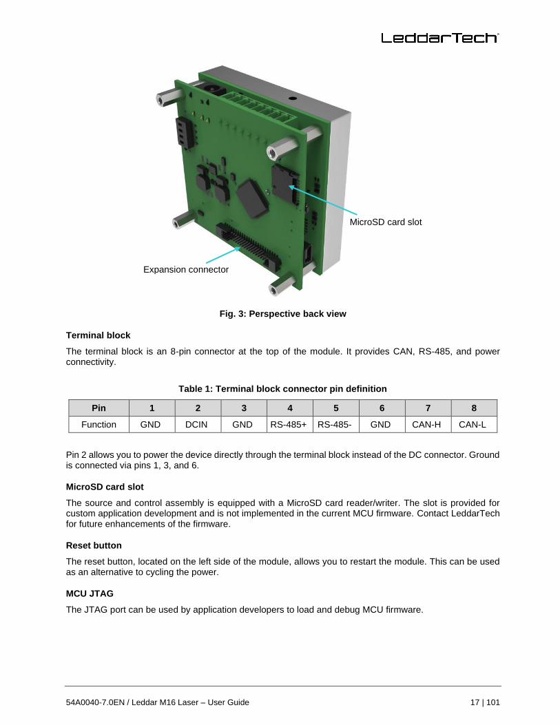
Fig. 3: Perspective back view
Terminal block
The terminal block is an 8-pin connector at the top of the module. It provides CAN, RS-485, and power connectivity.
Table 1: Terminal block connector pin definition
Pin 1 2 3 4 5 6 7 8
Function GND DCIN GND RS-485+ RS-485- GND CAN-H CAN-L
Pin 2 allows you to power the device directly through the terminal block instead of the DC connector. Ground is connected via pins 1, 3, and 6.
MicroSD card slot
The source and control assembly is equipped with a MicroSD card reader/writer. The slot is provided for custom application development and is not implemented in the current MCU firmware. Contact LeddarTech for future enhancements of the firmware.
Reset button
The reset button, located on the left side of the module, allows you to restart the module. This can be used as an alternative to cycling the power.
MCU JTAG
The JTAG port can be used by application developers to load and debug MCU firmware.
MicroSD card slot
Expansion connector

18 | 101 © 2021 LeddarTech Inc.
USB port
The USB port is a standard 2.0, 12-MBit/s port. This communication link is used by the Leddar Configurator software and provides a link for prototyping new applications (contact LeddarTech for the SDK).
Power connector
The power connector provides the module with a power source from 10 V to 30 V.
Receiver assembly
The receiver assembly contains the photodetector array (16 elements) and the controller for laser pulsing and data acquisition. Data acquisition is performed at a sampling frequency of 62.5 MHz.
The module assembly generates a full waveform per segment at the module measurement rate.
The module measurement rate varies according to the oversampling, accumulation settings, and the pulse rate according to FoV configuration.
Lens coating color for 48° configuration may change from one sample to another from greenish to bluish, but the inherent properties of the lens are not affected in the field of application of this product.
Source and control assembly
The laser pulsing is controlled by the receiver assembly since the receiver data acquisition must be synchronized with the laser pulses. A temperature module located near the laser is used to implement temperature compensation on the ranging results.
The MCU recovers the waveforms generated by the receiver assembly, performs full waveform analysis, and generates detection and ranging data. The data can be displayed in software after a connection has been established through the USB link.
The control assembly offers several external interfaces, but most are provided for custom application development and are not implemented in the current MCU firmware. Contact LeddarTech for future enhancements of the firmware.
The following diagram illustrates how the components of the module interact with one another.

54A0040-7.0EN / Leddar M16 Laser – User Guide 19 | 101
Fig. 4: M16 LSR working diagram
The receiver assembly includes the reception optics and the photodetector circuit.
The control assembly includes the terminal block, the MCU, and the external interfaces.
The source assembly includes the laser, the laser drivers, and emission optics.
DIP switches
The source and control assembly is equipped with four DIP switches. They are unused by the current design and are thus available as additional options for the development of custom applications.
RS-485 port
The RS-485 (ANSI/TIA/IEA-485) is a two-wire, half-duplex differential serial communication port. It is often used in electrically noisy environments. The following table provides the pin definitions compliant to RS-485 standards.

20 | 101 © 2021 LeddarTech Inc.
Table 2: RS-485 pin definition
Pin 4 B Non-inverting +DATA
Pin 5 A Inverting -DATA
CAN bus
The CAN bus is implemented via a differential pair. Pin 7 connects to CAN-High (CAN+) and pin 8 to CAN-Low (CAN-). The ISO 11898 standard describes the CAN technology.
Expansion connector
The expansion connector is another connectivity option that can be used for custom application development.
The UART link is the only option implemented in the current MCU firmware.
Fig. 5: Expansion connector
Connector type: Samtec® FTS-120-02-F-DV-SA-P-TR, 50 mil pitch
Recommended mating connector type: Samtec® CLP-120-02-F-D-A
Even numbered pins connect to the ground and odd-numbered pins are described below.
Table 3: Expansion connector pin definition
UART CAN GPIO/SPI/... DAC +3.3 V +5.4 V DC
Pin 1 3 5 7 9 11 13 15 17 19 21 23 25 27 29 31 33 35 37 39
2 4 6 8 10 12 14 16 18 20 22 24 26 28 30 32 34 36 38 40 GND
• UART
Pins 1, 3, 5, and 7 connect to UART2 from the MCU.
Pin 1 (upper row)
Pin 40 (lower row)

54A0040-7.0EN / Leddar M16 Laser – User Guide 21 | 101
Table 4: UART pin definition (TTL 3.3 V)
Pin Function
1 TX
3 RX
5 CTS
7 RTS
• CAN
Another CAN bus connector is available. Unlike the one on the terminal block, you are responsible for converting the receiver/transmitter signals to the CAN standard (CAN-High and CAN-Low).
Table 5: CAN pin definition
Pin Function
9 TX
11 RX
• GPIO
General-purpose inputs/outputs are available through pins 13, 15, 17, 19, 21, 23, 25, and 27.
• SPI
The generic serial port interface functionality is available through pins 19, 21, 23, and 25.
Table 6: SPI pin definition
Pin Function
19 MOSI
21 MISO
23 SCLK
25 CS
• DAC
Pin 29 is a digital-to-analog output. The reference voltage is 3.3 V.
Status LEDs
There are two LEDs on this unit. One shows the activity of the microcontroller (D6 blinking LED), and the other shows the USB connection status (D5 LED).

22 | 101 © 2021 LeddarTech Inc.
1.2. Underlying Principles
Created by LeddarTech, Leddar™ (light-emitting diode detection and ranging) is a unique sensing technology based on laser illumination (infrared spectrum) and the time-of-flight of light principle. The laser emitters illuminate the area of interest (pulsed typically at 100 kHz), and the multichannel module receiver collects the backscatter of the emitted light and measures the time taken for the emitted light to return to the module.
A 16-segment photodetector array is used and provides multiple detection and ranging segments. The full-waveform analysis enables detection and distance measurement of multiple objects in each segment, provided foreground objects do not fully obscure objects behind them.
Fig. 6 illustrates the illumination area and detection segments. The 16 segments provide a profile of the object in the beam. In other installations, the 16 segments can locate and track one or multiple objects in the beam.
Table 7: Distances per segment (channel)
Segment 1 2 3 4 5 6 7 8 9 10 11 12 13 14 15 16
Distance (m) 9.71 8.52 7.55 6.79 6.18 5.68 5.26 4.91 4.61 4.82 5.18 5.62 6.18 6.88 7.80 8.97
Fig. 6: Illumination area and detection zone
The core of Leddar sensing is the pulsing of diffused light, collection of reflected light, and full-waveform analysis (including oversampling and accumulation). The light source type, the number of light sources, and the illumination and reception beam can all be tailored to fit specific application requirements such as detection range, beam, and spatial resolution.

54A0040-7.0EN / Leddar M16 Laser – User Guide 23 | 101
Getting Started
This chapter presents the steps to install Leddar™ Configurator and start using the M16 LSR.
2.1. Setup
This section explains the Leddar™ Configurator installation and the procedure to set up the M16 LSR. All software operations are described in section “5. Leddar Configurator”.
To install Leddar Configurator:
Download the LeddarInstaller.exe file from our website at: www.leddartech.com/resources/#product-download/.
In the Product Download section, select LeddarConfigurator Software then click LeddarInstaller.exe. Double-click the file to start the installation.
For Microsoft Windows® XP, an upgrade of Microsoft components and a restart may be required. Installation will automatically resume after restarting the computer.
1. On the computer desktop, double-click the Leddar™ Configurator icon.
2. In the Welcome to the Leddar™ Software 3 Setup Wizard dialog box, click Next.
Fig. 7: Welcome dialog box
3. In the End-User License Agreement dialog box, read the terms of the agreement, select the I accept the terms in the License Agreement check box, and click Next.
24 | 101 © 2021 LeddarTech Inc.
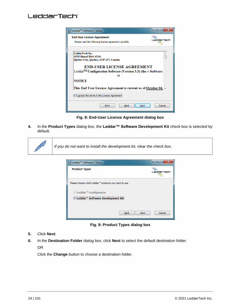
Fig. 8: End-User License Agreement dialog box
4. In the Product Types dialog box, the Leddar™ Software Development Kit check box is selected by default.
If you do not want to install the development kit, clear the check box.
Fig. 9: Product Types dialog box
5. Click Next.
6. In the Destination Folder dialog box, click Next to select the default destination folder.
OR
Click the Change button to choose a destination folder.

54A0040-7.0EN / Leddar M16 Laser – User Guide 25 | 101
Fig. 10: Destination Folder dialog box
7. In the Ready to Install Leddar™ Software 3 dialog box, click the Install button.
Fig. 11: Installing
8. In the Completed the Leddar™ Software 3 Setup Wizard dialog box, click Finish.
Fig. 12: Completing the installation
Leddar Configurator creates an icon on the computer desktop.

26 | 101 © 2021 LeddarTech Inc.
2.2. Connecting to the Module
The first time the module is connected to a computer, a few seconds are required for Windows™ to detect it and complete the installation.
Once the installation is completed, you can connect to the module.
To connect to the module:
1. Connect the power cord to the module and to a power outlet.
2. Connect the USB cable to the module and to the computer.
3. On the computer desktop, double-click the Leddar™ Configurator icon.
4. In Leddar™ Configurator, click the Connect button.
Fig. 13: Connecting to a module
5. In the Select a connection type list of the Connection dialog box, select the IS16/M16/Evaluation Kit USB option.
Fig. 14: Connection dialog box
6. In the product list, select the product and click the Connect button.

54A0040-7.0EN / Leddar M16 Laser – User Guide 27 | 101
The main window displays the detections (green lines) in the segments (white lines).
Fig. 15: Main window
A complete description of Leddar Configurator features and parameters for the M16 LSR can be found in section “5. Leddar Configurator”.

28 | 101 © 2021 LeddarTech Inc.
Measurements and Settings
This chapter presents measurements, settings, and zone definition for the M16 LSR.
3.1. Distance Measurement
Distance is measured from the base of the standoffs for the M16 LSR.
Fig. 16: Distance measurement
The dashed lines illustrate 1 of the 16 segments and the solid line indicates the distance measured by the module in that segment.
3.2. Data Description
Data displayed in the Raw Detections dialog box allow you to precisely define the desired detection parameters (View menu > Raw Detections).
Fig. 17: Raw Detections dialog box

54A0040-7.0EN / Leddar M16 Laser – User Guide 29 | 101
An object crossing the beam of the module is detected and measured. It is qualified by its distance, segment position, and amplitude. The quantity of light reflected to the module by the object generates the amplitude. The bigger the reflection, the higher the amplitude will be.
The amplitude is expressed in counts. A count is the unit value of the used ADC in the receiver. The fractional of counts is caused by the accumulation to achieve more precision.
Table 8: Raw Detection field description
Field Description
Segment (Seg) Beam segment in which the object is detected
Distance Position of the detected object
Amplitude Quantity of light reflected by the object and measured by the module
Flags 8-bit status (bit field). See Table 9.
The Flag parameter provides the status information that indicates the measurement type.
Table 9: Flag value description
Bit Position Bit = 0 Bit = 1
0 Invalid measurement Valid measurement
1 Normal measurement Measurement is the result of demerging processing.
2 Normal measurement Interference was detected in the current frame.
3 Normal measurement
Received signal is above the saturation level.
Measurements are valid (VALID is set) but have lower accuracy and precision.
Consider decreasing the laser intensity value.
4 Reserved Reserved
5 Reserved Reserved
6 Normal measurement Detection is within the crosstalk zone.
7 Reserved Reserved
The Flag field provisions for 8 bits encoded as a bit field. Three bits are currently used. The following table lists the implemented decimal values of the status bit field.
Table 10: Status value description
Status Value (Decimal) Status Value (Binary) Description
1 00000001 Normal measurement (valid)
9 00001001 Saturated signal (valid)

30 | 101 © 2021 LeddarTech Inc.
3.3. Acquisition Settings
Acquisition settings allow you to define parameters to use for detection.
To open the Acquisition Settings dialog box, select Device > Configuration > Acquisition.
General Settings
Fig. 18: General tab – Acquisition Settings dialog box
To apply new acquisition settings, click the Apply button in the main window.
Table 11: Acquisition settings description
Parameter Description Range
Accumulations
Number of accumulations
Higher values enhance range and reduce measurement rate and noise.
1
2
4
8
16
32
64
128
256
512
1 024

54A0040-7.0EN / Leddar M16 Laser – User Guide 31 | 101
Parameter Description Range
Oversampling2
Number of oversampling cycles
Higher values enhance accuracy/range and reduce the measurement rate.
1
2
4
8
Point Count Number of base sample points
Allows you to set the maximum detection range. 2 to 64
Approximate Range
Set the Point Count value using the up and down arrows to view the approximate range in meters or feet.
Varies
Refresh Rate
The theoretical measurement rate indicated in Hz
The real measurement rate is shown in the Device State window under View > State.
Refer to section “3.4 Measurement Rate” on page 37 for more details.
Varies
Threshold Offset Modification to the amplitude threshold
Higher values decrease sensitivity and reduce range.
−5 to 100.00
Smoothing
Object smoothing algorithm
Used to smooth the module measurements.
The behavior of the smoothing algorithm can be adjusted by a value ranging from −16 to 16. Higher values enhance the module precision but reduce the module reactivity.
The smoothing algorithm can be deactivated by selecting the Disabled check box or by entering −17 in the Smoothing field.
The measurement smoothing algorithm is advised for applications that need to measure slowly moving objects with high precision.
For applications requiring to quickly track moving objects, the smoothing should be configured with a value lower than 0 or simply deactivated.
−16 to 16
Disabled at −17
LED Control (Laser Intensity)
Laser power control options
Allow you to select between manual and automatic power control. In automatic mode, the laser power is adjusted according to incoming detection amplitudes.
The current laser power level is visible in the View > State > Device State window.
100%
90%
80%
65%
50%
35%
20%
10%
Change Delay
Minimum frame delay between power changes
Smaller numbers speed up the response time of the laser power adjustment.
Varies
Object Demerging
Near-object discrimination
Allows you to ease the discrimination of multiple objects in the same segment.
Object demerging is only available for a minimum of 8 oversampling and a minimum of 256 accumulations. The number of merged pulses
N/A
2 Oversampling of 1 and 2 might lead to accuracy below specification.

32 | 101 © 2021 LeddarTech Inc.
Parameter Description Range
that can be processed for each frame is also limited. A status field is available in the device states window (Leddar Configurator), indicating if the module processes all merged pulses.
The measurement precision of demerged objects tends to be of less quality than on usual detections.
Crosstalk Removal
Inter-channel interference noise mitigation
Crosstalk is a phenomenon inherent to all multiple segments time-of-flight modules. It causes a degradation of the distance measurement accuracy of an object when one or more objects with significantly higher reflectivity are detected in other segments at a similar distance.
This option enables an algorithm to compensate for the degradation due to crosstalk.
This algorithm increases the computational load of the module microcontroller. It is recommended to disable the Crosstalk Removal option if the module is configured to run at a rate higher than 50 Hz.
N/A
Static Threshold Default amplitude value (based on distance) under which detections are discarded to mitigate noise. It can be deactivated to gain more sensitivity.
Enabled
Disabled
Interference When enabled, this setting allows you to compare the previous and current frames to detect false positive detections and discard them.
Enabled
Disabled
Threshold Offset
The threshold offset is a value that allows you to modify the detection amplitude threshold.
A default detection threshold table was determined to provide robust detection and minimize false detections caused by noise in the input signal.
Fig. 19 presents the threshold table for a LED Intensity of 16. This table is effective when the threshold offset value is 0.

54A0040-7.0EN / Leddar M16 Laser – User Guide 33 | 101
Fig. 19: Detection thresholds
The multiple lines on each graph present the thresholds for a few accumulations of 1 (top curve), 2, 4, 8, 16, 32, 64, 128, and 256 (bottom curve). Accumulations of 512 and 1024 are also available, although not shown (provide the lowest thresholds).
The threshold offset parameter has the effect of offsetting each value in the threshold table by the selected value. This provides a means of reducing the sensitivity (positive value) or increasing the sensitivity (negative value) of the module. Increasing the value of the threshold offset allows ignoring (will not result in a measurement) signals with an amplitude higher than the default threshold. Decreasing the value of the threshold offset allows measurements of amplitude signals lower than the default threshold.
The default setting (0) is selected to ensure a very low occurrence of false measurements.
False measurements are likely to occur when reducing the threshold offset (negative values). These false measurements are very random in occurrence while true measurements are repeatable. For this reason, it may be useful in some applications to use a higher sensitivity and filter out the false measurements at the application level. For example, this can be useful in applications that require long detection ranges or detection of small or low reflectivity targets.
Laser Intensity
There are a total of 8 supported laser power levels. Their approximate relative power is as follows: 10%, 20%, 35%, 50%, 65%, 80%, 90%, and 100%.

34 | 101 © 2021 LeddarTech Inc.
There are three power control modes:
• Manual
• Automatic mode 1
• Automatic mode 2
With the manual mode, the light power source of the module is set to a fixed value. This mode can be used in a controlled environment of module FoV.
For automatic mode, the change delay allows you to define the number of measurements required before allowing the module to increase or decrease the light source power level by one. For example, with the same change delay, the maximum rate of changes (per second) of the light source power will be twice higher at 12.5 Hz than at 6.25 Hz. The change delay can be set by the number of detection frames and the number of saturated segments that can be tolerated (automatic mode 1 only).
The change delay allows you to define the number of measurements required before allowing the module to increase or decrease the laser power level by one. For example, with the same change delay, the maximum rate of changes (per second) of the laser power will be twice higher at 12.5 Hz than at 6.25 Hz.
Since the change delay parameter is a number of measurements, the delay will vary if the measurement rate is changed (through modification of the accumulation and oversampling parameters).
Keeping the module in automatic laser power mode (default setting) ensures it adapts to varying environments. Close range objects may reflect so much light that they can saturate the module, reducing the quality of the measurements. This mode will adapt the light output within the change delay setting to reach the optimal amplitude. On the other hand, low amplitudes provide lower accuracy and precision. The automatic laser power mode will select a laser intensity that provides the highest intensity to avoid the saturation condition.
This automatic light source power mode will select a light source intensity that provides the highest intensity that avoids the saturation condition. Automatic mode 2 will adapt the light output within the change delay (frame parameter only) to reach at least one or more segments in saturation condition to provide the highest detection range. This mode is useful to keep a highest detection range into non-saturated segments when a strongly reflective object is detected.
When a strongly reflective or nearby object is present in the field of view while monitoring farther distances, the automatic adjustment will reduce the effective range of the module (reduced laser intensity value) and may prevent detection of long-range or low reflectivity objects. For these applications, manual mode with laser power set to 100% may be a better setting.
Smoothing
The smoothing algorithm increases the precision of the measurement at the cost of the module reactivity. The history length of the filter is defined as a function of the measurement noise level. It also changes according to the oversampling and accumulation settings. The history length of the averaging filter can also be adjusted by a parameter ranging from −16 to 16. Select the Disabled check box or set the value to −17 to disable smoothing. Higher values increase the module precision but reduce the module reactivity. An example of the behavior of the measurement smoothing algorithm is shown in Fig. 20 below.

54A0040-7.0EN / Leddar M16 Laser – User Guide 35 | 101
Fig. 20: Measurement smoothing example
The red line represents the true target distance; the blue curve corresponds to the target distance measured by the module without smoothing, while the green curve is the smoothed measurements. Noteworthy is that the measurement precision (standard deviation) is dramatically improved by the smoothing algorithm.
The smoothing algorithm is recommended for applications that require highly precise measurements of slowly moving objects. For applications that track quickly moving objects, it is advised to decrease the value of the smoothing parameter or to disable the smoothing algorithm. Select the Disabled check box or set the value to −17 to disable smoothing.
Enabling and Disabling Segments
To open the Acquisition Settings dialog box, select Device > Configuration > Acquisition.
Segments are enabled by default.
Fig. 21: Segments tab – Acquisition Settings dialog box

36 | 101 © 2021 LeddarTech Inc.
When you deselect segments, the corresponding segments will appear with gray square lines in the main window, as shown below.
Fig. 22: Disabled segments example
To apply new acquisition settings, click the Apply button in the main window.

54A0040-7.0EN / Leddar M16 Laser – User Guide 37 | 101
Static Threshold
The Static Threshold tab displays the current threshold applied in accordance with the acquisition settings.
Fig. 23: Static Threshold tab – Acquisition Settings dialog box
The Static Threshold can be disabled in the General Acquisition Settings tab.
3.4. Measurement Rate
The module acquires an input waveform for each segment at a base rate.
Table 12: Base rate
Product FoV Configuration Base Rate (Hz)
Horizontal Vertical
19° 0.3° 1 600
19° 3° 6 400
36° 0.2° 6 400
48° 0.3° 6 400
48° 3° 6 400

38 | 101 © 2021 LeddarTech Inc.
Product FoV Configuration Base Rate (Hz)
Horizontal Vertical
48° 5.1° 6 400
48° 5.5° 6 400
99° 0.3° 6 400
99° 3° 6 400
Multiple acquisitions are used to perform accumulations and oversampling and generate a final waveform that is then processed to detect the presence of objects and measure their position.
The theoretical measurement rate is therefore:
𝑀𝑒𝑎𝑠𝑢𝑟𝑒𝑚𝑒𝑛𝑡 𝑟𝑎𝑡𝑒 = 𝐵𝑎𝑠𝑒 𝑅𝑎𝑡𝑒
𝐴𝑐𝑐𝑢𝑚𝑢𝑙𝑎𝑡𝑖𝑜𝑛 ∗ 𝑜𝑣𝑒𝑟𝑠𝑎𝑚𝑝𝑙𝑖𝑛𝑔∗
8
𝐸𝑛𝑎𝑏𝑙𝑒𝑑 𝑠𝑒𝑔𝑚𝑒𝑛𝑡 𝑝𝑎𝑖𝑟
For example, with 256 accumulations and an oversampling value of 8, and a base rate of 6 400 Hz with all segment pairs enabled:
𝑀𝑒𝑎𝑠𝑢𝑟𝑒𝑚𝑒𝑛𝑡 𝑟𝑎𝑡𝑒 = 6400
256 ∗ 8∗
8
8 = 3.125 𝐻𝑧
The data processing time is not taken into account in this calculation. Hence, the actual measurement will almost always be lower than the theoretical value. The actual measurement rate depends on the complexity of the scene and the algorithms enabled.
Refer to section “3.3.2 Enabling and Disabling Segments” on page 35 for more details.
Table 13: Theoretical measurement rate
Accumulation Oversampling Measurement Rate (Hz)
Base Rate 6 400 Hz Base Rate 1 600 Hz
1 024 8 0.78125 0.1953125
512 8 1.5625 0.390625
256 8 3.125 0.78125
128 8 6.25 1.5625
64 8 12.5 3.125
32 8 25 6.25
1 024 4 1.5625 0.390625
512 4 3.125 0.78125
256 4 6.25 1.5625
128 4 12.5 3.125
64 4 25 6.25
32 4 50 12.5
16 4 100 25

54A0040-7.0EN / Leddar M16 Laser – User Guide 39 | 101
3.5. CPU Load
The measurement rate varies with the accumulations and oversampling settings. The higher the rate, the higher the processing load is on the source and control assembly microcontroller. The Point Count parameter also has an impact on the processing load since it affects the number of sample points to process for each segment.
Given the high flexibility of parameter settings, it is possible to create a processing load that exceeds the capacity of the microcontroller. When the microcontroller load is exceeded, the theoretical measurement rate will not be obtained.
The load (CPU Load) is displayed in the Device State window (View menu > State). It is recommended to verify the load when modifying the Accumulations, Oversampling, and Point Count parameters. The measurement rate will be lower than the calculated rate, and the measurement period may be irregular when the load nears or reaches 100%.
Fig. 24: Device State window
3.6. Serial Port Settings
Several serial port settings are available to adjust data acquisition through the RS-485 link. Typical serial port settings such as baud rate and start/stop bit can be configured to the desired values.
A baud rate of 115 200 bps is recommended to provide the best data transfer rate and measurement rate up to 50 Hz. The following serial port settings are configurable:
Table 14: Serial port settings description
Parameter Value
Port Number Select 1 for the RS-485 port on the terminal block.
Select 2 for the expansion connector.
Baud Rate (bps)
9 600
19 200
38 400
57 600
115 200

40 | 101 © 2021 LeddarTech Inc.
230 4003
460 8003
921 6003
Parity
None
Odd
Even
Stop Bits 1
2
Address 1 to 247
Detections4 0 to 48
The Detections parameter is the maximum number of detections to output in Modbus data transfers (Get Detections – function code 0x41). This can be used to match the data transfer rate to the module measurement rate (the module will drop measurements if the measurement rate exceeds the data transfer rate).
To give an “equal chance” to each segment, the module parses all segments to output their nearest measurement and then pass to the second nearest, etc., until either there are no more detections to output or the configured number of detections is reached.
The following table lists the theoretical maximum number of detections that can be transferred for different baud rates and measurement rates. This assumes the host can sustain the resulting data transfer rate.
Table 15: Maximum detections per baud rate / Measurement rate settings
Baud Rate (bps) Measurement Rate (Hz)
1.5625 3.125 6.25 12.5 25 50
921 6005 48 48 48 48 48 48
460 8005 48 48 48 48 48 48
230 4005 48 48 48 48 48 48
115 200 48 48 48 48 48 32
57 600 48 48 48 32 32 14
38 400 48 48 48 44 20 8
19 200 48 48 44 20 8 2
9 600 48 44 20 8 2 2
3 To avoid errors, it is recommended not to select these rates. Availability according to selected serial port. 4 This parameter can be limited to 40 if used with a 0x6A Modbus function. 5 To avoid errors, it is recommended not to select these rates. Availability according to selected serial port.

54A0040-7.0EN / Leddar M16 Laser – User Guide 41 | 101
3.7. CAN Port Settings
The CAN port settings are available to adjust data acquisition through the CAN link. Typical CAN port settings such as baud rate, Tx and Rx ID, frame format, inter-message and inter-cycle delay, flag information, the maximum number of detections to output, and the message mode can be configured. The following CAN port settings are available:
Table 16: CAN port settings
Parameter Value
Baud Rate (kbps)
10
20
50
100
125
250
500
1 000
Base Tx ID The CAN arbitration ID used for data messages from the module containing the detections. The arbitration ID of the messages containing the number of detections will be this value plus one (see the protocol documentation).
Base Rx ID The CAN arbitration ID used for data messages to the evaluation kit (see the protocol documentation).
Frame Format Standard
Extended
Inter-Message Delay 0 to 65 535 milliseconds
Inter-Cycle Delay 0 to 65 535 milliseconds
Flag Information Enabled (see Table 31 on page 56)
Disabled (see Table 33 on page 56)
Detection 1 to 96
Message Mode Single
Multiple
The CAN port supports two frame format standards: the standard 11 identifier bits and the extended 29 identifier bits.
For a CAN host device that uses limited resources, it is possible to slow down the CAN data transmission by adding configurable delays from 0 to 65 535 milliseconds:
• The Inter-Message Delay parameter is a delay to add between two CAN messages.
• The Inter-Cycle Delay parameter is a delay to add between two acquisition cycle message blocks. It is especially used to send detection in continuous mode.
The Flag Information parameter, when activated, gives an 8-bit field additional information of measurement.
The Detections parameters is the maximum number of detections to output in the CAN bus. This can be used to limit the range of message IDs used in multiple message mode. In order to give an equal chance to each segment, the module parses all segments to output their nearest measurement and then move to the

42 | 101 © 2021 LeddarTech Inc.
next nearest, and so on until either there are no more detections to output or the configured number of detections is reached.
The Message Mode parameter is the type of transmission data on the CAN link. Two message modes are available. Refer to section “4.2 CAN Bus” on page 49 for more details.

54A0040-7.0EN / Leddar M16 Laser – User Guide 43 | 101
Communication
4.1. Serial Port
The RS-485 port on the module uses the Modbus protocol using RTU transmission mode only. This section describes the commands that are implemented.
For more information on the Modbus protocol, visit www.modbus.org.
Report server ID (function code 0x11)
This function returns information on the module in the following format:
Table 17: Report server ID message
Offset Length Description
0 1 Number of bytes of information (excluding this one). Currently 0x95 since the size of information returned is fixed.
1 32 Serial number as an ASCII string
33 1 Run status 0: OFF, 0xFF: ON. Should always return 0xFF; otherwise, the module is defective.
34 64 The device name as a Unicode string
98 16 The software part number as an ASCII string
114 16 The hardware part number as an ASCII string
130 8 The full firmware version as 4 16-bit values
138 4 The firmware 32-bit CRC
142 2 The firmware type (LeddarTech internal use)
144 2 The FPGA version
146 4 Device option flags (LeddarTech internal use)
150 2 Device identification code (14 for M16 Laser module)
Get detections (function code 0x41)
This function returns the detections/measurements in the following format:
The first byte is the number of detections in the message. Because of the limitation on a Modbus message length, a maximum of 48 detections will be returned. This is not a problem as you are very unlikely to have more than 48 detections in a real-world application.
This maximum can be configured to a lower value using the Leddar Configurator software (serial port configuration) or the Write Register command described below.

44 | 101 © 2021 LeddarTech Inc.
Following the first byte, each detection has five bytes:
Table 18: Get detection message (detection fields)
Offset Length Description
0 2 The distance in centimeters (little-endian). Distance unit is defined by holding register 14.
2 2 The amplitude times 64 (that is, amplitude = this field / 64) (little-endian)
4 1
Low 4 bits are flags describing the measurement:
Bit 0: Detection is valid (will always be set).
Bit 1: Detection was the result of object demerging.
Bit 2: Interference was detected in the current frame.
Bit 3: Detection is saturated.
High 4 bits are the segment number.
Three more data fields follow the detection list:
Table 19: Get detection message (trailing fields)
Offset Length Description
0 4 Timestamp of the acquisition (little-endian). Expressed as the number of milliseconds since the device was started.
4 1 Current laser power as a percentage of maximum
5 1
Current acquisition statuses. This is an 8-bit:
Bit 0: Reserved
Bit 1: Object demerging is completed if 1 when this function is activated.
Bit 2: Test mode detections (0 = standard detection, 1 = detection from test mode). This field is valid only if the fail-safe product option is available.
For an example of a 0x41 Modbus function (user defined), refer to Appendix A.
Get detections and flags info (function code 0x6A)
This function returns the detections/measurements in the following format:
The first byte is the number of detections in the message. Because of the limitation on a Modbus message length, a maximum of 40 detections will be returned.
This maximum can be configured to a lower value using the Leddar Configurator software (serial port configuration) or the Write Register command described below. This configuration parameter is same as the original “Get detection” (0x41) function, but if it is over 40 detections, it will be internally overriding to a maximum of 40 detections for this “Get detection and flags info” (0x6A) function.

54A0040-7.0EN / Leddar M16 Laser – User Guide 45 | 101
Following the first byte, each detection has six bytes:
Table 20: Get detection message (detection fields)
Offset Length Description
0 2 The distance in centimeters (little-endian). Distance unit is defined by holding register 14.
2 2 The amplitude times 64 (that is, amplitude = this field / 64) (little-endian)
4 1
4 bits are flags describing the measurement (all others are reserved):
Bit 0: Detection is valid (will always be set).
Bit 1: Detection is the result of object demerging.
Bit 2: Interference was detected in the current frame.
Bit 3: Detection is saturated.
Bit 6: Detection is within the crosstalk zone.
5 1 Segment number
Three more data fields follow the detection list:
Table 21: Get detection message (trailing fields)
Offset Length Description
0 4 Timestamp of the acquisition (little-endian). Expressed as the number of milliseconds since the device was started.
4 1 Current laser power as a percentage of maximum
5 1
Current acquisition statuses. This is an 8-bit:
Bit 0: Reserved
Bit 1: Object demerging is completed if 1 when this function is activated.
Bit 2: Test mode detections (0 = standard detection, 1 = detection from test mode). This field is valid only if the fail-safe product option is available.
Read input register (function code 0x4)
Table 22 lists the registers implemented for this command.
Table 22: Read input register message
Address Description
0 Module temperature in degrees Celsius. Fixed point value with an 8-bit fractional part (that is, the temperature is the register value divided by 256).
1
Detection status for polling mode:
0: Detections not ready
1: Detections ready: this register is reset to 0 on reading input registers from addresses 13 to 207 or on execution of “get detections” function (code 0x41 or 0x6A).
2
Detection zone outputs bit field (1 zone per bit)
Bit 0: Object in advanced detection zone (0 = no detection in advanced detection zone, 1 = detection in advanced detection zone). Only this zone is currently available.
13 Least significant byte is the current LED power as a percentage of maximum. Most significant byte is acquisition statuses. This is an 8-bit:

46 | 101 © 2021 LeddarTech Inc.
Address Description
Bit 0: Reserved
Bit 1: Object demerging is completed if 1 when this function is activated.
Bit 2: Test mode detections (0 = standard detection, 1 = detection from test mode). This field is valid only if the fail-safe product option is available.
14 Low 16 bits of timestamp (number of milliseconds since the module was started)
15 High 16 bits of timestamp
16-31 Distance in centimeters of first detection for each segment, zero if no detection in a segment. Distance unit is defined by holding register 14.
32-47 Amplitude of first detection for each segment times 64 (that is, amplitude = this register / 64), zero if no detection in a segment
48-63 Distance of second detection for each segment
64-79 Amplitude of second detection for each segment
80-95 Distance of third detection
96-111 Amplitude of third detection
112-127 Distance of fourth detection
128-143 Amplitude of fourth detection
208
Least significant byte is the current LED power as a percentage of maximum. Most significant byte is acquisition statuses. This is an 8-bit:
Bit 0: Reserved
Bit 1: Object demerging is completed if 1 when this function is activated.
Bit 2: Test mode detections (0 = standard detection, 1 = detection from test mode). This field is valid only if the fail-safe product option is available.
209 Low 16 bits of timestamp (number of milliseconds since the module was started). This register content is same as input register 14.
210 High 16 bits of timestamp. This register content is same as input register 15.
211-226 Distance in centimeters of first detection for each segment, zero if no detection in a segment. Distance unit is defined by holding register 14.
227-242 Amplitude of first detection for each segment times 64 (that is, amplitude = this register / 64), zero if no detection in a segment
243-258 Flags of first detection for each segment. Refer to Table 3 and Table 37.
259-274 Distance of second detection for each segment
275-290 Amplitude of second detection for each segment
291-306 Flags of second detection for each segment
307-322 Distance of third detection
323-338 Amplitude of third detection
339-354 Flags of third detection
355-370 Distance of fourth detection
371-386 Amplitude of fourth detection
387-402 Flags of fourth detection

54A0040-7.0EN / Leddar M16 Laser – User Guide 47 | 101
As per the Modbus protocol, register values are returned in bigendian format.
For an example of a 0x04 Modbus function (read input register), refer to Appendix B.
Read holding register (function code 0x3), write register (function code 0x6), and write multiple register (function code 0x10)
Table 23 lists the registers implemented for these commands (see section 3.3 for a more detailed description of parameters).
Table 23: Read holding register message definition
Address Description
0 Exponent for the number of accumulations (that is, if the content of this register is n, 2n accumulations are performed)
1 Exponent for the number of oversampling (that is, if the content of this register is n, 2n oversamplings are performed)
2 Number of base samples
3 Reserved
4
Detection threshold as a fixed-point value with an 8-bit fractional part (that is, threshold value is this register divided by 256). The range is limited to a maximum of 100.0 and to a variable minimum determined by the accumulation and oversampling settings (read back the register to know the actual value set).
5
Laser power in percentage of the maximum. A value above 100 is an error. Only the laser intensity values defined in section 3.3 should be used. If a value is specified that is not one of the predefined values, the closest predefined value will be used. The register can be read back to know the actual value set.
6
Bit field of acquisition options with 6 bits currently defined (all others are reserved):
Bit 0: Automatic laser intensity enabled
Bit 2: Object demerging enabled
Bit 3: Crosstalk removal disabled (disabled if 1)
Bit 8: Automatic laser intensity mode:
0 = Mode 1
1 = Mode 2
Bit 9: Static detection threshold table usage disabled
Bit 10: Interference algorithm enabled
7 Change delay in the number of measurements
8 Maximum number of detections (measurements) returned by function 0x41 and 0x6A6
9 and 10 Reserved
11 Smoothing: stabilizes the module measurements. The behavior of the smoothing algorithm can be adjusted by a value ranging from –16 to 16. Select the Disabled check box or set the value to −17 to disable smoothing.
6 Can be limited to 40 if used with a 0x6A Modbus function.
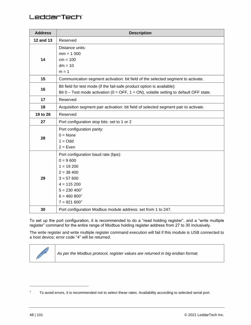
48 | 101 © 2021 LeddarTech Inc.
Address Description
12 and 13 Reserved
14
Distance units:
mm = 1 000
cm = 100
dm = 10
m = 1
15 Communication segment activation: bit field of the selected segment to activate.
16 Bit field for test mode (if the fail-safe product option is available):
Bit 0 – Test mode activation (0 = OFF, 1 = ON), volatile setting to default OFF state.
17 Reserved
18 Acquisition segment pair activation: bit field of selected segment pair to activate.
19 to 26 Reserved
27 Port configuration stop bits: set to 1 or 2
28
Port configuration parity:
0 = None
1 = Odd
2 = Even
29
Port configuration baud rate (bps):
0 = 9 600
1 = 19 200
2 = 38 400
3 = 57 600
4 = 115 200
5 = 230 4007
6 = 460 8007
7 = 921 6007
30 Port configuration Modbus module address: set from 1 to 247.
To set up the port configuration, it is recommended to do a “read holding register”, and a “write multiple register” command for the entire range of Modbus holding register address from 27 to 30 inclusively.
The write register and write multiple register command execution will fail if this module is USB connected to a host device; error code “4” will be returned.
As per the Modbus protocol, register values are returned in big-endian format.
7 To avoid errors, it is recommended not to select these rates. Availability according to selected serial port.

54A0040-7.0EN / Leddar M16 Laser – User Guide 49 | 101
A request for a register that does not exist will return the error code “2”. Trying to set up a register to an invalid value will return error code “3”. If an error occurs while trying to execute the function, error code “4” will be returned.
4.2. CAN Bus
The CAN bus in single message mode uses the 1872 (0x750) base ID to send all detection messages. When sending detection, one 0x751 message will be sent, followed by as many 1872 (0x750) base ID messages as needed.
The CAN port in multiple message mode uses a maximum range from 1874 (0x752) ID to 1922 (0x782) of standard message or a maximum range from 1874 (0x752) ID to 1970 (0x7B2) of the message with detection flag information. When sending detection, one 0x751 message will be sent, followed by messages on ID range from 1874 (0x752) to as needed in multiple message mode.
Four message IDs are available (these IDs can be modified with the Leddar Configurator software).
1856 (0x740) (Rx base ID)
This is an 8-byte message length for command request that the module listens to: the first byte (byte 0) describes the main function and the rest of message bytes are used as arguments. Undescribed bytes are reserved and must be set to 0.
Table 24: CAN bus request message
Function Request (Byte 0)
Function Request Description Function Argument (Byte 1)
1 Legacy: send detections once --
2
Legacy: start sending detections continu-ously (the module will send a new set of detections each time they are ready without waiting for a request).
--
3 Stop sending detections continuously. --
4 Send detection once.
Bit field of operation mode (this overrides the CAN operation mode field in CAN port configuration 3):
Bit 0: 0 = return detection in single message mode, 1 = return detection in multiple message mode
Bit 1: Reserved
Bit 2: Reserved
Bit 3: Detection flag message activation
5
Start sending detections continuously (that is, the module will send a new set of detections each time they are ready without waiting for a request).
Bit field of operation mode (this overrides the CAN operation mode field in CAN port configuration 3):
Bit 0: 0 = return detection in single message mode, 1 = return detection in multiple message mode
Bit 1: Reserved
Bit 2: Reserved
Bit 3: Detection flag message activation

50 | 101 © 2021 LeddarTech Inc.
Function Request (Byte 0)
Function Request Description Function Argument (Byte 1)
6 GET input data (read only) See Table 25.
7 GET holding data See Table 26.
8 SET holding data See Table 27.
The GET and SET function messages always return an answer message on the 1873 (0x751) base ID. See the section below.
Table 25: CAN bus request message (GET input data)
Input Data Type (Byte 1)
Input Data Description
0 Temperature
1 Device identification and option
2 Firmware version
3 FPGA version
4 to 9 Serial number
10 to 20 Device name
21 to 23 Software part number
24 to 26 Hardware part number
27 Detection zone
Table 26: CAN bus request message (GET holding data)
Holding Data Type (Byte 1)
Holding Data Description
0 Acquisition configuration
1 Reserved
2 Detection threshold
3 Laser power percent (%)
4 Acquisition option
5 Auto acquisition average frames
6 Smoothing
7 Distance resolution
8 Communication segment enabled
9 CAN port configuration 1
10 CAN port configuration 2
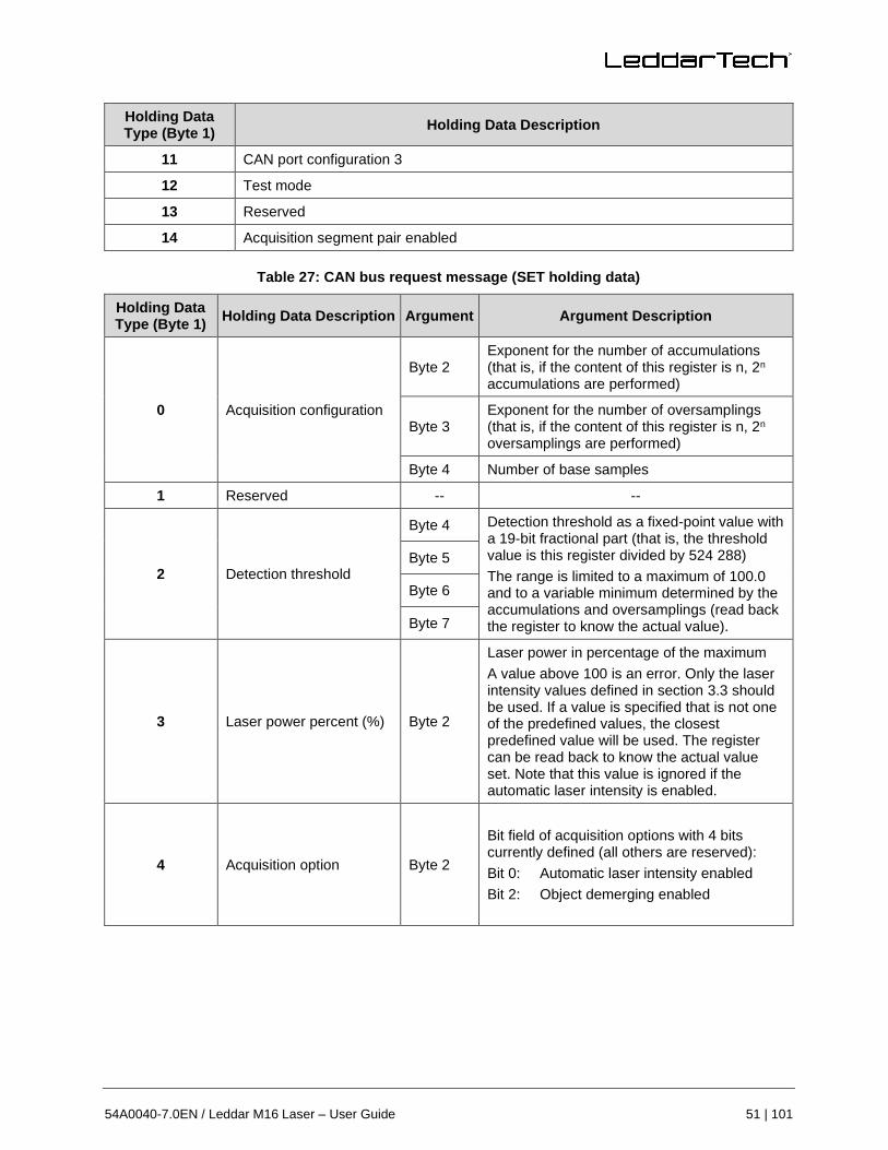
54A0040-7.0EN / Leddar M16 Laser – User Guide 51 | 101
Holding Data Type (Byte 1)
Holding Data Description
11 CAN port configuration 3
12 Test mode
13 Reserved
14 Acquisition segment pair enabled
Table 27: CAN bus request message (SET holding data)
Holding Data Type (Byte 1)
Holding Data Description Argument Argument Description
0 Acquisition configuration
Byte 2 Exponent for the number of accumulations (that is, if the content of this register is n, 2n accumulations are performed)
Byte 3 Exponent for the number of oversamplings (that is, if the content of this register is n, 2n oversamplings are performed)
Byte 4 Number of base samples
1 Reserved -- --
2 Detection threshold
Byte 4 Detection threshold as a fixed-point value with a 19-bit fractional part (that is, the threshold value is this register divided by 524 288)
The range is limited to a maximum of 100.0 and to a variable minimum determined by the accumulations and oversamplings (read back the register to know the actual value).
Byte 5
Byte 6
Byte 7
3 Laser power percent (%) Byte 2
Laser power in percentage of the maximum
A value above 100 is an error. Only the laser intensity values defined in section 3.3 should be used. If a value is specified that is not one of the predefined values, the closest predefined value will be used. The register can be read back to know the actual value set. Note that this value is ignored if the automatic laser intensity is enabled.
4 Acquisition option Byte 2
Bit field of acquisition options with 4 bits currently defined (all others are reserved):
Bit 0: Automatic laser intensity enabled
Bit 2: Object demerging enabled

52 | 101 © 2021 LeddarTech Inc.
Holding Data Type (Byte 1)
Holding Data Description Argument Argument Description
Byte 3
Bit 3: Crosstalk removal disabled (disabled if 1)
Bit 8: Automatic laser intensity mode:
0 = Mode 1
1 = Mode 2
Bit 9: Static detection threshold table usage disabled
Bit 10: Interference algorithm enabled
5 Auto acquisition average frames
Byte 2 Change delay in the number of measurements Byte 3
6 Smoothing Byte 2
Smoothing: used to stabilize the module measurements.
The behavior of the smoothing algorithm can be adjusted by a value ranging from −16 to 16. Select the Disabled check box or set the value to −17 to disable smoothing.
7 Distance units
Byte 2 Distance units:
mm = 1 000
cm = 100
dm = 10
m = 1 Byte 3
8 Communication segment enabled
Byte 2 Bit field of the activated segment for communication Byte 3
9 CAN port configuration 1
Byte 2
Baud rate (kbps):
0 = 1 000
1 = 500
2 = 250
3 = 125
4 = 100
5 = 50
6 = 20
7 = 10
Byte 3
Frame format:
0 = Standard 11 bits
1 = Extended 29 bits
Byte 4
Tx base ID Byte 5
Byte 6
Byte 7
10 CAN port configuration 2 Byte 4 Rx base ID

54A0040-7.0EN / Leddar M16 Laser – User Guide 53 | 101
Holding Data Type (Byte 1)
Holding Data Description Argument Argument Description
Byte 5
Byte 6
Byte 7
11 CAN port configuration 3
Byte 2
CAN operation mode bit field:
Bit 0: 0 = return detection in single message mode, 1 = return detection in multiple message mode
Bit 1: Inter-message delay activation
Bit 2: Inter-cycle delay activation
Bit 3: Detection flag message activation
Byte 3 Maximum number of detections (measurements) returned per CAN detection message transaction: 1 to 96
Byte 4 Inter-message delay, 0 to 65 535 milliseconds
Byte 5
Byte 6 Inter-cycle delay, 0 to 65 535 milliseconds
Byte 7
12 Test mode
Byte 2 Bit field for test mode (if the fail-safe product option is available):
Bit 0: Test mode activation (0 = OFF, 1 = ON), volatile setting to default OFF state
Byte 3
13 Reserved -- --
14 Acquisition segment pair enabled
Byte 2 Bit field of segment pair enabled for acquisition Byte 3
The SET command execution will fail if this module is USB connected to a host device; an error answer message will be returned.
1873 (0x751) (Tx Base ID + 1)
This is an 8-byte message that indicates the number of detections that will be sent or the answer to the GET and SET command requests.
Table 28: CAN bus answer message
Answer Data (Byte 0)
Answer Data Description Additional Answer Data (Byte 1 to Byte 7)
Equal to or less than 96
Number of detections See Table 29.

54 | 101 © 2021 LeddarTech Inc.
Answer Data (Byte 0)
Answer Data Description Additional Answer Data (Byte 1 to Byte 7)
128 + 6 Answer to GET input data request
Success: see the format in Table 30.
Fail: byte 2 to byte 7 are set to 0xFF.
128 + 7 Answer to GET holding data request
Success: see the format in Table 27.
Fail: byte 2 to byte 7 are set to 0xFF.
128 + 8 Answer to SET holding data request
Success: return echo of the SET command request.
Fail: byte 2 to byte 7 are set to 0xFF.
Table 29: CAN bus number of detection message
Data Data Return Description
Byte 0 Number of detections
Byte 1 Reserved
Byte 2 Current laser power as a percentage of maximum
Byte 3
Current acquisition statuses. This is an 8-bit field:
Bit 0: Reserved
Bit 1: Object demerging is completed if set to 1 when this function is activated.
Bit 2: Test mode detections (0 = standard detection, 1 = detection from test mode). This field is valid only if the fail-safe product option is available.
Byte 4
Timestamp of the acquisition. The timestamp is expressed as the number of milliseconds since the module was started.
Byte 5
Byte 6
Byte 7
Table 30: CAN bus answer message (GET input data)
Input Data Type (Byte 1)
Input Data Description Argument Argument Description
0 Temperature
Byte 4
Temperature as a fixed-point value with a 16-bit fractional part (that is, the temperature value is this register divided by 65 536)
Byte 5
Byte 6
Byte 7
1 Device identification and options
Byte 2 Device identification code (14 for M16 Laser module) Byte 3
Byte 4
Device option flags (LeddarTech internal use) Byte 5
Byte 6
Byte 7
2 Firmware version Byte 2 The firmware build version

54A0040-7.0EN / Leddar M16 Laser – User Guide 55 | 101
Input Data Type (Byte 1)
Input Data Description Argument Argument Description
Byte 3
Byte 4
The firmware 32-bit CRC Byte 5
Byte 6
Byte 7
3 FPGA version
Byte 2 The FPGA version
Byte 3
Byte 4 The firmware type (LeddarTech internal use)
Byte 5
Byte 6 Run status 0: OFF, 0xFF: ON. Should always return 0xFF; otherwise, the module is defective.
4 to 9 Serial number Byte 2 to byte 7
Serial number as an ASCII string (max. 32 bytes)
10 to 20 Device name Byte 2 to byte 7
The device name as a Unicode string (max. 64 bytes)
21 to 23 Software part number Byte 2 to byte 7
The software part number as an ASCII string (max. 16 bytes)
24 to 26 Hardware part number Byte 2 to byte 7
The hardware part number as an ASCII string (max. 16 bytes)
27 Detection zone
Byte 2 Detection zone outputs bit field (1 zone per bit)
Bit 0: object in advanced detection zone (0 = no detection in advanced detection zone, 1 = detection in advanced detection zone). Only this zone is currently available.
Byte 3
Byte 4
Reserved Byte 5
Byte 6
Byte 7
1872 (0x750) (Tx base ID)
This is an 8-byte message containing detection use in single message mode. Two types of messages are supported: standard detection message and detection message with flag information.
The standard detection message contains two detections: if the number of detections is odd, the last message will be 0 filled in the last 4 bytes. The message is separated in two parts with the same format:
• Data bytes 0 and 1 contain the distance in units defined by “distance units” holding data.
• Data byte 2 and the 4 LSBs of byte 3 contain the amplitude as a 12-bit value. This value must be divided by 4 to obtain the amplitude (that is, 2 bits for the fractional part).
The 4 MSBs of byte 3 contain the segment number.

56 | 101 © 2021 LeddarTech Inc.
Table 31: Standard CAN bus detection message
Byte 7 Byte 6 Byte 5 Byte 4 Byte 3 Byte 2 Byte 1 Byte 0
Segment (n+1)
Amplitude (n+1)
Distance (n+1)
Segment (n)
Amplitude (n)
Distance (n)
The detection message with flag information contains only one detection, and the format is as follows:
• Data bytes 0 and 1 contain the distance in units defined by “distance units” holding data.
• Data bytes 2 and 3 contain the amplitude. This value must be divided by 64 to obtain the amplitude (that is, 6 bits for the fractional part).
• Byte 4 contains the flag information, as described in Table 32 below.
Table 32: Flag information of measurement
Bit 0 Detection is valid (will always be set).
Bit 1 Detection was the result of object demerging.
Bit 2 Interference was detected in the current frame.
Bit 3 Detection is saturated.
Bit 4 Reserved
Bit 5 Reserved
Bit 6 Detection is within the crosstalk zone.
Bit 7 Reserved
Byte 5 contains the segment number.
Data bytes 6 and 7 are reserved.
Table 33: CAN bus detection message definition with flag information
Byte 7 Byte 6 Byte 5 Byte 4 Byte 3 Byte 2 Byte 1 Byte 0
-- -- Segment
(n) Flag (n)
Amplitude (n)
Distance (n)
1874 (0x752) (Tx base ID + 2)
This is an 8-byte message for multiple message mode using the same format as 0x750 message (see above). Detections are sent on a message ID range from 1874 to [1874 + (number of detections / 2) + (number of detections modulo)] in standard detection message and sent on a message ID range from 1874 to [1874 + number of detections] in detection message with flag information. The range of message IDs can be limited by the maximum amount of detections to output to CAN port.
Example: Module with 1874 base ID: 19 detections are sent.
• From 1874 to 1884 message ID in standard detection message
• From 1874 to 1882 message ID in standard detection message on a module setup of 16 maximum amount of detections
• From 1874 to 1893 message ID in detection message with flag information
• From 1874 to 1890 message ID in detection message with flag information on a module setup of 16 maximum amount of detections
For an example of a CAN bus detection request, refer to Appendix C.

54A0040-7.0EN / Leddar M16 Laser – User Guide 57 | 101
Leddar Configurator
The Leddar™ Configurator provides configuration parameters and operation functionalities for Leddar™ products.
5.1. Introduction
The Configurator interface can be resized manually or set to full-screen view.
All dialog boxes that do not include a selection of action buttons at the bottom, such as Connect, OK, Cancel, etc., are dockable at the top, the bottom, or on the right side of the main window.
Fig. 25: Raw Detections dialog box docked on the side of the main window
When a dialog box or a window is already open, a check mark appears next to the command on the menu.
5.2. Connection Window
The following is a description of the information shown in the Connection dialog box.
Fig. 26: Connection dialog box

58 | 101 © 2021 LeddarTech Inc.
Select a connection type
The connection type you are using.
The device list, in the center of the Connection dialog box, displays the devices currently detected.
Name
The device name can be modified (see section 5.4.1).
Serial Number
The serial number of the device as assigned by LeddarTech.
Type
The product name.
5.3. Leddar Configurator Main Window
After connecting to the device, the main window opens.
Fig. 27: Leddar Configurator main window
The measurements are plotted in a symbolic graph containing the 16 segments (white lines) originating from the module. Detections are drawn as arcs in their corresponding segments. Only valid measurements are displayed. A more detailed description of the measurements can be obtained in the Raw Detections dialog box (see section 5.11 on page 77).
The numbers X and Y displayed at the bottom are the mouse cursor position coordinates.
Vertical scale setting areas
Horizontal scale setting areas

54A0040-7.0EN / Leddar M16 Laser – User Guide 59 | 101
Toolbar Display Controls
The toolbar includes several buttons for adjusting the view of the main window display.
Fit to Window
When the Equal Scaling button is selected (button highlighted), the original ratio of the display is kept or restored. The horizontal and vertical scales will be set to the same values, and the beam will be displayed in accordance with the beam properties (for example, the display will show a 48° beam for a 48° module).
Click the button again to change the vertical and horizontal scales independently.
When in equal scaling mode, you cannot zoom the display horizontally or vertically. That is, holding the <Control> or <Shift> key down while zooming in or out will have no effect. The scales cannot then be modified by entering values in the fields shown in Fig. 26 above.
Force Equal Horizontal and Vertical Scales
When the Equal Scaling button is selected (button highlighted), the original ratio of the display is kept or restored. The horizontal and vertical scales will be set to the same values, and the beam will be displayed in accordance with the beam properties (for example, the display will show a 48° beam for a 48° module).
Click the button again to change the vertical and horizontal scales independently.
When in equal scaling mode, you cannot zoom the display horizontally or vertically. That is, holding the <Control> or <Shift> key down while zooming in or out will have no effect. The scales cannot then be modified by entering values in the fields shown in Fig. 26 above.
Zoom In
Click the Zoom In button to zoom in vertically and horizontally around the center of the display.
Zoom Out
Click the Zoom Out button to zoom out vertically and horizontally around the center of the display.
Scale
The window opens with the default scale setting. The horizontal and vertical scales can be changed manually by entering new values in the fields accessible by clicking the areas shown in Fig. 26 above.
To apply the changes, click anywhere in the main window.
Panning and Zooming
The display in the main window can be panned and zoomed in different ways. Panning and zooming is done relative to the mouse cursor position.
You can move up, down, and sideways by clicking and dragging the display.

60 | 101 © 2021 LeddarTech Inc.
To zoom the display in and out, use the mouse wheel alone. This has the same effect as clicking the
Zoom In or Zoom Out button, respectively (see sections 5.3.4 and 5.3.5 above).
To zoom the display horizontally, hold the <Control> key of the computer keyboard down while using the mouse wheel.
The Equal Scaling button must not be selected (not highlighted).
Fig. 28: Zooming in (left) and out (right) horizontally
To zoom the display vertically, hold the <Shift> key down while using the mouse wheel.
The Equal Scaling button must not be selected (not highlighted).
Fig. 29: Zooming in (left) and out (right) vertically

54A0040-7.0EN / Leddar M16 Laser – User Guide 61 | 101
The measurements of a detection point appear as a pop-up when you point to it with the mouse cursor for a more accurate assessment of the detection. Detection points are shown in the form of green lines (arcs) in the main window for visibility reasons.
Fig. 30: Detection point coordinates
Changing the Module Origin
The module origin can be modified by clicking the module origin at the bottom of the segments.
To do so, use the mouse cursor to point to the bottom of the segments (a red dot appears), then click and drag it to the desired position.
Fig. 31: Dot indicator to modify the module origin
If you click and drag the module origin, the module position is displayed in the status bar, as shown in Fig. 32 below.
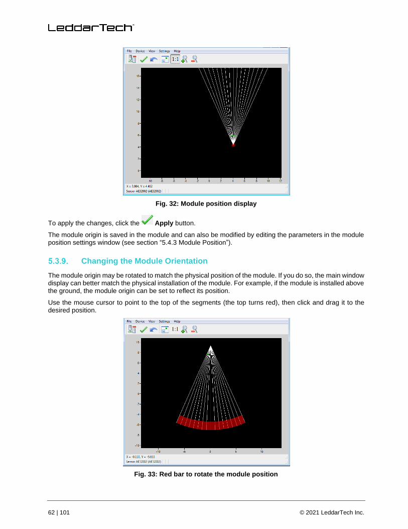
62 | 101 © 2021 LeddarTech Inc.
Fig. 32: Module position display
To apply the changes, click the Apply button.
The module origin is saved in the module and can also be modified by editing the parameters in the module position settings window (see section “5.4.3 Module Position”).
Changing the Module Orientation
The module origin may be rotated to match the physical position of the module. If you do so, the main window display can better match the physical installation of the module. For example, if the module is installed above the ground, the module origin can be set to reflect its position.
Use the mouse cursor to point to the top of the segments (the top turns red), then click and drag it to the desired position.
Fig. 33: Red bar to rotate the module position

54A0040-7.0EN / Leddar M16 Laser – User Guide 63 | 101
To apply the changes, click the Apply button.
The module orientation is saved in the module and can also be modified by editing the parameters in the module position settings window (see section “5.4.3 Module Position”).
5.4. Settings
The module stores several settings. Once saved in the module, these parameters are effective at each power-up. The Leddar Configurator software loads these parameters upon each connection.
Device Name
When you connect to a module for the first time, it has a default name. You can change that name at any time.
To change the device name:
1. Connect to a device.
2. In the Device menu, select Configuration, then click Device Name….
Fig. 34: Device menu – Configuration menu items
3. In the Name field of the Device Name dialog box, enter the new name of the device and click OK.
Fig. 35: Device Name dialog box
4. To apply the change, click the Apply button in the Leddar Configurator main window.

64 | 101 © 2021 LeddarTech Inc.
Acquisition Settings
The Acquisition Settings function allows you to define parameters to use for detection and distance measurement.
To open the Acquisition Settings dialog box, select Device, then Configuration, then Acquisition.
Fig. 36: Acquisition Settings dialog boxes
To apply the changes, click the Apply button in the main window.
Refer to section 3.3 on page 30 for more details on all the parameters.
Module Position
The Module Position function allows you to define the module position with respect to the reference of the system it is used in. See sections 5.3.8 and 5.3.9 above for more details.
To open the Module Position dialog box, in the Device menu, select Configuration, then click Position.
Fig. 37: Device menu – Sensor Position dialog box
Change the numbers either by using the arrows or by entering the value manually.
Click the Reset to defaults button to re-place the segments to their original manufacturing positions.

54A0040-7.0EN / Leddar M16 Laser – User Guide 65 | 101
Advanced Detection Zones
An Advanced Detection Zone is a configurable setting that allows you to display detections only if they are located in the specified zone.
To open the Advanced Detection Zones dialog box, in the Device menu, select Configuration, then click Advanced Detection Zones….
Fig. 38: Device menu – Configuration and Advanced Detection Zones menu items
In the Advanced Detection Zones dialog box, enter configuration lines to define the zone of interest.
Fig. 39: Advanced Detection Zones dialog box
Rise Debouncing
Number of frames during which there is a detection in the detection zone necessary to output a bit of “presence”.
Fall Debouncing
Number of frames during which there is no detection in the detection zone necessary to output a bit of “no presence”.
General
The module’s General communication settings are configurable.
To open the General Settings dialog box, in the Device menu, select Configuration, then Communication, then click General.

66 | 101 © 2021 LeddarTech Inc.
Fig. 40: Device menu – Configuration and Communication menu items
In the General Settings dialog box, in the Distance Units list, select the units with which you want to work.
Fig. 41: General Settings dialog box
The number of channels used is set to 16 by default, but you can remove some of them to suit your application through the LeddarHost dialog box. Next to Channel Select, click Modify and clear the desired check boxes.
In Modbus and CAN communications, you can either enable or disable one or more channels.
Fig. 42: LeddarHost dialog box
Serial Ports
The module’s serial port settings are configurable.
To open the Serial Ports Settings dialog box, in the Device menu, select Configuration, then Communication, then click Serial Ports.

54A0040-7.0EN / Leddar M16 Laser – User Guide 67 | 101
Fig. 43: Device menu – Configuration and Communication menu items
In the Serial Port Settings dialog box, you can change the numbers by using the arrows or by entering the value manually.
Fig. 44: Serial Ports Settings dialog box
The Detections parameter can be limited to 40 if used with a 0x6A Modbus function.
The following table describes the serial port settings.
Table 34: Serial port settings description
Parameter Value
Port Number Select 1 for the RS-485 port on the terminal block.
Select 2 for the expansion connector.
Baud Rate (bps)
9 600
19 200
38 400
57 600
115 200
230 4008
460 8008
8 To avoid errors, it is recommended not to select these rates. Availability according to selected serial port.

68 | 101 © 2021 LeddarTech Inc.
Parameter Value
921 6008
Parity
None
Odd
Even
Stop Bits 1
2
Address 1 to 247
Detections9 0 to 48
CAN Ports
The module CAN port settings are configurable.
To open the CAN Port Settings dialog box, in the Device menu, select Configuration, then Communication, then click CAN Ports.
Fig. 45: Device menu – Configuration and Communication menu items
In the CAN Port Settings dialog box, you can change the numbers by using the arrows or by entering the value manually.
9 This parameter can be limited to 40 if used with a 0x6A Modbus function.
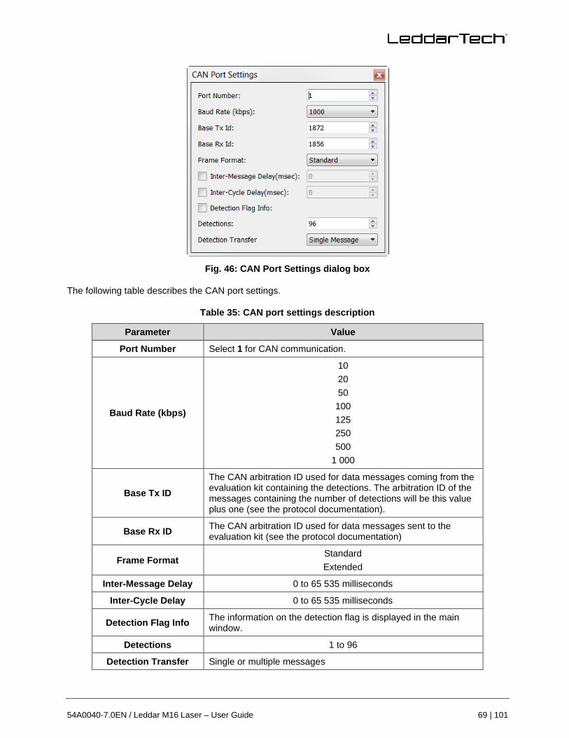
54A0040-7.0EN / Leddar M16 Laser – User Guide 69 | 101
Fig. 46: CAN Port Settings dialog box
The following table describes the CAN port settings.
Table 35: CAN port settings description
Parameter Value
Port Number Select 1 for CAN communication.
Baud Rate (kbps)
10
20
50
100
125
250
500
1 000
Base Tx ID
The CAN arbitration ID used for data messages coming from the evaluation kit containing the detections. The arbitration ID of the messages containing the number of detections will be this value plus one (see the protocol documentation).
Base Rx ID The CAN arbitration ID used for data messages sent to the evaluation kit (see the protocol documentation)
Frame Format Standard
Extended
Inter-Message Delay 0 to 65 535 milliseconds
Inter-Cycle Delay 0 to 65 535 milliseconds
Detection Flag Info The information on the detection flag is displayed in the main window.
Detections 1 to 96
Detection Transfer Single or multiple messages

70 | 101 © 2021 LeddarTech Inc.
5.5. Saving and Loading a Configuration
The software configuration for a device can be saved to a file. This enables you to back up settings and restore them in case of a system failure or in case you want to revert to earlier settings. You can also retrieve the configuration that was stored with a record file.
To save a configuration:
In the File menu, click Save Configuration….
Fig. 47: File menu
To load a configuration:
In the File menu, click Load Configuration….
5.6. Configuring Detection Records
Detection records provide playback of detections recorded by a device. This visual information can be useful for verification, troubleshooting, or training purposes. Detection records allow for a full data playback stored in a *.ltl file that can later be reloaded and replayed.
To configure the detection record:
1. In Leddar Configurator, select the Settings menu, then click Preferences….
Fig. 48: Settings menu
2. In the Preferences dialog box, click Recording, then Recorder.

54A0040-7.0EN / Leddar M16 Laser – User Guide 71 | 101
Fig. 49: Preferences dialog box
3. Under Directory, click the Browse button to select the path where you want to save the detection record file.
4. In the Maximum file size box, set the maximum file size by using the arrows or by entering the value manually.
5. Under What?, select the Log debug information check box.
6. Under How Long?, next to Maximum record time (minutes), set the length of time for recording by using the arrows or by entering the value manually. At the end of that period, the recording will stop even if the file size has not reached its maximum.
7. Click OK to save the settings.
A complete description of the elements found in the recording Preferences dialog box follows the next two procedures.
To start a recording:
In the File menu, click Start Recording.
Fig. 50: File menu
To stop a recording manually:
In the File menu, click Stop Recording.

72 | 101 © 2021 LeddarTech Inc.
Fig. 51: File menu to stop a recording
The following is a description of the elements available in the recording Preferences dialog box.
Record directory
The record directory is the folder in which all record files will be saved. These files are in a proprietary format, with the extension *.ltl, and can only be opened and viewed with the Leddar Configurator software.
Maximum file size
Record files can be quite large. Set the maximum file size as needed. The recording stops for the current file once it reaches the maximum file size and automatically switches the recording to another file. This is to keep record files of manageable sizes.
Debug
These check boxes are reserved for the use of LeddarTech debug purposes.
Maximum record time
The value entered as the Maximum record time defines the length of the time for recording. At the end of that period, the recording will stop even if the file size has not reached its maximum.
5.7. Using Detection Records
Once you have completed a recording, you can review it and extract part of the recording.
The Record Replay dialog box offers the same functions as a regular video player: a stop button, a play button, and frame-by-frame forward and backward buttons are available.
The Position slider lets you move directly to the desired position.
The Playback Speed slider lets you adjust the speed of the recording playback; faster is to the left.
The Start, End, and Extract buttons allow you to select a portion of the recording and extract it for further reference or analysis.
To play a record:
1. If you are connected to a device, disconnect from the device.
Another option is to open another Leddar Configurator main window.
The record files can also be opened by double-clicking them.
2. In the File menu, click Replay….

54A0040-7.0EN / Leddar M16 Laser – User Guide 73 | 101
Fig. 52: File menu to open a recording
3. In the Record Replay dialog box, click the Browse… button to select a file.
Fig. 53: Record Replay dialog box
4. Click the Play button to start the playback.
To extract a record file segment:
1. Set the Position slider to the position where you want the file segment to start and click the Start button.
2. Set the Position slider to the position where you want the file segment to stop and click the End button.
OR
Play the record and stop it at a position of interest then click the Start button; restart playing the record and stop it again at a position of interest, then click the Stop button.
3. Click the Extract button to extract and save that file segment.
5.8. Data Logging
The Data Logging function is used to output the data to a .txt file. This file can be imported to a software application (such as Microsoft Excel) for offline analysis.
The duration of the record is indicated in the status bar.
Each line of the generated text file contains the information related to a single detection.
Table 36: Field description of the log text file
Time (msec) Segment [0 15] Amplitude [0 512] Distance (m) Status
12 735 204 7 0.9 33.61 1
Play button

74 | 101 © 2021 LeddarTech Inc.
In this table:
• Time indicates the timestamp of the detection from when the module was connected to the power supply.
• Segment refers to the location of the detection (line, column).
• Amplitude of the detection indicates the strength of the returned signal.
• Distance indicates the distance of the detection in meters or feet depending on the distance unit configured in the Preferences menu.
• Status corresponds to a flag value. Refer to section “5.11 Raw Detections” for more details.
To use the data logging function:
1. In the Settings menu of Leddar Configurator, click Preferences….
Fig. 54: Settings menu
2. In the Preferences dialog box, select Recording, then click Data Logger.
Fig. 55: Preferences dialog box for logging data
3. Under Directory, click the Browse… button to select the path where you want to save the log and click OK.
4. In the File menu, click Start Data Logging.
Fig. 56: File menu

54A0040-7.0EN / Leddar M16 Laser – User Guide 75 | 101
5. To stop recording, click Stop Data Logging in the File menu.
Fig. 57: File menu to stop data recording
A .txt file is saved in the selected directory.
5.9. Device State
Information about a device is accessible when connecting to a device in the Connection window or by clicking the State command in the View menu.
Fig. 58: View menu
The Device State window opens.
Fig. 59: Device State window
Temperature
This section indicates the temperature of the device.

76 | 101 © 2021 LeddarTech Inc.
Timers & Load
This feature provides information on the time elapsed since the last module reset in days, hours, minutes, and seconds.
The CPU Load indicates how much of the module processor capacity is in use. When the load reaches nearly 100%, the processor may no longer be able to process all the data. The effective frame rate may be impacted.
The Measurement Rate indicates the rate at which the module measures the speed and dimension of static or moving surfaces.
Device Information
The Serial Number is the number of the device as assigned by LeddarTech.
The Version includes the following:
• FPGA: The firmware version of the device.
• Software: The software version of the device.
• CRC: Indicates the firmware version to ensure that it is authentic.
The Part Numbers provide the hardware and software part numbers of a device as assigned by LeddarTech.
The LED Intensity (laser intensity) is the current laser power in use by the module. It automatically adapts to too strong/too weak detections when properly activated in the Acquisition settings dialog box.
Demerging indicates the current object demerging status when activated in the acquisition settings. It may be:
• Partial: When the demerge module did not process all pulses characteristic of merged objects.
• Completed: When the module processed all pulses characteristic of merged objects.
5.10. Preferences
Preferences are used to change various settings related to the display of Leddar Configurator.
Open the Preferences dialog box by clicking the Preferences… command in the Settings menu.
Fig. 60: Settings Menu – Preferences dialog box

54A0040-7.0EN / Leddar M16 Laser – User Guide 77 | 101
Windows
The following two options allow you to select how the content of the main window will be displayed in Leddar Configurator.
• The Restore window position and size on startup option starts Leddar Configurator at the same place on the computer desktop and at the same size it was when it was closed.
• The Restore window layout on connection option connects to the evaluation kit at the same size it was and with all docked dialog boxes or windows that were displayed when it was closed.
Units
The unit that is applied to distances displayed in Leddar Configurator.
The temperature is the unit used when displaying temperatures.
Recording
The Recorder parameter lets you choose how data files are recorded.
The Data Logger parameter lets you select a directory to store logs.
Display
The Detection Arc Thickness parameter allows you to modify the pixel width of the displayed green detection arcs in the main window.
5.11. Raw Detections
The Raw Detections dialog box allows you to view detection values in many ways. It provides filters to isolate segments and detection parameters.
To open the Raw Detections dialog box, click Raw Detections in the View menu.
Fig. 61: View menu – Raw Detections dialog box

78 | 101 © 2021 LeddarTech Inc.
Fig. 62 shows an example of raw detections. When there is no detection in some segments, only the segments where detection occurred appear in the list.
Fig. 62: Example of detection filtering in the Raw Detections dialog box
The following is a description of the parameters in the Raw Detections dialog box.
Min and Max Amplitude
The value entered in the Min Amplitude field shows only detections of amplitude higher than or equal to that value in meters. For example, if the minimum amplitude is set to 5, only the detections of amplitude 5 and higher will be displayed.
The value entered in the Max Amplitude field will show only detections of amplitude lower than or equal to that value in meters. For example, if the maximum amplitude is set to 8, only the detections of amplitude 8 and lower will be displayed.
Setting a value in both fields will result in a range of amplitude to display.
Min and Max Distance
The value entered in the Min Distance field will show only detections at a distance greater than or equal to that value. For example, if the minimum distance is set to 10, only the detections at a distance of 10 and more will be displayed.
The value entered in the Max Distance field will show only detections at a distance smaller than or equal to that value. For example, if the minimum distance is set to 20, only the detections at 20 and less will be displayed.
Setting a value in both fields will result in a range of distance to display.
Check boxes 1 to 16
Check boxes 1 to 16 allow you to select which segments to display.
Freeze
When selected, the Freeze parameter allows you to freeze the values displayed in the Raw Detections dialog box. To return to the live display, clear the check box.

54A0040-7.0EN / Leddar M16 Laser – User Guide 79 | 101
Seg
The Seg column lists the segment for which there is a detection according to the filters used. The segment numbers are read from left to right starting at 1.
Distance and Amplitude
The Distance column displays the distance of the detection, and the Amplitude column displays its amplitude.
Flag
The Flag column displays a number that represents a detection type. See Table 37.
Table 37: Flag value description
Bit position Bit 0 Bit 1
0 Invalid measurement Valid measurement
1 Reserved Reserved
2 Normal measurement Interference was detected in the current frame.
3 Normal measurement
Received signal is above the saturation level.
Measurements are valid (VALID is set) but have lower accuracy and precision.
Consider decreasing the laser intensity.
4 Reserved Reserved
5 Reserved Reserved
6 Normal measurement Detection is within the crosstalk zone.
7 Reserved Reserved
The Flag field provisions for 8 bits encoded as a bit field. Three bits are currently used. The following table lists the implemented decimal values of the status bit field.
Table 38: Status value description
Status Value (Decimal) Status Value (Binary) Description
1 00000001 Normal measurement (valid)
9 00001001 Saturated signal (valid)
5.12. View Serial Port Data
When using a device through a serial port (for example, using an RS-485 to USB adapter cable), it is possible to establish a connection to the module and display the module measurements in Leddar Configurator.
To view the serial port data:
1. In the View menu, click Serial Port Viewer.

80 | 101 © 2021 LeddarTech Inc.
Fig. 63: View menu – Preferences dialog box
2. In the Port list of the Serial Port Viewer dialog box, select the serial port of the connected module.
Fig. 64: Serial Port Viewer dialog box
3. Click the Start button to establish the connection and display the measurements.

54A0040-7.0EN / Leddar M16 Laser – User Guide 81 | 101
Fig. 65: Serial port measurement

82 | 101 © 2021 LeddarTech Inc.
Specifications
6.1. General
Table 39: General specifications
Model
M16R-75J0012 (19° x 0.3°)
M16R-75J0003 (19° x 3°)
M16R-75J0002 (36° x 0.2°)
M16R-75J0007 (48° x 0.3°)
M16R-75J0008 (48° x 3°)
M16R-75J0001-2 (48° x 5.1°)
M16R-75J0011-1 (48° x 5.5°)
M16R-75J0009 (99° x 0.3°)
M16R-75J0010 (99° x 3°)
Dimensions (mm, D x H x L)
71 x 64 x 76 74 x 64 x 66 62 x 64 x 66 62 x 64 x 66
Weight (g) 255 175 162 182
Interface USB, RS-485, CAN, UART
Power supply 12 V to 30 V
Power consumption >4 W
6.2. Environmental
Table 40: Environmental specifications
Operating temperature −40 °C to +85 °C
Storage temperature −40 °C to +85 °C
Relative humidity 5% to 95%
Vibration resistance (unpacked)
Sinusoidal vibrations, 5 to 200 Hz at 1 G, constant amplitude 0.3 cm, 1 oct./min
Mechanical shocks (unpacked)
½ sine 30 G, 11 ms, 3 shocks per direction and axis
6.3. Regulatory Compliance
The M16 LSR complies with the following standards:
• FCC Class B
• RoHS
• CE (EMC Class B or EN 60950)
• Laser eye safety Class 1 (IEC-60825: 2014)

54A0040-7.0EN / Leddar M16 Laser – User Guide 83 | 101
6.4. Optical
Table 41: Optical specifications
Features
Model Beam width,
horizontal FoV Beam height, vertical FoV
Laser pulse rate (Hz)
Photodetector array size
Wavelength Laser risk
group
M16R-75J0001-2
48° 5.1°
51 200
1 x 16 905 nm
(infrared)
IEC 60825-1:2014 (3rd
Ed.), Class 1 laser product
M16R-75J0002
36° 0.2°
M16R-75J0003
19° 3°
M16R-75J0007
48° 0.3°
M16R-75J0008
48° 3°
M16R-75J0009
99° 0.3°
M16R-75J0010
99° 3°
M16R-75J0011-1
48° 5.5°
M16R-75J0012
19° 0.3° 12 800
Fig. 66: Horizontal field of view (HFoV) and vertical field of view (VFoV)

84 | 101 © 2021 LeddarTech Inc.
6.5. Performance
Table 42: Module performances
Performance Metrics and Values
Model
Max. ra
ng
e w
ith
retr
ore
flecto
r (m
)10, 1
1
Max. ra
ng
e w
ith
wh
ite t
arg
et
(m)1
2, 11
Max. ra
ng
e w
ith
gra
y t
arg
et
(m)1
3
Measu
rem
en
t
accu
racy
14 (
cm
)
Measu
rem
en
t
pre
cis
ion
(m
m)
Measu
rem
en
t ra
te
(Hz)
Measu
rem
en
t
reso
luti
on
(cm
)
Ran
ge (
max. la
ser
inte
nsit
y v
alu
e)
M16R-75J0001-2 (48° x 5.1°)
60 16 10
± 5 ± 6 Up to 10015
± 1
Varies with beam optics and target properties
(see amplitude vs. range figures
below)
M16R-75J0002
(36° x 0.2°) 146 37 20
M16R-75J0003 (19° x 3°)
110 31 18
M16R-75J0007
(48° x 0.3°) 118 31 18
M16R-75J0008 (48° x 3°)
85 19 13
M16R-75J0009
(99° x 0.3°) 61 12 7
M16R-75J0010 (99° x 3°)
34 9 6
M16R-75J0011-1 (48° x 5.5°)
91 23 13
M16R-75J0012
(19° x 0.3°)
165 41 25
10 Retroreflector reference target corresponds to a 5 cm x 7 cm strip of reflective tape. 11 Ranges are evaluated at 32 accumulations and 8 oversamplings. 12 White reference target corresponds to a 20 cm x 25 cm Kodak gray card with 90% reflectivity. 13 Gray reference target corresponds to a 20 cm x 25 cm Kodak grey card with 18% reflectivity. 14 For oversampling of 4 and more. 15 See Table 13 on page 36 for typical measurement rate calculation.

54A0040-7.0EN / Leddar M16 Laser – User Guide 85 | 101
6.6. Dimensions
36° x 0.2° Module (M16R-75J0002)
Fig. 67: 36° x 0.2° module dimensions

86 | 101 © 2021 LeddarTech Inc.
19° x 0.3° Module (M16R-75J0012)
Fig. 68: 19° x 0.3° module dimensions

54A0040-7.0EN / Leddar M16 Laser – User Guide 87 | 101
19° x 3° Module (M16R-75J0003)
Fig. 69: 19° x 3° module dimensions

88 | 101 © 2021 LeddarTech Inc.
48° x 0.3° Module (M16R-75J0007)
Fig. 70: 48° x 0.3° module dimensions

54A0040-7.0EN / Leddar M16 Laser – User Guide 89 | 101
48° x 3° Module (M16R-75J0008)
Fig. 71: 48° x 3° module dimensions

90 | 101 © 2021 LeddarTech Inc.
48° x 5.1° Module (M16R-75J0001)
Fig. 72: 48° x 5.1° module dimensions

54A0040-7.0EN / Leddar M16 Laser – User Guide 91 | 101
48° x 5.5° Module (M16R-75J0011-1)
Fig. 73: 48° x 5.5° module dimensions

92 | 101 © 2021 LeddarTech Inc.
99° x 0.3° Module (M16R-75J0009)
Fig. 74: 99° x 0.3° module dimensions

54A0040-7.0EN / Leddar M16 Laser – User Guide 93 | 101
99° x 3° Module (M16R-75J0010)
Fig. 75: 99° x 3° module dimensions

94 | 101 © 2021 LeddarTech Inc.
Troubleshooting
Contact LeddarTech for troubleshooting information concerning the M16 LSR sensor module.
Maintenance
Manipulation Avoid touching the optical surfaces as fingerprints can permanently damage the optical coatings.
Cleaning the optical surfaces
• Blow off dust using compressed air.
• Clean the optical surfaces with a soft cloth and mild soap.
Do not pressure wash the sensor module.
For any questions or concerns on how to safely perform maintenance operations on the M16 LSR sensor module, contact LeddarTech support at [email protected].
Disposal
Like any electronic equipment, the M16 LSR sensor module contains environmentally unsustainable components. Dispose of in an environmentally responsible manner.
Technical Support
For technical enquiries, contact LeddarTech technical support at [email protected] to easily:
• follow up on your requests
• find quick answers to questions
• get valuable updates
Also, see the contact information at the end of this document.
Please have all relevant information such as part numbers, serial numbers, and pictures to facilitate support.

54A0040-7.0EN / Leddar M16 Laser – User Guide 95 | 101
Appendix A. Example of a 0x41 Modbus Function
Transmit data stream message
01 41 C0 10
Use the 0x41 command to read the Modbus address # 01, using the CRC C0 10.
Received data stream message
01 41 10 CA 01 58 04 01 DA 01 2F 04 11 C0 01 94 04 21 D0 01 2F 04 31 B6 01 BF 04 41 C6 01 76 04 51 B3 01 D5 04 61 C7 01 7E 04 71 AE 01 EB 04 81 C2 01 93 04 91 AD 01 F5 04 A1 C6 01 55 04 B1 B2 01 F1 04 C1 CC 01 48 04 D1 B0 01 DA 04 E1 D3 01 2D 04 F1 CF 61 02 00 64 03 0F DB
Get detection messages (first byte)
Modbus address: 01 hex = 1 = address#1 Function code: 41 hex = 65 = function 0x41 Number of detections: 10 hex = 16 = 16 detections
Get detection messages (detection fields); refer to Table 17 on page 43.
(1) CA 01 58 04 01:
Distance (cm): 01 CA hex = 458 cm Amplitude (count): 04 58 hex = 1112 / 64 = 17.375 counts Segment/Flags #: 01 hex (segment #0, flag = valid)
(2) DA 01 2F 04 11:
Distance (cm): 01 DA hex = 474 cm Amplitude (count): 04 2F hex = 1071 / 64 = 16.734 counts Segment/Flags #: 11 hex (segment #1, flag = valid)
(3) C0 01 94 04 21:
Distance (cm): 01 C0 hex = 448 cm Amplitude (count): 04 94 hex = 1172 / 64 = 18.313 counts Segment/Flags #: 21 hex (segment #2, flag = valid)
(4) D0 01 2F 04 31:
Distance (cm): 01 D0 hex = 464 cm Amplitude (count): 04 2F hex = 1071 / 64 = 16.734 counts Segment/Flags #: 31 hex (segment #3, flag = valid)
(5) B6 01 BF 04 41:
Distance (cm): 01 B6 hex = 438 cm Amplitude (count): 04 BF hex = 1215 / 64 = 18.984 counts Segment/Flags #: 41 hex (segment #4, flag = valid)
(6) C6 01 76 04 51:
Distance (cm): 01 C6 hex = 454 cm Amplitude (count): 04 76 hex = 1142 / 64 = 17.844 counts Segment/Flags #: 51 hex (segment #5, flag = valid)
(7) B3 01 D5 04 61:
Distance (cm): 01 B3 hex = 435 cm Amplitude (count): 04 D5 hex = 1117 / 64 = 17.453 counts Segment/Flags #: 61 hex (segment #6, flag = valid)

96 | 101 © 2021 LeddarTech Inc.
(8) C7 01 7E 04 71:
Distance (cm): 01 C7 hex = 455 cm Amplitude (count): 04 7E hex = 1150 / 64 = 17.969 counts Segment/Flags #: 71 hex (segment #7, flag = valid)
(9) AE 01 EB 04 81:
Distance (cm): 01 AE hex = 430 cm Amplitude (count): 04 EB hex = 1259 / 64 = 19.671 counts Segment/Flags #: 81 hex (segment #8, flag = valid)
(10) C2 01 93 04 91:
Distance (cm): 01 C2 hex = 450 cm Amplitude (count): 04 93 hex = 1171 / 64 = 18.267 counts Segment/Flags #: 91 hex (segment #9, flag = valid)
(11) AD 01 F5 04 A1:
Distance (cm): 01 AD hex = 429 cm Amplitude (count): 04 F5 hex = 1119 / 64 = 17.484 counts Segment/Flags #: A1 hex (segment #10, flag = valid)
(12) C6 01 55 04 B1:
Distance (cm): 01 C6 hex = 454 cm Amplitude (count): 04 55 hex = 1109 / 64 = 17.328 counts Segment/Flags #: B1 hex (segment #11, flag = valid)
(13) B2 01 F1 04 C1:
Distance (cm): 01 B2 hex = 434 cm Amplitude (count): 04 F1 hex = 1115 / 64 = 17.422 counts Segment/Flags #: C1 hex (segment #12, flag = valid)
(14) CC 01 48 04 D1:
Distance (cm): 01 CC hex = 460 cm Amplitude (count): 04 48 hex = 1096 / 64 = 17.125 counts Segment/Flags #: D1 hex (segment #13, flag = valid)
(15) B0 01 DA 04 E1:
Distance (cm): 01 B0 hex = 432 cm Amplitude (count): 04 DA hex = 1242 / 64 = 19.406 counts Segment/Flags #: E1 hex (segment #14, flag = valid)
(16) D3 01 2D 04 F1:
Distance (cm): 01 D3 hex = 467 cm Amplitude (count): 04 2D hex = 1069 / 64 = 16.703 counts Segment/Flags #: F1 hex (segment #15, flag = valid)
Get detection messages (trailing fields); refer to Table 18 on page 44.
CF 61 02 00 64 03 0F DB: TimeStamp (ms): 00 02 61 CF hex = 156111 ms = 156 s. Light source POWER (%): 64 hex = 100 = 100% Bit field acq. (reserved): 00 hex = 0 CRC (16-bits Modbus) = 0F DB

54A0040-7.0EN / Leddar M16 Laser – User Guide 97 | 101
Appendix B. Example of a 0x04 Modbus
Transmit message
01 04 00 00 00 30 F0 1E
Use the 0x04 command to read 48 consecutive registers starting at address 00. On device with Modbus address 01, using the CRC F0 E1.
Received message
01 04 60 2D 00 00 01 00 00 00 00 00 00 00 00 00 00 00 00 00 00 00 00 00 00 00 00 00 00 01 64 89 9B 00 2B 01 CB 01 DF 01 C3 01 D4 01 BB 01 CC 01 B5 01 CA 01 B0 01 C5 01 AE 01 CA 01 B4 01 D2 01 B3 01 D9 04 00 03 EB 04 30 03 D0 04 4D 04 08 04 6C 04 09 04 77 04 21 04 84 03 E8 04 85 03 D8 04 6E 03 DD FA 29
Header
(Address 0) Module temperature: 2D 00 hex = 11520/256 = 45.0°C (1) Status for polling mode: 00 01 hex = 1 = Detections ready (13) Light source power & Acquisition statuses: 01 64 hex, acquisition status = 01 hex = automatic light power, light source power = 64 hex = 100 = 100% (14&15) TimeStamp: 00 2B 89 9B hex = 2853275 = 2853275 ms (2853 s)
Modbus footer
Modbus CRC-16: FA 29 hex
Distance (first detection only)
(Address 16) Segment #0 = 01 CB hex = 459 cm (17) Segment #1 = 01 DF hex = 479 cm (18) Segment #2 = 01 C3 hex = 451 cm (19) Segment #3 = 01 D4 hex = 468 cm (20) Segment #4 = 01 BB hex = 443 cm (21) Segment #5 = 01 CC hex = 460 cm (22) Segment #6 = 01 B5 hex = 437 cm (23) Segment #7 = 01 CA hex = 458 cm (24) Segment #8 = 01 B0 hex = 432 cm (25) Segment #9 = 01 C5 hex = 453 cm (26) Segment #10 = 01 AE hex = 430 cm (27) Segment #11 = 01 CA hex = 458 cm (28) Segment #12 = 01 B4 hex = 436 cm (29) Segment #13 = 01 D2 hex = 466 cm (30) Segment #14 = 01 B3 hex = 434 cm (31) Segment #15 = 01 D9 hex = 473 cm
Amplitude (first detection only)
(Address 32) Segment #0 = 04 00 hex = 1024 / 64 = 16 counts (33) Segment #1 = 03 EB hex = 1003 / 64 = 15.672 counts (34) Segment #2 = 04 30 hex = 1072 / 64 = 16.75 counts (35) Segment #3 = 03 D0 hex = 976 / 64 = 15.25 counts (36) Segment #4 = 04 4D hex = 1101 / 64 = 17.203 counts (37) Segment #5 = 04 08 hex = 1032 / 64 = 16.125 counts (38) Segment #6 = 04 6C hex = 1132 / 64 = 17.688 counts (39) Segment #7 = 04 09 hex = 1033 / 64 = 16.140 counts (40) Segment #8 = 04 77 hex = 1143 / 64 = 17.859 counts (41) Segment #9 = 04 21 hex = 1057 / 64 = 16.516 counts (42) Segment #10 = 04 84 hex = 1156 / 64 = 18.063 counts (43) Segment #11 = 03 E8 hex = 1000 / 64 = 15.625 counts

98 | 101 © 2021 LeddarTech Inc.
(44) Segment #12 = 04 85 hex = 1157 / 64 = 18.078 counts (45) Segment #13 = 03 D8 hex = 984 / 64 = 15.375 counts (46) Segment #14 = 04 6E hex = 1134 / 64 = 17.719 counts (47) Segment #15 = 03 DD hex = 989 / 64 = 15.453 counts

54A0040-7.0EN / Leddar M16 Laser – User Guide 99 | 101
Appendix C. Example of a CAN Bus Detection Request
The controller sends the following:
ID Data
0740 01
This message sends a request to receive the module detections only once.
The Leddar module answers the following:
ID Data
0751 0F
0750 BD 00 85 00 C8 00 CA 10
0750 CE 00 AD 21 CB 00 3A 32
0750 C8 00 A1 42 C6 00 ED 52
0750 C4 00 FB 62 C5 00 2C 73
0750 C6 00 3A 85 C7 00 EC 92
0750 C6 00 7D A2 C9 00 0D B2
0750 CD 00 72 C1 CE 00 3F D1
0750 D1 00 5F E1 00 00 00 00
The following explains the first three lines of the answer:
ID: 0751 Data: 0F
0751 indicates that the data in this message will be the number of sent detections.
The number of sent detections is 0F hex = 15 detections; therefore, there are seven 0750 messages each containing two detections and one 0750 message containing only one detection.
ID: 0750 Data: BD 00 85 00 C8 00 CA 10
0750 = 8-byte message containing two detections.
Detection 1:
Distance is 00 BD hex = 189 cm
Amplitude is 085 hex/4 = 133/4 = 33.25
Channel is 0
Detection 2:
Distance is 00 C8 hex = 200 cm
Amplitude is 0 CA hex / 4 = 202/4 = 50.25
Channel is 1
ID: 0750 Data: CE 00 AD 21 CB 00 3A 32
0750 = 8-byte message containing two detections.

100 | 101 © 2021 LeddarTech Inc.
Detection 1:
Distance is 00 CE hex = 206 cm
Amplitude is 1 AD hex / 4 = 429/4 = 107.25
Channel is 2
Detection 2:
Distance is 00 CB hex = 203 cm
Amplitude is 2 3A hex / 4 = 570/4 = 142.5
Channel is 3

LEDDARTECH INC.
www.leddartech.com
HEADQUARTERS
4535, boulevard Wilfrid-Hamel, Suite 240
Québec (Québec) G1P 2J7, Canada
Phone: + 1-418-653-9000
Canada or USA (toll-free): + 1-855-865-9900
CANADA – USA – AUSTRIA – FRANCE – GERMANY – ITALY – ISRAEL – HONG KONG – CHINA
More information on our offices worldwide can be found at: leddartech.com/contact-us
Leddar, LeddarTech, LeddarEngine, LeddarVision, LeddarSP, LeddarCore, VAYADrive, VayaVision, and related logos are trademarks or registered trademarks of LeddarTech Inc. All other brands, product names, and marks are or may be trademarks or registered trademarks used to identify products or services of their respective owners.
© 2021 LeddarTech Inc. Printed in Canada. All rights reserved.