Wave Propagation through Discontinuous Media in Wave Propagation through Discontinuous Media in Wave Propagation through Discontinuous Media in Wave Propagation through Discontinuous Media in
Rock Engineering Rock Engineering Rock Engineering Rock Engineering
THESIS SUMMARY
Andrea Perino
Department of Structural and Geotechnical Engineering
Politecnico di Torino, Italy

2 Thesis summary
AbstractAbstractAbstractAbstract The analysis of wave propagation in jointed rock masses is of interest for solving problems in
geophysics, rock protective engineering, rock dynamics and earthquake engineering. At present, more
than in the past, analyses of underground structures in seismic conditions need be considered.
The aim of the present thesis is to contribute to the understanding of wave propagation in rock
masses and of its influence on the stability of underground structures. The research is focused first on
the analysis of the phenomenon through analytical, numerical and experimental methods. Then, static
and dynamic stability analyses of a real case study such as the water storage cavern of the Tel Beer
Sheva archaeological site in Israel (Iron age 1200-1700bc) are carried out.
An analytical method such as the Scattering Matrix Method (SMM) is developed for the study of wave propagation through rock masses. This method (SMM) is based on the scattering matrix and is
borrowed from electromagnetic wave propagation theory of transmission lines such as coaxial cables,
optical fibres, strip-lines, etc. The scattering matrix is composed of reflection and transmission
coefficients of a single joint or a set of parallel joints.
Dry, fluid filled or frictional joints are considered. The computation can also be performed with
material damping. Both P, SV or SH-waves can be applied to the model with any oblique angle of
incidence. The analytical solution is obtained in the frequency domain and allows one to consider
multiple wave reflections between joints. The analytical results obtained with the SMM are compared
with other analytical methods and with the Distinct Element Method (DEM) by using the UDEC and 3DEC codes (from Itasca Consulting Group).
The results obtained with the SMM applied to different joint models are compared with those obtained experimentally with the Hopkinson pressure bar (SHPB) tests. Resonant column laboratory
tests are also performed to investigate the effects of fractures on wave propagation in a soft rock. A three-dimensional DEM model is implemented to simulate the resonant column test. Numerical and
experimental results are compared. The stability of the water storage cavern of the Tel Beer Sheva archaeological site in Israel,
excavated in a jointed chalk is assessed by means of static and dynamic DEM analyses in two and in
three dimensional conditions. A back analysis of both the roof collapse during construction and of the cavern in its present configuration with a pillar installed in the centre is also carried out.
Finally dynamic analyses are performed to evaluate the influence of wave propagation on the stability of the cavern with a deconvoluted motion produced by the Nuweiba earthquake (1995) being
applied as input. Additional numerical analyses are performed to evaluate the dependence of the damage on the amplitude, duration, frequency and direction of the input wave.
Further developments are needed and some open questions remain to be addressed for the study of the wave propagation phenomenon in rock masses and of their effects on the stability of
geotechnical structures. In particular, the extension of the SMM to other more complex joint models,
additional Resonant Column tests for other geometries of fractures and for a greater number of joints
in the rock specimens are of interest.
Thesis summary 3
1.1.1.1. IntroductioIntroductioIntroductioIntroductionnnn
1.11.11.11.1 FrameworkFrameworkFrameworkFramework
Propagation of seismic waves in jointed rock masses can be modelled by assuming the medium to be
continuous or discontinuous. A realistic response of the rock mass is however provided when
modelling wave propagation through discontinuities. In fact, the understanding of the effects of such
features on wave propagation is essential for the solution of problems in geophysics, seismic
investigations, rock dynamics, rock protective engineering and earthquake engineering.
Also, the analysis of the dynamic behaviour of rock joints/discontinuities is fundamental to study
the stability of tunnels and caverns excavated in fractured rock masses. Generally, it is assumed that
underground structures are resistant to earthquakes, nevertheless some underground structures have
undergone relevant damages in recent large earthquakes. The level of damage depends on the characteristics of the earthquake (magnitude, PGA, PGV, epicentral distance), rock mass properties,
overburden depth, shape and type of lining of the geotechnical structures.
1.21.21.21.2 Problem statementProblem statementProblem statementProblem statement
Rock joints/discontinuities play an important role on wave propagation: when an elastic wave
impinges a joint, part of the energy is transmitted and part is reflected. The amplitude of the transmitted and reflected waves depends on the joint model assumed, on its geometrical properties
(spacing, length, thickness) and on the frequency content. These non-welded interfaces can be modelled with a linear elastic behaviour or with more complex models with dissipative behaviour. In
this case some energy, owned from the incident wave, is dissipated along the interface between the
two faces of the joint. The principal effects of rock joints on wave propagation are the attenuation and
the slowdown of the incident wave.
The problem of wave propagation in discontinuous media has been studied by many authors but
the analysis of the effects of the multiple reflections between the joints has not been widely analysed.
Moreover, there is not a unique complete study on this problem for various types of joints. On the
other hand, the influence of the dynamic loads on underground structures embedded in rock masses
has not been extensively investigated. Given the above, a better understanding of wave propagation in
rock masses and of its effects on the stability of the underground structures is needed.
1.31.31.31.3 Scope and objectivesScope and objectivesScope and objectivesScope and objectives
The scope of the present thesis is to contribute to the understanding of wave propagation in rock
masses and of its influence on the stability of underground structures. The study encompasses first the
use of analytical, numerical and experimental methods. Then, the attention is focussed on a real case
study, the water storage system of Tel Beer Sheva, an archaeological site in Israel (Iron age 1200-
700bc).
In line with the need to provide a reliable analytical tool, the scattering matrix method (SMM) is developed first. The scattering matrix method (SMM) is implemented to study wave propagation
through rock joints represented with different models of behaviour. In addition, laboratory tests are performed in parallel with numerical analyses with the discrete element methods (UDEC and 3DEC
codes from Itasca).
4 Thesis summary
Finally, the numerical models developed with the Tel Beer Sheva archaeological site in mind allow
one to provide a comprehensive back analysis of the roof collapse of the cavern, occurred during the
construction stages, and to verify the stability of the cavern under both gravitational and seismic
loadings.
The following main tasks have been undertaken:
- Detailed bibliographic study, in order to identify the theories, the methods and the
experimental observations available in the present literature to describe wave propagation in
discontinuous media.
- Development of the scattering matrix method (SMM) to evaluate the effects of joints on wave
propagation from the analytical point of view.
- Comprehensive analytical study by using the SMM for different joint behaviours, with the
interest in either a single joint or a set of joints.
- Comparison and validation of the SMM with theoretical and numerical methods (e.g. the
Distinct Element Method, DEM).
- Laboratory resonant column apparatus tests on soft rock for studying the possible use of this apparatus to testing of both intact and jointed rock specimens, with interest in the latter case
on the influence of fractures on wave propagation.
- Numerical analysis in both two dimensional and three dimensional conditions of the Tel Beer Sheva water storage system, with the intent to evaluate its stability under both static and
dynamic loading.
2.2.2.2. Organisation of Organisation of Organisation of Organisation of the the the the thesisthesisthesisthesis
This thesis is divided into twelve chapters and two appendices. The first chapter is intended to provide
a general introduction to the subject. Chapter 2 presents a review of wave propagation theories with
particular attention on discontinuous media. Both analytical and numerical methods are described.
The following two chapters present the fundamentals of the scattering matrix method (SMM).
Chapter 3 is devoted to the definition of the SMM in continuous media and the use of some numerical
computations to study the influence of welded interfaces on wave propagation. Chapter 4 extends the
SMM to discontinuous media with particular emphasis on rock mass response to wave propagation.
The following three chapters are then dedicated to the study of the effects of different models of
rock joint behaviours. The transmitted and the reflected waves generated from a joint with linear
elastic behaviour are studied in Chapter 5. The SMM is then validated by comparing the results with
both analytical solutions and numerical methods. In chapter 6 the results of SMM in the study of filled
joints are compared with experimental laboratory results obtained with modified split Hopkinson
pressure bar (SHPB) tests. Additional comparisons of SMM are performed with theoretical methods.
Chapter 7 describes the application of the SMM to study the effects of frictional joints through an
equivalent linearization procedure. Some comparative numerical analyses are performed.

Thesis summary 5
Chapter 8 describes the application of DEM to the solution of wave propagation problems by
comparing the results obtained with the SMM. The problem of the appropriate mesh element size
when using DEM numerical models is also addressed.
Chapter 9 is focussed on the description of the Resonant Column Apparatus (RCA) tests performed
on either intact or jointed rock specimens. The implementation of a three-dimensional DEM model of
the resonant column apparatus is performed. Experimental and numerical results are compared.
The final two chapters are devoted to the DEM analyses performed on the Tel Beer Sheva water
storage system in both two and in three dimensional conditions. Chapter 10 describes the static
analyses performed in order to reproduce the roof collapse undergone during the excavation as
reported through archaeological studies. Chapter 11 presents the corresponding dynamic analyses of
the cavern with the Nuweiba earthquake (1995) as input, by underlining the dependence of damage
on the amplitude, duration, frequency and direction of the input wave.
Finally, some conclusions and suggestions for further work are given in Chapter 12.
Appendix A describes the analytical derivation of the normalization coefficients used in the SMM
and Appendix B gives the database of seismic damage to underground structures.
A brief description of the main topics of this thesis is given in the following, with consideration of these
main aspects:
- Analytical approaches: the Scattering Matrix Method.
- Laboratory testing. - Discrete Element Modelling of the Tel Beer Sheva cavern.
3.3.3.3. Analytical approaches: the Scattering Matrix MethodAnalytical approaches: the Scattering Matrix MethodAnalytical approaches: the Scattering Matrix MethodAnalytical approaches: the Scattering Matrix Method
3.1.3.1.3.1.3.1. IntroductionIntroductionIntroductionIntroduction
The rock mass is characterized by the existence of joints, which can be discontinuities in parallel form.
The understanding of the effects of joints on wave propagation is essential for the description of the
geophysical and dynamic behaviour of the rock mass. A theoretical study was executed to evaluate the effects of various types of rock joint conditions on
wave propagation. Reflected and transmitted stress and velocity waves and the energy dissipation from a joint or a set of joints were computed and analysed.
3.2.3.2.3.2.3.2. Previous workPrevious workPrevious workPrevious work
The theoretical methods for studying the influence of joints on the elastic wave propagation are
essentially based on three different methods, namely, thin plane layer method (TPLM), displacement
discontinuity method (DDM) and equivalent medium method (EMM). The TPLM (Fehler, 1982)
represents the joint as a thin layer composed of two welded interfaces between the intact rock and the
filling material. The DDM was originally developed by Mindlin (1960) and applied to seismic wave
propagation by Schoenberg (1980). The basic assumption of this method is that the particle displacements of a seismic wave as it propagates through a joint are discontinuous, while the stresses
remain continuous. Myer et al. (1990) and Pyrak-Nolte et al. (1990a) extended the method to fluid saturated joints (Kelvin and Maxwell model). Pyrak-Nolte (1988) and Cook (1992) used the
displacement discontinuity method (DDM) for studying the influence of a set of parallel joints on the
6 Thesis summary
transmission of seismic waves. Other applications of this method are given by Cai & Zhao (2000), Zhao
J et al. (2006) and Zhao XB et al. (2006a, b), who used the method of characteristics (MC) for solving
wave propagation across a set of parallel joints, where multiple wave reflections were considered.
Besides linearly deformational joints, joints with nonlinear (Zhao & Cai 2001; Zhao J et al. 2006) and
Coulomb slip behavior (Zhao XB et al. 2006a) were also studied with MC. The influence of frictional
interfaces was analyzed by Miller (1977, 1978).
Some studies of elastic wave propagation in fractured media involved the use of EMM, where
effective elastic moduli were calculated and used to represent the fractured medium (e.g., Hudson
1981; Frazer 1990; Coates and Schoenberg 1995; Slawinski 1999). The negative aspects of this
approach (White 1983; Schoenberg and Muir 1989; Pyrak-Nolte et al. 1990b; Zhao J et al. 2006; Zhao
XB et al. 2006a, b) are due to the simplification of the discontinuous rock mass to an equivalent
medium. This approach cannot work well in representing media where the fractures are relatively
extended and sparsely spaced (with spacing of the order of, or larger than, a seismic wavelength)
(Pyrak- Nolte et al. 1990b). Recently, Li et al. (2010) proposed an equivalent viscoelastic medium
model, which was composed of a viscoelastic medium model and the concept of virtual wave source
(VWS). By using continuum mechanics and the equivalent viscoelastic medium method, wave
propagation across the rock mass was studied analytically by solving an explicit wave propagation
equation, so as to simplify the problem.
3.3.3.3.3.3.3.3. Scattering Matrix Method (SMM)Scattering Matrix Method (SMM)Scattering Matrix Method (SMM)Scattering Matrix Method (SMM)
An analytical method such as the Scattering Matrix Method (SMM) is developed for the study of wave propagation through discontinuous media (e.g. rock masses).
The scattering phenomenon that takes place when an elastic wave impinges on a discontinuity is conveniently described by a scattering matrix (Aki and Richards, 2002). In the case of a planar
interface between media with different elastic properties or in the case of a planar joint in a rock mass,
incident, reflected and transmitted plane waves have the same transverse wave-vector. The respective
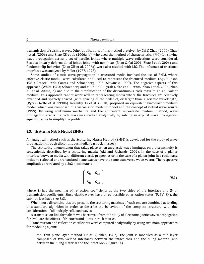
amplitudes are related by a 2x2 block matrix
where SSSSii has the meaning of reflection coefficients at the two sides of the interface and SSSSij of
transmission coefficients. Since elastic waves have three possible polarization states (P, SV, SH), the
submatrices have size 3x3.
When more discontinuities are present, the scattering matrices of each one are combined according
to a standard algorithm in order to describe the behaviour of the complete structure, with due
consideration of all multiply reflected waves.
A transmission line formalism was borrowed from the study of electromagnetic waves propagation for evaluate the effects of fractures and joints in rock masses.
Transmission and reflection coefficients were computed analytically by using two main approaches for modelling a joint:
1. the “thin plane layer method TPLM” (Fehler, 1982): the joint is modelled as a thin layer
composed of two welded interfaces between the intact rock and the filling material and
between the filling material and the intact rock (Figure 1a).
SSSS11 11 11 11 SSSS12121212
SSSS21 21 21 21 SSSS22222222
(0.1)
Thesis summary 7
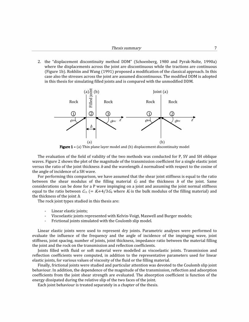
2. the “displacement discontinuity method DDM” (Schoenberg, 1980 and Pyrak-Nolte, 1990a)
where the displacements across the joint are discontinuous while the tractions are continuous
(Figure 1b). Rokhlin and Wang (1991) proposed a modification of the classical approach. In this
case also the stresses across the joint are assumed discontinuous. The modified DDM is adopted
in this thesis for simulating filled joints and is compared with the unmodified DDM.
(a) (b)
Figure Figure Figure Figure 1111 –––– (a) Thin plane layer model and (b) displacement discontinuity model
The evaluation of the field of validity of the two methods was conducted for P, SV and SH oblique
waves. Figure 2 shows the plot of the magnitude of the transmission coefficient for a single elastic joint
versus the ratio of the joint thickness h and the wavelength λ normalised with respect to the cosine of
the angle of incidence of a SH wave.
For performing this comparison, we have assumed that the shear joint stiffness is equal to the ratio
between the shear modulus of the filling material Gf and the thickness h of the joint. Same
considerations can be done for a P wave impinging on a joint and assuming the joint normal stiffness
equal to the ratio between C11 (= Kf+4/3Gf, where Kf is the bulk modulus of the filling material) and
the thickness of the joint h.
The rock joint types studied in this thesis are:
- Linear elastic joints;
- Viscoelastic joints represented with Kelvin-Voigt, Maxwell and Burger models;
- Frictional joints simulated with the Coulomb slip model.
Linear elastic joints were used to represent dry joints. Parametric analyses were performed to
evaluate the influence of the frequency and the angle of incidence of the impinging wave, joint
stiffness, joint spacing, number of joints, joint thickness, impedance ratio between the material filling the joint and the rock on the transmission and reflection coefficients.
Joints filled with fluid or soft material were modelled as viscoelastic joints. Transmission and reflection coefficients were computed, in addition to the representative parameters used for linear
elastic joints, for various values of viscosity of the fluid or the filling material.
Finally, frictional joints were studied and particular attention was devoted to the Coulomb slip joint
behaviour. In addition, the dependence of the magnitude of the transmission, reflection and adsorption
coefficients from the joint shear strength are evaluated. The absorption coefficient is function of the
energy dissipated during the relative slip of the two faces of the joint.
Each joint behaviour is treated separately in a chapter of the thesis.
Fil
led
jo
int
(a) (b)
z
Rock
h
2
1
1
1
Rock
3
1
ϑinc ϑinc
Joint (a)
(a)
z
Rock
1
1
Rock
2
1
ϑinc ϑinc


Thesis summary 9
(a)
(b)
Figure Figure Figure Figure 4444 –––– (a) Finite element model ad (b) equivalent electric circuit
Experimental tests presented by Li & Ma (2009) and conducted on the modified split Hopkinson
pressure bar (SHPB) (Figure 5) are also back analysed. The tests were executed on a granite bar with
in the middle a joint filled with sand with a water content of 5%. The spectrum of the measured
transmitted wave was fitted with elastic and viscoelastic models to evaluate the model that represents better the joint investigated.
Figure Figure Figure Figure 5555 –––– Schematic of modified split Hopkinson pressure bar (SHPB) (Li & Ma, 2009)
3.5.3.5.3.5.3.5. Wave propagation through periodic rock jointsWave propagation through periodic rock jointsWave propagation through periodic rock jointsWave propagation through periodic rock joints
In this section, the effects on wave propagation of a set of periodic discontinuities are analysed. Wave propagation through N discontinuities is a complex problem if it is studied by the plane wave method
because of the multiple reflections between the discontinuities.
To address more easily this problem, we have adopted an approach used in the field of microwave
circuits, based on the concept of Bloch waves, i.e. elementary waves characterized by simple
propagation laws in periodic structures. Bloch waves are special combinations of forward and
backward waves that in the propagation from the input to the output plane of the periodic cell remain
unchanged, apart from a phase-shift, hence a time delay if this phase-shift is real or an attenuation if it is imaginary.
Bloch waves are not scattered at the cell boundaries, but are reflected from the interfaces between the periodic structure and the homogeneous half-spaces. In conclusion plane waves are basic wave
types in homogeneous media, while Bloch waves are the basic ones in periodic structures.
∆z
Z∞=cp=ρVP
F=ejωt
cell 1 cell i cell n
10 Thesis summary
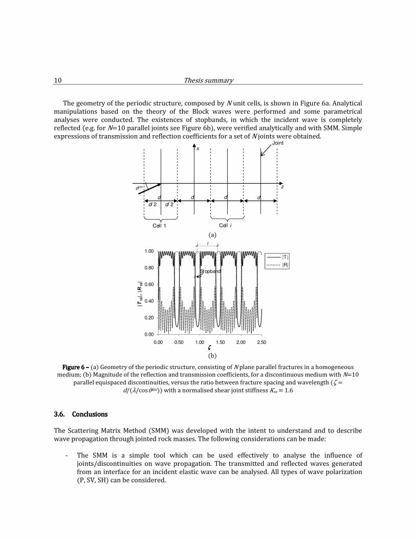
The geometry of the periodic structure, composed by N unit cells, is shown in Figure 6a. Analytical
manipulations based on the theory of the Block waves were performed and some parametrical
analyses were conducted. The existences of stopbands, in which the incident wave is completely
reflected (e.g. for N=10 parallel joints see Figure 6b), were verified analytically and with SMM. Simple
expressions of transmission and reflection coefficients for a set of N joints were obtained.
(a)
(b)
Figure Figure Figure Figure 6666 –––– (a) Geometry of the periodic structure, consisting of N plane parallel fractures in a homogeneous
medium; (b) Magnitude of the reflection and transmission coefficients, for a discontinuous medium with N=10
parallel equispaced discontinuities, versus the ratio between fracture spacing and wavelength (ζ =
d/(λ/cosϑinc)) with a normalised shear joint stiffness Kss = 1.6
3.6.3.6.3.6.3.6. ConclusionsConclusionsConclusionsConclusions
The Scattering Matrix Method (SMM) was developed with the intent to understand and to describe
wave propagation through jointed rock masses. The following considerations can be made:
- The SMM is a simple tool which can be used effectively to analyse the influence of
joints/discontinuities on wave propagation. The transmitted and reflected waves generated
from an interface for an incident elastic wave can be analysed. All types of wave polarization
(P, SV, SH) can be considered.
Joint x
d/ 2 d/ 2
ϑinc z
d
Cell 1
d d
Cell i
d
0.00
0.20
0.40
0.60
0.80
1.00
0.00 0.50 1.00 1.50 2.00 2.50
|T1
0|,
|R
10|
ζζζζ
|T |
|R|
l
Stopband
Thesis summary 11
- SMM operates in frequency domain but can be also applied to transient waves (after FFT). This
was proven to be true by comparing the SMM with numerical methods such as DEM and the
Method of Characteristics.
- The displacement discontinuity method (DDM) and the thin plate layer method (TPLM) were
shown to model satisfactorily a joint only when its thickness d is much smaller than the
wavelength λ (d / λ < 0.1).
- Linear elastic, viscoelastic and Coulomb slip models were implemented successfully with the
SMM in order to simulate dry, fluid or soft material filled and frictional joints. It was found that
the admittance or compliance of a joint is the most significant parameter that influences the
magnitude of the transmission and reflection coefficients.
- The Kelvin, Maxwell and Burger models, based on the modified split Hopkinson pressure bar
(SHPB) tests and curve fitting, were found to describe satisfactorily the seismic response of
viscoelastic joints filled with sand for P-wave incidence. In particular, the viscoelastic Burger
method is the model that represents better the filled joint tested. Moreover, it was verified
experimentally as the normal joint stiffness can be estimated as the ratio between C11 of the
filling material and the thickness of the joint.
- When a periodic spatial distribution of joints is considered, the Bloch waves were found to be
particularly appropriate for studying the wave propagation phenomenon. Simple expressions
of the transmission and reflection coefficients for N joints were derived. We have verified that
for some values of joint spacing ratio (ratio between the joint spacing and the wavelength) the incident wave is completely reflected. These zones are called stopbands.
- Transmitted and reflected waves are significantly affected by the frequency content, angle of
incidence, stiffness, viscosity, thickness, number and spacing of the joints. The filled joints response is also influenced by the impedance ratio between filling material and rock.
- The amplitude of the transmitted wave increases with the increasing of the joint stiffness and
decreases with the increasing of the frequency, the number of joints and the joint thickness.
The transmission coefficient becomes essentially independent from the number of joints when the ratio between the joint spacing and the wavelength is small.
- The effects of frictional joints on wave propagation were investigated. The Coulomb slip model
was implemented to simulate the joint behaviour when non linear deformations are mobilised. The shear strength of the joint is the quantity that governs this problem. In fact, the
transmission coefficient decreases with the increasing of the joint shear stress ratio. This is the ratio between the maximum of the incident shear stress wave and the shear strength.
- When slip occurs part of the incident energy is dissipated. This dissipation is evaluated with an
absorption coefficient that increases rapidly for low values of the shear stress ratio and tends
to a constant value for large ones. Some considerations on the influence of the number of joints and the joint spacing on the transmission and reflection coefficients were given.
- We have proven analytically, by using an equivalent transmission line circuit and after the
Maxwell analogy between electrical and mechanical quantities, that the element size of 1/8λ of
12 Thesis summary
the mesh of the numerical model, prescribed by Kuhlemeyer & Lysmer (1973), can be used to
model correctly the wave propagation across the mesh. In this case the error is assessed to be
approximately 8%. Obviously lower values produce smaller errors in wave propagation
modelling.
- With a comparative study with the SMM, the DEM codes such as UDEC and 3DEC are found to
simulate accurately the wave propagation phenomena in rock masses. Some additional difficulties are experienced in the modelling of an oblique incident wave.
4.4.4.4. Laboratory testingLaboratory testingLaboratory testingLaboratory testing
4.1.4.1.4.1.4.1. IntroductionIntroductionIntroductionIntroduction
Laboratory tests were carried out with the Resonant Column Apparatus (RCA), a testing equipment
usually adopted for soil dynamic testing.
In this part of the thesis, particular attention is given to the estimation of the shear modulus at
small strains and the damping ratio of rock material. Also, rock specimens which contain artificial
joints with either smooth or rough surfaces are considered. Three-dimensional analyses with the
Discrete Element Method (DEM) were performed to evaluate the reliability of the experimental results
obtained.
The group velocity dispersion, occurring when a wave crosses a fracture or a set of fractures, was
thus investigated by means of both the RCA tests and DEM analyses. Measured and computed transfer
functions were compared for all the specimens tested and considerations about the material damping
ratio were derived.
A correction procedure was developed to allow for the correct estimate of the dynamic properties
of the rock tested. Correction factors were obtained by performing DEM analyses on aluminium
specimens. These allow to reduce of about five times the error in the estimation of the shear modulus
at small strains which was obtained from RCA testing.
The group wave velocity reduction, due to the presence of the fractures, as obtained from
laboratory tests, was also analysed by the scattering matrix method.
4.2.4.2.4.2.4.2. Previous workPrevious workPrevious workPrevious work
The use of the RCA for testing rock specimen is very little treated in literature. Among the few
contributions, Xiaoming et al. (2006) present an application of this apparatus on intact rock specimens.
On the other hand, several examples of experimental studies on intact and fractured specimens were performed with ultrasonic and Hopkinson pressure bar tests. Some examples are those
presented by Pyrak-Nolte et al. (1987, 1990a, 1990b), Boadu & Long (1996), Leucci (2006), Li & Ma
(2009).
Thesis summary 13
4.3.4.3.4.3.4.3. Use of the Resonant Column Apparatus for wave propagation studiesUse of the Resonant Column Apparatus for wave propagation studiesUse of the Resonant Column Apparatus for wave propagation studiesUse of the Resonant Column Apparatus for wave propagation studies
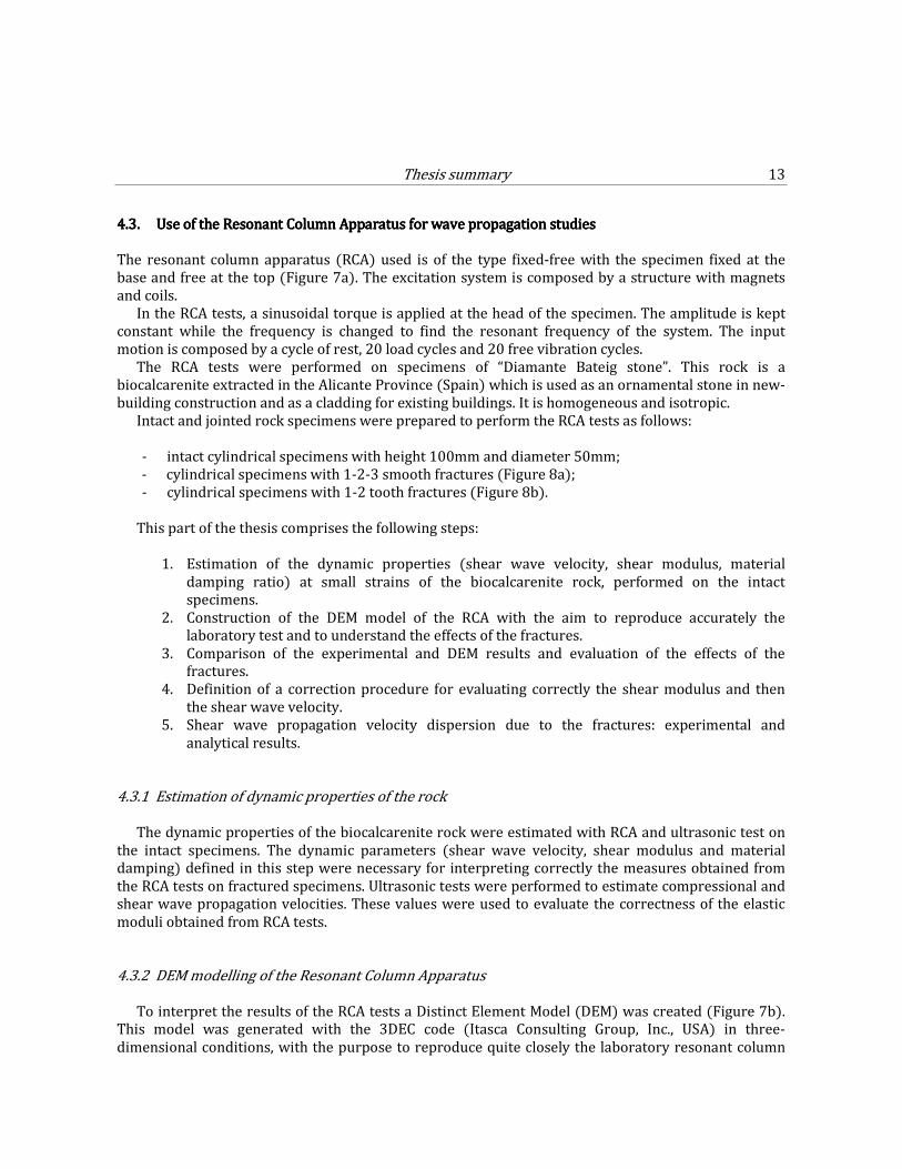
The resonant column apparatus (RCA) used is of the type fixed-free with the specimen fixed at the
base and free at the top (Figure 7a). The excitation system is composed by a structure with magnets
and coils.
In the RCA tests, a sinusoidal torque is applied at the head of the specimen. The amplitude is kept
constant while the frequency is changed to find the resonant frequency of the system. The input
motion is composed by a cycle of rest, 20 load cycles and 20 free vibration cycles.
The RCA tests were performed on specimens of “Diamante Bateig stone”. This rock is a
biocalcarenite extracted in the Alicante Province (Spain) which is used as an ornamental stone in new-
building construction and as a cladding for existing buildings. It is homogeneous and isotropic.
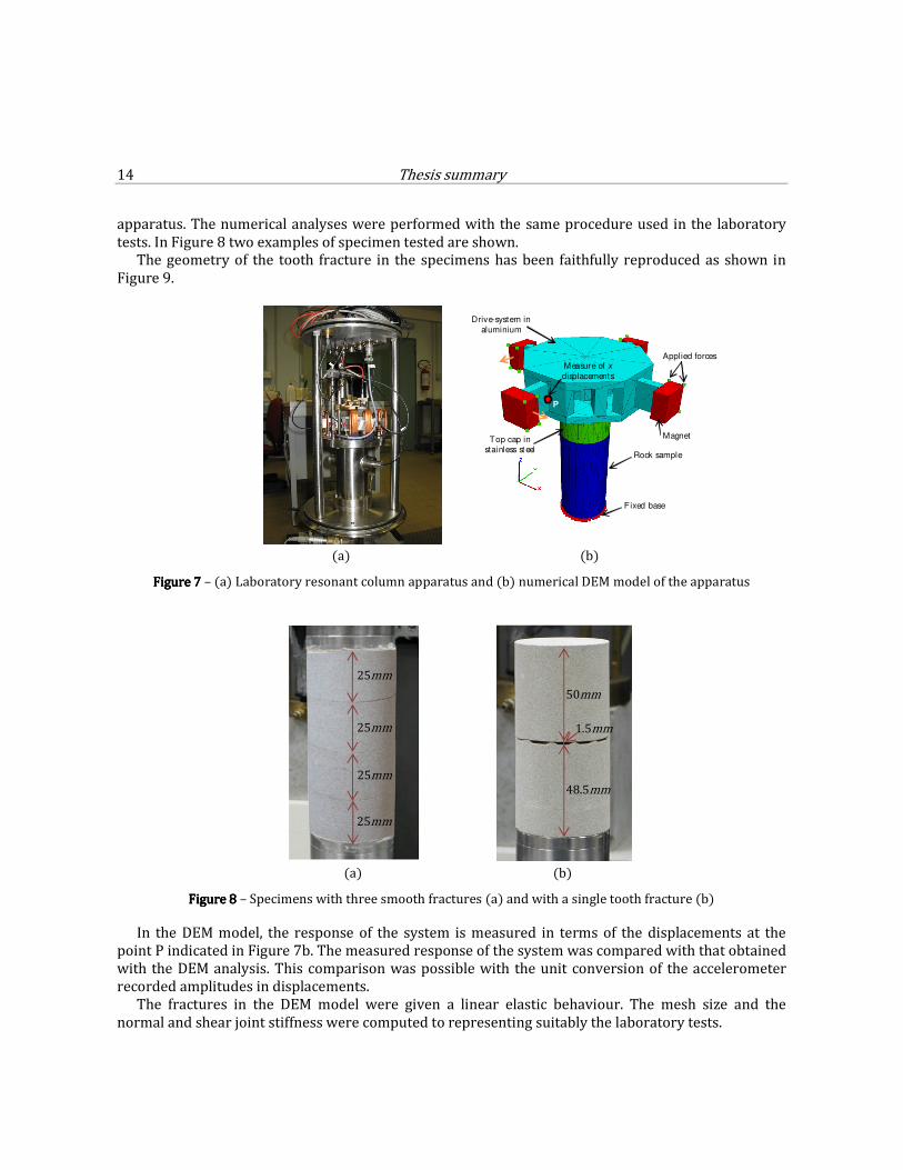
Intact and jointed rock specimens were prepared to perform the RCA tests as follows:
- intact cylindrical specimens with height 100mm and diameter 50mm;
- cylindrical specimens with 1-2-3 smooth fractures (Figure 8a);
- cylindrical specimens with 1-2 tooth fractures (Figure 8b).
This part of the thesis comprises the following steps:
1. Estimation of the dynamic properties (shear wave velocity, shear modulus, material
damping ratio) at small strains of the biocalcarenite rock, performed on the intact specimens.
2. Construction of the DEM model of the RCA with the aim to reproduce accurately the laboratory test and to understand the effects of the fractures.
3. Comparison of the experimental and DEM results and evaluation of the effects of the fractures.
4. Definition of a correction procedure for evaluating correctly the shear modulus and then
the shear wave velocity.
5. Shear wave propagation velocity dispersion due to the fractures: experimental and
analytical results.
4.3.1 Estimation of dynamic properties of the rock
The dynamic properties of the biocalcarenite rock were estimated with RCA and ultrasonic test on
the intact specimens. The dynamic parameters (shear wave velocity, shear modulus and material damping) defined in this step were necessary for interpreting correctly the measures obtained from
the RCA tests on fractured specimens. Ultrasonic tests were performed to estimate compressional and shear wave propagation velocities. These values were used to evaluate the correctness of the elastic
moduli obtained from RCA tests.
4.3.2 DEM modelling of the Resonant Column Apparatus
To interpret the results of the RCA tests a Distinct Element Model (DEM) was created (Figure 7b). This model was generated with the 3DEC code (Itasca Consulting Group, Inc., USA) in three-
dimensional conditions, with the purpose to reproduce quite closely the laboratory resonant column
14 Thesis summary
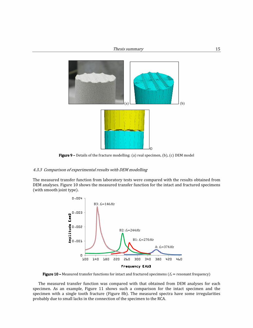
apparatus. The numerical analyses were performed with the same procedure used in the laboratory
tests. In Figure 8 two examples of specimen tested are shown. The geometry of the tooth fracture in the specimens has been faithfully reproduced as shown in
Figure 9.
(a) (b)
Figure Figure Figure Figure 7777 – (a) Laboratory resonant column apparatus and (b) numerical DEM model of the apparatus
(a) (b)
Figure Figure Figure Figure 8888 – Specimens with three smooth fractures (a) and with a single tooth fracture (b)
In the DEM model, the response of the system is measured in terms of the displacements at the
point P indicated in Figure 7b. The measured response of the system was compared with that obtained
with the DEM analysis. This comparison was possible with the unit conversion of the accelerometer
recorded amplitudes in displacements.
The fractures in the DEM model were given a linear elastic behaviour. The mesh size and the
normal and shear joint stiffness were computed to representing suitably the laboratory tests.
P
Applied forces
Drive-system in
aluminium
Top cap in stainless st eel
F ixed base
Rock sample
Measure of x
displacements
Magnet
50mm
48.5mm
1.5mm
25mm
25mm
25mm
25mm
Thesis summary 15
(a) (b)
©
Figure Figure Figure Figure 9999 –––– Details of the fracture modelling: (a) real specimen, (b), (c) DEM model
4.3.3 Comparison of experimental results with DEM modelling
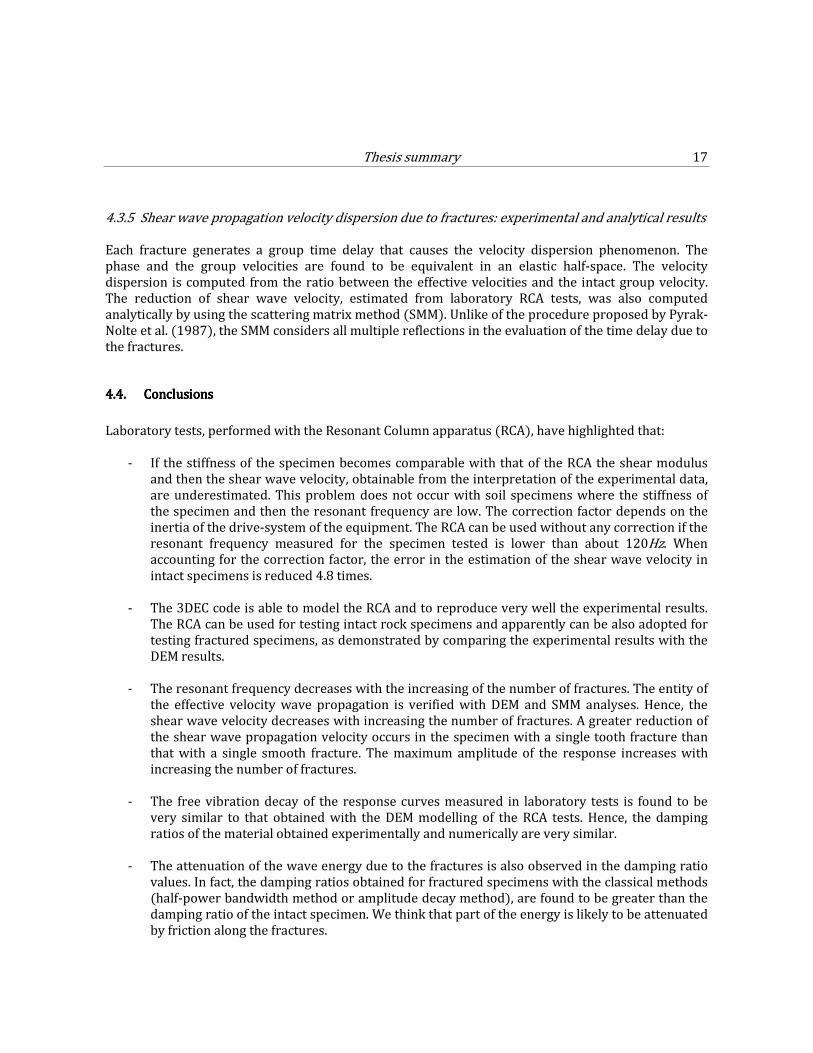
The measured transfer function from laboratory tests were compared with the results obtained from
DEM analyses. Figure 10 shows the measured transfer function for the intact and fractured specimens
(with smooth joint type).
Figure Figure Figure Figure 10101010 –––– Measured transfer functions for intact and fractured specimens (fn = resonant frequency)
The measured transfer function was compared with that obtained from DEM analyses for each
specimen. As an example, Figure 11 shows such a comparison for the intact specimen and the specimen with a single tooth fracture (Figure 8b). The measured spectra have some irregularities
probably due to small lacks in the connection of the specimen to the RCA.
0
0,001
0,002
0,003
0,004
100 140 180 220 260 300 340 380 420 460
Amplitude [
Amplitude [
Amplitude [
Amplitude [mm
mm
mmmm]] ]]
Frequency [Frequency [Frequency [Frequency [HzHzHzHz]]]]
A: fn=374Hz
B1: fn=270Hz
B2: fn=244Hz
B3: fn=146Hz

16 Thesis summary
(a) (b)
Figure Figure Figure Figure 11111111 – Measured and numerical transfer function for intact specimen (a) and for the specimen with a single
tooth fracture (b)
4.3.4 Correction of the results
A correction procedure was implemented to account for the fact that in the resonant column tests the
shear modulus of stiff specimens is underestimated. Xiaoming et al. (2006) also proved this statement
for intact specimen.
The correction procedure is based on the definition of a correction factor Q of the shear modulus
obtained from the standard procedure of interpretation of the RCA tests. This factor was computed by performing a series of DEM analyses on 8 aluminum cylindrical hollow specimens with different cross
section area and then with different stiffness. These DEM models are initially calibrated from the RCA results obtained by testing the first Qluminium specimen (P1) used in DEM analyses (Figure 12).
(a) (b)
Figure Figure Figure Figure 12121212 – (a) Aluminium specimen P1 and (b) 3DEC model of the resonant column with the aluminium
specimen
0,0E+00
1,0E-04
2,0E-04
3,0E-04
4,0E-04
5,0E-04
290 330 370 410 450
Amplitude [
Amplitude [
Amplitude [
Amplitude [mm
mm
mmmm]] ]]
Frequency [Frequency [Frequency [Frequency [HzHzHzHz]]]]
MeasuredFitting
0,0E+00
5,0E-04
1,0E-03
1,5E-03
2,0E-03
2,5E-03
115 155 195 235 275Amplitude [
Amplitude [
Amplitude [
Amplitude [mm
mm
mmmm]] ]]
Frequency [Frequency [Frequency [Frequency [HzHzHzHz]]]]
MeasuredFitting
Thesis summary 17
4.3.5 Shear wave propagation velocity dispersion due to fractures: experimental and analytical results
Each fracture generates a group time delay that causes the velocity dispersion phenomenon. The
phase and the group velocities are found to be equivalent in an elastic half-space. The velocity
dispersion is computed from the ratio between the effective velocities and the intact group velocity.
The reduction of shear wave velocity, estimated from laboratory RCA tests, was also computed
analytically by using the scattering matrix method (SMM). Unlike of the procedure proposed by Pyrak-
Nolte et al. (1987), the SMM considers all multiple reflections in the evaluation of the time delay due to
the fractures.
4.4.4.4.4.4.4.4. ConclusionsConclusionsConclusionsConclusions
Laboratory tests, performed with the Resonant Column apparatus (RCA), have highlighted that:
- If the stiffness of the specimen becomes comparable with that of the RCA the shear modulus
and then the shear wave velocity, obtainable from the interpretation of the experimental data,
are underestimated. This problem does not occur with soil specimens where the stiffness of
the specimen and then the resonant frequency are low. The correction factor depends on the
inertia of the drive-system of the equipment. The RCA can be used without any correction if the
resonant frequency measured for the specimen tested is lower than about 120Hz. When accounting for the correction factor, the error in the estimation of the shear wave velocity in
intact specimens is reduced 4.8 times.
- The 3DEC code is able to model the RCA and to reproduce very well the experimental results.
The RCA can be used for testing intact rock specimens and apparently can be also adopted for
testing fractured specimens, as demonstrated by comparing the experimental results with the
DEM results.
- The resonant frequency decreases with the increasing of the number of fractures. The entity of
the effective velocity wave propagation is verified with DEM and SMM analyses. Hence, the
shear wave velocity decreases with increasing the number of fractures. A greater reduction of
the shear wave propagation velocity occurs in the specimen with a single tooth fracture than
that with a single smooth fracture. The maximum amplitude of the response increases with
increasing the number of fractures.
- The free vibration decay of the response curves measured in laboratory tests is found to be
very similar to that obtained with the DEM modelling of the RCA tests. Hence, the damping
ratios of the material obtained experimentally and numerically are very similar.
- The attenuation of the wave energy due to the fractures is also observed in the damping ratio
values. In fact, the damping ratios obtained for fractured specimens with the classical methods
(half-power bandwidth method or amplitude decay method), are found to be greater than the
damping ratio of the intact specimen. We think that part of the energy is likely to be attenuated
by friction along the fractures.

18 Thesis summary
- We have proven that the specimen is not completely loaded by torsional excitation when the
resonant frequency of a fractured specimen becomes greater than that of an intact one. In
these conditions the fractured specimen cannot be tested with the RCA.
5.5.5.5. DEM modelling of the Tel Beer Sheva cavernDEM modelling of the Tel Beer Sheva cavernDEM modelling of the Tel Beer Sheva cavernDEM modelling of the Tel Beer Sheva cavern
5.1.5.1.5.1.5.1. IntroductionIntroductionIntroductionIntroduction
The stability of large span caverns is an important problem in underground mining and civil
engineering works. In particular, the evaluation of the cavern roof collapse is very important to
guarantee safety and to avoid accidents.
In the final part of this thesis, the stress wave interaction with underground structures and the implications on their stability was considered in detail by using the DEM modelling in two and in three
dimensional conditions. In particular, the water storage cavern, located at Tel Beer Sheva
archaeological site in Israel, was investigated by using 2D and 3D numerical models. Static and
dynamic analyses were performed to evaluate the stability at the present configuration of the cavern.
Preliminary dynamic analyses were intended to study the dependence of the damage level on the
amplitude, duration, frequency and direction of the seismic motion in both horizontal and vertical
directions. Finally, two and three-dimensional analyses were performed to evaluate the stability of the
cavern in its present configuration with the application of the horizontal and vertical deconvoluted
components of the Nuweiba earthquake (1995).
5.2.5.2.5.2.5.2. Previous workPrevious workPrevious workPrevious work
Few studies of the stability of large span caverns were published. Barton et al. (1994) presented the
stability analysis, with UDEC code, of the Olympic Ice Hockey cavern at Gjøvik, Norway. This underground opening has a span of 62 m and a cover of about 25 m and is located in a rock mass with
high horizontal stresses. Bakun-Mazor et al. (2009) studied the mechanical layering effects on stability
of underground openings in jointed sedimentary rocks with the discontinuous deformation analysis (DDA) method. Various contributions on the analysis of stability of horizontal bedded and vertically
jointed roofs were given by using the theory of the Voussoir beam (e.g. Beer & Meek (1982), Hatzor & Benary (1998)).
5.3.5.3.5.3.5.3. Description of the case studyDescription of the case studyDescription of the case studyDescription of the case study The water storage cavern is located in the archaeological site (Iron age 1200-700 bc) of Tell Beer Sheva in Israel. The archaeological site rises at 3km East of the modern city of Beer Sheva near the
communities of Tel Sheva and Omer, in Israel. The water system, dated to 1000 BC, was established as
part of the city's fortifications. It consists of three components: a shaft 17m deep, lined with stones with a flight of steps along its sides; a reservoir divided into five spaces, with a total capacity of about
700m3; and a winding feeder channel that led flood waters from the spring into the reservoir. A schematic representation of the archaeological site and the under-lying water reservoir are shown in
Figure 13a. The real excavation sequence of the water storage cavern is unknown. However, modern
excavation of the underground water system revealed that the roof had collapsed, probably during the
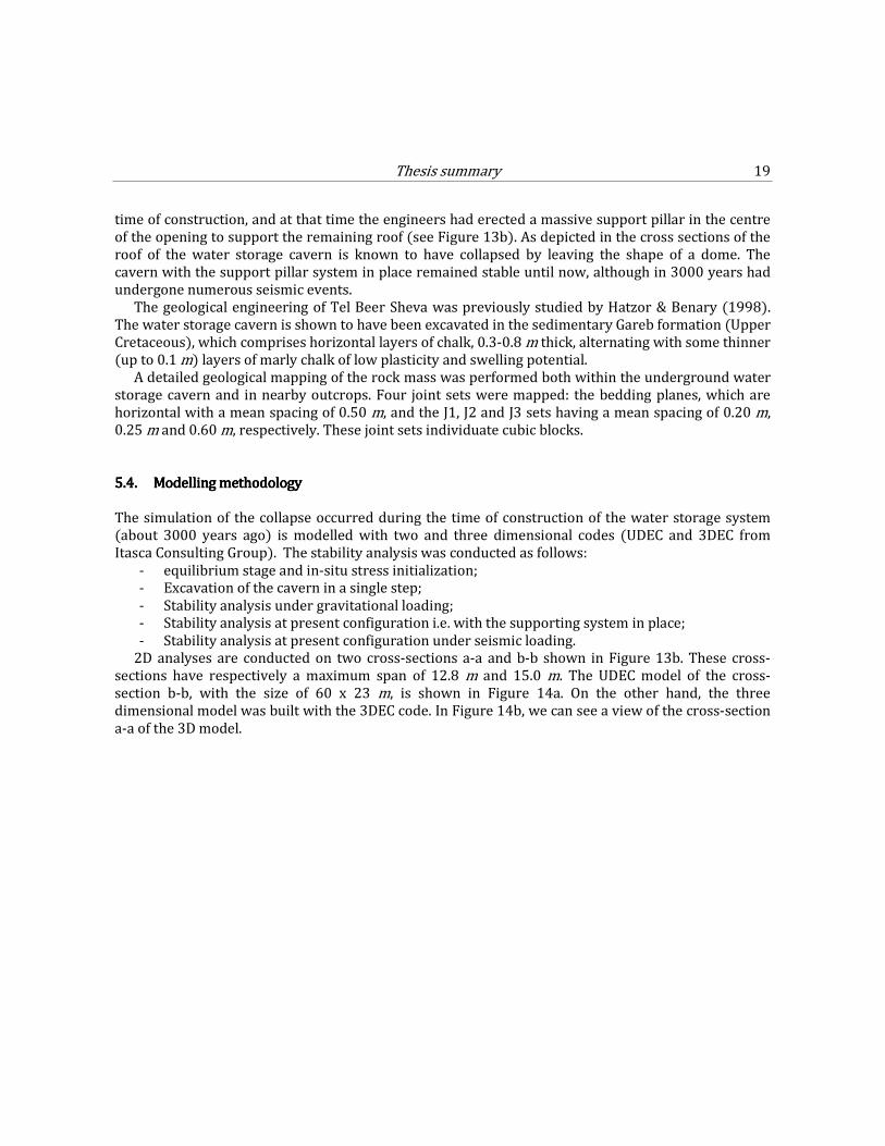
Thesis summary 19
time of construction, and at that time the engineers had erected a massive support pillar in the centre
of the opening to support the remaining roof (see Figure 13b). As depicted in the cross sections of the
roof of the water storage cavern is known to have collapsed by leaving the shape of a dome. The
cavern with the support pillar system in place remained stable until now, although in 3000 years had
undergone numerous seismic events.
The geological engineering of Tel Beer Sheva was previously studied by Hatzor & Benary (1998).
The water storage cavern is shown to have been excavated in the sedimentary Gareb formation (Upper
Cretaceous), which comprises horizontal layers of chalk, 0.3-0.8 m thick, alternating with some thinner
(up to 0.1 m) layers of marly chalk of low plasticity and swelling potential.
A detailed geological mapping of the rock mass was performed both within the underground water
storage cavern and in nearby outcrops. Four joint sets were mapped: the bedding planes, which are
horizontal with a mean spacing of 0.50 m, and the J1, J2 and J3 sets having a mean spacing of 0.20 m,
0.25 m and 0.60 m, respectively. These joint sets individuate cubic blocks.
5.4.5.4.5.4.5.4. Modelling methodologyModelling methodologyModelling methodologyModelling methodology
The simulation of the collapse occurred during the time of construction of the water storage system
(about 3000 years ago) is modelled with two and three dimensional codes (UDEC and 3DEC from
Itasca Consulting Group). The stability analysis was conducted as follows:
- equilibrium stage and in-situ stress initialization; - Excavation of the cavern in a single step;
- Stability analysis under gravitational loading; - Stability analysis at present configuration i.e. with the supporting system in place;
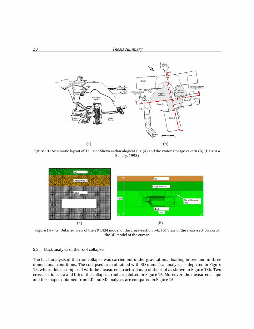
- Stability analysis at present configuration under seismic loading. 2D analyses are conducted on two cross-sections a-a and b-b shown in Figure 13b. These cross-
sections have respectively a maximum span of 12.8 m and 15.0 m. The UDEC model of the cross-
section b-b, with the size of 60 x 23 m, is shown in Figure 14a. On the other hand, the three
dimensional model was built with the 3DEC code. In Figure 14b, we can see a view of the cross-section
a-a of the 3D model.
20 Thesis summary
(a) (b)
Figure Figure Figure Figure 13131313 - Schematic layout of Tel Beer Sheva archaeological site (a) and the water storage cavern (b) (Hatzor &
Benary, 1998)
(a) (b)
Figure Figure Figure Figure 14141414 – (a) Detailed view of the 2D DEM model of the cross-section b-b; (b) View of the cross-section a-a of
the 3D model of the cavern
5.5.5.5.5.5.5.5. Back analysis of the roof collapseBack analysis of the roof collapseBack analysis of the roof collapseBack analysis of the roof collapse
The back analysis of the roof collapse was carried out under gravitational loading in two and in three
dimensional conditions. The collapsed area obtained with 3D numerical analyses is depicted in Figure
15, where this is compared with the measured structural map of the roof as shown in Figure 13b. Two cross sections a-a and b-b of the collapsed roof are plotted in Figure 16. Moreover, the measured shape
and the shapes obtained from 2D and 3D analyses are compared in Figure 16.

Thesis summary 21
Figure Figure Figure Figure 15151515 - View of the roof of the cavern with support system activated – Plot of vertical displacements
magnitude and comparison of the collapsed area with the measured structural map of the roof showed in Figure
13b
(a)
(b)
Figure Figure Figure Figure 16161616 - Plots of vertical displacements magnitude and comparison of the collapsed zone, obtained with 3D
analyses, with the measured structural roof and with UDEC roof shape for the cross-section a-a (a) and cross-
section b-b (b)
Particular attention was devoted to the evaluation of the influence of the stress ratio K0 on the
stability of the cavern. The arching effect in 2D conditions and the dome effect in 3D conditions were described and shown. The importance of the 3D modelling was proved by comparing the results with
those obtained with 2D analyses.
22 Thesis summary
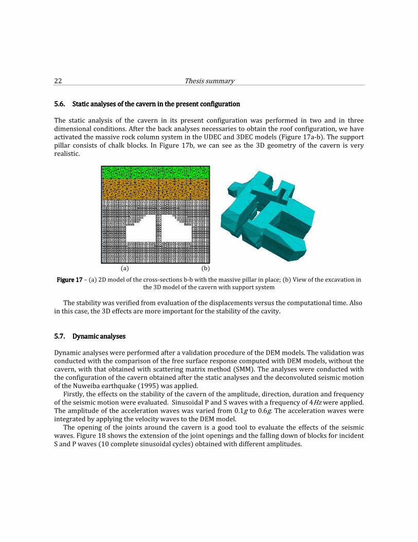
5.6.5.6.5.6.5.6. Static analyses ofStatic analyses ofStatic analyses ofStatic analyses of the cavern the cavern the cavern the cavern in thein thein thein the present configurationpresent configurationpresent configurationpresent configuration
The static analysis of the cavern in its present configuration was performed in two and in three
dimensional conditions. After the back analyses necessaries to obtain the roof configuration, we have activated the massive rock column system in the UDEC and 3DEC models (Figure 17a-b). The support
pillar consists of chalk blocks. In Figure 17b, we can see as the 3D geometry of the cavern is very realistic.
(a) (b)
Figure Figure Figure Figure 17171717 – (a) 2D model of the cross-sections b-b with the massive pillar in place; (b) View of the excavation in
the 3D model of the cavern with support system
The stability was verified from evaluation of the displacements versus the computational time. Also
in this case, the 3D effects are more important for the stability of the cavity.
5.7.5.7.5.7.5.7. DynamiDynamiDynamiDynamic analysesc analysesc analysesc analyses
Dynamic analyses were performed after a validation procedure of the DEM models. The validation was conducted with the comparison of the free surface response computed with DEM models, without the
cavern, with that obtained with scattering matrix method (SMM). The analyses were conducted with
the configuration of the cavern obtained after the static analyses and the deconvoluted seismic motion
of the Nuweiba earthquake (1995) was applied.
Firstly, the effects on the stability of the cavern of the amplitude, direction, duration and frequency
of the seismic motion were evaluated. Sinusoidal P and S waves with a frequency of 4Hz were applied.
The amplitude of the acceleration waves was varied from 0.1g to 0.6g. The acceleration waves were
integrated by applying the velocity waves to the DEM model.
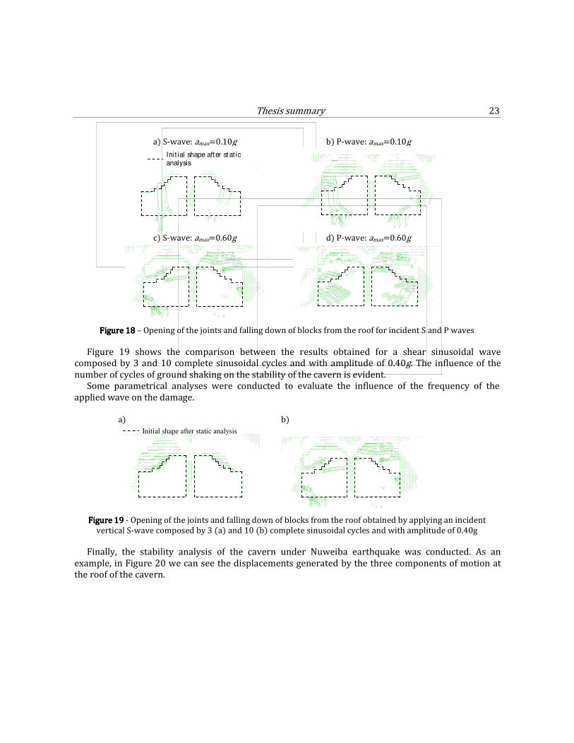
The opening of the joints around the cavern is a good tool to evaluate the effects of the seismic waves. Figure 18 shows the extension of the joint openings and the falling down of blocks for incident
S and P waves (10 complete sinusoidal cycles) obtained with different amplitudes.
Thesis summary 23
a) S-wave: amax=0.10g b) P-wave: amax=0.10g
c) S-wave: amax=0.60g d) P-wave: amax=0.60g
Figure Figure Figure Figure 18181818 – Opening of the joints and falling down of blocks from the roof for incident S and P waves
Figure 19 shows the comparison between the results obtained for a shear sinusoidal wave composed by 3 and 10 complete sinusoidal cycles and with amplitude of 0.40g. The influence of the
number of cycles of ground shaking on the stability of the cavern is evident. Some parametrical analyses were conducted to evaluate the influence of the frequency of the
applied wave on the damage.
a) b)
Figure Figure Figure Figure 19191919 - Opening of the joints and falling down of blocks from the roof obtained by applying an incident
vertical S-wave composed by 3 (a) and 10 (b) complete sinusoidal cycles and with amplitude of 0.40g
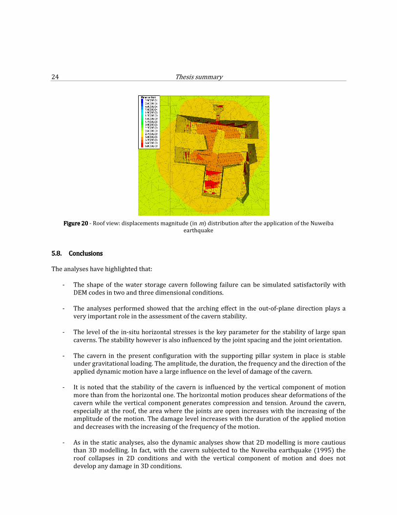
Finally, the stability analysis of the cavern under Nuweiba earthquake was conducted. As an
example, in Figure 20 we can see the displacements generated by the three components of motion at the roof of the cavern.
Init ial shape after stat ic analysis
Initial shape after static analysis
24 Thesis summary
Figure Figure Figure Figure 20202020 - Roof view: displacements magnitude (in m) distribution after the application of the Nuweiba
earthquake
5.8.5.8.5.8.5.8. ConclusionsConclusionsConclusionsConclusions
The analyses have highlighted that:
- The shape of the water storage cavern following failure can be simulated satisfactorily with
DEM codes in two and three dimensional conditions.
- The analyses performed showed that the arching effect in the out-of-plane direction plays a
very important role in the assessment of the cavern stability.
- The level of the in-situ horizontal stresses is the key parameter for the stability of large span
caverns. The stability however is also influenced by the joint spacing and the joint orientation.
- The cavern in the present configuration with the supporting pillar system in place is stable under gravitational loading. The amplitude, the duration, the frequency and the direction of the
applied dynamic motion have a large influence on the level of damage of the cavern.
- It is noted that the stability of the cavern is influenced by the vertical component of motion
more than from the horizontal one. The horizontal motion produces shear deformations of the
cavern while the vertical component generates compression and tension. Around the cavern,
especially at the roof, the area where the joints are open increases with the increasing of the amplitude of the motion. The damage level increases with the duration of the applied motion
and decreases with the increasing of the frequency of the motion.
- As in the static analyses, also the dynamic analyses show that 2D modelling is more cautious than 3D modelling. In fact, with the cavern subjected to the Nuweiba earthquake (1995) the
roof collapses in 2D conditions and with the vertical component of motion and does not develop any damage in 3D conditions.

Thesis summary 25
- The dynamic analyses, performed in this thesis, show indeed that the vertical component of the
earthquake motion needs more attention when performing design analyses for the assessment
of stability of underground structures.
6.6.6.6. RecommendRecommendRecommendRecommendations for further developmentsations for further developmentsations for further developmentsations for further developments
Further developments are needed as some open questions remain to be addressed for the study of wave propagation in rock masses and their effects on the stability of geotechnical structures. The
following points are raised:
- Extension of the SMM to other more complex joint models. Evaluation of the effects on wave propagation of the presence of two joint sets mutually perpendicular or nearly perpendicular.
- Additional resonant column tests to be carried out for other geometries of fractures. Definition
of the correction factors for the RCA by performing laboratory RCA tests on aluminium or steel
specimens.
- Additional 3D dynamic analyses to evaluate the effects of the seismic motion on the Tel Beer
Sheva cavern.
- Extension of 3D analyses to other case studies to better evaluate the effects of the earthquake
especially on large underground openings. Hence, the definition of the link between the level of damage and the shape, the orientation of joints, the stress ratio, the frequency and the
amplitude of the motion.
- The study of possible reinforcement systems to improve the stability of caverns or
underground structures in general under dynamic loading.
7.7.7.7. Closure and Closure and Closure and Closure and practicalpracticalpracticalpractical implicationimplicationimplicationimplication
The thesis presents an extensive study of the effects of interfaces and discontinuities (e.g. rock joints)
developed with analytical, numerical and experimental analyses. In particular the analytical method
proposed is shown to be very effective for studying wave propagation problems in discontinuous
media. An innovative use of the resonant column apparatus is made, also based on a complex three
dimensional numerical modelling. Numerical analyses with Distinct Element Method in both 2D and
3D conditions highlight new significant aspects to evaluate the stress wave interaction with near surface underground structures, including their stability conditions.

26 Thesis summary
8.8.8.8. ReferencesReferencesReferencesReferences
Aki, K., Richards, P.G. (2002). “Quantitative seismology (2nd ed.)”. University Science Books, California.
Bakun-Mazor, D., Hatzor, Y.H., Dershowitz, W.S. (2009). “Modeling mechanical layering effects on
stability of underground openings in jointed sedimentary rocks”. International Journal of Rock
Mechanics & Mining Science, 46: 262-271.
Barton, N. By, T.L. Chryssanthakis, P. Tunbridge, L. Kristiansen, J. Løset, F. Bhasin, R.K. Westerdahl,
H. and Vik, G. (1994). “Predicted and measured performance of the 62 m span Norwegian olympic
ice Hockey Cavern at Gjøvik”. International Journal of Rock Mechanics and Mining Sciences &
Geomechanics, Vol. 31, Issue 6, pp: 617-641.
Beer G., Meek J.L. (1982). “Design curves for roofs and hanging-walls in bedded rock based on
“voussoir” beam and plate solutions”. Trans, Inst. Min. Metal, Vol. 91, pp. 18-22
Boadu, F.K. and Long, T.L., (1996). “Effects of fractures on seismic wave velocity and attenuation”.
Geophys. J. Int. 127, 86–110.
Cai, J.G., Zhao, J. (2000). “Effects of multiple parallel fractures on apparent wave attenuation in rock
masses”. Int J Rock Mech Min Sci 37:661–682.
Cook, N. G. W. (1992). “Natural fractures in rock: mechanical, hydraulic and seismic behaviour and
properties under normal stress”, International Journal of Rock Mechanics and Mining Sciences & Geomechanics Abstracts. Vol. 29(3), pp. 198-223.
Fehler, M. (1982). “Interaction of seismic waves with a viscous liquid layer”. Bulletin of Seismic
Association of America 72: 55-72.
Hatzor Y. H. and Benary R., (1998). “The Stability of a Laminated Voussoir Beam: Back Analysis of a
Historic Roof Collapse Using DDA”. Int. J. Rock Mech. Min. Sci. Vol. 35, No. 2, pp. 165-181.
Leucci, G. and De Giorgi, L. (2006). “Experimental studies on the effects of fracture on the P and S wave velocity propagation in sedimentary rock (“Calcarenite del Salento”)”, Engineering Geology 84, pp.
130–142.
Li, J. C. and Ma G. W. (2009). “Experimental study of stress wave propagation across a filled rock joint”, Int. J. Rock Mech. Min. Sci., 46(3), 471-478.
Li, J.C., Ma, G.W., Zhao, J. (2010). “An equivalent viscoelastic model for rock mass with parallel joints”. J
Geophys Res 115. doi: 10.1029/2008JB006241.
Miller, R.K. (1978). “The effects of boundary friction on the propagation of elastic waves”, Bulletin of
the Seismological Society of America, Vol. 68(4), pp. 987-998.
Miller, R.K. (1977). “An approximate method of analysis of the transmission of elastic waves through a frictional boundary”, Journal of Applied Mechanics, Vol. 44, pp. 652-656.

Thesis summary 27
Mindlin, R. D. (1960) “Waves and vibrations in isotropic, elastic plates, in Structural Mechanics”, edited
by J. N. Goodier and J . J. Hoff, pp. 199-232, Pergamon, New York, 1960.
Myer, L.R. Pyrak-Nolte, L.J., Cook, N.G.W. (1990), “Effects of single fractures on seismic wave
propagation”. Rock joints: 467-473. Barton, Stephansson. Balkema, Rotterdam.
Pyrak-Nolte, L.J, Myer, L.R. and Cook, N.G.W. (1990a). “Transmission of seismic waves across single
natural fractures”, Journal of Geophysical Research, Vol. 95(B6), pp. 86178638.
Pyrak-Nolte, L.J, Myer, L.R., and Cook, N.G.W. (1990b). “Anisotropy in seismic velocities and
amplitudes from multiple parallel fractures”, Journal of Geophysical Research, Vol. 95(B7), pp.
11345-11358.
Pyrak-Nolte, L.J. and Cook, N.G.W. (1987). “Elastic interface waves along a fracture”, Geophysical
Research Letters, Vol. 14(11), pp. 1107-1110.
Pyrak-Nolte, L.J. (1988). “Seismic Visibility of Fractures”, Ph.D. Thesis, University of California at
Berkeley, USA.
Schoenberg, M. (1980). “Elastic wave behaviour across linear slip interfaces”, Journal of Acoustics
Society of America, Vol. 68(5), pp. 1516-1521.
Xiaoming, Y. Jing, S. & Rui, S. (2006). “A modified approach for calculating dynamic shear modulus of stiff specimens by resonant column tests”. Earthquake Engineering and Engineering Vibration,
vol.5, No.1, pp 143-150.
Zhao, J. and Cai, J.G. (2001). “Transmission of elastic P-waves across single fractures with a nonlinear
normal deformational behavior”. Rock Mech Rock Eng 34:3-22.
Zhao, J., Zhao, X.B., Cai, J.G., Hefny A.M. (2006). “A further study on P-wave attenuation across parallel fractures with linear deformational behavior”. Int J Rock Mech Min Sci 43:776-788.
Zhao, X.B., Zhao, J., Cai, J.G. (2006a). “P-wave transmission across fractures with nonlinear
deformational behavior”. Int J. Numer Anal Methods Geomech 30:1097-1112.
Zhao, X.B., Zhao, J., Hefny, A.M., Cai, J.G. (2006b). “Normal transmission of S-wave across parallel fractures with coulomb slip behavior”. J Eng Mech 132:641-650.
9.9.9.9. List of publicationsList of publicationsList of publicationsList of publications
Perino, A., Lu, Q., Barla, G. (2011). “Analisi di stabilità di grandi cavità sotterranee con modellazione al
continuo e al discontinuo”. Incontro Annuale dei Ricercatori di Geotecnica 2011 - IARG 2011
Torino, 4-6 Luglio 2011, 4-6 Luglio 2011 , Torino (Italy).
Perino, A., Barla, G. (2011). “Propagazione ondosa in mezzi discontinui: metodi analitici e numerici”.
Incontro Annuale dei Ricercatori di Geotecnica 2011 - IARG 2011 Torino, 4-6 Luglio 2011, 4-6
Luglio 2011 , Torino (Italy).

28 Thesis summary
Zhu, J.B., Perino, A., Zhao, G.F., Barla, G., Li, J.C., Ma, G.W. and Zhao, J. (2011). “Seismic response of a
single and a set of filled joints of viscoelastic deformational behaviour”. Geophysical Journal
International, pp. 1315-1330. - ISSN 0956-540X.
Perino, A., Barla, G. (2011). “Wave propagation in jointed rock masses by analytical and distinct
element methods”. 13th International Conference of the International Association for Computer
Methods and Advances in Geomechanics, 09-11 maggio 2011, Melbourne (Australia).
Barla, G., Monacis, G., Perino, A., Hatzor, Y.H. (2010). “Distinct Element Modelling in Static and Dynamic
Conditions with Application to an Underground Archaeological Site”. Rock Mechanics And Rock
Engineering, vol. 43, pp. 877-890. - ISSN 0723-2632.
Perino, A., Zhu, J.B., Li, J.C., Barla, G., Zhao, J. (2010). “Theoretical Methods for Wave Propagation across
Jointed Rock Masses”. Rock Mechanics And Rock Engineering, vol. 43, pp. 799-809. - ISSN 0723-
2632.
Perino, A., Barla, G., Orta, R. (2010). “Wave propagation in discontinuous media”. In: Eurock 2010, 15-
18 June 2010, Lausanne.
Barla, G, Perino, A. (2009). “Pavoncelli Tunnel Case Study”. Rockeng09 - Rock Engineering In Difficult Conditions, 9 - 15 May 2009, Toronto.
Barla, G., Mensi, E., Perino, A (2008). “Analisi degli effetti sismici nelle gallerie profonde: la galleria
Pavoncelli dell'Acquedotto Pugliese”. Opere Geotecniche in Condizioni Sismiche. Pàtron editore, Bologna, pp. 383-412. ISBN 9788855530057.
Barla, G., Barla, M., Perino, A., Principito, M. (2008). “Soluzioni analitiche e numeriche nella
progettazione sismica delle opere in sotterraneo”. Opere geotecniche in condizioni sismiche /
G.Barla; M.Barla. Pàtron editore, Bologna, pp. 335-357. ISBN 9788855530057.
Recommended