WATER TREATMENTSYSTEMS AND EQUIPMENT
Place your industrial and commercialwater treatment needs in the hands
of a global leader.

WATER POTABILIZATION PLANT

FILTRATION AND POTABILIZATION Page
Page
Page
Page
Page
Page
Page
Page
Page
Page
Page
Page
Page
Page
Page
7
PRE-TREATMENTSOLUTIONS
MEMBRANESOLUTIONS
DEIONIZATIONSOLUTIONS
STORAGESOLUTIONS
DISTRIBUTIONSOLUTIONS
REUSESOLUTIONS
SELF-CLEANING FILTERS 15
DYNAMIC SEPARATORS 16
WATER SOFTENING 17
DOSING SYSTEMS 21
INSTRUMENTATION AND CONTROLS 22
U.V. STERILIZATION 26
AERATION TOWERS 27
MICROFILTRATION 28
ULTRAFILTRATION 29
REVERSE OSMOSIS 30
DEMINERALIZATION 37
DISINFECTION 42
WASTE WATER 44
SERVICE 46

4 CULLIGAN
THE MASTERIN WATERTREATMENT
CULLIGAN HAS LED THE WATER TREATMENT INDUSTRY IN INNOVATION AND SERVICE FOR
MORE THAN 75 YEARS. CULLIGAN EXPERIENCE STARTED WITH THE STANDARD WATER
TREATMENT TO OBTAIN POTABLE WATER, AND HAS BEEN IMPROVED TILL THE MORE
SOPHISTICATED SYSTEMS FOR WATER REUSE, FROM PROJECT AND MANUFACTURE OF
EQUIPMENT TILL START-UP AND AFTER-SALES MAINTENANCE. CULLIGAN IS THE GLOBAL
LEADER FOR WATER TREATMENT SOLUTIONS FROM A SINGLE SOURCE.
Water is unique, limited and non reproducible and isvital to human life and activities. Only a rational andsustainable approach will preserve this essentialresource for future generations.
Thanks to his wide experience in designing andmanufacturing equipment for water softening,filtration, desalination (via reverse osmosis or ionexchange) and chemical dosage, Culligan hasavailable an unmatched range of efficient anddependable products (fully described in ourtechnical literature), designed to meet therequirements of a vast number of applications.Products are constantly updated to incorporate thelatest technological innovations, so you’re alwaysguaranteed to buy state-of-the-art equipment.All components are field-tested by our engineers, alarge majority of them are actually designed andmanufactured in our factories under exactingquality control, like hydraulic valves, controllers,instrumentation and many other components.
This catalogue includes the entire range of CulliganCommercial and Industrial products currentlyavailable, with product applications and technicalcharacteristics, and is a useful tool for the initialselection of the equipment required for a specificproject, which can then be later finalized inconsultation with our Application Engineeringdepartment.

CULLIGAN 5
Mobile emergency drinkingwater system
Seawaterdesalination/potabilizationsystem
Deionization system withpre-treatment, skidassembled
Reverse Osmosis systemfor process water
Potabilizationsystem
Deionization system withpolishing mixed bed on skid
1 2
3 4
5 6
1
2
3
4
5
6
Besides, Culligan can project any kind of specific water treatment processes, designing completesystems in accordance to the current Standards in force in each destination countries.
Our skilled engineers can manage all projects by following the required Standards, for the specificmarkets and applications.
Among the most important ones for Culligan there are:
••
•••
•
Municipal waterworks, requiring potable water treatmentIndustrial market, for specific water production for food, power, electronics, painting industries,services, agricultural and oil industriesHospitals, for specific water treatment for haemodialysis, laboratories and steam generatorsCommercial, for touristic resortsEmergency, for public authorities such as army, civil protection, etc. These units can work in emergencyconditions following the highest international StandardsReuse of drain water for irrigation and industrial purposes.
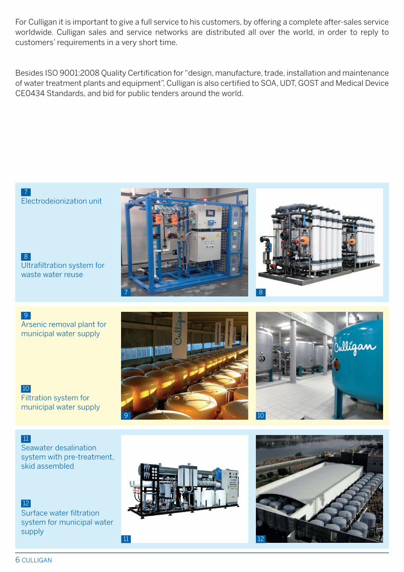
Seawater desalinationsystem with pre-treatment,skid assembled
Surface water filtrationsystem for municipal watersupply
Arsenic removal plant formunicipal water supply
Filtration system formunicipal water supply
Electrodeionization unit
Ultrafiltration system forwaste water reuse
7 8
9 10
11 12
7
8
9
10
11
12
For Culligan it is important to give a full service to his customers, by offering a complete after-sales serviceworldwide. Culligan sales and service networks are distributed all over the world, in order to reply tocustomers’ requirements in a very short time.
Besides ISO 9001:2008 Quality Certification for “design, manufacture, trade, installation and maintenanceof water treatment plants and equipment”, Culligan is also certified to SOA, UDT, GOST and Medical DeviceCE0434 Standards, and bid for public tenders around the world.
6 CULLIGAN

FILTRATION AND POTABILIZATION 7
Each model of Culligan filters can be selected witha choice of filtration media suitable for the specificapplication (see table on following page).
• FILTR-CLEER Multi-layer media typicallyemployed for the elimination of turbidity,suspended solids and low concentrations of heavymetals (e.g. Iron and Manganese).The main components are “Cullcite”, granular lowdensity anthracite in the upper layer of the filter,and “Cullsan”, long-lasting pure and chemicallyinert silica sand in the bottom layer.
• CULLAR Used for the removal of Chlorine,unpleasant tastes and odours. Cullar is a GranularActivated Carbon especially selected for itsextremely fine porosity and outstandingabsorption capacity.
• CULLNEU Used for neutralising acidic water,raising hardness level and reducing the corrosivecharacteristics of water. Cullneu is mostlycomposed by granular Calcium Carbonate, whichdissolves in water in direct proportion to theacidity removed; it therefore requires periodicrefilling.
• SUPER IRON Selective catalytic multi-layermedia for removing Iron, Manganese and Arsenic,which is activated using various oxidants.
• G.A.C. Granular Activated Carbon-based filter,designed specifically for adsorbing organics,pesticides, heavy metals and other hazardoussubstances.
• BIOFILTER Special filter designed for the removalof Ammonia through accelerated nitrification by abiomass of aerobic bacteria (Nitrosamonas andNitrobacter) supported by a layer of quartz-basedmedia. Biofilters can also oxidise and remove lowconcentrations of Iron and Manganese.
• UFX Specific media for the adsorption of Arsenicand Vanadium. The media cannot be regeneratedand must be replaced when exhausted. It is ideallyused for polishing water that has been pre-treatedwith less expensive processes.
• FHT Manual sand filters, suitable for heating andconditioning waters to eliminate Iron oxides,sludges and deposits that can cause a bad watercirculation in the entire circuit.
• OFSY® Double-stage filtration system, exclusiveto Culligan, ideally suited to remove elevated andvariable quantities of suspended solids. Theunique feature of this filter is its capacity todirectly treat water with elevated concentrationsof suspended solids, without any previousclarification.
FILTRATION ANDPOTABILIZATION
FILTRATION IS USED IN MANY APPLICATIONS.
REMOVE SUSPENDED SOLIDS FROM WATER, COARSE PARTICLES TO COLLOIDS•
ADSORBE AND REMOVE COLOURS, UNPLEASANT TASTES AND ODOURS, AS WELL AS•
ORGANIC AND INORGANIC CONTAMINANTS
REMOVE IRON, MANGANESE, ARSENIC AND OTHER HEAVY METALS •
NEUTRALISE WATER ACIDITY•
REMOVE AMMONIA THROUGH ACCELERATED NITRIFICATION IN BIOLOGICAL FILTERS•
THE APPROPRIATE MEDIA AND CHEMICAL CONDITIONING SHOULD BE SELECTED FOR THE
SPECIFIC APPLICATION.
MODELS

8 FILTRATION AND POTABILIZATION
Culligan’s pressure vessels are entirely fabricatedin our factories from high grade carbon steel withinternal linings of food-grade epoxy resins (250-300 µm), and external corrosion protection usingpolyurethane paint (80-100 µm).
HE Series automatic filters and FHT manual filtersare in reinforced fiberglass, corrosion proofmaterial. HE filter tanks only can be constructedaccording to Culligan Quadra-Hull™ system.
The automatic operation of filters is achieved viahydraulic diaphragm valves, driven by a pilot valveconnected to an electronic controller thatalternates service and wash cycles.Culligan HE automatic filters are controlled viahydraulic piston valve.Time, duration and frequency of wash cycles canbe programmed from the control panel.
An optional communication kit advises if the filterneeds service maintenance. The Culligan
controller (available for all Culligan MatrixSolutions™ filters) allows an easy checking andoperation of the unit.
Automatic flow regulators limit the water flow ratein the different phases, preventing any loss ofminerals during backwash and optimising filtrationefficiency during service.
MATERIALS
OPERATION
NOTE: details of each standard model are listed in the Technical Specifications tables.
HOW TO CHOOSE THE MOST APPROPRIATE FILTRATION MEDIA FOR YOUR NEEDS
NOTE: in addition to standard products, Culligan can design and supply customised units for larger applications and packagedcomplete systems either skid mounted or installed inside ISO containers. All systems are designed to the highest Standardsincluded DIN, ASME, RINA, etc.
Filtr-Cleer
UF
HE
HF6
Cullar
UR
Cullneu
UU
Super Iron
UFP
UFX FHT Bio-
filter
GAC OFSY
HF9 HE
HF6
HF9 HE
HF6
HF9 HE
HF6
HF9 HF9 BF
Turbidity uu uu uu uuu
Elevated and/or variable turbidity u uu uuu
Taste u uu
Odour u uu
uuu
uuu
Colour u uu
Atrazine and similar u
uuu
uuu
Tri-tetrachloroethylene and similar
Acidity uu
u uuu
uuu
Iron
Manganese
u uu uu uuu uu uu uuu
uu uu uuu uu uuu
Arsenic and Vanadium
Ammonia
u u uu u uu
u uuu u
uuu
u Acceptable uu Good uuu Excellent

HI-FLO 3e
HE
FHT
FILTRATION AND POTABILIZATION 9
MODEL FLOW RATE FITTINGS DIMENSIONS WEIGHTservice backwash in / out width depth height in operation shipping
max Ø
m3/h m3/h ” mm mm mm kg kg
FHT 500 0.5 1.5 ¾ 250 - 680 - 70
FHT 1000 1 3 ¾ 330 - 980 - 90
FHT 2500 2.5 4 1½ 700 850 1010 - -
NOTE Weights are approximate. • Dimensions may vary by ± 2%.
MODEL FLOW RATE FITTINGS DIMENSIONS WEIGHTservice backwash in / out width depth height in operation shipping
max Ø
m3/h m3/h ” mm mm mm kg kg
FILTR-CLEER (Turbidity)UF 12 2.6 2.3 1 ½ 356 610 1575 190 148
UF 14 3.6 3.4 1 ½ 356 610 1905 250 179
UF 16 4.7 4.5 1 ½ 406 610 1905 340 255
UF 21 8.1 6.8 1 ½ 533 610 1600 470 322
CULLAR (Taste - Odour - Colour)UR 12 1.8 1.8 1 ½ 356 610 1575 165 123
UR 14 2.5 2.3 1 ½ 356 610 1905 250 179
UR 16 3.2 3.4 1 ½ 406 610 1905 315 231
UR 21 5.4 5.7 1 ½ 533 610 1600 395 247
CULLNEU (Acidity)UU 12 1.8 1.8 1 ½ 356 610 1575 165 115
UU 14 2.5 2.3 1 ½ 356 610 1905 225 145
UU 16 3.2 3.4 1 ½ 406 610 1905 290 197
UU 21 5.4 6.8 1 ½ 533 610 1600 434 286
SSUPER IRON (Iron - Manganese)UFP 12 1.8 1.8 1 ½ 356 610 1575 190 140
UFP 14 2.1 3.4 1 ½ 356 610 1905 300 220
UFP 16 2.5 3.4 1 ½ 406 610 1905 365 272
UFP 21 3 6.8 1 ½ 533 610 1600 484 336
NOTE Weights are approximate. • Dimensions may vary by ± 2%.
MODEL FLOW RATE FITTINGS DIMENSIONS WEIGHTservice backwash in / out width depth height in operation shipping
max Ø
m3/h m3/h ” mm mm mm kg kg
FILTR-CLEER (Turbidity)UF 24 6.7 10 2 610 - 2179 650 505
CULLAR (Taste - Odour - Colour)UR 24 6.7 4.5 2 610 - 2179 560 411
UR 30 11 6.8 2 762 - 2179 955 655
SUPER IRON (Iron - Manganese)UFP 24 4.5 7 2 610 - 2179 710 561
UFP 30 7 10 2 762 - 2179 1130 880
CULLAX (Arsenic - Vanadium)UFX 21 3 3 2 533 - 1925 450 376
UFX 24 4.5 4.5 2 610 - 2179 720 561
UFX 30 6.8 6.8 2 762 - 2179 1160 905
NOTE Weights are approximate. • Dimensions may vary by ± 2%.

HI-FLO 9
10 FILTRATION AND POTABILIZATION
MODEL FLOW RATE FITTINGS DIMENSIONS WEIGHTservice backwash in / out width depth hight in operation shipping
max Ø
m3/h m3/h mm mm mm kg kg
FILTR-CLEER (Turbidity)UF 20 4.7 7.9 1 ½” 710 735 1950 770 470
UF 24 6.7 10.9 1 ½” 710 835 1985 1100 680
UF 30 11 15.9 1 ½” 765 985 2050 1700 1030
UF 36 17 27.3 2 ” 975 1215 2131 2980 1910
UF 48 27 40.9 2 ½” 1258 1436 2235 4490 2790
UF 54 37 56 2 ½” 1432 1632 2367 4800 3100
UF 60 42 61.3 DN 80 1500 1760 2700 5500 4050
UF 72 60 90.8 DN 100 1800 2150 2782 6400 5450
UF 84 80 129.4 DN 100 2100 2450 3090 10650 7700
UF 90 86 147.7 DN 100 2300 2630 3100 12450 9010
UF 100 117 174.9 DN 150 2500 2950 3364 16100 11700
UFe 100 117 174.9 DN 100 2500 2850 3314 16100 11700
UF 120 170 250 DN 150 3000 3490 3600 32000 18800
CULLAR (Taste - Odour - Colour)UR 20 4.7 3.4 1 ½” 710 735 1950 760 460
UR 24 6.7 4.5 1 ½” 710 835 1985 1030 600
UR 30 11 6.8 1 ½” 765 985 2050 1600 930
UR 36 17 10.9 2” 975 1215 2131 2720 1650
UR 48 27 18.2 2” 1258 1465 2235 3500 2410
UR 54 37 25 2 ½” 1432 1626 2367 4250 2950
UR 60 42 27.3 DN 80 1500 1760 2700 4500 3350
UR 72 60 40.9 DN 80 1800 2100 2782 5550 4600
UR 84 80 52.2 DN 100 2100 2450 3090 8100 5900
UR 90 86 61.8 DN 100 2300 2630 3100 9806 7600
UR 100 117 79.5 DN 100 2500 2850 3314 11100 9400
UR 120 170 114 DN 150 3000 3490 3600 29000 15250
SUPER IRON (Iron - Manganese)UFP 20 3 5.7 1 ½” 710 735 1950 770 470
UFP 24 4.5 7.9 1 ½” 710 835 1985 1100 680
UFP 30 7 13.6 1 ½” 765 985 2050 1700 1030
UFP 36 11 20.5 2” 975 1215 2131 2980 1910
UFP 48 18 31.9 2 ½” 1258 1436 2235 4490 2790
UFP 54 25 45.8 2 ½” 1432 1632 2367 4800 3100
UFP 60 28 52.2 DN 80 1500 1760 2700 5700 4300
UFP 72 40 68 DN 100 1800 2150 2782 7000 5900
UFP 84 52 95.5 DN 100 2100 2450 3090 11700 8700
UFP 90 58 114 DN 100 2300 2630 3100 14000 10560
UFP 100 79 143 DN 150 2500 2950 3364 17900 13200
UFPe 100 79 143 DN 100 2500 2850 3314 17900 13200
UFP 120 112 200 DN 150 3000 3490 3600 34600 20500
NOTE Weights are approximate. • Dimensions may vary by ± 2%.

HI-FLO 9
FILTRATION AND POTABILIZATION 11
MODEL FLOW RATE FITTINGS DIMENSIONS WEIGHTservice backwash in / out width depth height in operation shipping
max Ø
m3/h m3/h mm mm mm kg kg
CULLAX (Arsenic - Vanadium) UFX 20 3 3 1 ½” 710 735 1950 760 460
UFX 24 4.5 4.5 1 ½” 710 835 1985 1020 600
UFX 30 6.8 6.8 1 ½” 765 985 2050 1590 930
UFX 36 10.9 10.9 2” 975 1215 2131 2550 1650
UFX 48 17 17 2” 1258 1465 2235 4060 2410
UFX 54 25 25 2 ½” 1432 1626 2367 5050 2950
UFX 60 27.3 27.3 DN 80 1500 1760 2700 5975 3350
UFX 72 40 40 DN 80 1800 2100 2782 8350 4600
UFX 84 52.2 52.2 DN 100 2100 2450 3090 11150 5900
UFX 90 61.8 61.8 DN 100 2300 2630 3100 13900 7600
UFX 100 75 75 DN 100 2500 2850 3364 16900 9400
UFX 120 105 105 DN 100 3000 3490 3600 24750 13250
BIOLOGICAL FILTERS (Ammonia - Iron - Manganese)BF 48 17 36 2” 1258 1465 2235 4150 2500
BF 54 22.5 47 2 ½” 1432 1626 2367 5150 3050
BF 60 26 54 DN 80 1500 1760 3200 6325 3700
BF 72 38 80 DN 80 1800 2100 3282 8650 4900
BF 84 52 108 DN 100 2100 2450 3590 11350 6100
BF 90 62 126 DN 100 2300 2630 3660 14200 7900
BF 100 72 144 DN 100 2500 2850 3814 17300 9800
BF 120 106 216 DN 100 3000 3490 4100 25200 13700
CULLNEU (Acidity)UU 20 3 7.9 1 ½” 710 735 1950 830 530
UU 24 4.5 10.9 1 ½” 710 835 1985 1150 725
UU 30 7 15.9 1 ½” 765 985 2050 1780 1110
UU 36 11 27.3 2” 975 1215 2131 3030 1955
UU 48 18 40.9 2 ½” 1258 1436 2235 4785 3085
UU 54 25 56 2 ½” 1432 1632 2367 5100 3250
NOTE Weights are approximate. • Dimensions may vary by ± 2%.

12 FILTRATION AND POTABILIZATION
MODEL FLOW RATE FITTINGS DIMENSIONS WEIGHTservice backwash in / out width depth height in operation shipping
max Ø
m3/h m3/h DN mm mm mm kg kg
FILTR-CLEER (Turbidity)UF 60 36,2 61.3 80 1500 1760 2200 4640 3290
UF 72 52 90.8 100 1800 2150 2282 6455 4655
UF 84 70.4 129.4 100 2100 2450 2340 8325 5825
UF 90 81.6 147.7 100 2300 2630 2350 12250 7250
UF 100 101.2 174.9 150 2500 2950 2614 13445 9145
UFe 100 101.2 174.9 100 2500 2850 2564 13445 9145
UF 120 145 250 150 3000 3490 2890 27000 15500
CULLAR (Taste - Odour - Colour)UR 60 36.2 27.3 80 1500 1760 2200 4395 2795
UR 72 52 40.9 80 1800 2100 2282 6025 3875
UR 84 70.4 52.2 100 2100 2450 2340 8190 5190
UR 90 81.6 65 100 2300 2630 2350 11200 6080
UR 100 101.2 79.5 100 2500 2850 2564 12250 7750
UR 120 145 114 150 3000 3490 2890 25000 13400
CULLNEU (Acidity)UU 60 22.7 61.3 80 1500 1760 2200 4640 3290
UU 72 32.7 90.8 80 1800 2150 2282 6455 4655
UU 84 40.9 129.4 100 2100 2450 2340 8325 5825
UU 90 47 147.7 100 2300 2630 2350 12290 7250
UU 100 59 174.9 150 2500 2950 2614 13445 9145
UUe 100 59 174.9 100 2500 2850 2564 13445 9145
UU 120 80 250 150 3000 3490 2890 27000 15500
SUPER IRON (Iron - Manganese)UFP 60 28 52.2 80 1500 1760 2200 4800 3310
UFP 72 40 68 100 1800 2150 2282 6750 4750
UFP 84 52 95.5 100 2100 2450 2340 8600 6100
UFP 90 58 114 100 2300 2630 2350 12500 7500
UFP 100 79 143 150 2500 2950 2614 12900 9500
UFPe 100 79 143 100 2500 2850 2564 12900 9500
UFP 120 112 200 150 3000 3490 2890 27250 15750
HI-FLO 6
NOTE Weights are approximate. • Dimensions may vary by ± 2%.
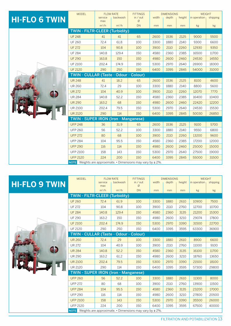
FILTRATION AND POTABILIZATION 13
MODEL FLOW RATE FITTINGS DIMENSIONS WEIGHTservice backwash in / out width depth height in operation shipping
max Ø
m3/h m3/h DN mm mm mm kg kg
HI-FLO 6 TWINTWIN - FILTR-CLEER (Turbidity)UF 248 41 41 65 2600 1536 2125 9000 5500
UF 260 72.4 61.8 100 3300 1880 2140 9300 6600
UF 272 104 90.8 100 3900 2110 2260 12930 9350
UF 284 140.8 129.4 150 4580 2360 2385 16500 11700
UF 290 163.8 150 150 4980 2600 2460 24530 14550
UF 2100 202.4 174.9 150 5300 2970 2640 26900 18300
UF 2120 290 250 150 6400 3395 2845 54000 31000
TWIN - CULLAR (Taste - Odour - Colour)UR 248 41 18.2 65 2600 1536 2125 8100 4600
UR 260 72.4 29 100 3300 1880 2140 8800 5600
UR 272 104 40.9 100 3900 2110 2260 12070 7770
UR 284 140.8 52.2 150 4580 2360 2385 16400 10400
UR 290 163.2 68 150 4980 2600 2460 22420 12200
UR 2100 202.4 79.5 150 5300 2970 2640 24530 15530
UR 2120 290 114 150 6400 3395 2845 50030 26850
TWIN - SUPER IRON (Iron - Manganese)UFP 248 36 31.9 65 2600 1536 2125 9100 5700
UFP 260 56 52.2 100 3300 1880 2140 9550 6800
UFP 272 80 68 100 3900 2110 2260 13200 9600
UFP 284 104 95.5 150 4580 2360 2385 17200 12000
UFP 290 116 114 150 4980 2600 2460 25000 15000
UFP 2100 158 143 150 5300 2970 2640 27500 19000
UFP 2120 224 200 150 6400 3395 2845 55000 31500
NOTE Weights are approximate. • Dimensions may vary by ± 2%.
MODEL FLOW RATE FITTINGS DIMENSIONS WEIGHTservice backwash in / out width depth height in operation shipping
max Ø
m3/h m3/h DN mm mm mm kg kg
HI-FLO 9 TWINTWIN - FILTR-CLEER (Turbidity)UF 260 72.4 61.9 100 3300 1880 2610 10900 7500
UF 272 104 90.8 100 3900 2110 2760 12700 10700
UF 284 140.8 129.4 150 4580 2360 3135 21200 15300
UF 290 163.2 150 150 4980 2600 3210 29074 17800
UF 2100 202.4 174.9 150 5300 2970 3390 31500 22700
UF 2120 290 250 150 6400 3395 3595 63300 36900
TWIN - CULLAR (Taste - Odour - Colour)UR 260 72.4 29 100 3300 1880 2610 8900 6600
UR 272 104 40.9 100 3900 2110 2760 11000 9100
UR 284 140.8 52.2 150 4580 2360 3135 16100 11700
UR 290 163.2 61.2 150 4980 2600 3210 18760 13650
UR 2100 202.4 79.5 150 5300 2970 3390 21500 18100
UR 2120 290 114 150 6400 3395 3595 57300 29800
TWIN - SUPER IRON (Iron - Manganese)UFP 260 56 52.2 100 3300 1880 2610 11300 8000
UFP 272 80 68 100 3900 2110 2760 13900 11500
UFP 284 104 95.5 150 4580 2360 3135 23200 17000
UFP 290 116 114 150 4980 2600 3210 27800 20500
UFP 2100 158 143 150 5300 2970 3390 35500 26000
UFP 2120 224 200 150 6400 3395 3595 67500 40000
NOTE Weights are approximate. • Dimensions may vary by ± 2%.

14 FILTRATION AND POTABILIZATION
OFSYMODEL FLOW RATE FITTINGS DIMENSIONS WEIGHT
service backwash in / out width depth height in operation shippingmax Ø
m3/h m3/h DN mm mm mm kg kg
OFSY 20 4.5 7.9 1 ½” 1100 880 1960 1320 1050
OFSY 24 5.7 10.9 1 ½” 1200 980 2000 1820 1400
OFSY 30 9.1 15.9 1 ½” 1600 1130 2050 2820 2110
OFSY 36 13.6 27.3 2 ½” 2010 1480 2130 4350 3400
OFSY 48 21.8 40.9 2 ½” 2500 1730 2235 7800 5600
OFSY 54 29.6 56.8 2 ½” 2920 1930 2367 8800 6000
OFSY 60 36.3 61.3 DN 80 3200 1760 2150 10500 7200
OFSY 72 50 90.8 DN 100 3750 2150 2150 15000 10500
OFSY 84 68.1 129.4 DN 100 4350 2450 2160 20000 14000
OFSY 90 82 159 DN 100 4750 2600 2250 25000 17000
OFSY 100 100 174.9 DN 150 5200 2950 2370 29500 21000
OFSY 120 139 250 DN 150 6300 3430 2890 54000 31000
NOTE Weights are approximate. • Dimensions may vary by ± 2%.
NOTE Weights are approximate. • Dimensions may vary by ± 2%.
G.A.C.MODEL FLOW RATE FITTINGS DIMENSIONS WEIGHT
service backwash in / out width depth height in operation shippingmax Ø
m3/h m3/h DN mm mm mm kg kg
G.A.C. 20 3 3.4 1” 500 660 2480 800 500
G.A.C. 24 4.5 4.5 1” 600 760 2515 1100 700
G.A.C. 30 7 7 1 ½” 750 1020 2585 1700 1000
G.A.C. 36 10.8 11 1 ½” 950 1217 2650 2900 1850
G.A.C. 48 18 18 2 ½” 1200 1470 2770 4500 2700
G.A.C. 60 27 28 2 ½” 1500 1770 3000 5600 4000
G.A.C. 72 40 41 DN 80 1800 2100 3110 7500 5500
G.A.C. 84 54 55 DN 80 2100 2400 3160 9800 7000
G.A.C. 90 60 60 DN 100 2300 2705 3370 11200 8500
G.A.C. 100 80 80 DN 100 2500 2850 3420 12500 10000
G.A.C. 120 108 113 DN 100 3000 3430 3890 30000 18000
OPERATING DATAHE HI-FLO 3e FHT HI-FLO 6 / HI-FLO 9 / TWIN / OFSY / G.A.C.
2 barMinimum operating pressure 2 bar 4 bar 1.5 bar
8.3 barMaximum operating pressure 7 bar 4 bar 7 bar up to model 60”
5 bar for the larger models
0.5-49 °COperating temperature 4-50 °C 5-50 °C 5-40 °C
Power supply 110/230/24 V
50/60 Hz
110/230/24 V
50/60 Hz
230/24 V
50/60 Hz
only mod. 2500
230 V 50/60 Hz
22 WPower consumption 10 W only mod. 2500
10 W
10 W
Pressure loss Hi-Flo 6, Hi-Flo 9, TWIN: UF 1 bar; UR 0.3 bar; UU and UFP: 0.5 bar
OFSY and G.A.C. 0.5 bar
UF 1 bar; UR 0.3 bar
UFP and UFX 0.5 bar
0.1-0.9 bar --

Self-cleaning filters remove suspended solids fromwater without replacing filter cartridges. Available infully automatic or semi-automatic versions withdifferent capacities and filtration levels.From 1” to 2½” models, filtering elements aremanufactured in AISI 316 stainless steel woven wiremesh, and cleansing from retained impurities is madeby reverse water jet flow.The cartridges are available in a range from 50 to500 µ.
For high capacity applications EASY MAX self-cleaningfilters with 2” fittings (threaded) and ND 65-80-100(flanged) are available.In semi-automatic models the action of the jet isinitiated by manual adjustment. In fully automaticmodels, a timer-programmer controls the washingintervals, between 1 and 999 hours.EASY-MAX filters, in accordance to CE Standards, aresuitable for civil applications, with electromagneticappliance.
SELF-CLEANING FILTERS ARE A HIGHLY FLEXIBLE, VERSATILE AND ECONOMICAL SOLUTION FOR
ADDRESSING SMALL SCALE WATER FILTRATION PROBLEMS. THEY ARE COMMONLY USED AS
BARRIER AGAINST SUSPENDED SOLIDS FOR PROTECTING SENSITIVE EQUIPMENT.
MODELS
SELF-CLEANINGFILTERS
SELF-CLEANING FILTERS 15
MODEL FLOW RATE FITTINGS DIMENSIONS WEIGHTmax Ø Ø x height shipping
m3/h mm kg
EASY MAXEASY MAX semi-automatic 30 2” 317 x 332 10.5
EASY MAX semi-automatic 38 DN 65 252 x 332 13.5
EASY MAX semi-automatic 50 DN 80 252 x 344 13.5
EASY MAX semi-automatic 52 DN 100 252 x 344 14.5
EASY MAX/A automatic 30 2” 317 x 346 11
EASY MAX/A automatic 38 DN 65 252 x 346 13
EASY MAX/A automatic 50 DN 80 252 x 358 14
EASY MAX/A automatic 52 DN 100 252 x 358 15
NOTE Maximum operating pressure: 16 bar • Maximum temperature water/room: 80 / 40 °CPower supply: 220/24 V - 50 Hz
SELF-CLEANINGFILTER
FAS
MODEL FLOW RATE FITTINGS DIMENSIONS WEIGHTat 0,2 bar Ø Ø x height shipping
m3/h ” mm kg
FAS semi-automatic 6 1 150 x 345 2.7
FAS semi-automatic 8 1 ½ 150 x 345 3.2
EASY semi-automatic 6 1 110 x 300 2.8
EASY semi-automatic 8 1 ½ 110 x 300 3.4
EASY semi-automatic 9.5 2 110 x 300 3.7
EASY A automatic 6 1 110 x 380 4.3
EASY A automatic 8 1 ½ 110 x 380 4.9
EASY A automatic 9.5 2 110 x 380 5.2
NOTE Maximum operating pressure: 16 bar • Maximum temperature water/room: 80 / 40 °CPower supply: 220/24 V - 50 Hz
EASY EASY A

CULLIGAN DYNAMIC SEPARATORS ARE DESIGNED TO REDUCE HIGH TURBIDITY SUSPENDED
SOLIDS FROM WATER, SUCH AS SAND AND GENERAL ORGANIC SUBSTANCES.
IF USED AS PRE-TREATMENT OF THE TRADITIONAL FILTERS, THEY PROLONG FILTRATION CYCLES
AND FILTERING MINERALS USE, AND REDUCE WASH FREQUENCY.
The 5 models with fittings from 1” to 3” areexternally painted carbon steel constructed,suitable for not corrosive water.
Culligan Dynamic Separators are designed toseparate solids from water by means of centrifugalforce. Water enters the top of the unit tangentially and(through internal slots) is drawn into the chamberwhere the separation of solids from water occurs.Water flows down this chamber where thecentrifugal force gives rise to the separation of
those solids having the higher specific weight.These solids fall by gravity and accumulates in thecollection chamber of the unit. Water freed fromsuspended solids is then drawn into the vortex andup to the separator outlet.
MATERIALS
OPERATION
16 DYNAMIC SEPARATORS
DYNAMICSEPARATORS
Maximum operating temperature: 70 °C • Minimum operating pressure: 1 bar • Maximum pressure: 8 bar.
NOTE Weights are approximate. • Dimensions may vary by ± 2%.
MODEL FLOW RATE FITTINGS COLLECTIONCHAMBERCAPACITY
DIMENSIONS WEIGHT
in operation shippingdiameter x heightDrainin / outmaxmin.
m3/h m3/h “ “ litres mm kg kg
DSA 1
DSA 1.5
DSA 1.25
DSA 2
DSA 2.5
DSA 3
4.5 7.5 1 ¾ 1.2 152 x 762 17 11
6.5 11 1¼ ¾ 1.2 152 x 762 17 11
10.5 16 1½ ¾ 1.2 152 x 762 18 11
14.5 24 2 ¾ 3 219 x 854 45 22
21.5 35 2½ ¾ 4.7 219 x 940 50 25
33.5 66 3 ¾ 8.3 273 x 1067 80 46

WATER SOFTENING 17
• HE & HE TWIN, for use in apartment blocks,commercial or light industrial settings, maximumflow rate 8.4 m3/h, with pressure loss 1.7 bar
• HI-FLO 3e, for large commercial and industrialapplications, maximum flow rate 22.7 m3/h
• ULTRA LINE, HA and HB ranges, for industrialapplications, maximum flow rate 227 m3/h
NOTE: details of each standard models are listed in the technicalspecifications tables.
SOFTENING IS THE REMOVAL OF HARDNESS FROM WATER. REMOVAL IS OBTAINED THROUGH
THE EXCHANGE OF CALCIUM AND MAGNESIUM IONS WITH SODIUM, WHICH DO NOT FORM
DEPOSITS OR SCALE. RAW WATER IS PASSED THROUGH A LAYER OF RESIN PREVIOUSLY LOADED
WITH SODIUM, USING SODIUM CHLORIDE. CULLIGAN’S CULLEX FOOD-GRADE EXCHANGE RESIN
IS HIGHLY RESISTANT TO MECHANICAL WEAR, LONG-LASTING, AND SALT-EFFICIENT.
POTASSIUM CHLORIDE CAN ALSO BE USED FOR RESIN REGENERATION, FOR SUITABLE
APPLICATIONS.
MODELS
Exchange resins tanks in the HE & HE Twin rangesare “Quadra-Hull” or PE liner reinforced withfiberglass or epoxy resin.Culligan Quadra-Hull™ tanks are in reinforcedfiberglass, with internal food-grade lining andexternal ABS jacket, against wet and UV rays.Tanks used in Hi-Flo 3e range are in PE linerreinforced with fiberglass or epoxy resin, while theones in the Ultra Line HA and HB range are madefrom high grade carbon steel, internal lining isfood-grade epoxy resins, and external protection ispolyurethane paint.
MATERIALS
Valves are in plastic material for all models of HE,HE Twin and Ultra Line (up to 1550 model) range,while in the Hi-Flo 3e range are in Bronze.For Ultra Line models from 1700, valves are in castiron and flanged piping in stainless steel, internallyand externally protected with epoxy paint.
NOTE Specific resin can be used for Nitrate removal. Our specialist application engineers department willprovide you with appropriate specifications for converting water softeners into Nitrate removal units.
WATER SOFTENING

18 WATER SOFTENING
All Culligan water softeners are fully automatic.HE, HE Twin and Hi-Flo 3e models are suppliedwith a distribution motorized piston valve and witha multi-function programmer for operation phasesmanaging (service, wash, regeneration).All Ultra Line models are supplied with a completebutterfly valve distribution group, and operatingphases (service, wash, regeneration) arecontrolled by an electronic control board whichstarts valves by means of a distribution pilot.Volumetric operation is available, to startregeneration phase in accordance with suppliedwater quantity.A pulse-emitter turbine (or a water meter)controls the water volume, and the electroniccontrol panel starts the regeneration phase whenpreset water volume is reached.Regeneration can also be started manually,without modifying the preset automatic phase.
Duplex and/or Triplex softeners are also available,allowing (once resins are exhausted) to activate asecond unit while the other starts regenerationphase.In addition, for HE range the Progressive Flowmodels are available, which allow to managemultiple softening columns in parallel, to satisfypeak demand for treated water softener withouthaving to oversize the softener itself.With these features it is possible to ensurecontinuous flow of softened water.
Disinfecting systems for water softeners areavailable as an option.
All water softeners can be equipped with BrineSystem (salt container) of different size accordingto available space and operational requirements.
OPERATION
• cooling systems• hot water producers• low pressure boilers• textile industry• food industry• ceramic industry• pharmaceutical industry
PRINCIPAL APPLICATIONS
• professional kitchens• hotels• restaurants• bakeries• professional laundries and cleaners• car wash• animal farms
MODEL FITTINGS EXCHANGE CULLEX DIMENSIONS WEIGHTin / out CAPACITY resin tank salt tank
Ø max H Ø height Ø in operation shipping
” m3 •°f litres m3/h @ bar mm mm mm kg kg
NOTE Weights are approximate. • Dimensions may vary by ± 2%. • Available for Duplex installations.
HEHE 20 1 150 20 2.8 @ 1 229 1067 457 260 55
HE 40 1 356 40 2.8 @ 1 254 1372 457 290 77
HE 60 1 401 56 2.8 @ 1 305 1321 610 490 115
HE 90 1 589 85 2.8 @ 1 356 1651 610 560 152
HE 60 1 ½ 395 56 8.4 @ 1.7 356 1321 610 525 112
HE 90 1 ½ 621 85 8.4 @ 1.7 406 1321 610 550 135
HE 120 1 ½ 887 113 8.4 @ 1.7 406 1651 610 735 170
HE 150 1 ½ 977 142 8.4 @ 1.7 533 1346 762 1030 240
HE 210 1 ½ 1521 198 8.4 @ 1.7 533 1575 762 1180 295
SERVICEFLOW RATE
@PRESSURE LOSS
H The exchange capacity is calculated assuming water hardness equal to 40 °f (400 ppm CaCO3) andsalinity equal to 500 ppm, free from colour, oil, and turbidity, at continuous operation flow rate. Capacitymay vary in accordance to other parameters, such as the percentage of Chlorides, water pressure, andthe purity and type of regenerant.
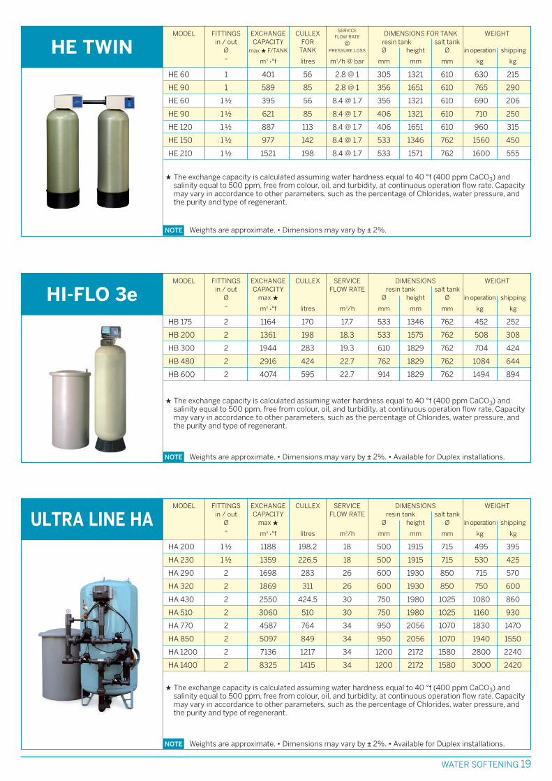
NOTE Weights are approximate. • Dimensions may vary by ± 2%. • Available for Duplex installations.
MODEL FITTINGS EXCHANGE CULLEX SERVICE DIMENSIONS WEIGHTin / out CAPACITY FLOW RATE resin tank salt tank
Ø max H Ø height Ø in operation shipping
” m3 •°f litres m3/h mm mm mm kg kg
HI-FLO 3eHB 175 2 1164 170 17.7 533 1346 762 452 252
HB 200 2 1361 198 18.3 533 1575 762 508 308
HB 300 2 1944 283 19.3 610 1829 762 704 424
HB 480 2 2916 424 22.7 762 1829 762 1084 644
HB 600 2 4074 595 22.7 914 1829 762 1494 894
H The exchange capacity is calculated assuming water hardness equal to 40 °f (400 ppm CaCO3) andsalinity equal to 500 ppm, free from colour, oil, and turbidity, at continuous operation flow rate. Capacitymay vary in accordance to other parameters, such as the percentage of Chlorides, water pressure, andthe purity and type of regenerant.
WATER SOFTENING 19
MODEL FITTINGS EXCHANGE CULLEX DIMENSIONS FOR TANK WEIGHTin / out CAPACITY FOR resin tank salt tank
Ø max H F/TANK TANK Ø height Ø in operation shipping
” m3 •°f litres m3/h @ bar mm mm mm kg kg
NOTE Weights are approximate. • Dimensions may vary by ± 2%.
HE TWINHE 60 1 401 56 2.8 @ 1 305 1321 610 630 215
HE 90 1 589 85 2.8 @ 1 356 1651 610 765 290
HE 60 1 ½ 395 56 8.4 @ 1.7 356 1321 610 690 206
HE 90 1 ½ 621 85 8.4 @ 1.7 406 1321 610 710 250
HE 120 1 ½ 887 113 8.4 @ 1.7 406 1651 610 960 315
HE 150 1 ½ 977 142 8.4 @ 1.7 533 1346 762 1560 450
HE 210 1 ½ 1521 198 8.4 @ 1.7 533 1571 762 1600 555
H The exchange capacity is calculated assuming water hardness equal to 40 °f (400 ppm CaCO3) andsalinity equal to 500 ppm, free from colour, oil, and turbidity, at continuous operation flow rate. Capacitymay vary in accordance to other parameters, such as the percentage of Chlorides, water pressure, andthe purity and type of regenerant.
SERVICEFLOW RATE
@PRESSURE LOSS
NOTE Weights are approximate. • Dimensions may vary by ± 2%. • Available for Duplex installations.
MODEL FITTINGS EXCHANGE CULLEX SERVICE DIMENSIONS WEIGHTin / out CAPACITY FLOW RATE resin tank salt tank
Ø max H Ø height Ø in operation shipping
” m3 •°f litres m3/h mm mm mm kg kg
ULTRA LINE HAHA 200 1 ½ 1188 198.2 18 500 1915 715 495 395
HA 230 1 ½ 1359 226.5 18 500 1915 715 530 425
HA 290 2 1698 283 26 600 1930 850 715 570
HA 320 2 1869 311 26 600 1930 850 750 600
HA 430 2 2550 424.5 30 750 1980 1025 1080 860
HA 510 2 3060 510 30 750 1980 1025 1160 930
HA 770 2 4587 764 34 950 2056 1070 1830 1470
HA 850 2 5097 849 34 950 2056 1070 1940 1550
HA 1200 2 7136 1217 34 1200 2172 1580 2800 2240
HA 1400 2 8325 1415 34 1200 2172 1580 3000 2420
H The exchange capacity is calculated assuming water hardness equal to 40 °f (400 ppm CaCO3) andsalinity equal to 500 ppm, free from colour, oil, and turbidity, at continuous operation flow rate. Capacitymay vary in accordance to other parameters, such as the percentage of Chlorides, water pressure, andthe purity and type of regenerant.

OPERATING DATAHE / HE TWIN HI-FLO 3e ULTRA LINE HA e HB
Minimum operating pressure
Maximum operating pressure
Operating temperature
Pressure loss
Power supply
Power consumption
1.4 bar for models 1”
1.7 bar for models 1.5”2 bar 2 bar
8.6 bar for models 1”
8.3 bar for models 1.5”8.5 bar 7 bar from mod. 200 to mod. 2100
5 bar for other models
0-49 °C for models 1”
4.4-38 °C for models 1.5”1-40 °C 1-40 °C
from 0.8 to 1 bar for models 1”
from 1 to 1.7 bar for models 1.5”
~0.5 bar at medium flow rate
~1.5 bar at maximum flow rate
~0.5 bar at medium flow rate
~1.5 bar at maximum flow rate
230/24 V - 50/60 Hz 230/24 V - 50/60 Hz 110/230/24 V - 50/60 Hz
8.4-21.61 W 20 W 20 W
NITRATE REMOVAL
2 bar
7 bar for models up to 1700
5 bar for model 2500
2-40 °C
0.3 - 0.6 bar
110/230/24 V - 50/60 Hz
10 W
20 WATER SOFTENING
MODEL FITTINGS EXCHANGE CULLEX SERVICE DIMENSIONS WEIGHTin / out CAPACITY FLOW RATE resin tank salt tank
Ø max H Ø height Ø in operation shipping
” m3 •°f litres m3/h mm mm mm kg kg
ULTRA LINE HBHB 770 2 ½ 4587 764 50 950 2056 1070 1840 1480
HB 850 2 ½ 5097 849 50 950 2056 1070 1950 1550
HB 1200 2 ½ 7136 1217 50 1200 2172 1580 2810 2250
HB 1400 2 ½ 8325 1415 50 1200 2172 1580 3010 2430
HB 1550 2 ½ 8825 1500 60 1400 2392 1580 4200 2580
HB 1700 4 10430 1568 114 1500 2620 1580 6105 3355
HB 2100 4 11390 1904 114 1500 2620 1580 6354 3644
HB 2500 4 16050 2296 114 1800 2660 BRINE MAKERu 8480 4500
HB 3000 4 18480 2632 114 1800 2660 BRINE MAKERu 8760 4790
HB 4500 6 28500 4032 227 2100 3030 BRINE MAKERu 13080 7300
HB 6600 6 42900 6020 227 2500 3100 BRINE MAKERu 19585 10485
NOTE Weights are approximate. • Dimensions may vary by ± 2%. • Available for Duplex installations.
u See separate Data Sheet for concrete Brine Maker dimensions.
H The exchange capacity is calculated assuming water hardness equal to 40 °f (400 ppm CaCO3) andsalinity equal to 500 ppm, free from colour, oil, and turbidity, at continuous operation flow rate. Capacitymay vary in accordance to other parameters, such as the percentage of Chlorides, water pressure, andthe purity and type of regenerant.
MODEL FITTINGS EXCHANGE CULLEX SERVICE DIMENSIONS WEIGHTin / out CAPACITY FLOW RATE resin tank salt tank
Ø max H Ø height Ø in operation shipping
l g NO3/kg salt litres m3/h mm mm mm kg kg
NITRATE REMOVALHB 200 2 ” 3000/40 200 4 600 2000 850 885 460
HB 300 2 ½ ” 5200/70 350 7 750 2050 850 1330 665
HB 600 3 ” 9000/120 600 12 950 2130 1070 2375 1305
HB 1000 3 ” 15000/200 1000 20 1200 2400 1580 3660 1780
HB 1700 DN 100 25500/340 1700 34 1500 2620 1580 6105 3355
HB 2500 DN 100 37500/500 2500 50 1800 2660 BRINE MAKERu 8480 4500
NOTE Weights are approximate. • Dimensions may vary by ± 2%.
u See separate Data Sheet for concrete Brine Maker dimensions.
l Fittings: threaded 2” and 3”; flanged DN 100 and 150. The diameters indicated refer only to Nitrateremoval unit pipework and not to connections to piping systems
H The exchange capacity is calculated assuming water hardness of 100 ppm max as NO3, salinity equal to500 ppm, free from color, oil, and turbidity, at continuous operation flow rate. Capacity may vary inaccordance to other parameters, such as the percentage of sulphates, alkalinity, Nitrates, water pressure,treated water drawing, purity and type of regenerant.

TO COMPLETE WATER TREATMENT SYSTEMS, CULLIGAN HAS DEVELOPED AND CUSTOMIZED A
RANGE OF DOSING SYSTEMS, WHICH INCLUDE SPECIFIC ELECTROMAGNETIC PUMPS
(ANALOGUE INTERFACE), STORAGE TANKS, CHEMICALS AND DOSING ANALYSIS CONTROL
BOARDS.
DOSING SYSTEMS
For each model the following accessories areavailable:
• chemical tanks, of various sizes, depending onapplication
• minimum level switch for Chemicals tank
Accessories• wall-mounting brackets
• water meter with pulse emitter
• anti-syphon kit
Dosing pumps are widely used in water treatment.Correct dosing of chemical products is the basefor good operation of any water treatment wherewater quality is critical, for potabilization, boilers,pool conditioning, and any other industrial orprivate systems.Culligan produces solenoid driven meteringpumps with analogue or digital interface.All parts in contact with water are made incorrosion resistant material, like PVDF, Viton, PTFEand ceramics.
The following models are available:
• BASIC2 Continuous operation or controlled viaON-OFF switch.
• PROP2 Continuous operation, controlled via ON-OFF switch or pulse emitter.
• LOGIC2 Continuous operation, controlled viapulse emitter, or proportional to regulating4-20 mA signal.
DOSING PUMPS
DOSING SYSTEMS 21
NOTE Power supply 110/240 V - 50/60 Hz - single phase • Protection degree IP 65
MODELS NOMINALCAPACITY
l/h
BASIC2 40 • PROP2 40 • LOGIC2 40
BASIC2 130 • PROP2 130 • LOGIC2 130
BASIC2 80 • PROP2 80 • LOGIC2 80
BASIC2 400 • PROP2 400 • LOGIC2 400
4
6
13
40
PRESSUREmax
bar
10
8
8
2
VOLUME/STROKE
cm3
0.55
0.83
0.72
2.22
STROKESPER MINUTE
max
120
160
300
300
POWERCONSUMPTION
W
17
18
32
30
WEIGHT
kg
3.6
4.1
4.1
4.1
OPERATION: BASIC2 continuous or ON/OFF switchPROP2 continuous or pulse emitterLOGIC2 continuous or 4-20 mA signal

22 INSTRUMENTATION AND CONTROLS
INDUSTRIAL WATER TREATMENT PROCESSES REQUIRE CLOSE CONTROL AND MONITORING OF
SEVERAL CRITICAL PARAMETERS TO ENSURE WATER QUALITY. THE MOST IMPORTANT BEING
TEMPERATURE, pH, CONDUCTIVITY, REDOX, RESIDUAL CHLORINE.
CULLIGAN OFFERS A COMPLETE RANGE OF MONITORING INSTRUMENTS FOR USE IN WATER
TREATMENT SYSTEMS.
pH-METER Mod. S508-pH (CONTROL PANEL)
Technical data• Standard range: 0-14 pH• Display: LCD• Power output: 2 off 0-20/4-20 mA dc. load ≤ 600 Ohm• Protection degree: IP 54
Mod. S507-pH (WALL) - S507-pH (PANEL)
Technical data• Standard range: 0-14 pH• Display: LCD• Power output: 2 off 0-20/4-20 mA dc. Maximum load 600 Ohm• Protection degree: IP 66
The Automatic Blow Down for Cooling Towers includes a programmingcontrol board, a conductivity meter, a conductivity cell for a constantconductivity projection, a motorized valve, a dosing pump for shock biocidedosing, a test sample, electric and hydraulic interconnections.
Technical data• Power supply: 230V~ ± 10% 50-60Hz• Operating power: 7VA (conductivity meter only), 40VA (conductivity
meter + dosing pump), 15VA (conductivity meter + solenoid valve)• Liquid temperature: 40 °C max• Dimensions: 495 x 300 x 655 mm (width x depth x height)• Shipping weight: 15 kg
BLOW DOWN
INSTRUMENTATIONAND CONTROLS
INSTRUMENTATION AND CONTROLS 23
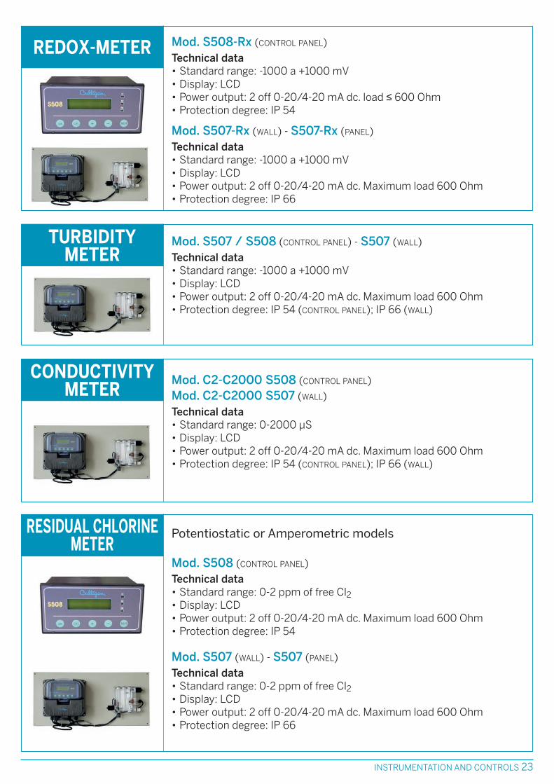
Mod. S508-Rx (CONTROL PANEL)
Technical data• Standard range: -1000 a +1000 mV• Display: LCD• Power output: 2 off 0-20/4-20 mA dc. load ≤ 600 Ohm• Protection degree: IP 54
Mod. S507-Rx (WALL) - S507-Rx (PANEL)
Technical data• Standard range: -1000 a +1000 mV• Display: LCD• Power output: 2 off 0-20/4-20 mA dc. Maximum load 600 Ohm• Protection degree: IP 66
REDOX-METER
Mod. C2-C2000 S508 (CONTROL PANEL)
Mod. C2-C2000 S507 (WALL)
Technical data• Standard range: 0-2000 µS• Display: LCD• Power output: 2 off 0-20/4-20 mA dc. Maximum load 600 Ohm• Protection degree: IP 54 (CONTROL PANEL); IP 66 (WALL)
Mod. S507 / S508 (CONTROL PANEL) - S507 (WALL)
Technical data• Standard range: -1000 a +1000 mV• Display: LCD• Power output: 2 off 0-20/4-20 mA dc. Maximum load 600 Ohm• Protection degree: IP 54 (CONTROL PANEL); IP 66 (WALL)
TURBIDITYMETER
Potentiostatic or Amperometric models
Mod. S508 (CONTROL PANEL)
Technical data• Standard range: 0-2 ppm of free Cl2• Display: LCD• Power output: 2 off 0-20/4-20 mA dc. Maximum load 600 Ohm• Protection degree: IP 54
Mod. S507 (WALL) - S507 (PANEL)
Technical data• Standard range: 0-2 ppm of free Cl2• Display: LCD• Power output: 2 off 0-20/4-20 mA dc. Maximum load 600 Ohm• Protection degree: IP 66
RESIDUAL CHLORINEMETER
CONDUCTIVITYMETER

RW08 remote control via web, with 1.5-m cableTechnical data• Power supply: 230 V 50 Hz• Watertight tank: cam 20x20, 11 cm depth• Protection degree: IP 56
MONITORINGDOSING SYSTEM
24 INSTRUMENTATION AND CONTROLS
MC-10 Control BoardAvailable with amperometric or potenziostatic cellTechnical data• Power supply: 230 Vac ± 10% 50-60 Hz• Operating power: 7 VA max• Display: 2 off alphanumeric LCD displays with 2 lines (16 digits), back-light• Protection degree: IP 65
CONTROL BOARD
Mod. S508 (CONTROL PANEL)Technical data• Standard range: 0,005 - 2 ppm as ClO2; 0,05 - 20 ppm as ClO2• Display: LCD• Power output: 2 off 0-20/4-20 mA dc. Maximum load 600 Ohm• Protection degree: IP 54
Mod. S507 (WALL) - S507 (PANEL)Technical data• Standard range: 0,005 - 2 ppm as ClO2; 0,05 - 20 ppm as ClO2• Display: LCD• Power output: 2 off 0-20/4-20 mA dc. Maximum load 600 Ohm• Protection degree: IP 65
CHLORINE DIOXIDEANALYSER
Chlorine Dioxide DetectorTechnical data• Power supply: 10-30 Vac• Dimensions: 160x122x76 mm• Power output: 4-20 mA• Protection degree: IP 65
DETECTOR
Mod. C500 (CONTROL PANEL)
Technical data• Up to 3 programmable inputs• Up to 6 programmable inputs• Prints on paper• Protection degree: IP 54
RECORDER
INSTRUMENTATION AND CONTROLS 25
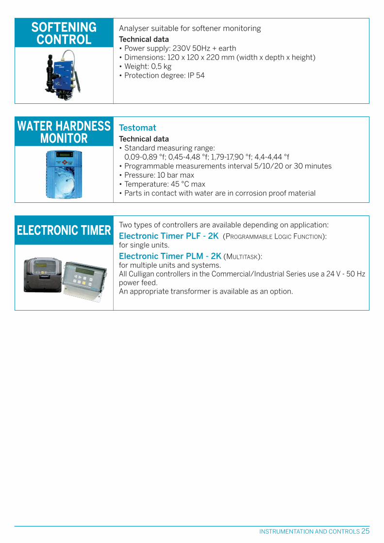
Two types of controllers are available depending on application:
Electronic Timer PLF - 2K (PROGRAMMABLE LOGIC FUNCTION):for single units.
Electronic Timer PLM - 2K (MULTITASK):for multiple units and systems.All Culligan controllers in the Commercial/Industrial Series use a 24 V - 50 Hzpower feed.An appropriate transformer is available as an option.
ELECTRONIC TIMER
Analyser suitable for softener monitoringTechnical data• Power supply: 230V 50Hz + earth• Dimensions: 120 x 120 x 220 mm (width x depth x height)• Weight: 0,5 kg• Protection degree: IP 54
SOFTENINGCONTROL
TestomatTechnical data• Standard measuring range:
0,09-0,89 °f; 0,45-4,48 °f; 1,79-17,90 °f; 4,4-4,44 °f • Programmable measurements interval 5/10/20 or 30 minutes• Pressure: 10 bar max• Temperature: 45 °C max• Parts in contact with water are in corrosion proof material
WATER HARDNESSMONITOR

MODEL MAXIMUM UNIT LAMP WEIGHTFLOW RATE POWER POWER
CONSUMPTION in operation shipping
m3/h V W kg kg
U.V. 20S 4.0 100 2 x 40 19 15
U.V. 40S 11.5 * 210 4 x 40 51 45
U.V. 60S 17.0 * 300 6 x 40 60 52
U.V. 40L 23.0 ** 350 4 x 75 82 75
U.V. 60L 34.0 ** 500 6 x 75 150 102
U.V. 80L 45.5 ** 650 8 x 75 158 110
U.V. 100L 57.0 ** 800 10 x 75 215 132
U.V. 120L 68.5 ** 900 12 x 75 228 145
U.V. 16L 91.5 ** 1200 16 x 65 240 150
U.V. 20L 114.5 ** 1450 20 x 65 336 210
U.V. 24L 137.0 ** 1800 24 x 65 400 250
U.V. 32L 171.0 ** 2300 32 x 65 600 350
U.V. 40L/0 229.0 ** 2900 40 x 65 750 440
U.V. 48L 274.5 ** 3480 48 x 65 950 500
ULTRAVIOLET
* For inlet water with Transmittance T10>96% the dosage is 400 J/m2
** For inlet water with Transmittance T10>94% the dosage is 400 J/m2
Maximum operating pressure 8 bar
Operating temperature room 4-45 °C; water 2-80 °C
Pressure loss at maximum flow rate 0.14 bar for 20S model - 0.2 bar for other models
Power supply 230V - 50/60 Hz
OPERATING DATA
Ultraviolet systems have a high disinfectingcapacity: U.V. rays at 254 nm (nanometer) destroy99.9% of pathogens.They are available in different models, as per tablehere below.Models 40 S, 60 S, and from 40 to 120 L areavailable only with display area.
They are mainly used for point of use disinfectionof sanitary circuits, and as a bacteria preventionon closed circuits. In addition, they are suitable asReverse Osmosis pre-treatment, and whereverdisinfection is necessary, and it is preferred toavoid Chemicals use.
U.V. (ULTRAVIOLET) RAYS ARE GENERATED BY SPECIAL LAMPS EMITTING THE APPROPRIATE
WAVELENGTH OF LIGHT FOR KILLING/INACTIVATING MICROORGANISMS. U.V. TECHNOLOGY IS
OFTEN SELECTED WHEN AN EFFICIENT SYSTEM FOR ELIMINATING PATHOGENS WITHOUT USING
CHEMICALS IS PREFERRED. SOMETIMES U.V. IS USED IN CONJUNCTION WITH OTHER
OXIDANTS/DISINFECTANTS (OZONE, OXYGEN, ETC.) TO INCREASE THEIR EFFECTIVENESS.
MODELS
U.V. STERILIZATION
26 U.V. STERILIZATION

CULLIGAN AERATION TOWERS ARE DESIGNED TO REDUCE, THROUGH FORCED DRAFT AERATION,
THE CONCENTRATION OF DISSOLVED GAS IN WATER. FORCED AERATION OXIDIZES WATER AND
REMOVES GASES SUCH AS METHANE (CH4), CARBON DIOXIDE (CO2) AND HYDROGEN SULFIDE
(H2S). DEGASSERS ARE INSTALLED ABOVE WATER COLLECTING TANKS AND ARE EQUIPPED WITH
A SPECIAL FLANGE FOR EASY INSTALLATION.
Aeration towers models 400, 600, 1000 and 1400are entirely manufactured in polypropylene (PP),while model 1800 is in high grade carbon steel,with a food-grade epoxy resins internal lining and
external corrosion protection using polyurethanepaint.Packing rings for all models are in polypropylene(PP).
Aeration towers are equipped with electric fans thatforce air from the bottom towards the fine waterdroplets falling from the top, thereby separating gasfrom water which is expelled through a vent.
A specially designed device at the base of theaeration tower prevents air from dispersingtowards the water collecting tank.
MATERIALS
OPERATION
The efficiency of aeration towers can be improvedwith the following optional accessories, which areavailable for all models:
• DROP-STOP FILTERS: reduces the amount ofwater carried over by the air stream and areinstalled just prior to the gas outlet.
• SPRAY NOZZLES: designed for maximum waternebulization, are installed on the inlet distributor.
OPTIONAL ACCESSORIES
MODEL CAPACITY* ELECTRIC FAN AIR DIMENSIONS WEIGHT220/380V - 50 Hz - 3 ph FLOW RATE
(1) (2) power max head width depth height in operation shipping
m3/h m3/h kW mm H2O m3/min mm mm mm kg kg
F.D.A. 400 4 10 0.55 ~ 140 13 560 1180 2620 220 110
F.D.A. 600 9 22 1.5 ~ 140 29 780 1475 2620 350 148
F.D.A. 1000 24 60 3 ~ 140 80 1120 1920 2620 1000 335
F.D.A. 1400 50 120 5.5 ~ 140 160 1545 2400 2620 1600 540
F.D.A. 1800 80 200 11 ~ 140 260 1960 2785 3310 3000 1400
* Operating temperature: 5-60 °C • (1) Hydrogen Sulphide and Trihalomethanes (THM’s) • (2) Methane and Carbon Dioxide.
NOTE – Weights are approximate. • Dimensions may vary by ± 2%.
– In addition to the standard models above, aeration towers for larger volumes of water and/or for removingspecific gasses are designed upon request.
AERATION TOWERS
AERATION TOWERS 27

28 MICROFILTRATION
MODEL FLOW RATE CARTRIDGES FITTINGS DIMENSIONS WEIGHT Ø Ø height shipping
withstand*
m3/h no. ” mm mm kg
FGX3
NOTE Operating pressure: 8 barTest pressure: 11.4 bar
FGX3 125 7.5 3 x 500 mm 1 ½ gas 168.3 1115 20
FGX3 150 9 3 x 750 mm 1 ½ gas 168.3 1365 22
FGX3 250 15 3 x 1000 mm 1 ½ gas 168.3 1620 24
FGX3 415 24.9 7 x 750 mm 2 ½ gas 219.1 1371 27
FGX3 580 34.8 7 x 1000 mm 2 ½ gas 219.1 1630 34
FGX3 750 45 9 x 1000 mm 3 gas 273 1780 44
* The figures may change, according to the tripod adjustment.
GARD SYSTEM
NOTE See separate sheets for Gard System technical data.
The diagram shows some out of the many arrangements, which can be obtained with 2, 3 and4 elements.
GARD SYSTEMSingle or multiple filters with ¾”, 1” or 1½” BSPT-Ffittings.A highly versatile modular system, combining filtersinto various configurations (parallel, series, series-parallel, parallel-series) for removal of coarsesuspended solids, activated carbon filters and toprevent corrosion. Gard System cartridges areavailable in the following models:
• STRAINER: with filtration element in washablestainless steel woven wire mesh, for the removal ofsuspended solids up to 10 µm.
• MONOSTAGE or MULTISTAGE: polypropylene food-grade filtering element, for the selective removal ofturbidity.Depending on the type of cartridge used, the filtrationrange varies from 1 to 80 µm.
• IO-CHEM SP12: Crystal phosphate cartridge, forcorrosion prevention.
• CULLAR D: active carbon cartridge, for theabsorption of organics and dechlorination.
FGX3Multiple cartridge filters for medium flow ratesapplications, with AISI 316 stainless steel enclosures,inlet–outlet threaded fittings UNI 338. This systemallows the installation of cartridges of differentfiltration levels (1 - 5 - 20 µm), in standard lengths of10, 20, 30, and 40 inches (250, 500, 750, 1000 mm).Cartridge replacement is easy and rapid thanks to theclamp opening system.The filter is supplied with tripod support for floorinstallation.
MECHANICAL FILTERS ARE A HIGHLY FLEXIBLE, VERSATILE AND ECONOMICAL SOLUTION FOR
ADDRESSING SMALL SCALE WATER FILTRATION PROBLEMS. THEY ARE COMMONLY USED AS
BARRIER AGAINST SUSPENDED SOLIDS FOR PROTECTING SENSITIVE EQUIPMENT.
MODELS
MICROFILTRATION

ULTRAFILTRATION IS A PROCESS OF SEPARATION UNDER PRESSURE, ABLE TO SEPARATEINSOLUBLE PARTICLES FROM WATER AND ABLE TO TOTALLY REMOVE SUSPENDED SOLIDS.THE HEART OF THE ULTRAFILTRATION SYSTEM IS FORMED BY THE MODULES THAT CARRY OUTTHE REAL PROCESS OF SEPARATION: THEY HAVE A HIGH CAPACITY TO WITHHOLD COLLOIDS,SILT, BACTERIA AND MOST VIRUSES.
NOTE Power supply 380 V - 50 Hz 3-phase + earth.
MODEL
ULF 10
ULF 40
ULF 20
ULF 60
ULTRAFILTRATION
Ultrafiltration systems are available in differentmodels, with flow rates from 6 to 112 m3/h. Themodules are made to attain high resistance to
mechanical stress from rubbing and arecomposed of a double layer of hollow fibres(capillaries) made of PVDF.
MODELS
MODULES
No.
1
2
4
6
FLOW RATEmax
m3/h
6
12
24
38
INSTALLEDPOWER
2.2
2.2
3
4
HYDRAULICFITTINGS
DN 40
DN 40
DN 50
DN 65
DIMENSIONS(length x width x height)
mm
1800 x 2150 x 2350
1800 x 2150 x 2350
1800 x 2150 x 2350
2300 x 2150 x 2350
ULF 80
ULF 100
8
10
50
62
4
5.5
DN 80
DN 80
2300 x 2150 x 2350
2750 x 2150 x 2350
ULF 120
ULF 140
12
14
75
87
7.5
7.5
DN 80
DN 80
2750 x 2150 x 2350
3200 x 2150 x 2150
ULF 160
ULF 180
16
18
100
112
11
15
DN 100
DN 100
3200 x 2150 x 2150
3400 x 2150 x 2350
kW
The completely automated system performsscheduled washes during the production cycle.In addition it is equipped with a differentialpressure, able to detect a too high loss of head(caused by the membranes clogging) and to beginthe washing cycle.
The system is fully automated with an electricpanel complete with a PLC, controlling all pumps(metering, washing, etc.) and taking informationfrom pressure and flow measuring instruments.
OPERATION
• Filtering water contaminated by colloids,microbiological impurities and suspended solids
• Production of potable water from surface, springor well water
PRINCIPLE APPLICATIONS
• Pretreatment for Reverse Osmosis systems• Tertiary filtering in waste treatment systems to
obtain water of suitable quality for reuse innon-potable uses
ULTRAFILTRATION 29

30 REVERSE OSMOSIS
The range of standard available R.O. units are listedbelow:
• E1, M1, G1 SERIEScapacity from 40 to 350 l/h
• AQUA-CLEER PROFESSIONAL(designed for dental laboratories) capacity 12 l/h
• AQUA-CLEER SB 200capacity up to 200 l/h
• AQUA-CLEER NFC SERIES(designed for use with industrial dishwashers)capacity 180 l/h
• AQUA-CLEER MFP 4-44 SERIES * capacity from 400 to 3600 l/h
• AQUA-CLEER R.O.2 SERIES*capacity from 400 to 1600 l/h
• AQUA-CLEER SW SERIEScapacity from 300 to 6000 l/h
• AQUA-CLEER IW E & IW L SERIEScapacity from 5000 to 36000 l/h
Compact Systems
• AQUA-CLEER S.D.S.*(for home-based dialysis) capacity from 80 to100 l/h
• PHARMA(for the production of pure water for laboratories)capacity from 35 to 160 l/h
* Models in the MFP 4-44, R.O.2 and S.D.S. range are alsoavailable as “Medical Device”.
NOTE: R.O.2 models are composed by two reverse osmosis units,which are normally operated simultaneously in series (doublepass R.O. or product staging), in emergency the units can beoperated one at the time (single pass R.O.). These units aresuitable for use in hemodialysis and other critical applications.In addition to standard units, it is possible to design customizedunits, for higher flow rates.
REVERSE OSMOSIS (THE ACRONYM R.O. IS COMMONLY USED) IS THE PROCESS OF FORCING
WATER FROM A COMPARTMENT OF HIGH SALT CONCENTRATION THROUGH SEMIPERMEABLE
MEMBRANES TO A COMPARTMENT OF LOWER SALT CONCENTRATION.
OSMOTIC MEMBRANES ARE THE FINEST FILTERS ACTING AS A BARRIER FOR SALTS AND
ORGANICS WITH MOLECULAR WEIGHT ABOVE 100 DALTON, AND ARE AN OUTSTANDING
PROTECTION AGAINST MICRO-POLLUTANTS, PESTICIDES, PYROGENS, VIRUSES AND BACTERIA.
REVERSE OSMOSIS IS A PHYSICAL PROCESS, AND DOES NOT REQUIRE CHEMICALS’ USE.
THE REVERSE OSMOSIS PROCESS IS VERY SIMPLE AND RELIABLE, AND IN RECENT YEARS THE
AVAILABLE MEMBRANES HAVE BEEN DEVELOPED TO GIVE A LOWER ENERGY CONSUMPTION.
MEMBRANES ARE OF HIGH QUALITY AND RELIABILITY, ALSO FOR SPECIFIC WATER APPLICATION.
MODELS
REVERSE OSMOSIS

Hot water DisinfectionSystem
REVERSE OSMOSIS 31
Aqua-Cleer R.O. units are equipped with fullyautomatic control systems for operations andquality control (by means of relevant indicators),and safety.
A number of accessories specifically designed fordialysis are available, meeting current regulatorystandards, including the Discharge Device forartificial kidney, with internal siphon to avoid therise of bacteria from the drain network to thekidney machine.
It is manufactured in AISI Stainless steel and it iscomplete with fast connection.
Hot water production systems are also availablefor thermal sanitization of water distribution loops,as well as cabinets for sound proofing the R.O.units.
Semipermeable membranes are the very heart ofany R.O. unit. Culligan’s Aqua-Cleer systems usespiral wound membranes, selected in accordancewith the characteristics of the water to be treatedand the required capacity.For Sea Water R.O. units, membranes suitable forhigh salinity (up to 45000 ppm) are used.
MATERIALS
OPERATION AND ACCESSORIES
Materials used in fabrication, particularly for partsin contact with water, are food-grade and selectedfor high resistance to corrosion (AISI 316 stainlesssteel, PVC and polyethylene).
Sound proofenclosurefor BI-OMOSISMedical Device
DischargeDevice forartificial kidney
PLC Control Panel

32 REVERSE OSMOSIS
MODEL INSTALLED FITTINGS NOMINAL DIMENSIONS WEIGHT POWER in out FLOW RATE width depth height shipping
feeding product HØ Ø
kW mm mm l/h mm mm mm kg
E1 M1 G1 SERIES
NOTE Weights are approximate. • Dimensions may vary by ± 2%.
R.O. UNITS FOR BRACKISH WATERS
H Average values based on the following standard conditions: water temperature 25 °C;raw water TDS 500 ppm as NaCl; product water pressure 0 bar; new membranes.
For use in applications where high level ofchemical and bacteriological water purity isrequired, and in contrast to traditional deionizationsystems there is no handling or discharge ofhazardous chemicals.
• desalination for potable water production frombrackish or sea water
• pure water for medium to high pressure boilers
• humidifiers
• microchip rinsing for the micro-electronicindustry
• pharmaceutical and cosmetic industry
• textile industry• food production
PRINCIPAL APPLICATIONS
• restaurants, for best dishwasher performance• pre-treatment for boiler deionization system• potable water for ice production• offset printing, to maximise quality and improve
production yield• chemical laboratories, for rinsing instruments
and glassware• floriculture• dialysis applications using “Medical Device”
models, as per UNI CEI EN ISO 13485 Norm,certified to CE0434
• … and in many other applications where purewater is required
E1 Series
M1 Series
G1 Series
E1-1S 0.25 10 10 40 885 312 948 29
E1-2S 0.25 10 10 80 885 312 948 34
E1-3S 0.25 10 10 120 885 312 948 39
E1-2L 0.56 10 10 190 885 312 948 43
E1-3L 0.56 10 10 270 885 312 948 50
E1-4L 0.56 10 10 350 979 312 1090 57
M1-1S 0.25 10 10 40 885 312 948 29
M1-2S 0.25 10 10 80 885 312 948 34
M1-3S 0.25 10 10 120 885 312 948 39
M1-2L 0.56 10 10 190 885 312 948 43
M1-3L 0.56 10 10 270 885 312 948 50
M1-4L 0.56 10 10 350 979 312 1090 57
G1-2S 0.25 10 10 80 955 312 948 35
G1-3S 0.25 10 10 120 955 312 948 40
G1-2L 0.75 10 10 190 955 312 948 44
G1-3L 0.75 10 10 270 955 312 948 51
G1-4L 0.75 10 10 350 1048 312 1090 59
E1 SERIES
M1 SERIES
G1 SERIES

REVERSE OSMOSIS 33
MODEL INSTALLED FITTINGS NOMINAL DIMENSIONS WEIGHT POWER in out FLOW RATE width depth height shipping
feeding product HØ Ø
kW “ “ l/h mm mm mm kg
AQUA-CLEERSB 200
NOTE Weights are approximate. • Dimensions may vary by ± 2%.
H Average values based on the following standard conditions: water temperature 20 °C;raw water TDS 500 ppm as NaCl; product water pressure 0 bar; new membranes.
R.O. UNITS FOR BRACKISH WATERSSB 200 1.5 1 ½ 200 800 650 1600 221
MODEL INSTALLED FITTINGS NOMINAL DIMENSIONS WEIGHT POWER in out FLOW RATE width depth height shipping
feeding product HØ Ø
kW “ “ l/h mm mm mm kg
AQUA-CLEERPROFESSIONAL
NOTE Weights are approximate. • Dimensions may vary by ± 2%.
H Average values based on the following standard conditions: water pressure 6.2 bar with booster pump;water temperature 25 °C; TDS 500 mg/l without counter-pressure with new membrane.
POTABLE WATER SYSTEMProfessional - ¼ ¼ 12 410 310 565 10
NOTE Weights are approximate. • Dimensions may vary by ± 2%.
H Average values based on the following standard conditions: water temperature 20 °C;raw water TDS 500 ppm as NaCl; product water pressure 0 bar; new membranes.
MODEL INSTALLED FITTINGS NOMINAL DIMENSIONS WEIGHT POWER in out FLOW RATE width depth height shipping
feeding product HØ Ø
kW “ “ l/h mm mm mm kg
NFC SERIESR.O. UNITS FOR BRACKISH WATERSNFC 99 0.42 ½ ½ 180 570 460 605 48

34 REVERSE OSMOSIS
MODEL INSTALLED FITTINGS NOMINAL DIMENSIONS WEIGHT POWER in out FLOW RATE width depth height shipping
feeding product HØ Ø
kW “ “ l/h mm mm mm kg
R.O.2
R.O. UNITS FOR PURE WATER PRODUCTIONR.O.2 400 1.5 + 1.5 1 ½ 400 1000 700 1850 220
R.O.2 800 2.2 + 2.2 1 ½ 800 1000 700 1850 260
R.O.2 1200 3 + 3 1 ½ 1200 1000 700 1850 310
R.O.2 1600 4 + 4 1 ½ 1600 1000 700 1850 350
MODEL INSTALLED FITTINGS NOMINAL DIMENSIONS WEIGHT POWER in out FLOW RATE width depth height shipping
feeding product HØ Ø
kW “ “ l/h mm mm mm kgkg
SWSEA WATER R.O. UNITSSW 300 5.5 1 ½ 300
SW 600 5.5 1 ½ 600
SW 900 15 1 ½ ¾ 900
SW 1500 18.5 1 ½ 1 1500
SW 2000 18.5 1 ½ 1 2000
SW 3000 37 2 1 ½ 3000
SW 4000 45 2 ½ 1 ½ 4000
SW 6000 55 2 ½ 1 ½ 6000
NOTE Weights are approximate. • Dimensions may vary by ± 2%.
H Average values based on the following standard conditions: water temperature 20 °C;raw water TDS 500 ppm as NaCl; product water pressure 0 bar; new membranes.
NOTE Weights are approximate. • Dimensions may vary by ± 2%.
H Average values based on the following standard conditions: water temperature 20 °C;raw water TDS 500 ppm as NaCl; product water pressure 0 bar; new membranes.
MFP 4-44
NOTE Weights are approximate. • Dimensions may vary by ± 2%.
H Average values based on the following standard conditions: water temperature 20 °C;operating pressure 200 or 261 psi (14 or 18 bar); recovery ratio 75%; raw water TDS 500 ppm as NaCl;product water pressure 0 bar; new membranes.
MODEL INSTALLED FITTINGS NOMINAL DIMENSIONS WEIGHT POWER in out FLOW RATE width depth height shipping
feeding product HØ Ø
kW “ “ l/h mm mm mm kg
R.O. UNITS FOR BRACKISH WATERS400 1.5 1 ½ 400 500 660 1550 115
800 1.5 1 ½ 800 500 660 1550 140
1200 2.2 1 ½ 1200 500 660 1550 170
1600 2.2 1 ½ 1600 500 660 1550 190
2200 4 1 ¾ 2000 500 660 1800 220
2800 4 1 ¾ 2400 500 660 1800 250
3300 4 1 ¾ 2800 500 660 1800 280
3600 4 1 ¾ 3200 500 770 1800 280
4000 4 1 ¾ 3600 500 770 1800 280
CHANGES ACCORDING
TO CONFIGURATION

REVERSE OSMOSIS 35
MODEL INSTALLED FITTINGS NOMINAL DIMENSIONS WEIGHT POWER in out FLOW RATE width depth height shipping
feeding productØ Ø
kW mm mm l/h mm mm mm kg
S.D.S.
MODEL INSTALLED FITTINGS NOMINAL DIMENSIONS WEIGHT POWER in out FLOW RATE width depth height shipping
feeding productØ Ø
kW mm mm l/h mm mm mm kg
PHARMA
NOTE Weights are approximate. • Dimensions may vary by ± 2%.
NOTE Weights are approximate. • Dimensions may vary by ± 2%.
R.O. UNIT FOR HOME-BASED DIALYSISS.D.S. 0.39 8 6 80-100 375 365 900 50
PURE WATER FOR LABORATORIESPharma 20 0.25 10 6 35 380 440 920 80
Pharma 45 0.42 12 8 80 500 500 1450 123
Pharma 80 0.42 12 8 120 500 500 1450 130
Pharma 120 0.42 12 8 160 500 500 1450 140
MODEL INSTALLED FITTINGS NOMINAL DIMENSIONS WEIGHT POWER in out FLOW RATE width depth height shipping
feeding product HØ Ø
kW “ “ l/h mm mm mm kg
IW E • IW LR.O. UNITS FOR BRACKISH WATERSIW E/L 5 7.5 2 1 ½ 5000 4850 1200 1700 650
IW E/L 8 7.5 2 2 8000 3850 1200 1700 710
IW E/L 12 11 2 2 12000 3850 1200 1700 950
IW E/L 16 11 2 2 16000 4850 1200 2100 1280
IW E/L 20 15 3 2 20000 6850 1200 2100 1370
IW E/L 23 15 3 2 23000 6850 1200 2100 1600
IW E/L 26 18.5 3 2 ½ 26000 4850 1200 2250 1850
IW E/L 30 22 3 2 ½ 30000 6850 1200 2250 2100
IW E/L 36 22 3 2 ½ 36000 6850 1200 2250 2100
NOTE Weights are approximate. • Dimensions may vary by ± 2%.
H Average values based on the following standard conditions: water temperature 20 °C;raw water TDS 1500 ppm as NaCl; product water pressure 0 bar; new membranes.

OPERATING DATA
In hospitals it is often necessary to installequipment quickly and within limited space.Dual Box is the answer: a packaged systemhoused in two steel free standing industrialenclosures, containing pre-treatment and Bi-Osmosis units, fully pre-assembled with allconnections and hydraulic and electronic controls.
DUAL BOX
These systems are “plug and play”, you only needto connect water inlet, outlet and drain and powersupply.Bi-Osmosis units are equipped with PLC controlpanel, for managing all operational functions.Enclosures are lockable for complete security.
36 REVERSE OSMOSIS
E1 - M1 - G1 SERIESAQUA-CLEER PROFESSIONAL
AQUA-CLEER SB 200NFC SERIES
Minimum inlet water pressure
E1 - M1 - G1 Series: 1.4 bar
Aqua-Cleer Professional: 2.8 bar
Aqua-Cleer SB 200: 2 bar
NFC Series: 1 bar
2 bar
MFP 4-44 / R.O.2 / SWIW E / IW L
S.D.S. / PHARMA
S.D.S.: 1 bar
Pharma: 1.5 bar
Operating pressure
Aqua-Cleer Professional: 6.2 bar
Aqua-Cleer SB 200: 13 bar
NFC Series: 12 bar
MFP e R.O.2: 14 bar up to 1600 model
18 bar for other models
SW: > 35 bar - IW E / IW L: 14 bar
S.D.S.: 1 bar
Pharma: 1.5 bar
Power supply
E1 - M1 - G1 Series: 230 V - 50 Hz
Aqua-Cleer Professional: 24/230 V - 50 Hz
Aqua-Cleer SB 200: 380 V - 50 Hz
NFC Series: 24/230/110 V - 50 Hz
380 V - 50 Hz 380 V - 50 Hz
TDS (maximum salinity as NaCl) 500 ppm3000 ppm up to 1600 model
1500 ppm for other models1500 ppm
E1 - M1 - G1 Series: 40-50%
Aqua-Cleer Professional: 25%
Aqua-Cleer SB 200: 75%
NFC Series: 20-60%
75% max
S.D.S.: 50%
Pharma 20: 20-25%
Pharma 45-80-120: 20-30%
Recovery ratio
Operating pressure for
membranes’ feedingE1 - M1 - G1 Series: 10.5 bar - -

DEMINERALIZATION 37
The “continuous Electrodeionization” is the latestaddition to the Culligan range. EDI produces highquality water with no need for regenerants, suchas acid and caustic, typical of demineralizationsystems with ion exchange resins.
To attain the ultra-high quality standards, the EDIsystem uses electricity, selective membranes andion exchange resins.
DEMINERALIZATION (OR DEIONIZATION) IS A PROCESS MEANT TO REMOVE SALTS FROM WATER
THROUGH ION EXCHANGE RESIN.
WATER IS PASSED THROUGH CATION AND ANION RESIN, EITHER SEPARATE OR MIXED TOGETHER.
POSITIVELY CHARGED IONS (CATIONS) AND NEGATIVELY CHARGED IONS (ANIONS) ARE
RETAINED BY CATION RESIN AND ANION RESIN RESPECTIVELY.
ONCE RESIN BECOMES SATURATED WITH RETAINED SALTS, REGENERATION WITH
HYDROCHLORIC ACID AND SODIUM HYDROXIDE IS NECESSARY TO RESTORE THE EXCHANGE
CAPACITY.
Electrodeionization is a technology for theproduction, without using chemicals products, ofultrapure water, thanks to the combined use ofspiral-wound membranes and ion-exchangeresins. A continuous electric current source is connectedto an anode and a cathode which keeps the resinactivated and, thanks to the magnetic field
between anode and cathode, improves the waterelectrolysis and the separation of the dissolvedions.Thanks to this process is possible to produce highpurity water (18 MOhms) starting from waterwhich has been already demineralized by adouble-pass reverse osmosis system or a doubleresins bed.
The construction materials used and especiallythose of the parts in contact with the water are allof proven resistance to corrosion and do not giverise to any phenomena of transfer.
MATERIALS
OPERATION
DEMINERALIZATION
The models in the EDI Culligan line are designedand made according to the highest standards ofquality, safety and silence.
The EDI has a general electrical panel completewith PLC so it is independently managed.
The brine injection system, complete with tankand recirculation pump with the front panelcomplete with flow rate and pressure gauges,makes the system complete and compact.
MODELS
EDI

38 DEMINERALIZATION
• Electronic
• High pressure boiler
• Painting
• Printing
PRINCIPAL APPLICATIONS• Preparation and dilution of liquors
• Pharmaceutical
• Cosmetic
• Make-up water
The “portable Electrodeionization” line includessmall ion exchange demineralization systems of
easy maintenance, and makes use of resin notsuitable for on-site regeneration.
Culligan deionizers are fully automatic, withprogrammable service, and regeneration cycles.D and MB Deionizers can be connected to thewater supply via flexible hoses included in thepackaging.A monitoring device will indicate when resin isexhausted. Regeneration is carried out in Culliganpremises.Pharma has been conceived with criteria ofrationality and simplicity: given that the system isto be fed with potable water, and using, in the re-finishing phase, «single-use» resins, since theyoffer better exchange characteristics compared tonormal regenerative resins, and they eliminate the
bother and costs associated with handling thecontainers for periodic regeneration.A device for partial recycling and timing providesfor continuous or intermittent use, alwaysmaintaining the quality of product water at thehighest levels.A second timer signals, with an acoustical andvisual alarm, when it is advisable to replace thepre-filtration cartridges.The quality of product water is constantlymonitored by a conductivity meter, which can testeither the purity of the treated water or of theosmotic water.
Resin vessels in the Deionizer Serie D and MB aremanufactured in fiberglass.MB fiberglass vessels are protected by externalABS jacket.Refill Line vessels are available in stainless steel orPVC.
MATERIALS
OPERATION
Pharma is a compact system, with characteristicsof safety, compactness, transportability andquietness. All the hydraulic components arecorrosion proof, and suitable for food and medicaluse. They have designed to withstand, by a largemargin, the normal operation of the system.
These standard models are available:
• Deionizer D 25 P, MB 9 and MB 16, mixed bedportable exchange.
• Refill Line, high-capacity single-use mixed bedresin cartridge ideal for low volume applications.
• Pharma for ultrapure water production, for thespecific requirements of analyses’ laboratories.
MODELS
• Pharmaceutical
• Cosmetic
• High pressure boiler
PRINCIPAL APPLICATIONS• Laboratories
• Printing
• Preparation and dilution of liquors
PEDI

Demineralization automatic systems are oftenincluded in Culligan Matrix Solutions proposals,when great volume of high quality water isrequested.
Culligan on-site regenerable deionizers are fullyautomatic, with programmable service, andregeneration cycles.DS Deionizers are equipped with two automaticvalves (one per column) and one common controlpanel.
Deyolit series Deionizers are equipped with acontrol panel (including conductivity meter)designed to monitor the process andautomatically initiate regeneration when waterquality deteriorates beyond a pre-determinedlimit.
Resin vessels in the Deionizer DS line aremanufactured in fiberglass.Deyolit resin vessels are manufactured in highgrade carbon steel, internally coated in ebonite
MATERIALS
OPERATION
(hard rubber) and externally painted with corrosionproof paint. Valves in Noryl and piping in PVC areideally suited to withstand extreme pH conditions.
• Deionizer DS separate exchange columns (cationand anion), with automatic on-site resinregeneration.
• Deyolit NRC, separate exchange columns andcounter-current regeneration, for high qualitywater and low regenerant consumption.
• Deyolit AMB, mixed bed unit, for completeremoval of salts from water (ideal for polishingwater already treated by separate two beddeionizers or RO units).
MODELS
• Electronic
• High pressure boiler
• Printing
• Preparation and dilution of liquors
• Food and beverage
PRINCIPAL APPLICATIONS• Painting
• Pharmaceutical
• Cosmetic
• Product water
• Water-jet cut
AUTOMATIC DEMINERALIZATION
DEMINERALIZATION 39
NOTE Dimensions may vary by ± 2%.
MODEL
EDI 10
EDI 30
EDI 20
EDI 40
MODULES
No.
1
2
3
4
FLOWRATEmax
m3/h
2.2
4.5
6.5
9
DIMENSIONS(length x width x height)
mm
1700 x 1200 x 1500
1700 x 1200 x 1500
1700 x 1200 x 1500
1700 x 1550 x 1500
EDI 60 6 13 1700 x 1550 x 1500
EDIPOWER
kW
2
3.5
5
7
10
HYDRAULIC FITTINGS
1½”
2”
2”
2”
2”
Supply
1”
1”
1”
1½”
1½”
Product
tube Ø 6
tube Ø 6
tube Ø 6
tube Ø 6
tube Ø 6
Electrolyte
1”
1”
1”
1”
1”
Concentrate
MODEL EXCHANGE SERVICE FITTINGS DIMENSIONS WEIGHT CAPACITY FLOW RATE in/out Ø height in operation shippingPER CICLE Ø
kg (CaCO3) l/min. ” mm mm kg kg
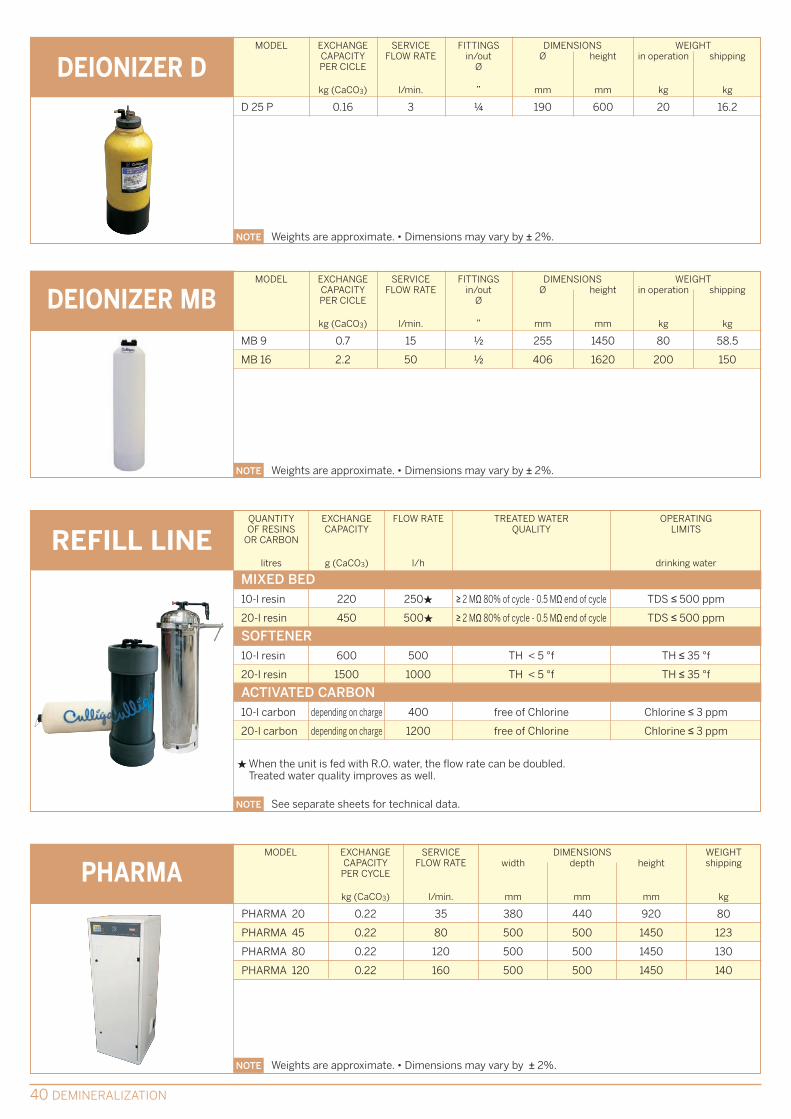
DEIONIZER D
NOTE Weights are approximate. • Dimensions may vary by ± 2%.
D 25 P 0.16 3 ¼ 190 600 20 16.2
MODEL EXCHANGE SERVICE FITTINGS DIMENSIONS WEIGHT CAPACITY FLOW RATE in/out Ø height in operation shippingPER CICLE Ø
kg (CaCO3) l/min. ” mm mm kg kg
DEIONIZER MB
NOTE Weights are approximate. • Dimensions may vary by ± 2%.
MB 9 0.7 15 ½ 255 1450 80 58.5
MB 16 2.2 50 ½ 406 1620 200 150
PHARMA
NOTE Weights are approximate. • Dimensions may vary by ± 2%.
REFILL LINEMIXED BED10-l resin 220 250H ≥ 2 MΩ 80% of cycle - 0.5 MΩ end of cycle TDS ≤ 500 ppm
20-l resin 450 500H ≥ 2 MΩ 80% of cycle - 0.5 MΩ end of cycle TDS ≤ 500 ppm
SOFTENER10-l resin 600 500 TH < 5 °f TH ≤ 35 °f
20-l resin 1500 1000 TH < 5 °f TH ≤ 35 °f
ACTIVATED CARBON10-l carbon depending on charge 400 free of Chlorine Chlorine ≤ 3 ppm
20-l carbon depending on charge 1200 free of Chlorine Chlorine ≤ 3 ppm
QUANTITY EXCHANGE FLOW RATE TREATED WATER OPERATINGOF RESINS CAPACITY QUALITY LIMITS
OR CARBON
litres g (CaCO3) l/h drinking water
HWhen the unit is fed with R.O. water, the flow rate can be doubled.Treated water quality improves as well.
NOTE See separate sheets for technical data.
PHARMA 20
MODEL
kg (CaCO3)
EXCHANGECAPACITY
PER CYCLE
0.22
PHARMA 45 0.22
PHARMA 80 0.22
PHARMA 120 0.22
l/min.
SERVICEFLOW RATE
35
80
120
160
mm
DIMENSIONS
380
500
500
500
mm
440
500
500
500
mm
920
1450
1450
1450
width depth height
kg
WEIGHTshipping
80
123
130
140
40 DEMINERALIZATION

OPERATING DATA
MODEL EXCHANGE SERVICE FITTINGS DIMENSIONS WEIGHT CAPACITY FLOW RATE in/out width depth height in operation shipping
PER CYCLE Ø
kg (CaCO3) m3/h ” mm mm mm kg kg
DEYOLIT NRCNRC 12/12 12 6.5 2 2000 1000 2950 1625 1300
NRC 20/20 20 11 2 2100 1100 3000 3063 2450
NRC 30/30 30 16 2 2280 1270 3050 4500 3600
NRC 50/50 50 23 2 2480 1470 3100 7000 5600
NRC 80/80 80 40 2 ½ 2980 1720 3250 10500 8400
MODEL EXCHANGE RAW D.I. FITTINGS DIMENSIONS WEIGHT CAPACITY WATER WATER in/out width depth height in operation shipping
PER CYCLE FLOW RATE FLOW RATE Ø
kg (CaCO3) m3/h m3/h ” mm mm mm kg kg
DEYOLIT AMBAMB 3000 3 3.4 7.9 1 ½ 830 750 2710 600 350
AMB 5000 5 4.5 10.9 2 1000 850 2800 700 400
AMB 7500 7.5 6.8 15.9 2 1000 1000 3200 880 500
NOTE Weights are approximate. • Dimensions may vary by ± 2%.
NOTE Weights are approximate. • Dimensions may vary by ± 2%.
MODEL EXCHANGE SERVICE FITTINGS DIMENSIONS WEIGHT CAPACITY FLOW RATE in/out width depth height in operation shipping
PER CYCLE Ø
kg (CaCO3) m3/h ” mm mm mm kg kg
DEIONIZER DS
NOTE Weights are approximate. • Dimensions may vary by ± 2%.
DS 50 2 1.6 1 2400 680 1600 300 154
DS 100 4 2.5 1 2450 785 1850 520 300
DS 200 6.5 3.4 1 2450 785 1850 750 450
DEMINERALIZATION 41
D 25 P - MB 9-16
Minimum operating pressure
Maximum operating pressure
Operating temperature
Power supply
Installed power
2 bar
7 bar
4-35 °C
230 V - 50 Hz
-
EDI
2.5 bar
4.1 bar
10-38 °C
230 V - 50 Hz
-
DS
2.8 bar
5.5 bar
5-40 °C
230/24 V - 50/60 Hz
3-35 W
NRC
3 bar
5 bar
5-40 °C
230 V - 50 Hz
50 W
AMB
2 bar
5 bar
3-35 °C
230 V - 50 Hz
250 W

42 DISINFECTION
Besides U.V. Sterilization (already specified in thiscatalogue, in the pre-treatment product section), itis possible to carry out sanitization treatmentswith specific Culligan products (to name some
common examples: Sodium hypochlorite, Calciumhypochlorite, hydrogen peroxide, peracetic acid,etc...), chlorination and ozonation treatments.
Chlorine is the most cost effective and widely useddisinfectant, is readily available around the world(it can be generated on-site, if required), andmaintains permanent water disinfection.
Ozone is an inconstant gas which, in contact withwater, splits and release activated oxygen. It mustbe generated on site and has no permanent effect.
DISINFECTION
Chlorine Dioxide is also widely used as disinfectantfor potable water. It is generated on-site indedicated reactors, by mixing Hydrochloric Acid(HCl) and Sodium Chlorite (Na ClO2) inappropriate proportion. Chlorine Dioxide iseffective over a wide range of pH (4-10), ascompared to other Chlorine based compounds,which are not effective for pH values above 7.5.
Dosing can be controlled either manually, or incombination with proportional pulse emitters, orusing specific analysis control boards by 4-20 mAsignal.
In addition to CHLORINE DIOXIDE GENERATORS(available as CDP and ClO2 Series), the followingaccessories are available for the correct managingof the unit: online analyzer (to determine correctdosing), sensor for gas leakage alarm and safetyeye wash fountain.
In order to be able to expand to civil users (suchas hospitals, clinics, hotels, schools, etc.) the samebenefits granted by Chlorine Dioxide to municipalwater supply, Culligan has completed its range ofproducts by introducing Chem Oxide.
Chem Oxide is a new disinfecting product, able togenerate a Chlorine Dioxide solution of puritygreater than 99.9% into a liquid solution withconcentration to 0.3%. This method differs fromthe traditional Chlorine Dioxide production as it is
no longer necessity of a reactor for the production.Moreover, Chem Oxide avoid almost completelythe formation of byproducts (such as Chloratesand Chlorites) and has a long half-life kinetictiming.
DISINFECTION IS NOT ONLY DOSING CHEMICALS, BUT RATHER SELECT A “SYSTEM” ANDINTEGRATE IT INSIDE EVERY SPECIFIC WATER TREATMENT: FOR A PROPER SELECTION OF THEBEST DISINFECTION IT IS INDEED NECESSARY TO EXAMINE THE ENTIRE WATER TREATMENTPROCESS, TO SELECT THE PRODUCT TO BE USED, DEFINE DOSING APPLICATION; SKILLEDTECHNICIANS WILL SELECT THE RIGHT UNITS TO BE USED. CULLIGAN MATRIX SOLUTIONSDISINFECTION SYSTEMS KEEP THE QUALITY OF TREATED WATER IN THE DISTRIBUTION CIRCUIT,AND TO THE POINT OF USE FOR SPECIFIC APPLICATIONS.
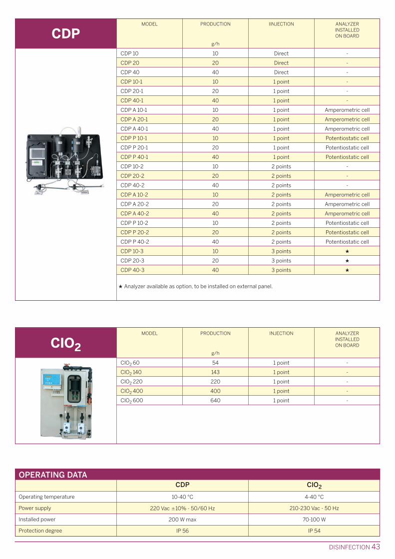
DISINFECTION 43
CDP
OPERATING DATA
MODEL
CDP 10
PRODUCTION
g/h
IINJECTION ANALYZERINSTALLEDON BOARD
10 Direct -
CDP 20 20 Direct -
CDP 40 40 Direct -
CDP 10-1 10 1 point -
CDP 20-1 20 1 point -
CDP 40-1 40 1 point -
CDP A 10-1 10 1 point Amperometric cell
CDP A 20-1 20 1 point Amperometric cell
CDP A 40-1 40 1 point Amperometric cell
CDP P 10-1 10 1 point Potentiostatic cell
CDP P 20-1 20 1 point Potentiostatic cell
CDP P 40-1 40 1 point Potentiostatic cell
CDP 10-2 10 2 points -
CDP 20-2 20 2 points -
CDP 40-2 40 2 points -
CDP A 10-2 10 2 points Amperometric cell
CDP A 20-2 20 2 points Amperometric cell
CDP A 40-2 40 2 points Amperometric cell
CDP P 10-2 10 2 points Potentiostatic cell
CDP P 20-2 20 2 points Potentiostatic cell
CDP P 40-2 40 2 points Potentiostatic cell
CDP 10-3 10 3 points H
CDP 20-3 20 3 points H
CDP 40-3 40 3 points H
H Analyzer available as option, to be installed on external panel.
ClO2
MODEL PRODUCTION
g/h
INJECTION ANALYZERINSTALLEDON BOARD
ClO2 60
ClO2 140
ClO2 220
ClO2 400
ClO2 600
54 1 point -
143 1 point -
220 1 point -
400 1 point -
640 1 point -
CDP
Operating temperature 10-40 °C
Power supply 220 Vac ±10% - 50/60 Hz
Installed power 200 W max
Protection degree IP 56
ClO2
4-40 °C
210-230 Vac - 50 Hz
70-100 W
IP 54

44 WASTE WATER
Duplox: the purification systems of this line aredesigned for the treatment of residentialwastewater polluted by biodegradable organicsubstances. Culligan offers four different basic models, to servecommunities with 60 to 250 inhabitants. The size
of each unit depends on "population-equivalent".OFSY-WGR: a system consisting of two filter unitsarranged in series. Available in five models in theversion with threaded connections, and fourmodels in the version with flanged connections.
A COMPLETE TREATMENT SOLUTION MUST TAKE INTO ACCOUNT THE POSSIBILITY OF REDUCING
WATER CONSUMPTION THROUGH THE REUSE AND RECYCLING OF WASTEWATER. LESS WASTE
MEANS BETTER EFFICIENCY, REDUCED COSTS AND LOWER ENVIRONMENTAL IMPACT.
CULLIGAN OFFERS WATER RECOVERY, RECYCLING AND REUSE SOLUTIONS, FOR "MORE MENIAL"
USES OF THIS IMPORTANT RESOURCE: RECYCLED WATER IS GOOD FOR IRRIGATION, AND FOR A
NUMBER OF TECHNOLOGICAL USES IN THE INDUSTRIAL CONTEXT (COOLING SYSTEMS, FIRE-
EXTINGUISHING SYSTEMS, INDUSTRIAL WASHING, ETC.).
MODELS
WASTE WATER
The Duplox mainly consists of a tank, in which thewastewater undergoes intense aeration, with staytimes of about 20 hours. Aeration occurs byblowing compressed air supplied by an electricblower. A submersible pump transfers the treatedwater to the outlet. All the equipment outside thetank is located in a galvanized steel cabin.
The filters making up the OFSY-WGR system are insteel, with corrosion protection consisting of athick inner coating (250-300 µ) of specific epoxyresins and an outer coating of 80-100 µ.
MATERIALS
The Duplox works according to two differentsystem principles: by repetition of cycles orcontinuous flow.The biological treatment concentrates in shorttimes and in small amounts the treatmentprocesses carried out in nature by microorganisms.The biological system can be considered as the"breeding" of microorganisms that reproduce usingthe atmospheric oxygen dissolved in the water.Organic pollution is expressed as BOD. Themicroorganisms are separated from the treatedwater and recirculated in the water to be purified.
The Omnifiltration system (OFSY-WGR) consists oftwo filter units arranged in series, whose operationis regulated by 8 diaphragm valves, activated byan electronic control unit and by a pilot distributorthat controls opening and closing, implementingthe service and washing phases.During the service phase, the water to be filteredpasses downward through the filtering mineralsand flows out free of unwanted elements.When a certain loss of pressure is reached, thefilter is backwashed and rinsed using untreatedwater.
OPERATION

WASTE WATER 45
DUPLOX
NOTE Weights are approximate. • Dimensions may vary by ± 2%.
MODELper day
max
m3/h
DC 6
FLOW RATEper hour
max
m3/h
POPULATIONEQUIVALENT
No. BOD5 kg/day
ORGANICLOAD
DIMENSIONStank
Ø
mm mm mm
totallength
heightmax
WEIGHTin
operationshipping
kg kg
12 1.7 60 2.7-5.4 2100 5580 3800 19000 2500
DC 12 24 3 120 4.7-9.4 2100 8580 3800 28000 2800
DC 20 40 4.9 200 7.8-14 2500 10000 4200 46000 3200
DC 25 50 6 250 7.8-14 2500 12000 4200 60000 4000
BOD: Biochemical oxygen request
OFSY-WGRMODEL FLOW RATE FITTINGS DIMENSIONS WEIGHT
service backwash in / out width depth height in shippingmax Ø operation
m3/h m3/h mm mm mm kg kg
NOTE Weights are approximate. • Dimensions may vary by ± 2%.
OFSY 20 WGR 2.5 9.1 1 ½” 1100 880 1960 1230 960
OFSY 24 WGR 3.4 13.6 1 ½” 1200 980 2000 1720 1300
OFSY 30 WGR 6.1 20.4 1 ½” 1600 1130 2050 2720 2010
OFSY 36 WGR 9.1 40.9 2 ½” 2010 1480 2130 4150 3200
OFSY 48 WGR 15.9 56 2 ½” 2500 1730 2235 7450 5250
OFSY 60 WGR 24.9 79.3 DN 80 3200 1760 2150 10500 7200
OFSY 72 WGR 34 118 DN 100 3750 2150 2150 15000 10500
OFSY 84 WGR 50 159 DN 100 4350 2450 2160 20000 14000
OFSY 100 WGR 68.1 225 DN 150 5200 2950 2370 29500 21000
OPERATING DATADUPLOX
Minimum operating pressure -
Maximum operating pressure -
Operating temperature -
Power supply 380 V - 50 Hz
OFSY-WGR
1.8 bar
7 bar up to model 60” - 5 bar for the larger models
5 - 50 °C
110/230/24 V - 50/60 Hz
Installed power 2.2 - 4.6 W 10 W
Pressure loss - 0.6 bar

Culligan is a world leader in global watertreatment solutions. We offer a highly professionaland reliable after-sales service.The integrated service consists of installation,commissioning, chemicals, contracts for standardmaintenance and extraordinary interventions: allthis is all-important in order to offer ourcustomers a global solution.We operate in over 90 countries worldwide, withmore than 800 dealers and licensees.In Italy we are present nationwide, with 12branches and 94 authorized distributors. Over300 specialized technicians are available, to meetall the needs of our customers in the shortestpossible time.
Culligan technicians can service all the watertreatment systems: we offer a range of servicesolutions designed to meet the individual needs ofcustomers.Culligan technicians are highly experienced, inhaving worked on many types of water treatmentsystems in various sectors:
Offshore plants and platforms•Power stations•Systems for the pharmaceutical sector•Systems for the marine sector (naval and•commercial)Manufacture of semiconductors•Systems for the food industry•
We can also to offer customers fixed prices formulti-year assistance contracts, for long-termplanning.
The Service Culligan offers a wide range ofservices, including:
Installation and commissioning•Maintenance contracts•System performance monitoring and reports•Chemical cleaning of RO membranes•Upgrading / renewal of existing equipment•Trouble shooting•
Energy efficiency improvement•Improvement of system performance•Reduced OPEX costs•
All Culligan spare parts for our systems areavailable through the customer service network.
For standard items our warehouse, supported byadvanced logistics, carries out prompt deliveriesnationwide and abroad.
Original spare parts ensure perfect operation.They are more than just "new for old", and cansignificantly improve the performance of yoursystem.
Our spare parts are designed to prolong the life ofthe components and reduce maintenance costs.
Furthermore, the Culligan Service program alsoprovides for the supply of a wide and innovativerange of chemicals for technological use, toensure a qualified choice of applications.
Ongoing research and the direct experienceacquired have enabled Culligan to flank the line oftreatment systems with a wide range of chemicalsfor water conditioning.
The current regulations recommend watertreatment using suitable equipment (filters, watersofteners, deionizers) and integrating thetreatment with appropriate chemical conditioning.
The above allows the formulation of proposals thatdo not prioritize system or chemical conditioningcriteria, but globally meet the user's technical andregulatory requirements, even in the subsequentmanagement phase.
ASK THE CULLIGAN EXPERT FOR DETAILSREGARDING THE APPLICABLE SERVICESOLUTIONS.
SERVICE
46 SERVICE
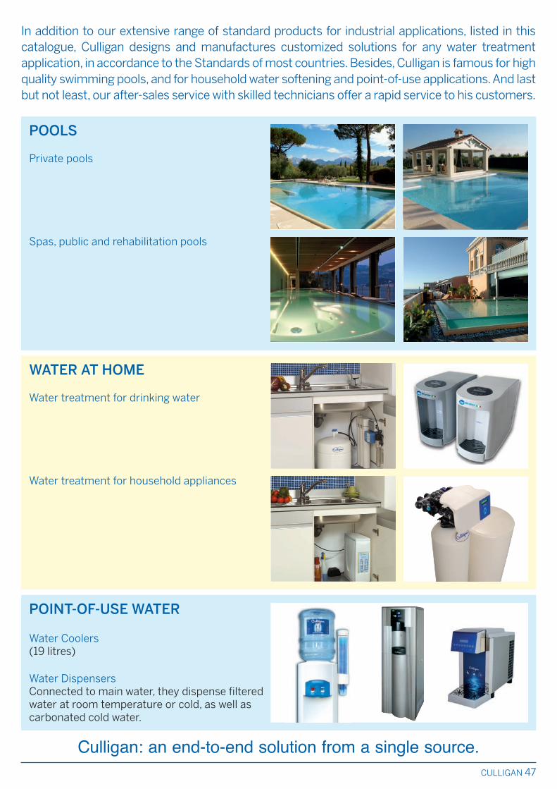
CULLIGAN 47
WATER AT HOME
Water treatment for drinking water
Water treatment for household appliances
POINT-OF-USE WATER
Water Coolers (19 litres)
Water DispensersConnected to main water, they dispense filteredwater at room temperature or cold, as well ascarbonated cold water.
POOLS
Private pools
Spas, public and rehabilitation pools
In addition to our extensive range of standard products for industrial applications, listed in thiscatalogue, Culligan designs and manufactures customized solutions for any water treatmentapplication, in accordance to the Standards of most countries. Besides, Culligan is famous for highquality swimming pools, and for household water softening and point-of-use applications. And lastbut not least, our after-sales service with skilled technicians offer a rapid service to his customers.
Culligan: an end-to-end solution from a single source.

Culligan Warranty: defects in manufacturing are covered by the Culligan Warranty Policy.Culligan reserves the right to change thespecifications referred to in this literature
at any time, without prior notice.
QUALITY SYSTEM CERTIFIED ACCORDING TO UNI EN ISO 9001:2008 NORM
Cat
. No.
BU
018
6/0
9-2
013
WORLDWIDE PRESENCE, EITHER WITH DIRECT SUBSIDIARIESOR VIA LOCAL INDEPENDENT DEALERS, WITH SKILLED ENGINEERS TO
HELP YOU IN SOLVING ANY WATER TREATMENT PROBLEMAND SPARE PARTS STORAGE TO KEEP YOU GOING.
MANUFACTURING HEADQUARTERS:
U.S.A. • CULLIGAN INTERNATIONAL Co.9399 West Higgins Road - Suite 1100 - ROSEMONT, IL 60018Tel. + 1 847.4302800 - Fax + 1 847.4301519 - www.culligan.com
ITALY • CULLIGAN ITALIANA SpAVia Gandolfi, 6 - 40057 CADRIANO di Granarolo dell’Emilia (BO)Tel. + 39 051.6017111 - Fax + 39 051.765602 - www.culligan.it
COMMERCIAL OFFICES:
BELGIUM • CULLIGAN N.V.P. Gilsonlaan 45-49 - 1601 RUISBROEKTel. + 32 2.3777707 - Fax + 32 2.3770312 - www.culligan.be
FRANCE • CULLIGAN FRANCE S.A.4, rue des Charmes - ZA du Buisson de la Couldre - 78190 TRAPPESTel. + 33 1.30162323 - Fax + 33 1.30162356 - www.culligan.fr
SPAIN • CULLIGAN ESPANA S.A.C/ Trepadella 12 - 08755 CASTELLBISBAL (Barcelona)Tel. + 34 93.5653300 - Fax + 34 93.5653309 - www.culligan.es
TURKEY • CULLIGAN TRC A.S.Alemdag St. No.52 - 34692 Uskudar - ISTANBULTel. + 90 216.4411047 - Fax + 90 216.4428479 - www.culligan.com.tr
UNITED KINGDOM • CULLIGAN (UK) LtdCulligan House - The Gateway Centre, Coronation RoadHIGH WYCOMBE - Buckinghamshire HP12 3SUTel. + 44 1494.441286www.culligan.co.uk
U.A.E. • CULLIGAN INTERNATIONAL (EMIRATES) LLCP.O. Box 37728 - Al Quoz Industrial Area, DubaiTel. + 971 4.3389880 - Fax + 971 4.3389881P.O. Box 129054 - Abu Dhabi Tel. + 971 2.6667140 - Fax + 971 2.6667141www.culligan.com
CHINA • CULLIGAN INTERNATIONAL CHINAShanghai Jjahua Business Center A3 - Room 3302808 Hongqiao Road - SHANGHAI 200030 Tel. + 86 21.64479680 - Fax + 86 21.64479937 - www.culligan.com
www.culliganmatrixsolutions.it
CULLIGAN ITALIANA [email protected] • www.culliganmatrixsolutions.it
Recommended