Visibility Chain at Regional Airports in the Netherlands
Wiel Wauben
R&D Information and Observation Technology
TECO 2012 | Visibility Chain2
Introduction
• KNMI automated the aeronautical observations at regional civil
airports, the so-called AUTO METAR system.
• During the evaluation many questions related to visibility arose.
• It was realized that documentation was scattered between
departments and incomplete; not always verified against current
practices or ICAO requirements and recommendations;
background of deviations were sometimes unclear (requirements
old system or by local agreement?).
review of visibility chain against WMO 2008, 2010, ICAO 2005,
2006, 2010 and KNMI handbooks, reports and (manufacturer’s)
system documentation, work instructions and configurations.
TECO 2012 | Visibility Chain3
Visibility Chain
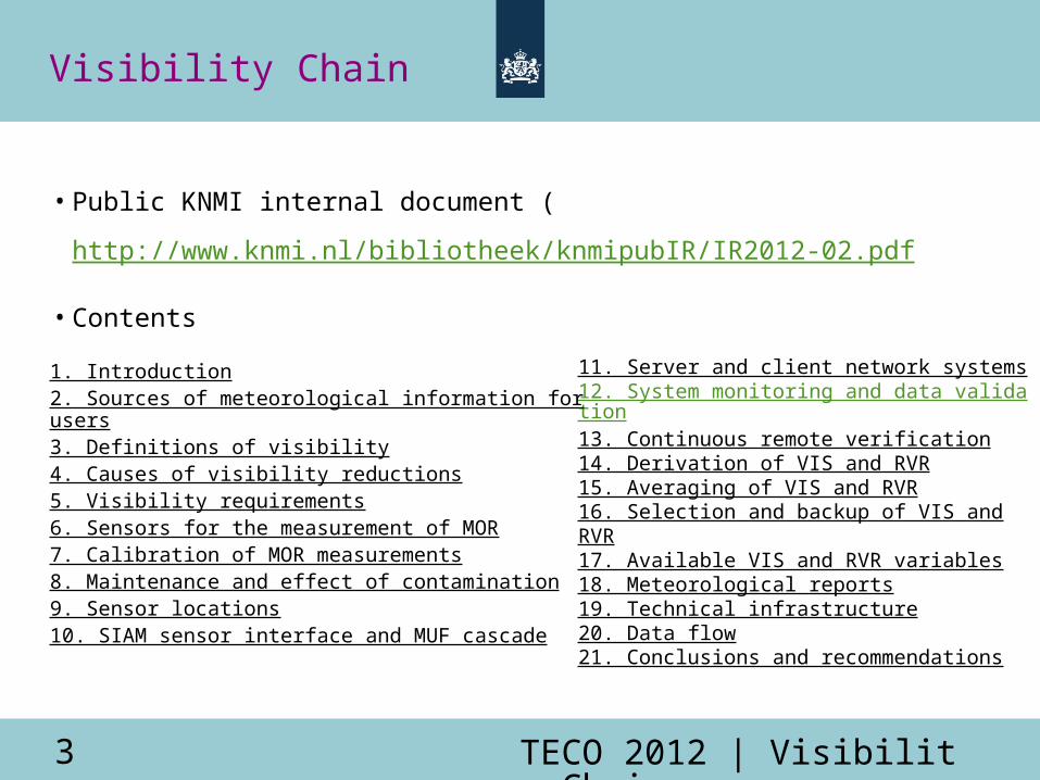
• Public KNMI internal document (
http://www.knmi.nl/bibliotheek/knmipubIR/IR2012-02.pdf
• Contents
11. Server and client network systems12. System monitoring and data validation13. Continuous remote verification14. Derivation of VIS and RVR15. Averaging of VIS and RVR16. Selection and backup of VIS and RVR17. Available VIS and RVR variables18. Meteorological reports19. Technical infrastructure20. Data flow21. Conclusions and recommendations
1. Introduction2. Sources of meteorological information for users3. Definitions of visibility4. Causes of visibility reductions5. Visibility requirements6. Sensors for the measurement of MOR7. Calibration of MOR measurements8. Maintenance and effect of contamination9. Sensor locations10. SIAM sensor interface and MUF cascade
TECO 2012 | Visibility Chain4
Visibility requirements
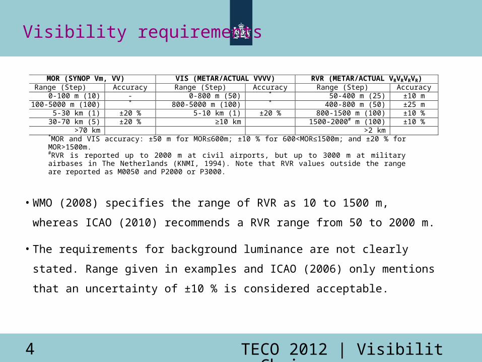
• WMO (2008) specifies the range of RVR as 10 to 1500 m, whereas
ICAO (2010) recommends a RVR range from 50 to 2000 m.
• The requirements for background luminance are not clearly stated.
Range given in examples and ICAO (2006) only mentions that an
uncertainty of ±10 % is considered acceptable.
MOR (SYNOP Vm, VV) VIS (METAR/ACTUAL VVVV) RVR (METAR/ACTUAL VRVRVRVR) Range (Step) Accuracy Range (Step) Accuracy Range (Step) Accuracy
0-100 m (10) - 0-800 m (50) * 50-400 m (25) ±10 m 100-5000 m (100) * 800-5000 m (100) * 400-800 m (50) ±25 m
5-30 km (1) ±20 % 5-10 km (1) ±20 % 800-1500 m (100) ±10 % 30-70 km (5) ±20 % ≥10 km 1500-2000# m (100) ±10 %
>70 km >2 km *MOR and VIS accuracy: ±50 m for MOR≤600m; ±10 % for 600<MOR≤1500m; and ±20 % for MOR>1500m. #RVR is reported up to 2000 m at civil airports, but up to 3000 m at military airbases in The Netherlands (KNMI, 1994). Note that RVR values outside the range are reported as M0050 and P2000 or P3000.
TECO 2012 | Visibility Chain5
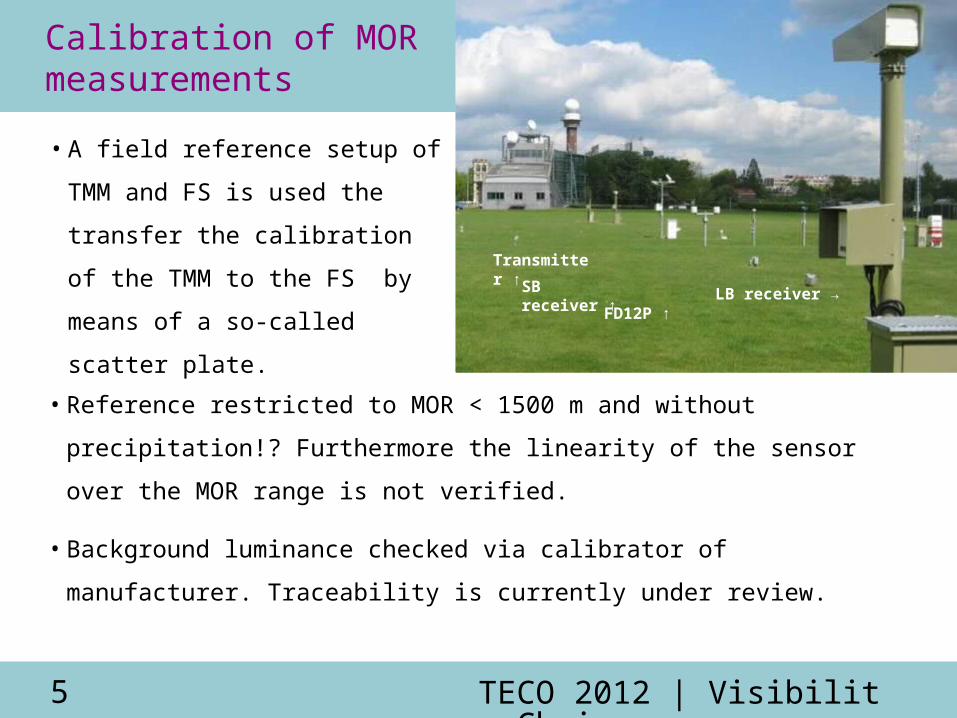
Calibration of MORmeasurements
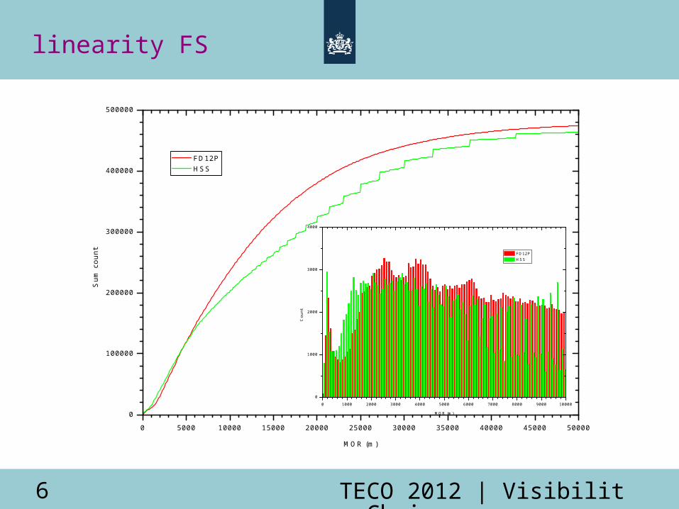
• Reference restricted to MOR < 1500 m and without precipitation!?
Furthermore the linearity of the sensor over the MOR range is not
verified.
• Background luminance checked via calibrator of manufacturer.
Traceability is currently under review.
Transmitter ↑
SB receiver ↑
FD12P ↑LB receiver →
• A field reference setup of TMM
and FS is used the transfer the
calibration of the TMM to the
FS by means of a so-called
scatter plate.
TECO 2012 | Visibility Chain6
0 5000 10000 15000 20000 25000 30000 35000 40000 45000 50000
0
100000
200000
300000
400000
500000
S
um c
ount
MOR (m)
FD12P HSS
linearity FS
0 1000 2000 3000 4000 5000 6000 7000 8000 9000 10000
0
1000
2000
3000
4000
Cou
nt
MOR (m)
FD12P HSS
TECO 2012 | Visibility Chain7
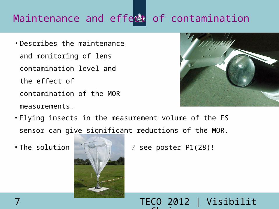
Maintenance and effect of contamination
• Flying insects in the measurement volume of the FS sensor can
give significant reductions of the MOR.
• The solution ... ? see poster P1(28)!
• Describes the maintenance
and monitoring of lens
contamination level and the
effect of contamination of the
MOR measurements.
TECO 2012 | Visibility Chain8
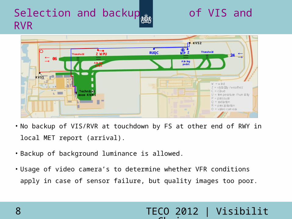
Selection and backup of VIS and RVR
• No backup of VIS/RVR at touchdown by FS at other end of RWY in local MET
report (arrival).
• Backup of background luminance is allowed.
• Usage of video camera’s to determine whether VFR conditions apply in
case of sensor failure, but quality images too poor.
KVS1
Technical room KNMI
W = windZ = visibility / weatherC = cloudU = temperature / humidityP = pressureQ = radiationR = precipitationO = video camera
↓↑WP ZRUQCWPUZ
KVS2
24↓↑ 06
Threshold
Aiming point
Threshold
Aiming point
TECO 2012 | Visibility Chain9
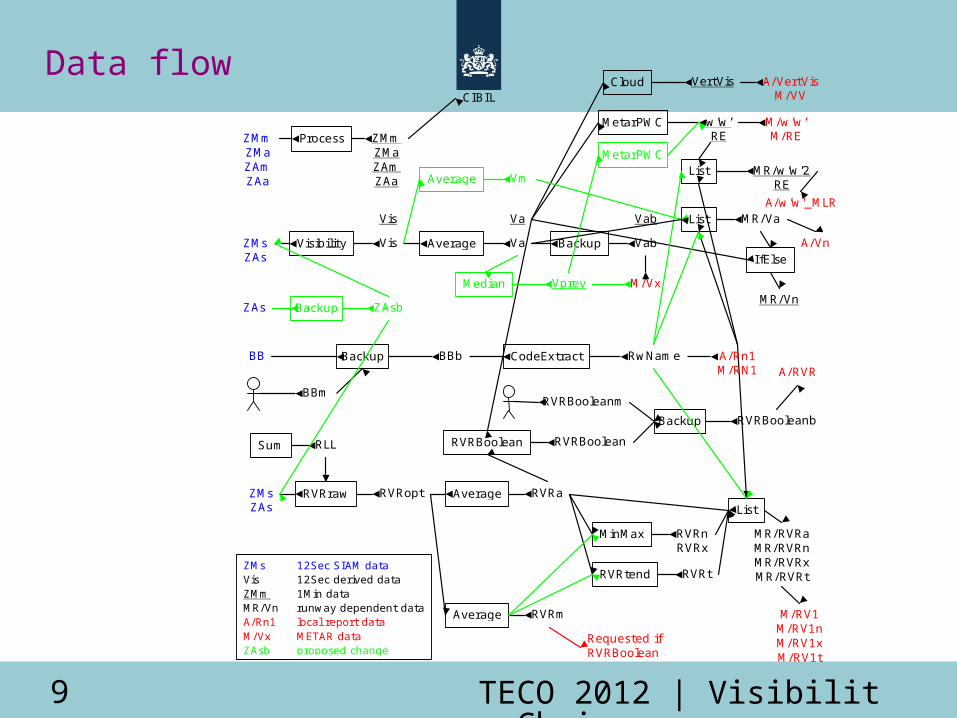
Data flow
ZAs Backup ZAsb
ZMm ZMa ZAm ZAa
Vis Va Vab
Visibility ZMs ZAs
Vis Average Va Backup Vab
List MR/Va
RVRraw ZMs ZAs
RVRopt
Average RVRm
Sum RLL
BB Backup BBb
BBm
RwName
RVRBooleanm
ZMm ZMa ZAm ZAa
Process
Average RVRa List
MR/RVRa MR/RVRn MR/RVRx MR/RVRt
MinMax
RVRtend
RVRn RVRx
RVRt
RVRBoolean RVRBoolean
Backup RVRBooleanb
w’w’ RE
MetarPWC
MR/w’w’2 RE
List
VertVis Cloud
I fElse
MR/Vn
A/RVR
A/VertVis M/VV
M/w’w’ M/RE
A/Vn
A/Rn1 M/RN1
M/Vx
M/RV1 M/RV1n M/RV1x M/RV1t
ZMs 12Sec SIAM data Vis 12Sec derived data ZMm 1Min data MR/Vn runway dependent data A/Rn1 local report data M/Vx METAR data ZAsb proposed change
CodeExtract
Requested if RVRBoolean
Median
CIBIL
A/w’w’_MLR
Vprev
MetarPWC
Vm Average
TECO 2012 | Visibility Chain10
Conclusions
• The review of the visibility chain was appreciated by internal and external users.
• During the review some errors in the chain could be pointed out. Some of these
were directly solved, but others require consensus between parties involved
and/or further investigations.
• The recommendations (37) are managed in a spreadsheet. Persons have been
assigned, but items have not yet been prioritised and sometimes their impact is
unclear. Meanwhile new items have been added to the list.
• The maintenance of the document is still under discussion. Inclusion in Dutch
handbook on observations versus coupling to documentation of the underlying
systems, regulations and agreements.
TECO 2012 | Visibility Chain11
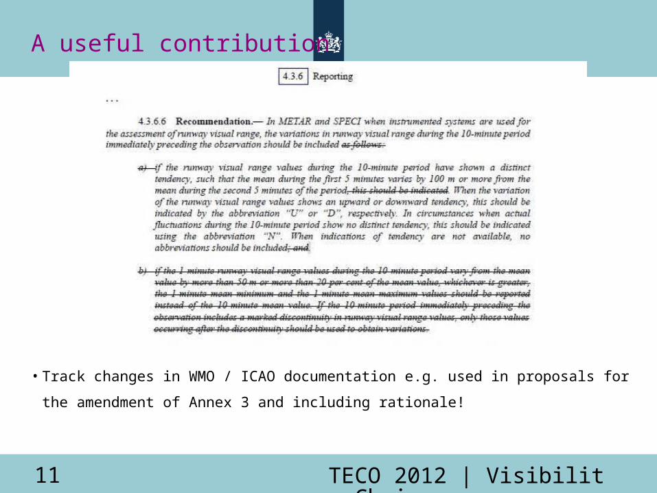
A useful contribution
• Track changes in WMO / ICAO documentation e.g. used in proposals for
the amendment of Annex 3 and including rationale!
Recommended


![HD VIDEO CAMERA RECORDER GebruikershandleidingTijdzone/zomertijd instellen 1. Druk op de MENU-toets. 2. Draai het SELECT/SET-wiel naar [SYSTEM SETUP/ ] en druk op het wiel. 3. Selecteer](https://img.pdfslide.us/doc/110x75/6031454b3aefb73b224c6c3d/hd-video-camera-recorder-gebruikershandleiding-tijdzonezomertijd-instellen-1-druk.jpg)