OPTIMIZING NEGATIVE STIFFNESS ELEMENTS IN NONLINEAR MECHANICAL VIBRATION ISOLATION AND DAMPING SYSTEMS.
Alex Mercado PI: Lorenzo Valdevit
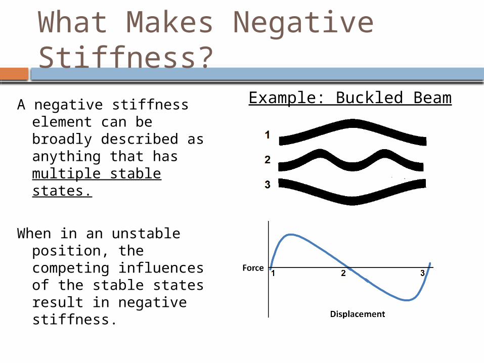
What Makes Negative Stiffness?
A negative stiffness element can be broadly described as anything that has multiple stable states.
When in an unstable position, the competing influences of the stable states result in negative stiffness.
Example: Buckled Beam

Advantages and Application Intent
Exceptional nonlinear shock and vibration isolation characteristics
Passive Materials
Both stiff and compliant behavior
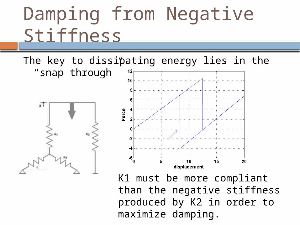
Damping from Negative StiffnessThe key to dissipating energy lies in the “snap
through”.
K1 must be more compliant than the negative stiffness produced by K2 in order to maximize damping.
Research Objective and Approach Optimize response of buckled beam
through variation in cross section: Maximize Fiso/Xiso Maximize Klin Remain at stress limit
Approach: Approximate with piecewise linear model Search for expandable exact analytical
solutions Computationally verify via FEA
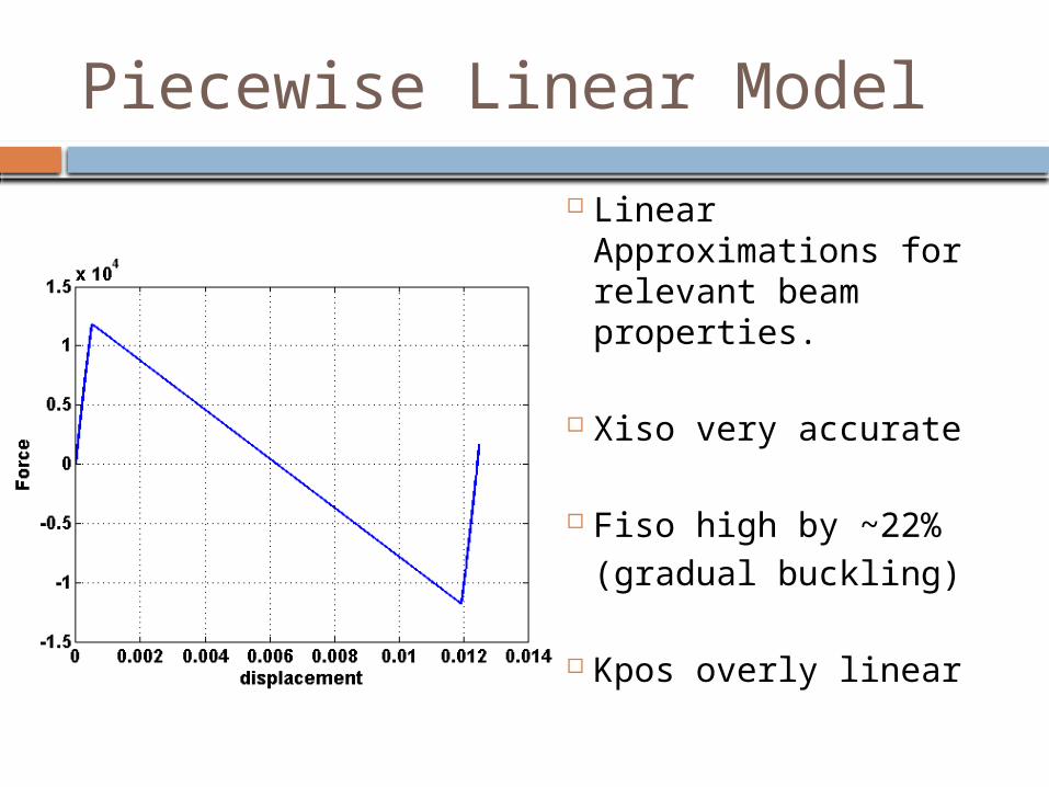
Piecewise Linear Model
Linear Approximations for relevant beam properties.
Xiso very accurate
Fiso high by ~22%(gradual buckling)
Kpos overly linear
0 2 4 6 8 10 120
50
100
150
200
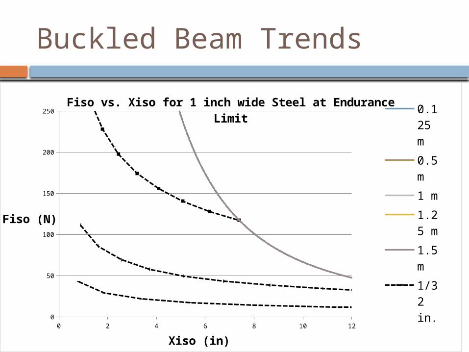
250Fiso vs. Xiso for 1 inch wide Steel at Endurance Limit 0.12
5 m0.5 m1 m1.25 m1.5 m1/32 in.1/16 in.1/8 in.
Xiso (in)
Fiso (N)
Buckled Beam Trends

A Few Relevant Papers:
Chen, Jen-San, and Shao-Yu Hung. "Exact Snapping Loads of a Buckled Beam Under a Midpoint Force." Applied Mathematical Modeling 36 (2012): 1776-82. Print.
Vangbo, Mattias. "An Analytical Analysis of a Compressed Bistable Buckled Beam." Sensors and Actuators 69 (1998): 212-16. Print.
Camescasse, B, A Fernandes, and J Pouget. "Bistable Buckled Beam: Elastica Modeling and Analysis of Static Actuation." International Journal of Solids and Structures 50 (2013): 2881-93. Print.

Computational Solutions
Note: You are seeing shell geometry rotated slightly about the x-axis

Postprocessing Stress Rate of Change
If and S are opposing signs then the beam is relaxing.
This beam is shaped for high initial stiffness:
xCompliance
Thin ends resemble pin joints, so this beam loses Fiso.
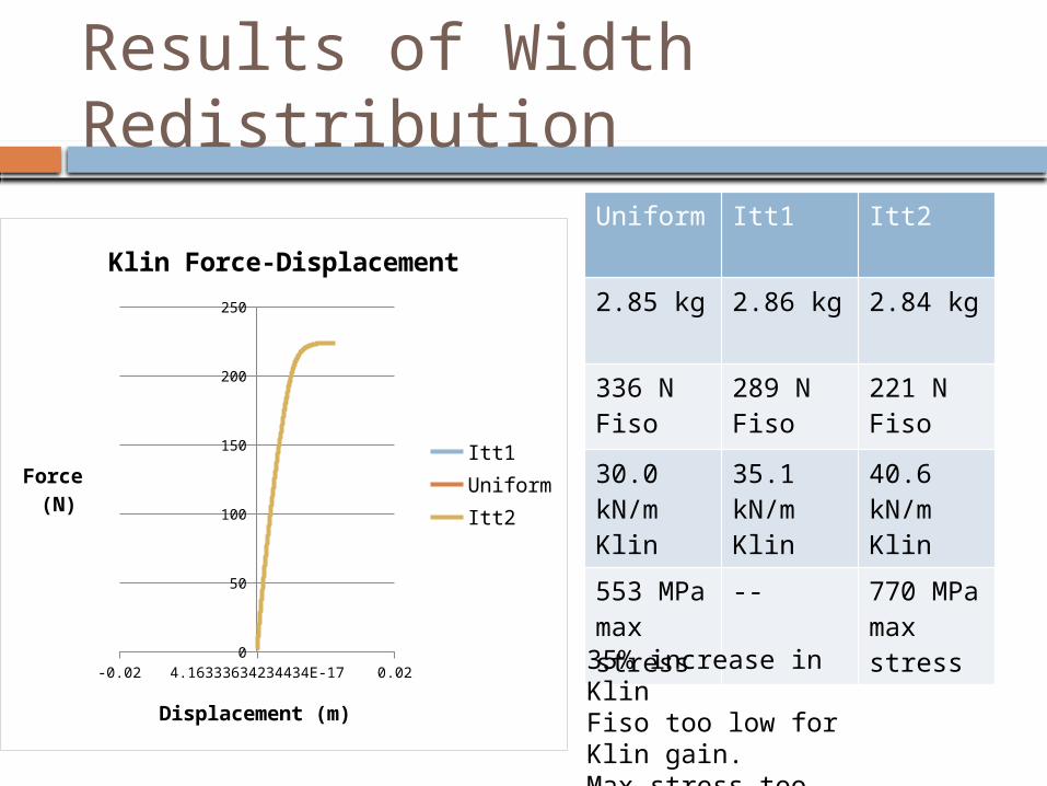
Results of Width Redistribution
-0.02 4.16333634234434E-17 0.020
50
100
150
200
250
Klin Force-Displacement
Itt1UniformItt2
Displacement (m)
Force (N)
Uniform Itt1 Itt2
2.85 kg 2.86 kg 2.84 kg
336 N Fiso
289 N Fiso
221 N Fiso
30.0 kN/m Klin
35.1 kN/m Klin
40.6 kN/m Klin
553 MPa max stress
-- 770 MPa max stress
35% increase in KlinFiso too low for Klin gain.Max stress too high.
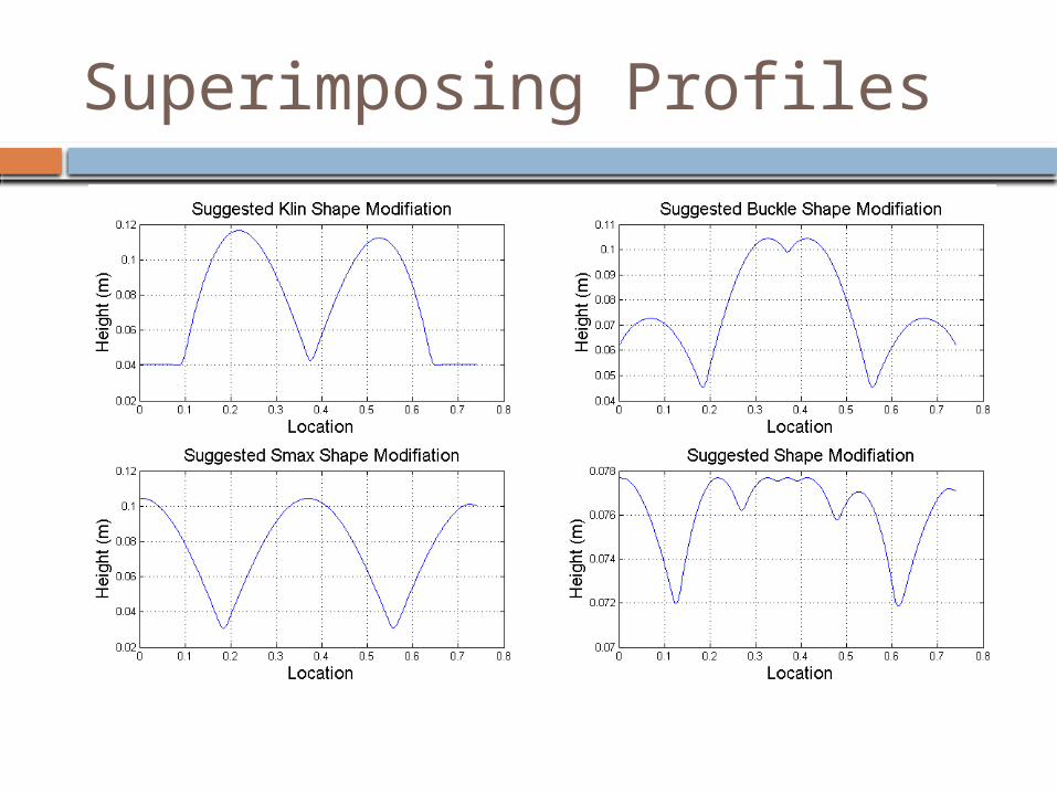
Superimposing Profiles

Results of Width Redistribution
-0.02 1.04083408558608E-17 0.02
-50
0
50
100
150
200
250
300
350
400
Klin Region Force-Displacement
UniformItt6
Displacement (m)
Force (N)
Uniform Itt6
2.85 kg 2.84 kg
336 N Fiso
350 N Fiso
30.0 kN/m Klin
30.7kN/m Klin
553 MPa max stress
**512 MPa max stress
** Maximum Stress Location Changed
Conclusions for Stress Derivative Method
1. Targeted changes in desired parameters can be made by varying width only.
2. Stress derivative method is inefficient for iterating.
3. Stress concentrations find their way to weaker regions, slower changes may work better.
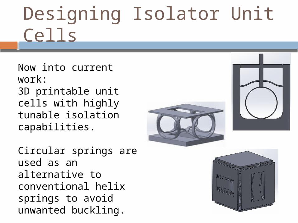
Designing Isolator Unit Cells
Now into current work:3D printable unit cells with highly tunable isolation capabilities.
Circular springs are used as an alternative to conventional helix springs to avoid unwanted buckling.
A printed sinusoidal arch possesses characteristics similar to the buckled beam.
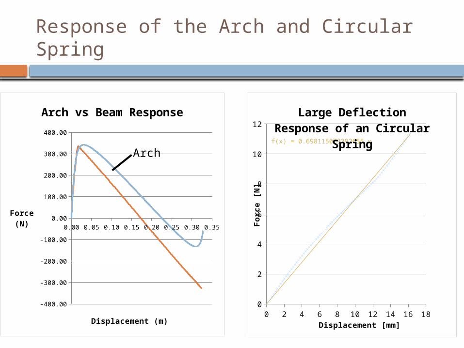
Response of the Arch and Circular Spring
0.00 0.05 0.10 0.15 0.20 0.25 0.30 0.35
-400.00
-300.00
-200.00
-100.00
0.00
100.00
200.00
300.00
400.00
Arch vs Beam Response
Displacement (m)
Force (N)
Arch
0 2 4 6 8 10 12 14 16 180
2
4
6
8
10
12
f(x) = 0.698115073292655 x
Large Deflection Re-sponse of an Circular
Spring
Displacement [mm]
Forc
e [
N]

Current Work
Writing sizing code for unit cells Braze stainless steel unit cell

QUESTIONS?
Recommended