Please read this manual before using this device.
This user manual is based on APP1.06.
TS80 Smart Soldering Iron
User Manual V1.1
Contents
1. Safety Statement
2. Overview
3. Power Adaptor Selection
4. Operation
5. Soldering Iron Tip
6. Trouble Shooting Guide
7.
8. Legal Statements
Service
P1
P3
P5
P6
P15
P17
P19
P21
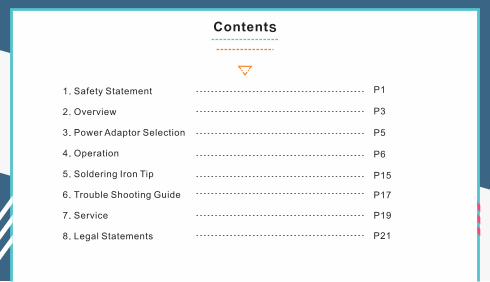
Safety Statement1
1
!
1.1 General Safety Use only certified power source/adaptors from your region.(please refer to 3.0 for specifications)
Do not operate in humid environment.
Do not operate in inflammable/explosive environment.
Keep the surface of the product clean and dry.
1.2 Warnings When using TS80,Turn the power off when not in use, or left unattended.When power is ON,tip temperatures will between 100℃~400℃ (212℉~752℉), please
be careful.Please don’t operate TS80 when it’s wet or operate it with wet hands, which will cause an electric shock.
1.3 Cautions The handle is constructed with precision, dropping shall be avoided.After continuous use at 350℃ up to 40 minutes, the handle surface temperature will
reach 50℃~60℃.
For the first time using, TS80 may generate a light smoke due to the heating of heating elements, which is a normal phenomenon.
2
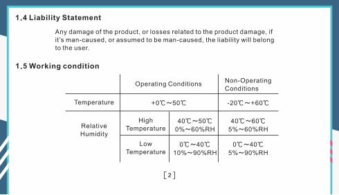
1.4 Liability Statement
Any damage of the product, or losses related to the product damage, if it’s man-caused, or assumed to be man-caused, the liability will belong to the user.
1.5 Working condition
Operating ConditionsNon-OperatingConditions
Temperature +0℃~50℃ -20℃~+60℃
40℃~50℃
0%~60%RH
40℃~60℃
5%~60%RH
0℃~40℃
10%~90%RH
0℃~40℃
5%~90%RH
HighTemperature
LowTemperature
RelativeHumidity
3
Overview2
①
②
③
④
⑤⑥⑦
⑧
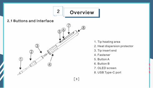
2.1 Buttons and Interface
1. Tip heating area
2. Heat dispersion protector
3. Tip insert end
4. Fastener
5. Button A
6. Button B
7. OLED screen
8. USB Type-C port
4
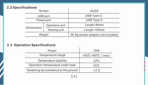
OLED
USB Type-C
USB Type-C
Length:96mm
Length:100mm
18W
100℃~400℃(max)
±3%
40℃
<2Ω
Screen
Dimensions
USB port
Power port
Heating unit
Operation unit
Weight
2.2 Specifications
36.5g (power adaptor not included)
2.3 Operation Specifications
Power
Temperature range
Temperature stability
Operation temperature under heat
Soldering tip resistance to the ground
5
Power Adaptor Selection3
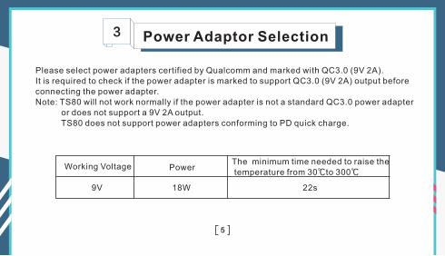
Please select power adapters certified by Qualcomm and marked with QC3.0 (9V 2A).It is required to check if the power adapter is marked to support QC3.0 (9V 2A) output before connecting the power adapter.Note: TS80 will not work normally if the power adapter is not a standard QC3.0 power adapter or does not support a 9V 2A output. TS80 does not support power adapters conforming to PD quick charge.
9V 18W 22s
Working Voltage PowerThe minimum time needed to raise the temperature from 30 to 300℃ ℃
6
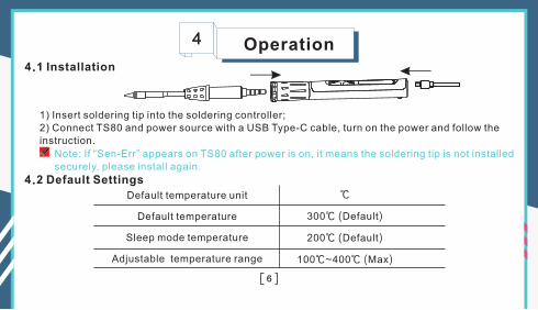
Operation4
4.2 Default Settings
4.1 Installation
1) Insert soldering tip into the soldering controller;2) Connect TS80 and power source with a USB Type-C cable, turn on the power and follow the instruction.
Default temperature unit
Default temperature
Sleep mode temperature
Adjustable temperature range
℃
300℃ (Default)
200℃ (Default)
100℃~400℃ (Max)
Note: If “Sen-Err” appears on TS80 after power is on, it means the soldering tip is not installed securely, please install again.
7
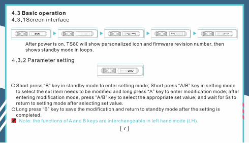
4.3 Basic operation4.3.1Screen interface
Ver1.02 Heating Setting
4.3.2 Parameter setting
Setting
After power is on, TS80 will show personalized icon and firmware revision number, then shows standby mode in loops.
Short press “B” key in standby mode to enter setting mode; Short press “A/B” key in setting mode to select the set item needs to be modified and long press “A” key to enter modification mode; after entering modification mode, press “A/B” key to select the appropriate set value; and wait for 5s to return to setting mode after selecting set value.Long press “B” key to save the modification and return to standby mode after the setting is completed.
Note: the functions of A and B keys are interchangeable in left hand mode (LH).
8
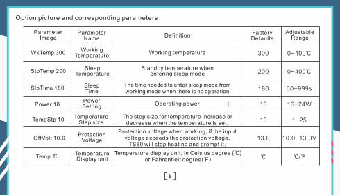
Option picture and corresponding parameters
Parameter Image
Power 18
WkTemp 300
StbTemp 200
SlpTime 180
TempStp 10
OffVolt 10.0
Temp ℃
Parameter Name
Working Temperature
Working temperature
①
300
200
180
18
10
13.0
℃
0-400℃
0-400℃
60-999s
16-24W
1-25
10.0-13.0V
℃/℉
DefinitionFactory Defaults
Adjustable Range
Temperature Display unit
Protection Voltage
Temperature Step size
SleepTime
Power Setting
SleepTemperature
Standby temperature when entering modesleep
The time needed to enter mode from working mode when there is no operation
sleep
Operating power
The step size for temperature increase or decrease when the temperature is set.
Protection voltage when working, if the input voltage exceeds the protection voltage,
TS80 will stop heating and prompt it.
Temperature display unit, in Celsius degree (℃) or Fahrenheit degree(℉)
9
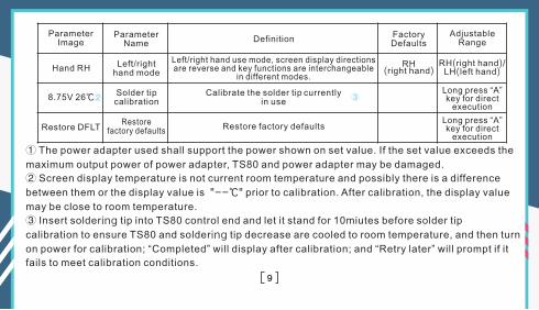
Parameter Image
Parameter Name
DefinitionFactory Defaults
Adjustable Range
Hand RH
8.75V 26℃
RH(right hand)
RH(right hand)/LH(left hand)
② ③
Restore DFLTRestore
factory defaults
Solder tip calibration
Left/right hand mode
Left/right hand use mode, screen display directions are reverse and key functions are interchangeable
in different modes.
Calibrate the solder tip currently in use
Restore factory defaultsLong press “A” key for direct
execution
① The power adapter used shall support the power shown on set value. If the set value exceeds the
maximum output power of power adapter, TS80 and power adapter may be damaged.
② Screen display temperature is not current room temperature and possibly there is a difference
between them or the display value is "--℃" prior to calibration. After calibration, the display value
may be close to room temperature.
③ Insert soldering tip into TS80 control end and let it stand for 10miutes before solder tip
calibration to ensure TS80 and soldering tip decrease are cooled to room temperature, and then turn
on power for calibration; “Completed” will display after calibration; and “Retry later” will prompt if it
fails to meet calibration conditions.
Long press “A” key for direct
execution
10
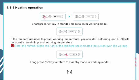
4.3.3 Heating operation
Heating 300℃8.88V
Short press “A” key in standby mode to enter working mode.
300℃8.88V
If the temperature rises to preset working temperature, you can start soldering, and TS80 will constantly remain in preset working temperature;
Note: the number at the top right of the temperature indicates the current working voltage.
Long press “B” key to return to standby mode in working mode;
11
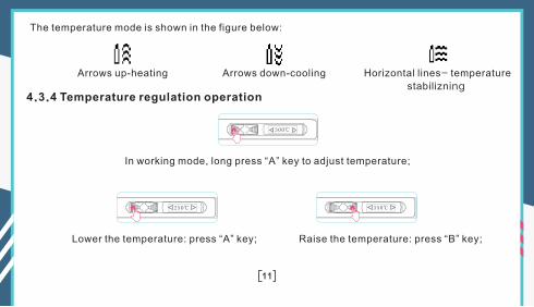
4.3.4 Temperature regulation operation
In working mode, long press “A” key to adjust temperature;
300℃
The temperature mode is shown in the figure below:
Arrows up-heating Arrows down-cooling Horizontal lines- temperature
stabilizning
Lower the temperature: press “A” key; Raise the temperature: press “B” key;
250℃ 350℃
12
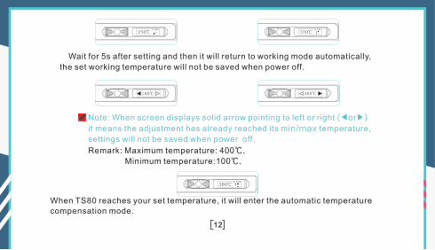
100℃ 400℃
Note: When screen displays solid arrow pointing to left or right (◀or▶)
it means the adjustment has already reached its min/max temperature,
settings will not be saved when power off.
Remark: Maximum temperature: 400℃.
Minimum temperature:100℃.
250℃8.88V
350℃8.88V
Wait for 5s after setting and then it will return to working mode automatically,
the set working temperature will not be saved when power off.
300℃8.88V
When TS80 reaches your set temperature, it will enter the automatic temperature compensation mode.
13
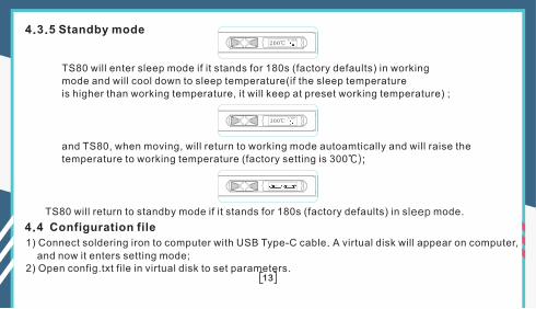
4.3.5 Standby mode
TS80 will enter sleep mode if it stands for 180s (factory defaults) in working mode and will cool down to temperature(if the temperature is higher than working temperature, it will keep at preset working temperature) ;
sleep sleep
and TS80, when moving, will return to working mode autoamtically and will raise the temperature to working temperature (factory setting is 300℃);
TS80 will return to standby mode if it stands for 180s (factory defaults) in mode. sleep
200℃8.88V
300℃8.88V
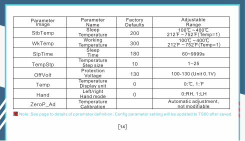
4.4 Configuration file
1) Connect soldering iron to computer with USB Type-C cable. A virtual disk will appear on computer,
and now it enters setting mode;2) Open config.txt file in virtual disk to set parameters.
14
StbTemp
WkTemp
SlpTime
TempStp
OffVolt
Temp
Hand
ZeroP_Ad
Note: See page to details of parameter definition; Config parameter setting will be updated to TS80 after saved.
Temperature Calibration
200
300
180
10
100℃~400℃212℉~752℉(Temp=1)
100℃~400℃212℉~752℉(Temp=1)
60~9999s
1-25
100-130 (Unit 0.1V)130
0
0 0:℃ 1:℉,
0:RH, 1:LH
Automatic adjustment, not modifiable
Parameter Name
Working Temperature
Left/right Hand mode
Temperature Display unit
Protection Voltage
Temperature Step size
SleepTime
SleepTemperature
Parameter Image
Factory Defaults
Adjustable Range
15
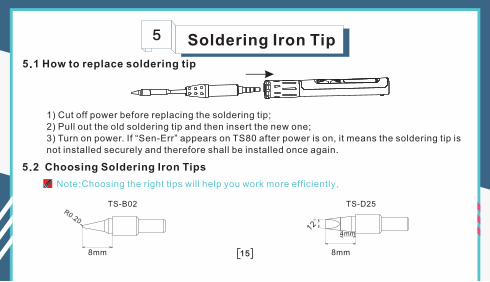
Soldering Iron Tip5
5.1 How to replace soldering tip
1) Cut off power before replacing the soldering tip;2) Pull out the old soldering tip and then insert the new one;3) Turn on power. If “Sen-Err” appears on TS80 after power is on, it means the soldering tip is not installed securely and therefore shall be installed once again.
12°
4mm
8mm8mm
R0.20
TS-D25TS-B02
5.2 Choosing Soldering Iron Tips
Note:Choosing the right tips will help you work more efficiently.
16
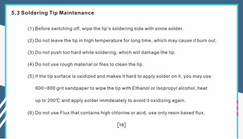
5.3 Soldering Tip Maintenance
(1) Before switching off, wipe the tip’s soldering side with some solder.
(2) Do not leave the tip in high temperature for long time, which may cause it burn out.
(3) Do not push too hard while soldering, which will damage the tip.
(4) Do not use rough material or files to clean the tip.
(5) If the tip surface is oxidized and makes it hard to apply solder on it, you may use
600~800 grit sandpaper to wipe the tip with Ethanol or Isopropyl alcohol, heat
up to 200℃ and apply solder immdeiately to avoid it oxidizing again.
(6) Do not use Flux that contains high chlorine or acid, use only resin based flux.
17
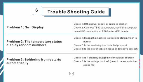
Trouble Shooting Guide6
Check 1: If the power supply or cable is brtoken
Check 2: Connect TS80 to computer, see if the computer
has a USB connection or TS80 enters DEU mode
Problem 2: The temperature status display random numbers
Check 1: Means the machine is checking status,which is
normal
Check 2: Is the soldering iron installed propely?
Check 3: Is the power cable in loose or defective contact?
Problem 3: Soldering iron restarts automatically
Check 1: Is it properly plugged into the power source?
Check 2: Is the voltage too low? (need to be set up in the
config file)
Problem 1: No Display
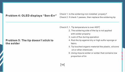
Problem 4: OLED displays “Sen-Err”Check 1: Is the soldering iron installed propely?
Check 2: If check 1 passes, then replace the soldering tip
Problem 5: The tip doesn’t stick to the solder
Check if: 1. Tip temperature is over 400℃
2. The soldering side of the tip is not applied
with solder properly
3. Lack of flux during operation
4. Rub the tip against dry or high sulfur sponge or
fabric
5. Tip touched organic material like plastic, silicone
oil or other chemicals
6. Using impure solder or solder that contains low
proportion of tin
18
19
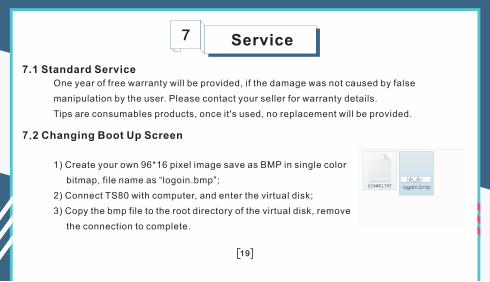
Service7
7.2 Changing Boot Up Screen
7.1 Standard ServiceOne year of free warranty will be provided, if the damage was not caused by false
manipulation by the user. Please contact your seller for warranty details.
Tips are consumables products, once it's used, no replacement will be provided.
1) Create your own 96*16 pixel image save as BMP in single color
bitmap, file name as “logoin.bmp”;
2) Connect TS80 with computer, and enter the virtual disk;
3) Copy the bmp file to the root directory of the virtual disk, remove
the connection to complete.
20
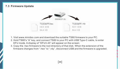
7.3 Firmware Update
1. Visit www.minidso.com and download the suitable TS80 firmware to your PC.2. Hold TS80's “A” key, and connect TS80 to your PC with USB Type-C cable, to enter DFU mode. A display of “DFU3.45” will appear on the screen;3. Copy the .hex firmware to the root directory of that disk. When the extension of the firmware changes from “.hex” to “.rdy”, disconnect USB and the firmware is upgraded.
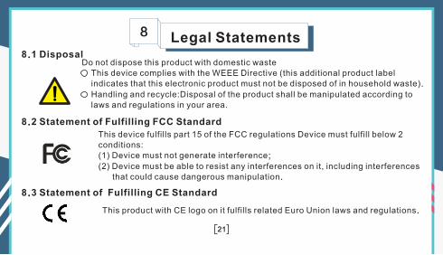
Legal Statements 8
Do not dispose this product with domestic waste This device complies with the WEEE Directive (this additional product label indicates that this electronic product must not be disposed of in household waste).
Handling and recycle:Disposal of the product shall be manipulated according to laws and regulations in your area.
21
8.1 Disposal
8.2 Statement of Fulfilling FCC Standard
8.3 Statement of Fulfilling CE Standard
This device fulfills part 15 of the FCC regulations Device must fulfill below 2conditions:(1) Device must not generate interference;
(2) Device must be able to resist any interferences on it, including interferences that could cause dangerous manipulation.
This product with CE logo on it fulfills related Euro Union laws and regulations.
Recommended