Embed Size (px)
Citation preview

Palmer Wahl • 234 Old Weaverville Road • Asheville, North Carolina • 28804-1260 Phone (800) 421-2853 • (828) 658-3131 • Fax (828) 658-0728 • Email: [email protected]
www.palmerwahl.com
ST2200 Soldering Iron Tester
User Manual
W-2176 Rev D 04/23/15
ST2200 Soldering Iron Tester User Manual
Page 2 of 34
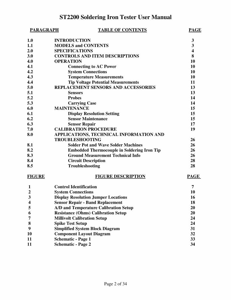
PARAGRAPH TABLE OF CONTENTS PAGE
1.0 INTRODUCTION 3
1.1 MODELS and CONTENTS 3
2.0 SPECIFICATIONS 4
3.0 CONTROLS AND ITEM DESCRIPTIONS 8
4.0 OPERATION 10
4.1 Connecting to AC Power 10
4.2 System Connections 10
4.3 Temperature Measurements 10
4.4 Tip Voltage Potential Measurements 11
5.0 REPLACEMENT SENSORS AND ACCESSORIES 13
5.1 Sensors 13
5.2 Probes 14
5.3 Carrying Case 14
6.0 MAINTENANCE 15
6.1 Display Resolution Setting 15
6.2 Sensor Maintenance 15
6.3 Sensor Repair 17
7.0 CALIBRATION PROCEDURE 19
8.0 APPLICATIONS, TECHNICAL INFORMATION AND
TROUBLESHOOTING 26
8.1 Solder Pot and Wave Solder Machines 26
8.2 Embedded Thermocouple in Soldering Iron Tip 26
8.3 Ground Measurement Technical Info 26
8.4 Circuit Description 28
8.5 Troubleshooting 28
FIGURE FIGURE DESCRIPTION PAGE
1 Control Identification 7
2 System Connections 10
3 Display Resolution Jumper Locations 16
4 Sensor Repair - Band Replacement 18
5 A/D and Temperature Calibration Setup 20
6 Resistance (Ohms) Calibration Setup 20
7 Millivolt Calibration Setup 24
8 Spike Test Setup 24
9 Simplified System Block Diagram 31
10 Component Layout Diagram 32
11 Schematic - Page 1 33
11 Schematic - Page 2 34
ST2200 Soldering Iron Tester User Manual
Page 3 of 34
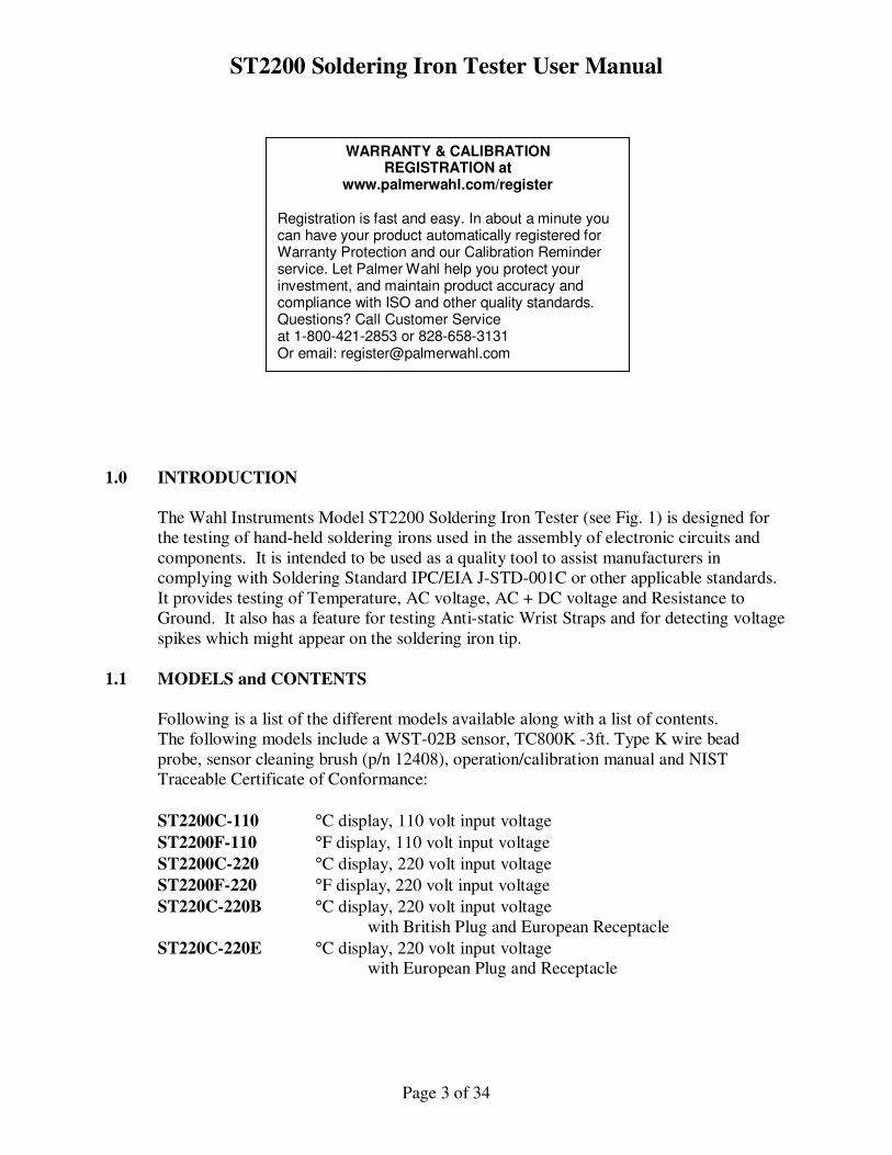
1.0 INTRODUCTION
The Wahl Instruments Model ST2200 Soldering Iron Tester (see Fig. 1) is designed for
the testing of hand-held soldering irons used in the assembly of electronic circuits and
components. It is intended to be used as a quality tool to assist manufacturers in
complying with Soldering Standard IPC/EIA J-STD-001C or other applicable standards.
It provides testing of Temperature, AC voltage, AC + DC voltage and Resistance to
Ground. It also has a feature for testing Anti-static Wrist Straps and for detecting voltage
spikes which might appear on the soldering iron tip.
1.1 MODELS and CONTENTS
Following is a list of the different models available along with a list of contents.
The following models include a WST-02B sensor, TC800K -3ft. Type K wire bead
probe, sensor cleaning brush (p/n 12408), operation/calibration manual and NIST
Traceable Certificate of Conformance:
ST2200C-110 °C display, 110 volt input voltage
ST2200F-110 °F display, 110 volt input voltage
ST2200C-220 °C display, 220 volt input voltage
ST2200F-220 °F display, 220 volt input voltage
ST220C-220B °C display, 220 volt input voltage
with British Plug and European Receptacle
ST220C-220E °C display, 220 volt input voltage
with European Plug and Receptacle
WARRANTY & CALIBRATION REGISTRATION at
www.palmerwahl.com/register
Registration is fast and easy. In about a minute you can have your product automatically registered for Warranty Protection and our Calibration Reminder service. Let Palmer Wahl help you protect your investment, and maintain product accuracy and compliance with ISO and other quality standards. Questions? Call Customer Service at 1-800-421-2853 or 828-658-3131 Or email: [email protected]
ST2200 Soldering Iron Tester User Manual
Page 4 of 34
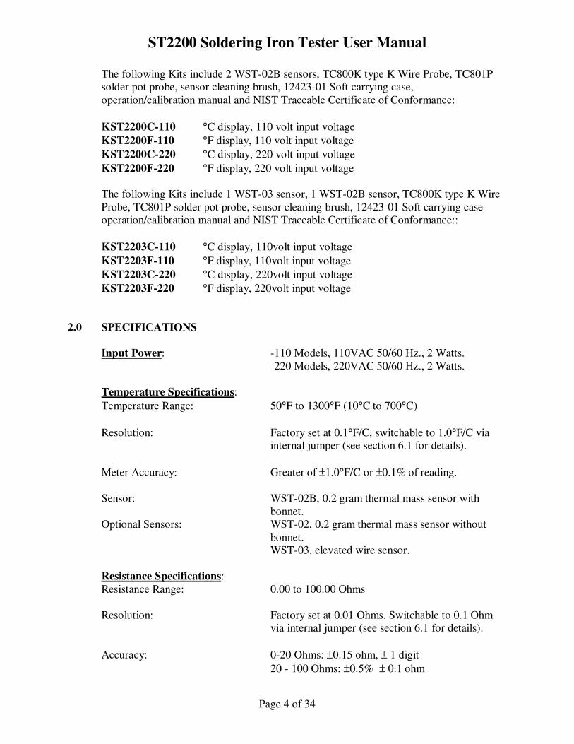
The following Kits include 2 WST-02B sensors, TC800K type K Wire Probe, TC801P
solder pot probe, sensor cleaning brush, 12423-01 Soft carrying case,
operation/calibration manual and NIST Traceable Certificate of Conformance:
KST2200C-110 °C display, 110 volt input voltage
KST2200F-110 °F display, 110 volt input voltage
KST2200C-220 °C display, 220 volt input voltage
KST2200F-220 °F display, 220 volt input voltage
The following Kits include 1 WST-03 sensor, 1 WST-02B sensor, TC800K type K Wire
Probe, TC801P solder pot probe, sensor cleaning brush, 12423-01 Soft carrying case
operation/calibration manual and NIST Traceable Certificate of Conformance::
KST2203C-110 °C display, 110volt input voltage
KST2203F-110 °F display, 110volt input voltage
KST2203C-220 °C display, 220volt input voltage
KST2203F-220 °F display, 220volt input voltage
2.0 SPECIFICATIONS
Input Power: -110 Models, 110VAC 50/60 Hz., 2 Watts.
-220 Models, 220VAC 50/60 Hz., 2 Watts.
Temperature Specifications:
Temperature Range: 50°F to 1300°F (10°C to 700°C)
Resolution: Factory set at 0.1°F/C, switchable to 1.0°F/C via
internal jumper (see section 6.1 for details).
Meter Accuracy: Greater of ±1.0°F/C or ±0.1% of reading.
Sensor: WST-02B, 0.2 gram thermal mass sensor with
bonnet.
Optional Sensors: WST-02, 0.2 gram thermal mass sensor without
bonnet.
WST-03, elevated wire sensor.
Resistance Specifications:
Resistance Range: 0.00 to 100.00 Ohms
Resolution: Factory set at 0.01 Ohms. Switchable to 0.1 Ohm
via internal jumper (see section 6.1 for details).
Accuracy: 0-20 Ohms: ±0.15 ohm, ± 1 digit
20 - 100 Ohms: ±0.5% ± 0.1 ohm
ST2200 Soldering Iron Tester User Manual
Page 5 of 34
Test Current: 10 mA DC
LED Warning Indicator: Factory set at 5.00 Ohms. Switchable to 2.00 Ohms
via internal jumper (see section 6.1 for details).
Millivolt Specifications:
Voltage Range: 0 - 30mV true RMS AC or AC+DC range.
Resolution: Factory set at 0.01 mV. Switchable to 0.1 mV via
internal jumper (see section 6.1 for details).
Accuracy: ±0.1mV ± 1 digit.
LED Warning Indicator: Indicates at 2.0mV threshold.
Digital Display: 4-1/2 digit LCD, 0.7" high characters.
Output Jack:
Type: .101" Subminiature phone jack
Temperature: 1.0 mV/degree, ±5°F.
Resistance: 100 mV/Ohm for the 0-30 Ohm range, ±0.15 Ohm.
Voltage: 100mV/mV for the 0-30mV range, ±0.15mV.
Protection: Short circuit and Over Voltage protected.
Auxiliary AC Outlet: Equipped with North American receptacle. Note:
220Volt models also equipped with North American
receptacle, marked as 220VAC.
Auxiliary T/C Connector: Mini Type K thermocouple female connector
provided for use with optional T/C probes.
User selectable by front panel switch.
Wrist Strap Tester: Activated in Resistance /Wrist Strap Test position.
Bi-color LED indicates Green when in acceptable
range of 500K to 10M ohms. Red when outside of
acceptable range.
Voltage Spike Detector: Activated in both Millivolt ranges. Indicates green
in no-fault condition and flashes red for approx.
ST2200 Soldering Iron Tester User Manual
Page 6 of 34
1 sec. when spike detected.
Spike Detect Threshold: >100mV amplitude, > 1 uS pulse width.
Ambient Environment: Operational: 45°F to 105°F (7.2°C to 40.5°C)
Storage: -4°F to 122°F (-20°C to 50°C)
Dimensions: 8.5"W x 10.5"D x 3.5"H
(21.59cm x 26.67cm x 8.89cm)
Weight: 3 lbs. (1.36 Kg)
Calibration Certificate: All units delivered with NIST Traceable Certificate
of Calibration.
ST2200 Soldering Iron Tester User Manual
Page 7 of 34
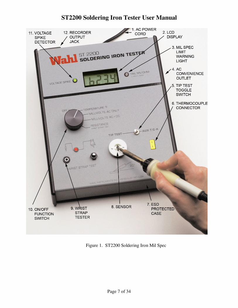
Figure 1. ST2200 Soldering Iron Mil Spec
ST2200 Soldering Iron Tester User Manual
Page 8 of 34
3.0 CONTROLS AND ITEM DESCRIPTIONS
Numbers in (parenthesis) Reference Figure 1.
3.1 (1) AC Power Cord
The ST2200F-110 and ST2200C-110 units come with a 5 foot long 3 wire North
American power cord. Models ST2200F-220 and ST2200C-220 come with a 5
foot long 3 wire European power cord. Cord storage is provided on integral cord
wraps on rear of the unit.
3.2 (2) LCD Display
Easy to read .7 inch high 4-1/2 digit display. Resolution is switchable via internal
jumper. See the Maintenance Section 6.1 for details on setting resolution.
3.3 (3) FAIL MV/OHM Indicator
This indicator serves as a Pass/Fail indicator for both MV and Resistance
measurements. It is a bi-color LED which displays Green when unit under test is
acceptable or flashes Red when the unit is unacceptable. See the Specifications
section 2.0 or the Operation section 4.0 for details on the threshold limits.
3.4 (4) AC Convenience Outlet
This outlet is provided as a power source for the Unit under Test. All units come
with a North American receptacle and have power available anytime the ST2200
is plugged in. NOTE: 220 volt models supply 220vac at this connector. It is
recommended to use this outlet as power source for your unit whenever possible,
to achieve optimal results.
3.5 (5) Input Selector Switch This switch selects between the ST2200 sensor and the Type K thermocouple
connector inputs. For soldering iron testing set Input Selector Switch to TIP
TEST position. Normal operation is the TIP TEST position. For Auxiliary type
K thermocouple probe input set Input Selector Switch to "AUX T/C - K" position.
Auxiliary probes may be used to test solder pots, wave solder baths, hot air guns
or ovens. See Accessories Section 5.0 for optional T/C probes for your specific
need.
3.6 (6) Auxiliary Thermocouple Connector
This input connector is provided to interface optional Type K thermocouple
probes to the ST2200 unit. With the input selector switch set to AUX T/C-K the
unit will use the signal input to this connector as the source for measurements.
3.7 (7) ESD Protected Case The ST2200 is designed for use in ESD protected areas. The case is grounded
and coated with chloride-free liquid anti-static protectant. The case has been
ST2200 Soldering Iron Tester User Manual
Page 9 of 34
tested for triboelectric effect during normal operation. It will neither generate a
charge nor support a static electricity discharge.
The internal circuitry of the ST2200 is protected against static discharge that may
be applied to the sensor during test of soldering irons or when the auxiliary
thermocouple connector is used.
3.8 (8) Sensor
ST2200 Soldering Iron Testers are shipped with Model WST-02B heavy duty
bead sensor. Sensors with bonnets are designed to aid in the positioning of the
iron tip. Sensors plug in for ease of maintenance or replacement. See
Accessories Section 5.0 for optional sensors.
3.9 (9) Wrist Strap Test
This area provides convenient go/no-go testing of wrist straps. It consists of a
jack for the wrist strap to plug in to, a grounded acorn nut for the operator to
touch and a bi-colored LED for test result indication.
3.10 (10) Power On-Off / Function Selector Switch Power is provided to the unit anytime the Function Selector Switch is in any
position other than OFF. In normal operation with the Function Selector Switch
in the TEMPERATURE position, the display will indicate ambient room
temperature. With the Function Selector Switch set to either MILLIVOLT
position or RESISTANCE position the display will indicate "1---" until the
soldering iron tip is placed in contact with the sensor.
3.11 (11) Voltage Spike Indicator This indicator serves as an indicator for the detection of voltage spikes detected
during MILLIVOLT testing. It is a bi-color LED which displays Green when no
spike is present and flashes Red when the spike is detected. See the
Specifications section 2.0 or the Operation section 4.0 for details on the spike
threshold limits.
3.12 (12) Recorder Output Jack
.101" Subminiature phone jack (Switchcraft p/n MDPC-2A-RA) for interfacing to
chart recorder or analog input card. See Specifications Section 2.0 for details.
ST2200 Soldering Iron Tester User Manual
Page 10 of 34
4.0 OPERATION
To make measurements on a soldering iron, connect the instruments as outlined below,
and preheat the iron to its operational temperature. For optimal results the Soldering Iron
under Test should be plugged into the AC Convenience Outlet on the right side of the
ST2200. For technical notes pertaining to measurements see Technical Information
Section 8.0.
4.1 Connecting to AC Power The ST2200 is a portable tester powered by 110 or 220VAC, depending on
specific model. Unwrap the AC power cord (1) from the integral Cord Wraps
located on the rear of the unit. Plug AC plug into appropriate AC receptacle. For
optimum operation, plug the soldering iron into the AC Convenience Outlet (4)
located on the right side of the ST2200. Note that for testing soldering irons that
will not be plugged into the ST2200's AC Convenience Outlet, the ST2200 should
be plugged into an AC receptacle with the identical ground wire as the irons to be
tested.
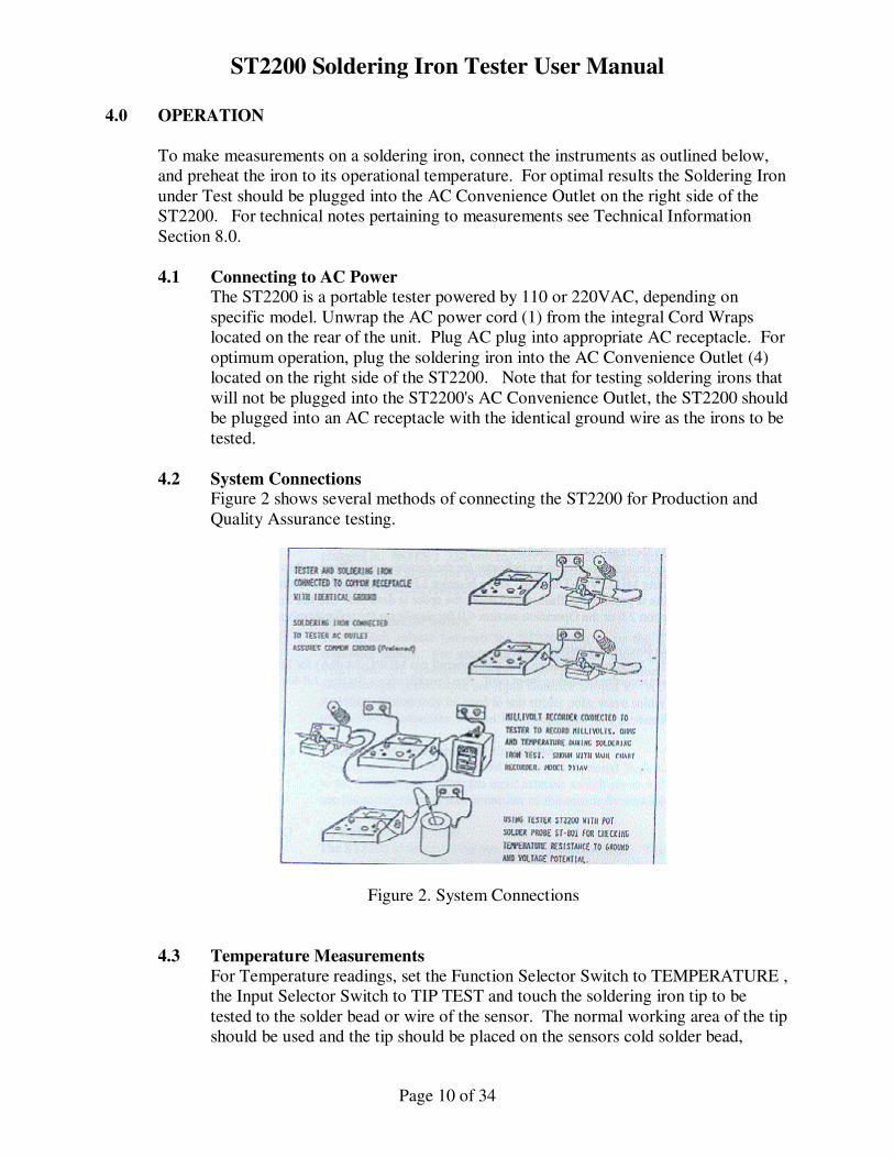
4.2 System Connections Figure 2 shows several methods of connecting the ST2200 for Production and
Quality Assurance testing.
Figure 2. System Connections
4.3 Temperature Measurements
For Temperature readings, set the Function Selector Switch to TEMPERATURE ,
the Input Selector Switch to TIP TEST and touch the soldering iron tip to be
tested to the solder bead or wire of the sensor. The normal working area of the tip
should be used and the tip should be placed on the sensors cold solder bead,
ST2200 Soldering Iron Tester User Manual
Page 11 of 34
allowing a few seconds for it to melt. This allows the sensing junction of the
sensor to be heated to the same temperature as the iron tip. Continue to hold the
same pressure as in soldering. The wire sensor WST-03, is best used by placing
the tip underneath the center of the wire and lifting with gentle pressure to assure
good contact. A small bead of solder should be placed on the iron tip at the area
to be measured. Watch the display and observe the temperature readings for:
a. Temperature rise as the tip heats and melts the solder bead on the sensor.
Equilibrium will be reached in about 5 - 10 seconds.
b. Temperature Stability. After reaching equilibrium expect only a few
degrees of temperature variations. Watch the display for the maximum
and minimum temperatures of the soldering iron over a period of 1 - 2
minutes. Watch for excessive temperature cycling due to a faulty
soldering iron controller.
c. Temperature recording can be made using the Recorder Output Jack.
The ST2200 displays the temperature of the working surface of the tip. It may not
agree with the indicated temperature of the soldering station or the setting of the
soldering iron control. Following are possible reasons:
a. The tip may be oxidized and may need to be cleaned and re-tinned.
b. May be due to the method the iron was last calibrated. Manufacturers may
use a special tip for calibration purposes which may be different from
your tip.
c. The ST2200 sensor may need to be cleaned and a new solder bead applied.
See section 6.2 for maintenance instructions. In some cases, after
prolonged use the sensor may need to be replaced. Replacement sensors
or sensor rebuilding kits are available from Wahl Instruments.
4.4 Tip Voltage Potential Measurements
The ST2200 has 2 methods of measuring the Voltage potential at the tip, AC only
or AC + DC.
4.4.1 Millivolts AC Only
When the ST2200 Function Selector Switch is in the MILLIVOLTS AC ONLY
position, the instrument will indicate the True RMS voltage of the unit under test,
when applied to the sensor. All measurements are made with respect to the Earth
Ground pin of the AC line plug.
The FAIL MV/OHM warning indicator (3) will flash red for any reading of 2.00
mV and above while the actual mV value is shown by the digital display. The
units range is 0.00 to 30.00 mV True RMS of AC voltage.
ST2200 Soldering Iron Tester User Manual
Page 12 of 34
If an oscilloscope is connected to the tip and the waveform viewed, with respect
to the soldering iron power ground, the basic frequency of the line power is seen
but the waveform may or may not be uniform. In most cases the waveform will
be distorted due to the effects of distributed capacitance throughout the soldering
iron heater and sensor circuitry. In any case, the True RMS feature of the ST2200
will measure the power content of the available signal and display it as an
engineering unit, RMS millivolts.
4.4.2 Millivolts AC + DC
When the ST2200 Function Selector Switch is in the MILLIVOLTS AC + DC
position the total True RMS value of all AC and all DC voltages at the tip are
measured and displayed.
The FAIL MV/OHM warning indicator (3) will flash red for any reading of 2.00
mV and above while the actual mV value is shown by the digital display. The
units range is 0.00 to 30.00 mV True RMS of AC + DC voltage.
4.4.3 Voltage Spike Detection The voltage spike detector is operational in mV mode of test only and when the
soldering iron tip is in contact with the ST2200 sensor. Detection of a potentially
damaging voltage spike is indicated by the Voltage Spike indicator (11) flashing
from GREEN to RED. Each voltage spike transient detected will flash the
indicator for approximately one second.
4.5 Resistance Measurement
The ST2200 measures resistance of the soldering iron probe tip to AC ground. To
measure, set the Function Selector Switch to the RESISTANCE setting and touch
the tip of the iron to the ST2200 sensor. If the resistance is less than 5.00 ohms
the FAIL MV/OHM indicator (3) will be green. When the resistance is equal to
or greater than 5.00 ohms the FAIL MV/OHM indicator (3) will flash red. The
actual value will be displayed in Ohms on the LCD display.
See Section 8.3 for more technical information on Resistance measurements and
Grounds.
4.6 Wrist Strap Test To test the wrist strap, connect the jack on the wrist strap cord to the Wrist Strap
Test Jack (9) on the ST2200. Set the Function Selector Switch to the
RESISTANCE - WRIST STRAP TEST position. Insure that the wrist strap is
worn on the wrist of the operator and is in intimate contact with the skin. Touch
the silver acorn nut located next to the Wrist Strap Test Jack with a finger. The
WRIST STAP INDICATOR will remain RED if the wrist strap is faulty or
change to GREEN if the wrist strap is acceptable.
ST2200 Soldering Iron Tester User Manual
Page 13 of 34
5.0 REPLACEMENT SENSORS AND ACCESSORIES
5.1 Sensors The ST2200 Soldering Iron Tester has several optional sensors available. The
unit comes standard with the WST-02B sensor. Following is a list of model
numbers and descriptions of the available sensors.
WST-02B, 0.2 gram thermal mass heavy duty sensor with bonnet.
WST-02, 0.2 gram thermal mass heavy duty sensor without bonnet.
WST-03, elevated wire sensor.
The replaceable temperature sensors WST-02, and WST-02B consist of a high
temperature Type K ribbon thermocouple, Stainless steel support strap, solder
bead, bonnet (WST-02B only) and glass filled teflon body.
The replaceable temperature sensor WST-03 consists of a welded thermocouple
wire sensor, support posts and glass filled teflon body. The WST-03 tip may be
used when the iron tip is not compatible with the WST-02 sensors. It is best used
by placing the tip underneath the center of the wire and lifting with gentle
pressure to assure good contact. A small bead of solder should be placed on the
iron tip at the area to be measured.
Type K thermocouple material is chosen for its high temperature stability,
accuracy and long life in the soldering temperature range of 500 - 900°F. It is a
good electrical conductor and therefore allows accurate measurements of tip
voltage potential and tip to ground resistance.
The solder bead is important because it simulates a solder joint, provides excellent
thermal transfer when melted by the iron and gives a good representation of
effective working temperature of the tip. It reforms on cooling. Add new solder
to the bead as necessary when the bead becomes dull. Best results occur when the
bead is new and shiny. For fast response use only a small amount of solder.
The bonnet acts as a position stop for the tip which gives repeatable temperature
readings with different operators, since it measures each tip in the identical
position. It also stabilizes the tip to prevent movement during measurement
which can cause temperature fluctuations. A 20° angle gives a good position of
the tip when placing it on the bead sensor.
The user may choose sensors to match the thermal capacity of the solder joint
when rating soldering irons and tips best suited to the work.
ST2200 Soldering Iron Tester User Manual
Page 14 of 34
5.1.1 Sensor Repair Kits Sensor repair kits are available for customers who wish to rebuild their own
sensors with factory supplied parts. Each kit contains a replacement sensor band,
screws, plugs and instructions for rebuilding your sensor. The following kits are
available.
WST-02KIT
WST-02BKIT
WST-03KIT
WST-02RT - Repair Tool Kit, includes holding fixture, removal tool and
screwdriver.
5.2 Probes
Many optional probes are available for use with the ST2200. We suggest the
following probes as possible solutions to your measurement task.
TC801P - Solder Pot probe for immersion measurements of solder pots or wave
solder baths. Will sense temperature to 1600°F, mV or resistance.
TC803 - Surface probe with low-mass. 0.032" diameter tip for measuring pc
board surfaces or component temperatures.
TC305 - Miniature Air probe for ambient air temperature or checking hot air
guns.
Please contact Wahl or visit our website for other available probes.
5.3 Carrying Case
12423-01 is a soft carrying case which will hold the ST2200, spare sensors, spare
probes and adapters. Provides excellent dust protection for your unit when not in
use.
ST2200 Soldering Iron Tester User Manual
Page 15 of 34
6.0 MAINTENANCE
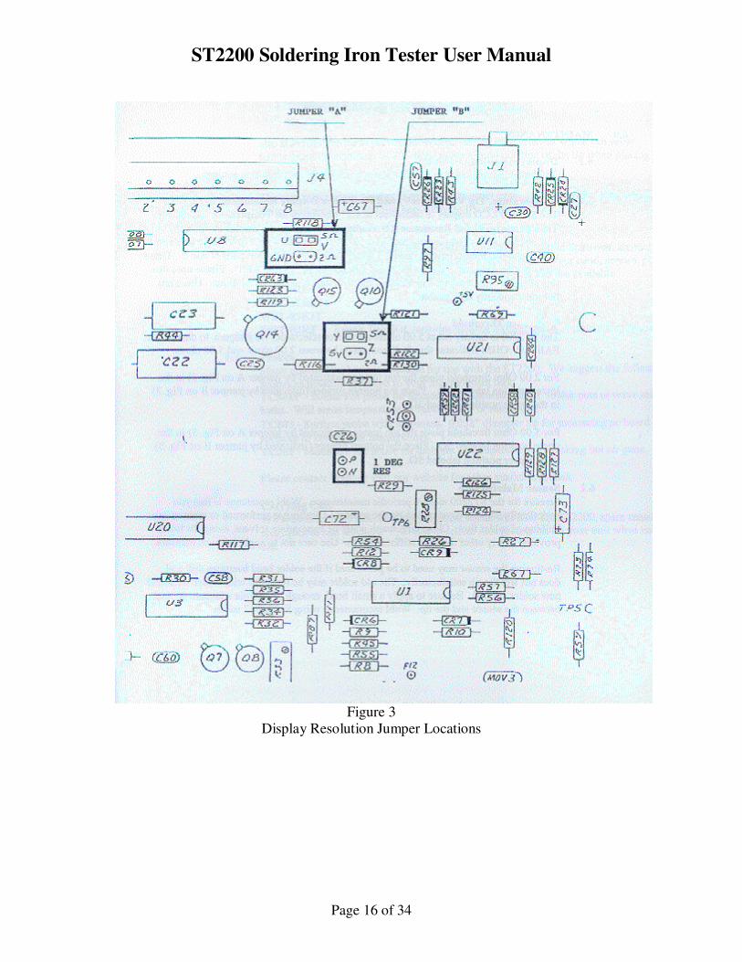
6.1 Display Resolution Setting Reference Figure 3 for the PC board jumper locations for resolution settings.
6.1.1 Temperature, Tip Voltage (mV) and Resistance Display Resolution
The ST2200 LCD display is factory set at 0.1° resolution for Temperature and .01
for Tip Voltage (mV) and Resistance (∧) readings. To change the resolution
from 0.1° to 1.0° resolution for Temperature and from .01 to .1 resolution for Tip
Voltage (mV) and Resistance (∧) measurements, solder a small jumper wire
between pads N and P. These pins are also designated on the PC board silk
screen as "1 DEG RES". Please note that this changes Temperature, Tip Voltage
and Resistance display resolutions. These are not independently changeable.
6.1.2 Resistance Threshold The ST2200 is factory set at 5.00 ohms but is user selectable, via jumpers, to
change the FAIL MV/OHM Indicator threshold resistance between 2.00 ohms and
5.00 ohms.
For 2.00 Ohm threshold place the top jumper (indicated by jumper A on Fig. 3) in
the lower position labeled 2∧ . Place the bottom jumper (indicated by jumper B
on Fig. 3) in the lower position labeled 2∧.
For 5.00 Ohm threshold place the top jumper (indicated by jumper A on Fig. 3) in
the upper position labeled 5∧. Place the bottom jumper (indicated by jumper B
on Fig. 3) in the upper position labeled 5∧.
6.2 Sensor Maintenance
Sensors for the ST2200 require periodic maintenance. Wahl recommends that
you periodically inspect, clean and re-tin the sensors. Cleaning is performed to
remove any buildup of solder flux. Clean with warm water or appropriate
solvent, using the brush provided or any other medium stiffness brush. Use care
not to apply to much pressure.
Re-tinning the sensor may need to be performed if the solder bead becomes dull
and does not wet the tip satisfactorily. The old solder may be removed with
solder wick and new solder applied. Be sure to apply a small bead, enough to
provide adequate contact between the sensor and the tip. Wahl recommends
using Sn63Pb37 solder
ST2200 Soldering Iron Tester User Manual
Page 16 of 34
Figure 3
Display Resolution Jumper Locations
ST2200 Soldering Iron Tester User Manual
Page 17 of 34
6.3 Sensor Repair
Sensors for the ST2200 are very sturdy and will give long life if not subjected to
excessive force during use. All sensors are repairable in the field. (with the
exception of model WST-01 (Discontinued.) See section 5.2 for repair and
tooling kits.
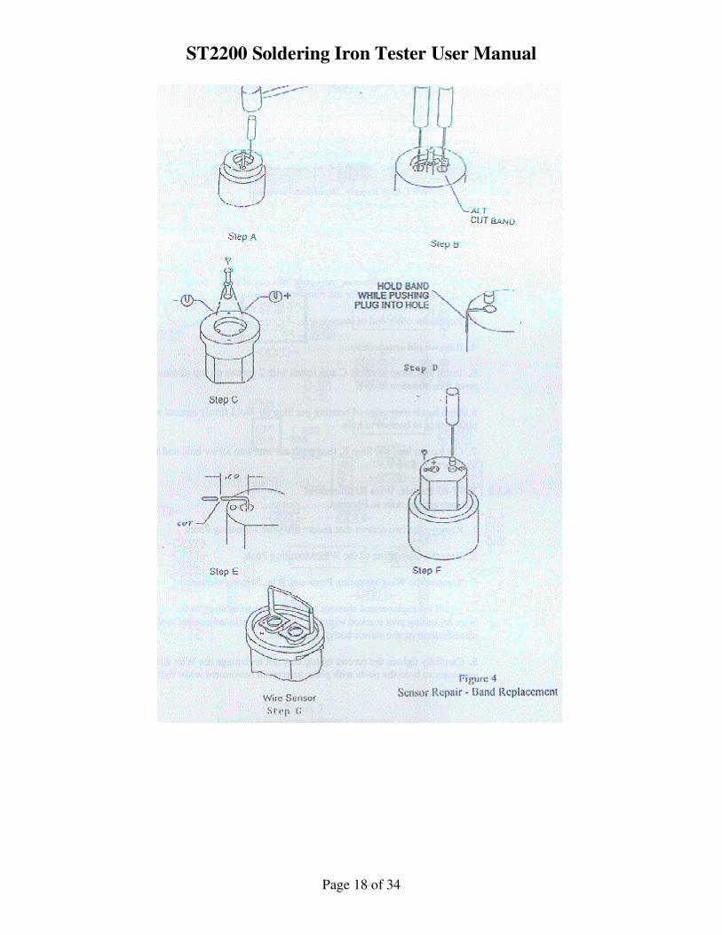
6.3.1 WST-02, WST-02B Repair, Band Replacement
All instruction reference Figure 4.
1. Remove two screws from bottom end of sensor, then turn over and remove two
screws from top of sensor.
2. Place sensor in holder per Steps A and B. Insert plug removal tool in sensor
strap and strike with small hammer until plug falls out of sensor body. It may
help to cut the bands to obtain clearance for the removal tool.
3. Repeat for other end of strap.
4. Remove old sensor strap.
5. Insert new strap per Step C and fasten with 2 screws on top of sensor. Arrow
point must face direction shown.
6. Bend bands over edge of housing per Step D. Hold firmly against side while
pushing plastic plug to bottom of hole.
7. Cut excess lead per Step E, then push cut lead into screw hole and install two
screws to secure per Step F.
6.3.2 WST-03 Repair, Wire Replacement All instructions refer to Figure 4.
1. Remove the two screws that secure the Wire Mounting Posts.
2. Note the orientation of the Wire Mounting Posts.
3. Remove the Wire Mounting Posts and Wire Sensing element.
4. Install the replacement element with the same orientation as the one removed.
The Wire Mounting post marked with a "+" is to be positioned nearest to the "+"
identification on the sensor body. See Step G.
5. Carefully tighten the screws taking care not to damage the Wire Element. It
may be necessary to hold the posts with pliers to prevent movement when
tightening screws.
ST2200 Soldering Iron Tester User Manual
Page 18 of 34
ST2200 Soldering Iron Tester User Manual
Page 19 of 34
7.0 CALIBRATION PROCEDURE
7.1 Purpose To describe instructions to calibrate Soldering Iron Tester Model ST2200 with
suffixes F or C and -110 or -220.
7.2 Scope This instruction applies to the above noted models and is to be used by qualified
electronic technicians.
7.3 Responsibility and Authority The Quality Manager is responsible for the implementation and effectiveness of
this procedure.
7.4 Definitions N.I.S.T.: National Institute of Standards and Technology
UUT : Unit Under Test
7.5 References N/A
7.6 Procedure
WARNING: AC Line Voltage is present in the cabinet and on the PC Board when unit is
plugged in to Power Source. Power switch DOES NOT have to be on for Voltage to be
present.
7.7 Equipment Needed
7.7.1 Thermocouple Simulator / D. C. Millivolt Source (referred to as "T/C Sim."
hereafter), such as AOIP Calys5 or Wahl C-65.
7.7.2 AC Milli-volt Generator
7.7.3 DVM with 1.0 milli-volt or less resolution and True RMS capability, such as
Keithley Instruments 177 or equivalent.
7.7.4 Pulse Generator
7.7.5 100∧ Decade Resistance Box with .01 ohm resolution.
7.7.6 Test leads for above, (1)banana to banana; (1) banana to alligator clip; T/C
Type K wire with alligator clips; Type K w/ mini male connector.
7.7.7 Fixed resistors for wrist strap test; approximate values of 450Kohm, 5M ohm,
11M ohm.
ST2200 Soldering Iron Tester User Manual
Page 20 of 34
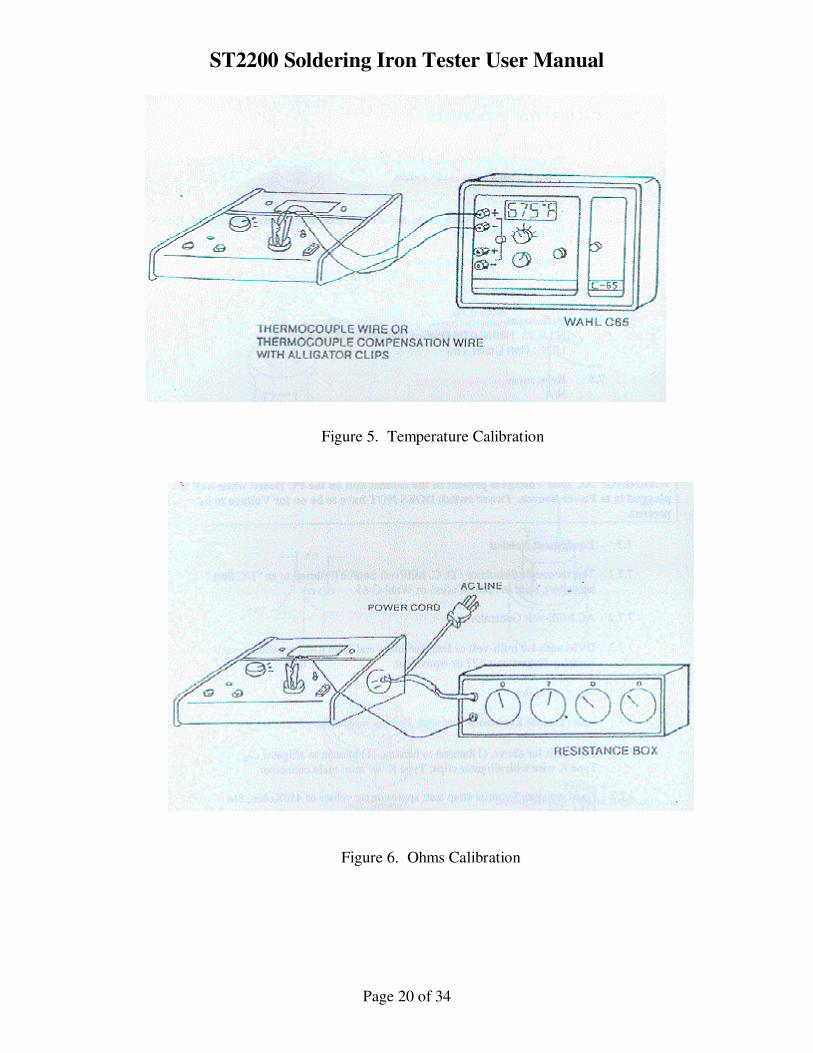
Figure 5. Temperature Calibration
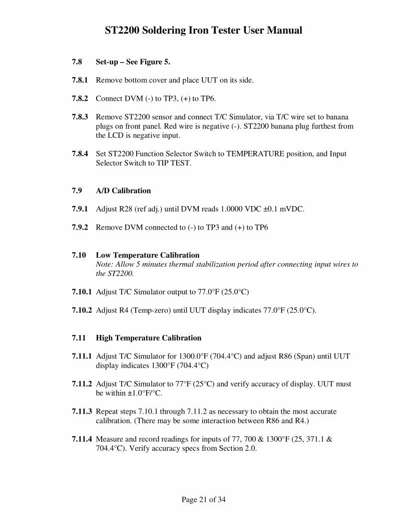
Figure 6. Ohms Calibration
ST2200 Soldering Iron Tester User Manual
Page 21 of 34
7.8 Set-up – See Figure 5.
7.8.1 Remove bottom cover and place UUT on its side.
7.8.2 Connect DVM (-) to TP3, (+) to TP6.
7.8.3 Remove ST2200 sensor and connect T/C Simulator, via T/C wire set to banana
plugs on front panel. Red wire is negative (-). ST2200 banana plug furthest from
the LCD is negative input.
7.8.4 Set ST2200 Function Selector Switch to TEMPERATURE position, and Input
Selector Switch to TIP TEST.
7.9 A/D Calibration
7.9.1 Adjust R28 (ref adj.) until DVM reads 1.0000 VDC ±0.1 mVDC.
7.9.2 Remove DVM connected to (-) to TP3 and (+) to TP6
7.10 Low Temperature Calibration Note: Allow 5 minutes thermal stabilization period after connecting input wires to
the ST2200.
7.10.1 Adjust T/C Simulator output to 77.0°F (25.0°C)
7.10.2 Adjust R4 (Temp-zero) until UUT display indicates 77.0°F (25.0°C).
7.11 High Temperature Calibration
7.11.1 Adjust T/C Simulator for 1300.0°F (704.4°C) and adjust R86 (Span) until UUT
display indicates 1300°F (704.4°C)
7.11.2 Adjust T/C Simulator to 77°F (25°C) and verify accuracy of display. UUT must
be within ±1.0°F/°C.
7.11.3 Repeat steps 7.10.1 through 7.11.2 as necessary to obtain the most accurate
calibration. (There may be some interaction between R86 and R4.)
7.11.4 Measure and record readings for inputs of 77, 700 & 1300°F (25, 371.1 &
704.4°C). Verify accuracy specs from Section 2.0.
ST2200 Soldering Iron Tester User Manual
Page 22 of 34
7.11.5 Set Input Selector Switch to AUX T/C-K, Connect the T/C simulator to the AUX
T/C-K input and allow 5 minutes thermal stabilization time.
7.11.6 Set T/C Simulator for 77, 700 & 1300°F (25, 371.1 & 704.4°C) and record data.
Verify within specs from section 2.0.
7.12 Ohms Calibration – See Figure 6.
7.12.1 Remove the T/C wires from UUT.
7.12.2 Connect test leads (22AWG or larger wire) to the decade box and set it for 0.00
ohms.
7.12.3 Measure Decade Box & leads with a precision Ohmmeter, such as the Agilent
3458A. The reading obtained must be added to all future decade box readings for
proper calibration. For example, if the leads measure 0.20 ohms, the proper
calibration when the decade box is set at 0.00 or 50.00 ohms will be 0.20 and
50.20 ohms respectively.
7.12.4 Connect the Decade Box as shown in Figure 6. For best results, solder a small
piece of wire to the solder bead of the tip sensor and attach the alligator clip from
the Decade Box to it.
7.12.5 Set Function Selector Switch to RESISTANCE and Input Selector Switch to TIP
TEST positions.
7.12.6 Set Decade Box to 0.00 ohms and adjust R33 for a reading equal to the value of
lead resistance found in step 7.12.3. For example, the ST2200 display should
display 0.20 ohms, for a measured lead resistance of 0.20 ohms.
7.12.7 Set Decade Box to 50.00 ohms and adjust R50 for a reading equal to the value of
lead resistance found in step 7.12.3 plus 50.00 ohms. For example, the ST2200
display should display 50.20 ohms, for a measured lead resistance of 0.20 ohms.
7.12.8 Repeat steps 7.12.6 and 7.12.7 for the best calibration.
7.12.9 Verify calibration by measuring and recording readings for inputs of 0.00, 2.00
and 50.00 ohm inputs.
ST2200 Soldering Iron Tester User Manual
Page 23 of 34
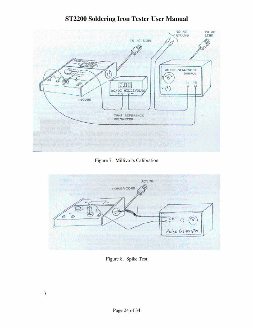
7.13 Millivolt Calibration AC ONLY- See Figure 7.
7.13.1 Connect the Millivolt source, True RMS Millivolt meter (AC reference voltmeter)
to ST2200 as shown in Figure 7. For best results, solder a small piece of wire to
the solder bead of the tip sensor and attach the alligator clip from the AC Millivolt
source to it.
7.13.2 Set the AC millivolt source to 50 or 60 Hz, depending on your local line
frequency. The source should be synchronized to the line frequency for best
results. Failure to do so may result in an unstable display for Millivolt readings.
7.13.3 Set Function Selector Switch to MILLIVOLTS AC ONLY and Input Selector
Switch to TIP TEST positions.
7.13.4 With the Millivolt Source power switch set to OFF, note the AC reference
voltmeter reading (call this V1) and adjust R19 for an ST2200 display reading of
0.02mV. NOTE: In the event that the unit is at 0.00mV and fluctuates negative
by as little as .01mV the FAIL MV/OHM indicator will flash Red, thus indicating
a false failure. To prevent this, an offset bias of .02mV is adjusted in during
calibration.
7.13.5 Turn the Millivolt Source power switch ON and adjust it’s output to 20.00mV
RMS plus V1 reading from step 7.13.4. The AC reference voltmeter should
indicate 20.00mV + V1.
7.13.6 Adjust R16 for a display of 20.00 mV RMS on the ST2200.
7.13.7 Turn the AC Millivolt Source power switch to OFF and touch up R19 as needed
for a 0.02 display reading on the ST2200. Repeat Steps 7.13.4 through 7.13.6 as
necessary for the best calibration.
ST2200 Soldering Iron Tester User Manual
Page 24 of 34
Figure 7. Millivolts Calibration
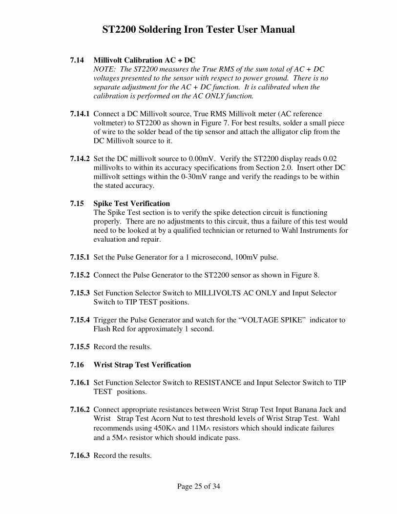
Figure 8. Spike Test
\
ST2200 Soldering Iron Tester User Manual
Page 25 of 34
7.14 Millivolt Calibration AC + DC
NOTE: The ST2200 measures the True RMS of the sum total of AC + DC
voltages presented to the sensor with respect to power ground. There is no
separate adjustment for the AC + DC function. It is calibrated when the
calibration is performed on the AC ONLY function.
7.14.1 Connect a DC Millivolt source, True RMS Millivolt meter (AC reference
voltmeter) to ST2200 as shown in Figure 7. For best results, solder a small piece
of wire to the solder bead of the tip sensor and attach the alligator clip from the
DC Millivolt source to it.
7.14.2 Set the DC millivolt source to 0.00mV. Verify the ST2200 display reads 0.02
millivolts to within its accuracy specifications from Section 2.0. Insert other DC
millivolt settings within the 0-30mV range and verify the readings to be within
the stated accuracy.
7.15 Spike Test Verification
The Spike Test section is to verify the spike detection circuit is functioning
properly. There are no adjustments to this circuit, thus a failure of this test would
need to be looked at by a qualified technician or returned to Wahl Instruments for
evaluation and repair.
7.15.1 Set the Pulse Generator for a 1 microsecond, 100mV pulse.
7.15.2 Connect the Pulse Generator to the ST2200 sensor as shown in Figure 8.
7.15.3 Set Function Selector Switch to MILLIVOLTS AC ONLY and Input Selector
Switch to TIP TEST positions.
7.15.4 Trigger the Pulse Generator and watch for the “VOLTAGE SPIKE” indicator to
Flash Red for approximately 1 second.
7.15.5 Record the results.
7.16 Wrist Strap Test Verification
7.16.1 Set Function Selector Switch to RESISTANCE and Input Selector Switch to TIP
TEST positions.
7.16.2 Connect appropriate resistances between Wrist Strap Test Input Banana Jack and
Wrist Strap Test Acorn Nut to test threshold levels of Wrist Strap Test. Wahl
recommends using 450K∧ and 11M∧ resistors which should indicate failures
and a 5M∧ resistor which should indicate pass.
7.16.3 Record the results.
ST2200 Soldering Iron Tester User Manual
Page 26 of 34
8.0 APPLICATIONS, TECHNICAL INFORMATION AND TROUBLESHOOTING
8.1 Solder Pot and Wave Solder Machines The ST2200 may also be used to measure solder pot and solder machine
temperature, voltage potential and ground resistance. Use the supplied wire probe
or the Optional Pot Solder Probe model TC801P.
1. Connect the probe to the Auxiliary input.
2. Switch the Input Selector Switch to the AUX T/C-K position.
3. Use the Function Selector Switch to select Temperature, Millivolts AC only, or
Resistance. Do not use the Millivolts AC + DC function as the thermocouple
wire induces a small DC voltage which gives an erroneous reading.
The Voltage Spike Detector is also operational when testing in the AUX T/C-K
position. This enables detection of transient voltage spikes in solder pots or wave
solder machines.
8.2 Embedded Thermocouple in Soldering Iron Tip
A soldering iron with Type K thermocouple embedded in the tip can be measured
using the AUX T/C-K input. The tip temperature can be measured either from the
AUX T/C-K input or the TIP TEST input.
Tip voltage potential measured from the embedded thermocouple will be accurate
on the AC only function. The AC+DC position will be in error due to
thermocouple effects. Tip Resistance measured from the embedded thermocouple
will be in error due to lead resistance.
8.3 Ground Measurement Technical Info
8.3.1 Soldering Iron Ground Circuit
For soldering of electronic components, 3-wire grounded soldering irons are
recommended. This is to provide a means of protecting electronic components
from damage due to voltage potential at the solder joint for any reason.
The ground path on many soldering irons contains mechanical joints between
replaceable tips, heater and the ground wire. These joints are subject to
loosening, contamination and aging, all of which affect the ground integrity.
Other designs have a direct ground connection to the tip which offers greater
promise of reliability in spite of aging.
Ground integrity is improved by frequent disassembly and cleaning of irons.
ST2200 Soldering Iron Tester User Manual
Page 27 of 34
8.3.2 Resistance to Ground Measurements All resistance measurements are made with respect to the ground reference of the
AC line cord. Therefore, the ST2200 line cord ground wire must be connected to
the ground reference as chosen by the user (either power ground or earth ground).
If a ground reference is chosen other than the ground available via the AC outlet
powering the soldering iron, then the ground reference of the ST2200 must be
connected to that ground to make tip resistance measurements.
The test current for resistance measurements is 10 milliamperes DC and the
ST2200 will display resistance with a resolution of 0.01 ohms. The operator
should be aware that it is possible for circulating ground currents in the AC power
distribution system to cause errors during ohms measurements. This will be
evidenced by a difference in displayed ohms when the soldering iron power cord
and ST2200 power cords are interchanged in their position of connection at the
AC power outlet. The reason for this is that a ground current is flowing in the
ground line and results in a voltage offset between the two adjacent outlets. In
one orientation this offset voltage adds to the ST2200 voltage generated during
ohms check and then subtracts if the orientation of the AC power cord
connections is reversed. Therefore, as little as 10 millivolts of either polarity will
cause a variance of the ST2200 digital display of ±1.0 ohms as the scale factor is
1.0 ohms per 10 millivolts of the voltage measured.
Should this phenomenon be seen, it would indicate that there is excessive ground
current flowing (caused by a faulty piece of equipment connected to the AC line)
or excessive resistance between AC outlets and should be resolved if highest
accuracy measurements are to be made.
Methods of avoiding the errors due to differences in ground potential are:
1. Use the AC convenience outlet provided on the right side of the instrument.
2. Use a multiple AC outlet adapter in which both the ST2200 and the soldering
iron under test are connected. This essentially connects the ground of the ST2200
and the soldering iron under test to a single point ground reference.
8.3.3 Ground Integrity
The Resistance (ohms) measurement will be most easily affected by an
unsatisfactory ground connection of either the ST2200 or the soldering iron under
test. Contact resistances of the AC power plug and receptacle combination can
have a wide variability depending on the surface area of contact, pressure of the
contact interface, and cleanliness. An open ground connection would indicate
itself as an "1---" on the display. When a Resistance measurement fails, the
connections to the AC line should be investigated for intermittent contact.
ST2200 Soldering Iron Tester User Manual
Page 28 of 34
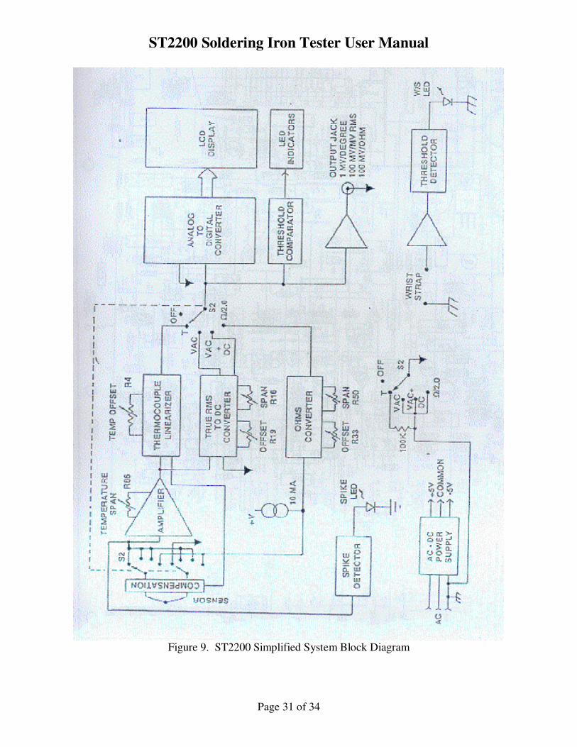
8.4 Circuit Description Figure 9 is a simplified block diagram of the ST2200. There are six distinct
measuring capabilities shown. During temperature measurement, the
thermocouple characteristics of the type K sensor are used and the microvolt
signals are amplified by the chopper stabilized amplifier, linearized, and
converted to a digital display of engineering units in degrees F or C, depending on
the model.
During the measurement of tip millivolts, the sensor is connected via the chopper
amplifier to a True RMS-to-DC converter which scales its output to 10 mV/mV of
True RMS input voltage. The tip millivolts are displayed in engineering units of
millivolts RMS.
The ohms circuitry consists of a precision 10mA DC current source and an ohms
converter circuit to provide the scaling and offsets necessary to display the tip
resistance to ground yet nulling out the resistance of the instrument and its power
cable. Ohms are displayed in engineering units of Ohms.
The analog to digital converter is a 16 bit dual slope converter which features auto
zero drift nulling capability and excellent long term stability.
The Display is a 0.7 inch, 4-1/2 digit, bright LCD display. In addition, peripheral
LED status indicators provide flashing go/no-go warnings at preset levels when
tip voltage or tip resistance exceed default levels.
The AC power inputs and sensor input are transient, static and surge protected for
the utmost in damage immunity. The output jack buffer is also protected against
shorts to ground and overvoltage inputs.
8.5 Troubleshooting When trouble occurs, it will usually center around three main areas.
1. Defective soldering irons which act erratically.
2. High ground path resistance for the ST2200 or the soldering iron under test.
3. A faulty ST2200.
8.5.1 Troubleshooting - Temperature Measurement Problems
Following are some suggestions for obtaining accurate readings or to solve
temperature measurement problems.
1. Make sure the soldering iron tip is clean and tinned properly. A small amount
of clean solder will insure a good thermal connection.
ST2200 Soldering Iron Tester User Manual
Page 29 of 34
2. Apply steady and firm (but not heavy) pressure to the sensor.
3. If display indicates "1---" with or without the soldering iron on it, it may
indicate an open ST2200 sensor. First, make sure the Input Selector Switch is in
the "TIP TEST" position. If it is install new sensor and try again. If the sensor is
working properly, the unit should display room ambient temperature when in
TEMPERATURE mode with no iron touching the sensor. If problem persists,
ST2200 may be faulty and should be serviced by qualified technician or returned
to Wahl for evaluation and repair.
8.5.2 Troubleshooting - Millivolt Measurement Problems If measurements are in doubt, connect a clip lead from the ST2200 sensor to
ground at the AC line. The display should indicate 0.00 to 0.10mV for a "zero"
input.
If it is out of this range, the ST2200 may need calibration or repair. Try
reconnecting the ST2200 AC cord at the AC line and try again. The contact
resistance of the ground connection at the AC line is not a major factor, but if it is
over 100 ohms, erratic readings may appear. Switch to the "RESISTANCE" and
measure the resistance of the soldering iron back to the AC line. If more than the
5 ohms or so is measured, there may be a problem with the ground in the
soldering iron or the AC line receptacle.
8.5.3 Troubleshooting - Resistance Measurement Problems
The contact resistance from the soldering iron power cord to the AC line and the
contact resistance from the ST2200 power cord to the AC line will cause most of
the indicated error in this measurement assuming the soldering iron itself is under
5.00 ohms.
Following are some suggestions for obtaining accurate readings or to solve
Resistance Measurement problems.
1. High or erratic readings - Remove the AC line cord and reconnect for both the
soldering iron and ST2200 and try again. If still high, connect the soldering iron
to the AC power receptacle on the ST2200 and measure again. If still high,
connect a clip lead from the ST2200 sensor to ground and verify that there is
resistance of no more than 0.10 ohms.
If the clip lead test is fine but the soldering iron test was high, it points to the
soldering iron as the problem.
2. Display always reads"1---". Replace the ST2200 sensor and try again with a
soldering iron or clip lead from ST2200 sensor to ground. If the display still reads
open, check the ground where the ST2200 line cord is plugged in. Sometimes the
AC receptacle ground clips break and a ground connection is not available even
though AC power is available to the ST2200.
ST2200 Soldering Iron Tester User Manual
Page 30 of 34
Move equipment to another AC outlet and repeat the above tests. If the ground
has been verified and the ST2200 sensor has been replaced but the over range
indication of "1---" still exists, return the ST2200 to the factory for evaluation and
repair.
8.5.4 Troubleshooting - Wrist Strap Test Problems If a wrist strap under test indicates a failure, following are possible causes.
1. Check that the wrist strap cable connector is connected properly to the
ST2200. See Figure 1, Item 9 for wrist strap connector location. Do not rely on
common ground of AC line for wrist strap testing.
2. Make sure the operator is not touching any other conductive material. Ensure
that the operator’s free hand is not in contact with any other object.
3. Make sure wrist strap is in contact with the skin. Do not wear the wrist strap
over clothing.
4. Wrist strap may be defective, replace wrist strap.
ST2200 Soldering Iron Tester User Manual
Page 31 of 34
Figure 9. ST2200 Simplified System Block Diagram
ST2200 Soldering Iron Tester User Manual
Page 32 of 34
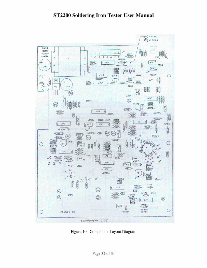
Figure 10. Component Layout Diagram
ST2200 Soldering Iron Tester User Manual
Page 33 of 34
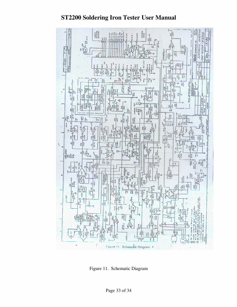
Figure 11. Schematic Diagram
ST2200 Soldering Iron Tester User Manual
Page 34 of 34
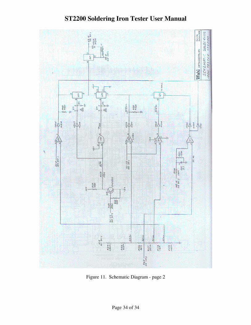
Figure 11. Schematic Diagram - page 2