Towbar Fitting Instructions To Suit MAZDA CX-9 TC CL4
Part Number QTMA660L Rating 2000/100 kg
PLACE THESE INSTRUCTIONS IN THE VEHICLE’S GLOVEBOX AFTER INSTALLATION IS COMPLETED
Cequent Customer Service Ph: 1800 812 017 Fax: 03 9898 3299
Email: [email protected] Post: PO Box 4050, Dandenong South VIC 3175
Rev: A Page 1 Issue Date: 24-01-2017
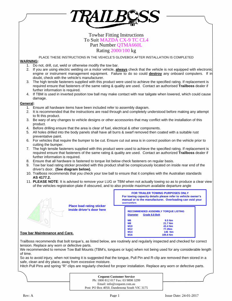
FOR TRAILER TOWING PURPOSES ONLY For towing capacity details please refer to vehicle owner’s manual or to the manufacturer. Overloading can void your warranties.
WARNING: 1. Do not, drill, cut, weld or otherwise modify the tow bar. 2. If you are using electric welding on a motor vehicle, always check that the vehicle is not equipped with electronic
engine or instrument management equipment. Failure to do so could destroy any onboard computers. If in doubt, check with the vehicle's manufacturer.
3. The high tensile fasteners supplied with this product were used to achieve the specified rating. If replacement is required ensure that fasteners of the same rating & quality are used. Contact an authorised Trailboss dealer if further information is required.
4. If TBM is used in inverted position tow ball may make contact with rear tailgate when lowered, which could cause damage.
General: 1. Ensure all hardware items have been included refer to assembly diagram. 2. It is recommended that the instructions are read through and completely understood before making any attempt
to fit this product. 3. Be wary of any changes to vehicle designs or other accessories that may conflict with the installation of this
product. 4. Before drilling ensure that the area is clear of fuel, electrical & other components. 5. All holes drilled into the body panels shall have all burrs & swarf removed then coated with a suitable rust
preventative paint. 6. For vehicles that require the bumper to be cut. Ensure cut out area is in correct position on the vehicle prior to
cutting the bumper. 7. The high tensile fasteners supplied with this product were used to achieve the specified rating. If replacement is
required ensure that fasteners of the same rating & quality are used. Contact an authorized Trailboss dealer if further information is required.
8. Ensure that all hardware is fastened to torque list below check fasteners on regular basis. 9. Tow bar load rating sticker provided with this product shall be conspicuously located on inside rear end of the
driver's door. (See diagram below). 10. Trailboss recommends that you check your tow ball to ensure that it complies with the Australian standards
AS 4177.2. 11. PLEASE NOTE: It is advised to remove your LUG or TBM when not actually towing so as to produce a clear view
of the vehicles registration plate if obscured, and to also provide maximum available departure angle
Tow bar Maintenance and Care. Trailboss recommends that bolt torque’s, as listed below, are routinely and regularly inspected and checked for correct tension. Replace any worn or defective parts. We recommended to remove Tow Ball Mounts (TBM’s, tongues or lugs) when not being used for any considerable length of time. So as to avoid injury, when not towing it is suggested that the tongue, Pull Pin and R-clip are removed then stored in a safe, clean and dry place, away from excessive moisture. Hitch Pull Pins and spring “R” clips are regularly checked for proper installation. Replace any worn or defective parts.
Place load rating sticker inside driver’s door here
RECOMMENDED ASSEMBLY TORQUE LISTING Diameter Grade 8.8 Bolt M6 9.5 Nm M8 21.7 Nm M10 43.4 Nm M12 77.3Nm M14 146 Nm M16 189.8 Nm
Towbar Fitting Instructions To Suit MAZDA CX-9 TC CL4
Part Number QTMA660L Rating 2000/100 kg
PLACE THESE INSTRUCTIONS IN THE VEHICLE’S GLOVEBOX AFTER INSTALLATION IS COMPLETED
Cequent Customer Service Ph: 1800 812 017 Fax: 03 9898 3299
Email: [email protected] Post: PO Box 4050, Dandenong South VIC 3175
Rev: A Page 2 Issue Date: 24-01-2017
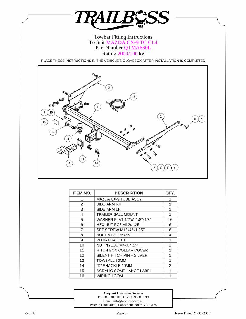
ITEM NO. DESCRIPTION QTY.
1 MAZDA CX-9 TUBE ASSY 1 2 SIDE ARM RH 1 3 SIDE ARM LH 1 4 TRAILER BALL MOUNT 1 5 WASHER FLAT 1/2”x1 1/8”x1/8” 16 6 HEX NUT PC8 M12x1.25 6 7 SET SCREW M12x45x1.25P 6 8 BOLT M12-1.25x35 4 9 PLUG BRACKET 1 10 NUT NYLOC M4-0.7 Z/P 2 11 HITCH BOX COLLAR COVER 1 12 SILENT HITCH PIN – SILVER 1 13 TOWBALL 50MM 1 14 “D” SHACKLE 10MM 2 15 ACRYLIC COMPLIANCE LABEL 1 16 WIRING LOOM 1
Towbar Fitting InstructionsTo Suit MAZDA CX-9 TC CL4
Part Number QTMA660LRating 2000/100 kg
PLACE THESE INSTRUCTIONS IN THE VEHICLE’S GLOVEBOX AFTER INSTALLATION IS COMPLETED
Cequent Customer Service Ph: 1800 812 017 Fax: 03 9898 3299
Email: [email protected] Post: PO Box 4050, Dandenong South VIC 3175
Rev: A Page 3 Issue Date: 24-01-2017
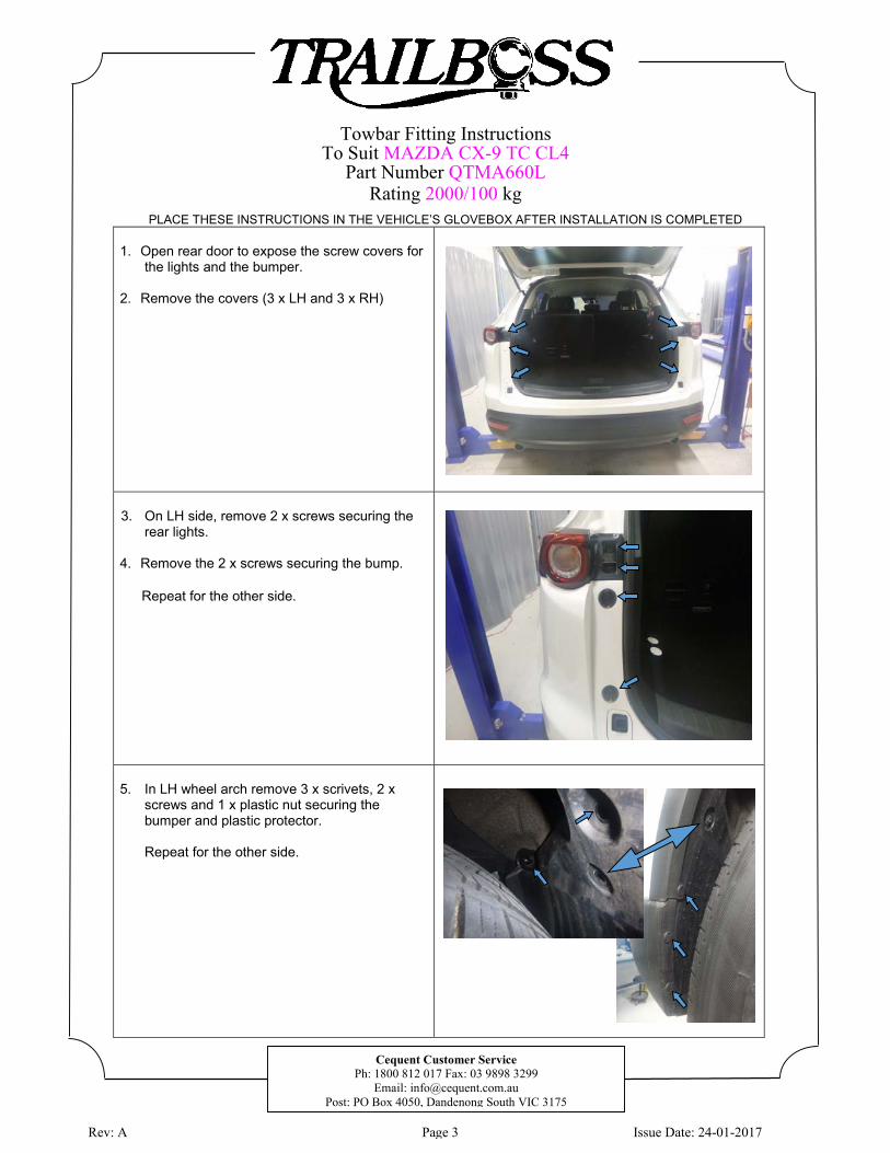
1. Open rear door to expose the screw covers for the lights and the bumper.
2. Remove the covers (3 x LH and 3 x RH)
3. On LH side, remove 2 x screws securing the rear lights.
4. Remove the 2 x screws securing the bump.
5. In LH wheel arch remove 3 x scrivets, 2 x screws and 1 x plastic nut securing the bumper and plastic protector.
Repeat for the other side.
Repeat for the other side.
Towbar Fitting Instructions To Suit MAZDA CX-9 TC CL4
Part Number QTMA660L Rating 2000/100 kg
PLACE THESE INSTRUCTIONS IN THE VEHICLE’S GLOVEBOX AFTER INSTALLATION IS COMPLETED
Cequent Customer Service Ph: 1800 812 017 Fax: 03 9898 3299
Email: [email protected] Post: PO Box 4050, Dandenong South VIC 3175
Rev: A Page 4 Issue Date: 24-01-2017
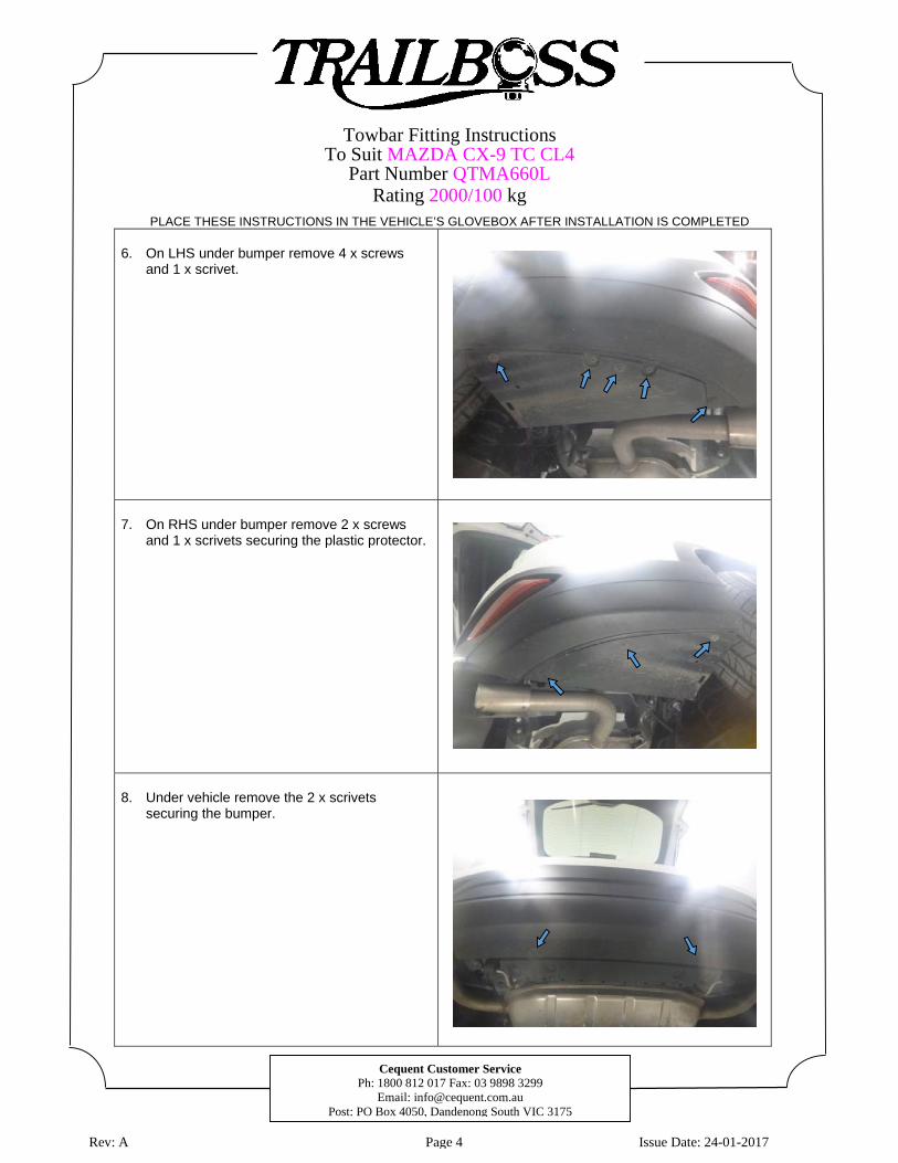
6. On LHS under bumper remove 4 x screws
and 1 x scrivet.
7. On RHS under bumper remove 2 x screws
and 1 x scrivets securing the plastic protector.
8. Under vehicle remove the 2 x scrivets
securing the bumper.
Towbar Fitting Instructions To Suit MAZDA CX-9 TC CL4
Part Number QTMA660L Rating 2000/100 kg
PLACE THESE INSTRUCTIONS IN THE VEHICLE’S GLOVEBOX AFTER INSTALLATION IS COMPLETED
Cequent Customer Service Ph: 1800 812 017 Fax: 03 9898 3299
Email: [email protected] Post: PO Box 4050, Dandenong South VIC 3175
Rev: A Page 5 Issue Date: 24-01-2017
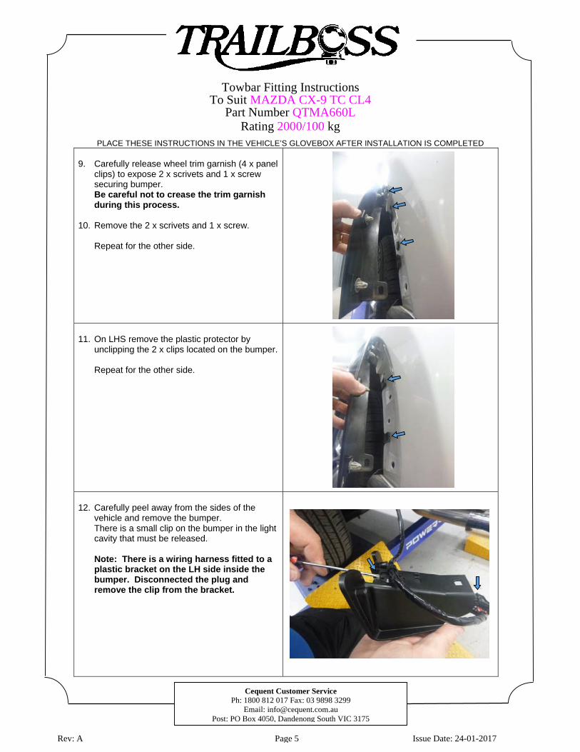
9. Carefully release wheel trim garnish (4 x panel
clips) to expose 2 x scrivets and 1 x screw securing bumper. Be careful not to crease the trim garnish during this process.
10. Remove the 2 x scrivets and 1 x screw.
Repeat for the other side.
11. On LHS remove the plastic protector by
unclipping the 2 x clips located on the bumper.
Repeat for the other side.
12. Carefully peel away from the sides of the
vehicle and remove the bumper. There is a small clip on the bumper in the light cavity that must be released.
Note: There is a wiring harness fitted to a plastic bracket on the LH side inside the bumper. Disconnected the plug and remove the clip from the bracket.
Towbar Fitting Instructions To Suit MAZDA CX-9 TC CL4
Part Number QTMA660L Rating 2000/100 kg
PLACE THESE INSTRUCTIONS IN THE VEHICLE’S GLOVEBOX AFTER INSTALLATION IS COMPLETED
Cequent Customer Service Ph: 1800 812 017 Fax: 03 9898 3299
Email: [email protected] Post: PO Box 4050, Dandenong South VIC 3175
Rev: A Page 6 Issue Date: 24-01-2017
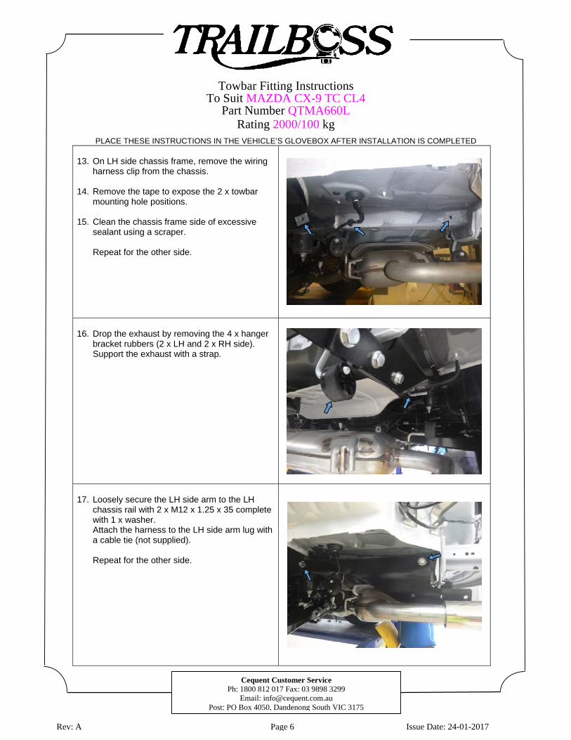
13. On LH side chassis frame, remove the wiring
harness clip from the chassis.
14. Remove the tape to expose the 2 x towbar mounting hole positions.
15. Clean the chassis frame side of excessive
sealant using a scraper.
Repeat for the other side.
16. Drop the exhaust by removing the 4 x hanger
bracket rubbers (2 x LH and 2 x RH side). Support the exhaust with a strap.
17. Loosely secure the LH side arm to the LH
chassis rail with 2 x M12 x 1.25 x 35 complete with 1 x washer. Attach the harness to the LH side arm lug with a cable tie (not supplied).
Repeat for the other side.
Towbar Fitting Instructions To Suit MAZDA CX-9 TC CL4
Part Number QTMA660L Rating 2000/100 kg
PLACE THESE INSTRUCTIONS IN THE VEHICLE’S GLOVEBOX AFTER INSTALLATION IS COMPLETED
Cequent Customer Service Ph: 1800 812 017 Fax: 03 9898 3299
Email: [email protected] Post: PO Box 4050, Dandenong South VIC 3175
Rev: A Page 7 Issue Date: 24-01-2017
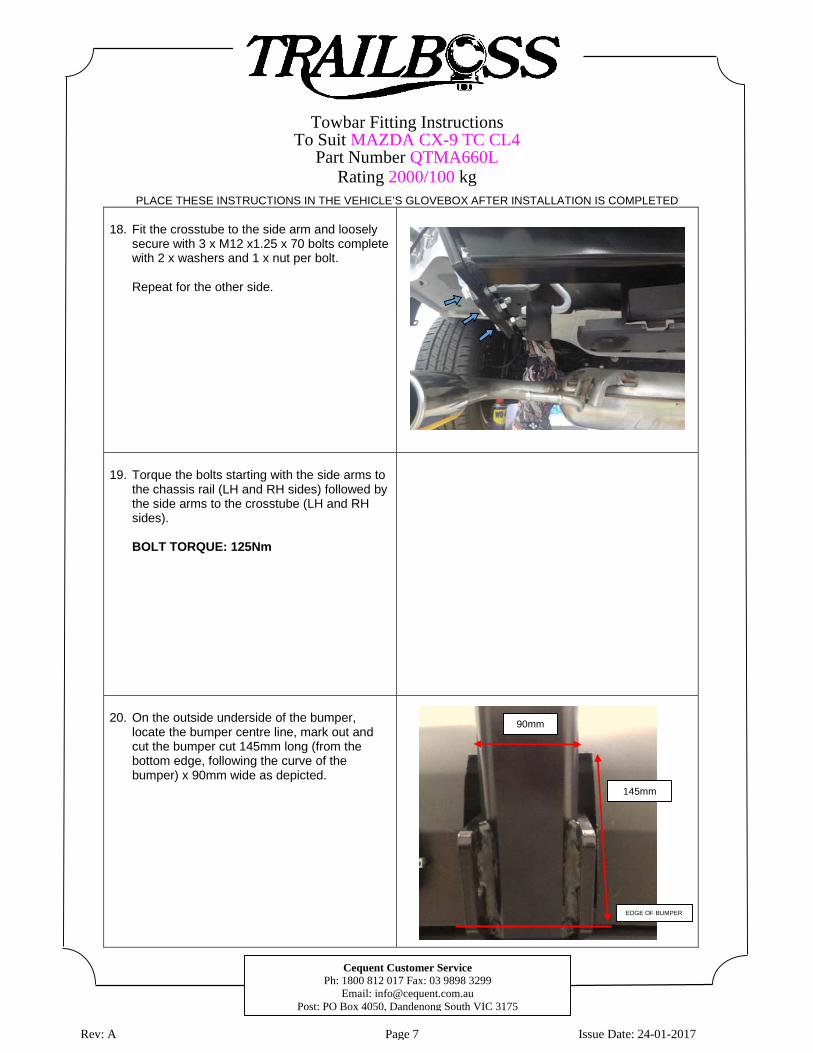
18. Fit the crosstube to the side arm and loosely
secure with 3 x M12 x1.25 x 70 bolts complete with 2 x washers and 1 x nut per bolt.
Repeat for the other side.
19. Torque the bolts starting with the side arms to
the chassis rail (LH and RH sides) followed by the side arms to the crosstube (LH and RH sides).
BOLT TORQUE: 125Nm
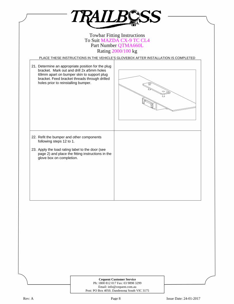
20. On the outside underside of the bumper,
locate the bumper centre line, mark out and cut the bumper cut 145mm long (from the bottom edge, following the curve of the bumper) x 90mm wide as depicted.
90mm
145mm
EDGE OF BUMPER
Towbar Fitting Instructions To Suit MAZDA CX-9 TC CL4
Part Number QTMA660L Rating 2000/100 kg
PLACE THESE INSTRUCTIONS IN THE VEHICLE’S GLOVEBOX AFTER INSTALLATION IS COMPLETED
Cequent Customer Service Ph: 1800 812 017 Fax: 03 9898 3299
Email: [email protected] Post: PO Box 4050, Dandenong South VIC 3175
Rev: A Page 8 Issue Date: 24-01-2017
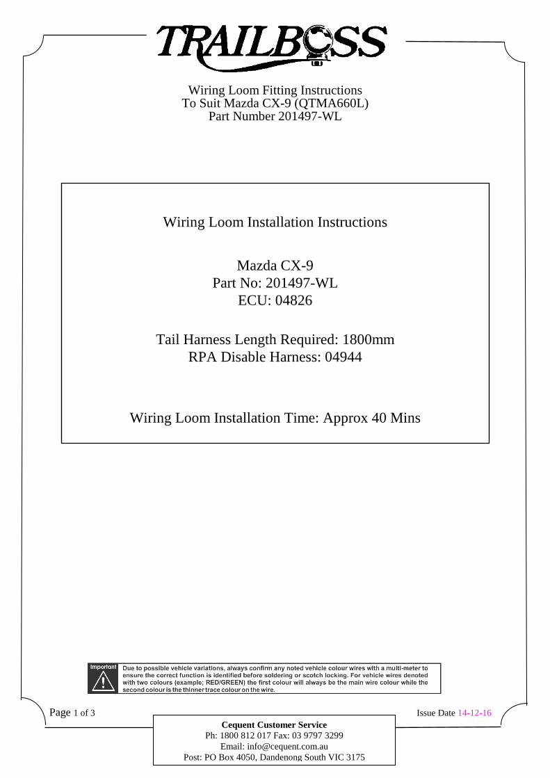
21. Determine an appropriate position for the plug
bracket. Mark out and drill 2x ø5mm holes 69mm apart on bumper skin to support plug bracket. Feed bracket threads through drilled holes prior to reinstalling bumper.
22. Refit the bumper and other components
following steps 12 to 1. 23. Apply the load rating label to the door (see
page 2) and place the fitting instructions in the glove box on completion.
Wiring Loom Fitting Instructions To Suit Mazda CX-9 (QTMA660L)
Part Number 201497-WL
Page 1 of 3 Issue Date 14-12-16 Cequent Customer Service
Ph: 1800 812 017 Fax: 03 9797 3299 Email: [email protected]
Post: PO Box 4050, Dandenong South VIC 3175
Wiring Loom Installation Instructions
Mazda CX-9
Part No: 201497-WL ECU: 04826
Tail Harness Length Required: 1800mm
RPA Disable Harness: 04944
Wiring Loom Installation Time: Approx 40 Mins
Wiring Loom Fitting Instructions To Suit Mazda CX-9 (QTMA660L)
Part Number 201497-WL
Page 2 of 3 Issue Date 14-12-16 Cequent Customer Service
Ph: 1800 812 017 Fax: 03 9797 3299 Email: [email protected]
Post: PO Box 4050, Dandenong South VIC 3175
1. In the luggage compartment, fold down the rear seats.
2. Remove the floor mat and the LHS and RHS floor carpet covers.
3. Unclip and remove both LHS and RHS lower rear quarter storage trays.
4. Remove the luggage compartment rear trim.
5. Remove all the fasteners holding in the LHS and RHS luggage compartment trims (seven on each side) and disconnect the 12V connector from the RHS.
6. Remove both LHS and RHS trims from the vehicle.
7. Remove the RHS upper ‘D’ pillar trim clip and then remove the upper trim.
8. At the rear interior of the vehicle, dislodge the roof lining by removing the two clips.
9. At the exterior RHS rear quarter, remove the grommet sitting lower down from the tail
light.
10. Inside the vehicle, route the trailer patch harness (P/No:201497-WL) break-out connector to the vehicle mating break-out connector.
11. Locate the ground point on the RHS wheel arch area. Secure the trailer patch ground
ring terminal to the vehicle grounding point using the existing vehicle fastener.
12. Using an alcohol wipe (not supplied), clean the sheet metal inner skin exterior side located behind the break out connector and grounding point area. This is where the ECU will be mounted.
13. Connect the trailer patch connector to the ECU (P/No: 04826). Remove the backing
from the back of the ECU and mount the ECU onto the sheet metal area. Ensure ECU is mounted with the connector pointing downwards.
14. Appropriately route the trailer patch terminal branch up along the ‘D’ pillar and into the
head lining.
15. Locate the vehicle harness connectors in the roof lining.
16. Using a multi-meter, locate the reverse wire signal from the vehicle connector.
17. Connect the ezy-tap to the located vehicle wire signal, then connect the trailer patch terminal to the ezy-tap.
18. At the rear exterior of the vehicle, mount the tail harness socket to the towbar mounting
bracket using M4 fasteners (not supplied).
19. Route the tail harness (tail length: 1800mm) across the RHS and up into the exposed grommet hole. Adjust the trailer patch harness grommet so that it is seated correctly and cable tie (not supplied) in place.
Wiring Loom Fitting Instructions To Suit Mazda CX-9 (QTMA660L)
Part Number 201497-WL
Page 3 of 3 Issue Date 14-12-16 Cequent Customer Service
Ph: 1800 812 017 Fax: 03 9797 3299 Email: [email protected]
Post: PO Box 4050, Dandenong South VIC 3175
20. Connect the tail harness 8-way connector to the trailer patch 8-way mating connector.
21. To enable RPA cut-off, crimp the tail harness GREY and GREY/BLACK wires to the
trailer patch mating GREY and GREY/BLACK wires.
22. Test the Trailer Harness function using a light board or multimeter.
23. Secure all harnesses using cable ties (not supplied).
24. Re-fit removed parts and secure all fasteners, ensuring there are no squeaks or rattles.
25. Place the instructions in the glove box after fitment.
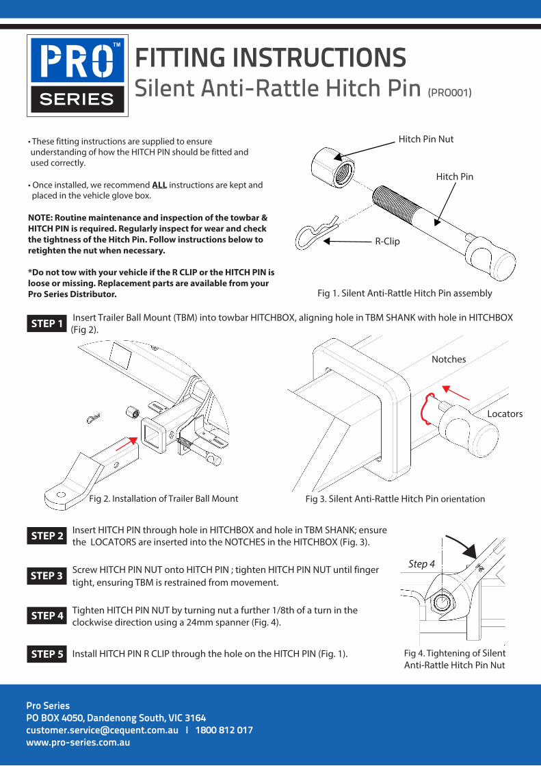
FITTING INSTRUCTIONSSilent Anti-Rattle Hitch Pin (PRO001)
Pro SeriesPO BOX 4050, Dandenong South, VIC 3164 [email protected] I 1800 812 017 www.pro-series.com.au
• These fitting instructions are supplied to ensureunderstanding of how the HITCH PIN should be fitted andused correctly.
• Once installed, we recommend ALL instructions are kept andplaced in the vehicle glove box.
NOTE: Routine maintenance and inspection of the towbar & HITCH PIN is required. Regularly inspect for wear and check the tightness of the Hitch Pin. Follow instructions below to retighten the nut when necessary.
*Do not tow with your vehicle if the R CLIP or the HITCH PIN isloose or missing. Replacement parts are available from your Pro Series Distributor.
Hitch Pin Nut
R-Clip
Hitch Pin
Fig 1. Silent Anti-Rattle Hitch Pin assembly
Fig 2. Installation of Trailer Ball Mount Fig 3. Silent Anti-Rattle Hitch Pin orientation
Insert Trailer Ball Mount (TBM) into towbar HITCHBOX, aligning hole in TBM SHANK with hole in HITCHBOX (Fig 2).
Insert HITCH PIN through hole in HITCHBOX and hole in TBM SHANK; ensure the LOCATORS are inserted into the NOTCHES in the HITCHBOX (Fig. 3).
STEP 1
STEP 2
Screw HITCH PIN NUT onto HITCH PIN ; tighten HITCH PIN NUT until fingerSTEP STEP 3 3 tight, ensuring TBM is restrained from movement.
Tighten HITCH PIN NUT by turning nut a further 1/8th of a turn in the clockwise direction using a 24mm spanner (Fig. 4).
STEP 4
Install HITCH PIN R CLIP through the hole on the HITCH PIN (Fig. 1). STEP 5
Step 4
Fig 4. Tightening of Silent Anti-Rattle Hitch Pin Nut
Notches
Locators
STEP 3
Recommended