TI390F/00/en
Technical Information
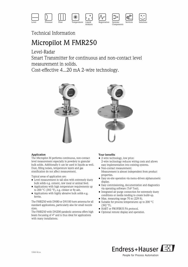
Micropilot M FMR250Level-Radar
Smart Transmitter for continuous and non-contact level
measurement in solids.
Cost-effective 4...20 mA 2-wire technology.
Application
The Micropilot M performs continuous, non-contact
level measurement especially in powdery to granular
bulk solids. Additionally it can be used in liquids as well.
Dust, filling noises, temperature layers and gas
stratification do not affect measurement.
Typical areas of application are:
• Level measurement in tall silos with extremely dusty
bulk solids e.g. cement, raw meal or animal feed.
• Applications with high temperature requirements up
to 200 °C (392 °F), e.g. clinker or fly ash.
• Applications with highly abrasive bulk solids e.g.
ferrite.
The FMR250 with DN80 or DN100 horn antenna for all
standard applications, particularly also for small nozzle
sizes.
The FMR250 with DN200 parabolic antenna offers high
beam focussing of 4° and is thus ideal for applications
with many installations.
Your benefits
• 2-wire technology, low price:
2-wire technology reduces wiring costs and allows
easy implementation into existing systems.
• Non-contact measurement:
Measurement is almost independent from product
properties.
• Easy on-site operation via menu-driven alphanumeric
display.
• Easy commissioning, documentation and diagnostics
via operating software (ToF Tool).
• Integrated air purge connection for extremely dusty
conditions or media tending to create build-up.
• Max. measuring range 70 m (229 ft).
• Suitable for process temperatures up to 200 °C
(392 °F).
• HART or PROFIBUS PA protocol.
• Optional remote display and operation.
Micropilot M
2 Endress + Hauser
Table of contents
Function and system design. . . . . . . . . . . . . . . . . . . . . 3
Measuring principle . . . . . . . . . . . . . . . . . . . . . . . . . . . . . . . . . . . 3
Equipment architecture . . . . . . . . . . . . . . . . . . . . . . . . . . . . . . . . 4
Input . . . . . . . . . . . . . . . . . . . . . . . . . . . . . . . . . . . . . . 7
Measured variable . . . . . . . . . . . . . . . . . . . . . . . . . . . . . . . . . . . . 7
Measuring range . . . . . . . . . . . . . . . . . . . . . . . . . . . . . . . . . . . . . . 7
Measuring conditions . . . . . . . . . . . . . . . . . . . . . . . . . . . . . . . . . . 8
Operating frequency . . . . . . . . . . . . . . . . . . . . . . . . . . . . . . . . . . . 8
Transmitting power . . . . . . . . . . . . . . . . . . . . . . . . . . . . . . . . . . . 8
Output . . . . . . . . . . . . . . . . . . . . . . . . . . . . . . . . . . . . . 9
Output signal . . . . . . . . . . . . . . . . . . . . . . . . . . . . . . . . . . . . . . . . 9
Signal on alarm . . . . . . . . . . . . . . . . . . . . . . . . . . . . . . . . . . . . . . 9
Linearization . . . . . . . . . . . . . . . . . . . . . . . . . . . . . . . . . . . . . . . . 9
Auxiliary energy . . . . . . . . . . . . . . . . . . . . . . . . . . . . . 9
Electrical connection . . . . . . . . . . . . . . . . . . . . . . . . . . . . . . . . . . 9
Cable gland . . . . . . . . . . . . . . . . . . . . . . . . . . . . . . . . . . . . . . . . 10
Terminals . . . . . . . . . . . . . . . . . . . . . . . . . . . . . . . . . . . . . . . . . . 10
Terminal assignment . . . . . . . . . . . . . . . . . . . . . . . . . . . . . . . . . 10
Load HART . . . . . . . . . . . . . . . . . . . . . . . . . . . . . . . . . . . . . . . . 10
Supply voltage . . . . . . . . . . . . . . . . . . . . . . . . . . . . . . . . . . . . . . 11
Cable entry . . . . . . . . . . . . . . . . . . . . . . . . . . . . . . . . . . . . . . . . 11
Power consumption . . . . . . . . . . . . . . . . . . . . . . . . . . . . . . . . . . 11
Current consumption . . . . . . . . . . . . . . . . . . . . . . . . . . . . . . . . . 11
Ripple HART . . . . . . . . . . . . . . . . . . . . . . . . . . . . . . . . . . . . . . . 11
Max. noise HART . . . . . . . . . . . . . . . . . . . . . . . . . . . . . . . . . . . . 11
Overvoltage protector . . . . . . . . . . . . . . . . . . . . . . . . . . . . . . . . . 11
Performance characteristics. . . . . . . . . . . . . . . . . . . . 12
Reference operating conditions . . . . . . . . . . . . . . . . . . . . . . . . . . 12
Maximum measured error . . . . . . . . . . . . . . . . . . . . . . . . . . . . . 12
Resolution . . . . . . . . . . . . . . . . . . . . . . . . . . . . . . . . . . . . . . . . . 12
Reaction time . . . . . . . . . . . . . . . . . . . . . . . . . . . . . . . . . . . . . . . 12
Influence of ambiente temperature . . . . . . . . . . . . . . . . . . . . . . . 12
Operating conditions: Installation . . . . . . . . . . . . . . . 13
Installation instructions . . . . . . . . . . . . . . . . . . . . . . . . . . . . . . . . 13
Beam angle . . . . . . . . . . . . . . . . . . . . . . . . . . . . . . . . . . . . . . . . 14
Installation in vessel FMR250 . . . . . . . . . . . . . . . . . . . . . . . . . . . 15
FMR250 with top target positioner . . . . . . . . . . . . . . . . . . . . . . . 18
Integrated air purge connection . . . . . . . . . . . . . . . . . . . . . . . . . 18
Operating conditions: Environment. . . . . . . . . . . . . . 19
Ambient temperature range . . . . . . . . . . . . . . . . . . . . . . . . . . . . 19
Storage temperature . . . . . . . . . . . . . . . . . . . . . . . . . . . . . . . . . . 19
Climate class . . . . . . . . . . . . . . . . . . . . . . . . . . . . . . . . . . . . . . . 19
Degree of protection . . . . . . . . . . . . . . . . . . . . . . . . . . . . . . . . . . 19
Vibration resistance . . . . . . . . . . . . . . . . . . . . . . . . . . . . . . . . . . 19
Cleaning of the antenna . . . . . . . . . . . . . . . . . . . . . . . . . . . . . . . 19
Electromagnetic compatibility . . . . . . . . . . . . . . . . . . . . . . . . . . . 19
Operating conditions: Process . . . . . . . . . . . . . . . . . . 19
Process temperature range / Process pressure limits . . . . . . . . . . 19
Dielectric constant . . . . . . . . . . . . . . . . . . . . . . . . . . . . . . . . . . . 19
Mechanical construction . . . . . . . . . . . . . . . . . . . . . . 20
Design, dimensions . . . . . . . . . . . . . . . . . . . . . . . . . . . . . . . . . . 20
E+H UNI flange . . . . . . . . . . . . . . . . . . . . . . . . . . . . . . . . . . . . . 22
Weight . . . . . . . . . . . . . . . . . . . . . . . . . . . . . . . . . . . . . . . . . . . 23
Material . . . . . . . . . . . . . . . . . . . . . . . . . . . . . . . . . . . . . . . . . . . 23
Process connection . . . . . . . . . . . . . . . . . . . . . . . . . . . . . . . . . . 23
Seal . . . . . . . . . . . . . . . . . . . . . . . . . . . . . . . . . . . . . . . . . . . . . . 23
Antenna . . . . . . . . . . . . . . . . . . . . . . . . . . . . . . . . . . . . . . . . . . . 23
Human interface . . . . . . . . . . . . . . . . . . . . . . . . . . . . 24
Operation concept . . . . . . . . . . . . . . . . . . . . . . . . . . . . . . . . . . . 24
Display elements . . . . . . . . . . . . . . . . . . . . . . . . . . . . . . . . . . . . 24
Operating elements . . . . . . . . . . . . . . . . . . . . . . . . . . . . . . . . . . 25
On-site operation . . . . . . . . . . . . . . . . . . . . . . . . . . . . . . . . . . . . 26
Remote operation . . . . . . . . . . . . . . . . . . . . . . . . . . . . . . . . . . . . 27
Certificates and approvals . . . . . . . . . . . . . . . . . . . . . 28
CE approval . . . . . . . . . . . . . . . . . . . . . . . . . . . . . . . . . . . . . . . . 28
Ex approval . . . . . . . . . . . . . . . . . . . . . . . . . . . . . . . . . . . . . . . . 28
External standards and guidelines . . . . . . . . . . . . . . . . . . . . . . . . 28
RF approvals . . . . . . . . . . . . . . . . . . . . . . . . . . . . . . . . . . . . . . . 28
Ordering information. . . . . . . . . . . . . . . . . . . . . . . . . 29
Micropilot M FMR250 . . . . . . . . . . . . . . . . . . . . . . . . . . . . . . . . 29
Accessories . . . . . . . . . . . . . . . . . . . . . . . . . . . . . . . . 32
Weather protection cover . . . . . . . . . . . . . . . . . . . . . . . . . . . . . . 32
Remote display FHX40 . . . . . . . . . . . . . . . . . . . . . . . . . . . . . . . . 32
Commubox FXA191 HART . . . . . . . . . . . . . . . . . . . . . . . . . . . . 33
Commubox FXA195 HART . . . . . . . . . . . . . . . . . . . . . . . . . . . . 33
Service Interface FXA193 . . . . . . . . . . . . . . . . . . . . . . . . . . . . . . 33
Documentation . . . . . . . . . . . . . . . . . . . . . . . . . . . . . 34
System Information . . . . . . . . . . . . . . . . . . . . . . . . . . . . . . . . . . 34
Technical Information . . . . . . . . . . . . . . . . . . . . . . . . . . . . . . . . 34
Operating Instructions . . . . . . . . . . . . . . . . . . . . . . . . . . . . . . . . 34
Certificates . . . . . . . . . . . . . . . . . . . . . . . . . . . . . . . . . . . . . . . . 34
Micropilot M
Endress + Hauser 3
Function and system design
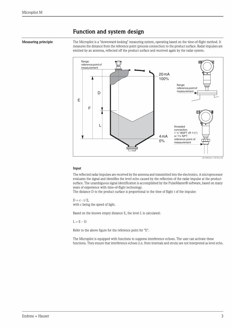
Measuring principle The Micropilot is a "downward-looking" measuring system, operating based on the time-of-flight method. It
measures the distance from the reference point (process connection) to the product surface. Radar impulses are
emitted by an antenna, reflected off the product surface and received again by the radar system.
L00-FMR250xx-15-00-00-en-001
Input
The reflected radar impulses are received by the antenna and transmitted into the electronics. A microprocessor
evaluates the signal and identifies the level echo caused by the reflection of the radar impulse at the product
surface. The unambiguous signal identification is accomplished by the PulseMaster® software, based on many
years of experience with time-of-flight technology.
The distance D to the product surface is proportional to the time of flight t of the impulse:
D = c · t/2,
with c being the speed of light.
Based on the known empty distance E, the level L is calculated:
L = E – D
Refer to the above figure for the reference point for "E".
The Micropilot is equipped with functions to suppress interference echoes. The user can activate these
functions. They ensure that interference echoes (i.e. from internals and struts) are not interpreted as level echo.
20mA100%
4mA0%
D
L
F
E
flange:reference point ofmeasurement
flange:reference point ofmeasurement
threadedconnection1 ½” (R 1
:reference point ofmeasurement
BSPT ½”)or 1½ NPT
Micropilot M
4 Endress + Hauser
Output
The Micropilot is commissioned by entering an empty distance E (=zero), a full distance F (=span) and an
application parameter. The application parameter automatically adapts the instrument to the process
conditions. The data points “E” and “F” correspond with 4mA and 20mA for instruments with current output.
They correspond with 0 % and 100 % for digital outputs and the display module.
A linearization with max. 32 points, based on a table entered either manually or semi-automatically, can be
activated locally or remotely. This function provides a measurement in engineering units and a linear output
signal for spheres, horizontal cylindrical tanks and vessels with conical outlet.
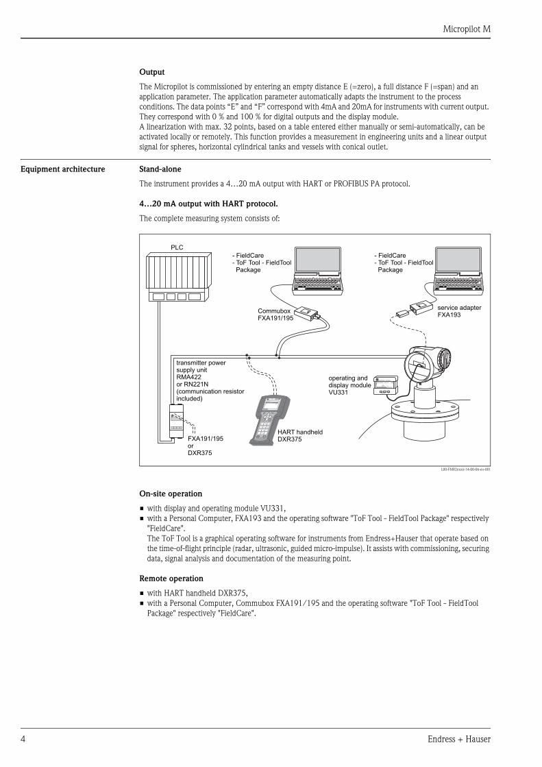
Equipment architecture Stand-alone
The instrument provides a 4…20 mA output with HART or PROFIBUS PA protocol.
4…20 mA output with HART protocol.
The complete measuring system consists of:
L00-FMR2xxxx-14-00-06-en-001
On-site operation
• with display and operating module VU331,
• with a Personal Computer, FXA193 and the operating software "ToF Tool - FieldTool Package" respectively
"FieldCare".
The ToF Tool is a graphical operating software for instruments from Endress+Hauser that operate based on
the time-of-flight principle (radar, ultrasonic, guided micro-impulse). It assists with commissioning, securing
data, signal analysis and documentation of the measuring point.
Remote operation
• with HART handheld DXR375,
• with a Personal Computer, Commubox FXA191/195 and the operating software "ToF Tool - FieldTool
Package" respectively "FieldCare".
ENDRESS + HAUSER
E+–
%
ENDRESS + HAUSERRMA 422
1# % &
Copy
G H I
P Q R S
, ( ) ‘
A B C
Paste
PageOn
PageUp
DeleteBksp
Insert
J K L
T U V
_ < >
D E F
Hot Key
+ Hot Key
M N O
W X Y Z
+ * /
4
7
.
2
5
8
0
375FIELD COMMUNICATOR
3
6
9
-
DELTABAR: * * * * * * * *ONLINE
1 QUICK SETUP2 OPERATING MENU
4 SV 0 °C3 PV 352 mbar
HELP SAVE
dsdmdmdf das.
asdas faasas la.
- FieldCare- ToF Tool - FieldToolPackage
- FieldCare- ToF Tool - FieldToolPackage
HART handheldDXR375FXA191/195
orDXR375
transmitter powersupply unitRMA422or RN221N(communication resistorincluded)
PLC
CommuboxFXA191/195
operating anddisplay moduleVU331
service adapterFXA193
Micropilot M
Endress + Hauser 5
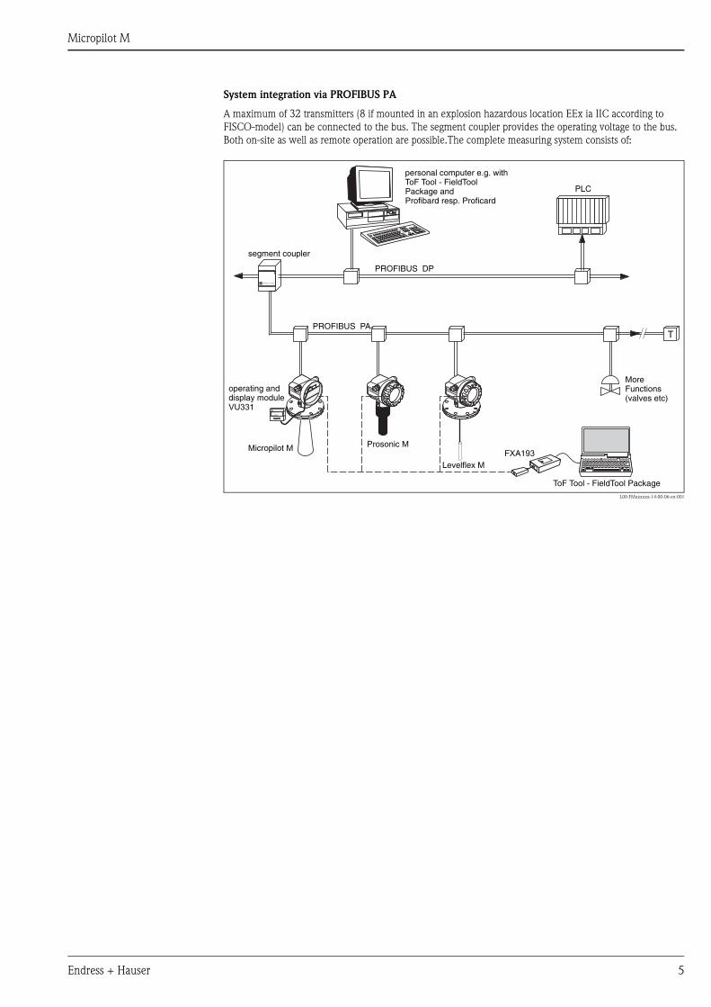
System integration via PROFIBUS PA
A maximum of 32 transmitters (8 if mounted in an explosion hazardous location EEx ia IIC according to
FISCO-model) can be connected to the bus. The segment coupler provides the operating voltage to the bus.
Both on-site as well as remote operation are possible.The complete measuring system consists of:
L00-FMxxxxxx-14-00-06-en-001
ENDRESS + HAUSER
FXA193Micropilot M Prosonic M
Levelflex M
ENDRESS + HAUSER
E+–
%
T
PROFIBUS DP
PROFIBUS PA
ToF Tool - FieldTool Package
personal computer e.g. withToF Tool - FieldToolPackage andProfibard resp. Proficard
segment coupler
PLC
operating anddisplay moduleVU331
MoreFunctions(valves etc)
Micropilot M
6 Endress + Hauser
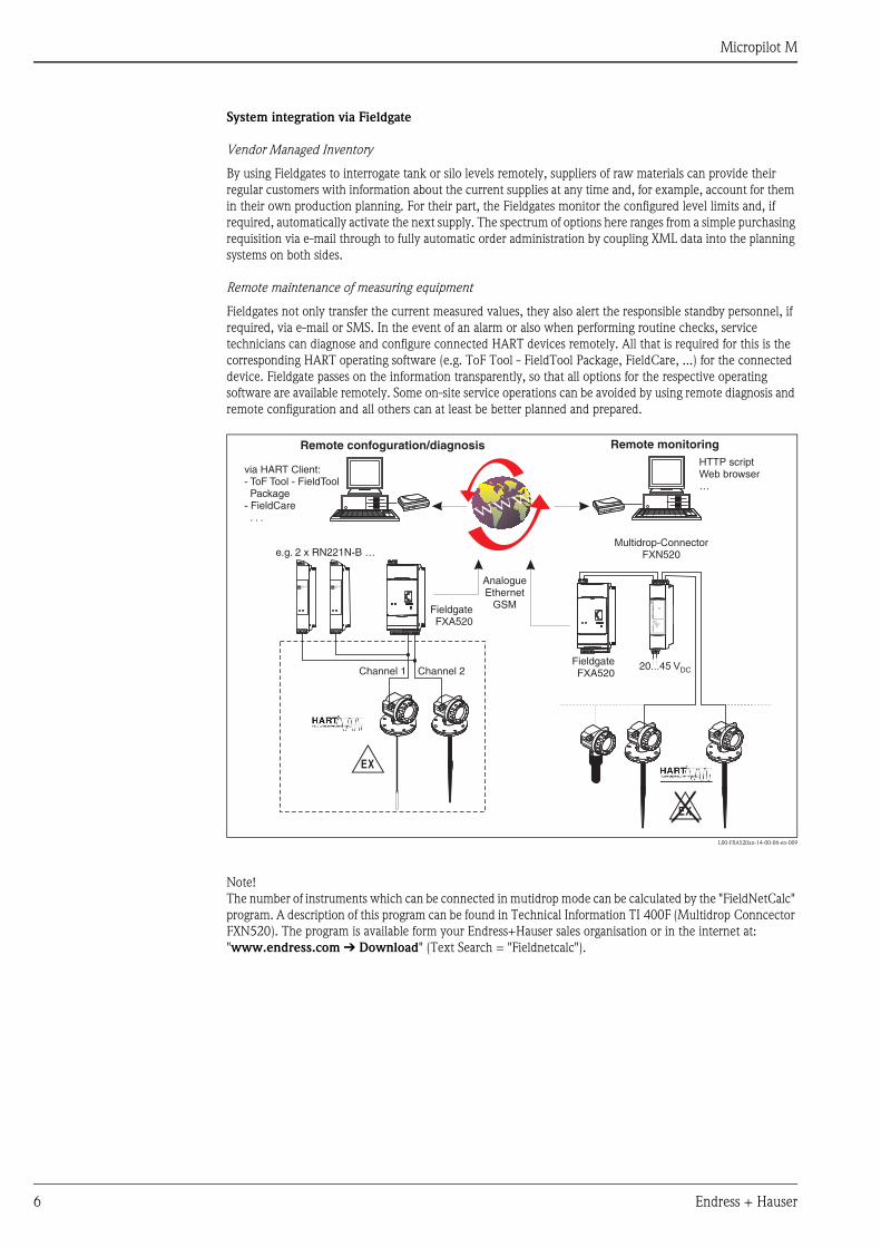
System integration via Fieldgate
Vendor Managed Inventory
By using Fieldgates to interrogate tank or silo levels remotely, suppliers of raw materials can provide their
regular customers with information about the current supplies at any time and, for example, account for them
in their own production planning. For their part, the Fieldgates monitor the configured level limits and, if
required, automatically activate the next supply. The spectrum of options here ranges from a simple purchasing
requisition via e-mail through to fully automatic order administration by coupling XML data into the planning
systems on both sides.
Remote maintenance of measuring equipment
Fieldgates not only transfer the current measured values, they also alert the responsible standby personnel, if
required, via e-mail or SMS. In the event of an alarm or also when performing routine checks, service
technicians can diagnose and configure connected HART devices remotely. All that is required for this is the
corresponding HART operating software (e.g. ToF Tool - FieldTool Package, FieldCare, ...) for the connected
device. Fieldgate passes on the information transparently, so that all options for the respective operating
software are available remotely. Some on-site service operations can be avoided by using remote diagnosis and
remote configuration and all others can at least be better planned and prepared.
L00-FXA520xx-14-00-06-en-009
Note!
The number of instruments which can be connected in mutidrop mode can be calculated by the "FieldNetCalc"
program. A description of this program can be found in Technical Information TI 400F (Multidrop Conncector
FXN520). The program is available form your Endress+Hauser sales organisation or in the internet at:
"www.endress.com É Download" (Text Search = "Fieldnetcalc").
-
FieldgateFXA520
ENDRESS+HAUSERRN 221N
ENDRESS+HAUSERRN 221N
.
FieldgateFXA520
20...45 VDC
FX
N520
FX
N520
Multidrop-ConnectorFXN520
HTTP scriptWeb browser…
AnalogueEthernet
GSM
e.g. 2 x RN221N-B …
Channel 1 Channel 2
via HART Client:- ToF Tool - FieldToolPackage
- FieldCare. . .
Remote monitoringRemote confoguration/diagnosis
Micropilot M
Endress + Hauser 7
Input
Measured variable The measured variable is the distance between a reference point (refer to fig. on page 2) and a reflective surface
(i.e. medium surface).
The level is calculated based on the vessel height entered.The level can be converted into other units (volume,
mass) by means of a linearization (32 points).
Measuring range The usable measuring range depends on the size of the antenna, the reflectivity of the medium, the mounting
location and eventual interference reflections. The maximum configurable range is 70 m (229 ft) for
Micropilot M FMR250.
Reduction of the max. possible measuring range through:
• Media with poor reflection properties (= small DC). For examples refer to table 1.
• Angle of repose.
• Extremely loose surfaces of bulk solids, e.g. bulk solids with low bulk weight for pneumatic filling.
• Build-up, above all of moist products.
Table 1:
The following table describes the media groups and the dielectric constant εr.
The respective lower group applies for very loose or loosened bulk solids.
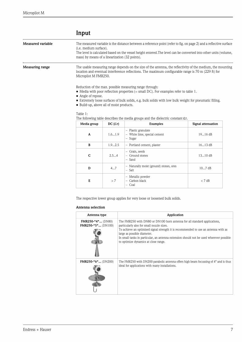
Antenna selection
Media group DC (εr) Examples Signal attenuation
A 1.6...1.9
– Plastic granulate
– White lime, special cement
– Sugar
19...16 dB
B 1.9...2.5 – Portland cement, plaster 16...13 dB
C 2.5...4
– Grain, seeds
– Ground stones
– Sand
13...10 dB
D 4...7– Naturally moist (ground) stones, ores
– Salt10...7 dB
E > 7
– Metallic powder
– Carbon black
– Coal
< 7 dB
Antenna type Application
FMR250-*4*... (DN80)
FMR250-*5*... (DN100)
The FMR250 with DN80 or DN100 horn antenna for all standard applications,
particularly also for small nozzle sizes.
To achieve an optimised signal strength it is recommended to use an antenna with as
large as possible diameter.
In small tanks in particular, an antenna extension should not be used wherever possible
to optimize dynamics at close range.
FMR250-*6*... (DN200) The FMR250 with DN200 parabolic antenna offers high beam focussing of 4° and is thus
ideal for applications with many installations.
Micropilot M
8 Endress + Hauser
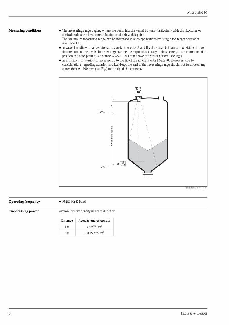
Measuring conditions • The measuring range begins, where the beam hits the vessel bottom. Particularly with dish bottoms or
conical outlets the level cannot be detected below this point.
The maximum measuring range can be increased in such applications by using a top target positioner
(see Page 13).
• In case of media with a low dielectric constant (groups A and B), the vessel bottom can be visible through
the medium at low levels. In order to guarantee the required accuracy in these cases, it is recommended to
position the zero-point at a distance C =50...150 mm above the vessel bottom (see Fig.).
• In principle it is possible to measure up to the tip of the antenna with FMR250. However, due to
considerations regarding abrasion and build-up, the end of the measuring range should not be chosen any
closer than A=400 mm (see Fig.) to the tip of the antenna.
L00-FMR250xx-17-00-00-en-001
Operating frequency • FMR250: K-band
Transmitting power Average energy density in beam direction:
100%
0%
A
C
Me
asu
rin
g r
an
ge
Distance Average energy density
1 m < 4 nW/cm2
5 m < 0,16 nW/cm2
Micropilot M
Endress + Hauser 9
Output
Output signal • 4…20 mA with HART protocol
• PROFIBUS PA
Signal on alarm Error information can be accessed via the following interfaces:
• Local display:
– Error symbol
– Plain text display
• Current output
• Digital interface
Linearization The linearization function of the Micropilot M allows the conversion of the measured value into any unit of
length or volume. Linearization tables for calculating the volume in cylindrical vessels are pre-programmed.
Other tables of up to 32 value pairs can be entered manually or semi-automatically.
Auxiliary energy
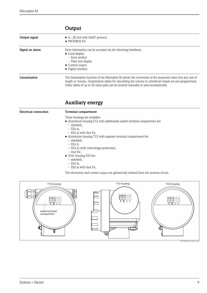
Electrical connection Terminal compartment
Three housings are available:
• Aluminium housing F12 with additionally sealed terminal compartment for:
– standard,
– EEx ia,
– EEx ia with dust Ex.
• Aluminium housing T12 with separate terminal compartment for:
– standard,
– EEx d,
– EEx ia (with overvoltage protection),
– dust Ex.
• 316L housing F23 for:
– standard,
– EEx ia,
– EEx ia with dust Ex.
The electronics and current output are galvanically isolated from the antenna circuit.
L00-FMR2xxxx-04-00-00-en-019
1 12 23 34 41 2 3 4
sealed terminalcompartment
F12 housing F23 housingT12 housing
Micropilot M
10 Endress + Hauser
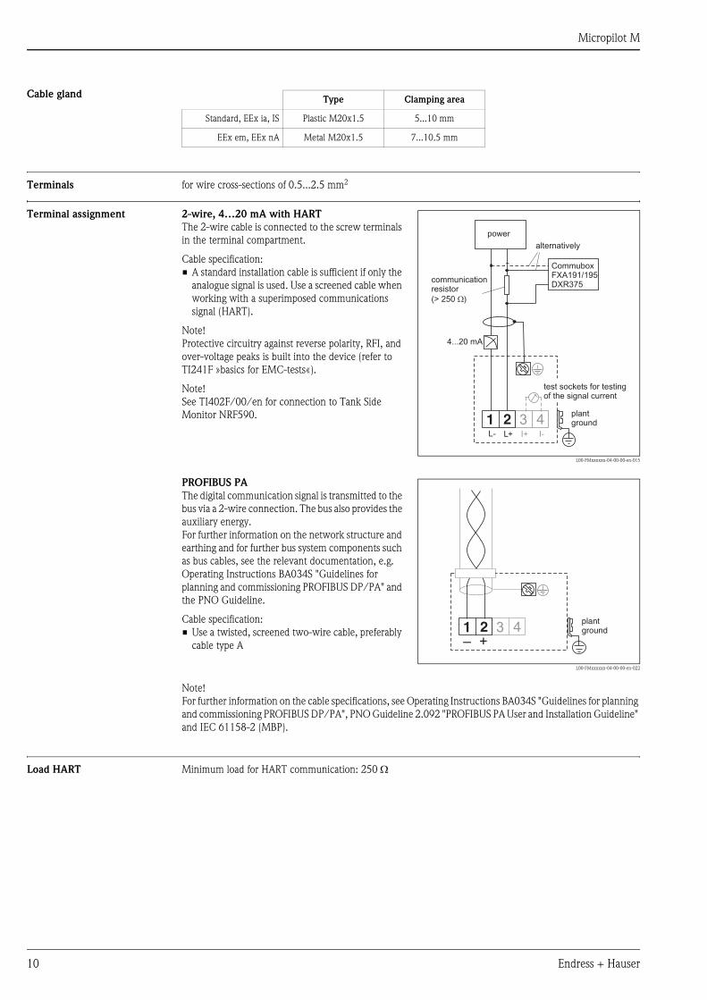
Cable gland
Terminals for wire cross-sections of 0.5...2.5 mm2
Terminal assignment
Load HART Minimum load for HART communication: 250 Ω
Type Clamping area
Standard, EEx ia, IS Plastic M20x1.5 5...10 mm
EEx em, EEx nA Metal M20x1.5 7...10.5 mm
2-wire, 4…20 mA with HART
The 2-wire cable is connected to the screw terminals
in the terminal compartment.
Cable specification:
• A standard installation cable is sufficient if only the
analogue signal is used. Use a screened cable when
working with a superimposed communications
signal (HART).
Note!
Protective circuitry against reverse polarity, RFI, and
over-voltage peaks is built into the device (refer to
TI241F »basics for EMC-tests«).
Note!
See TI402F/00/en for connection to Tank Side
Monitor NRF590.
L00-FMxxxxxx-04-00-00-en-015
3 4I+ I-
1 2L- L+
4...20 mA
CommuboxFXA191/195DXR375
communicationresistor
(> 250 )W
alternatively
plantground
test sockets for testingof the signal current
power
PROFIBUS PA
The digital communication signal is transmitted to the
bus via a 2-wire connection. The bus also provides the
auxiliary energy.
For further information on the network structure and
earthing and for further bus system components such
as bus cables, see the relevant documentation, e.g.
Operating Instructions BA034S "Guidelines for
planning and commissioning PROFIBUS DP/PA" and
the PNO Guideline.
Cable specification:
• Use a twisted, screened two-wire cable, preferably
cable type A
L00-FMxxxxxx-04-00-00-en-022
Note!
For further information on the cable specifications, see Operating Instructions BA034S "Guidelines for planning
and commissioning PROFIBUS DP/PA", PNO Guideline 2.092 "PROFIBUS PA User and Installation Guideline"
and IEC 61158-2 (MBP).
3 41 2+–
plantground
Micropilot M
Endress + Hauser 11
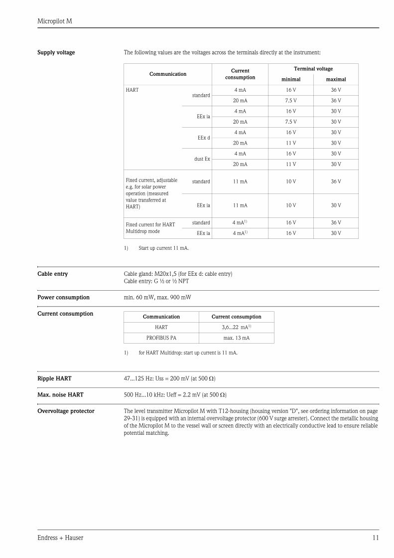
Supply voltage The following values are the voltages across the terminals directly at the instrument:
Cable entry Cable gland: M20x1,5 (for EEx d: cable entry)
Cable entry: G ½ or ½ NPT
Power consumption min. 60 mW, max. 900 mW
Current consumption
Ripple HART 47...125 Hz: Uss = 200 mV (at 500 Ω)
Max. noise HART 500 Hz...10 kHz: Ueff = 2.2 mV (at 500 Ω)
Overvoltage protector The level transmitter Micropilot M with T12-housing (housing version "D", see ordering information on page
29-31) is equipped with an internal overvoltage protector (600 V surge arrester). Connect the metallic housing
of the Micropilot M to the vessel wall or screen directly with an electrically conductive lead to ensure reliable
potential matching.
CommunicationCurrent
consumption
Terminal voltage
minimal maximal
HARTstandard
4 mA 16 V 36 V
20 mA 7.5 V 36 V
EEx ia4 mA 16 V 30 V
20 mA 7.5 V 30 V
EEx d4 mA 16 V 30 V
20 mA 11 V 30 V
dust Ex4 mA 16 V 30 V
20 mA 11 V 30 V
Fixed current, adjustable
e.g. for solar power
operation (measured
value transferred at
HART)
standard 11 mA 10 V 36 V
EEx ia 11 mA 10 V 30 V
Fixed current for HART
Multidrop mode
standard 4 mA1)
1) Start up current 11 mA.
16 V 36 V
EEx ia 4 mA1) 16 V 30 V
Communication Current consumption
HART 3,6...22 mA1)
1) for HART Multidrop: start up current is 11 mA.
PROFIBUS PA max. 13 mA
Micropilot M
12 Endress + Hauser
Performance characteristics
Reference operating
conditions
• temperature = +20 °C (68 °F) ±5 °C (9 °F)
• pressure = 1013 mbar abs. (14.7 psia) ±20 mbar (0.3 psi)
• relative humidity (air) = 65 % ±20%
• ideal reflector
• no major interference reflections inside the signal beam
Maximum measured error Typical statements for reference conditions, include linearity, repeatability, and hysteresis:
• up to 1 m: ±30 mm
• ex 1 m: ±15 mm (or 0.04% of measuring range, whatever is larger)
Resolution Digital / analog in % 4…20 mA
• FMR250: 1mm / 0.03 % of measuring range
Reaction time The reaction time depends on the parameter settings (min. 1 s). In case of fast level changes, the instrument
needs the reaction time to indicate the new value.
Influence of ambiente
temperature
The measurements are carried out in accordance with EN 61298-3:
• digital output (HART, PROFIBUS PA):
– FMR250
average TK: 5 mm/10 K, max. 15 mm over the entire temperature range -40 °C...+80 °C
• Current output (additional error, in reference to the span of 16 mA):
– Zero point (4 mA)
average TK: 0,03 %/10 K, max. 0,45 % over the entire temperature range -40 °C...+80 °C
– Span (20 mA)
average TK: 0,09 %/10 K, max. 0,95 % over the entire temperature range -40 °C...+80 °C
Micropilot M
Endress + Hauser 13
Operating conditions: Installation
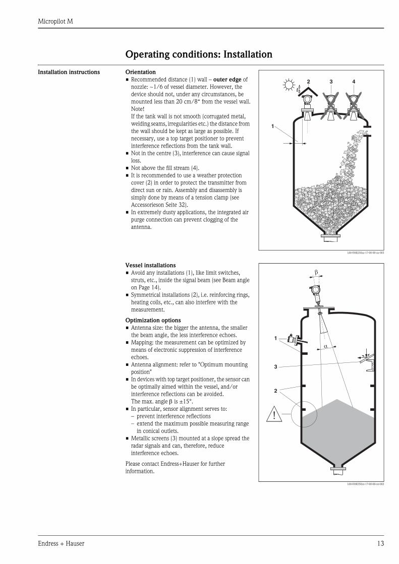
Installation instructions Orientation
• Recommended distance (1) wall – outer edge of
nozzle: ~1/6 of vessel diameter. However, the
device should not, under any circumstances, be
mounted less than 20 cm/8“ from the vessel wall.
Note!
If the tank wall is not smooth (corrugated metal,
welding seams, irregularities etc.) the distance from
the wall should be kept as large as possible. If
necessary, use a top target positioner to prevent
interference reflections from the tank wall.
• Not in the centre (3), interference can cause signal
loss.
• Not above the fill stream (4).
• It is recommended to use a weather protection
cover (2) in order to protect the transmitter from
direct sun or rain. Assembly and disassembly is
simply done by means of a tension clamp (see
Accessorieson Seite 32).
• In extremely dusty applications, the integrated air
purge connection can prevent clogging of the
antenna.
L00-FMR250xx-17-00-00-xx-003
1
2 3 4
Vessel installations
• Avoid any installations (1), like limit switches,
struts, etc., inside the signal beam (see Beam angle
on Page 14).
• Symmetrical installations (2), i.e. reinforcing rings,
heating coils, etc., can also interfere with the
measurement.
Optimization options
• Antenna size: the bigger the antenna, the smaller
the beam angle, the less interference echoes.
• Mapping: the measurement can be optimized by
means of electronic suppression of interference
echoes.
• Antenna alignment: refer to "Optimum mounting
position"
• In devices with top target positioner, the sensor can
be optimally aimed within the vessel, and/or
interference reflections can be avoided.
The max. angle β is ±15°.
• In particular, sensor alignment serves to:
– prevent interference reflections
– extend the maximum possible measuring range
in conical outlets.
• Metallic screens (3) mounted at a slope spread the
radar signals and can, therefore, reduce
interference echoes.
Please contact Endress+Hauser for further
information.
L00-FMR250xx-17-00-00-xx-002
1
2
a
b
3
Micropilot M
14 Endress + Hauser
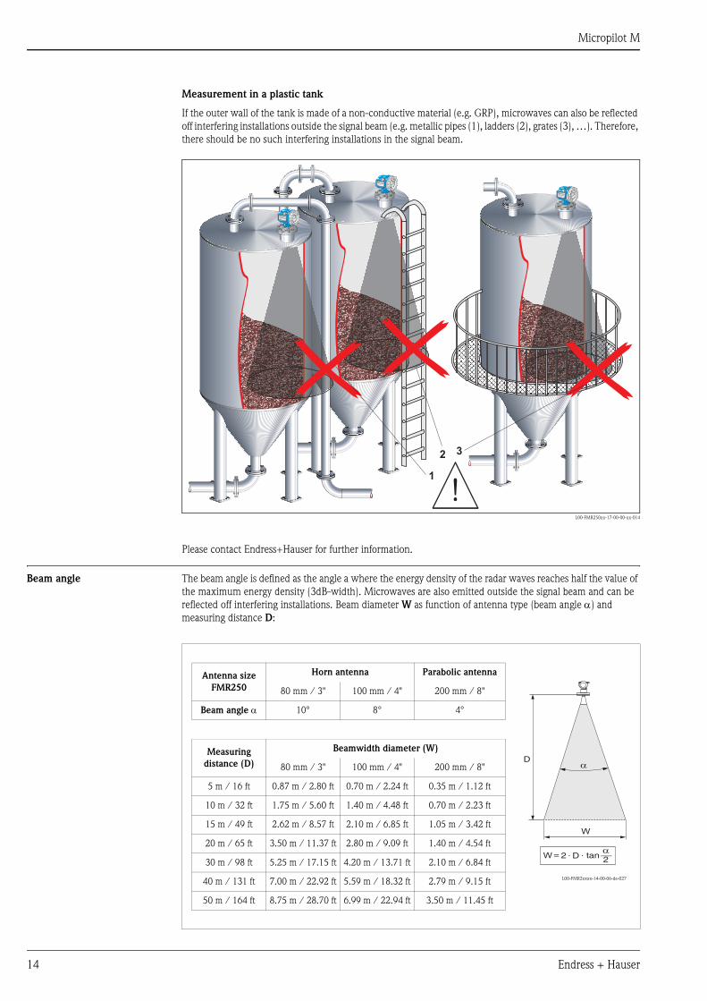
Measurement in a plastic tank
If the outer wall of the tank is made of a non-conductive material (e.g. GRP), microwaves can also be reflected
off interfering installations outside the signal beam (e.g. metallic pipes (1), ladders (2), grates (3), …). Therefore,
there should be no such interfering installations in the signal beam.
L00-FMR250xx-17-00-00-xx-014
Please contact Endress+Hauser for further information.
Beam angle The beam angle is defined as the angle a where the energy density of the radar waves reaches half the value of
the maximum energy density (3dB-width). Microwaves are also emitted outside the signal beam and can be
reflected off interfering installations. Beam diameter W as function of antenna type (beam angle α) and
measuring distance D:
VH
00
VH
00
Endress+Hauser
Endress+Hauser
- + V H
ENDRESS+HAUSERMICROPILOT II
IP 65
Order Code:Ser.-No.:
MessbereichMeasuring rangeU 16...36 V DC4...20 mA
max. 20 m
Ma
de
in G
erm
any
Ma
ulb
urg
Ma
de
in G
erm
any
Ma
ulb
urg
T >70°C :At >85°C
VH
00
VH
00
Endress+Hauser
Endress+Hauser
- + V H
ENDRESS+HAUSERMICROPILOT II
IP 65
Order Code:Ser.-No.:
MessbereichMeasuring rangeU 16...36 V DC4...20 mA
max. 20 m
Ma
de
in G
erm
any
Ma
ulb
urg
Ma
de
in G
erm
any
Ma
ulb
urg
T >70°C :At >85°C
1
2 3
VH
00
VH
00
Endress+Hauser
Endress+Hauser
- + V H
ENDRESS+HAUSERMICROPILOT II
IP 65
Order Code:Ser.-No.:
MessbereichMeasuring rangeU 16...36 V DC4...20 mA
max. 20 m
Ma
de
in G
erm
any
Ma
ulb
urg
Ma
de
in G
erm
any
Ma
ulb
urg
T >70°C :At >85°C
Antenna size
FMR250
Horn antenna Parabolic antenna
L00-FMR2xxxx-14-00-06-de-027
80 mm / 3" 100 mm / 4" 200 mm / 8"
Beam angle α 10° 8° 4°
Measuring
distance (D)
Beamwidth diameter (W)
80 mm / 3" 100 mm / 4" 200 mm / 8"
5 m / 16 ft 0.87 m / 2.80 ft 0.70 m / 2.24 ft 0.35 m / 1.12 ft
10 m / 32 ft 1.75 m / 5.60 ft 1.40 m / 4.48 ft 0.70 m / 2.23 ft
15 m / 49 ft 2.62 m / 8.57 ft 2.10 m / 6.85 ft 1.05 m / 3.42 ft
20 m / 65 ft 3.50 m / 11.37 ft 2.80 m / 9.09 ft 1.40 m / 4.54 ft
30 m / 98 ft 5.25 m / 17.15 ft 4.20 m / 13.71 ft 2.10 m / 6.84 ft
40 m / 131 ft 7.00 m / 22.92 ft 5.59 m / 18.32 ft 2.79 m / 9.15 ft
50 m / 164 ft 8.75 m / 28.70 ft 6.99 m / 22.94 ft 3.50 m / 11.45 ft
aD
W
aD _=
22 . . tanW
Micropilot M
Endress + Hauser 15
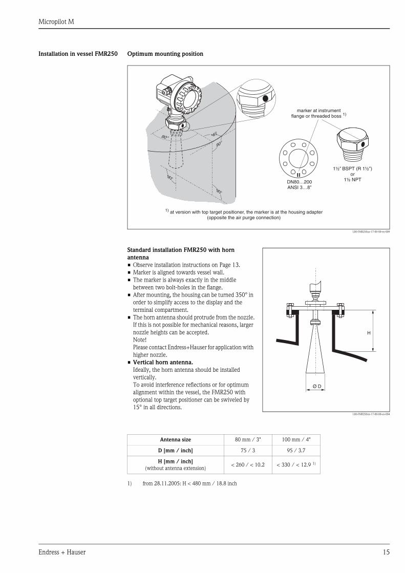
Installation in vessel FMR250 Optimum mounting position
L00-FMR250xx-17-00-00-en-009
90°
90°
90°
90°
90°
90°
90°
90°
9
DN80…200ANSI 3…8”
90°
1½” BSPT (R 1½”)or
1½ NPT
marker at instrumentflange or threaded boss 1)
1) at version with top target positioner, the marker is at the housing adapter(opposite the air purge connection)
Standard installation FMR250 with horn
antenna
• Observe installation instructions on Page 13.
• Marker is aligned towards vessel wall.
• The marker is always exactly in the middle
between two bolt-holes in the flange.
• After mounting, the housing can be turned 350° in
order to simplify access to the display and the
terminal compartment.
• The horn antenna should protrude from the nozzle.
If this is not possible for mechanical reasons, larger
nozzle heights can be accepted.
Note!
Please contact Endress+Hauser for application with
higher nozzle.
• Vertical horn antenna.
Ideally, the horn antenna should be installed
vertically.
To avoid interference reflections or for optimum
alignment within the vessel, the FMR250 with
optional top target positioner can be swiveled by
15° in all directions.L00-FMR250xx-17-00-00-en-004
H
Ø D
Antenna size 80 mm / 3" 100 mm / 4"
D [mm / inch] 75 / 3 95 / 3.7
H [mm / inch]
(without antenna extension)< 260 / < 10.2 < 330 / < 12.9 1)
1) from 28.11.2005: H < 480 mm / 18.8 inch
Micropilot M
16 Endress + Hauser
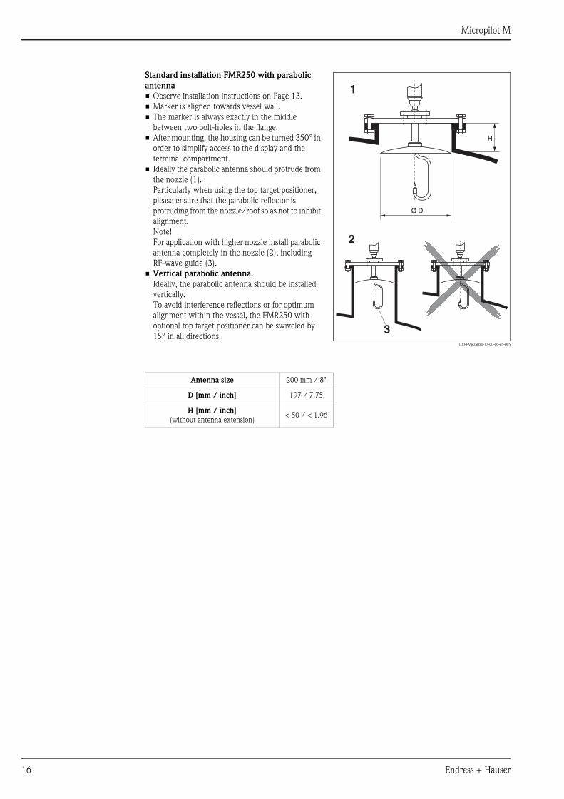
Standard installation FMR250 with parabolic
antenna
• Observe installation instructions on Page 13.
• Marker is aligned towards vessel wall.
• The marker is always exactly in the middle
between two bolt-holes in the flange.
• After mounting, the housing can be turned 350° in
order to simplify access to the display and the
terminal compartment.
• Ideally the parabolic antenna should protrude from
the nozzle (1).
Particularly when using the top target positioner,
please ensure that the parabolic reflector is
protruding from the nozzle/roof so as not to inhibit
alignment.
Note!
For application with higher nozzle install parabolic
antenna completely in the nozzle (2), including
RF-wave guide (3).
• Vertical parabolic antenna.
Ideally, the parabolic antenna should be installed
vertically.
To avoid interference reflections or for optimum
alignment within the vessel, the FMR250 with
optional top target positioner can be swiveled by
15° in all directions.L00-FMR250xx-17-00-00-en-005
H
Ø D
1
2
3
Antenna size 200 mm / 8"
D [mm / inch] 197 / 7.75
H [mm / inch]
(without antenna extension)< 50 / < 1.96
Micropilot M
Endress + Hauser 17
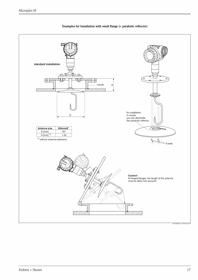
Examples for installation with small flange (< parabolic reflector)
L00-FMR250xx-17-00-00-en-007
HD
D [mm]200mm/8”
197
< 50H [mm] 1)
for installationin nozzleyou can dismantlethe parabolic reflector
4 bolts
standard installation
nozzle
Antenna size
Caution!At hinged flanges, the length of the antennamust be taken into account!
1) without antenna extension
Micropilot M
18 Endress + Hauser
FMR250 with top target
positioner
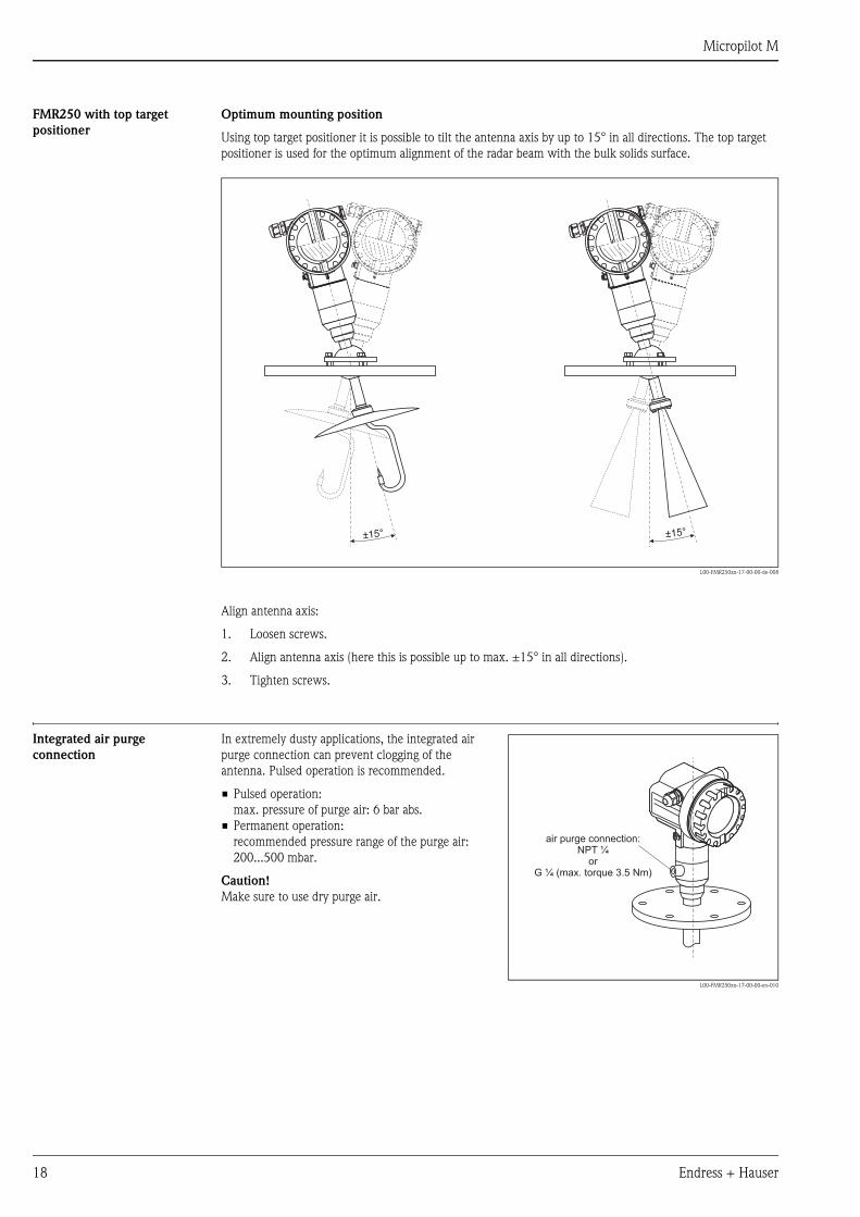
Optimum mounting position
Using top target positioner it is possible to tilt the antenna axis by up to 15° in all directions. The top target
positioner is used for the optimum alignment of the radar beam with the bulk solids surface.
L00-FMR250xx-17-00-00-de-008
Align antenna axis:
1. Loosen screws.
2. Align antenna axis (here this is possible up to max. ±15° in all directions).
3. Tighten screws.
Integrated air purge
connection
±15° ±15°
In extremely dusty applications, the integrated air
purge connection can prevent clogging of the
antenna. Pulsed operation is recommended.
• Pulsed operation:
max. pressure of purge air: 6 bar abs.
• Permanent operation:
recommended pressure range of the purge air:
200...500 mbar.
Caution!
Make sure to use dry purge air.
L00-FMR250xx-17-00-00-en-010
air purge connection:NPT
orG (max. torque 3.5 Nm)
¼
¼
Micropilot M
Endress + Hauser 19
Operating conditions: Environment
Ambient temperature range Ambient temperature for the transmitter: -40 °C … +80 °C (-40 °F … +176 °F), -50 °C (-58 °F) on request.
The functionality of the LCD display may be limited for temperatures Ta<-20 °C and Ta>+60 °C.
A weather protection cover should be used for outdoor operation if the instrument is exposed to direct sunlight.
Storage temperature -40 °C … +80 °C (-40 °F … +176°F), -50 °C (-58 °F) on request.
Climate class DIN EN 60068-2-38 (test Z/AD)
Degree of protection • housing: IP 65, NEMA 4X (open housing and pulled out display: IP20, NEMA 1)
• antenna: IP 68 (NEMA 6P)
Vibration resistance DIN EN 60068-2-64 / IEC 68-2-64: 20…2000 Hz, 1 (m/s2)2/Hz
Cleaning of the antenna The antenna can get contaminated, depending on the application. The emission and reception of microwaves
can thus eventually be hindered. The degree of contamination leading to an error depends on the medium and
the reflectivity, mainly determined by the dielectric constant εr. If the medium tends to cause contamination
and deposits, cleaning on a regular basis is recommended. Care has to be taken not to damage the antenna in
the process of a mechanical or hose-down cleaning (eventually air purge connection). The material
compatibility has to be considered if cleaning agents are used!
The maximum permitted temperature at the flange should not be exceeded.
Electromagnetic compatibility • Interference Emission to EN 61326, Electrical Equipment Class B
• Interference Immunity to EN 61326, Annex A (Industrial) and NAMUR Recommendation NE 21 (EMC)
• A standard installation cable is sufficient if only the analogue signal is used. Use a screened cable when
working with a superimposed communications signal (HART).
Operating conditions: Process
Process temperature range /
Process pressure limits
Optional top target positioner: ±15°, seal: FMK Viton GLT
Dielectric constant • in free space: εr ≥ 1.6 (for horizontal, even product surfaces: εr ≥ 1.4)
Type of antenna Seal Temperature Pressure Wetted parts
FMR250 E Standard FKM Viton GLT -40 °C ... +200 °C -1 ... 16 bar 1)
1) E+H UNI flange: -1...1 bar (...14.5 psi)
PEEK, seal,
316L/1.4404/1.4435
↑
Ordering information see Page 29
Micropilot M
20 Endress + Hauser
Mechanical construction
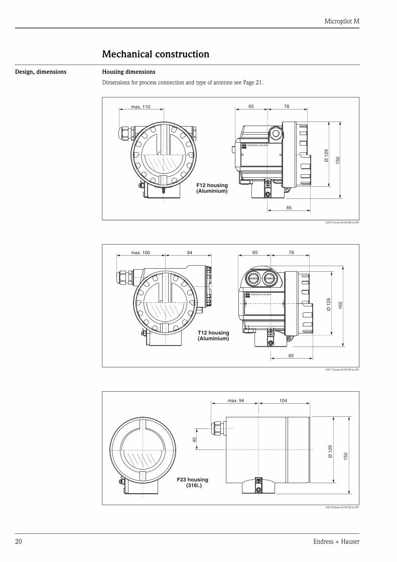
Design, dimensions Housing dimensions
Dimensions for process connection and type of antenne see Page 21.
L00-F12xxxx-06-00-00-en-001
L00-T12xxxx-06-00-00-en-001
L00-F23xxxx-06-00-00-en-001
ENDRESS+HAUSER
65 78max. 110
85
150
Ø 1
29
(Aluminium)F12 housing
ENDRESS+HAUSER
78
85
65
162
max. 100 94
Ø 1
29
(Aluminium)T12 housing
max. 94 104
Ø 1
29
150
40
(316L)F23 housing
Micropilot M
Endress + Hauser 21
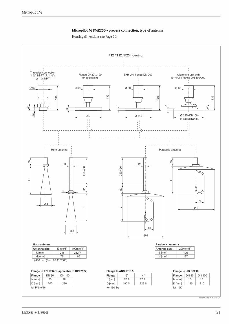
Micropilot M FMR250 - process connection, type of antenna
Housing dimensions see Page 20.
L00-FMR250xx-06-00-00-en-005
L
L L
L
50
50
13
5
40
13
5
13
5
13
5
50
50
Ø d
Ø d
40
27 27
Ø d
75
75
Ø d
25
0/4
50
25
0/4
50
75
211
80mm/3” 200mm/8”
95 197
282 1) 195
100mm/4”
b [mm] b [mm]b [mm]
DN 80 DN 803”
20 1823.9
200 185190.5
L [mm] L [mm]
d [mm] d [mm]
D [mm] D [mm]D [mm]220 210228.6
20 1823.9
DN 100 DN 1004”
Ø D Ø 340 Ø 225 (DN100)
340 (DN200)Ø
43
b
8 8
23
Ø 60Ø 60Ø 60Ø 60
Parabolic antennaHorn antenna
for 10K
Flange
Flange to JIS B2210
for 150 lbs
Flange
Flange to ANSI B16.5
for PN10/16
1) 430 mm (from 28.11.2005)
Antenna size Antenna size
Horn antenna Parabolic antenna
Flange
Flange to EN 1092-1 (agreeable to DIN 2527)
F12 / T12 / F23 housing
Threaded connectionBSPT (R 1 ½”)
or 1 ½ NPT1 ½” Flange DN80…100
or equivalentE+H UNI flange DN 200 Alignment unit with
E+H UNI flange DN 100/200

Micropilot M
22 Endress + Hauser
E+H UNI flange Installation hints
The number of bolts has sometimes been reduced. The bolt-holes have been enlarged for adaption of
dimensions, therefore, the flange needs to be properly aligned to the counterflange before the bolts are
tightened.
L00-FMR250xx-06-00-00-en-006
Top target positioner with E+H UNI flange
L00-FMR250xx-06-00-00-en-007
175
4x90°
4x90°
225
Ø 19
Ø 23
A
A
A
A
A-A
8
340
4x90°
6x60
°
Ø 26
Ø 26
E+H UNI flange DN100compatible with:- DN100 PN10/16,- ANSI 4" 150 lbs,- JIS 10K 100A
E+H UNI flange DN200compatible with:- DN200 PN10/16,- ANSI 8" 150 lbs,- JIS 10K 200A
material: 316L
M80x1.5
185.5
294.5
A
A-A
A
±15°
8
40
Ø 85
E+H UNI flangeDN100/DN200
clamping screw3 x M8 shifty at 120°
Viton seal
Micropilot M
Endress + Hauser 23
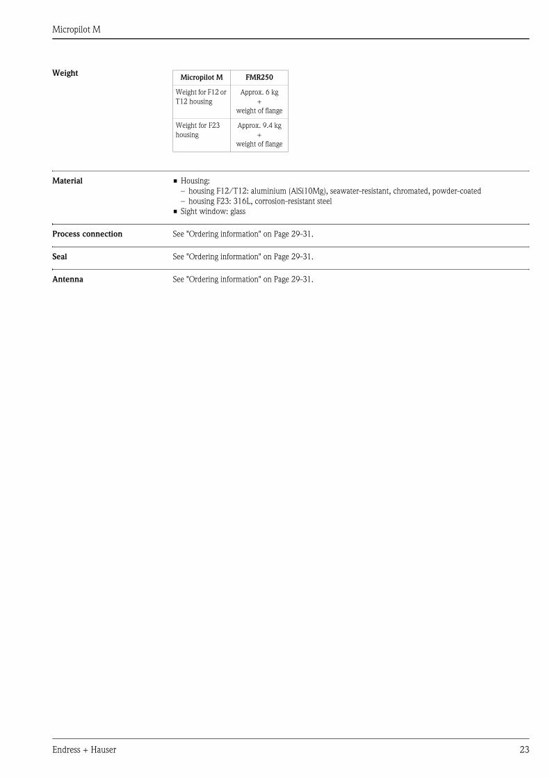
Weight
Material • Housing:
– housing F12/T12: aluminium (AlSi10Mg), seawater-resistant, chromated, powder-coated
– housing F23: 316L, corrosion-resistant steel
• Sight window: glass
Process connection See "Ordering information" on Page 29-31.
Seal See "Ordering information" on Page 29-31.
Antenna See "Ordering information" on Page 29-31.
Micropilot M FMR250
Weight for F12 or
T12 housing
Approx. 6 kg
+
weight of flange
Weight for F23
housing
Approx. 9.4 kg
+
weight of flange
Micropilot M
24 Endress + Hauser
Human interface
Operation concept The display of the process value and the configuration of the Micropilot occur locally by means of a large 4-line
alphanumeric display with plain text information. The guided menu system with integrated help texts ensures
a quick and safe commissioning.
To access the display the cover of the electronic compartment may be removed even in hazardous area (IS and
XP).
Remote commissioning, including documentation of the measuring point and in-depth analysis functions, is
supported via the ToF Tool, the graphical operating software for E+H time-of-flight systems.
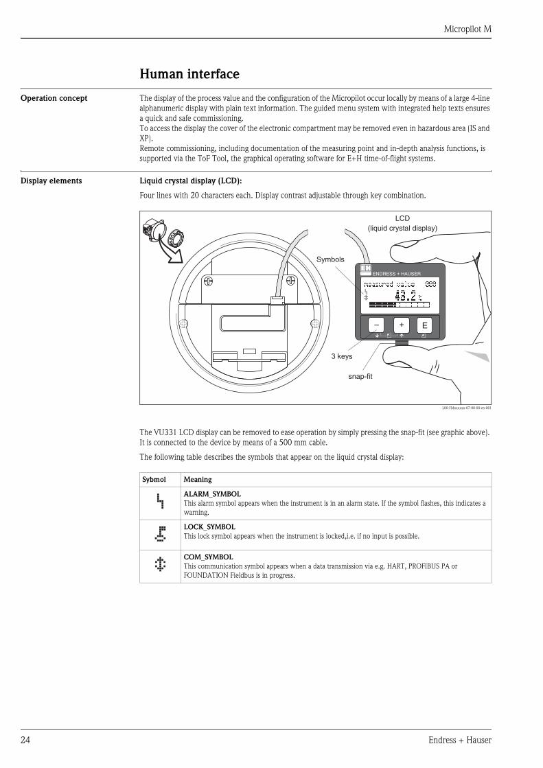
Display elements Liquid crystal display (LCD):
Four lines with 20 characters each. Display contrast adjustable through key combination.
L00-FMxxxxxx-07-00-00-en-001
The VU331 LCD display can be removed to ease operation by simply pressing the snap-fit (see graphic above).
It is connected to the device by means of a 500 mm cable.
The following table describes the symbols that appear on the liquid crystal display:
ENDRESS + HAUSER
E+–
ENDRESS+HAUSER
MICROPILOT II
ENDRESS+HAUSER
MICROPILOT II
IP 65IP 65
Order Code:Ser.-No.:
Order Code:Ser.-No.:
MessbereichMeasuring range
MessbereichMeasuring rangeU 16...36 V DC
4...20 mA
U 16...36 V DC
4...20 mA
max. 20 m
max. 20 m
Made
inG
erm
any
Maulb
urg
Made
inG
erm
any
Maulb
urg
T>70°C :
A
t >85°C
T>70°C :
A
t >85°C
LCD(liquid crystal display)
Symbols
3 keys
snap-fit
Sybmol Meaning
ALARM_SYMBOL
This alarm symbol appears when the instrument is in an alarm state. If the symbol flashes, this indicates a
warning.
LOCK_SYMBOL
This lock symbol appears when the instrument is locked,i.e. if no input is possible.
COM_SYMBOL
This communication symbol appears when a data transmission via e.g. HART, PROFIBUS PA or
FOUNDATION Fieldbus is in progress.
Micropilot M
Endress + Hauser 25
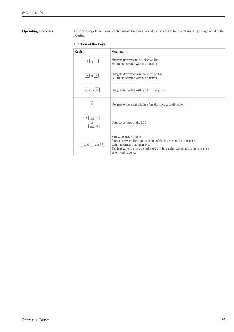
Operating elements The operating elements are located inside the housing and are accessible for operation by opening the lid of the
housing.
Function of the keys
Key(s) Meaning
O or V Navigate upwards in the selection list
Edit numeric value within a function
S or W Navigate downwards in the selection list
Edit numeric value within a function
X or Z Navigate to the left within a function group
F Navigate to the right within a function group, confirmation.
O and For
S and FContrast settings of the LCD
O and S and F
Hardware lock / unlock
After a hardware lock, an operation of the instrument via display or
communication is not possible!
The hardware can only be unlocked via the display. An unlock parameter must
be entered to do so.
Micropilot M
26 Endress + Hauser
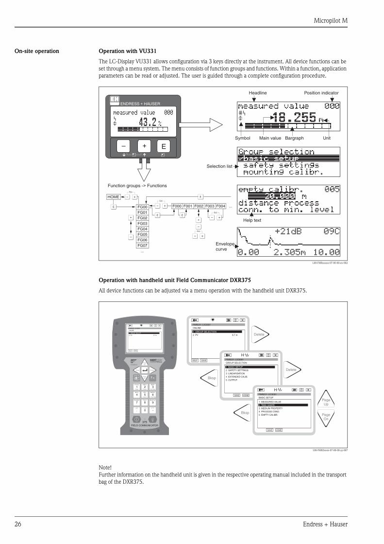
On-site operation Operation with VU331
The LC-Display VU331 allows configuration via 3 keys directly at the instrument. All device functions can be
set through a menu system. The menu consists of function groups and functions. Within a function, application
parameters can be read or adjusted. The user is guided through a complete configuration procedure.
L00-FMRxxxxx-07-00-00-en-002
Operation with handheld unit Field Communicator DXR375
All device functions can be adjusted via a menu operation with the handheld unit DXR375.
L00-FMR2xxxx-07-00-00-yy-007
Note!
Further information on the handheld unit is given in the respective operating manual included in the transport
bag of the DXR375.
XX
X
XS
S
OO FF
F
F
HOME
FG00 F000 F001 F002 F003 F004 ...
FG01FG02FG03FG04FG05FG06FG07
...
ENDRESS + HAUSER
E+–
Headline Position indicator
Main value UnitSymbol
Selection list
Function groups -> Functions
Help text
Envelopecurve
Bargraph
1# % &
Copy
G H I
P Q R S
, ( ) ‘
A B C
Paste
PageOn
PageUp
DeleteBksp
Insert
J K L
T U V
_ < >
D E F
Hot Key
+ Hot Key
M N O
W X Y Z
+ * /
4
7
.
2
5
8
0
375FIELD COMMUNICATOR
3
6
9
-
9 6
FMR231: LIC0001ONLINE
1 GROUP SELECT2 PV 8.7 m
HELP SAVE
dsdmdmdf das.asdas faasas la.
PageOn
PageUp
Bksp
Delete
Delete
FMR231: LIC0001ONLINE
1 GROUP SELECTION2 PV 8.7 m
HELP SAVE
dsdmdmdf das.asdas faasas la.
FMR231: LIC0001GROUP SELECTION
HOMESAVE
dsdmdmdf das.asdas faasas la.H
FMR231: LIC0001
HOMESAVE
dsdmdmdf das.asdas faasas la.H
Bksp
1 BASIC SETUP2 SAFETY SETTINGS
BASIC SETUP
1 MEASURED VALUE
4 PROCESS COND.
5 EMPTY CALIBR.
3 MEDIUM PROPERTY
4 EXTENDED CALIB.
5 OUTPUT
3 LINEARISATION
2 TANK SHAPE
Micropilot M
Endress + Hauser 27
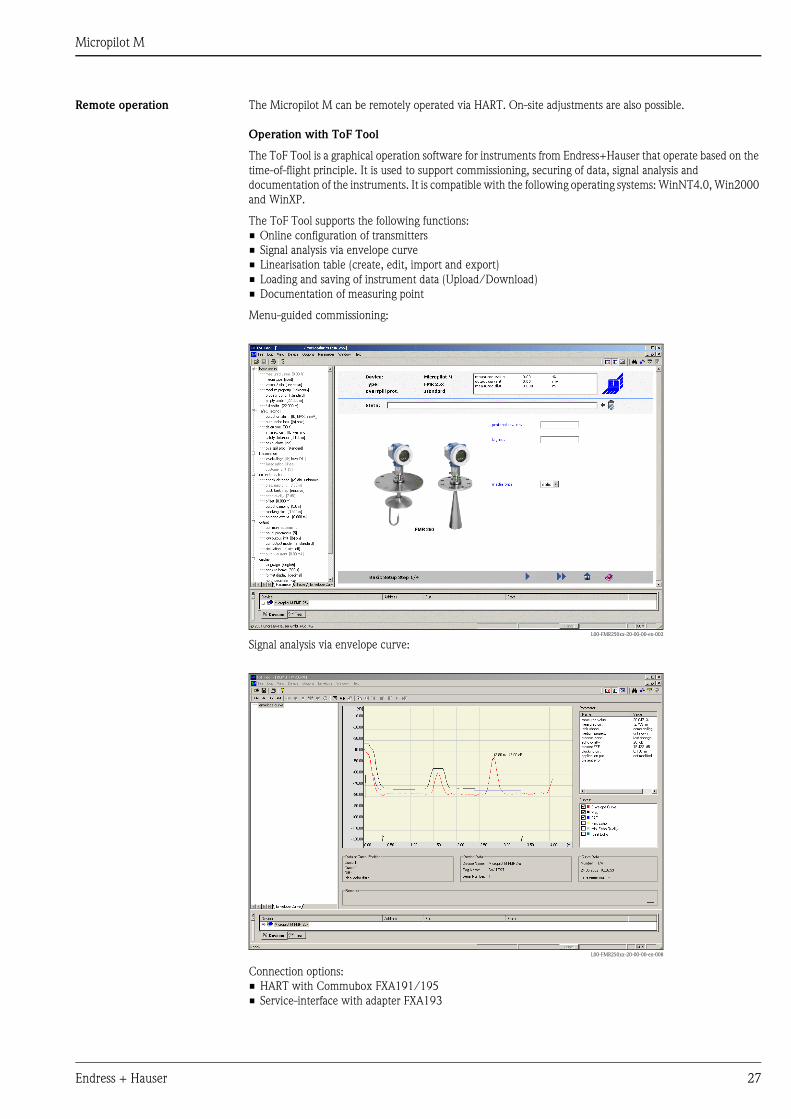
Remote operation The Micropilot M can be remotely operated via HART. On-site adjustments are also possible.
Operation with ToF Tool
The ToF Tool is a graphical operation software for instruments from Endress+Hauser that operate based on the
time-of-flight principle. It is used to support commissioning, securing of data, signal analysis and
documentation of the instruments. It is compatible with the following operating systems: WinNT4.0, Win2000
and WinXP.
The ToF Tool supports the following functions:
• Online configuration of transmitters
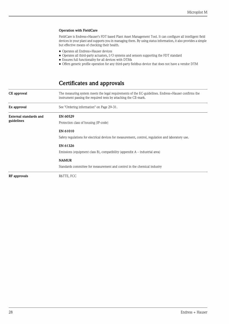
• Signal analysis via envelope curve
• Linearisation table (create, edit, import and export)
• Loading and saving of instrument data (Upload/Download)
• Documentation of measuring point
Menu-guided commissioning:
Signal analysis via envelope curve:
Connection options:
• HART with Commubox FXA191/195
• Service-interface with adapter FXA193
L00-FMR250xx-20-00-00-en-002
L00-FMR250xx-20-00-00-en-008
Micropilot M
28 Endress + Hauser
Operation with FieldCare
FieldCare is Endress+Hauser's FDT based Plant Asset Management Tool. It can configure all intelligent field
devices in your plant and supports you in managing them. By using status information, it also provides a simple
but effective means of checking their health.
• Operates all Endress+Hauser devices
• Operates all third-party actuators, I/O systems and sensors supporting the FDT standard
• Ensures full functionality for all devices with DTMs
• Offers generic profile operation for any third-party fieldbus device that does not have a vendor DTM
Certificates and approvals
CE approval The measuring system meets the legal requirements of the EC-guidelines. Endress+Hauser confirms the
instrument passing the required tests by attaching the CE-mark.
Ex approval See "Ordering information" on Page 29-31.
External standards and
guidelines
EN 60529
Protection class of housing (IP-code)
EN 61010
Safety regulations for electrical devices for measurement, control, regulation and laboratory use.
EN 61326
Emissions (equipment class B), compatibility (appendix A – industrial area)
NAMUR
Standards committee for measurement and control in the chemical industry
RF approvals R&TTE, FCC
Micropilot M
Endress + Hauser 29
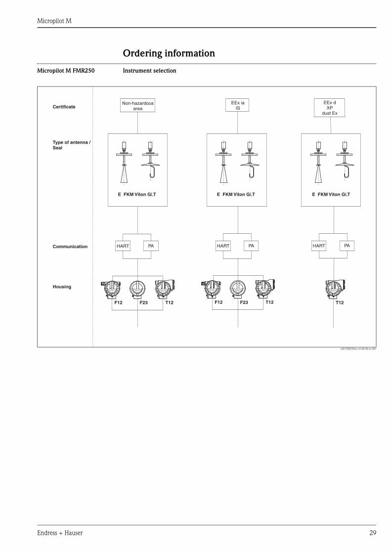
Ordering information
Micropilot M FMR250 Instrument selection
L00-FMR250xx-16-00-00-en-001
E FKM Viton GLT E FKM Viton GLT E FKM Viton GLT
T12 T12 T12F12 F12F23 F23
EEx iaIS
PA PA PAHART HART HART
Non-hazardousareaCertificate
Type of antenna /Seal
Communication
Housing
EEx dXP
dust Ex
Micropilot M
30 Endress + Hauser
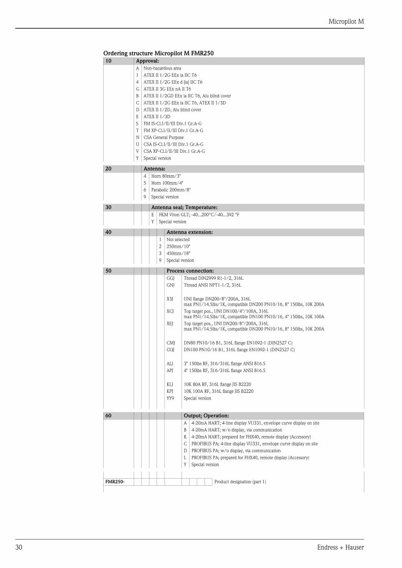
Ordering structure Micropilot M FMR250
10 Approval:
A Non-hazardous area
1 ATEX II 1/2G EEx ia IIC T6
4 ATEX II 1/2G EEx d [ia] IIC T6
G ATEX II 3G EEx nA II T6
B ATEX II 1/2GD EEx ia IIC T6, Alu blind cover
C ATEX II 1/2G EEx ia IIC T6, ATEX II 1/3D
D ATEX II 1/2D, Alu blind cover
E ATEX II 1/3D
S FM IS-Cl.I/II/III Div.1 Gr.A-G
T FM XP-Cl.I/II/III Div.1 Gr.A-G
N CSA General Purpose
U CSA IS-Cl.I/II/III Div.1 Gr.A-G
V CSA XP-Cl.I/II/III Div.1 Gr.A-G
Y Special version
20 Antenna:
4 Horn 80mm/3"
5 Horn 100mm/4"
6 Parabolic 200mm/8"
9 Special version
30 Antenna seal; Temperature:
E FKM Viton GLT; -40...200°C/-40...392 °F
Y Special version
40 Antenna extension:
1 Not selected
2 250mm/10"
3 450mm/18"
9 Special version
50 Process connection:
GGJ Thread DIN2999 R1-1/2, 316L
GNJ Thread ANSI NPT1-1/2, 316L
X3J UNI flange DN200/8"/200A, 316L
max PN1/14.5lbs/1K, compatible DN200 PN10/16, 8" 150lbs, 10K 200A
XCJ Top target pos., UNI DN100/4"/100A, 316L
max PN1/14.5lbs/1K, compatible DN100 PN10/16, 4" 150lbs, 10K 100A
XEJ Top target pos., UNI DN200/8"/200A, 316L
max PN1/14.5lbs/1K, compatible DN200 PN10/16, 8" 150lbs, 10K 200A
CMJ DN80 PN10/16 B1, 316L flange EN1092-1 (DIN2527 C)
CQJ DN100 PN10/16 B1, 316L flange EN1092-1 (DIN2527 C)
ALJ 3" 150lbs RF, 316/316L flange ANSI B16.5
APJ 4" 150lbs RF, 316/316L flange ANSI B16.5
KLJ 10K 80A RF, 316L flange JIS B2220
KPJ 10K 100A RF, 316L flange JIS B2220
YY9 Special version
60 Output; Operation:
A 4-20mA HART; 4-line display VU331, envelope curve display on site
B 4-20mA HART; w/o display, via communication
K 4-20mA HART; prepared for FHX40, remote display (Accessory)
C PROFIBUS PA; 4-line display VU331, envelope curve display on site
D PROFIBUS PA; w/o display, via communication
L PROFIBUS PA; prepared for FHX40, remote display (Accessory)
Y Special version
FMR250- Product designation (part 1)
Micropilot M
Endress + Hauser 31
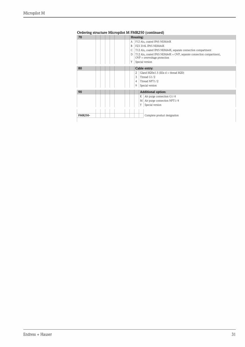
Ordering structure Micropilot M FMR250 (continued)
70 Housing:
A F12 Alu, coated IP65 NEMA4X
B F23 316L IP65 NEMA4X
C T12 Alu, coated IP65 NEMA4X, separate connection compartment
D T12 Alu, coated IP65 NEMA4X + OVP, separate connection compartment,
OVP = overvoltage protection
Y Special version
80 Cable entry:
2 Gland M20x1.5 (EEx d > thread M20)
3 Thread G1/2
4 Thread NPT1/2
9 Special version
90 Additional option:
K Air purge connection G1/4
M Air purge connection NPT1/4
Y Special version
FMR250- Complete product designation
Micropilot M
32 Endress + Hauser
Accessories
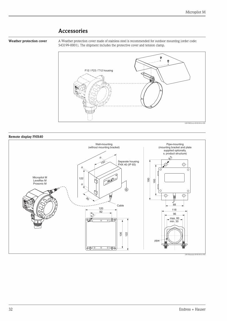
Weather protection cover A Weather protection cover made of stainless steel is recommended for outdoor mounting (order code:
543199-0001). The shipment includes the protective cover and tension clamp.
L00-FMR2xxxx-00-00-06-en-001
Remote display FHX40
L00-FMxxxxxx-00-00-06-en-003
ENDRESS+HAUSER
MICROPILOT II
ENDRESS+HAUSER
MICROPILOT II
IP 65
Order Code:Ser.-No.:
Order Code:Ser.-No.:
MessbereichMeasuring range
MessbereichMeasuring rangeU 16...36 V DC
4...20 mA
U 16...36 V DC4...20 mA
max. 20 m
max. 20 m
Made in
Germ
any
Maulb
urg
Made in
Germ
any
Maulb
urg
T>70°C :
A
t >85°C
T>70°C :
A
t >85°C
F12 / F23 / T12 housing
ENDRESS+HAUSER
ENDRESS+HAUSER
IP 65IP 65
Order Code:Ser.-No.:
Order Code:Ser.-No.:
MessbereichMeasuring range
MessbereichMeasuring rangeU 16...36 V DC
4...20 mA
U 16...36 V DC4...20 mA
max. 20 m
max. 20 m
Made in
Germ
any
M
aulb
urg
Made in
Germ
any
M
aulb
urg
T>70°C :
A
t >85°C
T>70°C :
A
t >85°C 82
6,3
106
122
120
max. 80min. 30
96
88
160
8,5
118
180Micropilot M
Levelflex MProsonic M
Separate housingFHX 40 (IP 65)
Cable
122
150
80
Wall-mounting(without mounting bracket)
Pipe-mounting(mounting bracket and plate
supplied optionally,s. product structure)
pipe
Micropilot M
Endress + Hauser 33
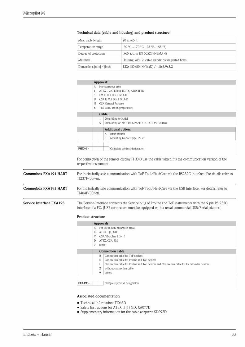
Technical data (cable and housing) and product structure:
For connection of the remote display FHX40 use the cable which fits the communication version of the
respective instrument.
Commubox FXA191 HART For intrinsically safe communication with ToF Tool/FieldCare via the RS232C interface. For details refer to
TI237F/00/en.
Commubox FXA195 HART For intrinsically safe communication with ToF Tool/FieldCare via the USB interface. For details refer to
TI404F/00/en.
Service Interface FXA193 The Service-Interface connects the Service plug of Proline and ToF instruments with the 9 pin RS 232C
interface of a PC. (USB connectors must be equipped with a usual commercial USB/Serial adapter.)
Product structure
Associated documentation
• Technical Information: TI063D
• Safety Instructions for ATEX II (1) GD: XA077D
• Supplementary information for the cable adapters: SD092D
Max. cable length 20 m (65 ft)
Temperature range -30 °C...+70 °C (-22 °F...158 °F)
Degree of protection IP65 acc. to EN 60529 (NEMA 4)
Materials Housing: AlSi12; cable glands: nickle plated brass
Dimensions [mm] / [inch] 122x150x80 (HxWxD) / 4.8x5.9x3.2
Approval:
A Nn-hazardous area
1 ATEX II 2 G EEx ia IIC T6, ATEX II 3D
S FM IS Cl.I Div.1 Gr.A-D
U CSA IS Cl.I Div.1 Gr.A-D
N CSA General Purpose
K TIIS ia IIC T6 (in preparation)
Cable:
1 20m/65ft; for HART
5 20m/65ft; for PROFIBUS PA/FOUNDATION Fieldbus
Additional option:
A Basic version
B Mounting bracket, pipe 1"/ 2"
FHX40 - Complete product designation
Approvals
A For use in non-hazardous areas
B ATEX II (1) GD
C CSA/FM Class I Div. 1
D ATEX, CSA, FM
9 other
Connection cable
B Connection cable for ToF devices
E Connection cable for Proline and ToF devices
H Connection cable for Proline and ToF devices and Connection cable for Ex two-wire devices
X without connection cable
9 others
FXA193- Complete product designation
Micropilot M
34 Endress + Hauser
DocumentationThis supplementary documentation can be found on our product pages on "www.endress.com".
System Information System Information for Micropilot, SI019F/00/en.
Technical Information Fieldgate FXA320, FXA520
Technical Information for Fieldgate FXA320/520, TI369F/00/en.
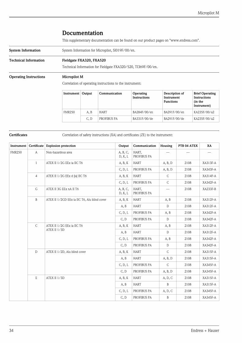
Operating Instructions Micropilot M
Correlation of operating instructions to the instrument:
Certificates Correlation of safety instructions (XA) and certificates (ZE) to the instrument:
Instrument Output Communication Operating
Instructions
Description of
Instrument
Functions
Brief Operating
Instructions
(in the
Instrument)
FMR250 A, B HART BA284F/00/en BA291F/00/en KA235F/00/a2
C, D PROFIBUS PA BA331F/00/de BA291F/00/de KA235F/00/a2
Instrument Certificate Explosion protection Output Communication Housing PTB 04 ATEX XA
FMR250 A Non-hazardous area A, B, C,
D, K, L
HART,
PROFIBUS PA
— — —
1 ATEX II 1/2G EEx ia IIC T6 A, B, K HART A, B, D 2108 XA313F-A
C, D, L PROFIBUS PA A, B, D 2108 XA343F-A
4 ATEX II 1/2G EEx d [ia] IIC T6 A, B, K HART C 2108 XA314F-A
C, D, L PROFIBUS PA C 2108 XA342F-A
G ATEX II 3G EEx nA II T6 A, B, C,
D, K, L
HART,
PROFIBUS PA
— 2108 XA233F-B
B ATEX II 1/2GD EEx ia IIC T6, Alu blind cover A, B, K HART A, B 2108 XA312F-A
A, B HART D 2108 XA312F-A
C, D, L PROFIBUS PA A, B 2108 XA342F-A
C, D PROFIBUS PA D 2108 XA342F-A
C ATEX II 1/2G EEx ia IIC T6
ATEX II 1/3D
A, B, K HART A, B 2108 XA312F-A
A, B HART D 2108 XA312F-A
C, D, L PROFIBUS PA A, B 2108 XA342F-A
C, D PROFIBUS PA D 2108 XA342F-A
D ATEX II 1/2D, Alu blind cover A, B, K HART C 2108 XA315F-A
A, B HART A, B, D 2108 XA315F-A
C, D, L PROFIBUS PA C 2108 XA345F-A
C, D PROFIBUS PA A, B, D 2108 XA345F-A
E ATEX II 1/3D A, B, K HART A, D, C 2108 XA315F-A
A, B HART B 2108 XA315F-A
C, D, L PROFIBUS PA A, D, C 2108 XA345F-A
C, D PROFIBUS PA B 2108 XA345F-A
Micropilot M
Endress + Hauser 35
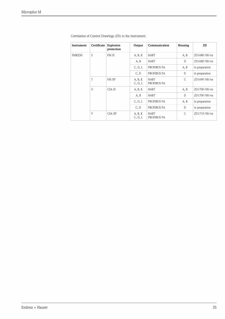
Correlation of Control Drawings (ZD) to the instrument:
Instrument Certificate Explosion
protection
Output Communication Housing ZD
FMR250 S FM IS A, B, K HART A, B ZD168F/00/en
A, B HART D ZD168F/00/en
C, D, L PROFIBUS PA A, B in preparation
C, D PROFIBUS PA D in preparation
T FM XP A, B, K
C, D, L
HART
PROFIBUS PA
C ZD169F/00/en
U CSA IS A, B, K HART A, B ZD170F/00/en
A, B HART D ZD170F/00/en
C, D, L PROFIBUS PA A, B in preparation
C, D PROFIBUS PA D in preparation
V CSA XP A, B, K
C, D, L
HART
PROFIBUS PA
C ZD171F/00/en
Micropilot M
This product may be protected by at least one of the following patents.
Further patents are pending.
• US 5,387,918 i EP 0 535 196
• US 5,689,265 i EP 0 626 063
• US 5,659,321
• US 5,614,911 i EP 0 670 048
• US 5,594,449 i EP 0 676 037
• US 6,047,598
• US 5,880,698
• US 5,926,152
• US 5,969,666
• US 5,948,979
• US 6,054,946
• US 6,087,978
• US 6,014,100
International Head Quarter
Endress+Hauser
GmbH+Co. KG
Instruments International
Colmarer Str. 6
79576 Weil am Rhein
Deutschland
Tel. +49 76 21 9 75 02
Fax +49 76 21 9 75 34 5
www.endress.com
TI390F/00/en/12.05
FM+SGML 6.0 ProMoDo
Recommended