Embed Size (px)
Citation preview

Level measurement in bulk solids
Application
Continuous, non-contact level measurement in powdery to granular bulk solids
Features FMR56:• Attractively-priced basic device for standard process conditions (e.g. bulk cargo
silos, bulk storage tanks)• PP-cladded horn antenna• Maximum measuring range: 30 m (98 ft)• Mounting bracket or variable flange seal for alignment• Temperature range: –40 to +80 °C (–40 to 176 °F)• Pressure range: –1 to +3 bar (–14.5 to +43.5 psi)• Accuracy: ±3 mmFeatures FMR57:• For highly demanding solid applications (e.g. high silos, bunkers, stockpiles)• Horn or parabolic antenna• Air purge connection integrated• Maximum measuring range: 70 m (230 ft)• Temperature range: –40 to +400 °C (–40 to 752 °F)• Pressure range: –1 to +16 bar (–14.5 to +232 psi)• Accuracy: ±3 mm
Your benefits
• Reliable even under changing product and process conditions• Integrated data memory (HistoROM) for high availability• Intuitive operating menu in national languages for easy commissioning• Exact diagnostic and process information• International approvals for use in hazardous areas• 5-point linearity protocol• SIL2 according to IEC 61508, SIL3 in case of homogeneous or heterogeneous
redundancy• System integration via HART/PROFIBUS PA (Profile 3.02)/FOUNDATION Fieldbus
Products Solutions Services
Technical InformationMicropilot FMR56, FMR57Level radar
TI01042F/00/EN/03.1371224360
Micropilot FMR56, FMR57
2 Endress+Hauser
Table of contents
Important document information . . . . . . . . . . . . . . . 3Document conventions . . . . . . . . . . . . . . . . . . . . . . . . . . 3
Function and system design . . . . . . . . . . . . . . . . . . . 5Measuring principle . . . . . . . . . . . . . . . . . . . . . . . . . . . . 5
Input . . . . . . . . . . . . . . . . . . . . . . . . . . . . . . . . . . . . . 7Measured variable . . . . . . . . . . . . . . . . . . . . . . . . . . . . . 7Measuring range . . . . . . . . . . . . . . . . . . . . . . . . . . . . . . 7Operating frequency . . . . . . . . . . . . . . . . . . . . . . . . . . . 8Transmitting power . . . . . . . . . . . . . . . . . . . . . . . . . . . . 8
Output . . . . . . . . . . . . . . . . . . . . . . . . . . . . . . . . . . . 9Output signal . . . . . . . . . . . . . . . . . . . . . . . . . . . . . . . . 9Signal on alarm . . . . . . . . . . . . . . . . . . . . . . . . . . . . . . 10Linearization . . . . . . . . . . . . . . . . . . . . . . . . . . . . . . . 10Galvanic isolation . . . . . . . . . . . . . . . . . . . . . . . . . . . . 10Protocol-specific data . . . . . . . . . . . . . . . . . . . . . . . . . . 10
Power supply . . . . . . . . . . . . . . . . . . . . . . . . . . . . . 15Terminal assignment . . . . . . . . . . . . . . . . . . . . . . . . . . 15Device plug connectors . . . . . . . . . . . . . . . . . . . . . . . . . 22Supply voltage . . . . . . . . . . . . . . . . . . . . . . . . . . . . . . 23Power consumption . . . . . . . . . . . . . . . . . . . . . . . . . . . 25Current consumption . . . . . . . . . . . . . . . . . . . . . . . . . . 25Power supply failure . . . . . . . . . . . . . . . . . . . . . . . . . . 26Potential equalization . . . . . . . . . . . . . . . . . . . . . . . . . 26Terminals . . . . . . . . . . . . . . . . . . . . . . . . . . . . . . . . . 26Cable entries . . . . . . . . . . . . . . . . . . . . . . . . . . . . . . . 26Cable specification . . . . . . . . . . . . . . . . . . . . . . . . . . . . 26Overvoltage protection . . . . . . . . . . . . . . . . . . . . . . . . . 27
Performance characteristics . . . . . . . . . . . . . . . . . . 28Reference operating conditions . . . . . . . . . . . . . . . . . . . 28Maximum measured error . . . . . . . . . . . . . . . . . . . . . . . 28Measured value resolution . . . . . . . . . . . . . . . . . . . . . . 28Reaction time . . . . . . . . . . . . . . . . . . . . . . . . . . . . . . . 29Influence of ambient temperature . . . . . . . . . . . . . . . . . 29
Installation . . . . . . . . . . . . . . . . . . . . . . . . . . . . . . . 30Installation conditions . . . . . . . . . . . . . . . . . . . . . . . . . 30Measuring conditions . . . . . . . . . . . . . . . . . . . . . . . . . . 37Installation in vessel (free space) . . . . . . . . . . . . . . . . . . 38Vessels with heat insulation . . . . . . . . . . . . . . . . . . . . . 47
Environment . . . . . . . . . . . . . . . . . . . . . . . . . . . . . . 48Ambient temperature range . . . . . . . . . . . . . . . . . . . . . 48Ambient temperature limits . . . . . . . . . . . . . . . . . . . . . 48Storage temperature . . . . . . . . . . . . . . . . . . . . . . . . . . 52Climate class . . . . . . . . . . . . . . . . . . . . . . . . . . . . . . . 52Altitude according to IEC61010-1 Ed.3 . . . . . . . . . . . . . . 52Degree of protection . . . . . . . . . . . . . . . . . . . . . . . . . . 52Vibration resistance . . . . . . . . . . . . . . . . . . . . . . . . . . . 52Cleaning the antenna . . . . . . . . . . . . . . . . . . . . . . . . . . 52Electromagnetic compatibility (EMC) . . . . . . . . . . . . . . . 53
Process . . . . . . . . . . . . . . . . . . . . . . . . . . . . . . . . . . 54Process temperature range . . . . . . . . . . . . . . . . . . . . . . 54Process pressure range . . . . . . . . . . . . . . . . . . . . . . . . . 54Dielectric constant . . . . . . . . . . . . . . . . . . . . . . . . . . . . 54
Mechanical construction . . . . . . . . . . . . . . . . . . . . 55Dimensions . . . . . . . . . . . . . . . . . . . . . . . . . . . . . . . . 55Weight . . . . . . . . . . . . . . . . . . . . . . . . . . . . . . . . . . . 62Materials . . . . . . . . . . . . . . . . . . . . . . . . . . . . . . . . . . 63
Operability . . . . . . . . . . . . . . . . . . . . . . . . . . . . . . . 68Operating concept . . . . . . . . . . . . . . . . . . . . . . . . . . . . 68Local operation . . . . . . . . . . . . . . . . . . . . . . . . . . . . . . 68Operation with remote display and operating moduleFHX50 . . . . . . . . . . . . . . . . . . . . . . . . . . . . . . . . . . . 69Remote operation . . . . . . . . . . . . . . . . . . . . . . . . . . . . 69System integration via Fieldgate . . . . . . . . . . . . . . . . . . . 73
Certificates and approvals . . . . . . . . . . . . . . . . . . . 74CE mark . . . . . . . . . . . . . . . . . . . . . . . . . . . . . . . . . . . 74C-Tick symbol . . . . . . . . . . . . . . . . . . . . . . . . . . . . . . . 74Ex approval . . . . . . . . . . . . . . . . . . . . . . . . . . . . . . . . 74Dual seal according to ANSI/ISA 12.27.01 . . . . . . . . . . . . 74Functional Safety . . . . . . . . . . . . . . . . . . . . . . . . . . . . 74WHG . . . . . . . . . . . . . . . . . . . . . . . . . . . . . . . . . . . . . 74AD2000 . . . . . . . . . . . . . . . . . . . . . . . . . . . . . . . . . . 74Pressure Equipment Directive . . . . . . . . . . . . . . . . . . . . 74Marine certificate (in preparation) . . . . . . . . . . . . . . . . . 74Radio standard EN302729-1/2 . . . . . . . . . . . . . . . . . . . 74Radio standard EN302372-1/2 . . . . . . . . . . . . . . . . . . . 75FCC / Industry Canada . . . . . . . . . . . . . . . . . . . . . . . . . 75Japanes radio approval . . . . . . . . . . . . . . . . . . . . . . . . . 76CRN approval . . . . . . . . . . . . . . . . . . . . . . . . . . . . . . . 76Track record . . . . . . . . . . . . . . . . . . . . . . . . . . . . . . . . 76Other standards and guidelines . . . . . . . . . . . . . . . . . . . 76
Ordering information . . . . . . . . . . . . . . . . . . . . . . . 77Ordering information . . . . . . . . . . . . . . . . . . . . . . . . . . 775-point linearity protocol . . . . . . . . . . . . . . . . . . . . . . . 77Customized parametrization . . . . . . . . . . . . . . . . . . . . . 78
Accessories . . . . . . . . . . . . . . . . . . . . . . . . . . . . . . . 79Device-specific accessories . . . . . . . . . . . . . . . . . . . . . . 79Communication-specific accessories . . . . . . . . . . . . . . . . 82Service-specific accessories . . . . . . . . . . . . . . . . . . . . . . 83System components . . . . . . . . . . . . . . . . . . . . . . . . . . . 84
Documentation . . . . . . . . . . . . . . . . . . . . . . . . . . . . 85Standard documentation . . . . . . . . . . . . . . . . . . . . . . . . 85Supplementary documentation . . . . . . . . . . . . . . . . . . . 85Safety Instructions (XA) . . . . . . . . . . . . . . . . . . . . . . . . 85
Registered trademarks . . . . . . . . . . . . . . . . . . . . . . 87
Patents . . . . . . . . . . . . . . . . . . . . . . . . . . . . . . . . . . 87
Micropilot FMR56, FMR57
Endress+Hauser 3
Important document information
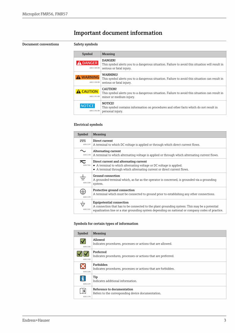
Document conventions Safety symbols
Symbol Meaning
DANGER
A0011189-EN
DANGER!This symbol alerts you to a dangerous situation. Failure to avoid this situation will result inserious or fatal injury.
WARNING
A0011190-EN
WARNING!This symbol alerts you to a dangerous situation. Failure to avoid this situation can result inserious or fatal injury.
CAUTION
A0011191-EN
CAUTION!This symbol alerts you to a dangerous situation. Failure to avoid this situation can result inminor or medium injury.
NOTICE
A0011192-EN
NOTICE!This symbol contains information on procedures and other facts which do not result inpersonal injury.
Electrical symbols
Symbol Meaning
A0011197
Direct currentA terminal to which DC voltage is applied or through which direct current flows.
A0011198
Alternating currentA terminal to which alternating voltage is applied or through which alternating current flows.
A0017381
Direct current and alternating current• A terminal to which alternating voltage or DC voltage is applied.• A terminal through which alternating current or direct current flows.
A0011200
Ground connectionA grounded terminal which, as far as the operator is concerned, is grounded via a groundingsystem.
A0011199
Protective ground connectionA terminal which must be connected to ground prior to establishing any other connections.
A0011201
Equipotential connectionA connection that has to be connected to the plant grounding system: This may be a potentialequalization line or a star grounding system depending on national or company codes of practice.
Symbols for certain types of information
Symbol Meaning
A0011182
AllowedIndicates procedures, processes or actions that are allowed.
A0011183
PreferredIndicates procedures, processes or actions that are preferred.
A0011184
ForbiddenIndicates procedures, processes or actions that are forbidden.
A0011193
TipIndicates additional information.
A0011194
Reference to documentationRefers to the corresponding device documentation.
Micropilot FMR56, FMR57
4 Endress+Hauser
Symbol Meaning
A0011195
Reference to pageRefers to the corresponding page number.
A0011196
Reference to graphicRefers to the corresponding graphic number and page number.
Symbols in graphics
Symbol Meaning
1, 2, 3 ... Item numbers
, …, Series of steps
A, B, C, ... Views
A-A, B-B, C-C, ... Sections
- A0011187
Hazardous areaIndicates a hazardous area.
. A0011188
Safe area (non-hazardous area)Indicates a non-hazardous location.
Symbols at the device
Symbol Meaning
Safety instructionsObserve the safety instructions contained in the associated Operating Instructions.
Temperature resistance of the connection cablesSpecifies the minimum value of the temperature resistance of the connection cables.
Micropilot FMR56, FMR57
Endress+Hauser 5
Function and system design
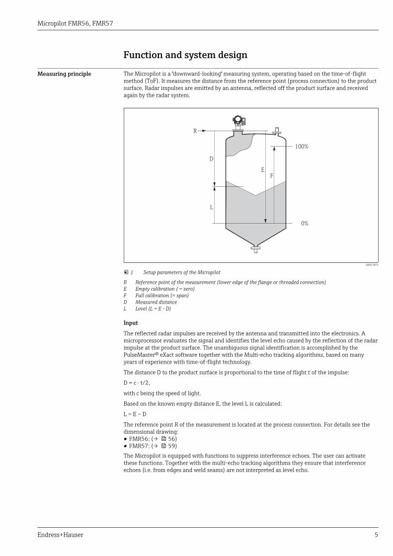
Measuring principle The Micropilot is a "downward-looking" measuring system, operating based on the time-of-flightmethod (ToF). It measures the distance from the reference point (process connection) to the productsurface. Radar impulses are emitted by an antenna, reflected off the product surface and receivedagain by the radar system.
F
L
D
E
100%
0%
R
A0017872
1 Setup parameters of the Micropilot
R Reference point of the measurement (lower edge of the flange or threaded connection)E Empty calibration ( = zero)F Full calibration (= span)D Measured distanceL Level (L = E - D)
Input
The reflected radar impulses are received by the antenna and transmitted into the electronics. Amicroprocessor evaluates the signal and identifies the level echo caused by the reflection of the radarimpulse at the product surface. The unambiguous signal identification is accomplished by thePulseMaster® eXact software together with the Multi-echo tracking algorithms, based on manyyears of experience with time-of-flight technology.
The distance D to the product surface is proportional to the time of flight t of the impulse:
D = c · t/2,
with c being the speed of light.
Based on the known empty distance E, the level L is calculated:
L = E – D
The reference point R of the measurement is located at the process connection. For details see thedimensional drawing:• FMR56: (→ 56)• FMR57: (→ 59)The Micropilot is equipped with functions to suppress interference echoes. The user can activatethese functions. Together with the multi-echo tracking algorithms they ensure that interferenceechoes (i.e. from edges and weld seams) are not interpreted as level echo.
Micropilot FMR56, FMR57
6 Endress+Hauser
Output
The Micropilot is commissioned by entering an empty distance "E" (=zero), a full distance "F" (=span)and application parameters. The application parameters are automatically adapt into the instrumentto the process conditions. For models with a current output, the factory adjustment for zero point "E"and span "F" is 4 mA and 20 mA. For digital outputs and the display module, the factory adjustmentfor zero point "E" and span "F" is 0 % and 100 %.
A linearization with max. 32 points, based on a table entered either manually or semi-automatically,can be activated locally or remotely. This function provides a measurement in engineering units anda linear output signal for spheres, horizontal cylindrical tanks and vessels with conical outlet.
Life cycle of the product
Engineering Procurement Installation Commissioning Operation Maintenance Retirement
A0013773-EN
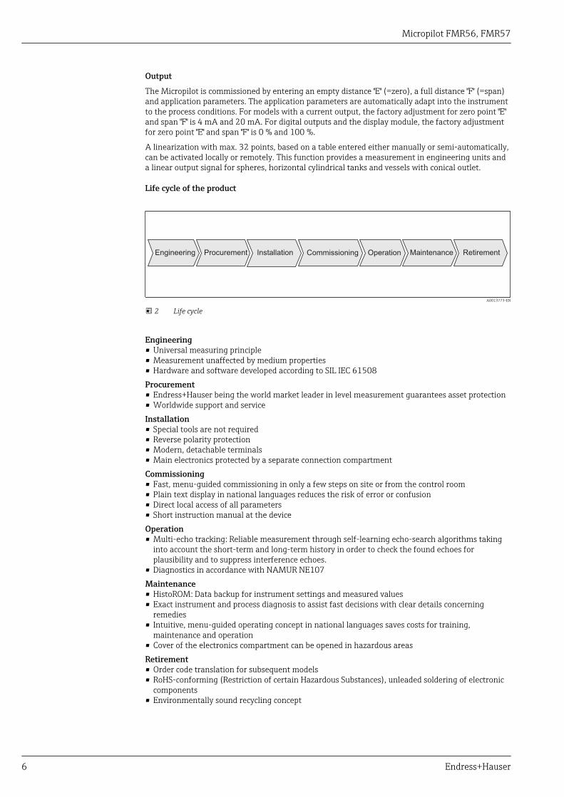
2 Life cycle
Engineering• Universal measuring principle• Measurement unaffected by medium properties• Hardware and software developed according to SIL IEC 61508Procurement• Endress+Hauser being the world market leader in level measurement guarantees asset protection• Worldwide support and serviceInstallation• Special tools are not required• Reverse polarity protection• Modern, detachable terminals• Main electronics protected by a separate connection compartmentCommissioning• Fast, menu-guided commissioning in only a few steps on site or from the control room• Plain text display in national languages reduces the risk of error or confusion• Direct local access of all parameters• Short instruction manual at the deviceOperation• Multi-echo tracking: Reliable measurement through self-learning echo-search algorithms taking
into account the short-term and long-term history in order to check the found echoes forplausibility and to suppress interference echoes.
• Diagnostics in accordance with NAMUR NE107Maintenance• HistoROM: Data backup for instrument settings and measured values• Exact instrument and process diagnosis to assist fast decisions with clear details concerning
remedies• Intuitive, menu-guided operating concept in national languages saves costs for training,
maintenance and operation• Cover of the electronics compartment can be opened in hazardous areasRetirement• Order code translation for subsequent models• RoHS-conforming (Restriction of certain Hazardous Substances), unleaded soldering of electronic
components• Environmentally sound recycling concept
Micropilot FMR56, FMR57
Endress+Hauser 7
Input
Measured variable The measured variable is the distance between the reference point and the product surface.
The level is calculated from this distance, taking into account the empty distance "E" entered by theuser.
If required, the level can be converted into other variables (volume, mass) by means of a linearization(up to 32 points).
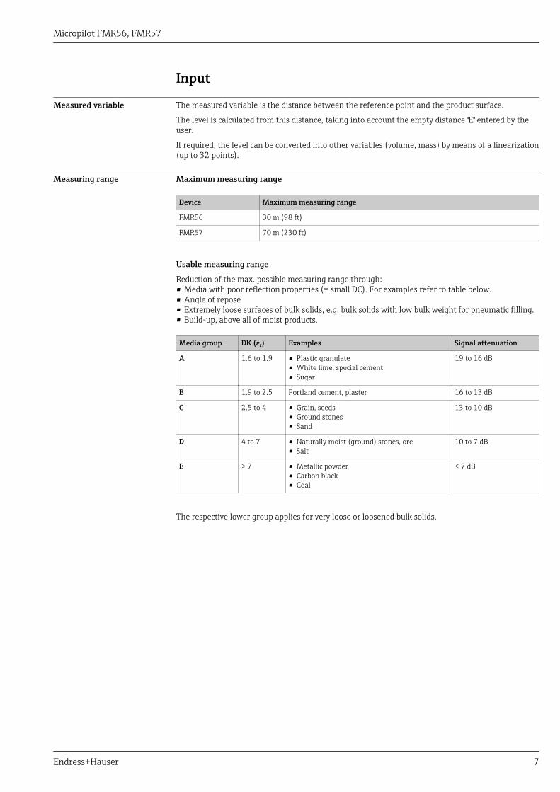
Measuring range Maximum measuring range
Device Maximum measuring range
FMR56 30 m (98 ft)
FMR57 70 m (230 ft)
Usable measuring range
Reduction of the max. possible measuring range through:• Media with poor reflection properties (= small DC). For examples refer to table below.• Angle of repose• Extremely loose surfaces of bulk solids, e.g. bulk solids with low bulk weight for pneumatic filling.• Build-up, above all of moist products.
Media group DK (εr) Examples Signal attenuation
A 1.6 to 1.9 • Plastic granulate• White lime, special cement• Sugar
19 to 16 dB
B 1.9 to 2.5 Portland cement, plaster 16 to 13 dB
C 2.5 to 4 • Grain, seeds• Ground stones• Sand
13 to 10 dB
D 4 to 7 • Naturally moist (ground) stones, ore• Salt
10 to 7 dB
E > 7 • Metallic powder• Carbon black• Coal
< 7 dB
The respective lower group applies for very loose or loosened bulk solids.

Micropilot FMR56, FMR57
8 Endress+Hauser
Operating frequency K-band (~ 26 GHz)
Up to 8 Micropilot transmitters can be installed in the same tank because the transmitter pulses arestatistically coded.
Transmitting power Distance Average energy density in beam direction
1 m (3.3 ft) < 64 nW/cm2
5 m (16 ft) < 2.5 nW/cm2
Micropilot FMR56, FMR57
Endress+Hauser 9
Output
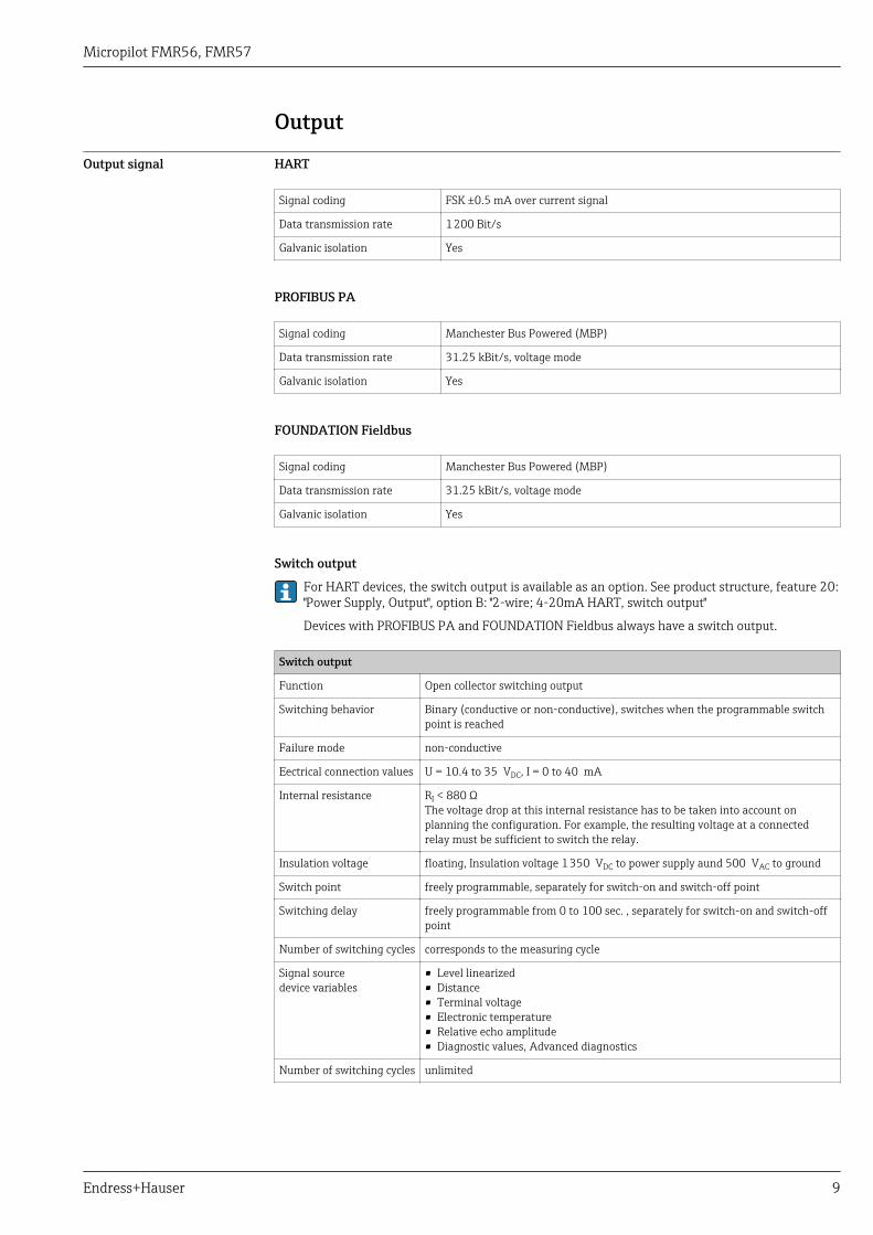
Output signal HART
Signal coding FSK ±0.5 mA over current signal
Data transmission rate 1 200 Bit/s
Galvanic isolation Yes
PROFIBUS PA
Signal coding Manchester Bus Powered (MBP)
Data transmission rate 31.25 kBit/s, voltage mode
Galvanic isolation Yes
FOUNDATION Fieldbus
Signal coding Manchester Bus Powered (MBP)
Data transmission rate 31.25 kBit/s, voltage mode
Galvanic isolation Yes
Switch output
For HART devices, the switch output is available as an option. See product structure, feature 20:"Power Supply, Output", option B: "2-wire; 4-20mA HART, switch output"
Devices with PROFIBUS PA and FOUNDATION Fieldbus always have a switch output.
Switch output
Function Open collector switching output
Switching behavior Binary (conductive or non-conductive), switches when the programmable switchpoint is reached
Failure mode non-conductive
Eectrical connection values U = 10.4 to 35 VDC, I = 0 to 40 mA
Internal resistance RI < 880 ΩThe voltage drop at this internal resistance has to be taken into account onplanning the configuration. For example, the resulting voltage at a connectedrelay must be sufficient to switch the relay.
Insulation voltage floating, Insulation voltage 1 350 VDC to power supply aund 500 VAC to ground
Switch point freely programmable, separately for switch-on and switch-off point
Switching delay freely programmable from 0 to 100 sec. , separately for switch-on and switch-offpoint
Number of switching cycles corresponds to the measuring cycle
Signal sourcedevice variables
• Level linearized• Distance• Terminal voltage• Electronic temperature• Relative echo amplitude• Diagnostic values, Advanced diagnostics
Number of switching cycles unlimited
Micropilot FMR56, FMR57
10 Endress+Hauser
Signal on alarm Depending on the interface, failure information is displayed as follows:• Current output (for HART devices)
– Failsafe mode selectable (in accordance with NAMUR Recommendation NE 43):Minimum alarm: 3.6 mAMaximum alarm (= factory setting): 22 mA
– Failsafe mode with user-selectable value: 3.59 to 22.5 mA• Local display
– Status signal (in accordance with NAMUR Recommendation NE 107)– Plain text display
• Operating tool via digital communication (HART, PROFIBUS PA, FOUNDATION Fieldbus) orservice interface (CDI)– Status signal (in accordance with NAMUR Recommendation NE 107)– Plain text display
Linearization The linearization function of the device allows the conversion of the measured value into any unit oflength or volume. Linearization tables for calculating the volume in cylindrical tanks are pre-programmed. Other tables of up to 32 value pairs can be entered manually or semi-automatically.
Galvanic isolation All circuits for the outputs are galvanically isolated from each other.
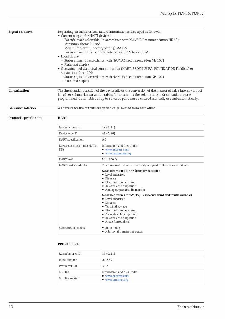
Protocol-specific data HART
Manufacturer ID 17 (0x11)
Device type ID 41 (0x28)
HART specification 6.0
Device description files (DTM,DD)
Information and files under:• www.endress.com• www.hartcomm.org
HART load Min. 250 Ω
HART device variables The measured values can be freely assigned to the device variables.
Measured values for PV (primary variable)• Level linearized• Distance• Electronic temperature• Relative echo amplitude• Analog output adv. diagnostics
Measured values for SV, TV, FV (second, third and fourth variable)• Level linearized• Distance• Terminal voltage• Electronic temperature• Absolute echo amplitude• Relative echo amplitude• Area of incoupling
Supported functions • Burst mode• Additional transmitter status
PROFIBUS PA
Manufacturer ID 17 (0x11)
Ident number 0x1559
Profile version 3.02
GSD file Information and files under:• www.endress.com• www.profibus.orgGSD file version
Micropilot FMR56, FMR57
Endress+Hauser 11
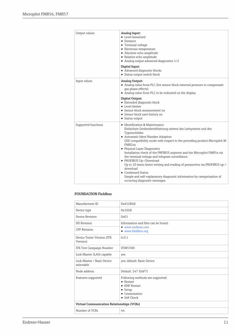
Output values Analog Input:• Level linearized• Distance• Terminal voltage• Electronic temperature• Absolute echo amplitude• Relative echo amplitude• Analog output advanced diagnostics 1/2
Digital Input:• Advanced diagnostic blocks• Status output switch block
Input values Analog Output:• Analog value from PLC (for sensor block external pressure to compensate
gas phase effects)• Analog value from PLC to be indicated on the display
Digital Output:• Extended diagnostic block• Level limiter• Sensor block measurement on• Sensor block save history on• Status output
Supported functions • Identification & MaintenanceEinfachste Geräteidentifizierung seitens des Leitsystems und desTypenschildes
• Automatic Ident Number AdoptionGSD compatibility mode with respect to the preceding product Micropilot MFMR2xx
• Physical Layer DiagnosticsInstallation check of the PRFIBUS segment and the Micropilot FMR5x viathe terminal voltage and telegram surveillance.
• PROFIBUS Up-/DownloadUp to 10 times faster writing and reading of parameters via PROFIBUS up-/download
• Condensed StatusSimple and self-explanatory diagnostic information by categorization ofoccurring diagnostic messages.
FOUNDATION Fieldbus
Manufacturer ID 0x452B48
Device type 0x1028
Device Revision 0x01
DD Revision Information and files can be found:• www.endress.com• www.fieldbus.orgCFF Revision
Device Tester Version (ITKVersion)
6.0.1
ITK Test Campaign Number IT085300
Link Master (LAS) capable yes
Link Master / Basic Deviceselectable
yes; default: Basic Device
Node address Default: 247 (0xF7)
Features supported Following methods are supported:• Restart• ENP Restart• Setup• Linearization• Self Check
Virtual Communication Relationships (VCRs)
Number of VCRs 44
Micropilot FMR56, FMR57
12 Endress+Hauser
Number of Link Objects in VFD 50
Permanent entries 1
Client VCRs 0
Server VCRs 10
Source VCRs 43
Sink VCRs 0
Subscriber VCRs 43
Publisher VCRs 43
Device Link Capabilities
Slot time 4
Min. inter PDU delay 8
Max. response delay 20
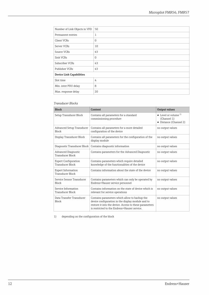
Transducer Blocks
Block Content Output values
Setup Transducer Block Contains all parameters for a standardcommissioning procedure
• Level or volume 1)
(Channel 1)• Distance (Channel 2)
Advanced Setup TransducerBlock
Contains all parameters for a more detailedconfiguration of the device
no output values
Display Transducer Block Contains all parameters for the configuration of thedisplay module
no output values
Diagnostic Transducer Block Contains diagnostic information no output values
Advanced DiagnosticTransducer Block
Contains parameters for the Advanced Diagnostic no output values
Expert ConfigurationTransducer Block
Contains parameters which require detailedknowledge of the functionalities of the device
no output values
Expert InformationTransducer Block
Contains information about the state of the device no output values
Service Sensor TransducerBlock
Contains parameters which can only be operated byEndress+Hauser service personnel
no output values
Service InformationTransducer Block
Contains information on the state of device which isrelevant for service operations
no output values
Data Transfer TransducerBlock
Contains parameters which allow to backup thedevice configuration in the display module and torestore it into the device. Access to these parametersis restricted to the Endress+Hauser service.
no output values
1) depending on the configuration of the block
Micropilot FMR56, FMR57
Endress+Hauser 13
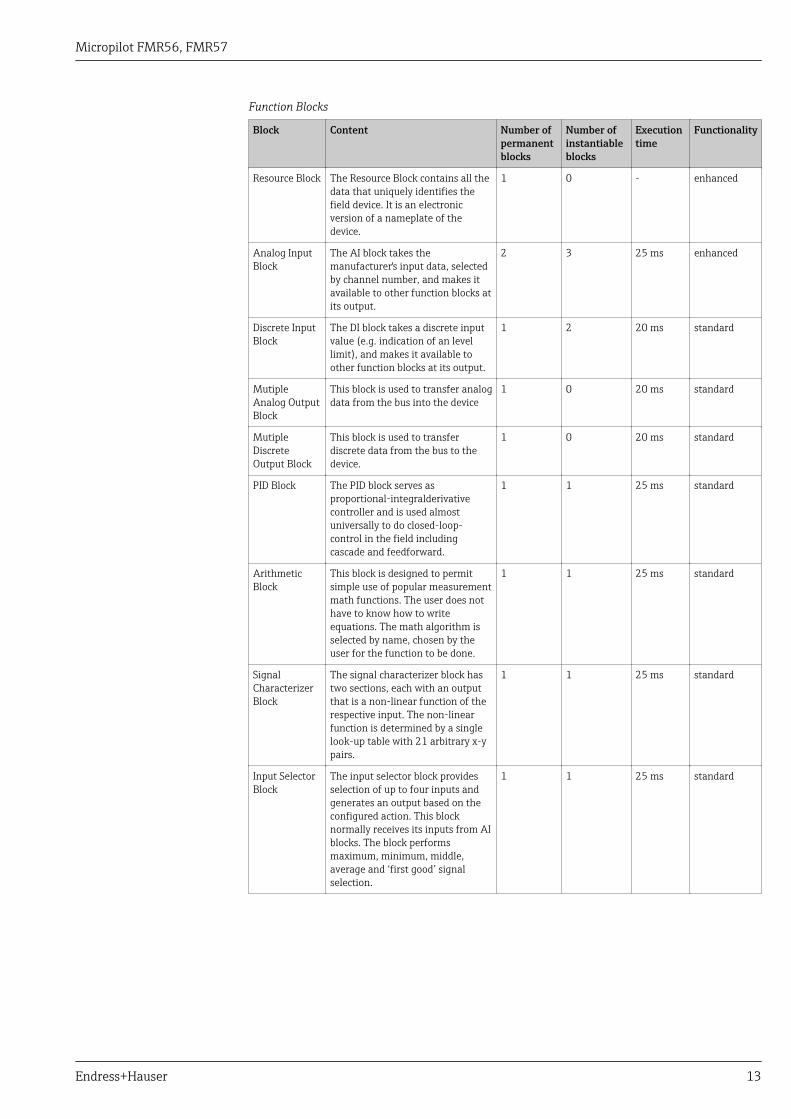
Function Blocks
Block Content Number ofpermanentblocks
Number ofinstantiableblocks
Executiontime
Functionality
Resource Block The Resource Block contains all thedata that uniquely identifies thefield device. It is an electronicversion of a nameplate of thedevice.
1 0 - enhanced
Analog InputBlock
The AI block takes themanufacturer's input data, selectedby channel number, and makes itavailable to other function blocks atits output.
2 3 25 ms enhanced
Discrete InputBlock
The DI block takes a discrete inputvalue (e.g. indication of an levellimit), and makes it available toother function blocks at its output.
1 2 20 ms standard
MutipleAnalog OutputBlock
This block is used to transfer analogdata from the bus into the device
1 0 20 ms standard
MutipleDiscreteOutput Block
This block is used to transferdiscrete data from the bus to thedevice.
1 0 20 ms standard
PID Block The PID block serves asproportional-integralderivativecontroller and is used almostuniversally to do closed-loop-control in the field includingcascade and feedforward.
1 1 25 ms standard
ArithmeticBlock
This block is designed to permitsimple use of popular measurementmath functions. The user does nothave to know how to writeequations. The math algorithm isselected by name, chosen by theuser for the function to be done.
1 1 25 ms standard
SignalCharacterizerBlock
The signal characterizer block hastwo sections, each with an outputthat is a non-linear function of therespective input. The non-linearfunction is determined by a singlelook-up table with 21 arbitrary x-ypairs.
1 1 25 ms standard
Input SelectorBlock
The input selector block providesselection of up to four inputs andgenerates an output based on theconfigured action. This blocknormally receives its inputs from AIblocks. The block performsmaximum, minimum, middle,average and ‘first good’ signalselection.
1 1 25 ms standard
Micropilot FMR56, FMR57
14 Endress+Hauser
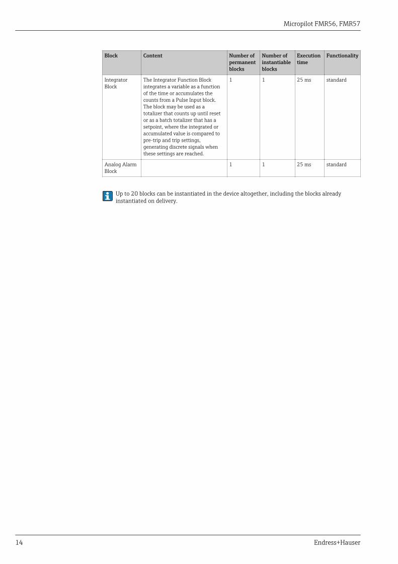
Block Content Number ofpermanentblocks
Number ofinstantiableblocks
Executiontime
Functionality
IntegratorBlock
The Integrator Function Blockintegrates a variable as a functionof the time or accumulates thecounts from a Pulse Input block.The block may be used as atotalizer that counts up until resetor as a batch totalizer that has asetpoint, where the integrated oraccumulated value is compared topre-trip and trip settings,generating discrete signals whenthese settings are reached.
1 1 25 ms standard
Analog AlarmBlock
1 1 25 ms standard
Up to 20 blocks can be instantiated in the device altogether, including the blocks alreadyinstantiated on delivery.
Micropilot FMR56, FMR57
Endress+Hauser 15
Power supply
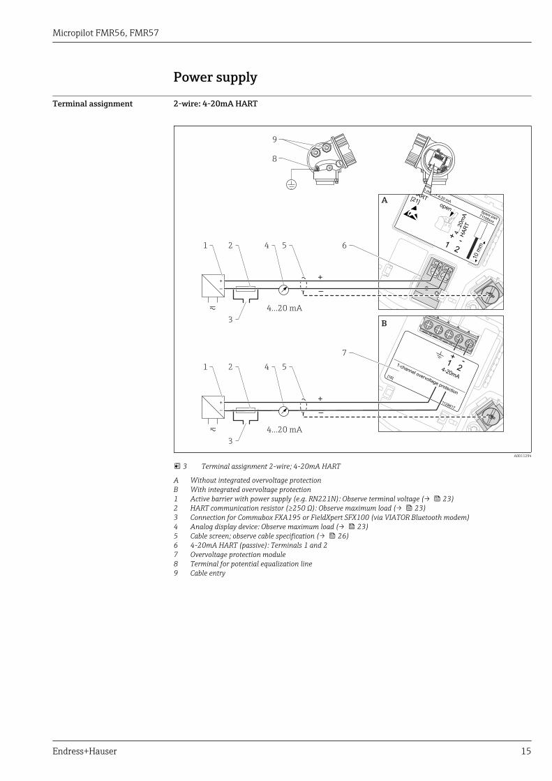
Terminal assignment 2-wire: 4-20mA HART
+
–
4...20 mA
4...20 mA
5
5
4
4
1
1
2
2
8
9
3
3
+
+
–
–
1+
2
4...2
0m
AH
AR
T
10
mm
Spare part71108xxx
2- wire level4-20 mA
4-20 mA
HART[21]open
-
1+
24-20mA
1-channel overvoltage protection
-
71128617
[16]
A
+
–
7
B
6
!
!
A0011294
3 Terminal assignment 2-wire; 4-20mA HART
A Without integrated overvoltage protectionB With integrated overvoltage protection1 Active barrier with power supply (e.g. RN221N): Observe terminal voltage (→ 23)2 HART communication resistor (≥250 Ω): Observe maximum load (→ 23)3 Connection for Commubox FXA195 or FieldXpert SFX100 (via VIATOR Bluetooth modem)4 Analog display device: Observe maximum load (→ 23)5 Cable screen; observe cable specification (→ 26)6 4-20mA HART (passive): Terminals 1 and 27 Overvoltage protection module8 Terminal for potential equalization line9 Cable entry
Micropilot FMR56, FMR57
16 Endress+Hauser
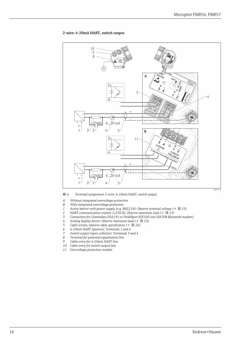
2-wire: 4-20mA HART, switch output
1
3+
+
2
4
4-20mA/FIELDBUS
4-20mA/2-channel overvoltage protection
-
-
71128619
[17]
B
1+
2
4...2
0m
AH
AR
T
10
mm
Spare part71108xxx
2- wire4-20 mAPFS
HART[02/03] open
-
A
1+
2-3
+
4-
10
9
8
7
11
+
+
-
-
2
2
3
3
4
4
6
5
5
1
1
4...20 mA
4...20 mA
³ W250
³ W250
3+
3+
4-
4-
+
+
–
–
A0013759
4 Terminal assignment 2-wire; 4-20mA HART, switch output
A Without integrated overvoltage protectionB With integrated overvoltage protection1 Active barrier with power supply (e.g. RN221N): Observe terminal voltage (→ 23)2 HART communication resistor (≥250 Ω): Observe maximum load (→ 23)3 Connection for Commubox FXA195 or FieldXpert SFX100 (via VIATOR Bluetooth modem)4 Analog display device: Observe maximum load (→ 23)5 Cable screen; observe cable specification (→ 26)6 4-20mA HART (passive): Terminals 1 and 27 Switch output (open collector): Terminals 3 and 48 Terminal for potential equalization line9 Cable entry for 4-20mA HART line10 Cable entry for switch output line11 Overvoltage protection module
Micropilot FMR56, FMR57
Endress+Hauser 17
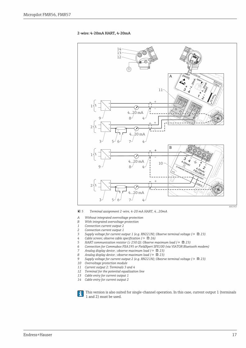
2-wire: 4-20mA HART, 4-20mA
1
3+
+
2
4 4...2
0m
AH
AR
T4...2
0m
A
10
mm
Spare part71108xxx
2- wire level4-20 mA
4-20 mA
HART[04/05] open
-
-11
A
1
3+
+
2
4
4-20mA/FIELDBUS
4-20mA/2-channel overvoltage protection
-
-
71128619
[17]
14
13
12
+
+
+
++
-
-
-
-
1
1
2
2
3
3
9
9
5
5
8
8
6
6
7
7
4
4
4
4
+
+
–
–
+
+
–
–
4...20 mA
4...20 mA
10
B
4...20 mA
4...20 mA
A0013923
5 Terminal assignment 2-wire, 4-20 mA HART, 4...20mA
A Without integrated overvoltage protectionB With integrated overvoltage protection1 Connection current output 22 Connection current output 13 Supply voltage for current output 1 (e.g. RN221N); Observe terminal voltage (→ 23)4 Cable screen; observe cable specification (→ 26)5 HART communication resistor (≥ 250 Ω): Observe maximum load (→ 23)6 Connection for Commubox FXA195 or FieldXpert SFX100 (via VIATOR Bluetooth modem)7 Analog display device ; observe maximum load (→ 23)8 Analog display device ; observe maximum load (→ 23)9 Supply voltage for current output 2 (e.g. RN221N); Obesrve terminal voltage (→ 23)10 Overvoltage protection module11 Current output 2: Terminals 3 and 412 Terminal for the potential equalization line13 Cable entry for current output 114 Cable entry for current output 2
This version is also suited for single-channel operation. In this case, current output 1 (terminals1 and 2) must be used.
Micropilot FMR56, FMR57
18 Endress+Hauser
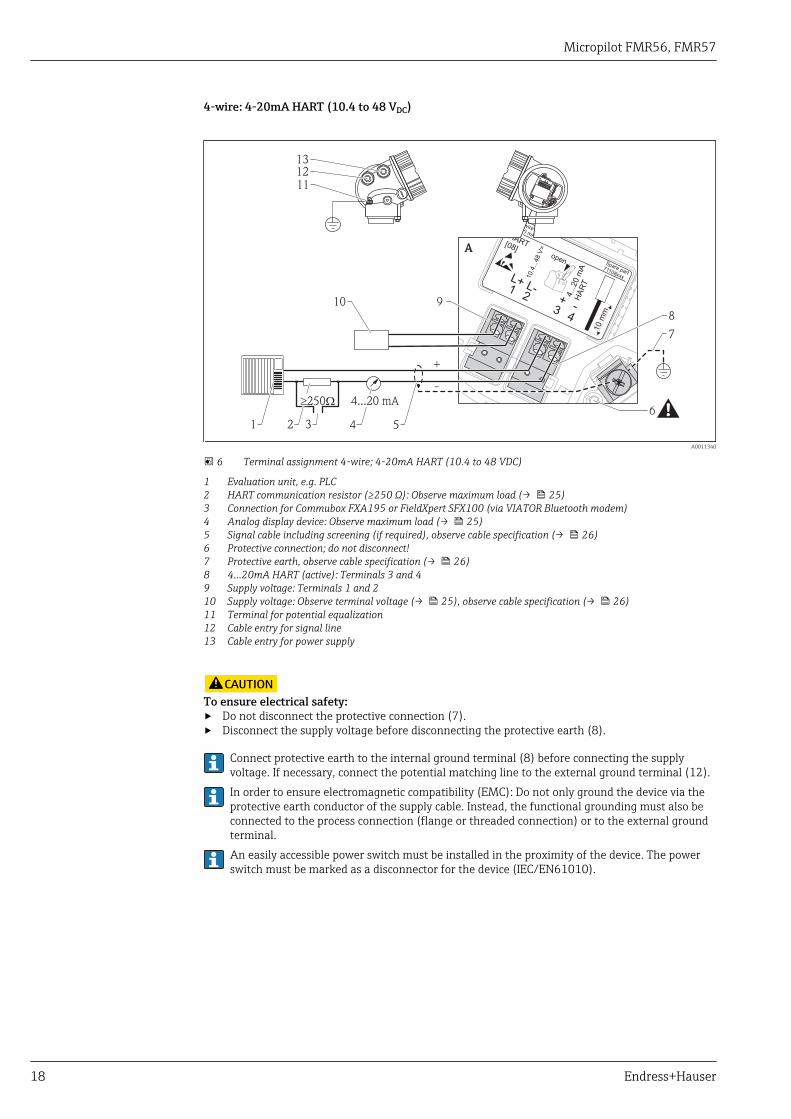
4-wire: 4-20mA HART (10.4 to 48 VDC)
3
1+
L+
4
2 4...2
0m
AH
AR
T
10.4
...4
8V
=
10
mm
Spare part71108xxx
2- wire4-20 mAHART[08]open
-
L-
A
13
12
11
910
+
-
2 3 4
6
7
8
51
4...20 mA³ W250
A0011340
6 Terminal assignment 4-wire; 4-20mA HART (10.4 to 48 VDC)
1 Evaluation unit, e.g. PLC2 HART communication resistor (≥250 Ω): Observe maximum load (→ 25)3 Connection for Commubox FXA195 or FieldXpert SFX100 (via VIATOR Bluetooth modem)4 Analog display device: Observe maximum load (→ 25)5 Signal cable including screening (if required), observe cable specification (→ 26)6 Protective connection; do not disconnect!7 Protective earth, observe cable specification (→ 26)8 4...20mA HART (active): Terminals 3 and 49 Supply voltage: Terminals 1 and 210 Supply voltage: Observe terminal voltage (→ 25), observe cable specification (→ 26)11 Terminal for potential equalization12 Cable entry for signal line13 Cable entry for power supply
!CAUTIONTo ensure electrical safety:‣ Do not disconnect the protective connection (7).‣ Disconnect the supply voltage before disconnecting the protective earth (8).
Connect protective earth to the internal ground terminal (8) before connecting the supplyvoltage. If necessary, connect the potential matching line to the external ground terminal (12).In order to ensure electromagnetic compatibility (EMC): Do not only ground the device via theprotective earth conductor of the supply cable. Instead, the functional grounding must also beconnected to the process connection (flange or threaded connection) or to the external groundterminal.An easily accessible power switch must be installed in the proximity of the device. The powerswitch must be marked as a disconnector for the device (IEC/EN61010).
Micropilot FMR56, FMR57
Endress+Hauser 19
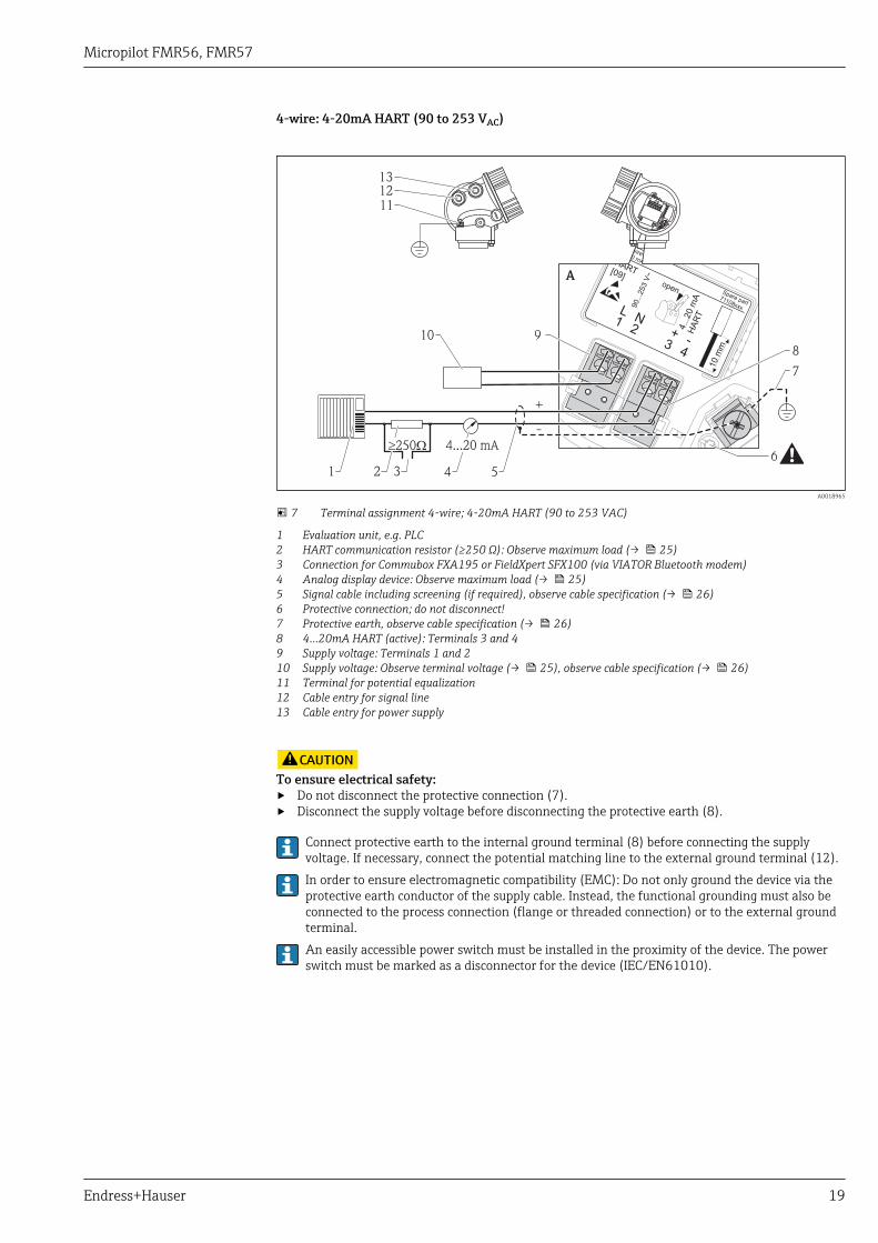
4-wire: 4-20mA HART (90 to 253 VAC)
3
1+
L
4
2 4...2
0m
AH
AR
T
90...2
53
V~
10
mm
Spare part71108xxx
2- wire4-20 mAHART[09]open
-
N
A
13
12
11
910
+
-
2 3 4
6
7
8
51
4...20 mA³ W250
A0018965
7 Terminal assignment 4-wire; 4-20mA HART (90 to 253 VAC)
1 Evaluation unit, e.g. PLC2 HART communication resistor (≥250 Ω): Observe maximum load (→ 25)3 Connection for Commubox FXA195 or FieldXpert SFX100 (via VIATOR Bluetooth modem)4 Analog display device: Observe maximum load (→ 25)5 Signal cable including screening (if required), observe cable specification (→ 26)6 Protective connection; do not disconnect!7 Protective earth, observe cable specification (→ 26)8 4...20mA HART (active): Terminals 3 and 49 Supply voltage: Terminals 1 and 210 Supply voltage: Observe terminal voltage (→ 25), observe cable specification (→ 26)11 Terminal for potential equalization12 Cable entry for signal line13 Cable entry for power supply
!CAUTIONTo ensure electrical safety:‣ Do not disconnect the protective connection (7).‣ Disconnect the supply voltage before disconnecting the protective earth (8).
Connect protective earth to the internal ground terminal (8) before connecting the supplyvoltage. If necessary, connect the potential matching line to the external ground terminal (12).In order to ensure electromagnetic compatibility (EMC): Do not only ground the device via theprotective earth conductor of the supply cable. Instead, the functional grounding must also beconnected to the process connection (flange or threaded connection) or to the external groundterminal.An easily accessible power switch must be installed in the proximity of the device. The powerswitch must be marked as a disconnector for the device (IEC/EN61010).
Micropilot FMR56, FMR57
20 Endress+Hauser
PROFIBUS PA / FOUNDATION Fieldbus
1
3+
+
2
4
FIELDBUS
2-channel overvoltage protection
-
-
71128619
[17]
4-20mA/
4-20mA/
B
1
1+
+
2
2 FIE
LD
BU
S
Spare part71023457
PA/FF[06/07]
FIELDBUS
-
-
1
3+
+
2
4 PA
/FF
10
mm
Spare part71108xxx
2- wire level4-20 mA
PFS
FIELDBUS[26/27] open
-
-
A
4
1
1
2
3
6
5
3+
3+
4-
4-
A0011341
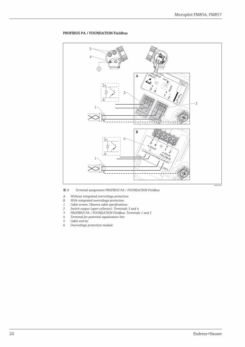
8 Terminal assignment PROFIBUS PA / FOUNDATION Fieldbus
A Without integrated overvoltage protectionB With integrated overvoltage protection1 Cable screen: Observe cable specifications2 Switch output (open collector): Terminals 3 and 43 PROFIBUS PA / FOUNDATION Fieldbus: Terminals 1 and 24 Terminal for potential equalization line5 Cable entries6 Overvoltage protection module
Micropilot FMR56, FMR57
Endress+Hauser 21
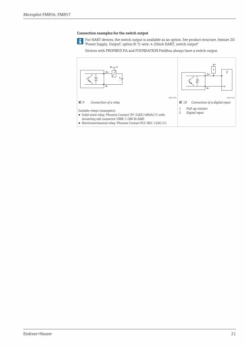
Connection examples for the switch output
For HART devices, the switch output is available as an option. See product structure, feature 20:"Power Supply, Output", option B: "2-wire; 4-20mA HART, switch output"
Devices with PROFIBUS PA and FOUNDATION Fieldbus always have a switch output.
3+
+-
4-
A0015909
9 Connection of a relay
Suitable relays (examples):• Solid-state relay: Phoenix Contact OV-24DC/480AC/5 with
mounting rail connector UMK-1 OM-R/AMS• Electromechanical relay: Phoenix Contact PLC-RSC-12DC/21
3+2
1
+
4-
A0015910
10 Connection of a digital input
1 Pull-up resistor2 Digital input
Micropilot FMR56, FMR57
22 Endress+Hauser
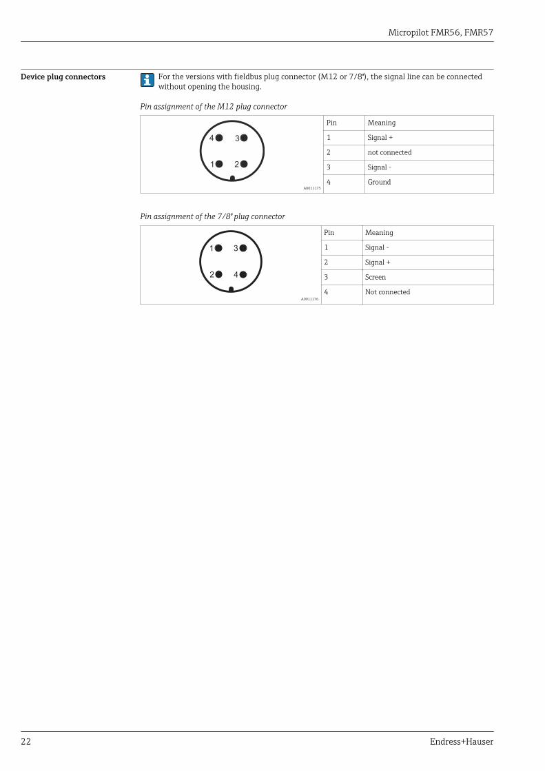
Device plug connectors For the versions with fieldbus plug connector (M12 or 7/8"), the signal line can be connectedwithout opening the housing.
Pin assignment of the M12 plug connector
21
34
A0011175
Pin Meaning
1 Signal +
2 not connected
3 Signal -
4 Ground
Pin assignment of the 7/8" plug connector
2
1
4
3
A0011176
Pin Meaning
1 Signal -
2 Signal +
3 Screen
4 Not connected
Micropilot FMR56, FMR57
Endress+Hauser 23
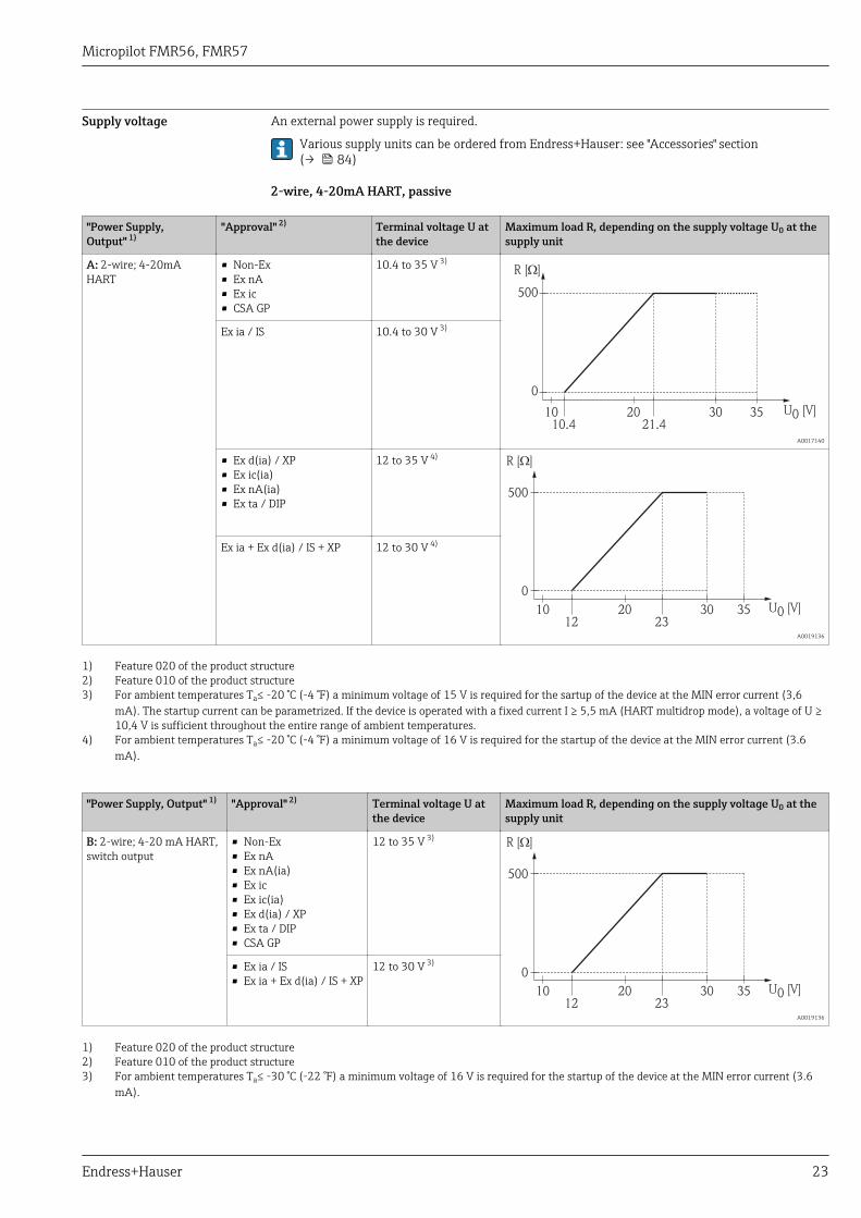
Supply voltage An external power supply is required.
Various supply units can be ordered from Endress+Hauser: see "Accessories" section(→ 84)
2-wire, 4-20mA HART, passive
"Power Supply,Output" 1)
"Approval" 2) Terminal voltage U atthe device
Maximum load R, depending on the supply voltage U0 at thesupply unit
A: 2-wire; 4-20mAHART
• Non-Ex• Ex nA• Ex ic• CSA GP
10.4 to 35 V 3)R [ ]?
U0 [V]1010.4 21.4
20 30 35
0
500
A0017140
Ex ia / IS 10.4 to 30 V 3)
• Ex d(ia) / XP• Ex ic(ia)• Ex nA(ia)• Ex ta / DIP
12 to 35 V 4)R [ ]W
U0 [V]1012 23
20 30 35
0
500
A0019136
Ex ia + Ex d(ia) / IS + XP 12 to 30 V 4)
1) Feature 020 of the product structure2) Feature 010 of the product structure3) For ambient temperatures Ta≤ -20 °C (-4 °F) a minimum voltage of 15 V is required for the sartup of the device at the MIN error current (3,6
mA). The startup current can be parametrized. If the device is operated with a fixed current I ≥ 5,5 mA (HART multidrop mode), a voltage of U ≥10,4 V is sufficient throughout the entire range of ambient temperatures.
4) For ambient temperatures Ta≤ -20 °C (-4 °F) a minimum voltage of 16 V is required for the startup of the device at the MIN error current (3.6mA).
"Power Supply, Output" 1) "Approval" 2) Terminal voltage U atthe device
Maximum load R, depending on the supply voltage U0 at thesupply unit
B: 2-wire; 4-20 mA HART,switch output
• Non-Ex• Ex nA• Ex nA(ia)• Ex ic• Ex ic(ia)• Ex d(ia) / XP• Ex ta / DIP• CSA GP
12 to 35 V 3)R [ ]W
U0 [V]1012 23
20 30 35
0
500
A0019136
• Ex ia / IS• Ex ia + Ex d(ia) / IS + XP
12 to 30 V 3)
1) Feature 020 of the product structure2) Feature 010 of the product structure3) For ambient temperatures Ta≤ -30 °C (-22 °F) a minimum voltage of 16 V is required for the startup of the device at the MIN error current (3.6
mA).
Micropilot FMR56, FMR57
24 Endress+Hauser
"Power Supply, Output" 1) "Approval" 2) Terminal voltage U at thedevice
Maximum load R, depending on the supply voltage U0 at thesupply unit
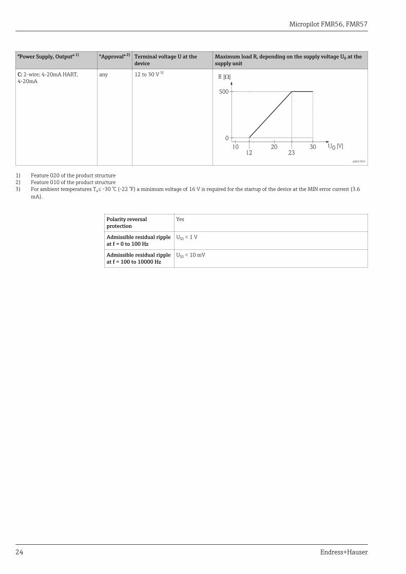
C: 2-wire; 4-20mA HART,4-20mA
any 12 to 30 V 3)R [ ]?
U0 [V]1012 23
20 30
0
500
A0017055
1) Feature 020 of the product structure2) Feature 010 of the product structure3) For ambient temperatures Ta≤ -30 °C (-22 °F) a minimum voltage of 16 V is required for the startup of the device at the MIN error current (3.6
mA).
Polarity reversalprotection
Yes
Admissible residual rippleat f = 0 to 100 Hz
USS < 1 V
Admissible residual rippleat f = 100 to 10000 Hz
USS < 10 mV
Micropilot FMR56, FMR57
Endress+Hauser 25
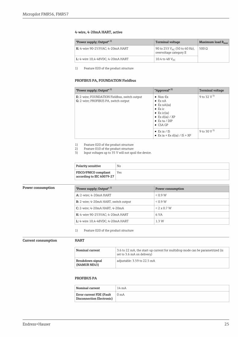
4-wire, 4-20mA HART, active
"Power supply; Output" 1) Terminal voltage Maximum load Rmax
K: 4-wire 90-253VAC; 4-20mA HART 90 to 253 VAC (50 to 60 Hz),overvoltage category II
500 Ω
L: 4-wire 10,4-48VDC; 4-20mA HART 10.4 to 48 VDC
1) Feature 020 of the product structure
PROFIBUS PA, FOUNDATION Fieldbus
"Power supply; Output" 1) "Approval" 2) Terminal voltage
E: 2-wire; FOUNDATION Fieldbus, switch outputG: 2-wire; PROFIBUS PA, switch output
• Non-Ex• Ex nA• Ex nA(ia)• Ex ic• Ex ic(ia)• Ex d(ia) / XP• Ex ta / DIP• CSA GP
9 to 32 V 3)
• Ex ia / IS• Ex ia + Ex d(ia) / IS + XP
9 to 30 V 3)
1) Feature 020 of the product structure2) Feature 010 of the product structure3) Input voltages up to 35 V will not spoil the device.
Polarity sensitive No
FISCO/FNICO compliantaccording to IEC 60079-27
Yes
Power consumption "Power supply; Output" 1) Power consumption
A: 2-wire; 4-20mA HART < 0.9 W
B: 2-wire; 4-20mA HART, switch output < 0.9 W
C: 2-wire; 4-20mA HART, 4-20mA < 2 x 0.7 W
K: 4-wire 90-253VAC; 4-20mA HART 6 VA
L: 4-wire 10,4-48VDC; 4-20mA HART 1.3 W
1) Feature 020 of the product structure
Current consumption HART
Nominal current 3.6 to 22 mA, the start-up current for multidrop mode can be parametrized (isset to 3.6 mA on delivery)
Breakdown signal(NAMUR NE43)
adjustable: 3.59 to 22.5 mA
PROFIBUS PA
Nominal current 14 mA
Error current FDE (FaultDisconnection Electronic)
0 mA
Micropilot FMR56, FMR57
26 Endress+Hauser
FOUNDATION Fieldbus
Device basic current 15 mA
Error current FDE (FaultDisconnection Electronic)
0 mA
FISCO
Ui 17.5 V
Ii 550 mA
Pi 5.5 W
Ci 5 nF
Li 10 μH
Power supply failure • Configuration is retained in the HistoROM (EEPROM).• Error messages (incl. value of operated hours counter) are stored.
Potential equalization No special measures for potential equalization are required.
If the device is designed for hazardous areas, observe the information in the documentation"Safety Instructions" (XA, ZD).
Terminals • Without integrated overvoltage protectionPlug-in spring terminals for wire cross-sections 0.5 to 2.5 mm2 (20 to 14 AWG)
• With integrated overvoltage protectionScrew terminals for wire cross-sections 0.2 to 2.5 mm2 (24 to 14 AWG)
Cable entries • Cable gland (not for Ex d):– Plastics M20x1.5 for cable 5 to 10 mm (0.2 to 0.39 in): non-Ex, ATEX/IECEx/NEPSI Ex ia/ic– Metal M20x1.5 for cable 7 to 10 mm (0.28 to 0.39 in): dust-Ex, FM IS, CSA IS, CSA GP, Ex nA
• Thread for cable entry:– ½" NPT– G ½"– M20 × 1.5
• Connector (only for non-Ex, Ex ic, Ex ia): M12 or 7/8"
Cable specification • Minimum cross-section: (→ 26)• For ambient temperature TU≥60 °C (140 °F): use cable for temperature TU +20 K.
HART
• A normal device cable suffices if only the analog signal is used.• A shielded cable is recommended if using the HART protocol. Observe grounding concept of the
plant.• For 4-wire devices: Standard device cable is sufficient for the power line.
PROFIBUS
Use a twisted, screened two-wire cable, preferably cable type A.For further information on the cable specifications, see Operating Instructions BA00034S"Guidelines for planning and commissioning PROFIBUS DP/PA", PNO Guideline 2.092"PROFIBUS PA User and Installation Guideline" and IEC61158-2 (MBP).
FOUNDATION Fieldbus
Endress+Hauser recommends using twisted, shielded two-wire cables.For further information on the cable specifications, see Operating Instructions BA00013S"FOUNDATION Fieldbus Overview", FOUNDATION Fieldbus Guideline and IEC 61158-2 (MBP).
Micropilot FMR56, FMR57
Endress+Hauser 27
Overvoltage protection If the measuring device is used for level measurement in flammable liquids which requires the use ofovervoltage protection according to DIN EN 60079-14, standard for test procedures 60060-1 (10kA, pulse 8/20 μs), overvoltage protection has to be ensured by an integrated or externalovervoltage protection module.
Integrated overvoltage protection
An integrated overvoltage protection module is available for 2-wire HART as well as PROFIBUS PAand FOUNDATION Fieldbus devices.
Product structure: Feature 610 "Accessory mounted", option NA "Overvoltage protection".
Technical data
Resistance per channel 2 * 0.5 Ω max
Threshold DC voltage 400 to 700 V
Threshold impulse voltage < 800 V
Capacitance at 1 MHz < 1.5 pF
Nominal arrest impulse voltage (⁸⁄₂₀ μs) 10 kA
External overvoltage protection
HAW562 or HAW569 from Endress+Hauser are suited as external overvoltage protection.
For detailed information please refer to the following documents:• HAW562: TI01012K• HAW569: TI01013K
Micropilot FMR56, FMR57
28 Endress+Hauser
Performance characteristics
Reference operatingconditions
• Temperature = +24 °C (+75 °F)±5 °C (±9 °F)• Pressure = 960 mbar abs. (14 psia)±100 mbar (±1.45 psi)• Humidity = 60 %±15 %• Reflector: metal plate with a minimum diameter of 1 m (40 in)• No major interference reflections inside the signal beam
Maximum measured error Typical data under reference operating conditions: DIN EN 61298-2, percentage values in relation tothe span.
Device Value Output
digital analog 1)
FMR56/FMR57 Sum of non-linearity,nonrepeatability andhysteresis
±3 mm (0.12 in) ±0.02 %
Offset/Zero ±4 mm (0.2 in) ±0.03 %
1) Only relevant for 4-20mA current output; add error of the analog value to the digital value.
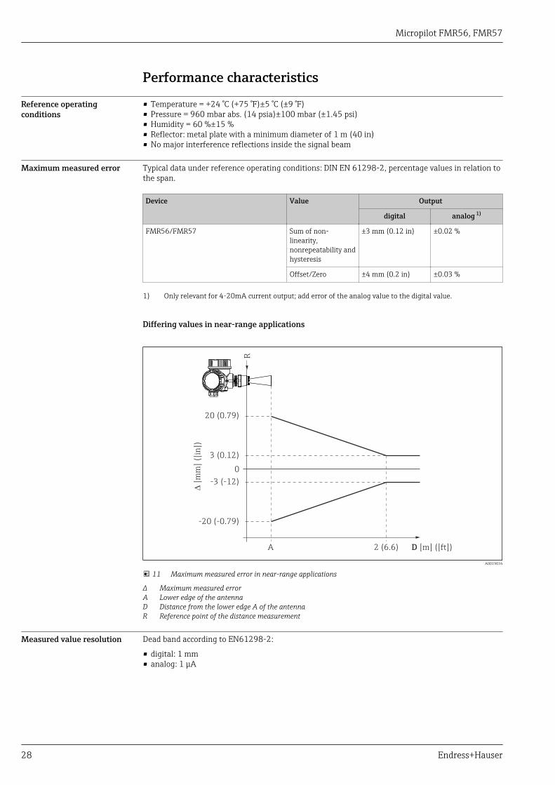
Differing values in near-range applications
3 (0.12)
0
-3 (-12)
A 2 (6.6) D [m] ([ft])
20 (0.79)
-20 (-0.79)
R
D[m
m]
([in
])
A0019034
11 Maximum measured error in near-range applications
Δ Maximum measured errorA Lower edge of the antennaD Distance from the lower edge A of the antennaR Reference point of the distance measurement
Measured value resolution Dead band according to EN61298-2:
• digital: 1 mm• analog: 1 μA
Micropilot FMR56, FMR57
Endress+Hauser 29
Reaction time The reaction time can be parametrized. The following step response times (as per DIN EN61298-2) 1)are valid if the damping is switched off:
Tank height Sampling rate Step response time
<10 m (33 ft) ≥3.6 s–1 < 0.8 s
<70 m (230 ft) ≥2.2 s–1 < 1 s
Influence of ambienttemperature
The measurements are carried out in accordance with EN 61298-3• Digital (HART, PROFIBUS PA, FOUNDATION Fieldbus): average TK = 5 mm/10 K; maximum
15 mm• Analog (current output):
– zero point (4 mA): average TK = 0.02 %/10 K– span (20 mA): average TK = 0.05 %/10 K
1) According to DIN EN 61298-2 the response time is the time which passes after a sudden change of the input signal until the output signal for thefirst time assumes 90% of the steady-state value.
Micropilot FMR56, FMR57
30 Endress+Hauser
Installation
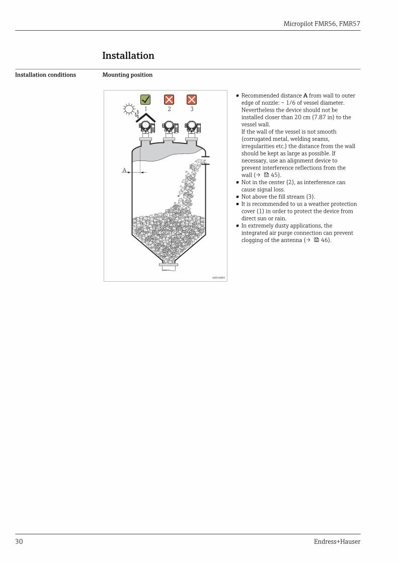
Installation conditions Mounting position
A
1 2 3
A0016883
• Recommended distance A from wall to outeredge of nozzle: ~ 1/6 of vessel diameter.Nevertheless the device should not beinstalled closer than 20 cm (7.87 in) to thevessel wall.If the wall of the vessel is not smooth(corrugated metal, welding seams,irregularities etc.) the distance from the wallshould be kept as large as possible. Ifnecessary, use an alignment device toprevent interference reflections from thewall (→ 45).
• Not in the center (2), as interference cancause signal loss.
• Not above the fill stream (3).• It is recommended to us a weather protection
cover (1) in order to protect the device fromdirect sun or rain.
• In extremely dusty applications, theintegrated air purge connection can preventclogging of the antenna (→ 46).
Micropilot FMR56, FMR57
Endress+Hauser 31
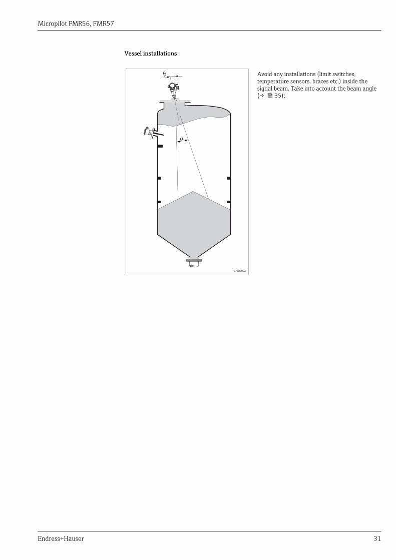
Vessel installations
a
b
A0018946
Avoid any installations (limit switches,temperature sensors, braces etc.) inside thesignal beam. Take into account the beam angle(→ 35):
Micropilot FMR56, FMR57
32 Endress+Hauser
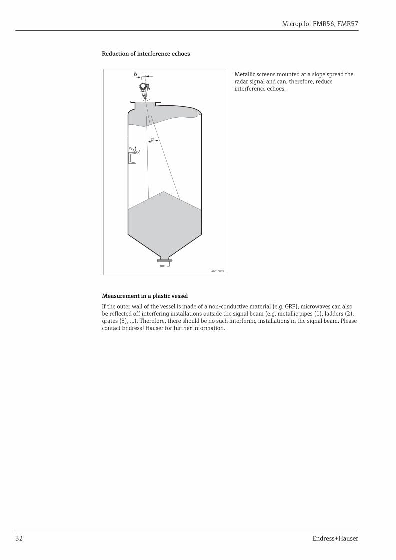
Reduction of interference echoes
a
b
A0016889
Metallic screens mounted at a slope spread theradar signal and can, therefore, reduceinterference echoes.
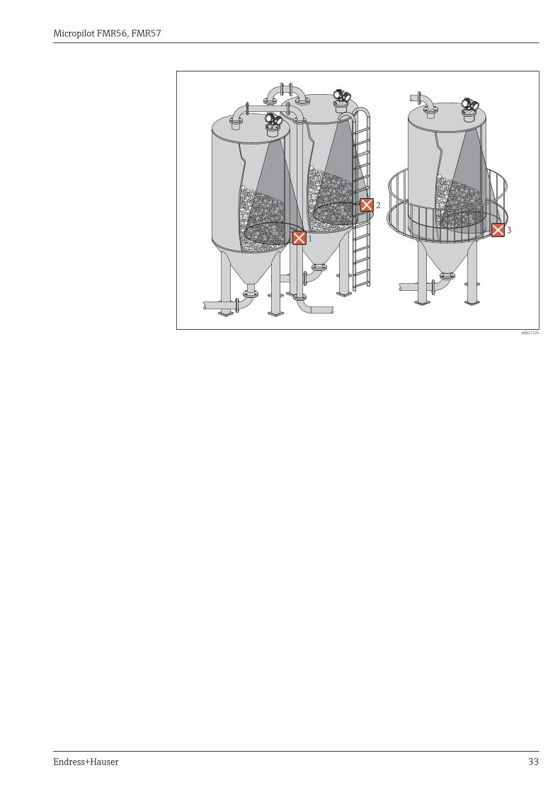
Measurement in a plastic vessel
If the outer wall of the vessel is made of a non-conductive material (e.g. GRP), microwaves can alsobe reflected off interfering installations outside the signal beam (e.g. metallic pipes (1), ladders (2),grates (3), ...). Therefore, there should be no such interfering installations in the signal beam. Pleasecontact Endress+Hauser for further information.
Micropilot FMR56, FMR57
Endress+Hauser 33
2
3
1
A0017125
Micropilot FMR56, FMR57
34 Endress+Hauser
Optimization options
• Antenna sizeThe bigger the antenna, the smaller the beam angle α and the fewer interference echoes(→ 35).
• MappingThe measurement can be optimized by means of electronic suppression of interference echoes.
• Antenna alignmentTake into account the marker on the flange or threaded connection (→ 38).
• Metallic screens mounted at a slopeThey spread the radar signals and can, therefore, reduce interference echoes.
• Variable flange seal (FMR56)Using the variable flange seal, the device can be aligned in the direction of the product surface. Fordetails refer to Operating Instructions BA01048F, chapter "Accessories".
• Alignment device for FMR57In FMR57 with alignment device, the sensor can be optimally aimed within the vessel and thusinterference echoes can be avoided. The maximum angle β is ±15°.In particular, sensor alignment serves to:– prevent interference reflections– extend the maximum possible measuring range in conical outlets
Micropilot FMR56, FMR57
Endress+Hauser 35
Beam angle
a
D
W
aD
_=
22 . . tanW
A0016891
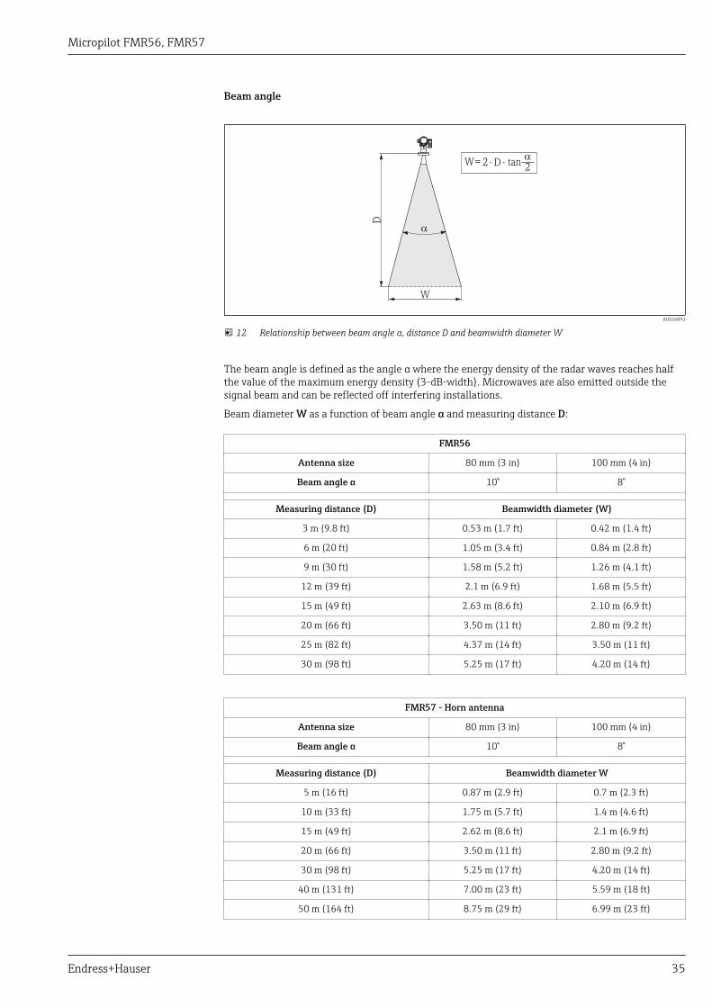
12 Relationship between beam angle α, distance D and beamwidth diameter W
The beam angle is defined as the angle α where the energy density of the radar waves reaches halfthe value of the maximum energy density (3-dB-width). Microwaves are also emitted outside thesignal beam and can be reflected off interfering installations.
Beam diameter W as a function of beam angle α and measuring distance D:
FMR56
Antenna size 80 mm (3 in) 100 mm (4 in)
Beam angle α 10° 8°
Measuring distance (D) Beamwidth diameter (W)
3 m (9.8 ft) 0.53 m (1.7 ft) 0.42 m (1.4 ft)
6 m (20 ft) 1.05 m (3.4 ft) 0.84 m (2.8 ft)
9 m (30 ft) 1.58 m (5.2 ft) 1.26 m (4.1 ft)
12 m (39 ft) 2.1 m (6.9 ft) 1.68 m (5.5 ft)
15 m (49 ft) 2.63 m (8.6 ft) 2.10 m (6.9 ft)
20 m (66 ft) 3.50 m (11 ft) 2.80 m (9.2 ft)
25 m (82 ft) 4.37 m (14 ft) 3.50 m (11 ft)
30 m (98 ft) 5.25 m (17 ft) 4.20 m (14 ft)
FMR57 - Horn antenna
Antenna size 80 mm (3 in) 100 mm (4 in)
Beam angle α 10° 8°
Measuring distance (D) Beamwidth diameter W
5 m (16 ft) 0.87 m (2.9 ft) 0.7 m (2.3 ft)
10 m (33 ft) 1.75 m (5.7 ft) 1.4 m (4.6 ft)
15 m (49 ft) 2.62 m (8.6 ft) 2.1 m (6.9 ft)
20 m (66 ft) 3.50 m (11 ft) 2.80 m (9.2 ft)
30 m (98 ft) 5.25 m (17 ft) 4.20 m (14 ft)
40 m (131 ft) 7.00 m (23 ft) 5.59 m (18 ft)
50 m (164 ft) 8.75 m (29 ft) 6.99 m (23 ft)
Micropilot FMR56, FMR57
36 Endress+Hauser
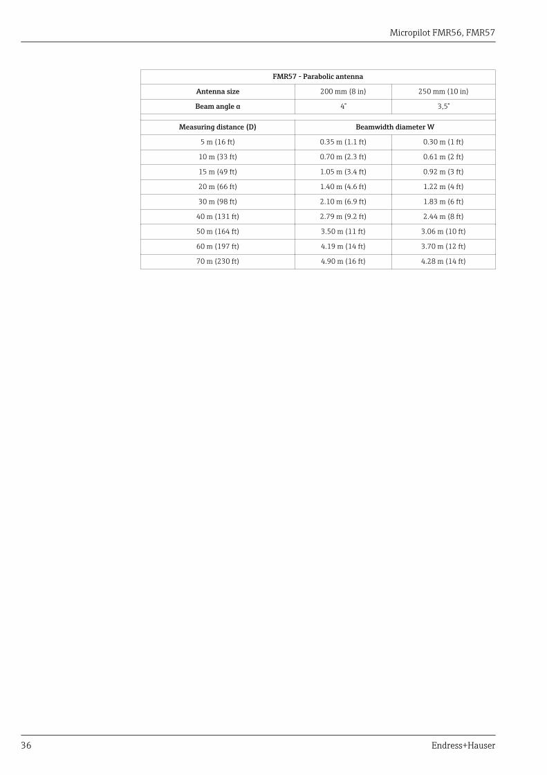
FMR57 - Parabolic antenna
Antenna size 200 mm (8 in) 250 mm (10 in)
Beam angle α 4° 3,5°
Measuring distance (D) Beamwidth diameter W
5 m (16 ft) 0.35 m (1.1 ft) 0.30 m (1 ft)
10 m (33 ft) 0.70 m (2.3 ft) 0.61 m (2 ft)
15 m (49 ft) 1.05 m (3.4 ft) 0.92 m (3 ft)
20 m (66 ft) 1.40 m (4.6 ft) 1.22 m (4 ft)
30 m (98 ft) 2.10 m (6.9 ft) 1.83 m (6 ft)
40 m (131 ft) 2.79 m (9.2 ft) 2.44 m (8 ft)
50 m (164 ft) 3.50 m (11 ft) 3.06 m (10 ft)
60 m (197 ft) 4.19 m (14 ft) 3.70 m (12 ft)
70 m (230 ft) 4.90 m (16 ft) 4.28 m (14 ft)
Micropilot FMR56, FMR57
Endress+Hauser 37
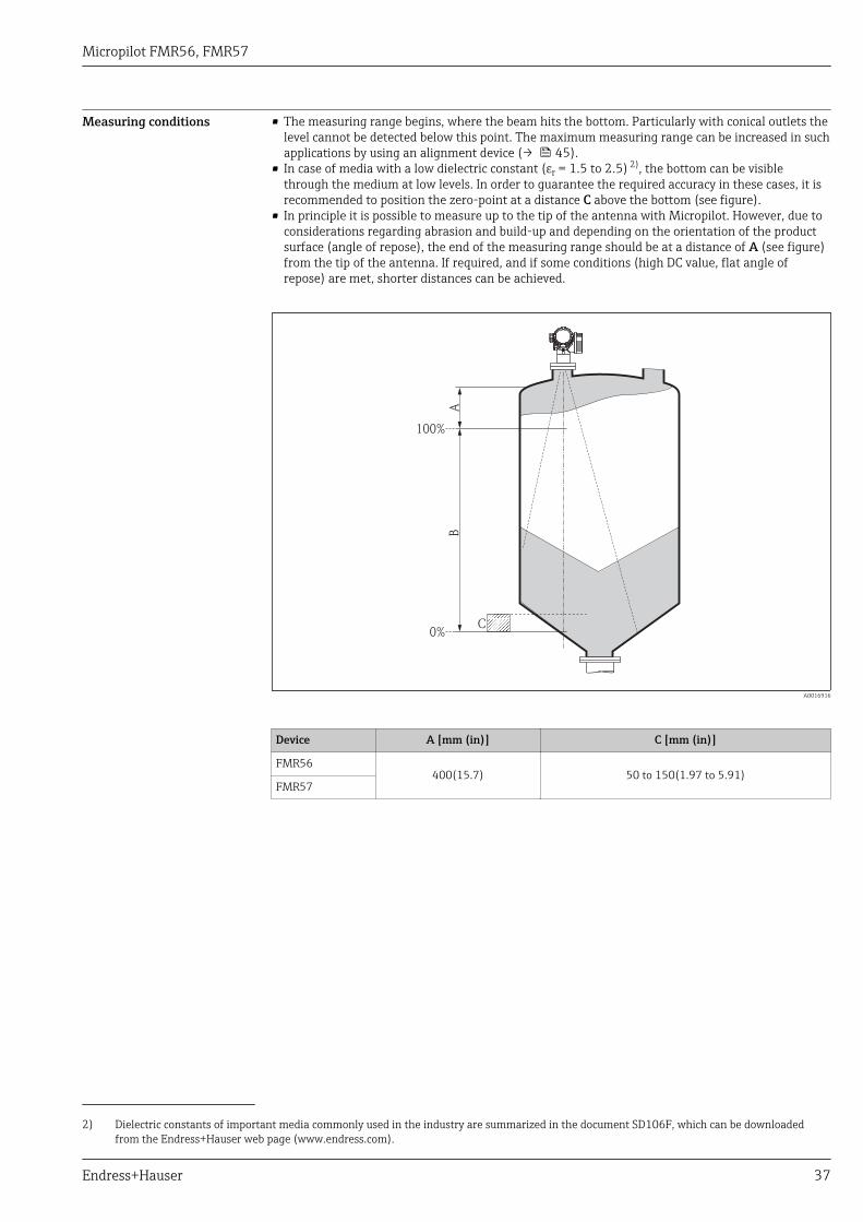
Measuring conditions • The measuring range begins, where the beam hits the bottom. Particularly with conical outlets thelevel cannot be detected below this point. The maximum measuring range can be increased in suchapplications by using an alignment device (→ 45).
• In case of media with a low dielectric constant (εr = 1.5 to 2.5) 2), the bottom can be visiblethrough the medium at low levels. In order to guarantee the required accuracy in these cases, it isrecommended to position the zero-point at a distance C above the bottom (see figure).
• In principle it is possible to measure up to the tip of the antenna with Micropilot. However, due toconsiderations regarding abrasion and build-up and depending on the orientation of the productsurface (angle of repose), the end of the measuring range should be at a distance of A (see figure)from the tip of the antenna. If required, and if some conditions (high DC value, flat angle ofrepose) are met, shorter distances can be achieved.
100%
0%
AB
C
A0016916
Device A [mm (in)] C [mm (in)]
FMR56400(15.7) 50 to 150(1.97 to 5.91)
FMR57
2) Dielectric constants of important media commonly used in the industry are summarized in the document SD106F, which can be downloadedfrom the Endress+Hauser web page (www.endress.com).
Micropilot FMR56, FMR57
38 Endress+Hauser
Installation in vessel (freespace)
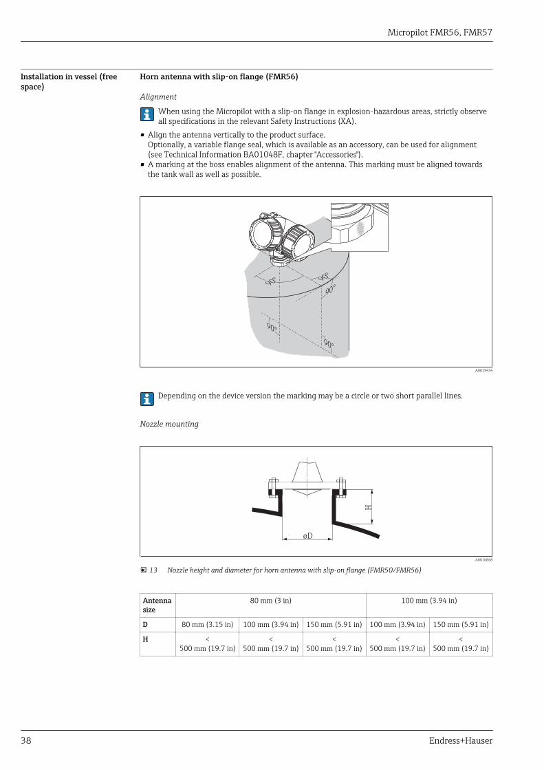
Horn antenna with slip-on flange (FMR56)
Alignment
When using the Micropilot with a slip-on flange in explosion-hazardous areas, strictly observeall specifications in the relevant Safety Instructions (XA).
• Align the antenna vertically to the product surface.Optionally, a variable flange seal, which is available as an accessory, can be used for alignment(see Technical Information BA01048F, chapter "Accessories").
• A marking at the boss enables alignment of the antenna. This marking must be aligned towardsthe tank wall as well as possible.
90°
90°
90°
90°
90°
A0019434
Depending on the device version the marking may be a circle or two short parallel lines.
Nozzle mounting
H
øD
A0016868
13 Nozzle height and diameter for horn antenna with slip-on flange (FMR50/FMR56)
Antennasize
80 mm (3 in) 100 mm (3.94 in)
D 80 mm (3.15 in) 100 mm (3.94 in) 150 mm (5.91 in) 100 mm (3.94 in) 150 mm (5.91 in)
H <500 mm (19.7 in)
<500 mm (19.7 in)
<500 mm (19.7 in)
<500 mm (19.7 in)
<500 mm (19.7 in)
Micropilot FMR56, FMR57
Endress+Hauser 39
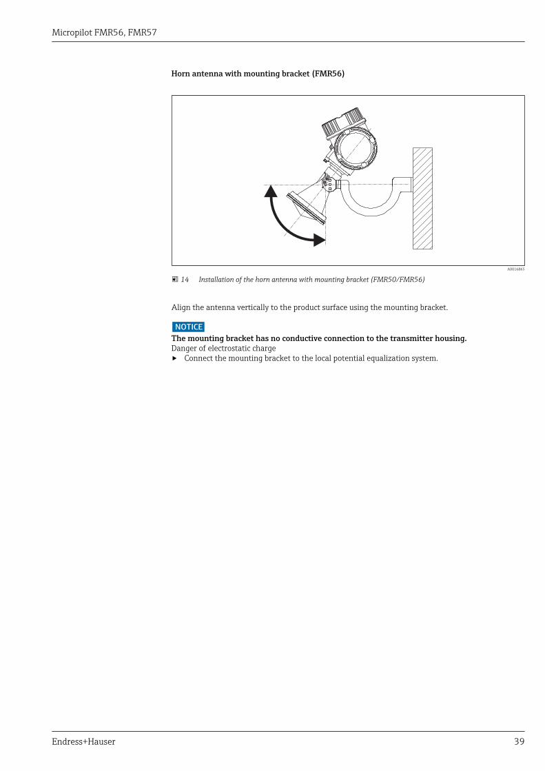
Horn antenna with mounting bracket (FMR56)
A0016865
14 Installation of the horn antenna with mounting bracket (FMR50/FMR56)
Align the antenna vertically to the product surface using the mounting bracket.
NOTICEThe mounting bracket has no conductive connection to the transmitter housing.Danger of electrostatic charge‣ Connect the mounting bracket to the local potential equalization system.
Micropilot FMR56, FMR57
40 Endress+Hauser
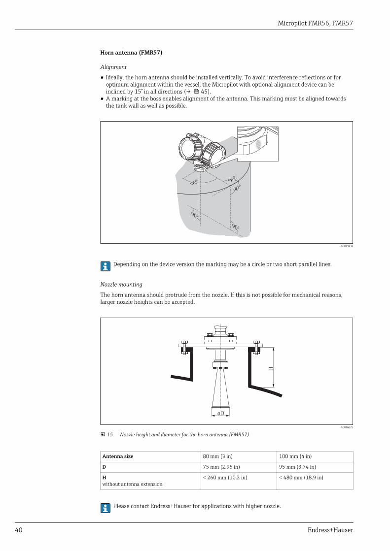
Horn antenna (FMR57)
Alignment
• Ideally, the horn antenna should be installed vertically. To avoid interference reflections or foroptimum alignment within the vessel, the Micropilot with optional alignment device can beinclined by 15° in all directions (→ 45).
• A marking at the boss enables alignment of the antenna. This marking must be aligned towardsthe tank wall as well as possible.
90°
90°
90°
90°
90°
A0019434
Depending on the device version the marking may be a circle or two short parallel lines.
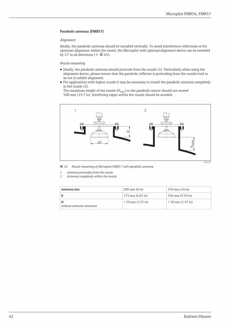
Nozzle mounting
The horn antenna should protrude from the nozzle. If this is not possible for mechanical reasons,larger nozzle heights can be accepted.
H
øD
A0016825
15 Nozzle height and diameter for the horn antenna (FMR57)
Antenna size 80 mm (3 in) 100 mm (4 in)
D 75 mm (2.95 in) 95 mm (3.74 in)
Hwithout antenna extension
< 260 mm (10.2 in) < 480 mm (18.9 in)
Please contact Endress+Hauser for applications with higher nozzle.

Micropilot FMR56, FMR57
Endress+Hauser 41
Threaded connection
• Tighten with the hexagonal nut only.• Tool : Hexagonal wrench 60 mm• Maximum permissible torque: 60 Nm (44 lbf ft)
Micropilot FMR56, FMR57
42 Endress+Hauser
Parabolic antenna (FMR57)
Alignment
Ideally, the parabolic antenna should be installed vertically. To avoid interference reflections or foroptimum alignment within the vessel, the Micropilot with optional alignment device can be swiveledby 15° in all directions (→ 45).
Nozzle mounting
• Ideally, the parabolic antenna should protrude from the nozzle (1). Particularly when using thealignment device, please ensure that the parabolic reflector is protruding from the nozzle/roof soas not to inhibit alignment.
• For applications with higher nozzle it may be necessary to install the parabolic antenna completelyin the nozzle (2).The maximum height of the nozzle (Hmax) to the parabolic mirror should not exceed500 mm (19.7 in). Interfering edges within the nozzle should be avoided.
H
Hm
ax
øD
1 2
A0016827
16 Nozzle mounting of Micropilot FMR57 with parabolic antenna
1 Antenna protrudes from the nozzle2 Antenna completely within the nozzle
Antenna size 200 mm (8 in) 250 mm (10 in)
D 173 mm (6.81 in) 236 mm (9.29 in)
Hwithout antenna extension
< 50 mm (1.97 in) < 50 mm (1.97 in)
Micropilot FMR56, FMR57
Endress+Hauser 43
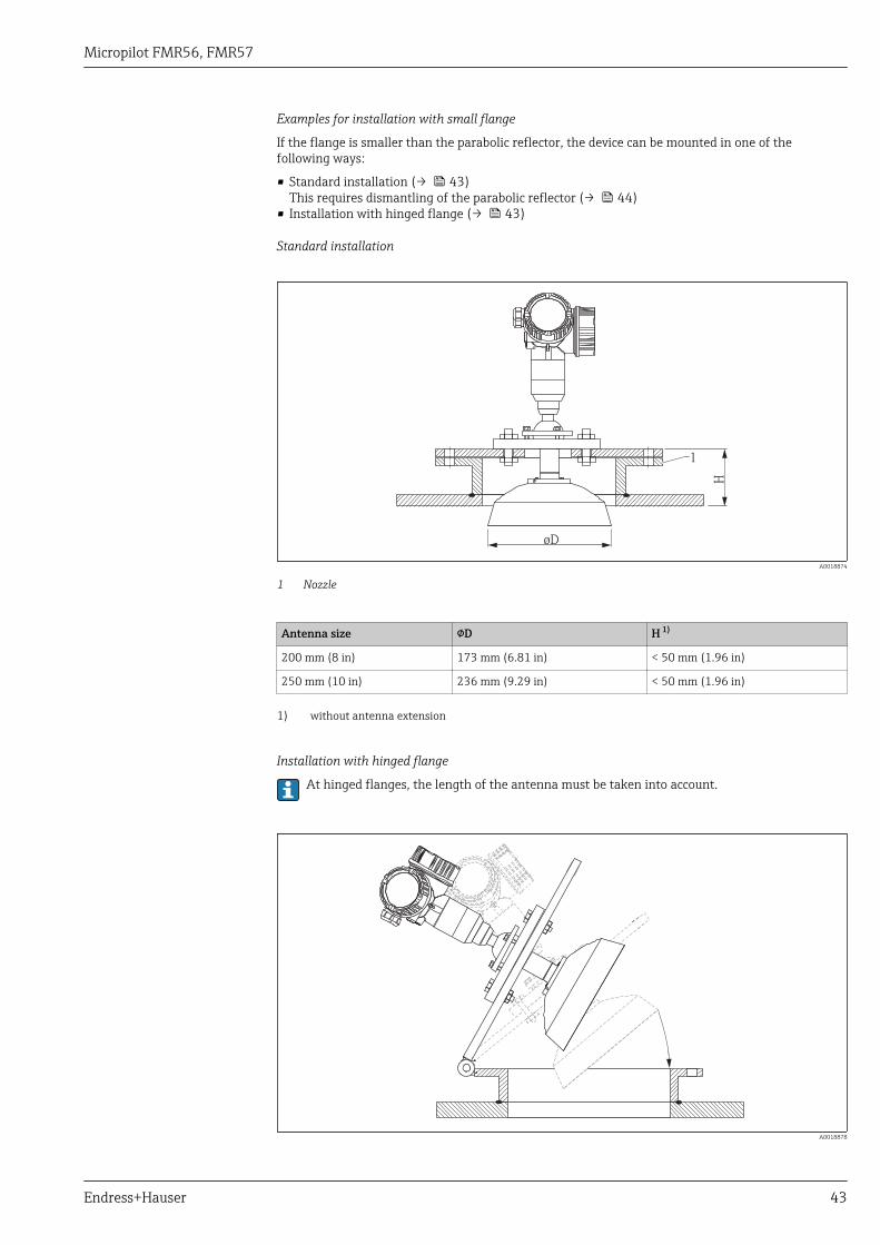
Examples for installation with small flange
If the flange is smaller than the parabolic reflector, the device can be mounted in one of thefollowing ways:
• Standard installation (→ 43)This requires dismantling of the parabolic reflector (→ 44)
• Installation with hinged flange (→ 43)
Standard installation
H
øD
1
A0018874
1 Nozzle
Antenna size D H 1)
200 mm (8 in) 173 mm (6.81 in) < 50 mm (1.96 in)
250 mm (10 in) 236 mm (9.29 in) < 50 mm (1.96 in)
1) without antenna extension
Installation with hinged flange
At hinged flanges, the length of the antenna must be taken into account.
A0018878
Micropilot FMR56, FMR57
44 Endress+Hauser
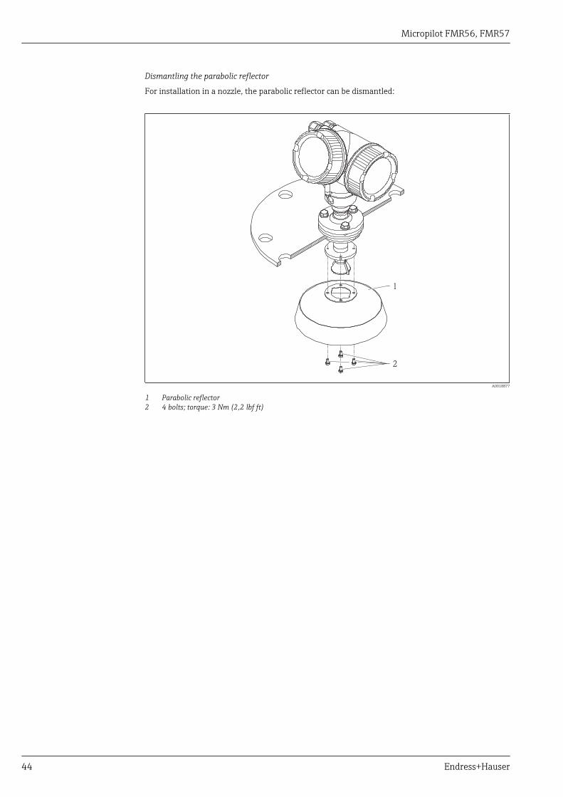
Dismantling the parabolic reflector
For installation in a nozzle, the parabolic reflector can be dismantled:
2
1
A0018877
1 Parabolic reflector2 4 bolts; torque: 3 Nm (2,2 lbf ft)
Micropilot FMR56, FMR57
Endress+Hauser 45
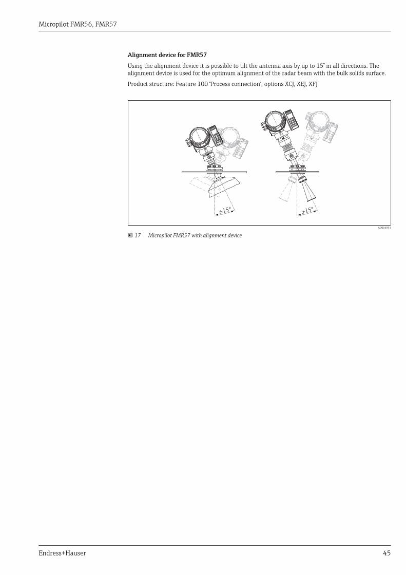
Alignment device for FMR57
Using the alignment device it is possible to tilt the antenna axis by up to 15° in all directions. Thealignment device is used for the optimum alignment of the radar beam with the bulk solids surface.
Product structure: Feature 100 "Process connection", options XCJ, XEJ, XFJ
±15° ±15°
A0016931
17 Micropilot FMR57 with alignment device
Micropilot FMR56, FMR57
46 Endress+Hauser
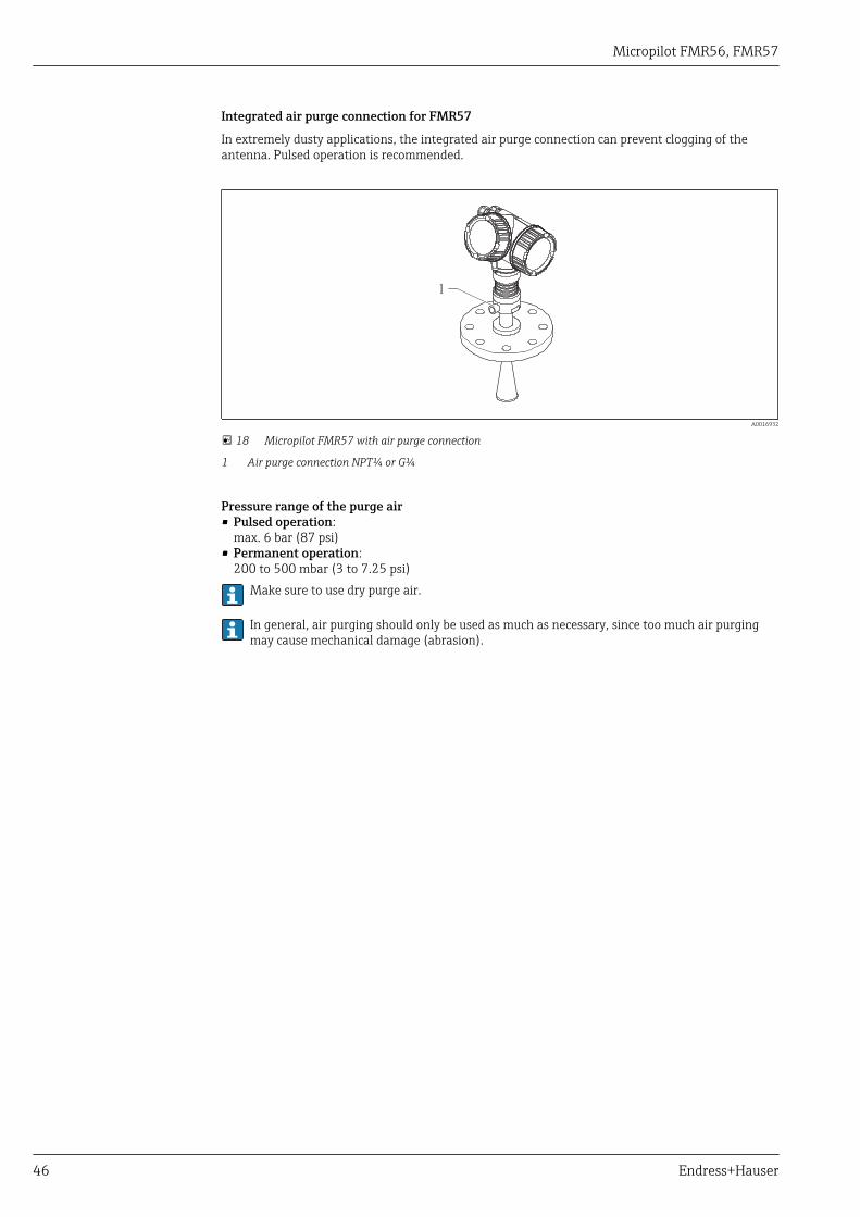
Integrated air purge connection for FMR57
In extremely dusty applications, the integrated air purge connection can prevent clogging of theantenna. Pulsed operation is recommended.
1
A0016932
18 Micropilot FMR57 with air purge connection
1 Air purge connection NPT¼ or G¼
Pressure range of the purge air• Pulsed operation:
max. 6 bar (87 psi)• Permanent operation:
200 to 500 mbar (3 to 7.25 psi)Make sure to use dry purge air.
In general, air purging should only be used as much as necessary, since too much air purgingmay cause mechanical damage (abrasion).
Micropilot FMR56, FMR57
Endress+Hauser 47
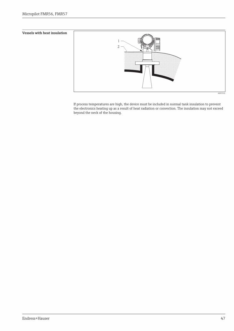
Vessels with heat insulation
1
2
A0019142
If process temperatures are high, the device must be included in normal tank insulation to preventthe electronics heating up as a result of heat radiation or convection. The insulation may not exceedbeyond the neck of the housing.
Micropilot FMR56, FMR57
48 Endress+Hauser
Environment
Ambient temperature range Measuring device –40 to +80 °C (–40 to +176 °F); –50 °C (–58 °F) with manufacturer declaration onrequest
Local display –20 to +70 °C (–4 to +158 °F), the readability of the display may be impaired attemperatures outside the temperature range.
When operating the device in the open with strong sunlight:• Mount the device in a shady position.• Avoid direct sunlight, especially in warmer regions.• Use a weather protection cover (see accessories).
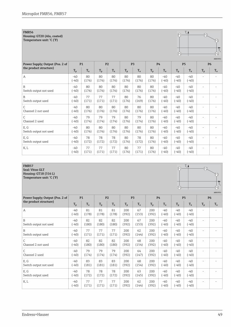
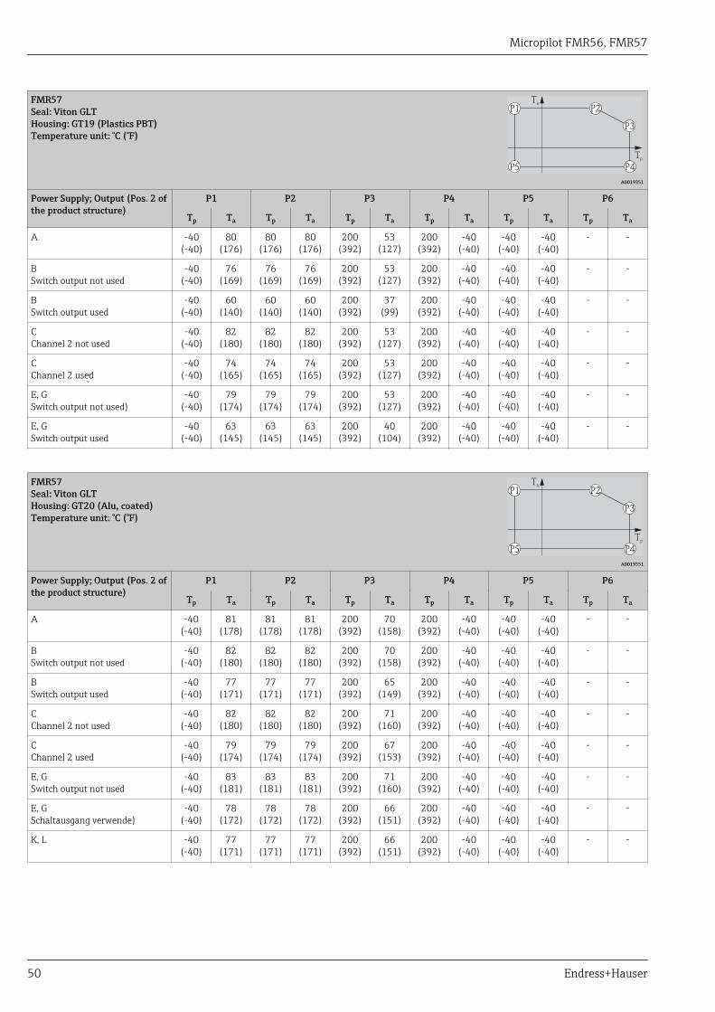
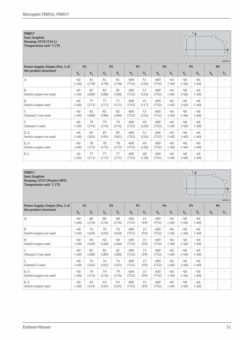
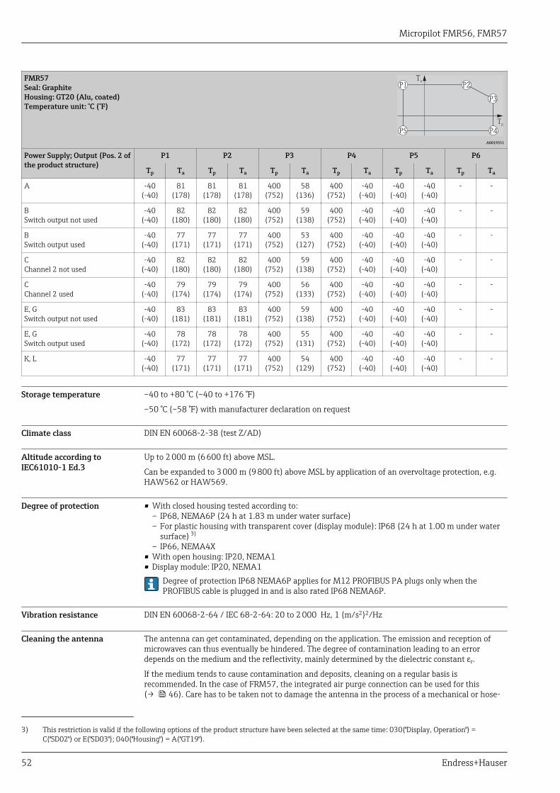
Ambient temperature limits The following diagrams take into account only functional aspects. There may be furtherrestrictions for certified device versions. Please refere to the separate Safety Instructions(→ 85).
With a temperature (Tp) at the process connection the admissible ambient temperature (Ta) isreduced according to the following diagram (temperature derating):
Information concerning the derating tables
Option Meaning
A 2-wire; 4-20 mA HART
B 2-wire; 4-20 mA HART, switch output
C 2-wire; 4-20 mA HART, 4-20 mA
E 2-wire; FF, switch output
G 2-wire; PA, switch output
K 4-wire 90-253VAC; 4-20 mA HART
L 4-wire 10, 4-48VDC; 4-20 mA HART
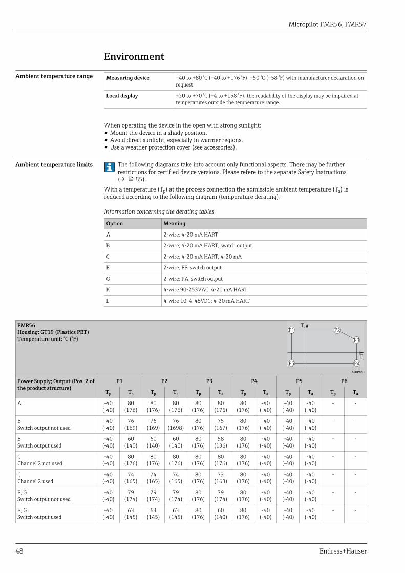
FMR56Housing: GT19 (Plastics PBT)Temperature unit: °C (°F)
Tp
P5 P4
P3
P2P1Ta
A0019351
Power Supply; Output (Pos. 2 ofthe product structure)
P1 P2 P3 P4 P5 P6
Tp Ta Tp Ta Tp Ta Tp Ta Tp Ta Tp Ta
A -40(-40)
80(176)
80(176)
80(176)
80(176)
80(176)
80(176)
-40(-40)
-40(-40)
-40(-40)
- -
BSwitch output not used
-40(-40)
76(169)
76(169)
76(1698)
80(176)
75(167)
80(176)
-40(-40)
-40(-40)
-40(-40)
- -
BSwitch output used
-40(-40)
60(140)
60(140)
60(140)
80(176)
58(136)
80(176)
-40(-40)
-40(-40)
-40(-40)
- -
CChannel 2 not used
-40(-40)
80(176)
80(176)
80(176)
80(176)
80(176)
80(176)
-40(-40)
-40(-40)
-40(-40)
- -
CChannel 2 used
-40(-40)
74(165)
74(165)
74(165)
80(176)
73(163)
80(176)
-40(-40)
-40(-40)
-40(-40)
- -
E, GSwitch output not used
-40(-40)
79(174)
79(174)
79(174)
80(176)
79(174)
80(176)
-40(-40)
-40(-40)
-40(-40)
- -
E, GSwitch output used
-40(-40)
63(145)
63(145)
63(145)
80(176)
60(140)
80(176)
-40(-40)
-40(-40)
-40(-40)
- -
Micropilot FMR56, FMR57
Endress+Hauser 49
FMR56Housing: GT20 (Alu, coated)Temperature unit: °C (°F)
Tp
P5 P4
P3
P2P1Ta
A0019351
Power Supply; Output (Pos. 2 ofthe product structure)
P1 P2 P3 P4 P5 P6
Tp Ta Tp Ta Tp Ta Tp Ta Tp Ta Tp Ta
A -40(-40)
80(176)
80(176)
80(176)
80(176)
80(176)
80(176)
-40(-40)
-40(-40)
-40(-40)
- -
BSwitch output not used
-40(-40)
80(176)
80(176)
80(176)
80(176)
80(176)
80(176)
-40(-40)
-40(-40)
-40(-40)
- -
BSwitch output used
-40(-40)
77(171)
77(171)
77(171)
80(176)
76(169)
80(176)
-40(-40)
-40(-40)
-40(-40)
- -
CChannel 2 not used
-40(-40)
80(176)
80(176)
80(176)
80(176)
80(176)
80(176)
-40(-40)
-40(-40)
-40(-40)
- -
CChannel 2 used
-40(-40)
79(174)
79(174)
79(174)
80(176)
79(174)
80(176)
-40(-40)
-40(-40)
-40(-40)
- -
E, GSwitch output not used
-40(-40)
80(176)
80(176)
80(176)
80(176)
80(176)
80(176)
-40(-40)
-40(-40)
-40(-40)
- -
E, GSwitch output used
-40(-40)
78(172)
78(172)
78(172)
80(176)
78(172)
80(176)
-40(-40)
-40(-40)
-40(-40)
- -
K, L -40(-40)
77(171)
77(171)
77(171)
80(176)
77(171)
80(176)
-40(-40)
-40(-40)
-40(-40)
- -
FMR57Seal: Viton GLTHousing: GT18 (316 L)Temperature unit: °C (°F)
Tp
P5 P4
P3
P2P1Ta
A0019351
Power Supply; Output (Pos. 2 ofthe product structure)
P1 P2 P3 P4 P5 P6
Tp Ta Tp Ta Tp Ta Tp Ta Tp Ta Tp Ta
A -40(-40)
81(178)
81(178)
81(178)
200(392)
67(153)
200(392)
-40(-40)
-40(-40)
-40(-40)
- -
BSwitch output not used
-40(-40)
82(180)
82(180)
82(180)
200(392)
67(153)
200(392)
-40(-40)
-40(-40)
-40(-40)
- -
BSwitch output used
-40(-40)
77(171)
77(171)
77(171)
200(392)
62(144)
200(392)
-40(-40)
-40(-40)
-40(-40)
- -
CChannel 2 not used
-40(-40)
82(180)
82(180)
82(180)
200(392)
68(154)
200(392)
-40(-40)
-40(-40)
-40(-40)
- -
CChannel 2 used
-40(-40)
79(174)
79(174)
79(174)
200(392)
64(147)
200(392)
-40(-40)
-40(-40)
-40(-40)
- -
E, GSwitch output not used
-40(-40)
83(181)
83(181)
83(181)
200(392)
68(154)
200(392)
-40(-40)
-40(-40)
-40(-40)
- -
E, GSwitch output used
-40(-40)
78(172)
78(172)
78(172)
200(392)
63(145)
200(392)
-40(-40)
-40(-40)
-40(-40)
- -
K, L -40(-40)
77(171)
77(171)
77(171)
200(392)
62(144)
200(392)
-40(-40)
-40(-40)
-40(-40)
- -
Micropilot FMR56, FMR57
50 Endress+Hauser
FMR57Seal: Viton GLTHousing: GT19 (Plastics PBT)Temperature unit: °C (°F)
Tp
P5 P4
P3
P2P1Ta
A0019351
Power Supply; Output (Pos. 2 ofthe product structure)
P1 P2 P3 P4 P5 P6
Tp Ta Tp Ta Tp Ta Tp Ta Tp Ta Tp Ta
A -40(-40)
80(176)
80(176)
80(176)
200(392)
53(127)
200(392)
-40(-40)
-40(-40)
-40(-40)
- -
BSwitch output not used
-40(-40)
76(169)
76(169)
76(169)
200(392)
53(127)
200(392)
-40(-40)
-40(-40)
-40(-40)
- -
BSwitch output used
-40(-40)
60(140)
60(140)
60(140)
200(392)
37(99)
200(392)
-40(-40)
-40(-40)
-40(-40)
- -
CChannel 2 not used
-40(-40)
82(180)
82(180)
82(180)
200(392)
53(127)
200(392)
-40(-40)
-40(-40)
-40(-40)
- -
CChannel 2 used
-40(-40)
74(165)
74(165)
74(165)
200(392)
53(127)
200(392)
-40(-40)
-40(-40)
-40(-40)
- -
E, GSwitch output not used)
-40(-40)
79(174)
79(174)
79(174)
200(392)
53(127)
200(392)
-40(-40)
-40(-40)
-40(-40)
- -
E, GSwitch output used
-40(-40)
63(145)
63(145)
63(145)
200(392)
40(104)
200(392)
-40(-40)
-40(-40)
-40(-40)
- -
FMR57Seal: Viton GLTHousing: GT20 (Alu, coated)Temperature unit: °C (°F)
Tp
P5 P4
P3
P2P1Ta
A0019351
Power Supply; Output (Pos. 2 ofthe product structure)
P1 P2 P3 P4 P5 P6
Tp Ta Tp Ta Tp Ta Tp Ta Tp Ta Tp Ta
A -40(-40)
81(178)
81(178)
81(178)
200(392)
70(158)
200(392)
-40(-40)
-40(-40)
-40(-40)
- -
BSwitch output not used
-40(-40)
82(180)
82(180)
82(180)
200(392)
70(158)
200(392)
-40(-40)
-40(-40)
-40(-40)
- -
BSwitch output used
-40(-40)
77(171)
77(171)
77(171)
200(392)
65(149)
200(392)
-40(-40)
-40(-40)
-40(-40)
- -
CChannel 2 not used
-40(-40)
82(180)
82(180)
82(180)
200(392)
71(160)
200(392)
-40(-40)
-40(-40)
-40(-40)
- -
CChannel 2 used
-40(-40)
79(174)
79(174)
79(174)
200(392)
67(153)
200(392)
-40(-40)
-40(-40)
-40(-40)
- -
E, GSwitch output not used
-40(-40)
83(181)
83(181)
83(181)
200(392)
71(160)
200(392)
-40(-40)
-40(-40)
-40(-40)
- -
E, GSchaltausgang verwende)
-40(-40)
78(172)
78(172)
78(172)
200(392)
66(151)
200(392)
-40(-40)
-40(-40)
-40(-40)
- -
K, L -40(-40)
77(171)
77(171)
77(171)
200(392)
66(151)
200(392)
-40(-40)
-40(-40)
-40(-40)
- -
Micropilot FMR56, FMR57
Endress+Hauser 51
FMR57Seal: GraphiteHousing: GT18 (316 L)Temperature unit: °C (°F)
Tp
P5 P4
P3
P2P1Ta
A0019351
Power Supply; Output (Pos. 2 ofthe product structure)
P1 P2 P3 P4 P5 P6
Tp Ta Tp Ta Tp Ta Tp Ta Tp Ta Tp Ta
A -40(-40)
81(178)
81(178)
81(178)
400(752)
51(124)
400(752)
-40(-40)
-40(-40)
-40(-40)
- -
BSwitch output not used
-40(-40)
82(180)
82(180)
82(180)
400(752)
51(124)
400(752)
-40(-40)
-40(-40)
-40(-40)
- -
BSwitch output used
-40(-40)
77(171)
77(171)
77(171)
400(752)
47(117)
400(752)
-40(-40)
-40(-40)
-40(-40)
- -
CChannel 2 not used
-40(-40)
82(180)
82(180)
82(180)
400(752)
51(124)
400(752)
-40(-40)
-40(-40)
-40(-40)
- -
CChannel 2 used
-40(-40)
79(174)
79(174)
79(174)
400(752)
49(120)
400(752)
-40(-40)
-40(-40)
-40(-40)
- -
E, GSwitch output not used
-40(-40)
83(181)
83(181)
83(181)
400(752)
51(124)
400(752)
-40(-40)
-40(-40)
-40(-40)
- -
E, GSwitch output used
-40(-40)
78(172)
78(172)
78(172)
400(752)
49(120)
400(752)
-40(-40)
-40(-40)
-40(-40)
- -
K, L -40(-40)
77(171)
77(171)
77(171)
400(752)
48(118)
400(752)
-40(-40)
-40(-40)
-40(-40)
- -
FMR57Seal: GraphiteHousing: GT19 (Plastics PBT)Temperature unit: °C (°F)
Tp
P5 P4
P3
P2P1Ta
A0019351
Power Supply; Output (Pos. 2 ofthe product structure)
P1 P2 P3 P4 P5 P6
Tp Ta Tp Ta Tp Ta Tp Ta Tp Ta Tp Ta
A -40(-40)
80(176)
80(176)
80(176)
400(752)
15(59)
400(752)
-40(-40)
-40(-40)
-40(-40)
- -
BSwitch output not used
-40(-40)
76(169)
76(169)
76(169)
400(752)
15(59)
400(752)
-40(-40)
-40(-40)
-40(-40)
- -
BSwitch output used
-40(-40)
60(140)
60(140)
60(140)
400(752)
15(59)
400(752)
-40(-40)
-40(-40)
-40(-40)
- -
CChannel 2 not used
-40(-40)
82(180)
82(180)
82(180)
400(752)
15(59)
400(752)
-40(-40)
-40(-40)
-40(-40)
- -
CChannel 2 used
-40(-40)
74(165)
74(165)
74(165)
400(752)
15(59)
400(752)
-40(-40)
-40(-40)
-40(-40)
- -
E, GSwitch output not used
-40(-40)
79(174)
79(174)
79(174)
400(752)
15(59)
400(752)
-40(-40)
-40(-40)
-40(-40)
- -
E, GSwitch output used
-40(-40)
63(145)
63(145)
63(145)
400(752)
15(59)
400(752)
-40(-40)
-40(-40)
-40(-40)
- -
Micropilot FMR56, FMR57
52 Endress+Hauser
FMR57Seal: GraphiteHousing: GT20 (Alu, coated)Temperature unit: °C (°F)
Tp
P5 P4
P3
P2P1Ta
A0019351
Power Supply; Output (Pos. 2 ofthe product structure)
P1 P2 P3 P4 P5 P6
Tp Ta Tp Ta Tp Ta Tp Ta Tp Ta Tp Ta
A -40(-40)
81(178)
81(178)
81(178)
400(752)
58(136)
400(752)
-40(-40)
-40(-40)
-40(-40)
- -
BSwitch output not used
-40(-40)
82(180)
82(180)
82(180)
400(752)
59(138)
400(752)
-40(-40)
-40(-40)
-40(-40)
- -
BSwitch output used
-40(-40)
77(171)
77(171)
77(171)
400(752)
53(127)
400(752)
-40(-40)
-40(-40)
-40(-40)
- -
CChannel 2 not used
-40(-40)
82(180)
82(180)
82(180)
400(752)
59(138)
400(752)
-40(-40)
-40(-40)
-40(-40)
- -
CChannel 2 used
-40(-40)
79(174)
79(174)
79(174)
400(752)
56(133)
400(752)
-40(-40)
-40(-40)
-40(-40)
- -
E, GSwitch output not used
-40(-40)
83(181)
83(181)
83(181)
400(752)
59(138)
400(752)
-40(-40)
-40(-40)
-40(-40)
- -
E, GSwitch output used
-40(-40)
78(172)
78(172)
78(172)
400(752)
55(131)
400(752)
-40(-40)
-40(-40)
-40(-40)
- -
K, L -40(-40)
77(171)
77(171)
77(171)
400(752)
54(129)
400(752)
-40(-40)
-40(-40)
-40(-40)
- -
Storage temperature –40 to +80 °C (–40 to +176 °F)
–50 °C (–58 °F) with manufacturer declaration on request
Climate class DIN EN 60068-2-38 (test Z/AD)
Altitude according toIEC61010-1 Ed.3
Up to 2 000 m (6 600 ft) above MSL.
Can be expanded to 3 000 m (9 800 ft) above MSL by application of an overvoltage protection, e.g.HAW562 or HAW569.
Degree of protection • With closed housing tested according to:– IP68, NEMA6P (24 h at 1.83 m under water surface)– For plastic housing with transparent cover (display module): IP68 (24 h at 1.00 m under water
surface) 3)
– IP66, NEMA4X• With open housing: IP20, NEMA1• Display module: IP20, NEMA1
Degree of protection IP68 NEMA6P applies for M12 PROFIBUS PA plugs only when thePROFIBUS cable is plugged in and is also rated IP68 NEMA6P.
Vibration resistance DIN EN 60068-2-64 / IEC 68-2-64: 20 to 2 000 Hz, 1 (m/s2)2/Hz
Cleaning the antenna The antenna can get contaminated, depending on the application. The emission and reception ofmicrowaves can thus eventually be hindered. The degree of contamination leading to an errordepends on the medium and the reflectivity, mainly determined by the dielectric constant εr.
If the medium tends to cause contamination and deposits, cleaning on a regular basis isrecommended. In the case of FRM57, the integrated air purge connection can be used for this(→ 46). Care has to be taken not to damage the antenna in the process of a mechanical or hose-
3) This restriction is valid if the following options of the product structure have been selected at the same time: 030("Display, Operation") =C("SD02") or E("SD03"); 040("Housing") = A("GT19").
Micropilot FMR56, FMR57
Endress+Hauser 53
down cleaning. The material compatibility has to be considered if cleaning agents are used! Themaximum permitted temperature at the flange should not be exceeded.
Air purge connection
in preparation
Electromagneticcompatibility (EMC)
Electromagnetic compatibility to all relevant requirements of the EN 61326- series and NAMURrecommendation EMC (NE21). For details see declaration of conformity. 4).
If only the analogue signal is used, unshielded interconnection lines are sufficient for theinstallation. In case of using the digital signal (HART/ PA/ FF) use shielded interconnection lines.
Max. fluctuations during EMC- tests: < 0.5 % of the span. As an exception to this, the maximumfluctuations may amount to 2 % of the span for devices with plastic housing and see-through lid(integrated display SD02 or SD03) if strong electromagnetic interferences in the frequenency rangeof 1 to 2 GHz are present.
4) Can be downloaded from www.endress.com.
Micropilot FMR56, FMR57
54 Endress+Hauser
Process
Process temperature range Sensor Seal Process temperature range
FMR56 - –40 to +80 °C (–40 to +176 °F)
FMR57 Viton GLT –40 to +200 °C (–40 to +392 °F)
Graphite –40 to +400 °C (–40 to +752 °F)
Process pressure range Sensor Process pressure range
FMR56 prel = –1 to 3 bar (–14.5 to 43.5 psi)pabs < 4 bar (58 psi)
FMR57 prel = –1 to 16 bar (–14.5 to 232 psi)
This range may be reduced by the selected process connection. The pressure rating (PN)specified on the flanges refers to a reference temperature of 20 °C, for ASME flanges 100 °F.Pay attention to pressure-temperature dependencies.
Please refer to the following standards for the pressure values permitted for highertemperatures:• EN 1092-1: 2001 Tab. 18
With regard to their temperature stability properties, the materials 1.4435 and 1.4404 aregrouped under 13E0 in EN 1092-1 Tab. 18. The chemical composition of the two materialscan be identical.
• ASME B 16.5a - 1998 Tab. 2-2.2 F316• ASME B 16.5a - 1998 Tab. 2.3.8 N10276• JIS B 2220
Dielectric constant • For liquids– εr≥1.9 in free-field applications– εr≥1.4 in stilling well
• For bulk solidsεr≥1.6
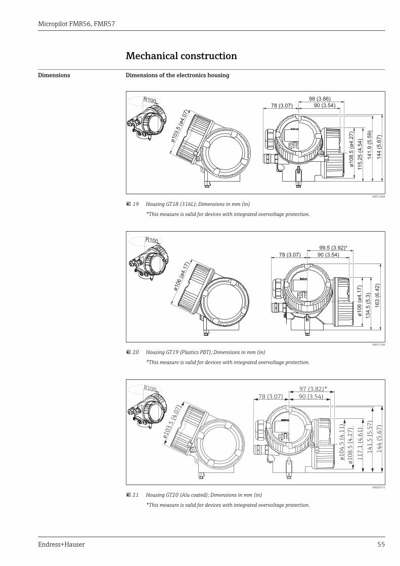
Micropilot FMR56, FMR57
Endress+Hauser 55
Mechanical construction
Dimensions Dimensions of the electronics housing
144 (
5.6
7)
141.9
(5.5
9)
115.2
5 (
4.5
4)
ø108.5
(ø
4.2
7)
78 (3.07) 90 (3.54)
98 (3.86)
ø103.5
(ø4.0
7)
R100
A0011666
19 Housing GT18 (316L); Dimensions in mm (in)
*This measure is valid for devices with integrated overvoltage protection.
163 (
6.4
2)
134.5
(5.3
)
ø106 (
ø4.1
7)
78 (3.07) 90 (3.54)
99.5 (3.92)*
ø106 (ø4.1
7)
R100
A0011346
20 Housing GT19 (Plastics PBT); Dimensions in mm (in)
*This measure is valid for devices with integrated overvoltage protection.
14
4 (
5.6
7)
14
1.5
(5
.57
)
11
7.1
(4
.61
)
ø1
04
.5 (
4.1
1)
ø1
08
.5 (
4.2
7)
78 (3.07) 90 (3.54)
97 (3.82)*
ø10
3.5
(4
.07
)
R100
A0020751
21 Housing GT20 (Alu coated); Dimensions in mm (in)
*This measure is valid for devices with integrated overvoltage protection.
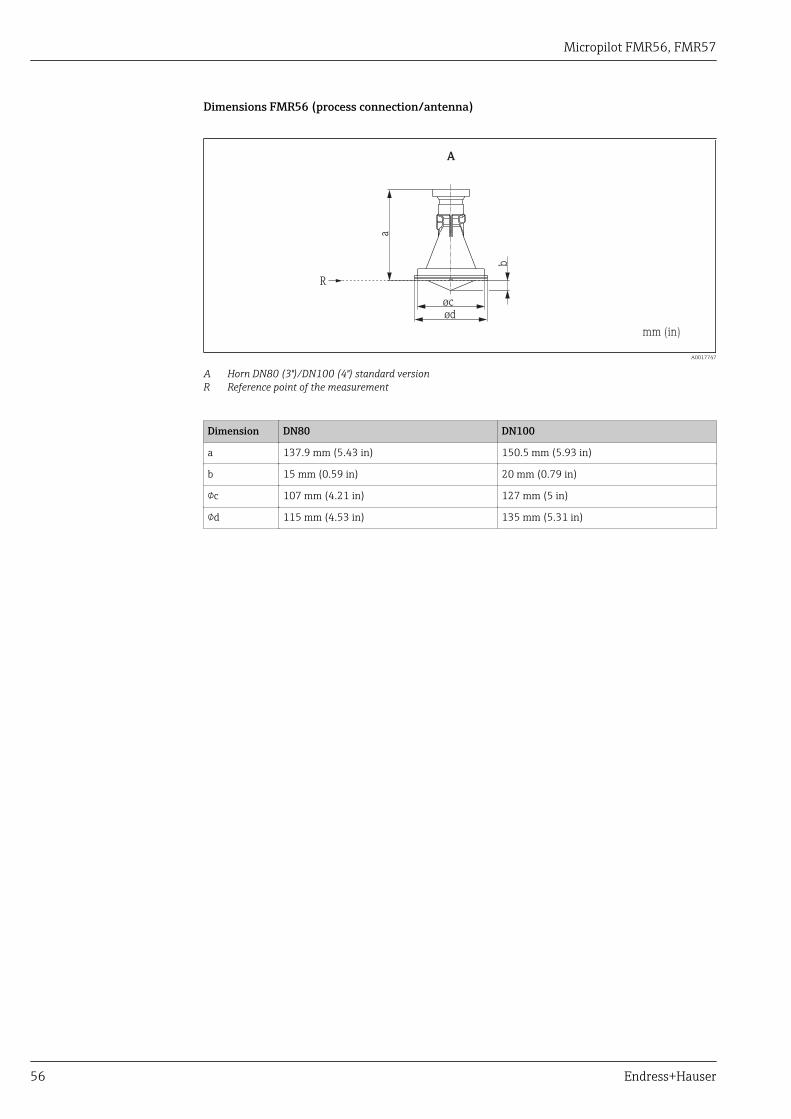
Micropilot FMR56, FMR57
56 Endress+Hauser
Dimensions FMR56 (process connection/antenna)
R
A
ød
mm (in)
øc
b
a
A0017747
A Horn DN80 (3")/DN100 (4") standard versionR Reference point of the measurement
Dimension DN80 DN100
a 137.9 mm (5.43 in) 150.5 mm (5.93 in)
b 15 mm (0.59 in) 20 mm (0.79 in)
c 107 mm (4.21 in) 127 mm (5 in)
d 115 mm (4.53 in) 135 mm (5.31 in)
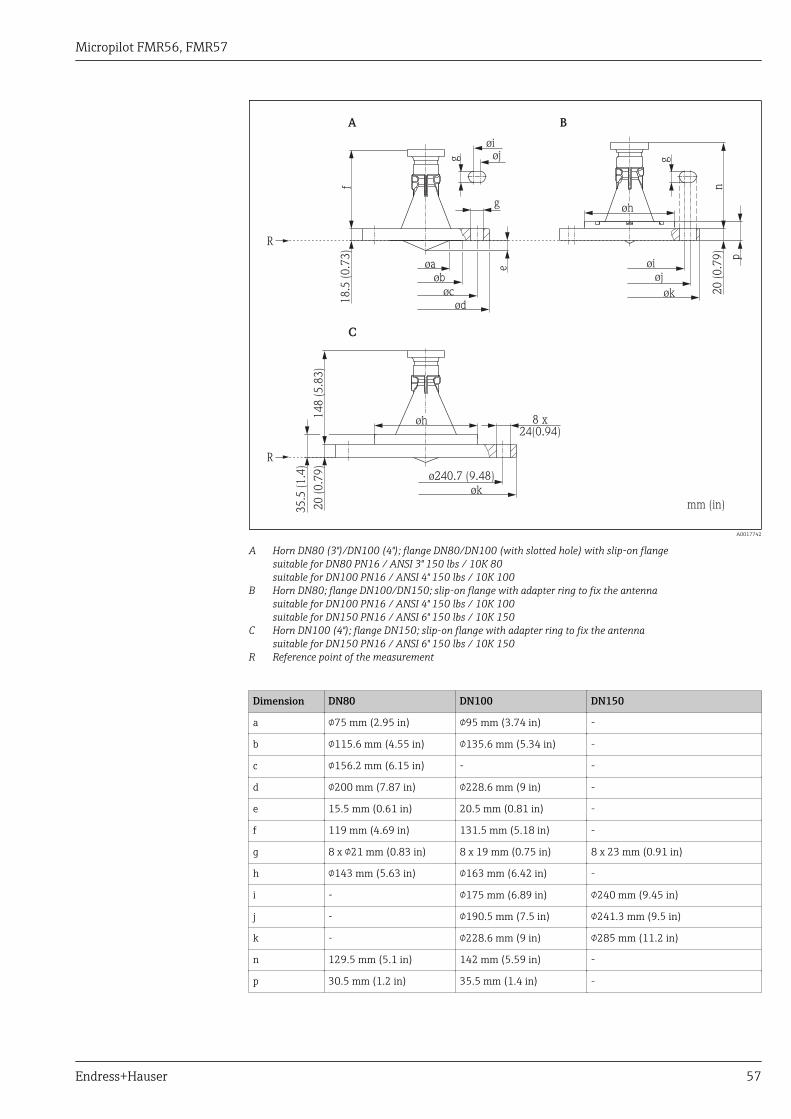
Micropilot FMR56, FMR57
Endress+Hauser 57
R
øa øi
øi
øj
øj
øk
g
8 x24(0.94)
øb
øc
ø240.7 (9.48)
ød
øk
R
C
A B
f
148 (
5.8
3)
n
18.5
(0.7
3)
20 (
0.7
9)
35.5
(1.4
)
20 (
0.7
9)
e
øh
øh
mm (in)
p
gg
A0017742
A Horn DN80 (3")/DN100 (4"); flange DN80/DN100 (with slotted hole) with slip-on flangesuitable for DN80 PN16 / ANSI 3" 150 lbs / 10K 80suitable for DN100 PN16 / ANSI 4" 150 lbs / 10K 100
B Horn DN80; flange DN100/DN150; slip-on flange with adapter ring to fix the antennasuitable for DN100 PN16 / ANSI 4" 150 lbs / 10K 100suitable for DN150 PN16 / ANSI 6" 150 lbs / 10K 150
C Horn DN100 (4"); flange DN150; slip-on flange with adapter ring to fix the antennasuitable for DN150 PN16 / ANSI 6" 150 lbs / 10K 150
R Reference point of the measurement
Dimension DN80 DN100 DN150
a 75 mm (2.95 in) 95 mm (3.74 in) -
b 115.6 mm (4.55 in) 135.6 mm (5.34 in) -
c 156.2 mm (6.15 in) - -
d 200 mm (7.87 in) 228.6 mm (9 in) -
e 15.5 mm (0.61 in) 20.5 mm (0.81 in) -
f 119 mm (4.69 in) 131.5 mm (5.18 in) -
g 8 x 21 mm (0.83 in) 8 x 19 mm (0.75 in) 8 x 23 mm (0.91 in)
h 143 mm (5.63 in) 163 mm (6.42 in) -
i - 175 mm (6.89 in) 240 mm (9.45 in)
j - 190.5 mm (7.5 in) 241.3 mm (9.5 in)
k - 228.6 mm (9 in) 285 mm (11.2 in)
n 129.5 mm (5.1 in) 142 mm (5.59 in) -
p 30.5 mm (1.2 in) 35.5 mm (1.4 in) -
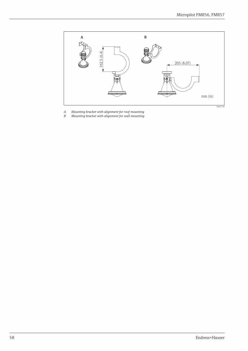
Micropilot FMR56, FMR57
58 Endress+Hauser
mm (in)
A B
162.5
(6.4
)
205 (8.07)
A0017746
A Mounting bracket with alignment for roof mountingB Mounting bracket with alignment for wall mounting
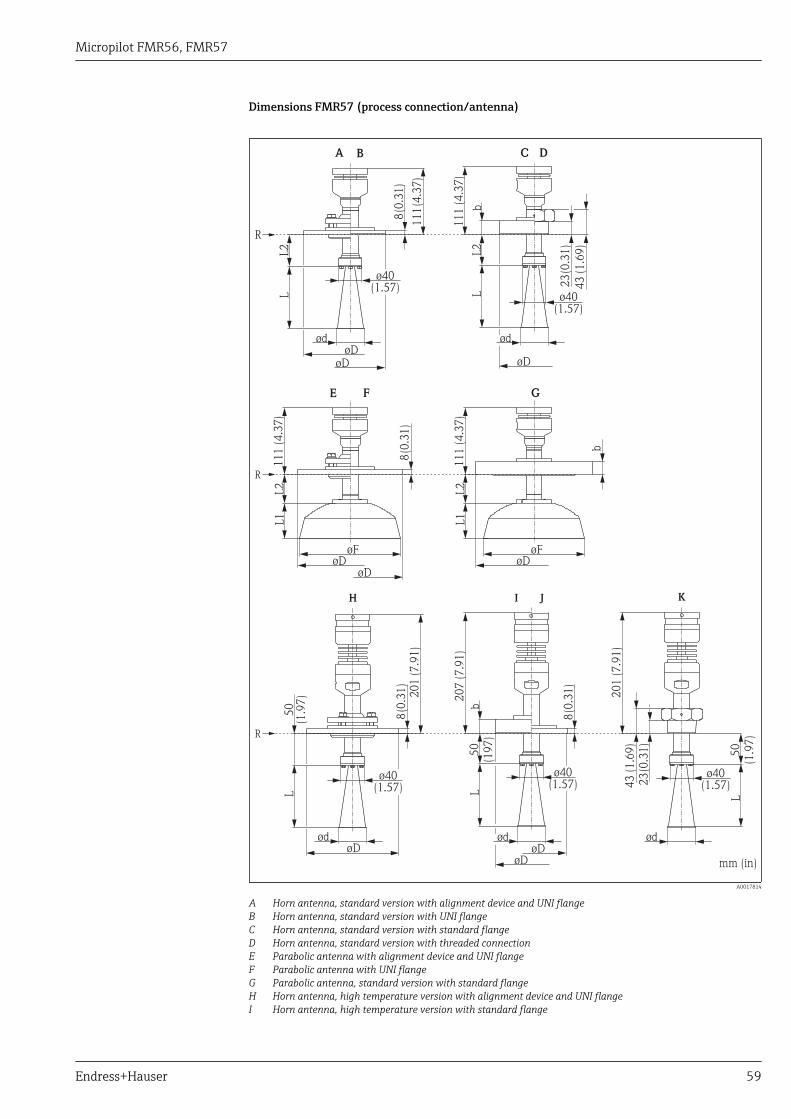
Micropilot FMR56, FMR57
Endress+Hauser 59
Dimensions FMR57 (process connection/antenna)
R
R
A
H
CB
I J
D
K
E F G
R
øDøD
øD
øD
øD mm (in)
øF øF
øDøD øD
øD
ød
ød
LL
LL
L
L1
L1
L2
L2
L2
50
(1.9
7) 2
01 (
7.9
1)
111
(4.3
7)
8(0
.31)
8(0
.31)
8(0
.31)
b
8(0
.31)
23
(0.3
1)
23
(0.3
1)
ø40(1.57)
ød
ød ød
L2
50
(197)
50
(1.9
7)
bb
111 (
4.3
7)
207 (
7.9
1)
43 (
1.6
9)
43 (
1.6
9)
201 (
7.9
1)
111 (
4.3
7)
111 (
4.3
7)
ø40(1.57)
ø40(1.57)
ø40(1.57)
ø40(1.57)
A0017814
A Horn antenna, standard version with alignment device and UNI flangeB Horn antenna, standard version with UNI flangeC Horn antenna, standard version with standard flangeD Horn antenna, standard version with threaded connectionE Parabolic antenna with alignment device and UNI flangeF Parabolic antenna with UNI flangeG Parabolic antenna, standard version with standard flangeH Horn antenna, high temperature version with alignment device and UNI flangeI Horn antenna, high temperature version with standard flange
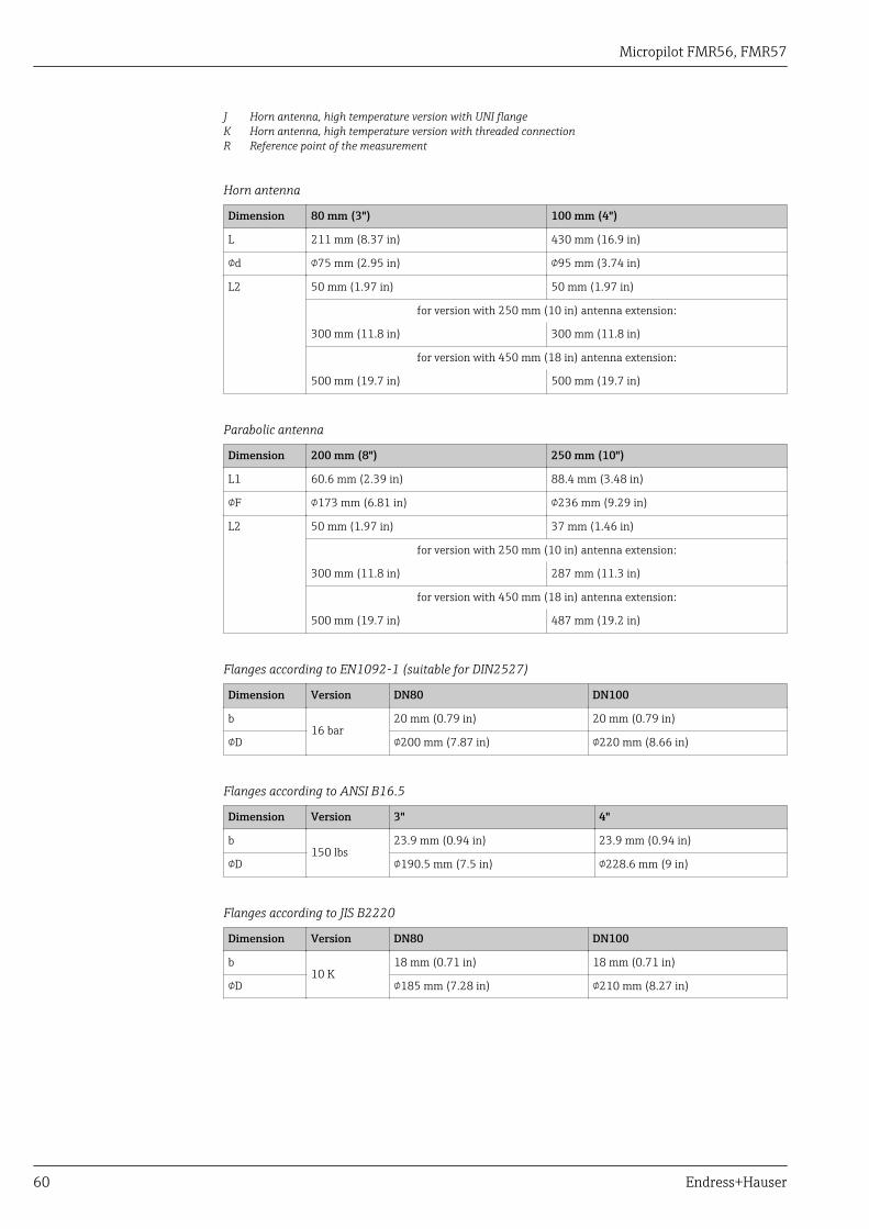
Micropilot FMR56, FMR57
60 Endress+Hauser
J Horn antenna, high temperature version with UNI flangeK Horn antenna, high temperature version with threaded connectionR Reference point of the measurement
Horn antenna
Dimension 80 mm (3") 100 mm (4")
L 211 mm (8.37 in) 430 mm (16.9 in)
d 75 mm (2.95 in) 95 mm (3.74 in)
L2 50 mm (1.97 in) 50 mm (1.97 in)
for version with 250 mm (10 in) antenna extension:
300 mm (11.8 in) 300 mm (11.8 in)
for version with 450 mm (18 in) antenna extension:
500 mm (19.7 in) 500 mm (19.7 in)
Parabolic antenna
Dimension 200 mm (8") 250 mm (10")
L1 60.6 mm (2.39 in) 88.4 mm (3.48 in)
F 173 mm (6.81 in) 236 mm (9.29 in)
L2 50 mm (1.97 in) 37 mm (1.46 in)
for version with 250 mm (10 in) antenna extension:
300 mm (11.8 in) 287 mm (11.3 in)
for version with 450 mm (18 in) antenna extension:
500 mm (19.7 in) 487 mm (19.2 in)
Flanges according to EN1092-1 (suitable for DIN2527)
Dimension Version DN80 DN100
b16 bar
20 mm (0.79 in) 20 mm (0.79 in)
D 200 mm (7.87 in) 220 mm (8.66 in)
Flanges according to ANSI B16.5
Dimension Version 3" 4"
b150 lbs
23.9 mm (0.94 in) 23.9 mm (0.94 in)
D 190.5 mm (7.5 in) 228.6 mm (9 in)
Flanges according to JIS B2220
Dimension Version DN80 DN100
b10 K
18 mm (0.71 in) 18 mm (0.71 in)
D 185 mm (7.28 in) 210 mm (8.27 in)
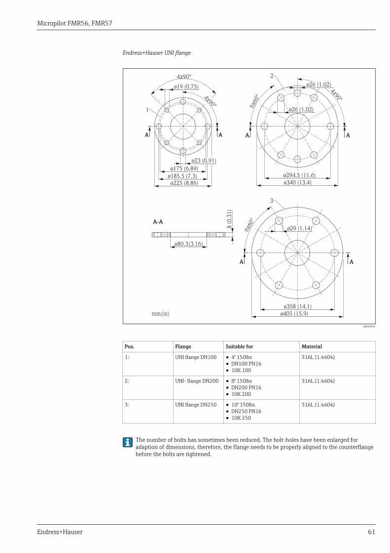
Micropilot FMR56, FMR57
Endress+Hauser 61
Endress+Hauser UNI flange
A
A
A
A
A-A
8 (
0.3
1)
ø340 (13.4)
ø405 (15.9)
4x90°
6x60
°
6x60
°
ø26 (1.02)
ø26 (1.02)
ø29 (1.14)
ø358 (14.1)
ø294.5 (11.6)
ø80.3(3.16)
mm(in)
2
3
ø175 (6.89)
4x90°
4x90°
ø225 (8.86)
ø19 (0.75)
A A
ø185.5 (7.3)
1
ø23 (0.91)
A0018947
Pos. Flange Suitable for Material
1: UNI flange DN100 • 4" 150lbs• DN100 PN16• 10K 100
316L (1.4404)
2: UNI- flange DN200 • 8" 150lbs• DN200 PN16• 10K 200
316L (1.4404)
3: UNI flange DN250 • 10" 150lbs• DN250 PN16• 10K 250
316L (1.4404)
The number of bolts has sometimes been reduced. The bolt-holes have been enlarged foradaption of dimensions, therefore, the flange needs to be properly aligned to the counterflangebefore the bolts are tightened.
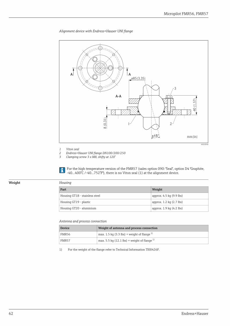
Micropilot FMR56, FMR57
62 Endress+Hauser
Alignment device with Endress+Hauser UNI flange
A
A-A
A
8 (
0.3
1)
40 (
1.5
7)
ø85(3.35)
mm(in)
3
1
±15°
2
A0018948
1 Viton seal2 Endress+Hauser UNI flange DN100/200/2503 Clamping screw 3 x M8, shifty at 120°
For the high temperature version of the FMR57 (sales option 090: "Seal", option D4 "Graphite,-40...400°C /-40...752°F"), there is no Viton seal (1) at the alignment device.
Weight Housing
Part Weight
Housing GT18 - stainless steel approx. 4.5 kg (9.9 lbs)
Housing GT19 - plastic approx. 1.2 kg (2.7 lbs)
Housing GT20 - aluminium approx. 1.9 kg (4.2 lbs)
Antenna and process connection
Device Weight of antenna and process connection
FMR56 max. 1.5 kg (3.3 lbs) + weight of flange 1)
FMR57 max. 5.5 kg (12.1 lbs) + weight of flange 1)
1) For the weight of the flange refer to Technical Information TI00426F.
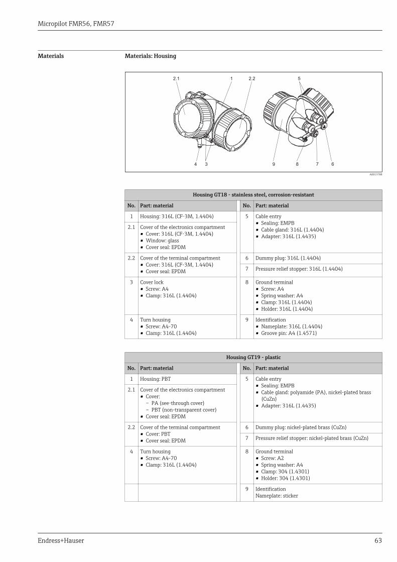
Micropilot FMR56, FMR57
Endress+Hauser 63
Materials Materials: Housing
2.1 1 2.2 5
678934
A0013788
Housing GT18 - stainless steel, corrosion-resistant
No. Part: material No. Part: material
1 Housing: 316L (CF-3M, 1.4404) 5 Cable entry• Sealing: EMPB• Cable gland: 316L (1.4404)• Adapter: 316L (1.4435)
2.1 Cover of the electronics compartment• Cover: 316L (CF-3M, 1.4404)• Window: glass• Cover seal: EPDM
2.2 Cover of the terminal compartment• Cover: 316L (CF-3M, 1.4404)• Cover seal: EPDM
6 Dummy plug: 316L (1.4404)
7 Pressure relief stopper: 316L (1.4404)
3 Cover lock• Screw: A4• Clamp: 316L (1.4404)
8 Ground terminal• Screw: A4• Spring washer: A4• Clamp: 316L (1.4404)• Holder: 316L (1.4404)
4 Turn housing• Screw: A4-70• Clamp: 316L (1.4404)
9 Identification• Nameplate: 316L (1.4404)• Groove pin: A4 (1.4571)
Housing GT19 - plastic
No. Part: material No. Part: material
1 Housing: PBT 5 Cable entry• Sealing: EMPB• Cable gland: polyamide (PA), nickel-plated brass
(CuZn)• Adapter: 316L (1.4435)
2.1 Cover of the electronics compartment• Cover:
– PA (see-through cover)– PBT (non-transparent cover)
• Cover seal: EPDM
2.2 Cover of the terminal compartment• Cover: PBT• Cover seal: EPDM
6 Dummy plug: nickel-plated brass (CuZn)
7 Pressure relief stopper: nickel-plated brass (CuZn)
4 Turn housing• Screw: A4-70• Clamp: 316L (1.4404)
8 Ground terminal• Screw: A2• Spring washer: A4• Clamp: 304 (1.4301)• Holder: 304 (1.4301)
9 IdentificationNameplate: sticker
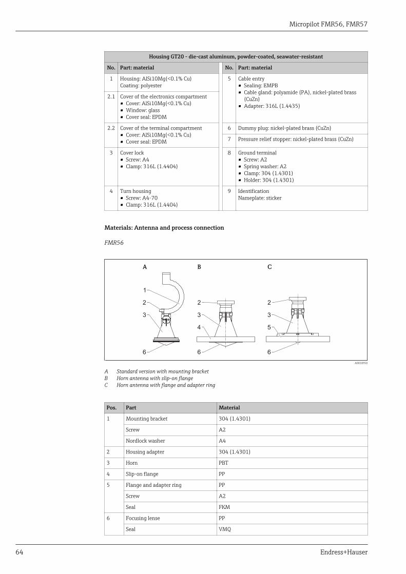
Micropilot FMR56, FMR57
64 Endress+Hauser
Housing GT20 - die-cast aluminum, powder-coated, seawater-resistant
No. Part: material No. Part: material
1 Housing: AlSi10Mg(<0.1% Cu)Coating: polyester
5 Cable entry• Sealing: EMPB• Cable gland: polyamide (PA), nickel-plated brass
(CuZn)• Adapter: 316L (1.4435)
2.1 Cover of the electronics compartment• Cover: AlSi10Mg(<0.1% Cu)• Window: glass• Cover seal: EPDM
2.2 Cover of the terminal compartment• Cover: AlSi10Mg(<0.1% Cu)• Cover seal: EPDM
6 Dummy plug: nickel-plated brass (CuZn)
7 Pressure relief stopper: nickel-plated brass (CuZn)
3 Cover lock• Screw: A4• Clamp: 316L (1.4404)
8 Ground terminal• Screw: A2• Spring washer: A2• Clamp: 304 (1.4301)• Holder: 304 (1.4301)
4 Turn housing• Screw: A4-70• Clamp: 316L (1.4404)
9 IdentificationNameplate: sticker
Materials: Antenna and process connection
FMR56
A B C
1
2
3
6 6 6
3
4
3
5
2 2
A0018950
A Standard version with mounting bracketB Horn antenna with slip-on flangeC Horn antenna with flange and adapter ring
Pos. Part Material
1 Mounting bracket 304 (1.4301)
Screw A2
Nordlock washer A4
2 Housing adapter 304 (1.4301)
3 Horn PBT
4 Slip-on flange PP
5 Flange and adapter ring PP
Screw A2
Seal FKM
6 Focusing lense PP
Seal VMQ
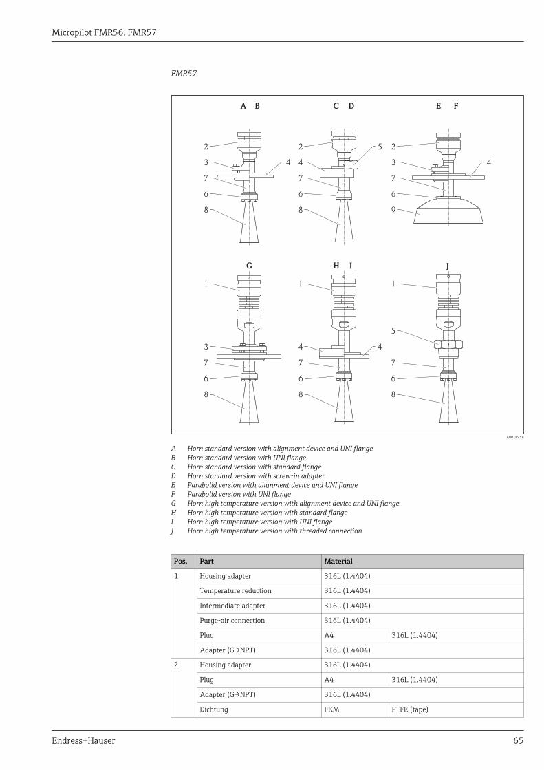
Micropilot FMR56, FMR57
Endress+Hauser 65
FMR57
A
G H I J
CB D E F
3 3
3
2 2 2
1 1 1
5
44 4
44
5
7
7 7 7
7 7
6
6 6 6
6 6
8
8 8 8
8 9
A0018958
A Horn standard version with alignment device and UNI flangeB Horn standard version with UNI flangeC Horn standard version with standard flangeD Horn standard version with screw-in adapterE Parabolid version with alignment device and UNI flangeF Parabolid version with UNI flangeG Horn high temperature version with alignment device and UNI flangeH Horn high temperature version with standard flangeI Horn high temperature version with UNI flangeJ Horn high temperature version with threaded connection
Pos. Part Material
1 Housing adapter 316L (1.4404)
Temperature reduction 316L (1.4404)
Intermediate adapter 316L (1.4404)
Purge-air connection 316L (1.4404)
Plug A4 316L (1.4404)
Adapter (G→NPT) 316L (1.4404)
2 Housing adapter 316L (1.4404)
Plug A4 316L (1.4404)
Adapter (G→NPT) 316L (1.4404)
Dichtung FKM PTFE (tape)
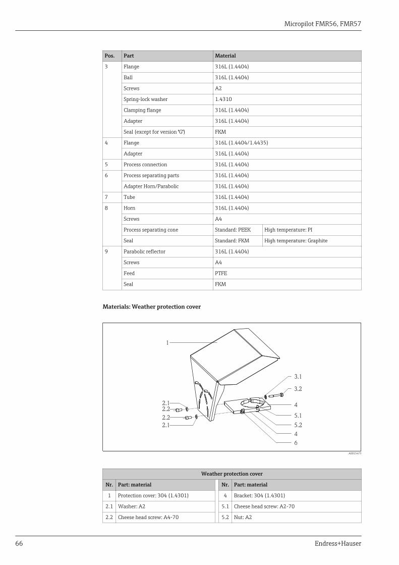
Micropilot FMR56, FMR57
66 Endress+Hauser
Pos. Part Material
3 Flange 316L (1.4404)
Ball 316L (1.4404)
Screws A2
Spring-lock washer 1.4310
Clamping flange 316L (1.4404)
Adapter 316L (1.4404)
Seal (except for version "G") FKM
4 Flange 316L (1.4404/1.4435)
Adapter 316L (1.4404)
5 Process connection 316L (1.4404)
6 Process separating parts 316L (1.4404)
Adapter Horn/Parabolic 316L (1.4404)
7 Tube 316L (1.4404)
8 Horn 316L (1.4404)
Screws A4
Process separating cone Standard: PEEK High temperature: PI
Seal Standard: FKM High temperature: Graphite
9 Parabolic reflector 316L (1.4404)
Screws A4
Feed PTFE
Seal FKM
Materials: Weather protection cover
1
2.1
3.1
3.2
4
5.1
5.2
4
6
2.2
2.2
2.1
A0015473
Weather protection cover
Nr. Part: material Nr. Part: material
1 Protection cover: 304 (1.4301) 4 Bracket: 304 (1.4301)
2.1 Washer: A2 5.1 Cheese head screw: A2-70
2.2 Cheese head screw: A4-70 5.2 Nut: A2

Micropilot FMR56, FMR57
Endress+Hauser 67
Weather protection cover
Nr. Part: material Nr. Part: material
3.1 Washer: A2 6 Ground terminal• Screw: A4• Spring washer: A4• Clamp: 316L (1.4404)• Holder: 316L (1.4404)
3.2 Tightening screw: 304 (1.4301)
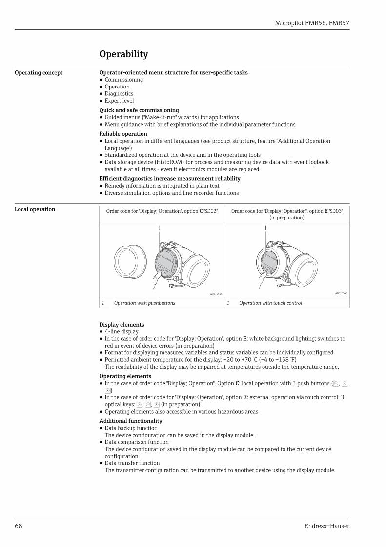
Micropilot FMR56, FMR57
68 Endress+Hauser
Operability
Operating concept Operator-oriented menu structure for user-specific tasks• Commissioning• Operation• Diagnostics• Expert levelQuick and safe commissioning• Guided menus ("Make-it-run" wizards) for applications• Menu guidance with brief explanations of the individual parameter functionsReliable operation• Local operation in different languages (see product structure, feature "Additional Operation
Language")• Standardized operation at the device and in the operating tools• Data storage device (HistoROM) for process and measuring device data with event logbook
available at all times - even if electronics modules are replacedEfficient diagnostics increase measurement reliability• Remedy information is integrated in plain text• Diverse simulation options and line recorder functions
Local operation Order code for "Display; Operation", option C "SD02" Order code for "Display; Operation", option E "SD03"(in preparation)
+
E
–
1
A0015544
1
+
E
–
A0015546
1 Operation with pushbuttons 1 Operation with touch control
Display elements• 4-line display• In the case of order code for "Display; Operation", option E: white background lighting; switches to
red in event of device errors (in preparation)• Format for displaying measured variables and status variables can be individually configured• Permitted ambient temperature for the display: –20 to +70 °C (–4 to +158 °F)
The readability of the display may be impaired at temperatures outside the temperature range.Operating elements• In the case of order code "Display; Operation", Option C: local operation with 3 push buttons ( , ,
E )• In the case of order code for "Display; Operation", option E: external operation via touch control; 3
optical keys: , , E (in preparation)• Operating elements also accessible in various hazardous areasAdditional functionality• Data backup function
The device configuration can be saved in the display module.• Data comparison function
The device configuration saved in the display module can be compared to the current deviceconfiguration.
• Data transfer functionThe transmitter configuration can be transmitted to another device using the display module.
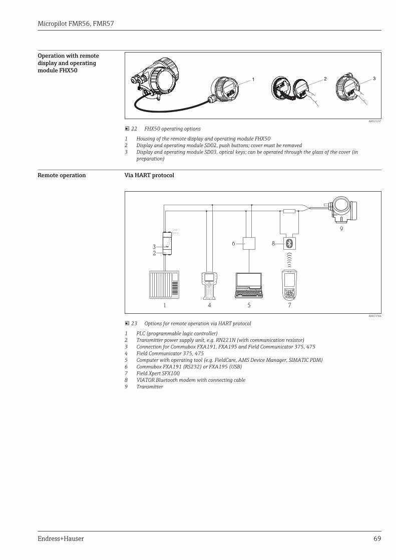
Micropilot FMR56, FMR57
Endress+Hauser 69
Operation with remotedisplay and operatingmodule FHX50
321
A0013137
22 FHX50 operating options
1 Housing of the remote display and operating module FHX502 Display and operating module SD02, push buttons; cover must be removed3 Display and operating module SD03, optical keys; can be operated through the glass of the cover (in
preparation)
Remote operation Via HART protocol
1
2
4 5 7
9
6 83
A0013764
23 Options for remote operation via HART protocol
1 PLC (programmable logic controller)2 Transmitter power supply unit, e.g. RN221N (with communication resistor)3 Connection for Commubox FXA191, FXA195 and Field Communicator 375, 4754 Field Communicator 375, 4755 Computer with operating tool (e.g. FieldCare, AMS Device Manager, SIMATIC PDM)6 Commubox FXA191 (RS232) or FXA195 (USB)7 Field Xpert SFX1008 VIATOR Bluetooth modem with connecting cable9 Transmitter
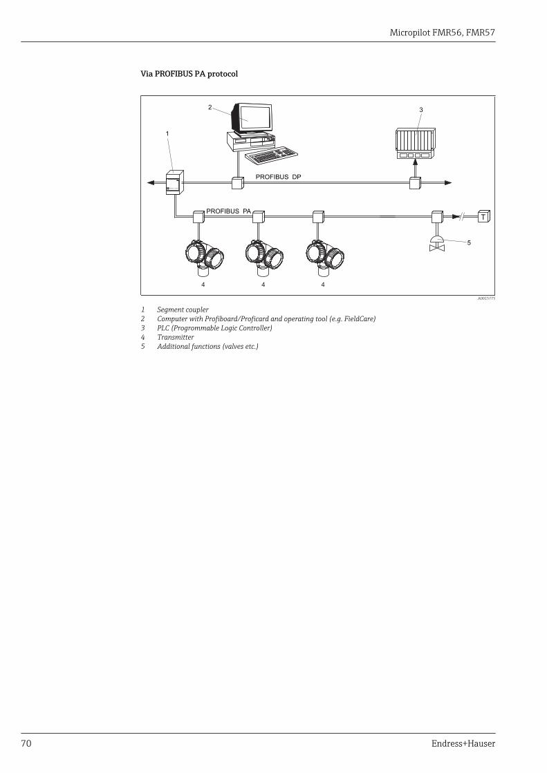
Micropilot FMR56, FMR57
70 Endress+Hauser
Via PROFIBUS PA protocol
ENDRESS + HAUSER
T
PROFIBUS DP
PROFIBUS PA
1
23
5
4 4 4
A0015775
1 Segment coupler2 Computer with Profiboard/Proficard and operating tool (e.g. FieldCare)3 PLC (Progrommable Logic Controller)4 Transmitter5 Additional functions (valves etc.)
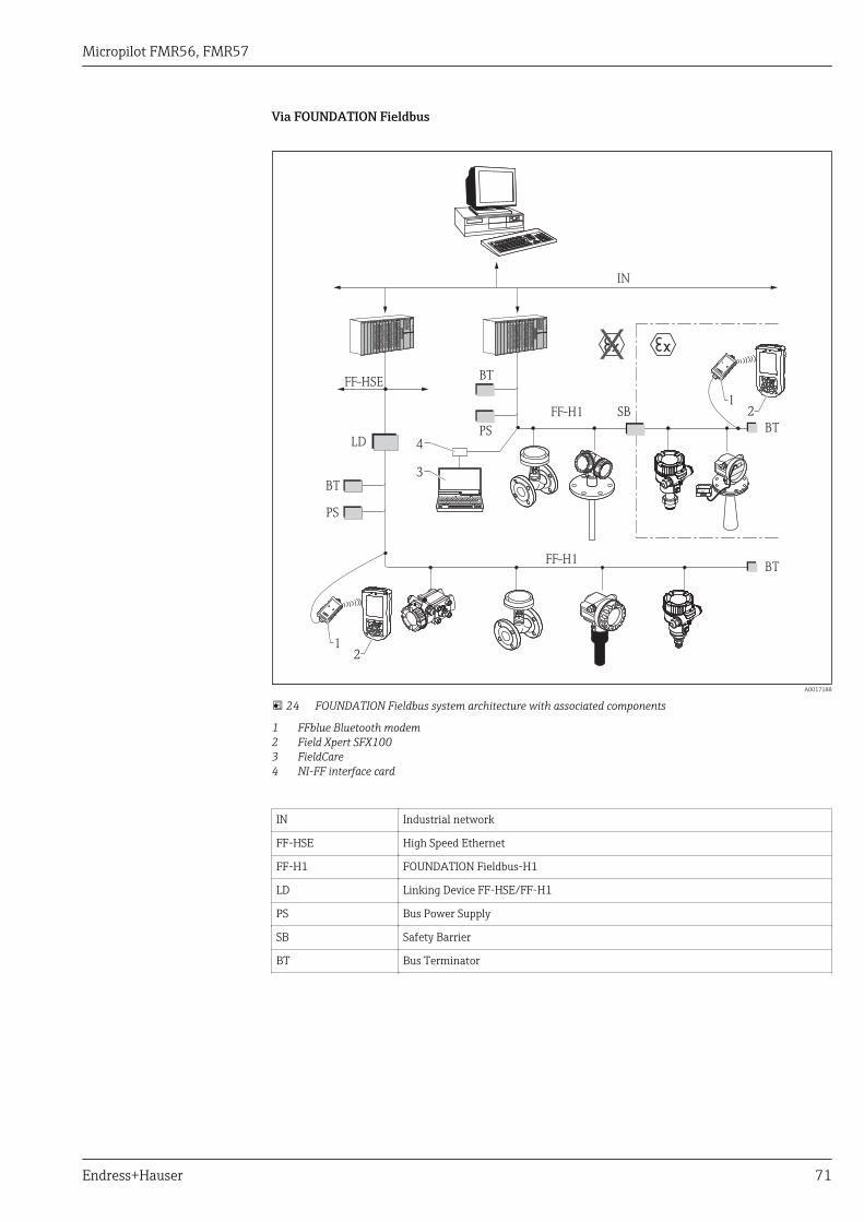
Micropilot FMR56, FMR57
Endress+Hauser 71
Via FOUNDATION Fieldbus
FF-H1
FF-H1
BT
BT
PS
3
4
PS
BT
SB
BT
FF-HSE
IN
LD
ENDRESS + HAUSER
E+–
%
1
1
2
2
A0017188
24 FOUNDATION Fieldbus system architecture with associated components
1 FFblue Bluetooth modem2 Field Xpert SFX1003 FieldCare4 NI-FF interface card
IN Industrial network
FF-HSE High Speed Ethernet
FF-H1 FOUNDATION Fieldbus-H1
LD Linking Device FF-HSE/FF-H1
PS Bus Power Supply
SB Safety Barrier
BT Bus Terminator
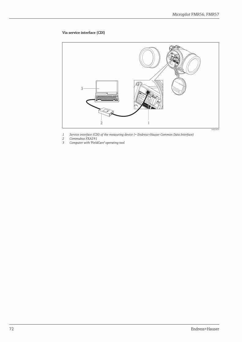
Micropilot FMR56, FMR57
72 Endress+Hauser
Via service interface (CDI)
+
E
–
12
3
A0014019
1 Service interface (CDI) of the measuring device (= Endress+Hauser Common Data Interface)2 Commubox FXA2913 Computer with "FieldCare" operating tool
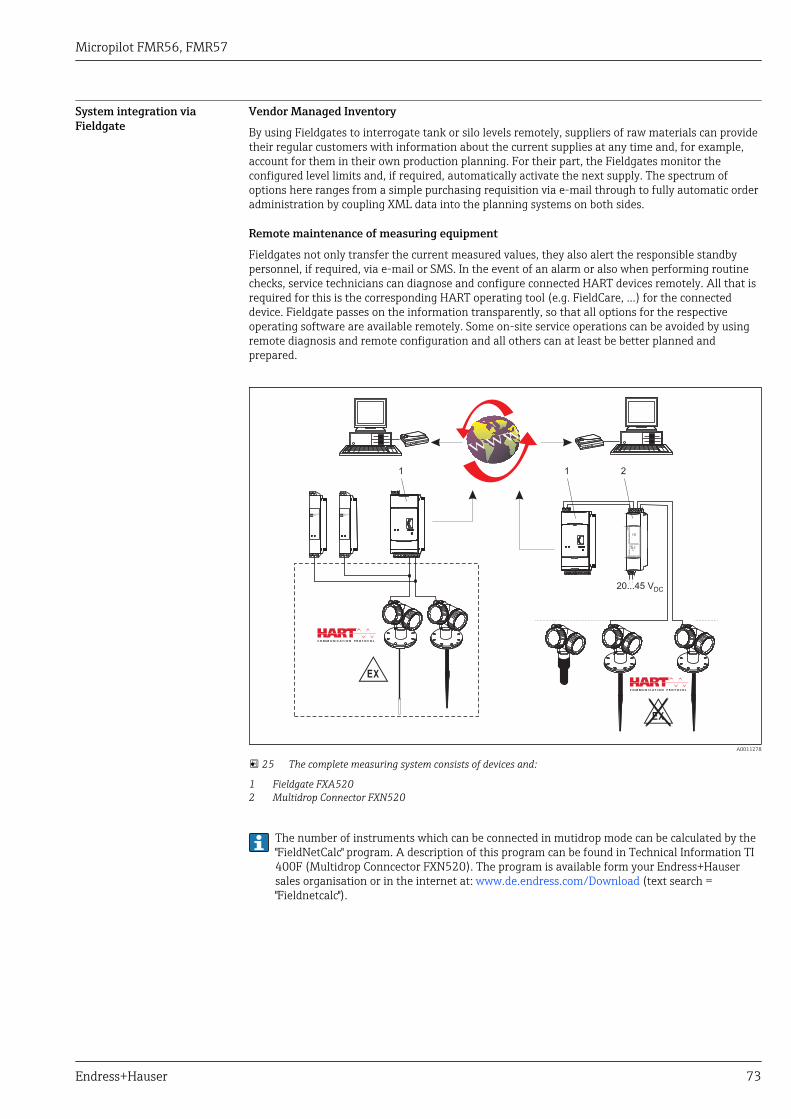
Micropilot FMR56, FMR57
Endress+Hauser 73
System integration viaFieldgate
Vendor Managed Inventory
By using Fieldgates to interrogate tank or silo levels remotely, suppliers of raw materials can providetheir regular customers with information about the current supplies at any time and, for example,account for them in their own production planning. For their part, the Fieldgates monitor theconfigured level limits and, if required, automatically activate the next supply. The spectrum ofoptions here ranges from a simple purchasing requisition via e-mail through to fully automatic orderadministration by coupling XML data into the planning systems on both sides.
Remote maintenance of measuring equipment
Fieldgates not only transfer the current measured values, they also alert the responsible standbypersonnel, if required, via e-mail or SMS. In the event of an alarm or also when performing routinechecks, service technicians can diagnose and configure connected HART devices remotely. All that isrequired for this is the corresponding HART operating tool (e.g. FieldCare, ...) for the connecteddevice. Fieldgate passes on the information transparently, so that all options for the respectiveoperating software are available remotely. Some on-site service operations can be avoided by usingremote diagnosis and remote configuration and all others can at least be better planned andprepared.
-
ENDRESS+HAUSER
RN 221N
ENDRESS+HAUSER
RN 221N
.
20...45 VDC
FX
N 5
20
FX
N 5
20
1 1 2
A0011278
25 The complete measuring system consists of devices and:
1 Fieldgate FXA5202 Multidrop Connector FXN520
The number of instruments which can be connected in mutidrop mode can be calculated by the"FieldNetCalc" program. A description of this program can be found in Technical Information TI400F (Multidrop Conncector FXN520). The program is available form your Endress+Hausersales organisation or in the internet at: www.de.endress.com/Download (text search ="Fieldnetcalc").
Micropilot FMR56, FMR57
74 Endress+Hauser
Certificates and approvals
CE mark The measuring system meets the legal requirements of the applicable EC guidelines. These are listedin the corresponding EC Declaration of Conformity together with the standards applied.
Endress+Hauser confirms successful testing of the device by affixing to it the CE mark.
C-Tick symbol The measuring system meets the EMC requirements of the "Australian Communications and MediaAuthority (ACMA)".
Ex approval • ATEX• IEC Ex• CSA (in Vorbereitung)• FM (in Vorbereitung)• NEPSI (in Vorbereitung)• TIIS (in Vorbereitung)Additional safety instructions must be observed for applications in hazardous areas. They arecontained in the separate "Safety Instructions" (XA) document, which is included in the scope ofdelivery. Reference is made to the XA on the nameplate of the device.
Details on the available certificats as well as the associated XAs can be found in the Associateddocumentation chapter in the Safety instructions section: (→ 85).
Dual seal according toANSI/ISA 12.27.01
The devices Micropilot FMR5x have been designed according to ANSI/ISA 12.27.01 as dual sealdevices, allowing the user to waive the use and save the cost of installing external secondary processseals in the conduit as required by the process sealing sections of ANSI/NFPA 70 (NEC) and CSA22.1 (CEC). These instruments comply with the North-American installation practice and provide avery safe and cost-saving installation for pressurized applications with hazardous fluids.
Further information can be found in the control drawings of the relevant devices.
Functional Safety Used for level monitoring (MIN, MAX, range) up to SIL 3 (homogeneous or inhomogeneousredundancy), independently assessed by TÜV Rhineland as per IEC 61508. Other information seedocumentation SD01087F: "Functional Safety Manual".
WHG in preparation
AD2000 The pressure retaining material 316L (1.4435/1.4404) corresponds to AD2000 - W2/W10.
Pressure EquipmentDirective
The Micropilot is not subject to the scope of the Pressure Equipment Directive 97/23/EC, as it doesnot have a pressure-bearing housing according to article 1, section 2.1.4 of the directive.
Marine certificate (inpreparation)
in preparation
Radio standardEN302729-1/2
The devices Micropilot FMR50, FMR51, FMR52, FMR56 and FMR57 are conform with the LPR(Level Probing Radar) standard EN302729-1/2. The devices are allowed to be used inside or outsideof closed bins or tanks in countries of th EU and the EFTA. Precondition is that the country itselfalready has implemented the directive.
At present, the following countries have already implemented the directive:
Belgium, Bulgaria, Germany, Denmark, Estonia, France, Greece, Great Britain, Ireland, Iceland, Italy,Liechtenstein, Lithuania, Latvia, Malta, Netherland, Norway, Austria, Poland, Romania, Sweden,Switzerland, Slovakia, Spain, Czech Republic and Cyprus.
All countries not mentioned above are at present in the implementation phase.
For the use of the devices outside of closed bins or tanks, the following has to be observed:1. The installation has to be done by trained personnel.2. The antenna of the device has to be mounted on a fixed place and vertically to the bottom.3. The mounting place has to be in a distance of at least 4 km to the mentioned astronomical
stations or an appropriate permission has to be issued by the national authority. If the device is
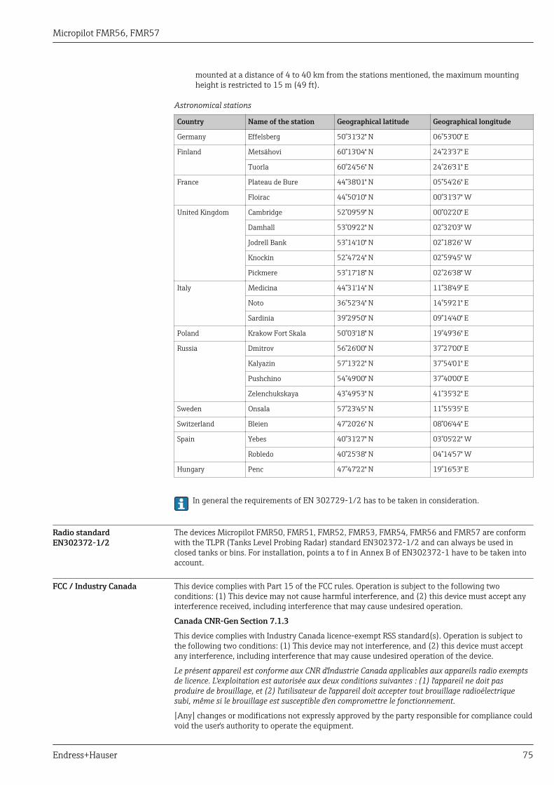
Micropilot FMR56, FMR57
Endress+Hauser 75
mounted at a distance of 4 to 40 km from the stations mentioned, the maximum mountingheight is restricted to 15 m (49 ft).
Astronomical stations
Country Name of the station Geographical latitude Geographical longitude
Germany Effelsberg 50°31'32" N 06°53'00" E
Finland Metsähovi 60°13'04" N 24°23'37" E
Tuorla 60°24'56" N 24°26'31" E
France Plateau de Bure 44°38'01" N 05°54'26" E
Floirac 44°50'10" N 00°31'37" W
United Kingdom Cambridge 52°09'59" N 00°02'20" E
Damhall 53°09'22" N 02°32'03" W
Jodrell Bank 53°14'10" N 02°18'26" W
Knockin 52°47'24" N 02°59'45" W
Pickmere 53°17'18" N 02°26'38" W
Italy Medicina 44°31'14" N 11°38'49" E
Noto 36°52'34" N 14°59'21" E
Sardinia 39°29'50" N 09°14'40" E
Poland Krakow Fort Skala 50°03'18" N 19°49'36" E
Russia Dmitrov 56°26'00" N 37°27'00" E
Kalyazin 57°13'22" N 37°54'01" E
Pushchino 54°49'00" N 37°40'00" E
Zelenchukskaya 43°49'53" N 41°35'32" E
Sweden Onsala 57°23'45" N 11°55'35" E
Switzerland Bleien 47°20'26" N 08°06'44" E
Spain Yebes 40°31'27" N 03°05'22" W
Robledo 40°25'38" N 04°14'57" W
Hungary Penc 47°47'22" N 19°16'53" E
In general the requirements of EN 302729-1/2 has to be taken in consideration.
Radio standardEN302372-1/2
The devices Micropilot FMR50, FMR51, FMR52, FMR53, FMR54, FMR56 and FMR57 are conformwith the TLPR (Tanks Level Probing Radar) standard EN302372-1/2 and can always be used inclosed tanks or bins. For installation, points a to f in Annex B of EN302372-1 have to be taken intoaccount.
FCC / Industry Canada This device complies with Part 15 of the FCC rules. Operation is subject to the following twoconditions: (1) This device may not cause harmful interference, and (2) this device must accept anyinterference received, including interference that may cause undesired operation.
Canada CNR-Gen Section 7.1.3
This device complies with Industry Canada licence-exempt RSS standard(s). Operation is subject tothe following two conditions: (1) This device may not interference, and (2) this device must acceptany interference, including interference that may cause undesired operation of the device.
Le présent appareil est conforme aux CNR d'Industrie Canada applicables aux appareils radio exemptsde licence. L'exploitation est autorisée aux deux conditions suivantes : (1) l'appareil ne doit pasproduire de brouillage, et (2) l'utilisateur de l'appareil doit accepter tout brouillage radioélectriquesubi, même si le brouillage est susceptible d'en compromettre le fonctionnement.
[Any] changes or modifications not expressly approved by the party responsible for compliance couldvoid the user's authority to operate the equipment.
Micropilot FMR56, FMR57
76 Endress+Hauser
Japanes radio approval The devices FMR50, FMR51, FMR52, FMR54 and FMR57 comply with the Japanese Radio Law,Article 6, Section 1(1).
CRN approval in preparation
Track record FMR5x is the upgrade model of the corresponding FMR2xx series.
Other standards andguidelines
• EN 60529Degrees of protection by housing (IP code)
• EN 61010-1Protection Measures for Electrical Equipment for Measurement, Control, Regulation andLaboratory Procedures.
• IEC/EN 61326"Emission in accordance with Class A requirements". Electromagnetic compatibility (EMCrequirements)
• NAMUR NE 21Electromagnetic compatibility (EMC) of industrial process and laboratory control equipment.
• NAMUR NE 43Standardization of the signal level for the breakdown information of digital transmitters withanalog output signal.
• NAMUR NE 53Software of field devices and signal-processing devices with digital electronics
• NAMUR NE 107Status classification as per NE107
• NAMUR NE 131Requirements for field devices for standard applications
• IEC61508Functional safety of electrical/electronic/programmable electronic safety-related systems
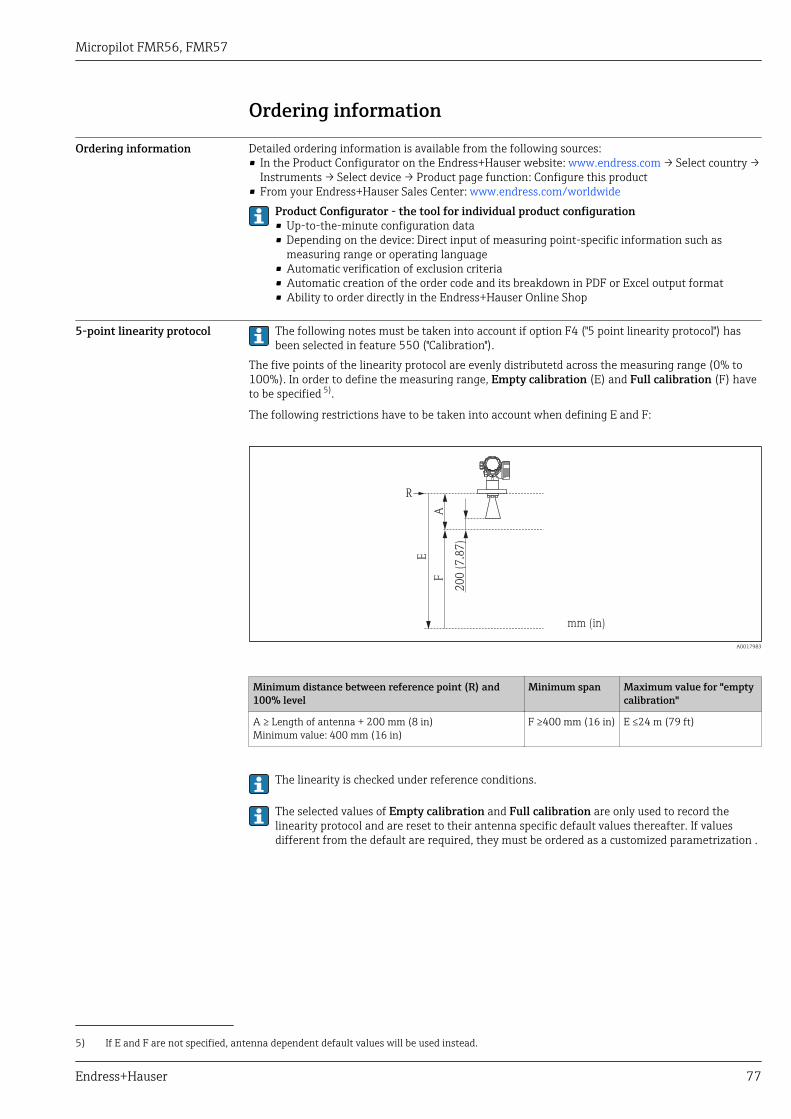
Micropilot FMR56, FMR57
Endress+Hauser 77
Ordering information
Ordering information Detailed ordering information is available from the following sources:• In the Product Configurator on the Endress+Hauser website: www.endress.com → Select country →
Instruments → Select device → Product page function: Configure this product• From your Endress+Hauser Sales Center: www.endress.com/worldwide
Product Configurator - the tool for individual product configuration• Up-to-the-minute configuration data• Depending on the device: Direct input of measuring point-specific information such as
measuring range or operating language• Automatic verification of exclusion criteria• Automatic creation of the order code and its breakdown in PDF or Excel output format• Ability to order directly in the Endress+Hauser Online Shop
5-point linearity protocol The following notes must be taken into account if option F4 ("5 point linearity protocol") hasbeen selected in feature 550 ("Calibration").
The five points of the linearity protocol are evenly distributetd across the measuring range (0% to100%). In order to define the measuring range, Empty calibration (E) and Full calibration (F) haveto be specified 5).
The following restrictions have to be taken into account when defining E and F:
R
AF
200 (
7.8
7)
mm (in)
E
A0017983
Minimum distance between reference point (R) and100% level
Minimum span Maximum value for "emptycalibration"
A ≥ Length of antenna + 200 mm (8 in)Minimum value: 400 mm (16 in)
F ≥400 mm (16 in) E ≤24 m (79 ft)
The linearity is checked under reference conditions.
The selected values of Empty calibration and Full calibration are only used to record thelinearity protocol and are reset to their antenna specific default values thereafter. If valuesdifferent from the default are required, they must be ordered as a customized parametrization .
5) If E and F are not specified, antenna dependent default values will be used instead.
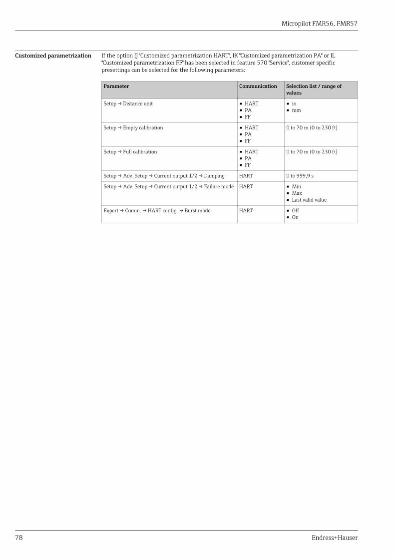
Micropilot FMR56, FMR57
78 Endress+Hauser
Customized parametrization If the option IJ "Customized parametrization HART", IK "Customized parametrization PA" or IL"Customized parametrization FF" has been selected in feature 570 "Service", customer specificpresettings can be selected for the following parameters:
Parameter Communication Selection list / range ofvalues
Setup → Distance unit • HART• PA• FF
• in• mm
Setup → Empty calibration • HART• PA• FF
0 to 70 m (0 to 230 ft)
Setup → Full calibration • HART• PA• FF
0 to 70 m (0 to 230 ft)
Setup → Adv. Setup → Current output 1/2 → Damping HART 0 to 999,9 s
Setup → Adv. Setup → Current output 1/2 → Failure mode HART • Min• Max• Last valid value
Expert → Comm. → HART config. → Burst mode HART • Off• On
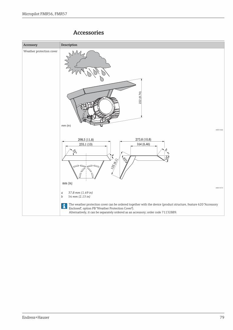
Micropilot FMR56, FMR57
Endress+Hauser 79
Accessories
Device-specific accessoriesAccessory Description
Weather protection cover
222 (
8.7
4)
mm (in)
A0015466
55°
35°
b
164 (6.46)
273.8 (10.8)
155 (6.1
)
65°
255.1 (10)
mm (in)
298.5 (11.8)
a
A0015472
a 37.8 mm (1.49 in)b 54 mm (2.13 in)
The weather protection cover can be ordered together with the device (product structure, feature 620 "AccessoryEnclosed", option PB "Weather Protection Cover").Alternatively, it can be separately ordered as an accessory; order code 71132889.
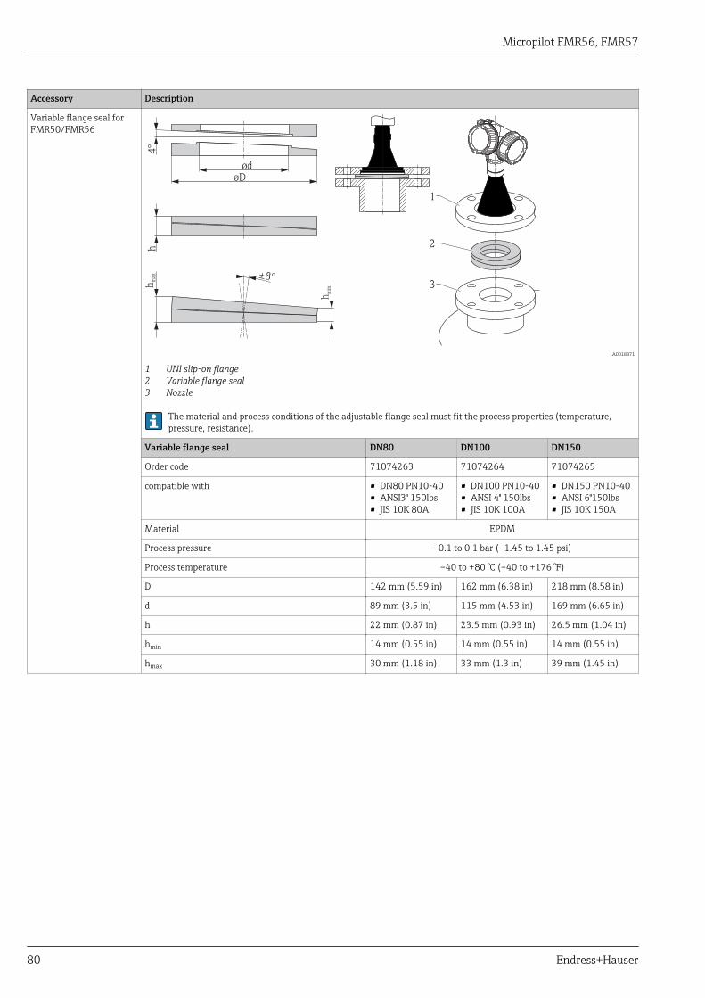
Micropilot FMR56, FMR57
80 Endress+Hauser
Accessory Description
Variable flange seal forFMR50/FMR56
h
2
3
1
4°
øD
ød
hm
ax
hm
in
±8°
A0018871
1 UNI slip-on flange2 Variable flange seal3 Nozzle
The material and process conditions of the adjustable flange seal must fit the process properties (temperature,pressure, resistance).
Variable flange seal DN80 DN100 DN150
Order code 71074263 71074264 71074265
compatible with • DN80 PN10-40• ANSI3" 150lbs• JIS 10K 80A
• DN100 PN10-40• ANSI 4" 150lbs• JIS 10K 100A
• DN150 PN10-40• ANSI 6"150lbs• JIS 10K 150A
Material EPDM
Process pressure –0.1 to 0.1 bar (–1.45 to 1.45 psi)
Process temperature –40 to +80 °C (–40 to +176 °F)
D 142 mm (5.59 in) 162 mm (6.38 in) 218 mm (8.58 in)
d 89 mm (3.5 in) 115 mm (4.53 in) 169 mm (6.65 in)
h 22 mm (0.87 in) 23.5 mm (0.93 in) 26.5 mm (1.04 in)
hmin 14 mm (0.55 in) 14 mm (0.55 in) 14 mm (0.55 in)
hmax 30 mm (1.18 in) 33 mm (1.3 in) 39 mm (1.45 in)
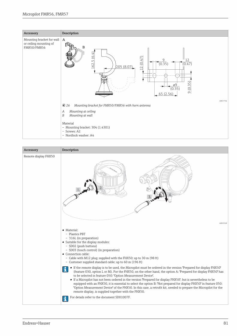
Micropilot FMR56, FMR57
Endress+Hauser 81
Accessory Description
Mounting bracket for wallor ceiling mounting ofFMR50/FMR56
A
B
16
2.5
(6
.4)
205 (8.07)
12
(0
.47
)
65 (2.56)
9(0.35)
9 (
0.3
5)
12(0.47)
ø9(0.35)
A0017746
26 Mounting bracket for FMR50/FMR56 with horn antenna
A Mounting at ceilingB Mounting at wall
Material– Mounting bracket: 304 (1.4301)– Screws: A2– Nordlock washer: A4
Accessory Description
Remote display FHX50
A0019128
• Material:– Plastics PBT– 316L (in preparation)
• Suitable for the display modules:– SD02 (push buttons)– SD03 (touch control) (in preparation)
• Connection cable:– Cable with M12 plug; supplied with the FHX50; up to 30 m (98 ft)– Customer supplied standard cable; up to 60 m (196 ft)
• If the remote display is to be used, the Micropilot must be ordered in the version "Prepared for display FHX50"(feature 030, option L or M). For the FHX50, on the other hand, the option A: "Prepared for display FHX50" hasto be selected in feature 050: "Option Measurement Device".
• If a Micropilot has not been ordered in the version "Prepared for display FHX50", but is nevertheless to beequipped with an FHX50, it is essential to select the option B: "Not prepared for display FHX50" in feature 050:"Option Measurement Device" of the FHX50. In this case, a retrofit kit, needed to prepare the Micropilot for theremote display, is supplied together with the FHX50.
For details refer to the document SD01007F.
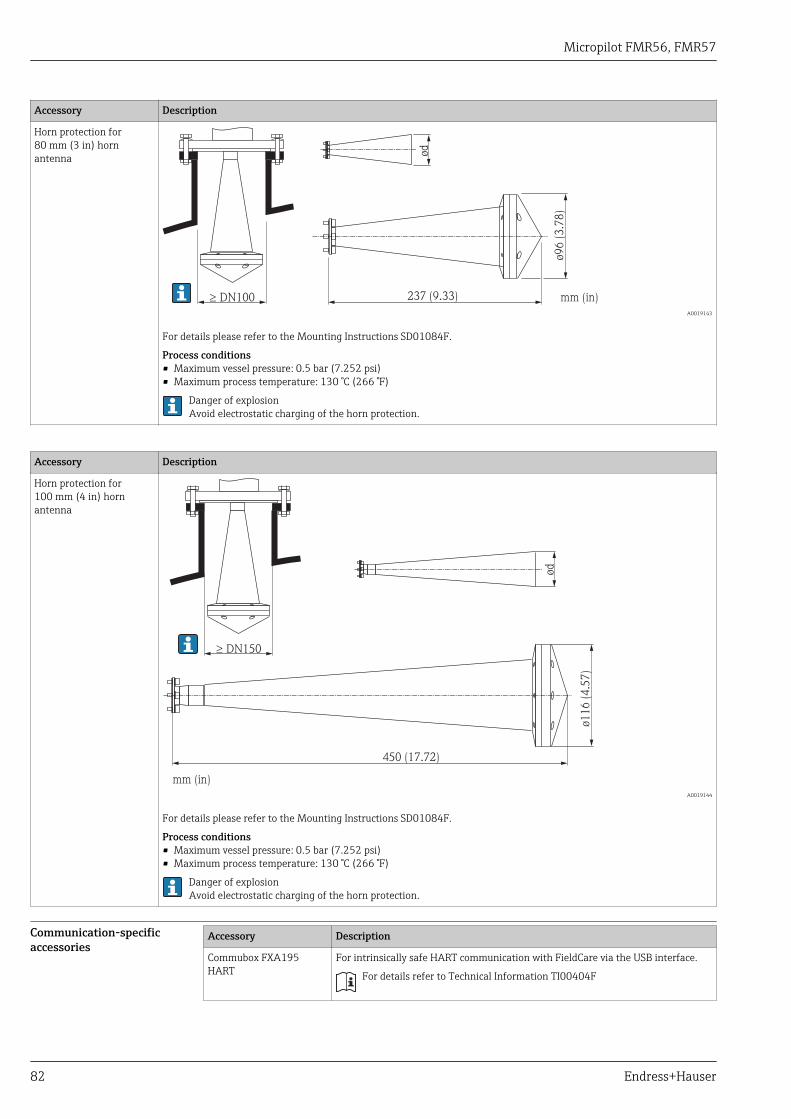
Micropilot FMR56, FMR57
82 Endress+Hauser
Accessory Description
Horn protection for80 mm (3 in) hornantenna
237 (9.33)³ DN100 mm (in)
ø96 (
3.7
8)
ød
A0019143
For details please refer to the Mounting Instructions SD01084F.
Process conditions• Maximum vessel pressure: 0.5 bar (7.252 psi)• Maximum process temperature: 130 °C (266 °F)
Danger of explosionAvoid electrostatic charging of the horn protection.
Accessory Description
Horn protection for100 mm (4 in) hornantenna
450 (17.72)
ø116 (
4.5
7)
mm (in)
ød
³ DN150
A0019144
For details please refer to the Mounting Instructions SD01084F.
Process conditions• Maximum vessel pressure: 0.5 bar (7.252 psi)• Maximum process temperature: 130 °C (266 °F)
Danger of explosionAvoid electrostatic charging of the horn protection.
Communication-specificaccessories
Accessory Description
Commubox FXA195HART
For intrinsically safe HART communication with FieldCare via the USB interface.
For details refer to Technical Information TI00404F
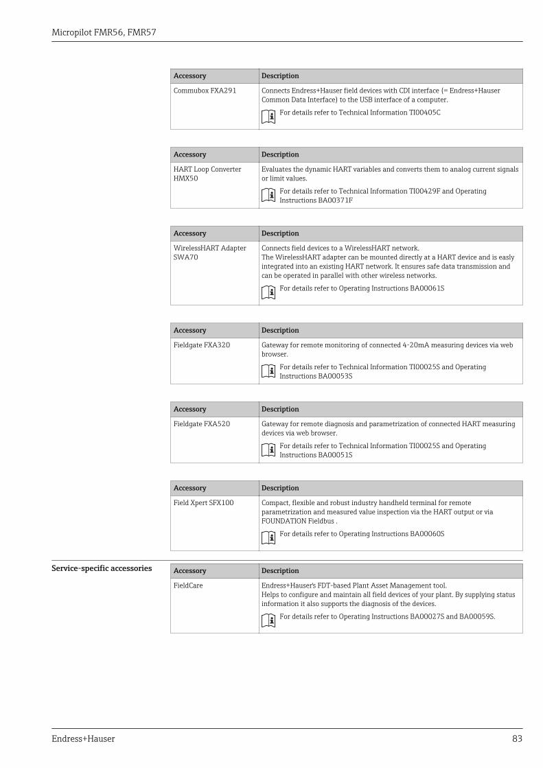
Micropilot FMR56, FMR57
Endress+Hauser 83
Accessory Description
Commubox FXA291 Connects Endress+Hauser field devices with CDI interface (= Endress+HauserCommon Data Interface) to the USB interface of a computer.
For details refer to Technical Information TI00405C
Accessory Description
HART Loop ConverterHMX50
Evaluates the dynamic HART variables and converts them to analog current signalsor limit values.
For details refer to Technical Information TI00429F and OperatingInstructions BA00371F
Accessory Description
WirelessHART AdapterSWA70
Connects field devices to a WirelessHART network.The WirelessHART adapter can be mounted directly at a HART device and is easlyintegrated into an existing HART network. It ensures safe data transmission andcan be operated in parallel with other wireless networks.
For details refer to Operating Instructions BA00061S
Accessory Description
Fieldgate FXA320 Gateway for remote monitoring of connected 4-20mA measuring devices via webbrowser.
For details refer to Technical Information TI00025S and OperatingInstructions BA00053S
Accessory Description
Fieldgate FXA520 Gateway for remote diagnosis and parametrization of connected HART measuringdevices via web browser.
For details refer to Technical Information TI00025S and OperatingInstructions BA00051S
Accessory Description
Field Xpert SFX100 Compact, flexible and robust industry handheld terminal for remoteparametrization and measured value inspection via the HART output or viaFOUNDATION Fieldbus .
For details refer to Operating Instructions BA00060S
Service-specific accessories Accessory Description
FieldCare Endress+Hauser's FDT-based Plant Asset Management tool.Helps to configure and maintain all field devices of your plant. By supplying statusinformation it also supports the diagnosis of the devices.
For details refer to Operating Instructions BA00027S and BA00059S.

Micropilot FMR56, FMR57
84 Endress+Hauser
System components Accessory Description
Graphic Data ManagerMemograph M
The graphic data manager Memograph M provides information on all the relevantprocess variables. Measured values are recorded correctly, limit values aremonitored and measuring points analyzed. The data are stored in the 256 MBinternal memory and also on an SD card or USB stick.
For details refer to Technical Information TI00133R and OperatingInstructions BA00247R
RN221N Active barrier with power supply for safe separation of 4 to 20 mA current circuits.Provides bi-directional HART transmission.
For details refer to Technical Information TI00073R and OperatingInstructions BA00202R
RNS221 Transmitter supply for 2-wire sensors or transmitters exclusively for non-Ex areas.Provides bi-directional communication using the HART communication sockets.
For details refer to Technical Information TI00081R and OperatingInstructions KA00110R
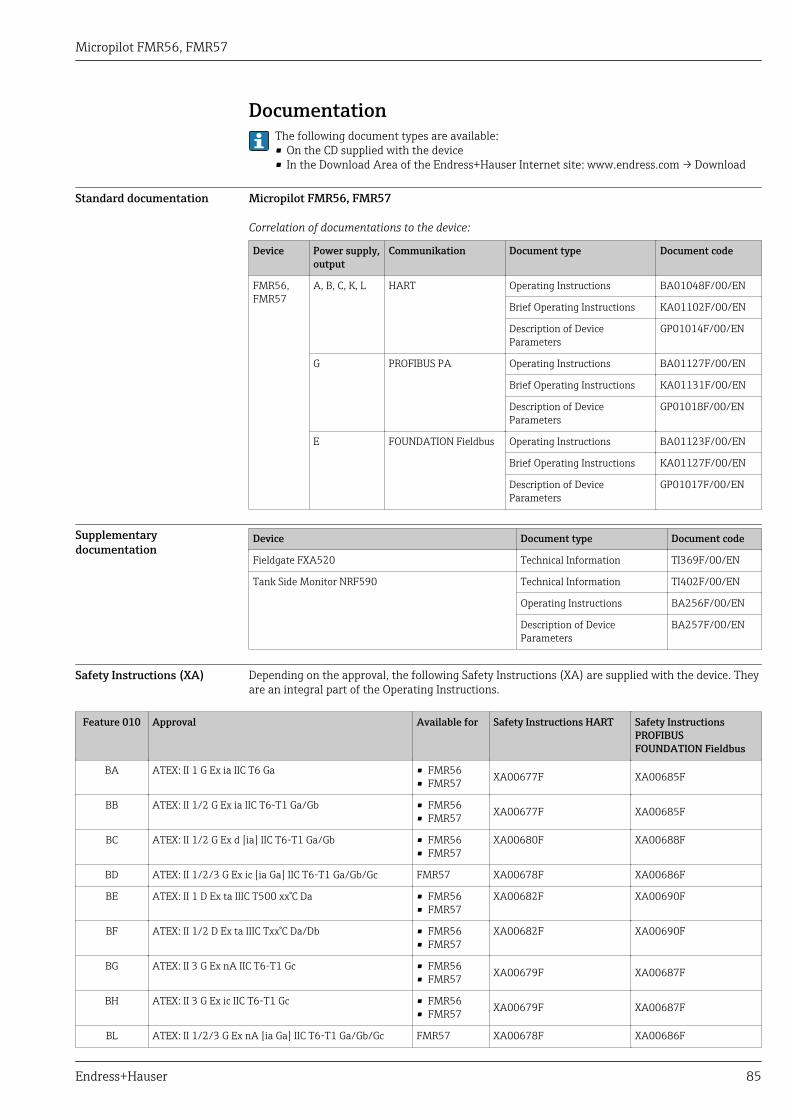
Micropilot FMR56, FMR57
Endress+Hauser 85
DocumentationThe following document types are available:• On the CD supplied with the device• In the Download Area of the Endress+Hauser Internet site: www.endress.com → Download
Standard documentation Micropilot FMR56, FMR57
Correlation of documentations to the device:
Device Power supply,output
Communikation Document type Document code
FMR56,FMR57
A, B, C, K, L HART Operating Instructions BA01048F/00/EN
Brief Operating Instructions KA01102F/00/EN
Description of DeviceParameters
GP01014F/00/EN
G PROFIBUS PA Operating Instructions BA01127F/00/EN
Brief Operating Instructions KA01131F/00/EN
Description of DeviceParameters
GP01018F/00/EN
E FOUNDATION Fieldbus Operating Instructions BA01123F/00/EN
Brief Operating Instructions KA01127F/00/EN
Description of DeviceParameters
GP01017F/00/EN
Supplementarydocumentation
Device Document type Document code
Fieldgate FXA520 Technical Information TI369F/00/EN
Tank Side Monitor NRF590 Technical Information TI402F/00/EN
Operating Instructions BA256F/00/EN
Description of DeviceParameters
BA257F/00/EN
Safety Instructions (XA) Depending on the approval, the following Safety Instructions (XA) are supplied with the device. Theyare an integral part of the Operating Instructions.
Feature 010 Approval Available for Safety Instructions HART Safety InstructionsPROFIBUSFOUNDATION Fieldbus
BA ATEX: II 1 G Ex ia IIC T6 Ga • FMR56• FMR57 XA00677F XA00685F
BB ATEX: II 1/2 G Ex ia IIC T6-T1 Ga/Gb • FMR56• FMR57 XA00677F XA00685F
BC ATEX: II 1/2 G Ex d [ia] IIC T6-T1 Ga/Gb • FMR56• FMR57
XA00680F XA00688F
BD ATEX: II 1/2/3 G Ex ic [ia Ga] IIC T6-T1 Ga/Gb/Gc FMR57 XA00678F XA00686F
BE ATEX: II 1 D Ex ta IIIC T500 xx°C Da • FMR56• FMR57
XA00682F XA00690F
BF ATEX: II 1/2 D Ex ta IIIC Txx°C Da/Db • FMR56• FMR57
XA00682F XA00690F
BG ATEX: II 3 G Ex nA IIC T6-T1 Gc • FMR56• FMR57 XA00679F XA00687F
BH ATEX: II 3 G Ex ic IIC T6-T1 Gc • FMR56• FMR57 XA00679F XA00687F
BL ATEX: II 1/2/3 G Ex nA [ia Ga] IIC T6-T1 Ga/Gb/Gc FMR57 XA00678F XA00686F
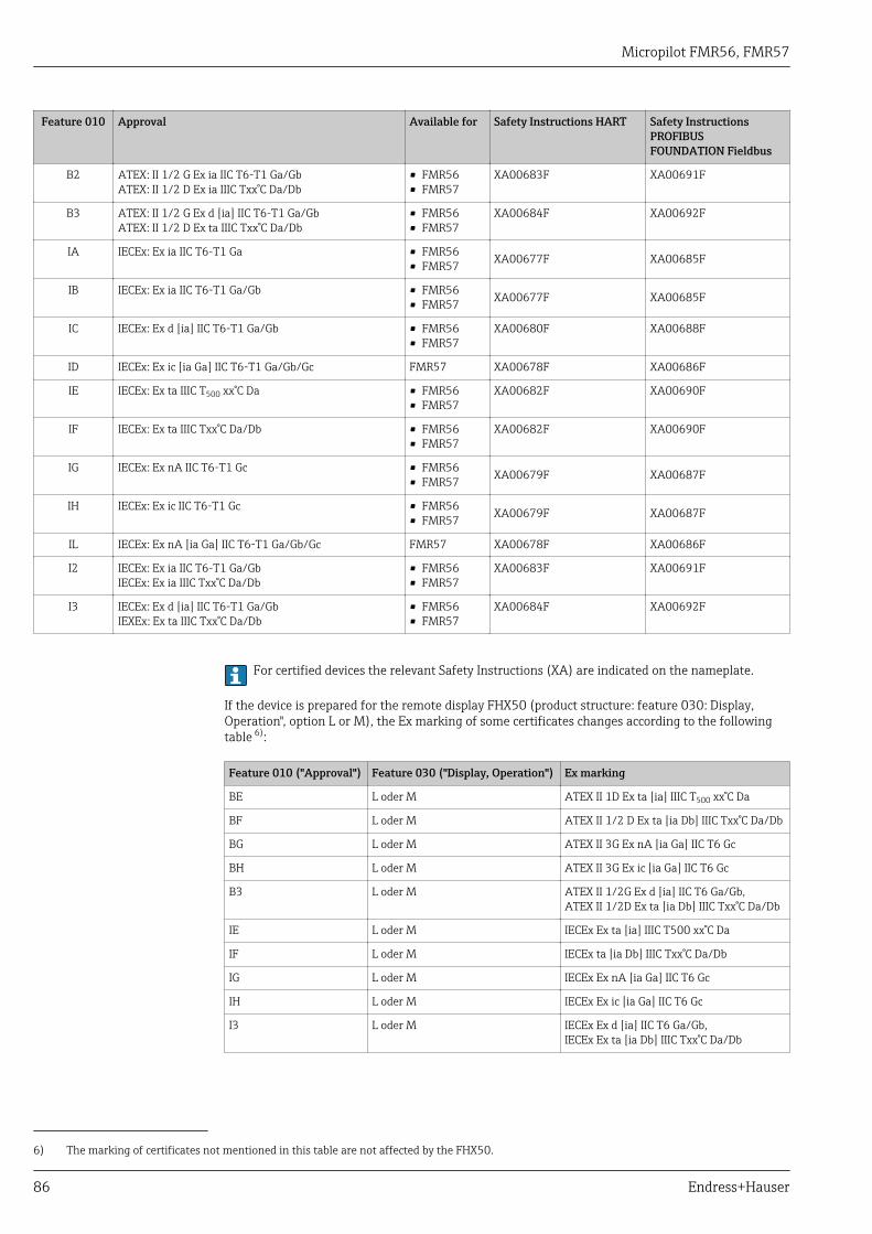
Micropilot FMR56, FMR57
86 Endress+Hauser
Feature 010 Approval Available for Safety Instructions HART Safety InstructionsPROFIBUSFOUNDATION Fieldbus
B2 ATEX: II 1/2 G Ex ia IIC T6-T1 Ga/GbATEX: II 1/2 D Ex ia IIIC Txx°C Da/Db
• FMR56• FMR57
XA00683F XA00691F
B3 ATEX: II 1/2 G Ex d [ia] IIC T6-T1 Ga/GbATEX: II 1/2 D Ex ta IIIC Txx°C Da/Db
• FMR56• FMR57
XA00684F XA00692F
IA IECEx: Ex ia IIC T6-T1 Ga • FMR56• FMR57 XA00677F XA00685F
IB IECEx: Ex ia IIC T6-T1 Ga/Gb • FMR56• FMR57 XA00677F XA00685F
IC IECEx: Ex d [ia] IIC T6-T1 Ga/Gb • FMR56• FMR57
XA00680F XA00688F
ID IECEx: Ex ic [ia Ga] IIC T6-T1 Ga/Gb/Gc FMR57 XA00678F XA00686F
IE IECEx: Ex ta IIIC T500 xx°C Da • FMR56• FMR57
XA00682F XA00690F
IF IECEx: Ex ta IIIC Txx°C Da/Db • FMR56• FMR57
XA00682F XA00690F
IG IECEx: Ex nA IIC T6-T1 Gc • FMR56• FMR57 XA00679F XA00687F
IH IECEx: Ex ic IIC T6-T1 Gc • FMR56• FMR57 XA00679F XA00687F
IL IECEx: Ex nA [ia Ga] IIC T6-T1 Ga/Gb/Gc FMR57 XA00678F XA00686F
I2 IECEx: Ex ia IIC T6-T1 Ga/GbIECEx: Ex ia IIIC Txx°C Da/Db
• FMR56• FMR57
XA00683F XA00691F
I3 IECEx: Ex d [ia] IIC T6-T1 Ga/GbIEXEx: Ex ta IIIC Txx°C Da/Db
• FMR56• FMR57
XA00684F XA00692F
For certified devices the relevant Safety Instructions (XA) are indicated on the nameplate.
If the device is prepared for the remote display FHX50 (product structure: feature 030: Display,Operation", option L or M), the Ex marking of some certificates changes according to the followingtable 6):
Feature 010 ("Approval") Feature 030 ("Display, Operation") Ex marking
BE L oder M ATEX II 1D Ex ta [ia] IIIC T500 xx°C Da
BF L oder M ATEX II 1/2 D Ex ta [ia Db] IIIC Txx°C Da/Db
BG L oder M ATEX II 3G Ex nA [ia Ga] IIC T6 Gc
BH L oder M ATEX II 3G Ex ic [ia Ga] IIC T6 Gc
B3 L oder M ATEX II 1/2G Ex d [ia] IIC T6 Ga/Gb,ATEX II 1/2D Ex ta [ia Db] IIIC Txx°C Da/Db
IE L oder M IECEx Ex ta [ia] IIIC T500 xx°C Da
IF L oder M IECEx ta [ia Db] IIIC Txx°C Da/Db
IG L oder M IECEx Ex nA [ia Ga] IIC T6 Gc
IH L oder M IECEx Ex ic [ia Ga] IIC T6 Gc
I3 L oder M IECEx Ex d [ia] IIC T6 Ga/Gb,IECEx Ex ta [ia Db] IIIC Txx°C Da/Db
6) The marking of certificates not mentioned in this table are not affected by the FHX50.
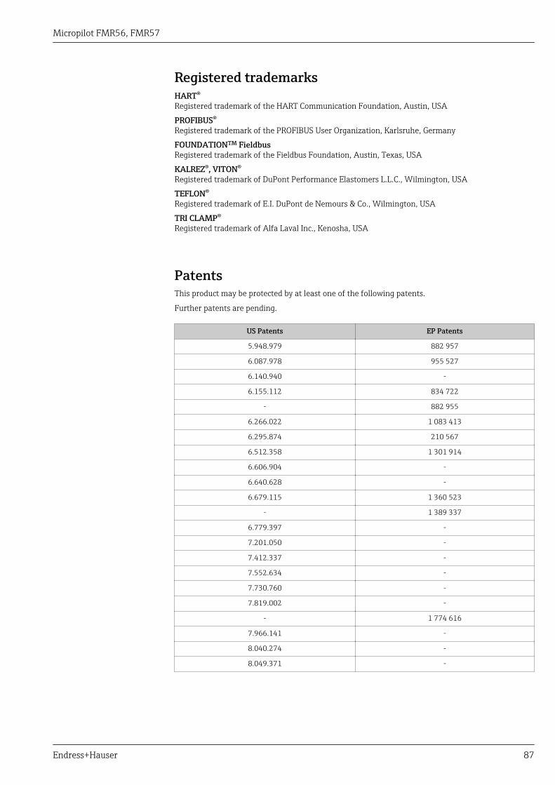
Micropilot FMR56, FMR57
Endress+Hauser 87
Registered trademarksHART®
Registered trademark of the HART Communication Foundation, Austin, USA
PROFIBUS®
Registered trademark of the PROFIBUS User Organization, Karlsruhe, Germany
FOUNDATIONTM FieldbusRegistered trademark of the Fieldbus Foundation, Austin, Texas, USA
KALREZ®, VITON®
Registered trademark of DuPont Performance Elastomers L.L.C., Wilmington, USA
TEFLON®
Registered trademark of E.I. DuPont de Nemours & Co., Wilmington, USA
TRI CLAMP®
Registered trademark of Alfa Laval Inc., Kenosha, USA
PatentsThis product may be protected by at least one of the following patents.
Further patents are pending.
US Patents EP Patents
5.948.979 882 957
6.087.978 955 527
6.140.940 -
6.155.112 834 722
- 882 955
6.266.022 1 083 413
6.295.874 210 567
6.512.358 1 301 914
6.606.904 -
6.640.628 -
6.679.115 1 360 523
- 1 389 337
6.779.397 -
7.201.050 -
7.412.337 -
7.552.634 -
7.730.760 -
7.819.002 -
- 1 774 616
7.966.141 -
8.040.274 -
8.049.371 -

www.addresses.endress.com
*71224360*71224360