technical data
RQ-B8V3B_RQ-B9W1B
Pair, Twin, Triple Application
air conditioning systems
SplitSky Air

• Split Sky Air • Outdoor Units 1
• Outdoor Units • R-410A • RQ-B8V3B_RQ-B9W1B
TABLE OF CONTENTSRQ-B8V3B_RQ-B9W1B
1 Features . . . . . . . . . . . . . . . . . . . . . . . . . . . . . . . . . . . . . . . . . . . . . . . . . . . . . . . . . . . . . 2
2 Specifications . . . . . . . . . . . . . . . . . . . . . . . . . . . . . . . . . . . . . . . . . . . . . . . . . . . . . . . 3 Nominal Capacity and Nominal Input . . . . . . . . . . . . . . . . . . . . . . . . . . . . . . . 3 Technical Specifications . . . . . . . . . . . . . . . . . . . . . . . . . . . . . . . . . . . . . . . . . . . . . 4 Electrical Specifications . . . . . . . . . . . . . . . . . . . . . . . . . . . . . . . . . . . . . . . . . . . . . 5
3 Electrical data . . . . . . . . . . . . . . . . . . . . . . . . . . . . . . . . . . . . . . . . . . . . . . . . . . . . . . . 6
4 Safety device settings . . . . . . . . . . . . . . . . . . . . . . . . . . . . . . . . . . . . . . . . . . . . . 9
5 Options . . . . . . . . . . . . . . . . . . . . . . . . . . . . . . . . . . . . . . . . . . . . . . . . . . . . . . . . . . . . . 10
6 Capacity tables . . . . . . . . . . . . . . . . . . . . . . . . . . . . . . . . . . . . . . . . . . . . . . . . . . . . 11Combination table . . . . . . . . . . . . . . . . . . . . . . . . . . . . . . . . . . . . . . . . . . . . . . . . . . . 11Cooling capacity tables . . . . . . . . . . . . . . . . . . . . . . . . . . . . . . . . . . . . . . . . . . . . . 12Cooling capacity tables simultaneous operation . . . . . . . . . . . . . . . . . . . . 18Heating capacity tables . . . . . . . . . . . . . . . . . . . . . . . . . . . . . . . . . . . . . . . . . . . . . 19Heating capacity tables simultaneous operation . . . . . . . . . . . . . . . . . . . . 26
7 Dimensional drawing & centre of gravity . . . . . . . . . . . . . . . . . . . . . . . 27Dimensional drawing . . . . . . . . . . . . . . . . . . . . . . . . . . . . . . . . . . . . . . . . . . . . . . . . 27Centre of gravity . . . . . . . . . . . . . . . . . . . . . . . . . . . . . . . . . . . . . . . . . . . . . . . . . . . . 29
8 Piping diagram. . . . . . . . . . . . . . . . . . . . . . . . . . . . . . . . . . . . . . . . . . . . . . . . . . . . . 31
9 Wiring diagram. . . . . . . . . . . . . . . . . . . . . . . . . . . . . . . . . . . . . . . . . . . . . . . . . . . . . 33Wiring diagram . . . . . . . . . . . . . . . . . . . . . . . . . . . . . . . . . . . . . . . . . . . . . . . . . . . . . . 33External connection diagram . . . . . . . . . . . . . . . . . . . . . . . . . . . . . . . . . . . . . . . . 35
10 Sound data . . . . . . . . . . . . . . . . . . . . . . . . . . . . . . . . . . . . . . . . . . . . . . . . . . . . . . . . . 36Sound pressure spectrum . . . . . . . . . . . . . . . . . . . . . . . . . . . . . . . . . . . . . . . . . . . 36Sound power spectrum . . . . . . . . . . . . . . . . . . . . . . . . . . . . . . . . . . . . . . . . . . . . . 38
11 Operation range . . . . . . . . . . . . . . . . . . . . . . . . . . . . . . . . . . . . . . . . . . . . . . . . . . . 39

• Outdoor Units • R-410A • RQ-B8V3B_RQ-B9W1B
1
• Split Sky Air • Outdoor Units2
1 Features
Outdoor Uni Split Sky RQ-B8V3B_RQ-B R-410a • Outdoor units for pair, twin, triple, double twin application
• Daikin outdoor units are neat and sturdy and can be mounted easily on a roof or terrace or simply placed against an outside wall.
• Outdoor units are fitted with a scroll compressor, renowned for low noise and high energy efficiency.
• The piping connections can be accessed from underneath, front, side or rear.
• The sevice valves are hidden inside the casing.
• A special acryl precoated fin for anti-corrosion treatment on the heat exchanger ensures greater resistance against severe weather conditions

3
2
• Split Sky Air • Outdoor Units 3
• Outdoor Units • R-410A • RQ-B8V3B_RQ-B9W1B
2 Specifications
2-1 NOMINAL CAPACITY AND NOMINAL INPUT RQ71B8V3B RQ71B8W1B RQ100B8V3B RQ100B8W1B RQ125B8W1B
For combination indoor units + outdoor units
Indoor Units FCQ71B8V3B FCQ71B8V3B FCQ100B8V3B FCQ100B8V3B FCQ125B8V3B
Nominal Capacity
Cooling Standard kW 7.1 7.1 10 10 12.5Heating Standard kW 8 8 11.2 11.2 14.6
Nominal input Cooling Standard kW 2.72 2.66 3.83 3.56 4.66Heating Standard kW 2.85 2.80 3.75 3.66 5.06
For combination indoor units + outdoor units
EER Cooling 2.61 2.67 2.61 2.81 2.68COP Heating 2.81 2.86 2.99 3.06 2.89Energy Labeling Directive
Cooling D D D C DHeating D
Annual energy consumption kWh 1360 1330 1915 1780 2330Indoor Units FBQ71B8V3B FBQ71B8V3B FBQ100B8V3B FBQ100B8V3B FBQ125B8V3B
Nominal Capacity
Cooling Standard kW 7.1 7.1 10 10 12.2Heating Standard kW 8 8 11.2 11.2 14.5
Nominal input Cooling Standard kW 2.79 2.68 3.79 3.6 4.67Heating Standard kW 2.49 2.49 3.91 3.87 4.52
For combination indoor units + outdoor units
EER Cooling 2.54 2.65 2.64 2.78 2.61COP Heating 3.21 3.21 2.86 2.89 3.21Energy Labeling Directive
Cooling E D D C DHeating C C D D C
Annual energy consumption kWh 1395 1340 1885 1780 2335Indoor Units FHQ71BVV1B FHQ71BVV1B FHQ100BVV1B FHQ100BVV1B FHQ125BVV1B
Nominal Capacity
Cooling Standard kW 7.1 7.1 9.8 9.8 12.2Heating Standard kW 8 8 11.2 11.2 14.5
Nominal input Cooling Standard kW 2.7 2.65 3.75 3.68 4.51Heating Standard kW 2.85 2.8 4.13 4.01 5.16
For combination indoor units + outdoor units
EER Cooling 2.63 2.68 2.61 2.66 2.71COP Heating 2.81 2.86 2.71 2.79 2.81Energy Labeling Directive
Cooling DHeating D D E E D
Annual energy consumption kWh 1350 1325 1875 1840 2250Indoor Units FAQ71BVV1B FAQ71BVV1B FAQ100BVV1B FAQ100BVV1B FUQ125BVV1B
Nominal Capacity
Cooling Standard kW 7.1 7.1 10 10 12.2Heating Standard kW 8 8 11.2 11.2 14.5
Nominal input Cooling Standard kW 2.65 2.53 3.56 3.52 4.57Heating Standard kW 2.58 2.49 3.96 3.82 4.88
For combination indoor units + outdoor units
EER Cooling 2.68 2.81 2.81 2.84 2.67COP Heating 3.10 3.21 2.83 2.93 2.97Energy Labeling Directive
Cooling D C C C DHeating D C D D D
Annual energy consumption kWh 1325 1265 1780 1760 2285Indoor Units FUQ71BVV1B FUQ71BVV1B FUQ100BVV1B FUQ100BVV1B FDQ125B8V3B
Nominal Capacity
Cooling Standard kW 7.1 7.1 10 10 12.5Heating Standard kW 8 8 11.2 11.2 14.6
Nominal input Cooling Standard kW 2.7 2.65 3.83 3.78 4.79Heating Standard kW 2.53 2.44 3.58 3.54 4.51
For combination indoor units + outdoor units
EER Cooling 2.63 2.68 2.61 2.65 2.61COP Heating 3.16 3.28 3.13 3.16 3.24Energy Labeling Directive
Cooling DHeating D C D D C
Annual energy consumption kWh 1350 1325 1915 1890 2395

• Outdoor Units • R-410A • RQ-B8V3B_RQ-B9W1B
2
• Split Sky Air • Outdoor Units4
2 Specifications
2-2 TECHNICAL SPECIFICATIONS RQ71B8V3B RQ71B8W1B RQ100B8V3B RQ100B8W1B RQ125B8W1B
Casing Colour Daikin WhiteMaterial Painted galvanized steel plate
Dimensions Unit Height mm 770 770 1170 1170 1170Width mm 900 900 900 900 900Depth mm 320 320 320 320 320
Packing Height mm 900 900 1300 1300 1300Width mm 980 980 980 980 980Depth mm 420 420 420 420 420
Weight Unit kg 84 83 103 101 108Packed Unit kg 88 87 108 106 113
Heat Exchanger
Dimensions Length mm 857 857 857 857 857Nr of Rows 2 2 2 2 2Fin Pitch mm 2.00 2.00 2.00 2.00 2.00Nr of Passes 6 6 10 10 10Face Area m² 0.641 0.641 0.980 0.980 0.980Nr of Stages 34 34 52 52 52
Tube type Hi-XSS cooling tubeFin Type Non-symmetric waffle louvre
Treatment Anti-corrosion treatment (PE)Fan Type Direct Drive Propeller
Discharge direction HorizontalQuantity 1 1 1 1 2Air Flow Rate (nominal at 230V)
Cooling m³/min 48.0 48.0 55.0 55.0 89.0Heating m³/min 43.0 43.0 50.0 50.0 80.0
Motor Quantity 1 1 1 1 1Model P47L11SPosition Lower
Motor Speed (nominal)
Steps 3 3 3 3 3
Fan Motor Output W 65 65 90 90 85Position Upper
Motor Speed (nominal)
Steps 3
Fan Motor Output W 65Compressor Quantity 1 1 1 1 1
Motor Model JT90G-P4V1N@S JT90G-YE JT125G-P4V1@S JT125G-YE JT160G-YEType Hermetically sealed scroll compressorMotor Output
W 2200 2200 3000 3000 3750
Crankcase Heater
W 33 33 33 33 33
Operation Range
Cooling Min ° CDB -5.0 -5.0 -5.0 -5.0 -5.0Max ° CDB 46.0 46.0 46.0 46.0 46.0
Heating Min ° CWB -10 -10 -10 -10 -10Max ° CWB 15 15 15 15 15
Sound Level (nominal)
Cooling Sound Power
dBA 63.0 63.0 66.0 66.0 67.0
Sound Pressure
dBA 50.0 50.0 53.0 53.0 53.0
Refrigerant Type R-410ACharge kg 2.7 2.7 3.7 3.7 3.7Control Expansion valve (electronic type)Nr of Circuits 1 1 1 1 1
Refrigerant Oil Type Daphne FVC68DCharged Volume l 1.5 1.5 1.5 1.5 1.5

2
• Split Sky Air • Outdoor Units 5
• Outdoor Units • R-410A • RQ-B8V3B_RQ-B9W1B
2 Specifications
Piping connections
Liquid (OD) Quantity 1 1 1 1 1Type Flare connectionDiameter (OD)
mm 9.52 9.52 9.52 9.52 9.52
Gas Quantity 1 1 1 1 1Type Flare connectionDiameter (OD)
mm 15.9 15.9 15.9 15.9 15.9
Drain Quantity 3 3 3 3 3Type HoleDiameter (OD)
mm 26 26 26 26 26
Piping Length Minimum m 5 5 5 5 5Maximum m 70 70 70 70 70Equivalent m 90 90 90 90 90Chargeless m 30 30 30 30 30
Installation height difference
Maximum m 30.0 30.0 30.0 30.0 30.0
Max. internunit level difference
m 0.5 0.5 0.5 0.5 0.5
Heat Insulation Both liquid and gas pipesDefrost Method Reversed cycleDefrost Control Sensor for outdoor heat exchanger temperatureCapacity Control Method NoneSafety Devices Reverse phase protector
PC board fuseOvercurrent relay (compressor)
Low pressure switchHigh pressure switch
Fan motor thermal protectorStandard Accessories
Item Declaration of conformityQuantity 1 1 1 1 1Item Installation manualQuantity 1 1 1 1 1
Notes Sound pressure level is a relative value, depending on the distance and acoustic environment. For more details, please refer to sound level drawings of this chapter.
The sound power level is an absolute value indicating the power which a sound source generates.Sound values are measured in a semi-anechoic room.
Heating capacity is only applicable for combination with heat pump outdoor unitIn case of drain piping for outdoor unit, drain piping kit (option) is needed.
Nominal cooling capacities are based on : indoor temperature : 27°CDB, 19°CWB, outdoor temperature : 35°CDB, equivalent refrigerant piping : 7.5m, level difference : 0m.
Nominal heating capacities are based on : indoor temperature : 20°CDB, outdoor temperature : 7°CDB, 6°CWB, equivalent refrigerant piping : 7.5m, level difference : 0m
2-3 ELECTRICAL SPECIFICATIONS RQ71B8V3B RQ71B8W1B RQ100B8V3B RQ100B8W1B RQ125B8W1B
Power Supply Name V3 W1 V3 W1 W1Phase 1 3N 1 3N 3NFrequency Hz 50 50 50 50 50Voltage V 230 400 230 400 400Voltage range Minimum V -10%
Maximum V +10%Current Recomended fuses A 32 16 40 16 20Wiring connections
For Power Supply
Quantity 1 1 1 1 1Remark 3 wires (earth wire
included)5 wires (earth wire
included)3 wires (earth wire
included)5 wires (earth wire
included)5 wires (earth wire
included)For connection with indoor
Quantity 1 1 1 1 1Remark 4 wires (earth wire included)
Power Supply Intake Outdoor unit only
2-2 TECHNICAL SPECIFICATIONS RQ71B8V3B RQ71B8W1B RQ100B8V3B RQ100B8W1B RQ125B8W1B
• Outdoor Units • R-410A • RQ-B8V3B_RQ-B9W1B
13
• Split Sky Air • Outdoor Units6
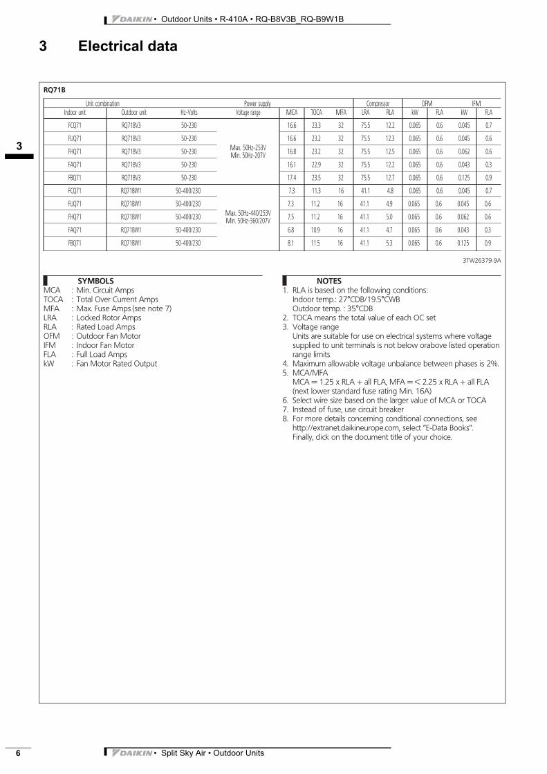
3 Electrical data
RQ71B
Unit combination Power supply Compressor OFM IFMIndoor unit Outdoor unit Hz-Volts Voltage range MCA TOCA MFA LRA RLA kW FLA kW FLA
FCQ71 RQ71BV3 50-230
Max. 50Hz-253VMin. 50Hz-207V
16.6 23.3 32 75.5 12.2 0.065 0.6 0.045 0.7
FUQ71 RQ71BV3 50-230 16.6 23.2 32 75.5 12.3 0.065 0.6 0.045 0.6
FHQ71 RQ71BV3 50-230 16.8 23.2 32 75.5 12.5 0.065 0.6 0.062 0.6
FAQ71 RQ71BV3 50-230 16.1 22.9 32 75.5 12.2 0.065 0.6 0.043 0.3
FBQ71 RQ71BV3 50-230 17.4 23.5 32 75.5 12.7 0.065 0.6 0.125 0.9
FCQ71 RQ71BW1 50-400/230
Max. 50Hz-440/253VMin. 50Hz-360/207V
7.3 11.3 16 41.1 4.8 0.065 0.6 0.045 0.7
FUQ71 RQ71BW1 50-400/230 7.3 11.2 16 41.1 4.9 0.065 0.6 0.045 0.6
FHQ71 RQ71BW1 50-400/230 7.5 11.2 16 41.1 5.0 0.065 0.6 0.062 0.6
FAQ71 RQ71BW1 50-400/230 6.8 10.9 16 41.1 4.7 0.065 0.6 0.043 0.3
FBQ71 RQ71BW1 50-400/230 8.1 11.5 16 41.1 5.3 0.065 0.6 0.125 0.9
3TW26379-9A
SYMBOLSMCA : Min. Circuit AmpsTOCA : Total Over Current AmpsMFA : Max. Fuse Amps (see note 7)LRA : Locked Rotor AmpsRLA : Rated Load AmpsOFM : Outdoor Fan MotorIFM : Indoor Fan MotorFLA : Full Load AmpskW : Fan Motor Rated Output
NOTES1. RLA is based on the following conditions:
Indoor temp.: 27°CDB/19.5°CWBOutdoor temp. : 35°CDB
2. TOCA means the total value of each OC set3. Voltage range
Units are suitable for use on electrical systems where voltagesupplied to unit terminals is not below orabove listed operationrange limits
4. Maximum allowable voltage unbalance between phases is 2%.5. MCA/MFA
MCA = 1.25 x RLA + all FLA, MFA = < 2.25 x RLA + all FLA(next lower standard fuse rating Min. 16A)
6. Select wire size based on the larger value of MCA or TOCA7. Instead of fuse, use circuit breaker8. For more details concerning conditional connections, see
http://extranet.daikineurope.com, select ’’E-Data Books’’.Finally, click on the document title of your choice.

3
• Split Sky Air • Outdoor Units 7
• Outdoor Units • R-410A • RQ-B8V3B_RQ-B9W1B
3 Electrical data
RQ100B
Unit combination Power supply Compressor OFM IFMIndoor unit Outdoor unit Hz-Volts Voltage range MCA TOCA MFA LRA RLA kW FLA kW FLA
FCQ100 RQ100BV3 50-230
Max. 50Hz-253VMin. 50Hz-207V
23.8 34.8 40 98.5 17.6 0.090 0.8 0.090 1.0
FUQ100 RQ100BV3 50-230 23.3 34.9 40 98.5 17.1 0.090 0.8 0.090 1.1
FHQ100 RQ100BV3 50-230 25.3 34.5 40 98.5 19.0 0.090 0.8 0.130 0.7
FAQ100 RQ100BV3 50-230 24.5 34.2 40 98.5 18.6 0.090 0.8 0.049 0.4
FBQ100 RQ100BV3 50-230 23.2 34.8 40 98.5 17.1 0.090 0.8 0.135 1.0
FCQ100 RQ100BW1 50-400/230
Max. 50Hz-440/253VMin. 50Hz-360/207V
9.2 11.8 16 48.2 5.9 0.090 0.8 0.090 1.0
FUQ100 RQ100BW1 50-400/230 8.9 11.9 16 48.2 5.6 0.090 0.8 0.090 1.1
FHQ100 RQ100BW1 50-400/230 9.4 11.5 16 48.2 6.3 0.090 0.8 0.130 0.7
FAQ100 RQ100BW1 50-400/230 8.8 11.2 16 48.2 6.1 0.090 0.8 0.049 0.4
FBQ100 RQ100BW1 50-400/230 8.9 11.8 16 48.2 5.7 0.090 0.8 0.135 1.0
3TW26349-9B
SYMBOLSMCA : Min. Circuit AmpsTOCA : Total Over Current AmpsMFA : Max. Fuse Amps (see note 7)LRA : Locked Rotor AmpsRLA : Rated Load AmpsOFM : Outdoor Fan MotorIFM : Indoor Fan MotorFLA : Full Load AmpskW : Fan Motor Rated Output
NOTES1. RLA is based on the following conditions:
Indoor temp.: 27°CDB/19.5°CWBOutdoor temp. : 35°CDB
2. TOCA means the total value of each OC set3. Voltage range
Units are suitable for use on electrical systems where voltagesupplied to unit terminals is not below orabove listed operationrange limits
4. Maximum allowable voltage unbalance between phases is 2%.5. MCA/MFA
MCA = 1.25 x RLA + all FLA, MFA = < 2.25 x RLA + all FLA(next lower standard fuse rating Min. 16A)
6. Select wire size based on the larger value of MCA or TOCA7. Instead of fuse, use circuit breaker8. For more details concerning conditional connections, see
http://extranet.daikineurope.com, select ’’E-Data Books’’.Finally, click on the document title of your choice.

• Outdoor Units • R-410A • RQ-B8V3B_RQ-B9W1B
3
• Split Sky Air • Outdoor Units8
3 Electrical data
RQ125B
Unit combination Power supply Compressor OFM IFMIndoor unit Outdoor unit Hz-Volts Voltage range MCA TOCA MFA LRA RLA kW FLA kW FLA
FCQ125 RQ125BW1 50-400/230
Max. 50Hz-440/253VMin. 50Hz-360/207V
12.4 15.3 20 63 8.10.065
+0.085
0.6+0.7
0.09 1.0
FUQ125 RQ125BW1 50-400/230 12.2 15.4 20 63 7.80.065
+0.085
0.6+0.7
0.09 1.1
FHQ125 RQ125BW1 50-400/230 12.3 15.0 20 63 8.20.065
+0.085
0.6+0.7
0.13 0.7
FBQ125 RQ125BW1 50-400/230 12.2 15.7 20 63 7.60.065
+0.085
0.6+0.7
0.225 1.4
FDQ125 RQ125BW1 50-400/230 14.9 18.5 20 63 7.50.065
+0.085
0.6+0.7
0.5 4.2
3TW26369-9B
SYMBOLSMCA : Min. Circuit AmpsTOCA : Total Over Current AmpsMFA : Max. Fuse Amps (see note 7)LRA : Locked Rotor AmpsRLA : Rated Load AmpsOFM : Outdoor Fan MotorIFM : Indoor Fan MotorFLA : Full Load AmpskW : Fan Motor Rated Output
NOTES1. RLA is based on the following conditions:
Indoor temp.: 27°CDB/19.5°CWBOutdoor temp. : 35°CDB
2. TOCA means the total value of each OC set3. Voltage range
Units are suitable for use on electrical systems where voltagesupplied to unit terminals is not below orabove listed operationrange limits
4. Maximum allowable voltage unbalance between phases is 2%.5. MCA/MFA
MCA = 1.25 x RLA + all FLA, MFA = < 2.25 x RLA + all FLA(next lower standard fuse rating Min. 16A)
6. Select wire size based on the larger value of MCA or TOCA7. Instead of fuse, use circuit breaker8. For more details concerning conditional connections, see
http://extranet.daikineurope.com, select ’’E-Data Books’’.Finally, click on the document title of your choice.

4
• Split Sky Air • Outdoor Units 9
• Outdoor Units • R-410A • RQ-B8V3B_RQ-B9W1B
4 Safety device settings
RR-RQ
4TW26321-2B
Safety device model
RQ71BV3 RQ100BV3 RQ125BW1 RR71BV3 RR100BV3 RR125BW1
RQ71BW1 RQ100BW1 RR71BW1 RR100BW1
REQ71BV3 REQ100BV3 REQ125BW1
REQ71BW1 REQ100BW1
Fan motor thermal protectorOff 135 +5°C
On 95 +15°C
HPSOff 4,15 +0/-0.10 Mpa
On 3.2 +0.15/-0.15 Mpa
LPSOff -0.03 +0.02/-0.02 Mpa
On 0.05 +0.03/-0.03 Mpa
Max discharge temperature By thermistor and software control
Overcurrent relay By overcurrent sensor and software control

• Outdoor Units • R-410A • RQ-B8V3B_RQ-B9W1B
5
• Split Sky Air • Outdoor Units10
5 Options
Available option for RQ71-125B(V3, W1) and RR71-125B(V3, W1)
Name of optionKit name
RQ71B RQ100B RQ125B RR71B RR100B RR125B
Central drain plug KKPJ5F180
Refrigerant branch piping Twin KHRQ22M20TA
Triple - KHRQ127H - KHRQ127H
3TW26329-1A

3
6
• Split Sky Air • Outdoor Units 11
• Outdoor Units • R-410A • RQ-B8V3B_RQ-B9W1B
6 Capacity tables6 - 1 Combination table
3TW26329-3
Possible combinations and standard capacity for twin and triple operation
1 Possible indoor types:FCQ 35-71FFQ 35-60FUQ 71FHQ 35-71FAQ 71FBQ 35-71
2 Individual indoor capacities are not given because the combinations are for simultaneous operation (= indoor units installed in same room).
3 When different indoor models are used in combination, designate the remote controller that is equipped with the most functions as the main unit.
4 Between brackets are the required Refnet kits mentioned, that are necessary to install the combination.
5 For unit specification of the outdoor units and the indoor units refer to the unit sepcifications mentioned for pair systems.
6 Nominal cooling capacities are based on the following conditions: indoor air temperature: 27°CDB, 19°CWB, outdoor temperature: 35°CDB.Nominal heating capacities are based on the following conditions: indoor air temperature: 20°CDB, outdoor temperature 7°CDB, 6°CWB.
Outdoor models
Possible indoor combination
Simultaneous operation
Twin Triple
RQ71BV3/W1RR71BV3/W1
35-35(KHRQ22M20TA7)
RQ100BV3/W1RR100BV3/W1
50-50(KHRQ22M20TA7)
50-60(KHRQ22M20TA7)
35-71(KHRQ22M20TA7)
35-35-35(KHRQ127H7)
RQ125BW1RR125BW1
60-60(KHRQ22M20TA7)
50-71(KHRQ22M20TA7)
50-50-50(KHRQ127H7)
OUT
IN IN
OUT
IN ININ

• Outdoor Units • R-410A • RQ-B8V3B_RQ-B9W1B
6
• Split Sky Air • Outdoor Units12
6 Capacity tables6 - 2 Cooling capacity tables
FAQ71-100B + RQ71-100BV3 / RQ71-100BW1
3TW26322-5
Cooling capacity
SYMBOLS
FR: Air flow rate [m3/min.]
BF: Bypass factor
EWB: Entering wet bulb temp. [°CWB]
EDB: Entering dry bulb temp. [°CDB]
DB*: Dry bulb temp. [°CDB]
TC: Total capacity cooling [kW]
SHC: Sensible heat capacity [kW]
PI: Power input (Comp. + indoor + outdoor fan motor) [kW]
CAUTION
TC and SHC are given in kW.
V1/V3: 230V [50 Hz]
W1: 400V [50Hz]
NOTES
1 Ratings shown are net capacities. Influence on fan motor heat is included.
2 shows nominal capacities.
3 SHC is based on each EWB and EDB.SHC* = SHC correction for other dry bulb.
= 0.29 x 60 x AFR [m3/min.] x (1-BF) x (DB*-EDB)/860Add SHC* to SHC if SHC > TC, then TC = SHC.
4 Direct interpolation is permissable. Do not extrapolate.
5 Capacities are based on the folowing conditions.Corresponding refrigerant piping length: 7.5mLevel difference: 0m
6 Air flow rate and BF are tabulated below.
7 Add the following corrections to power input of each model.
OutdoorIndoor Outdoor temperature (°CDB)
EWB(°C)
EDB(°C)
20 25 32 35 40 46TC SHC PI TC SHC PI TC SHC PI TC SHC PI TC SHC PI TC SHC PI
71
12.0 18.0 6.2 4.9 1.81 6.1 4.8 1.97 5.7 4.7 2.20 5.5 4.6 2.36 5.3 4.5 2.60 4.8 4.1 2.8314.0 20.0 6.6 4.9 1.84 6.5 4.8 2.00 6.0 4.7 2.24 5.9 4.6 2.40 5.5 4.5 2.64 5.2 4.1 2.8816.0 22.0 7.2 5.0 1.88 7.0 4.9 2.04 6.5 4.8 2.28 6.3 4.7 2.45 6.0 4.6 2.69 5.4 4.2 2.9318.0 25.0 7.7 5.2 1.92 7.5 5.0 2.09 7.2 4.9 2.34 6.8 4.8 2.50 6.4 4.6 2.76 5.9 4.4 3.0119.0 27.0 8.0 5.3 1.94 7.7 5.2 2.11 7.3 5.0 2.36 7.1 4.8 2.53 6.6 4.7 2.78 6.1 4.5 3.0419.5 27.0 8.0 5.3 1.95 7.9 5.2 2.12 7.4 5.0 2.37 7.2 4.8 2.54 6.7 4.7 2.79 6.2 4.5 3.0522.0 30.0 8.7 5.4 1.98 8.5 5.3 2.16 8.0 5.2 2.42 7.9 4.9 2.59 7.4 4.8 2.85 6.7 4.5 3.1124.0 32.0 9.4 5.4 2.00 9.1 5.3 2.18 8.6 5.2 2.44 8.4 5.0 2.61 8.0 4.8 2.88 7.3 4.5 3.14
100
12.0 18.0 8.4 7.2 2.49 8.3 7.1 2.75 8.1 6.9 3.11 7.8 6.8 3.29 7.5 6.4 3.64 6.8 6.1 4.0814.0 20.0 8.9 7.2 2.53 8.8 7.1 2.80 8.7 6.9 3.16 8.4 6.8 3.34 7.8 6.4 3.71 7.4 6.1 4.1616.0 22.0 10.1 7.3 2.57 9.8 7.2 2.85 9.1 7.0 3.22 8.9 6.9 3.40 8.5 6.5 3.77 7.7 6.2 4.2318.0 25.0 10.8 7.6 2.64 10.5 7.5 2.92 9.8 7.1 3.30 9.6 7.0 3.48 9.0 6.8 3.86 8.3 6.3 4.3319.0 27.0 11.1 7.7 2.66 10.8 7.6 2.95 10.1 7.2 3.33 10.0 7.1 3.52 9.4 6.9 3.90 8.6 6.4 4.3819.5 27.0 11.2 7.7 2.67 11.0 7.6 2.96 10.3 7.2 3.34 10.1 7.1 3.53 9.5 6.9 3.91 8.7 6.4 4.3922.0 30.0 12.2 7.8 2.73 11.8 7.7 3.02 11.2 7.3 3.41 11.0 7.2 3.60 10.4 7.1 3.99 9.5 6.7 4.4824.0 32.0 13.0 7.9 2.75 12.7 7.8 3.05 11.9 7.5 3.44 11.6 7.3 3.64 11.1 7.2 4.03 10.2 6.8 4.52
Model FAQ
71AFR 19BF 0.08
100AFR 23BF 0.1
Model FAQ
71V3 0.12W1 0
100V3 0.04W1 0

6
• Split Sky Air • Outdoor Units 13
• Outdoor Units • R-410A • RQ-B8V3B_RQ-B9W1B
6 Capacity tables6 - 2 Cooling capacity tables
FHQ71-125B + RQ71-100BV3 / RQ71-125BW1
3TW26322-3
Cooling capacity
SYMBOLS
AFR: Air flow rate [m3/min.]
BF: Bypass factor
EWB: Entering wet bulb temp. [°CWB]
EDB: Entering dry bulb temp. [°CDB]
DB*: Dry bulb temp. [°CDB]
TC: Total capacity cooling [kW]
SHC: Sensible heat capacity [kW]
PI: Power input (Comp. + indoor + outdoor fan motor) [kW]
CAUTION
TC and SHC are given in kW.
V1/V3: 230V [50 Hz]
W1: 400V [50Hz]
NOTES
1 Ratings shown are net capacities. Influence on fan motor heat is included.
2 shows nominal capacities.
3 SHC is based on each EWB and EDB.SHC* = SHC correction for other dry bulb.
= 0.29 x 60 x AFR [m3/min.] x (1-BF) x (DB*-EDB)/860Add SHC* to SHC if SHC > TC, then TC = SHC.
4 Direct interpolation is permissable. Do not extrapolate.
5 Capacities are based on the folowing conditions.Corresponding refrigerant piping length: 7.5mLevel difference: 0m
6 Air flow rate and BF are tabulated below.
7 Add the following corrections to power input of each model.
OutdoorIndoor Outdoor temperature (°CDB)
EWB(°C)
EDB(°C)
20 25 32 35 40 46TC SHC PI TC SHC PI TC SHC PI TC SHC PI TC SHC PI TC SHC PI
71
12.0 18.0 6.2 4.8 1.90 6.1 4.7 2.06 5.7 4.6 2.31 5.5 4.5 2.47 5.3 4.4 2.72 4.8 4.0 2.9714.0 20.0 6.6 4.8 1.93 6.5 4.7 2.10 6.0 4.6 2.35 5.9 4.5 2.52 5.5 4.4 2.77 5.2 4.0 3.0216.0 22.0 7.2 4.9 1.96 7.0 4.8 2.13 6.5 4.7 2.39 6.3 4.6 2.56 6.0 4.5 2.82 5.4 4.1 3.0718.0 25.0 7.7 5.1 2.01 7.5 4.9 2.19 7.2 4.8 2.45 6.8 4.7 2.62 6.4 4.5 2.89 5.9 4.3 3.1519.0 27.0 8.0 5.2 2.03 7.7 5.1 2.21 7.3 4.9 2.47 7.1 4.7 2.65 6.6 4.6 2.92 6.1 4.4 3.1819.5 27.0 8.0 5.2 2.04 7.9 5.1 2.22 7.4 4.9 2.48 7.2 4.7 2.66 6.7 4.6 2.92 6.2 4.4 3.1922.0 30.0 8.7 5.3 2.08 8.5 5.2 2.26 8.0 5.1 2.53 7.9 4.8 2.71 7.4 4.7 2.98 6.7 4.4 3.2524.0 32.0 9.4 5.3 2.10 9.1 5.2 2.28 8.6 5.1 2.56 8.4 4.9 2.74 8.0 4.7 3.01 7.3 4.4 3.29
100
12.0 18.0 8.2 6.8 2.60 8.1 6.7 2.88 7.9 6.5 3.25 7.6 6.4 3.43 7.3 6.0 3.81 6.6 5.7 4.2714.0 20.0 8.7 6.8 2.65 8.6 6.7 2.93 8.5 6.5 3.31 8.2 6.4 3.50 7.6 6.0 3.87 7.2 5.7 4.3516.0 22.0 9.9 6.9 2.69 9.6 6.8 2.98 8.9 6.6 3.37 8.7 6.5 3.56 8.3 6.1 3.94 7.5 5.8 4.4218.0 25.0 10.6 7.2 2.76 10.3 7.1 3.05 9.6 6.7 3.45 9.4 6.6 3.64 8.8 6.4 4.04 8.1 5.9 4.5319.0 27.0 10.9 7.3 2.78 10.6 7.2 3.08 9.9 6.8 3.48 9.8 6.7 3.68 9.2 6.5 4.08 8.4 6.0 4.5819.5 27.0 11.0 7.3 2.79 10.8 7.2 3.09 10.1 6.8 3.49 9.9 6.7 3.69 9.3 6.5 4.09 8.5 6.0 4.5922.0 30.0 12.0 7.4 2.85 11.6 7.3 3.16 11.0 6.9 3.56 10.8 6.8 3.77 10.2 6.7 4.17 9.3 6.3 4.6824.0 32.0 12.8 7.5 2.88 12.5 7.4 3.19 11.7 7.1 3.60 11.4 6.9 3.80 10.9 6.8 4.21 10.0 6.4 4.73
125
12.0 18.0 11.1 9.1 3.39 10.8 8.8 3.57 10.0 8.3 3.93 9.7 8.2 4.21 9.2 8.0 4.67 8.5 7.5 5.1214.0 20.0 11.8 9.1 3.45 11.4 8.8 3.64 10.7 8.3 4.00 10.4 8.2 4.28 9.8 8.0 4.75 9.1 7.5 5.2116.0 22.0 12.7 9.2 3.51 12.1 8.9 3.70 11.4 8.4 4.07 11.1 8.3 4.36 10.4 8.1 4.84 9.6 7.6 5.3118.0 25.0 13.3 9.5 3.59 13.0 9.1 3.79 12.1 8.7 4.17 11.8 8.6 4.46 11.2 8.3 4.95 10.3 7.9 5.4319.0 27.0 13.6 9.6 3.63 13.3 9.1 3.83 12.7 8.8 4.21 12.2 8.6 4.51 11.5 8.4 5.00 10.7 8.0 5.4919.5 27.0 13.8 9.6 3.64 13.5 9.1 3.84 12.8 8.8 4.23 12.4 8.7 4.53 11.7 8.4 5.02 10.9 8.0 5.5122.0 30.0 15.1 9.7 3.71 14.6 9.4 3.92 13.7 9.0 4.31 13.4 8.9 4.62 12.9 8.7 5.12 11.9 8.2 5.6224.0 32.0 15.9 9.8 3.75 15.5 9.5 3.96 14.6 9.1 4.35 14.3 9.0 4.66 13.6 8.8 5.17 12.8 8.5 5.67
Model FAQ
71AFR 18BF 0.1
100AFR 24BF 0.14
125AFR 30BF 0.13
Model FAQ
71V3 0.05W1 0
100V3 0.07W1 0
125 W1 0
• Outdoor Units • R-410A • RQ-B8V3B_RQ-B9W1B
6
• Split Sky Air • Outdoor Units14
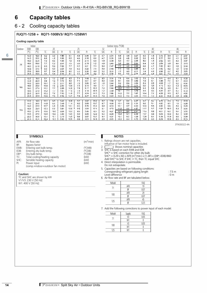
6 Capacity tables6 - 2 Cooling capacity tablesFUQ71-125B + RQ71-100BV3/ RQ71-125BW1
Cooling capacity table
OutdoorIndoor Outdoor temp. (°CDB)
EWB EDB 20 25 32 35 40 46(°C) (°C) TC SHC PI TC SHC PI TC SHC PI TC SHC PI TC SHC PI TC SHC PI
3TW26322-4A
SYMBOLS
AFR: Air flow rate (m3/min)BF: Bypass factorEWB: Entering wet bulb temp. (°CWB)EDB: Entering dry bulb temp. (°CDB)DB*: Dry bulb temp. (°CDB)TC: Total cooling/heating capacity (kW)SHC: Sensible heating capacity (kW)PI: Power input (kW)
(comp.+indoor+outdoor fan motor)
Caution:TC and SHC are shown by kWV1/V3: 230 V [50 Hz]W1: 400 V [50 Hz]
NOTES1. Ratings shown are net capacities.
Influence of fan motor heat is included.2. Shows nominal capacities3. SHC is based on each EWB and EDB
SHC* = SHC correction for other dry bulbSHC* = 0.29 x 60 x AFR (m3/min.) x (1−BF) x (DB*−EDB)/860Add SHC* to SHC if SHC > TC, then TC equal SHC
4. Direct interpolation is permissible.Do not extrapolate.
5. Capacities are based on following conditions:Corresponding refrigerant piping length : 7.5 mLevel difference : 0 m
6. Air flow rate and BF are tabulated below.
Model FUQ
71AFR 19BF 0.07
100AFR 29BF 0.07
125AFR 45BF 0.25
7. Add the following corrections to power input of each model.
Model Supply FUQ
71V3 0.05W1 0
100V3 0.05W1 0
125 W1 0

3
6
• Split Sky Air • Outdoor Units 15
• Outdoor Units • R-410A • RQ-B8V3B_RQ-B9W1B
6 Capacity tables6 - 2 Cooling capacity tablesFBQ71-125B + RQ71-100BV3/ RQ71-125BW1
Cooling capacity table
OutdoorIndoor Outdoor temp. (°CDB)
EWB EDB 20 25 32 35 40 46(°C) (°C) TC SHC PI TC SHC PI TC SHC PI TC SHC PI TC SHC PI TC SHC PI
3TW26322-2A
SYMBOLS
AFR: Air flow rate (m3/min)BF: Bypass factorEWB: Entering wet bulb temp. (°CWB)EDB: Entering dry bulb temp. (°CDB)DB*: Dry bulb temp. (°CDB)TC: Total cooling/heating capacity (kW)SHC: Sensible heating capacity (kW)PI: Power input (kW)
(comp.+indoor+outdoor fan motor)
Caution:TC and SHC are shown by kWV3: 230 V [50 Hz]W1: 400 V [50 Hz]
NOTES1. Ratings shown are net capacities.
Influence of fan motor heat is included.2. Shows nominal capacities3. SHC is based on each EWB and EDB
SHC* = SHC correction for other dry bulbSHC* = 0.29 x 60 x AFR (m3/min.) x (1−BF) x (DB*−EDB)/860Add SHC* to SHC if SHC > TC, then TC equal SHC
4. Direct interpolation is permissible.Do not extrapolate.
5. Capacities are based on following conditions:Corresponding refrigerant piping length : 7.5 mLevel difference : 0 m
6. Air flow rate and BF are tabulated below.
Model FBQ
71AFR 19BF 0.11
100AFR 27BF 0.2
125AFR 35BF 0.14
7. Add the following corrections to power input of each model.
Model Supply FBQ
71V3 0.11W1 0
100V3 0.19W1 0
125 W1 0

• Outdoor Units • R-410A • RQ-B8V3B_RQ-B9W1B
6
• Split Sky Air • Outdoor Units16
6 Capacity tables6 - 2 Cooling capacity tables
FCQ71-125B + RQ71-100BV3 / RQ71-100BW1
3TW26322-1
Cooling capacity
SYMBOLS
AFR: Air flow rate [m3/min.]
BF: Bypass factor
EWB: Entering wet bulb temp. [°CWB]
EDB: Entering dry bulb temp. [°CDB]
DB*: Dry bulb temp. [°CDB]
TC: Total capacity cooling [kW]
SHC: Sensible heat capacity [kW]
PI: Power input (Comp. + indoor + outdoor fan motor) [kW]
CAUTION
TC and SHC are given in kW.
V1/V3: 230V [50 Hz]
W1: 400V [50Hz]
NOTES
1 Ratings shown are net capacities. Influence on fan motor heat is included.
2 shows nominal capacities.
3 SHC is based on each EWB and EDB.SHC* = SHC correction for other dry bulb.
= 0.29 x 60 x AFR [m3/min.] x (1-BF) x (DB*-EDB)/860Add SHC* to SHC if SHC > TC, then TC = SHC.
4 Direct interpolation is permissable. Do not extrapolate.
5 Capacities are based on the folowing conditions.Corresponding refrigerant piping length: 7.5mLevel difference: 0m
6 Air flow rate and BF are tabulated below.
7 Add the following corrections to power input of each model.
OutdoorIndoor Outdoor temperature (°CDB)
EWB(°C)
EDB(°C)
20 25 32 35 40 46TC SHC PI TC SHC PI TC SHC PI TC SHC PI TC SHC PI TC SHC PI
71
12.0 18.0 6.2 4.8 1.90 6.1 4.7 2.07 5.7 4.6 2.32 5.5 4.5 2.48 5.3 4.4 2.73 4.8 4.0 2.9814.0 20.0 6.6 4.8 1.94 6.5 4.7 2.11 6.0 4.6 2.36 5.9 4.5 2.53 5.5 4.4 2.78 5.2 4.0 3.0316.0 22.0 7.2 4.9 1.97 7.0 4.8 2.14 6.5 4.7 2.40 6.3 4.6 2.57 6.0 4.5 2.83 5.4 4.1 3.0918.0 25.0 7.7 5.1 2.02 7.5 4.9 2.19 7.2 4.8 2.46 6.8 4.7 2.63 6.4 4.5 2.90 5.9 4.3 3.1619.0 27.0 8.0 5.2 2.04 7.7 5.1 2.22 7.3 4.9 2.48 7.1 4.7 2.66 6.6 4.6 2.93 6.1 4.4 3.1919.5 27.0 8.0 5.2 2.05 7.9 5.1 2.22 7.4 4.9 2.49 7.2 4.7 2.67 6.7 4.6 2.94 6.2 4.4 3.2022.0 30.0 8.7 5.3 2.09 8.5 5.2 2.27 8.0 5.1 2.54 7.9 4.8 2.72 7.4 4.7 2.99 6.7 4.4 3.2724.0 32.0 9.4 5.3 2.11 9.1 5.2 2.29 8.6 5.1 2.57 8.4 4.9 2.75 8.0 4.7 3.02 7.3 4.4 3.30
100
12.0 18.0 8.4 7.0 2.51 8.3 6.9 2.78 8.1 6.7 3.14 7.8 6.6 3.32 7.5 6.2 3.68 6.8 5.9 4.1314.0 20.0 8.9 7.0 2.56 8.8 6.9 2.83 8.7 6.7 3.20 8.4 6.6 3.38 7.8 6.2 3.75 7.4 5.9 4.2016.0 22.0 10.1 7.1 2.60 9.8 7.0 2.88 9.1 6.8 3.26 8.9 6.7 3.44 8.5 6.3 3.81 7.7 6.0 4.2818.0 25.0 10.8 7.4 2.67 10.5 7.3 2.95 9.8 6.9 3.33 9.6 6.8 3.52 9.0 6.6 3.94 8.3 6.1 4.3819.0 27.0 11.1 7.5 2.69 10.8 7.4 2.98 10.1 7.0 3.37 10.0 6.9 3.56 9.4 6.7 3.94 8.6 6.2 4.4319.5 27.0 11.2 7.5 2.70 11.0 7.4 2.99 10.3 7.0 3.38 10.1 6.9 3.57 9.5 6.7 3.96 8.7 6.2 4.4422.0 30.0 12.2 7.6 2.76 11.8 7.5 3.05 11.2 7.1 3.45 11.0 7.0 3.64 10.4 6.9 4.04 9.5 6.5 4.5324.0 32.0 13.0 7.7 2.78 12.7 7.6 3.08 11.9 7.3 3.48 11.6 7.1 3.68 11.1 7.0 4.08 10.2 6.6 4.57
125
12.0 18.0 11.4 9.3 3.50 11.1 9.0 3.69 10.3 8.5 4.06 10.0 8.4 4.35 9.5 8.2 4.83 8.8 7.7 5.2914.0 20.0 12.1 9.3 3.56 11.7 9.0 3.76 11.0 8.5 4.14 10.7 8.4 4.43 10.1 8.2 4.91 9.4 7.7 5.3916.0 22.0 13.0 9.4 3.63 12.4 9.1 3.82 11.7 8.6 4.21 11.4 8.5 4.50 10.7 8.3 5.00 9.9 7.8 5.4818.0 25.0 13.6 9.7 3.71 13.3 9.3 3.92 12.4 8.9 4.31 12.1 8.8 4.61 11.5 8.5 5.12 10.6 8.1 5.6119.0 27.0 13.9 9.8 3.75 13.6 9.3 3.95 13.0 9.0 4.35 12.5 8.8 4.66 11.8 8.6 5.17 11.0 8.2 5.6719.5 27.0 14.1 9.8 3.76 13.8 9.3 3.97 13.1 9.0 4.37 12.7 8.9 4.68 12.0 8.6 5.19 11.2 8.2 5.6922.0 30.0 15.4 9.9 3.84 14.9 9.6 4.05 14.0 9.2 4.46 13.7 9.1 4.77 13.2 8.9 5.29 12.2 8.4 5.8024.0 32.0 16.2 10.0 3.88 15.8 9.7 4.09 14.9 9.3 4.50 14.6 9.2 4.82 13.9 9.0 5.34 13.1 8.7 5.86
Model FAQ
71AFR 18BF 0.1
100AFR 28BF 0.16
125AFR 32BF 0.07
Model FAQ
71V3 0.06W1 0
100V3 0.27W1 0
125 W1 0

3
16
• Split Sky Air • Outdoor Units 17
• Outdoor Units • R-410A • RQ-B8V3B_RQ-B9W1B
6 Capacity tables6 - 2 Cooling capacity tables
FDQ125B + RQ125BW1
3TW26322-6
Cooling capacity
SYMBOLS
AFR: Air flow rate [m3/min.]
BF: Bypass factor
EWB: Entering wet bulb temp. [°CWB]
EDB: Entering dry bulb temp. [°CDB]
DB*: Dry bulb temp. [°CDB]
TC: Total capacity cooling [kW]
SHC: Sensible heat capacity [kW]
PI: Power input (Comp. + indoor + outdoor fan motor) [kW]
CAUTION
TC and SHC are given in kW.
V1/V3: 230V [50 Hz]
W1: 400V [50Hz]
NOTES
1 Ratings shown are net capacities. Influence on fan motor heat is included.
2 shows nominal capacities.
3 SHC is based on each EWB and EDB.SHC* = SHC correction for other dry bulb.
= 0.29 x 60 x AFR [m3/min.] x (1-BF) x (DB*-EDB)/860Add SHC* to SHC if SHC > TC, then TC = SHC.
4 Direct interpolation is permissable. Do not extrapolate.
5 Capacities are based on the folowing conditions.Corresponding refrigerant piping length: 7.5mLevel difference: 0m
6 Air flow rate and BF are tabulated below.
OutdoorIndoor Outdoor temperature (°CDB)
EWB(°C)
EDB(°C)
20 25 32 35 40 46TC SHC PI TC SHC PI TC SHC PI TC SHC PI TC SHC PI TC SHC PI
125
12.0 18.0 11.4 10.7 3.60 11.1 10.4 3.79 10.3 9.9 4.18 10.0 9.8 4.47 9.5 9.6 4.96 8.8 9.1 5.4414.0 20.0 12.1 10.7 3.66 11.7 10.4 3.86 11.0 9.9 4.25 10.7 9.8 4.55 10.1 9.6 5.05 9.4 9.1 5.5416.0 22.0 13.0 10.8 3.73 12.4 10.5 3.93 11.7 10.0 4.33 11.4 9.9 4.63 10.7 9.7 5.14 9.9 9.2 5.6418.0 25.0 13.6 11.1 3.82 13.3 10.7 4.02 12.4 10.3 4.43 12.1 10.2 4.74 11.5 9.9 5.26 10.6 9.5 5.7719.0 27.0 13.9 11.2 3.86 13.6 10.7 4.07 13.0 10.4 4.47 12.5 10.2 4.79 11.8 10.0 5.32 11.0 9.6 5.8319.5 27.0 14.1 11.2 3.87 13.8 10.7 4.08 13.1 10.4 4.49 12.7 10.3 4.81 12.0 10.0 5.33 11.2 9.6 5.8522.0 30.0 15.4 11.3 3.95 14.9 11.0 4.16 14.0 10.6 4.58 13.7 10.5 4.90 13.2 10.3 5.44 12.2 9.8 5.9724.0 32.0 16.2 11.4 3.98 15.8 11.1 4.20 14.9 10.7 4.62 14.6 10.6 4.95 13.9 10.4 5.49 13.1 10.1 6.02
Model FAQ
125AFR 35BF 0.14

• Outdoor Units • R-410A • RQ-B8V3B_RQ-B9W1B
6
• Split Sky Air • Outdoor Units18
6 Capacity tables6 - 3 Cooling capacity tables simultaneous operation
Simultaneous operation RQ71-100-125B and RR71-100-125B
3TW26322-13
Cooling capacity
SYMBOLS
EWB: Entering wet bulb temp. [°CWB]
EDB: Entering dry bulb temp. [°CDB]
TC: Total capacity heating [kW]
PI o: Power input of outdoor unit [kW]
PI corr1: Correction factor for PI depending on voltage of outdoor [kW]
PI corr2: Correction factor for PI depending used indoor units [kW]
PI: Total power input [kW]PI = PI o + PI corr1 + ∑ PI corr2e.g. RQ100B7V3B + FBQ71B7V3B + FHQ35BUV1BPI = 3.58 + 0.27 + 0.21 + 0.14 = 4.2 kW
NOTES
1 Ratings shown are net capacities which include a deduction for indoor fan motor heat.
2 shows nominal capacities.
3 Capacities are based on the folowing conditions.Corresponding refrigerant piping length: 7.5mLevel difference: 0m
4 Direct interpolation is permissable. Do not extrapolate.
5 Add the following correction to the power input for the different outdoor units (PI corr1).
6 Add the following correction to the power input for each connected indoor unit (PI corr2).
7 The total capacity does not change with differrent combination of indoor units.
Outdoor
Indoor RQ RROutdoor temperature (°CDB) Outdoor temperature (°CDB)
EWB(°C)
EDB(°C)
20 25 32 35 40 46 20 25 32 35 40 46TC PI TC PI TC PI TC PI TC PI TC PI TC PI TC PI TC PI TC PI TC PI TC PI
71
12.0 18.0 6.2 1.80 6.1 1.95 5.7 2.19 5.5 2.34 5.3 2.58 4.9 2.81 6.2 1.80 6.1 1.95 5.7 2.19 5.5 2.34 5.3 2.58 4.9 2.81
14.0 20.0 6.6 1.83 6.5 1.99 6.0 2.23 5.9 2.38 5.5 2.62 5.3 2.86 6.6 1.83 6.5 1.99 6.0 2.23 5.9 2.38 5.5 2.62 5.3 2.86
16.0 22.0 7.2 1.86 7.0 2.02 6.5 2.26 6.3 2.43 6.0 2.67 5.5 2.91 7.2 1.86 7.0 2.02 6.5 2.26 6.3 2.43 6.0 2.67 5.5 2.91
18.0 25.0 7.7 1.91 7.5 2.07 7.2 2.32 6.8 2.48 6.4 2.73 6.0 2.98 7.7 1.91 7.5 2.07 7.2 2.32 6.8 2.48 6.4 2.73 6.0 2.98
19.0 27.0 8.0 1.92 7.7 2.09 7.3 2.34 7.1 2.51 6.6 2.76 6.2 3.01 8.0 1.92 7.7 2.09 7.3 2.34 7.1 251 6.6 2.76 6.2 3.01
19.5 27.0 8.0 1.93 7.9 2.10 7.4 2.35 7.2 2.52 6.7 2.77 6.3 3.02 8.0 1.93 7.9 2.10 7.4 2.35 7.2 2.52 6.7 2.77 6.3 3.02
22.0 30.0 8.7 1.97 8.5 2.14 8.0 2.40 7.9 2.57 7.4 2.83 6.8 3.08 8.7 1.97 8.5 2.14 8.0 2.40 7.9 2.57 7.4 2.83 6.8 3.08
24.0 32.0 9.4 1.99 9.1 2.16 8.6 2.42 8.4 2.59 8.0 2.85 7.4 3.11 9.4 1.99 9.1 2.16 8.6 2.42 8.4 2.59 8.0 2.85 7.4 3.11
100
12.0 18.0 8.4 2.53 8.3 2.80 8.1 3.16 7.8 3.34 7.5 3.70 6.8 4.15 8.4 2.53 8.3 2.80 8.1 3.16 7.8 3.34 7.5 3.70 6.8 4.15
14.0 20.0 8.9 2.57 8.8 2.85 8.7 3.22 8.4 3.40 7.8 3.77 7.4 4.23 8.9 2.57 8.8 2.85 8.7 3.22 8.4 3.40 7.8 3.77 7.4 4.23
16.0 22.0 10.1 2.62 9.8 2.90 9.1 3.27 8.9 3.46 8.5 3.83 7.7 4.30 10.1 2.62 9.8 2.90 9.1 3.27 8.9 3.46 8.5 3.83 7.7 4.30
18.0 25.0 10.8 2.68 10.5 2.97 9.8 3.35 9.6 3.54 9.0 3.93 8.3 4.41 10.8 2.68 10.5 2.97 9.8 3.35 9.6 3.54 9.0 3.93 8.3 4.41
19.0 27.0 11.1 2.71 10.8 3.00 10.1 3.39 10.0 3.58 9.4 3.97 8.6 4.45 11.1 2.71 10.8 3.00 10.1 3.39 10.0 3.58 9.4 3.97 8.6 4.45
19.5 27.0 11.2 2.72 11.0 3.01 10.3 3.40 10.1 3.59 9.5 3.98 8.7 4.47 11.2 2.72 11.0 3.01 10.3 3.40 10.1 3.59 9.5 3.98 8.7 4.47
22.0 30.0 12.2 2.77 11.8 3.07 11.2 3.47 11.0 3.66 10.4 4.06 9.5 4.55 12.2 2.77 11.8 3.07 11.2 3.47 11.0 3.66 10.4 4.06 9.5 4.55
24.0 32.0 13.0 2.80 12.7 3.10 11.9 3.50 11.6 3.70 11.1 4.10 10.2 4.60 13.0 2.80 12.7 3.10 11.9 3.50 11.6 3.70 11.1 4.10 10.2 4.60
125
12.0 18.0 11.1 3.37 10.8 3.55 10.0 3.91 9.7 4.18 9.2 4.64 8.5 5.09 11.1 3.37 10.8 3.55 10.0 3.91 9.7 4.18 9.2 4.64 8.5 5.09
14.0 20.0 11.8 3.43 11.4 3.61 10.7 3.98 10.4 4.26 9.8 4.72 9.1 5.18 11.8 3.43 11.4 3.61 10.7 3.98 10.4 4.26 9.8 4.72 9.1 5.18
16.0 22.0 12.7 3.49 12.1 3.68 11.4 4.05 11.1 4.33 10.4 4.81 9.6 5.27 12.7 3.49 12.1 3.68 11.4 4.05 11.1 4.33 10.4 4.81 9.6 5.27
18.0 25.0 13.3 3.57 13.0 3.76 12.1 4.14 11.8 4.44 11.2 4.92 10.3 5.40 13.3 3.57 13.0 3.76 12.1 4.14 11.8 4.44 11.2 4.92 10.3 5.40
19.0 27.0 13.6 3.61 13.3 3.80 12.7 4.19 12.2 4.48 11.5 4.97 10.7 5.45 13.6 3.61 13.3 3.80 12.7 4.19 12.2 4.48 11.5 4.97 10.7 5.45
19.5 27.0 13.8 3.62 13.5 3.81 12.8 4.20 12.4 4.49 11.7 4.99 10.9 5.47 13.8 3.62 13.5 3.81 12.8 4.20 12.4 4.49 11.7 4.99 10.9 5.47
22.0 30.0 15.1 3.69 14.6 3.89 13.7 4.28 13.4 4.58 12.9 5.09 11.9 5.58 15.1 3.69 14.6 3.89 13.7 4.28 13.4 4.58 12.9 5.09 11.9 5.58
24.0 32.0 15.9 3.73 15.5 3.93 14.6 4.32 14.3 4.63 13.6 5.14 12.8 5.63 15.9 3.73 15.5 3.93 14.6 4.32 14.3 4.63 13.6 5.14 12.8 5.63
Outdoormodel
Power supplyV3 W1
RQ71 0.12 0RQ100 0.27 0RR71 0.12 0
RR100 0.27 0
Indoormodel
Indoor typesFBQ FHQ FFQ FCQ FAQ FUQ
35 0.12 0.14 0.08 0.14 - -50 0.16 0.14 0.09 0.14 - -60 0.21 0.14 0.11 0.16 - -71 0.21 0.14 - 0.16 0.069 0.16

3
6
• Split Sky Air • Outdoor Units 19
• Outdoor Units • R-410A • RQ-B8V3B_RQ-B9W1B
6 Capacity tables6 - 4 Heating capacity tablesFAQ71-100B + RQ71-100BV3/ RQ71-100BW1
Heating capacity table
OutdoorIndoor outdoor temperature (°CWB)EDB -10 -5 0 6 10 15(°C) TC PI TC PI TC PI TC PI TC PI TC PI
3TW26322-11A
SYMBOLS
AFR: Air flow rate (m3/min)EDB: Entering dry bulb temp. (°CDB)WB: Wet bulb temperature (°CWB)TC: Total cooling/heating capacity (kW)PI: Power input (kW)
(comp.+indoor+outdoor fan motor)
Caution:TC is shown by kWV1/V3: 230 V [50 Hz]W1: 400 V [50 Hz]
NOTES1. Ratings shown are net capacities.
Influence of fan motor heat is included.2. Shows nominal capacities
3. Capacities are based on following conditions:* outdoor air : 85 % RH. however, the condition on nominal capacity
is 7° CDB/6° CWB* Corresponding refrigerant piping length : 7.5 m
Level difference : 0 m4. Direct interpolation is permissible.
Do not extrapolate.5. Air flow rate and BF are tabulated below.
Model FAQ
71AFR 19BF 0.08
100AFR 23BF 0.1
6. Add the following corrections to power input of each model.
Model Supply FAQ
71V3 0.09W1 0
100V3 0.14W1 0

• Outdoor Units • R-410A • RQ-B8V3B_RQ-B9W1B
6
• Split Sky Air • Outdoor Units20
6 Capacity tables6 - 4 Heating capacity tables
FCQ71-125B + RQ71-100BV3 / RQ71-125BW1
3TW26322-7
Heating capacity
SYMBOLS
FR: Air flow rate [m3/min.]
BF: Bypass factor
EWB: Entering wet bulb temp. [°CWB]
EDB: Entering dry bulb temp. [°CDB]
DB*: Dry bulb temp. [°CDB]
TC: Total capacity cooling [kW]
SHC: Sensible heat capacity [kW]
PI: Power input (Comp. + indoor + outdoor fan motor) [kW]
CAUTION
TC and SHC are given in kW.
V1/V3: 230V [50 Hz]
W1: 400V [50Hz]
NOTES
1 Ratings shown are net capacities. Influence on fan motor heat is included.
2 shows nominal capacities.
3 SHC is based on each EWB and EDB.SHC* = SHC correction for other dry bulb.
= 0.29 x 60 x AFR [m3/min.] x (1-BF) x (DB*-EDB)/860Add SHC* to SHC if SHC > TC, then TC = SHC.
4 Direct interpolation is permissable. Do not extrapolate.
5 Capacities are based on the folowing conditions.Outdoor air: 85%RH. However, the condition on nominal capacity is 7°CDB/6°CWB.Corresponding refrigerant piping length: 7.5mLevel difference: 0m
6 Air flow rate and BF are tabulated below.
7 Add the following corrections to power input of each model.
OutdoorIndoor Outdoor temperature (°CDB)
EDB (°C)-10 -5 0 6 10 15
TC PI TC PI TC PI TC PI TC PI TC PI
71
16.0 6.3 2.35 6.8 2.44 7.3 2.53 8.1 2.62 8.7 2.71 - -18.0 6.3 2.44 6.7 2.53 7.3 2.62 8.0 2.71 8.6 2.80 - -20.0 6.3 2.53 6.7 2.62 7.3 2.71 8.0 2.80 8.6 2.89 9.3 2.9822.0 6.3 2.62 6.7 2.71 7.3 2.80 8.0 2.89 8.6 2.98 9.3 3.0724.0 6.2 2.71 6.6 2.80 7.2 2.89 7.9 2.98 8.5 3.07 9.2 3.16
100
16.0 8.7 3.08 9.5 3.18 10.3 3.27 11.4 3.37 12.1 3.47 - -18.0 8.6 3.18 9.4 3.27 10.3 3.37 11.3 3.47 12.1 3.56 - -20.0 8.6 3.37 9.3 3.47 10.1 3.56 11.2 3.66 11.9 3.76 12.9 3.8522.0 8.6 3.47 9.3 3.56 10.1 3.66 11.2 3.76 11.9 3.85 12.8 3.9524.0 8.5 3.56 9.3 3.66 9.9 3.76 11.0 3.85 11.7 3.95 12.8 4.05
125
16.0 11.5 4.22 12.5 4.43 13.4 4.53 14.7 4.64 15.7 4.85 - -18.0 11.5 4.32 12.5 4.53 13.4 4.64 14.6 4.85 15.6 4.95 - -20.0 11.5 4.53 12.3 4.74 13.4 4.95 14.6 5.06 15.5 5.17 16.7 5.3822.0 11.5 4.64 12.3 4.85 13.4 4.95 14.6 5.17 15.5 5.27 16.7 5.4824.0 11.3 4.74 12.3 4.95 13.3 5.17 14.5 5.27 15.5 5.48 16.4 5.69
Model FAQ
71AFR 18BF 0.1
100AFR 28BF 0.16
125AFR 31BF 0.07
Model FAQ
71V3 0.05W1 0
100V3 0.09W1 0
125 W1 0

3
6
• Split Sky Air • Outdoor Units 21
• Outdoor Units • R-410A • RQ-B8V3B_RQ-B9W1B
6 Capacity tables6 - 4 Heating capacity tables
FBQ71-100B + RQ71-100BV3 / RQ71-100BW1
3TW26322-8
Heating capacity
SYMBOLS
FR: Air flow rate [m3/min.]
BF: Bypass factor
EWB: Entering wet bulb temp. [°CWB]
EDB: Entering dry bulb temp. [°CDB]
DB*: Dry bulb temp. [°CDB]
TC: Total capacity cooling [kW]
SHC: Sensible heat capacity [kW]
PI: Power input (Comp. + indoor + outdoor fan motor) [kW]
CAUTION
TC and SHC are given in kW.
V1/V3: 230V [50 Hz]
W1: 400V [50Hz]
NOTES
1 Ratings shown are net capacities. Influence on fan motor heat is included.
2 shows nominal capacities.
3 SHC is based on each EWB and EDB.SHC* = SHC correction for other dry bulb.
= 0.29 x 60 x AFR [m3/min.] x (1-BF) x (DB*-EDB)/860Add SHC* to SHC if SHC > TC, then TC = SHC.
4 Direct interpolation is permissable. Do not extrapolate.
5 Capacities are based on the folowing conditions.Outdoor iar: 85%RH. However, the condition on nominal capacity is 7°CDB/6°CWB.Corresponding refrigerant piping length: 7.5mLevel difference: 0m
6 Air flow rate and BF are tabulated below.
7 Add the following corrections to power input of each model.
OutdoorIndoor Outdoor temperature (°CDB)
EDB (°C)-10 -5 0 6 10 15
TC PI TC PI TC PI TC PI TC PI TC PI
71
16.0 6.3 2.09 6.8 2.17 7.3 2.25 8.1 2.33 8.7 2.41 - -18.0 6.3 2.17 6.7 2.25 7.3 2.33 8.0 2.41 8.6 2.49 - -20.0 6.3 2.25 6.7 2.33 7.3 2.41 8.0 2.49 8.6 2.57 9.3 2.6522.0 6.3 2.33 6.7 2.41 7.3 2.49 8.0 2.57 8.6 2.65 9.3 2.7324.0 6.2 2.41 6.6 2.49 7.2 2.57 7.9 2.65 8.5 2.73 9.2 2.81
100
16.0 8.7 3.26 9.5 3.36 10.3 3.46 11.4 3.56 12.1 3.67 - -18.0 8.6 3.36 9.4 3.46 10.3 3.56 11.3 3.67 12.1 3.76 - -20.0 8.6 3.56 9.3 3.67 10.1 3.76 11.2 3.87 11.9 3.98 12.9 4.0722.0 8.6 3.67 9.3 3.76 10.1 3.87 11.2 3.98 11.9 4.07 12.8 4.1824.0 8.5 3.76 9.3 3.87 9.9 3.98 11.0 4.07 11.7 4.18 12.8 4.28
125
16.0 11.4 3.77 12.4 3.96 13.3 4.05 14.6 4.14 15.6 4.33 - -18.0 11.4 3.86 12.4 4.05 13.3 4.14 14.5 4.33 15.5 4.42 - -20.0 11.4 4.05 12.2 4.23 13.3 4.42 14.5 4.52 15.4 4.62 16.6 4.8122.0 11.4 4.14 12.2 4.33 13.3 4.42 14.5 4.62 15.4 4.71 16.6 4.9024.0 11.2 4.23 12.2 4.42 13.2 4.62 14.4 4.71 15.4 4.90 16.3 5.08
Model FAQ
71AFR 19BF 0.11
100AFR 23BF 0.2
125AFR 35BF 0.14
Model FAQ
71V3 0W1 0
100V3 0.04W1 0
125 W1 0

• Outdoor Units • R-410A • RQ-B8V3B_RQ-B9W1B
6
• Split Sky Air • Outdoor Units22
6 Capacity tables6 - 4 Heating capacity tables
FHQ71-125B + RQ71-100BV3 / RQ71-125BW1
3TW26322-9
Heating capacity
SYMBOLS
FR: Air flow rate [m3/min.]
BF: Bypass factor
EWB: Entering wet bulb temp. [°CWB]
EDB: Entering dry bulb temp. [°CDB]
DB*: Dry bulb temp. [°CDB]
TC: Total capacity cooling [kW]
SHC: Sensible heat capacity [kW]
PI: Power input (Comp. + indoor + outdoor fan motor) [kW]
CAUTION
TC and SHC are given in kW.
V1/V3: 230V [50 Hz]
W1: 400V [50Hz]
NOTES
1 Ratings shown are net capacities. Influence on fan motor heat is included.
2 shows nominal capacities.
3 SHC is based on each EWB and EDB.SHC* = SHC correction for other dry bulb.
= 0.29 x 60 x AFR [m3/min.] x (1-BF) x (DB*-EDB)/860Add SHC* to SHC if SHC > TC, then TC = SHC.
4 Direct interpolation is permissable. Do not extrapolate.
5 Capacities are based on the folowing conditions.Outdoor iar: 85%RH. However, the condition on nominal capacity is 7°CDB/6°CWB.Corresponding refrigerant piping length: 7.5mLevel difference: 0m
6 Air flow rate and BF are tabulated below.
7 Add the following corrections to power input of each model.
OutdoorIndoor Outdoor temperature (°CDB)
EDB (°C)-10 -5 0 6 10 15
TC PI TC PI TC PI TC PI TC PI TC PI
71
16.0 6.3 2.35 6.8 2.44 7.3 2.53 8.1 2.62 8.7 2.71 - -18.0 6.3 2.44 6.7 2.53 7.3 2.62 8.0 2.71 8.6 2.80 - -20.0 6.3 2.53 6.7 2.62 7.3 2.71 8.0 2.80 8.6 2.89 9.3 2.9822.0 6.3 2.62 6.7 2.71 7.3 2.80 8.0 2.89 8.6 2.98 9.3 3.0724.0 6.2 2.71 6.6 2.80 7.2 2.89 7.9 2.98 8.5 3.07 9.2 3.16
100
16.0 8.7 3.37 9.5 3.48 10.3 3.58 11.4 3.69 12.1 3.80 - -18.0 8.6 3.48 9.4 3.58 10.3 3.69 11.3 3.80 12.1 3.90 - -20.0 8.6 3.69 9.3 3.80 10.1 3.90 11.2 4.01 11.9 4.12 12.9 4.2222.0 8.6 3.80 9.3 3.90 10.1 4.01 11.2 4.12 11.9 4.22 12.8 4.3324.0 8.5 3.90 9.3 4.01 9.9 4.12 11.0 4.22 11.7 4.33 12.8 4.44
125
16.0 11.4 4.30 12.4 4.52 13.3 4.62 14.6 4.73 15.6 4.95 - -18.0 11.4 4.41 12.4 4.62 13.3 4.73 14.5 4.95 15.5 5.05 - -20.0 11.4 4.62 12.2 4.83 13.3 5.05 14.5 5.18 15.4 5.27 16.6 5.4922.0 11.4 4.73 12.2 4.95 13.3 5.05 14.5 5.27 15.4 5.37 16.6 5.5924.0 11.2 4.83 12.2 5.05 13.2 5.27 14.4 5.37 15.4 5.59 16.3 5.80
Model FAQ
71AFR 17BF 0.1
100AFR 24BF 0.14
125AFR 30BF 0.13
Model FAQ
71V3 0.05W1 0
100V3 0.12W1 0
125 W1 0
3
6
• Split Sky Air • Outdoor Units 23
• Outdoor Units • R-410A • RQ-B8V3B_RQ-B9W1B
6 Capacity tables6 - 4 Heating capacity tables
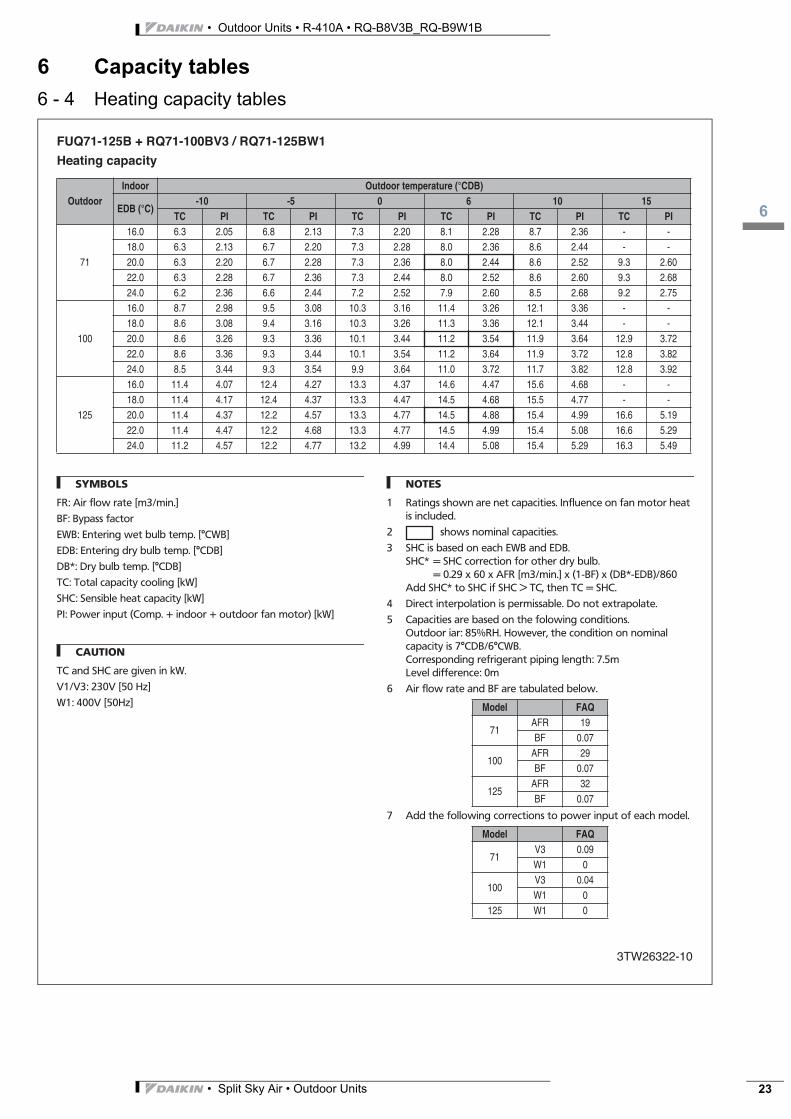
FUQ71-125B + RQ71-100BV3 / RQ71-125BW1
3TW26322-10
Heating capacity
SYMBOLS
FR: Air flow rate [m3/min.]
BF: Bypass factor
EWB: Entering wet bulb temp. [°CWB]
EDB: Entering dry bulb temp. [°CDB]
DB*: Dry bulb temp. [°CDB]
TC: Total capacity cooling [kW]
SHC: Sensible heat capacity [kW]
PI: Power input (Comp. + indoor + outdoor fan motor) [kW]
CAUTION
TC and SHC are given in kW.
V1/V3: 230V [50 Hz]
W1: 400V [50Hz]
NOTES
1 Ratings shown are net capacities. Influence on fan motor heat is included.
2 shows nominal capacities.
3 SHC is based on each EWB and EDB.SHC* = SHC correction for other dry bulb.
= 0.29 x 60 x AFR [m3/min.] x (1-BF) x (DB*-EDB)/860Add SHC* to SHC if SHC > TC, then TC = SHC.
4 Direct interpolation is permissable. Do not extrapolate.
5 Capacities are based on the folowing conditions.Outdoor iar: 85%RH. However, the condition on nominal capacity is 7°CDB/6°CWB.Corresponding refrigerant piping length: 7.5mLevel difference: 0m
6 Air flow rate and BF are tabulated below.
7 Add the following corrections to power input of each model.
OutdoorIndoor Outdoor temperature (°CDB)
EDB (°C)-10 -5 0 6 10 15
TC PI TC PI TC PI TC PI TC PI TC PI
71
16.0 6.3 2.05 6.8 2.13 7.3 2.20 8.1 2.28 8.7 2.36 - -18.0 6.3 2.13 6.7 2.20 7.3 2.28 8.0 2.36 8.6 2.44 - -20.0 6.3 2.20 6.7 2.28 7.3 2.36 8.0 2.44 8.6 2.52 9.3 2.6022.0 6.3 2.28 6.7 2.36 7.3 2.44 8.0 2.52 8.6 2.60 9.3 2.6824.0 6.2 2.36 6.6 2.44 7.2 2.52 7.9 2.60 8.5 2.68 9.2 2.75
100
16.0 8.7 2.98 9.5 3.08 10.3 3.16 11.4 3.26 12.1 3.36 - -18.0 8.6 3.08 9.4 3.16 10.3 3.26 11.3 3.36 12.1 3.44 - -20.0 8.6 3.26 9.3 3.36 10.1 3.44 11.2 3.54 11.9 3.64 12.9 3.7222.0 8.6 3.36 9.3 3.44 10.1 3.54 11.2 3.64 11.9 3.72 12.8 3.8224.0 8.5 3.44 9.3 3.54 9.9 3.64 11.0 3.72 11.7 3.82 12.8 3.92
125
16.0 11.4 4.07 12.4 4.27 13.3 4.37 14.6 4.47 15.6 4.68 - -18.0 11.4 4.17 12.4 4.37 13.3 4.47 14.5 4.68 15.5 4.77 - -20.0 11.4 4.37 12.2 4.57 13.3 4.77 14.5 4.88 15.4 4.99 16.6 5.1922.0 11.4 4.47 12.2 4.68 13.3 4.77 14.5 4.99 15.4 5.08 16.6 5.2924.0 11.2 4.57 12.2 4.77 13.2 4.99 14.4 5.08 15.4 5.29 16.3 5.49
Model FAQ
71AFR 19BF 0.07
100AFR 29BF 0.07
125AFR 32BF 0.07
Model FAQ
71V3 0.09W1 0
100V3 0.04W1 0
125 W1 0

• Outdoor Units • R-410A • RQ-B8V3B_RQ-B9W1B
6
• Split Sky Air • Outdoor Units24
6 Capacity tables6 - 4 Heating capacity tables
FDQ125B + RQ125BW1
3TW26322-12
Heating capacity
SYMBOLS
FR: Air flow rate [m3/min.]
BF: Bypass factor
EWB: Entering wet bulb temp. [°CWB]
EDB: Entering dry bulb temp. [°CDB]
DB*: Dry bulb temp. [°CDB]
TC: Total capacity cooling [kW]
SHC: Sensible heat capacity [kW]
PI: Power input (Comp. + indoor + outdoor fan motor) [kW]
CAUTION
TC and SHC are given in kW.
V1/V3: 230V [50 Hz]
W1: 400V [50Hz]
NOTES
1 Ratings shown are net capacities. Influence on fan motor heat is included.
2 shows nominal capacities.
3 SHC is based on each EWB and EDB.SHC* = SHC correction for other dry bulb.
= 0.29 x 60 x AFR [m3/min.] x (1-BF) x (DB*-EDB)/860Add SHC* to SHC if SHC > TC, then TC = SHC.
4 Direct interpolation is permissable. Do not extrapolate.
5 Capacities are based on the folowing conditions.Outdoor air: 85%RH. However, the condition on nominal capacity is 7°CDB/6°CWB.Corresponding refrigerant piping length: 7.5mLevel difference: 0m
6 Air flow rate and BF are tabulated below.
OutdoorIndoor Outdoor temperature (°CDB)
EDB (°C)-10 -5 0 6 10 15
TC PI TC PI TC PI TC PI TC PI TC PI
125
16.0 11.5 3.76 12.5 3.95 13.4 4.04 14.7 4.14 15.7 4.32 - -18.0 11.5 3.85 12.5 4.04 13.4 4.14 14.6 4.32 15.6 4.41 - -20.0 11.5 4.04 12.3 4.22 13.4 4.41 14.6 4.51 15.5 4.61 16.7 4.8022.0 11.5 4.14 12.3 4.32 13.4 4.41 14.6 4.61 15.5 4.70 16.7 4.8824.0 11.3 4.22 12.3 4.41 13.3 4.61 14.5 4.70 15.5 4.88 16.4 5.07
Model FAQ
125AFR 45BF 0.25

3
6
• Split Sky Air • Outdoor Units 25
• Outdoor Units • R-410A • RQ-B8V3B_RQ-B9W1B
6 Capacity tables6 - 4 Heating capacity tables
3TW26322-15
RR/RQ71∼125B
Capacity (%)
Field piping length (m)
Cooling
Heating
Capacity in function of field piping length for non-inverter

• Outdoor Units • R-410A • RQ-B8V3B_RQ-B9W1B
6
• Split Sky Air • Outdoor Units26
6 Capacity tables6 - 5 Heating capacity tables simultaneous operation
Simultaneous operation RQ71-100-125B
3TW26322-14
Heating capacity
SYMBOLS
EWB: Entering wet bulb temp. [°CWB]
EDB: Entering dry bulb temp. [°CDB]
TC: Total capacity heating [kW]
PI o: Power input of outdoor unit [kW]
PI corr1: Correction factor for PI depending on voltage of outdoor [kW]
PI corr2: Correction factor for PI depending used indoor units [kW]
PI: Total power input [kW]PI = PI o + PI corr1 + ∑ PI corr2e.g. RQ100B7V3B + FBQ71B7V3B + FHQ35BUV1BPI = 3.84 + 0.27 + 0.21 + 0.14 = 4.46 kW
NOTES
1 Ratings shown are net capacities which include a deduction for indoor fan motor heat.
2 shows nominal capacities.
3 Capacities are based on the folowing conditions.Corresponding refrigerant piping length: 7.5mLevel difference: 0mOutdoor air: 85% RHHowever, when outdoor air temperature is 7°CDB, wet bulb temperature is 6°CWB.
4 Direct interpolation is permissable. Do not extrapolate.
5 Add the following correction to the power input for the different outdoor units (PI corr1).
6 Add the following correction to the power input for each connected indoor unit (PI corr2).
7 The total capacity does not change with differrent combination of indoor units.
OutdoorIndoor Outdoor temperature (°CWB)
EDB (°C)-10 -5 0 6 10 15
TC PI TC PI TC PI TC PI TC PI TC PI
71
16.0 6.3 2.23 6.8 2.32 7.3 2.40 8.1 2.49 8.7 2.57 - -18.0 6.3 2.32 6.7 2.40 7.3 2.49 8.0 2.57 8.6 2.66 - -20.0 6.3 2.40 6.7 2.49 7.3 2.57 8.0 2.66 8.6 2.75 9.3 2.8322.0 6.3 2.49 6.7 2.57 7.3 2.66 8.0 2.75 8.6 2.83 9.3 2.9224.0 6.2 2.57 6.6 2.66 7.2 2.75 7.9 2.83 8.5 2.92 9.2 3.00
100
16.0 8.7 3.23 9.5 3.34 10.3 3.43 11.4 3.54 12.1 3.64 - -18.0 8.6 3.34 9.4 3.43 10.3 3.54 11.3 3.64 12.1 3.74 - -20.0 8.6 3.54 9.3 3.64 10.1 3.74 11.2 3.84 11.9 3.94 12.9 4.0422.0 8.6 3.64 9.3 3.74 10.1 3.84 11.2 3.94 11.9 4.04 12.8 4.1424.0 8.5 3.74 9.3 3.84 9.9 3.94 11.0 4.04 11.7 4.14 12.8 4.25
125
16.0 11.4 4.10 12.4 4.31 13.3 4.40 14.6 4.51 15.6 4.72 - -18.0 11.4 4.20 12.4 4.40 13.3 4.51 14.5 4.72 15.5 4.81 - -20.0 11.4 4.40 12.2 4.61 13.3 4.81 14.5 4.92 15.4 5.03 16.6 5.2322.0 11.4 4.51 12.2 4.72 13.3 4.81 14.5 5.03 15.4 5.12 16.6 5.3324.0 11.2 4.61 12.2 4.81 13.2 5.03 14.4 5.12 15.4 5.33 16.3 5.53
Outdoormodel
Power supplyV3 W1
RQ71 0.12 0RQ100 0.27 0
Indoormodel
Indoor typesFBQ FHQ FFQ FCQ FAQ FUQ
35 0.12 0.14 0.08 0.14 - -50 0.16 0.14 0.09 0.14 - -60 0.21 0.14 0.11 0.16 - -71 0.21 0.14 - 0.16 0.069 0.16

3
7
• Split Sky Air • Outdoor Units 27
• Outdoor Units • R-410A • RQ-B8V3B_RQ-B9W1B
7 Dimensional drawing & centre of gravity7 - 1 Dimensional drawing
RQ71B
3TW26324-1
hole for anchorbolt 4-M12
LEGEND
1 Gas pipe connection ø15.9 flare
2 Liquid pipe connection ø9.5 flare
3 Service port (in the unit)
4 Grounding terminal M5 (in switch box)
5 Refrigerant piping intake
6 Power supply wiring intake (knock out hole ø34)
7 Control wiring intake (knock out hole ø27)
8 Drain outlet
RQ100B
3TW26344-1
hole for anchorbolt 4-M12
LEGEND
1 Gas pipe connection ø15.9 flare
2 Liquid pipe connection ø9.5 flare
3 Service port (in the unit)
4 Grounding terminal M5 (in switch box)
5 Refrigerant piping intake
6 Power supply wiring intake (knock out hole ø34)
7 Control wiring intake (knock out hole ø27)
8 Drain outlet

• Outdoor Units • R-410A • RQ-B8V3B_RQ-B9W1B
7
• Split Sky Air • Outdoor Units28
7 Dimensional drawing & centre of gravity7 - 1 Dimensional drawing
RQ125BW1
3TW26364-1
hole for anchorbolt 4-M12
LEGEND
1 Gas pipe connection ø15.9 flare
2 Liquid pipe connection ø9.5 flare
3 Service port (in the unit)
4 Grounding terminal M5 (in switch box)
5 Refrigerant piping intake
6 Power supply wiring intake (knock out hole ø34)
7 Control wiring intake (knock out hole ø27)
8 Drain outlet

3
7
• Split Sky Air • Outdoor Units 29
• Outdoor Units • R-410A • RQ-B8V3B_RQ-B9W1B
7 Dimensional drawing & centre of gravity7 - 2 Centre of gravity
R(Q)(R)71B
3TW26329-5B
R(Q)(R)100B
3TW26349-5B

• Outdoor Units • R-410A • RQ-B8V3B_RQ-B9W1B
7
• Split Sky Air • Outdoor Units30
7 Dimensional drawing & centre of gravity7 - 2 Centre of gravity
R(Q)(R)125B
3TW26369-5B

3
8
• Split Sky Air • Outdoor Units 31
• Outdoor Units • R-410A • RQ-B8V3B_RQ-B9W1B
8 Piping diagram
RQ71-125B (pair)
3TW26325-1
NOTE
1 The pipes between the branch and the indoor units should have the same size as the indoor connections.
Heat exchanger
Filter
Indoor unit
Stop valve(with service port - 5/16” flare)
Field piping ø9,5C 1220T-0
Field piping ø15,9C 1220T-0
Service port5/16”
Heat exchanger
Compressor
Outdoor unit
Check valve Flexible connection Flare connection Screw connection Flange connection Pinched pipe Spinned pipe
One way valve
Muffler
High pressure switch
4-way valve
One way valve
Filter
Receiver
Solenoid valve Electronic expansion valve
Filter Low pressure switch
Capillary tube
One way valve One way valveFilter
One way valve
Service port5/16”
Strainer
RQ71-125B (twin)
3TW26325-2
NOTE
1 The pipes between the branch and the indoor units should have the same size as the indoor connections.
Heat exchanger
Filter
Indoor unit
Stop valve(with service port - 5/16” flare)
Field piping ø9,5C 1220T-0
Field piping ø15,9C 1220T-0
Service port5/16”
Heat exchanger
Compressor
Outdoor unit
Check valve Flexible connection Flare connection Screw connection Flange connection Pinched pipe Spinned pipe
One way valve
Muffler
High pressure switch
4-way valve
One way valve
Filter
Receiver
Solenoid valve Electronic expansion valve
Filter Low pressure switch
Capillary tube
One way valve One way valveFilter
One way valve
Service port5/16”
Strainer
HeatingCooling
Heat exchanger
Filter
Indoor unit
Field piping
Field piping
Field piping
Field piping

• Outdoor Units • R-410A • RQ-B8V3B_RQ-B9W1B
8
• Split Sky Air • Outdoor Units32
8 Piping diagram
RQ100-125B (triple)
3TW26345-3
-
NOTE
1 The pipes between the branch and the indoor units should have the same size as the indoor connections.
Heat exchanger
Heat exchanger
Filter
Filter
Field piping
Field piping
Indoor unit
Indoor unit
Field piping
Field piping
Branch pipe(option)
Stop valve(with service port - 5/16” flare)
Field piping ø9,5C 1220T-0
Field piping ø15,9C 1220T-0
Service port5/16”
Heat exchanger
Compressor
Outdoor unit
Check valve Flexible connection Flare connection Screw connection Flange connection Pinched pipe Spinned pipe
Filter
Heat exchanger
Indoor unit
Field piping
Field piping
One way valve
Muffler
High pressure switch
4-way valve
One way valve
Filter
Receiver
Solenoid valve Electronic expansion valve
Filter Low pressure switch
Capillary tube
One way valve One way valveFilter
One way valve
Service port5/16”
Strainer

3
9
• Split Sky Air • Outdoor Units 33
• Outdoor Units • R-410A • RQ-B8V3B_RQ-B9W1B
9 Wiring diagram9 - 1 Wiring diagram
RQ71-100BV3
2TW26326-1B
LEGEND
A1P Printed circuit boardBS1 Push button switch
(forced defrost-pump down)
C1 Capacitor (M1F)C3 Capacitor (M1C)DS1 Dip switchE1HC Crankcase heater
F1U Fuse (T6.3/250V)HAP Light emitting diode
(service monitor green)K1M Magnetic contactor
(M1C)K1R Magnetic relay (K1M)K2R Magnetic relay (Y2S)K3R Magnetic relay (E1HC)K4R Magnetic relay (Y1S)K5R, K6R,
K7R Magnetic relay (M1F)M1C Motor compressorM1F Motor fanPC Power circuitQ1DI Earth leakage breaker
(30 mA)Q1M Thermo switch (M1F)R1T Thermistor (Air)R2T Thermistor (Coil)R3T Thermistor (Discharge
pipe)RC Signal receiver circuitS1PH Pressure switch (high)S1PL Pressure switch (low)SD Safety devices inputT1A Current transformerTC Signal transmission
circuitX1M, X2M Terminal stripY1E Expansion valve
(electronic)Y1S 4-way valveY2S Solenoid valveCT Current transformer
NOTE
1 Confirm the method of setting the dip switch (DS1) by service manual. When the unit is shipped by factory all switches are set to be off.
Power supply1~50 Hz230V
indoor
Switch box (outdoor)
Position of compressor terminal
Wire entrance
Field wiring
Terminal
BLK: blackBLU: blueORG: orange
RED: redWHT: whiteYLW: yellow
LiveNeutralConnector
Protective earth (screw)Terminal
outdoor
71-100 class
RQ71-100BW1
2TW26336-1B
LEGEND
A1P Printed circuit boardBS1 Push button switch
(forced defrost-pump down)
C1 Capacitor (M1F)DS1 Dip switchE1HC Crankcase heaterF1U, F2U Fuse (T6.3/250V)HAP Light emitting diode
(service monitor green)
K1M Magnetic contactor (M1C)
K1R Magnetic relay (K1M)K2R Magnetic relay (Y2S)K3R Magnetic relay (E1HC)K4R Magnetic relay (Y1S)K5R, K6R,K7R Magnetic relay (M1F)M1C Motor compressorM1F Motor fanPC Power circuit
Q1DI Earth leakage breaker (30mA)
Q1M Thermo switch (M1F)Q1RP Phase reverse circuitR1T Thermistor (Air)R2T Thermistor (Coil)R3T Thermistor (Discharge
pipe)RC Signal receiver circuitS1PH Pressure switch (high)S1PL Pressure switch (low)SD Safety devices inputT1A Current transformer
TC Signal transmission circuit
X1M, X2M Terminal stripY1E Expansion valve
(electronic)Y1S 4-way valveY2S Solenoid valveCT Current transformer
NOTE
1 Confirm the method of setting the dip switch (DS1) by service manual. When the unit is shipped by factory all switches are set to be off.
Power supply3N~50 Hz400V
indoor
Switch box (outdoor)
Position of compressor terminal
Wire entrance
Field wiring
Terminal
BLK: blackBLU: blueORG: orange
RED: redWHT: whiteYLW: yellow
LiveNeutralConnectorProtective earth (screw)
Terminal
outdoor
71-100 class
Short circuit connector
• Outdoor Units • R-410A • RQ-B8V3B_RQ-B9W1B
9
• Split Sky Air • Outdoor Units34
9 Wiring diagram9 - 1 Wiring diagram
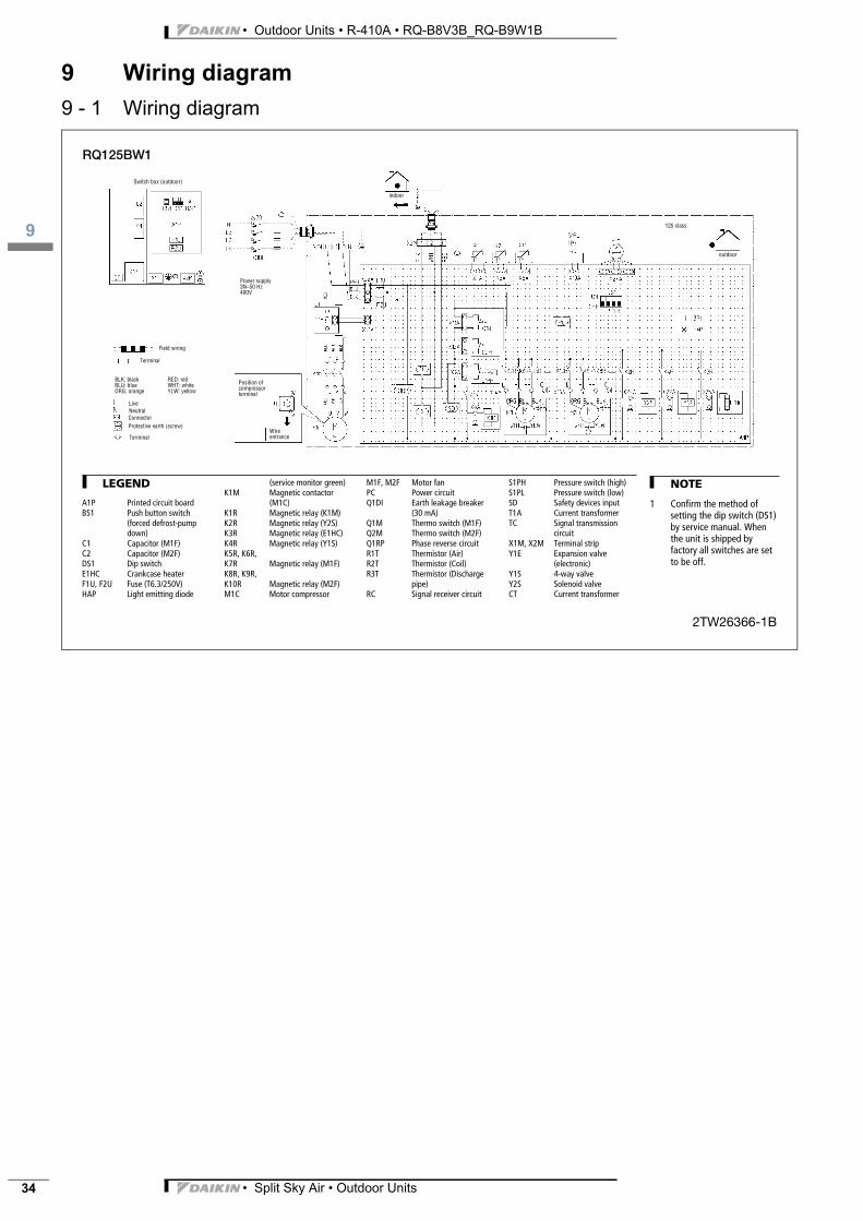
RQ125BW1
2TW26366-1B
LEGEND
A1P Printed circuit boardBS1 Push button switch
(forced defrost-pump down)
C1 Capacitor (M1F)C2 Capacitor (M2F)DS1 Dip switchE1HC Crankcase heaterF1U, F2U Fuse (T6.3/250V)HAP Light emitting diode
(service monitor green)K1M Magnetic contactor
(M1C)K1R Magnetic relay (K1M)K2R Magnetic relay (Y2S)K3R Magnetic relay (E1HC)K4R Magnetic relay (Y1S)K5R, K6R,K7R Magnetic relay (M1F)K8R, K9R,K10R Magnetic relay (M2F)M1C Motor compressor
M1F, M2F Motor fanPC Power circuitQ1DI Earth leakage breaker
(30 mA)Q1M Thermo switch (M1F)Q2M Thermo switch (M2F)Q1RP Phase reverse circuitR1T Thermistor (Air)R2T Thermistor (Coil)R3T Thermistor (Discharge
pipe)RC Signal receiver circuit
S1PH Pressure switch (high)S1PL Pressure switch (low)SD Safety devices inputT1A Current transformerTC Signal transmission
circuitX1M, X2M Terminal stripY1E Expansion valve
(electronic)Y1S 4-way valveY2S Solenoid valveCT Current transformer
NOTE
1 Confirm the method of setting the dip switch (DS1) by service manual. When the unit is shipped by factory all switches are set to be off.
Power supply3N~50 Hz400V
indoor
Switch box (outdoor)
Position of compressor terminal
Wire entrance
Field wiring
Terminal
BLK: blackBLU: blueORG: orange
RED: redWHT: whiteYLW: yellow
LiveNeutralConnectorProtective earth (screw)
Terminal
outdoor
125 class

3
9
• Split Sky Air • Outdoor Units 35
• Outdoor Units • R-410A • RQ-B8V3B_RQ-B9W1B
9 Wiring diagram9 - 2 External connection diagram
R(Q)(R)71-125B
4TW26329-7
I Pair
II Twin
III Triple
M Master
S Slave
1 Earth leak detector
2 Fuse
3 Remote controller

• Outdoor Units • R-410A • RQ-B8V3B_RQ-B9W1B
10
• Split Sky Air • Outdoor Units36
10 Sound data10 - 1 Sound pressure spectrum
RR/RQ71B Cooling
3TW26327-1
Octave band center frequency (Hz)
Soun
d op
erat
ion
leve
l (dB
)
Measuring location(discharge side)
NOTES
1 Data is valid at free field condition.2 Data is valid at nominal operation condition.3 dBA = A-weighted sound operation level (A-scale
according to IEC)4 Reference acoustic pressure 0dB = 20µPa.5 Curve for RQ71B and RR71B in cooling mode.
RQ71B Heating
3TW26327-2
NOTES
1 Data is valid at free field condition.2 Data is valid at nominal operation condition.3 dBA = A-weighted sound operation level (A-scale
according to IEC)4 Reference acoustic pressure 0dB = 20µPa.5 Curve for RQ71B in heating mode. Measuring location
(discharge side)
Octave band center frequency (Hz)So
und
oper
atio
n le
vel (
dB)
RR/RQ100B Cooling
3TW26347-1
Octave band center frequency (Hz)
Soun
d op
erat
ion
leve
l (dB
)
Measuring location(discharge side)
NOTES
1 Data is valid at free field condition.2 Data is valid at nominal operation condition.3 dBA = A-weighted sound operation level (A-scale
according to IEC)4 Reference acoustic pressure 0dB = 20µPa.5 Curve for RQ100B and RR100B in cooling mode.
RR/RQ100B Heating
3TW26347-2
Octave band center frequency (Hz)
Soun
d op
erat
ion
leve
l (dB
)
Measuring location(discharge side)
NOTES
1 Data is valid at free field condition.2 Data is valid at nominal operation condition.3 dBA = A-weighted sound operation level (A-scale
according to IEC)4 Reference acoustic pressure 0dB = 20µPa.5 Curve for RQ100B and RR100B in heating
mode.

3
10
• Split Sky Air • Outdoor Units 37
• Outdoor Units • R-410A • RQ-B8V3B_RQ-B9W1B
10 Sound data10 - 1 Sound pressure spectrum
RR/RQ125B Cooling
3TW26367-1
Octave band center frequency (Hz)
Soun
d op
erat
ion
leve
l (dB
)
NOTES
1 Data is valid at free field condition.2 Data is valid at nominal operation condition.3 dBA = A-weighted sound operation level (A-scale
according to IEC)4 Reference acoustic pressure 0dB = 20µPa.5 Curve for RQ125B and RR125B in cooling mode. Measuring location
(discharge side)
RQ125B Heating
3TW26367-2
Octave band center frequency (Hz)
Soun
d op
erat
ion
leve
l (dB
)
Measuring location(discharge side)
NOTES
1 Data is valid at free field condition.2 Data is valid at nominal operation condition.3 dBA = A-weighted sound operation level (A-scale
according to IEC)4 Reference acoustic pressure 0dB = 20µPa.5 Curve for RQ125B in heating mode.

• Outdoor Units • R-410A • RQ-B8V3B_RQ-B9W1B
10
• Split Sky Air • Outdoor Units38
10 Sound data10 - 2 Sound power spectrum
RR/RQ71B Cooling
3TW26327-3
Octave band center frequency (Hz)
Soun
d op
erat
ion
leve
l (dB
)
NOTE
1 Data is valid at free field condition.2 Data is valid at nominal operation condition.3 dBA = A-weighted sound operation level (A-scale according to IEC)4 Reference acoustic pressure 0dB = 20µPa.5 Curve for RQ100B and RR100B in cooling mode.
RR/RQ100B Cooling
3TW26347-3
Octave band center frequency (Hz)So
und
oper
atio
n le
vel (
dB)
NOTE
1 Data is valid at free field condition.2 Data is valid at nominal operation condition.3 dBA = A-weighted sound operation level (A-scale according to IEC)4 Reference acoustic pressure 0dB = 20µPa.5 Curve for RQ100B and RR100B in cooling mode.
RR/RQ125B Cooling
3TW26367-3
Octave band center frequency (Hz)
Soun
d op
erat
ion
leve
l (dB
)
NOTE
1 Data is valid at free field condition.2 Data is valid at nominal operation condition.3 dBA = A-weighted sound operation level (A-scale according to IEC)4 Reference acoustic pressure 0dB = 20µPa.5 Curve for RQ125B and RR125B in cooling mode.

3
11
• Split Sky Air • Outdoor Units 39
• Outdoor Units • R-410A • RQ-B8V3B_RQ-B9W1B
11 Operation range
RQ71-125B
3TW26323-1
Indoor temp. (°CDB)
Out
door
tem
p. (°
CD
B)
Indoor temp. (°CWB)
HEATING
COOLING
Out
door
tem
p. (°
CD
B)
Out
door
tem
p. (°
CD
B)
Out
door
tem
p. (°
CW
B)
Ope
ratio
n ra
nge
Allo
wab
le ra
nge
of o
pera
tion
(war
min
g up
)
.
NOTES
1 Model names:RQ71BV3RQ71BW1RQ100BV3RQ100BW1RQ125BW1
2 Depending on operation and installation conditions, the indoor unit can change over to freeze-up operation (indoor de-icing).
3 To reduce the freeze-up operation (indoor de-icing) frequency it is recommended to install the outdoor unit in a location not exposed to wind.

ISO14001 assures an effective environmental management system in order to help protect human•health•and the environment from the potential impact of our activities, products and services and to assist in maintaining and improving the quality of the•environment.
Daikin Europe N.V. is approved by LRQA for its Quality Management System in accordance with the ISO9001 standard. ISO9001 pertains to quality assurance regarding design, development, manufacturing as well as to services related to the product.
Daikin units comply with the Europeanregulations that guarantee the safety ofthe product.
Zandvoordestraat 300B-8400 Ostend - Belgiumwww.daikineurope.com EE
DE0
6-1/
3 •
05/2
006
Prep
ared
in B
elgi
um b
y La
nnoo
The present publication is drawn up by way of information only and does not constitute an offer binding upon Daikin Europe N.V.. Daikin Europe N.V. has compiled the content of this publication to the best of its knowledge. No express or implied warranty is given for the completeness, accuracy, reliability or fitness for particular purpose of its content and the products and services presented therein. Specifications are subject to change without prior notice. Daikin Europe N.V. explicitly rejects any liability for any direct or indirect damage, In the broadest sense, arising from or related to the use and/or interpretation of this publication. All content is copyrighted by Daikin Europe N.V..
ÉEEDE06-1/3ÇËÍ
Split - Sky Air
Daikin Europe N.V. is participating in the EUROVENT Certification Programme. Products are as listed in the EUROVENT Directory of Certified Products.
Recommended