MX17A-05-O17 10/09
EQUIPMENT:
PUBLICATION:
ISSUE No. & DATE:
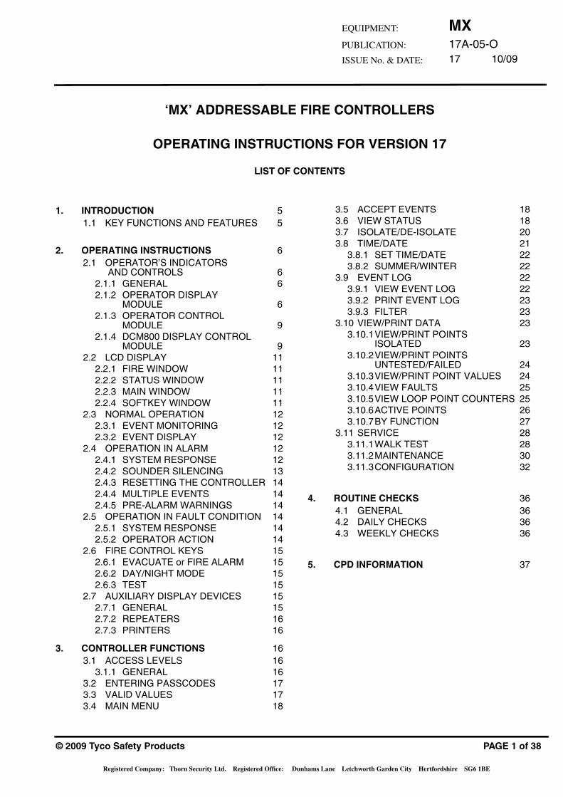
‘MX’ ADDRESSABLE FIRE CONTROLLERS
OPERATING INSTRUCTIONS FOR VERSION 17
LIST OF CONTENTS
1. INTRODUCTION 51.1 KEY FUNCTIONS AND FEATURES 5
2. OPERATING INSTRUCTIONS 62.1 OPERATOR’S INDICATORS
AND CONTROLS 62.1.1 GENERAL 62.1.2 OPERATOR DISPLAY
MODULE 62.1.3 OPERATOR CONTROL
MODULE 92.1.4 DCM800 DISPLAY CONTROL
MODULE 92.2 LCD DISPLAY 11
2.2.1 FIRE WINDOW 112.2.2 STATUS WINDOW 112.2.3 MAIN WINDOW 112.2.4 SOFTKEY WINDOW 11
2.3 NORMAL OPERATION 122.3.1 EVENT MONITORING 122.3.2 EVENT DISPLAY 12
2.4 OPERATION IN ALARM 122.4.1 SYSTEM RESPONSE 122.4.2 SOUNDER SILENCING 132.4.3 RESETTING THE CONTROLLER 142.4.4 MULTIPLE EVENTS 142.4.5 PRE-ALARM WARNINGS 14
2.5 OPERATION IN FAULT CONDITION 142.5.1 SYSTEM RESPONSE 142.5.2 OPERATOR ACTION 14
2.6 FIRE CONTROL KEYS 152.6.1 EVACUATE or FIRE ALARM 152.6.2 DAY/NIGHT MODE 152.6.3 TEST 15
2.7 AUXILIARY DISPLAY DEVICES 152.7.1 GENERAL 152.7.2 REPEATERS 162.7.3 PRINTERS 16
3. CONTROLLER FUNCTIONS 163.1 ACCESS LEVELS 16
3.1.1 GENERAL 163.2 ENTERING PASSCODES 173.3 VALID VALUES 173.4 MAIN MENU 18
© 2009 Tyco Safety Products
Registered Company: Thorn Security Ltd. Registered Office: Du
3.5 ACCEPT EVENTS 183.6 VIEW STATUS 183.7 ISOLATE/DE-ISOLATE 203.8 TIME/DATE 21
3.8.1 SET TIME/DATE 223.8.2 SUMMER/WINTER 22
3.9 EVENT LOG 223.9.1 VIEW EVENT LOG 223.9.2 PRINT EVENT LOG 233.9.3 FILTER 23
3.10 VIEW/PRINT DATA 233.10.1VIEW/PRINT POINTS
ISOLATED 233.10.2VIEW/PRINT POINTS
UNTESTED/FAILED 243.10.3VIEW/PRINT POINT VALUES 243.10.4VIEW FAULTS 253.10.5VIEW LOOP POINT COUNTERS 253.10.6ACTIVE POINTS 263.10.7BY FUNCTION 27
3.11 SERVICE 283.11.1WALK TEST 283.11.2MAINTENANCE 303.11.3CONFIGURATION 32
4. ROUTINE CHECKS 364.1 GENERAL 364.2 DAILY CHECKS 364.3 WEEKLY CHECKS 36
5. CPD INFORMATION 37
PAGE 1 of 38
nhams Lane Letchworth Garden City Hertfordshire SG6 1BE

MX17A-05-O17 10/09
This page intentionally left blank
PAGE 2 of 38
MX17A-05-O17 10/09
EQUIPMENT:
PUBLICATION:
ISSUE No. & DATE:
0
12
3
45
6
78
9
AB
CD
EF
GH
IJK
LM
NO
PQ
RS
TU
VW
XY
Z
Last Fire 002
General
Zone 030 B055
4th Floor
Washroom / Window
F1
F2
F3
F4
F5
View
More
Zone 002 B002
1st Floor Corridoor
Room 117
First Fire
Information
FIR
E
I
0
SIL
EN
CE
BU
ZZ
ER
RE
SE
TE
VA
CU
AT
ES
ILE
NC
E/
RE
SO
UN
D
DIS
AB
LED
FAU
LT
AC
TIV
ATE
D
AC
TIV
ATE
D
DIS
AB
LED
FAU
LT
AC
TIV
ATE
D
SY
ST
EM
FA
ULT
MA
INS
FA
ULT
PO
WE
R O
N
FAU
LT
DIS
AB
LE
D
TES
T
GE
NE
RA
LP
RO
TE
CT
ION
SO
UN
DE
RS
PAN
EL
SIG
NA
LL
ING
DA
YN
IGH
TIN
VE
ST
IGA
TE
DE
LA
Y
PO
WE
R F
AU
LT
DIS
AB
LED
FAU
LT
DA
Y M
OD
E
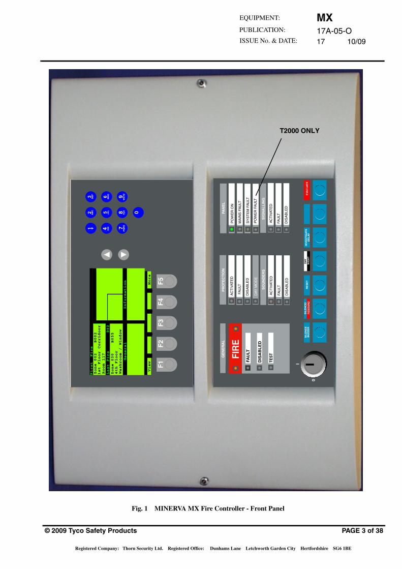
Fig. 1 MINERVA MX Fire Controller - Front Panel
T2000 ONLY
© 2009 Tyco Safety Products PAGE 3 of 38
Registered Company: Thorn Security Ltd. Registered Office: Dunhams Lane Letchworth Garden City Hertfordshire SG6 1BE
MX17A-05-O17 10/09
3DEF
7PQRS
F5F4F3F2F1
1*
2ABC
6MNO
9WXYZ
0
8TUV
5JKL
4GHI
FIREFAULT
DISABLED
TEST
PRE ALARM
DAY MODE
ACTIVATED
FAULT
DISABLED
ACTIVATED
FAULT
DISABLEDSTATUS 1
STATUS 2
GENERAL SOUNDERS
1
2
3
4
5
6
7
8
9
10
11
12
13
14
15
16
17
18
19
20
21
22
23
24
25
26
27
28
29
30
31
32
33
34
35
36
37
38
39
41
42
43
44
45
46
47
48
49
50
51
52
53
54
55
56
57
58
61
62
63
64
65
66
67
68
69
70
71
72
73
74
75
76
77
78
79
80
I
0
POWER ON
MAINS FAULT
SYSTEM FAULT
40 60
59
SILENCE BUZZER RESET INVESTIGATE
DELAY FUNCTION EVACUATESILENCE
RESOUND
DAY
NIGHT
GENERAL SYSTEM SOUNDERS SIGNALLING CONTROLLER
ZONE DISPLAY
1 - Accept Events2 - Actual Status3 - (De-) Isolate4 - Time / Date5 - Event Log6 - View/Prn Status7 - Service
9 - Test Buzzer, LED's Display
Alarm Count: 0021
SYSTEM
Wed, 01-Mar-08 14:15
Company Name
General
Back0000
Main menu
SounSIL
3DEF
7PQRS
F5F4F3F2F1
1*
2ABC
6MNO
9WXYZ
0
8TUV
5JKL
4GHI
FIREFAULT
DISABLED
TEST
ACTIVATED
FAULT
ACTIVATED
FAULT
DISABLED
ACTIVATED
FAULT
DISABLEDDISABLED
DAY MODE
GENERAL SOUNDERS
1
2
3
4
5
6
7
8
9
10
11
12
13
14
15
16
17
18
19
20
21
22
23
24
25
26
27
28
29
30
31
32
33
34
35
36
37
38
39
41
42
43
44
45
46
47
48
49
50
51
52
53
54
55
56
57
58
61
62
63
64
65
66
67
68
69
70
71
72
73
74
75
76
77
78
79
80
I
0
POWER ON
MAINS FAULT
SYSTEM FAULT
40 60
59
SILENCE BUZZER RESET INVESTIGATE
DELAY FUNCTION EVACUATESILENCE
RESOUND
DAY
NIGHT
GENERAL PROTECTION SOUNDERS SIGNALLING PANEL
ZONE DISPLAY
ALPHANUMERICKEYPAD
SCROLLUP
SCROLLDOWN
SOFTKEYS
1 - Accept Events2 - View Status3 - Isolate/De-Isol4 - Time / Date5 - Event Log6 - View/Print Data7 - Service8 - Configuration9 - Test Buzzer, LED's Display
Alarm Count: 0021
SYSTEM
Wed, 01-Mar-08 14:15
Company Name
General
Back
Main menu
SYSTEM
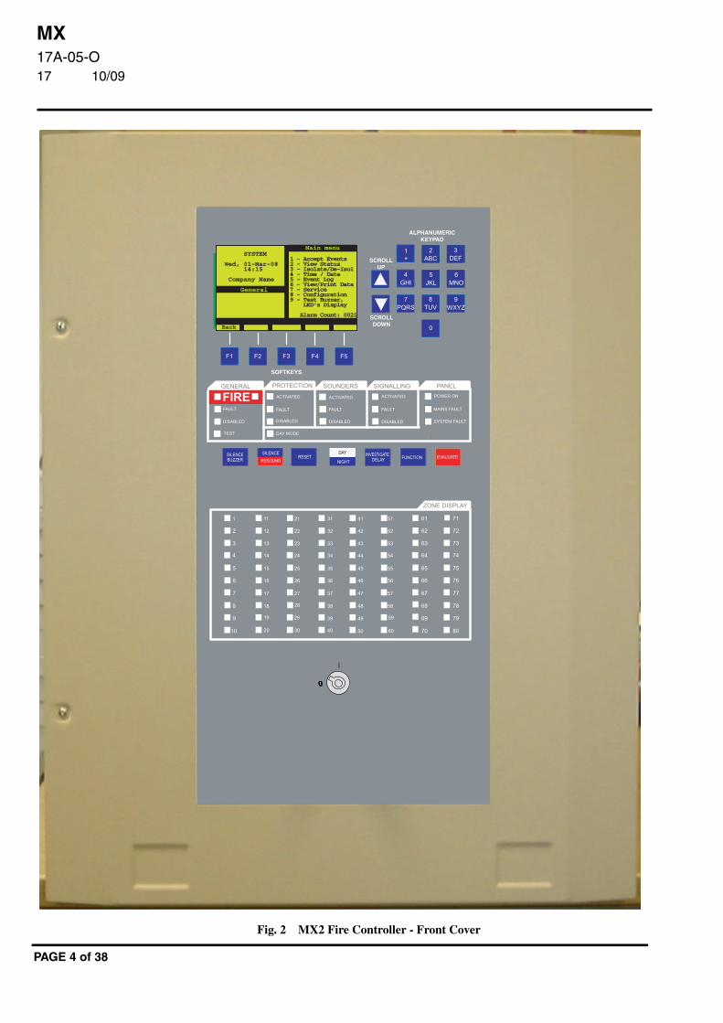
Fig. 2 MX2 Fire Controller - Front Cover
PAGE 4 of 38
MX17A-05-O17 10/09
EQUIPMENT:
PUBLICATION:
ISSUE No. & DATE:
1. INTRODUCTIONThe instructions given in this document are common to allthe ‘MX’ range of fire controllers, any differences beingoutlined as appropriate This document is written forFirmware Version 17.
The MINERVA MX range, form a comprehensive andcompatible range of modular and flexible EN54 approved(the MX2 and MX Black Box Panel are additional MXcompatible units which are fully EN54 : Part. 2 and Part. 4compliant) addressable fire controllers using Tyco MZXTechnologyTM.
Standard MINERVA MX fire controllers include:
• MX1000 – 250 point,16/32/ 40/80/120/160/200 or 240 zone network capable firecontroller – 1 loop controller in compactdesigner housing.
• MX4000 – 1000 point, 16/32/40/80/120/160/200 or 240 zone network capable firecontroller - 2 to 8 loop controller in compactdesigner housing.
• T2000 – 1000 point, 16/32/40/80/120/160/200 or 240 zone network capable firecontroller - 2 to 8 loop controller in Marineapproved compact housing.
• MXR – Fully functional repeater in compactdesigner housing.
• T2000 Marine Full Function Repeater.
• MX2-100 - 250 point, 16/32/40/80/160/200or 240 zone network capable fire C.I.E. – 1loop C.I.E. in housing with integral backupbatteries.
• MX2-200 - 1000 point, 16/32/40/80/160/200or 240 zone network capable fire C.I.E. - 2 to8 loop C.I.E. in housing with integral backupbatteries.
All variants fully comply with the requirements of EN54parts 2 and 4 and may be installed in a system whichcomplies with the requirements of BS 5839 : Part 1. TheMarine versions also comply with the requirements ofS.O.L.A.S. and marine Classification Societies.
1.1 KEY FUNCTIONS AND FEATURES
All MINERVA MX controllers are built around commonhardware and software modules incorporating the followingcommon functions and features:
• An integral 110-250V ac battery backedpower supply providing 24V dc (nominal) atup to 5A (alarm load) for poweringconventional detection zone interfaces(DIM800/DDM800), conventional soundersand beacons, door release mechanisms andinterface relays and remote full functionrepeaters.
© 2009 Tyco Safety Products
Registered Company: Thorn Security Ltd. Registered Office: Du
• Power supply incorporates a 24V DCcharger capable of charging up to 38Ahbatteries to provide up to 72 hours backupand 30 minutes in alarm (BS 5839 : Part 1) or90 hours backup and 15 minutes in alarm.
• Full EN54 compliant control switches andindicators with keyswitch enable andoptional programmable LED indicators andcontrol switches.
• Large backlit 16 line x 40 character LCDdisplay with detailed and preciseidentification of all sectors, zones and points,comprehensive 95 character emergencyprocedure instructions and full system statusindication including counters of number ofpoints in alarm, fault, disabled and testmode.
• Extensive menu driven and passwordcontrolled operator and engineer functionsincluding extensive isolate, override, test,service and diagnostic functions.
• System manager and engineer functionsincluding editing of point descriptions andviewing/printing of point values includingCO levels, temperatures and detectorobscuration levels.
• Optional self-test and verification ofdetectors from the controller.
• Peer-to-peer communication with up to 98other controllers providing a seamlessoperator interface to all other relevantdefined controllers on the network.
• Event log for logging of up to 3000 eventswhich can be viewed, selected and printed.
• Constant monitoring of all detectors andinput circuits and processing of detectorsensor information using standard, CCO andFastLogic fuzzy logic algorithms.
• Long term averaging and conditionmonitoring of smoke detectors with dirtydetector identification.
• Automatic or manual switching of detectormodes and sensitivities according to changesin occupancy patterns (day mode) andvariations in fire risk.
• Constant fault monitoring of all hardwarecomponents, power supplies, batteries,relays, sounder and speaker circuits,addressable loops, detectors and addressabledevices, monitored input circuits, remoteand local communication links.
• Communication with up to 1000 addresseson up to 8 detection loops per controller anda combination of up to 1500 auxiliary I/O,controller plus 7 full function repeaters andmultiple remote printers.
PAGE 5 of 38
nhams Lane Letchworth Garden City Hertfordshire SG6 1BE
MX17A-05-O17 10/09
• Signalling, supervision, status and faultindication of central station alarm signallingequipment such as BT Redcare STU.
• Option for one repeater to be provided from aremote PC computer using MX-Remoteservice and diagnostics software over thepublic switched telephone network (PSTN).
• Default cause and effect providing computercontrol of all outputs, sounders, beacons andspeakers in the event of alarm conditions.
• Powerful programmable cause and effectusing the flexible and easily configuredMINERVA group based event/actionprogramming language.
• Synchronisation and multiple output pulsepatterns for phased evacuation of up to 240zones using “Bell Mapping”.
• Arrangement of points in up to 240 detectionzones per controller.
2. OPERATING INSTRUCTIONS
2.1 OPERATOR’S INDICATORS AND CONTROLS
2.1.1 GENERAL
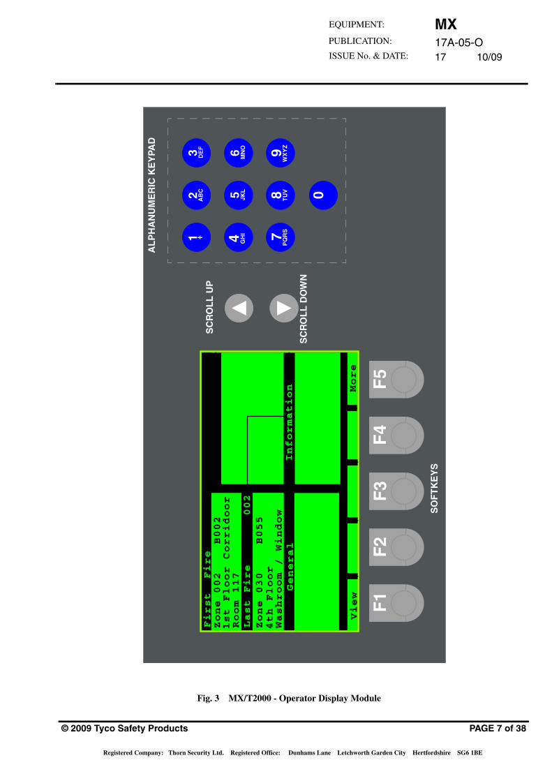
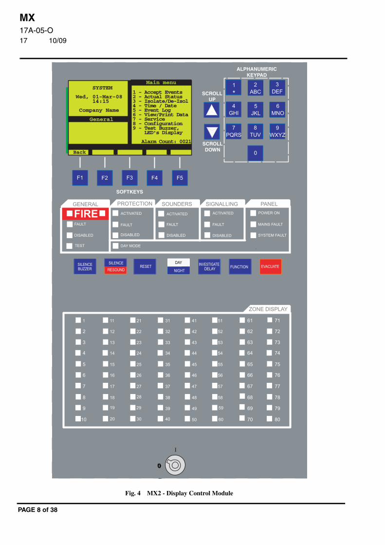
ALL operator controls and indicators are mounted on the frontpanel. For the MX/T2000, these are provided by the OperatorDisplay Module (ODM800 - top module) and the OperatorControl Module (OCM800 - bottom module). The ODMcontains the alphanumeric LCD display, keypad and‘Softkeys’. The OCM contains the ‘ENABLE KEY’,indicator LEDs and control keys.
For MX2 systems all operator controls and indicators exceptthe ‘ENABLE KEY’ are provided by the Display ControlModule (DCM800). The ‘ENABLE KEY’ is providedseparately at the bottom of the front panel.
2.1.2 OPERATOR DISPLAY MODULE
The Operator Display Module (Fig. 3) contains the followingindicators and controls:
• A 640 character backlit LCD alphanumericdisplay, arranged in 16 rows of 40 characters.This is used to display information about thesystem status and alarms. The backlight is onwhen the keyswitch is set to the ‘enable’position, when a key is pressed or when anAlarm or Fault is present.
• Switches F1 to F5 - used to carry out thefunctions displayed on the bottom line of theLCD display.
• An alphanumeric keypad used for enteringaccess codes, text strings or generalinformation as follows:
PAGE 6 of 38
• SCROLL UP and SCROLL DOWN keys -used to scroll through a display or log oneentry at a time. These keys will auto-repeatif held down, ie, will scroll continuously.
• When used in conjunction with theConfiguration menu, the UP key switchesto upper case and the DOWN key to lowercase.
7PQRS
8TUV
9WXYZ
6MNO
5JKL
4GHI
3DEF
2ABC
0
1
Used to enter the number 0
Used to enter the number 1 or specialsymbols
Used to enter the number 2 or letters ‘A’,‘B’ or ‘C’
Used to enter the number 3 or letters ‘D’,‘E’ or ‘F’
Used to enter the number 4 or letters ‘G’,‘H’ or ‘I’
Used to enter the number 5 or letters ‘J’,‘K’ or ‘L’
Used to enter the number 6 or letters ‘M’,‘N’ or ‘O’
Used to enter the number 7 or letters ‘P’,‘Q’, ‘R’ or ‘S’
Used to enter the number 8 or letters ‘T’,‘U’ or ‘V’
Used to enter the number 9 or letters ‘W’,‘X’, ‘Y’ or ‘Z’
MX17A-05-O17 10/09
EQUIPMENT:
PUBLICATION:
ISSUE No. & DATE:
0
12
3
45
6
78
9
AB
CD
EF
GH
IJK
LM
NO
PQ
RS
TU
VW
XY
Z
First Fire
Last Fire 002
General
Zone 002 B002
1st Floor Corridoor
Room 117
Zone 030 B055
4th Floor
Washroom / Window
F1
F2
F3
F4
F5
View
More
Information
Fig. 3 MX/T2000 - Operator Display Module
SO
FT
KE
YS
SC
RO
LL
UP
SC
RO
LL
DO
WN
AL
PH
AN
UM
ER
IC K
EY
PAD
© 2009 Tyco Safety Products PAGE 7 of 38
Registered Company: Thorn Security Ltd. Registered Office: Dunhams Lane Letchworth Garden City Hertfordshire SG6 1BE
MX17A-05-O17 10/09
3DEF
7PQRS
F5F4F3F2F1
1*
2ABC
6MNO
9WXYZ
0
8TUV
5JKL
4GHI
FIREFAULT
DISABLED
TEST
PRE ALARM
DAY MODE
ACTIVATED
FAULT
DISABLED
ACTIVATED
FAULT
DISABLEDSTATUS 1
STATUS 2
GENERAL SOUNDERS
1
2
3
4
5
6
7
8
9
10
11
12
13
14
15
16
17
18
19
20
21
22
23
24
25
26
27
28
29
30
31
32
33
34
35
36
37
38
39
41
42
43
44
45
46
47
48
49
50
51
52
53
54
55
56
57
58
61
62
63
64
65
66
67
68
69
70
71
72
73
74
75
76
77
78
79
80
I
0
POWER ON
MAINS FAULT
SYSTEM FAULT
40 60
59
SILENCE BUZZER RESET INVESTIGATE
DELAY FUNCTION EVACUATESILENCE
RESOUND
DAY
NIGHT
GENERAL SYSTEM SOUNDERS SIGNALLING CONTROLLER
ZONE DISPLAY
1 - Accept Events2 - Actual Status3 - (De-) Isolate4 - Time / Date5 - Event Log6 - View/Prn Sta7 - Service
9 - Test Buzzer, LED's Display
Alarm Count: 0021
SYSTEM
Wed, 01-Mar-08 14:15
Company Name
General
Back0000
Main menu
SounSIL
3DEF
7PQRS
F5F4F3F2F1
1*
2ABC
6MNO
9WXYZ
0
8TUV
5JKL
4GHI
FIREFAULT
DISABLED
TEST
ACTIVATED
FAULT
ACTIVATED
FAULT
DISABLED
ACTIVATED
FAULT
DISABLEDDISABLED
DAY MODE
GENERAL SOUNDERS
1
2
3
4
5
6
7
8
9
10
11
12
13
14
15
16
17
18
19
20
21
22
23
24
25
26
27
28
29
30
31
32
33
34
35
36
37
38
39
41
42
43
44
45
46
47
48
49
50
51
52
53
54
55
56
57
58
61
62
63
64
65
66
67
68
69
70
71
72
73
74
75
76
77
78
79
80
I
0
POWER ON
MAINS FAULT
SYSTEM FAULT
40 60
59
SILENCE BUZZER RESET INVESTIGATE
DELAY FUNCTION EVACUATESILENCE
RESOUND
DAY
NIGHT
GENERAL PROTECTION SOUNDERS SIGNALLING PANEL
ZONE DISPLAY
ALPHANUMERICKEYPAD
SCROLLUP
SCROLLDOWN
SOFTKEYS
1 - Accept Events2 - Actual Status3 - Isolate/De-Isol4 - Time / Date5 - Event Log6 - View/Print Data7 - Service8 - Configuration9 - Test Buzzer, LED's Display
Alarm Count: 0021
SYSTEM
Wed, 01-Mar-08 14:15
Company Name
General
Back
Main menu
SYSTEM
Fig. 4 MX2 - Display Control Module
PAGE 8 of 38
MX17A-05-O17 10/09
EQUIPMENT:
PUBLICATION:
ISSUE No. & DATE:
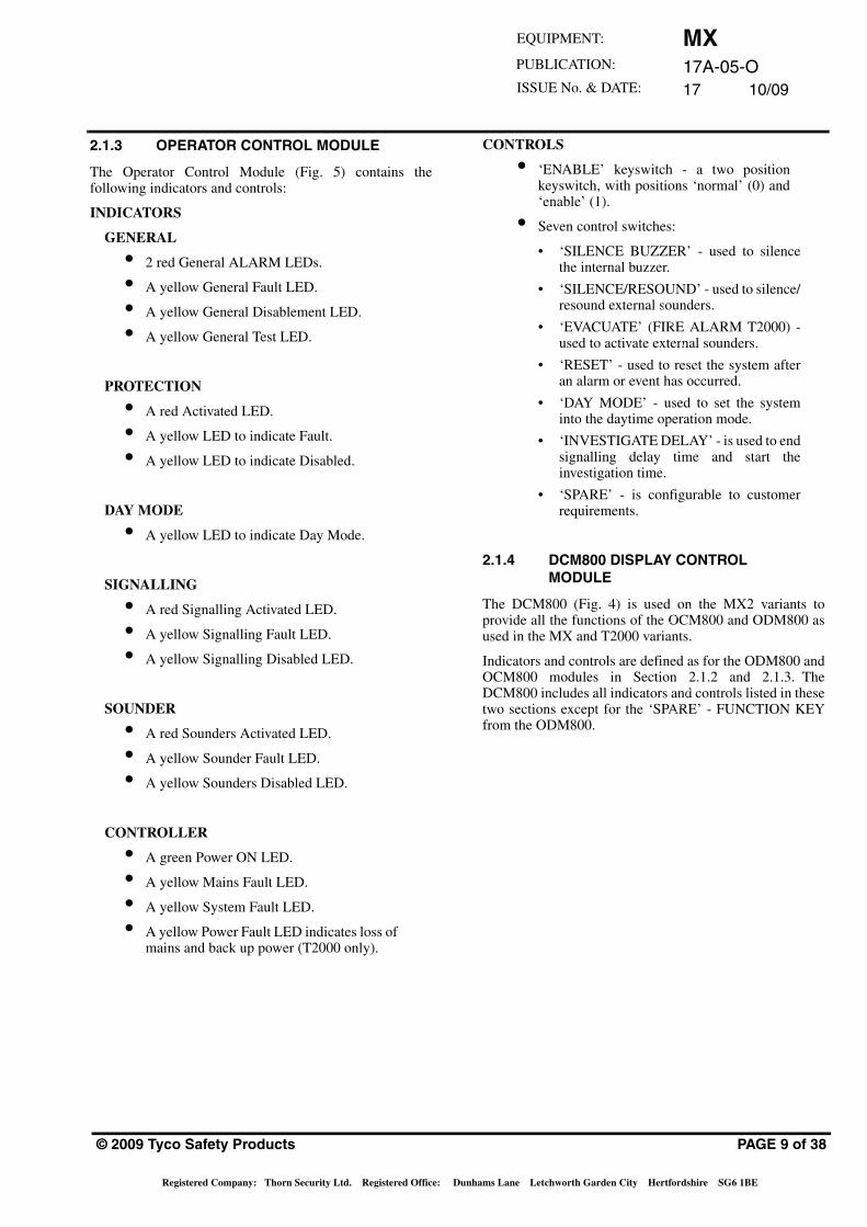
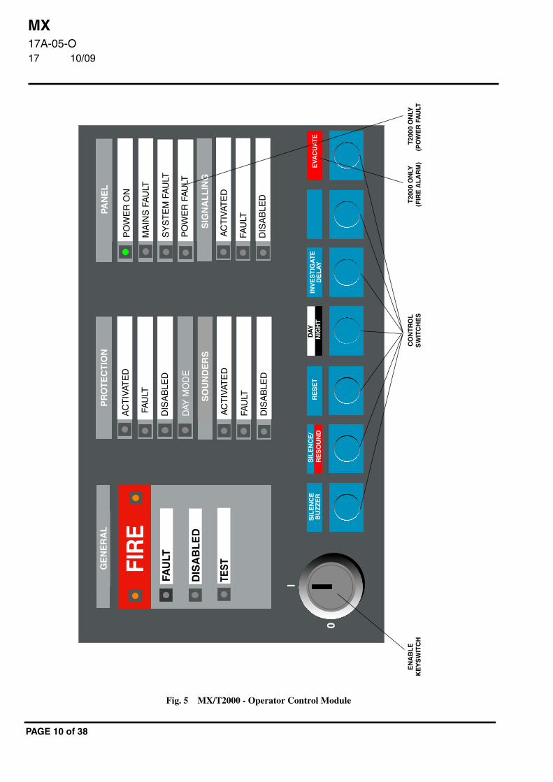
2.1.3 OPERATOR CONTROL MODULE
The Operator Control Module (Fig. 5) contains thefollowing indicators and controls:
INDICATORS
GENERAL
• 2 red General ALARM LEDs.
• A yellow General Fault LED.
• A yellow General Disablement LED.
• A yellow General Test LED.
PROTECTION
• A red Activated LED.
• A yellow LED to indicate Fault.
• A yellow LED to indicate Disabled.
DAY MODE
• A yellow LED to indicate Day Mode.
SIGNALLING
• A red Signalling Activated LED.
• A yellow Signalling Fault LED.
• A yellow Signalling Disabled LED.
SOUNDER
• A red Sounders Activated LED.
• A yellow Sounder Fault LED.
• A yellow Sounders Disabled LED.
CONTROLLER
• A green Power ON LED.
• A yellow Mains Fault LED.
• A yellow System Fault LED.
• A yellow Power Fault LED indicates loss ofmains and back up power (T2000 only).
© 2009 Tyco Safety Products
Registered Company: Thorn Security Ltd. Registered Office: Dun
CONTROLS
• ‘ENABLE’ keyswitch - a two positionkeyswitch, with positions ‘normal’ (0) and‘enable’ (1).
• Seven control switches:
• ‘SILENCE BUZZER’ - used to silencethe internal buzzer.
• ‘SILENCE/RESOUND’ - used to silence/resound external sounders.
• ‘EVACUATE’ (FIRE ALARM T2000) -used to activate external sounders.
• ‘RESET’ - used to reset the system afteran alarm or event has occurred.
• ‘DAY MODE’ - used to set the systeminto the daytime operation mode.
• ‘INVESTIGATE DELAY’ - is used to endsignalling delay time and start theinvestigation time.
• ‘SPARE’ - is configurable to customerrequirements.
2.1.4 DCM800 DISPLAY CONTROLMODULE
The DCM800 (Fig. 4) is used on the MX2 variants toprovide all the functions of the OCM800 and ODM800 asused in the MX and T2000 variants.
Indicators and controls are defined as for the ODM800 andOCM800 modules in Section 2.1.2 and 2.1.3. TheDCM800 includes all indicators and controls listed in thesetwo sections except for the ‘SPARE’ - FUNCTION KEYfrom the ODM800.
PAGE 9 of 38
hams Lane Letchworth Garden City Hertfordshire SG6 1BE
MX17A-05-O17 10/09
FIR
E
I
0
SIL
EN
CE
BU
ZZ
ER
RE
SE
TE
VAC
UA
TE
SIL
EN
CE
/R
ES
OU
ND
DIS
AB
LED
FAU
LT
AC
TIV
ATE
D
AC
TIV
ATE
D
DIS
AB
LED
FAU
LT
AC
TIV
ATE
D
SY
ST
EM
FA
ULT
MA
INS
FA
ULT
PO
WE
R O
N
FAU
LT
DIS
AB
LE
D
TESTG
EN
ER
AL
PR
OT
EC
TIO
N
SO
UN
DE
RS
PAN
EL
SIG
NA
LL
ING
DA
YN
IGH
TIN
VE
ST
IGA
TE
DE
LA
Y
PO
WE
R F
AU
LT
DIS
AB
LED
FAU
LT
EN
AB
LE
KE
YS
WIT
CH
CO
NT
RO
LS
WIT
CH
ES
T20
00 O
NLY
(PO
WE
R F
AU
LTT
2000
ON
LY(F
IRE
AL
AR
M)
DAY
MO
DE
Fig. 5 MX/T2000 - Operator Control Module
PAGE 10 of 38
MX17A-05-O17 10/09
EQUIPMENT:
PUBLICATION:
ISSUE No. & DATE:
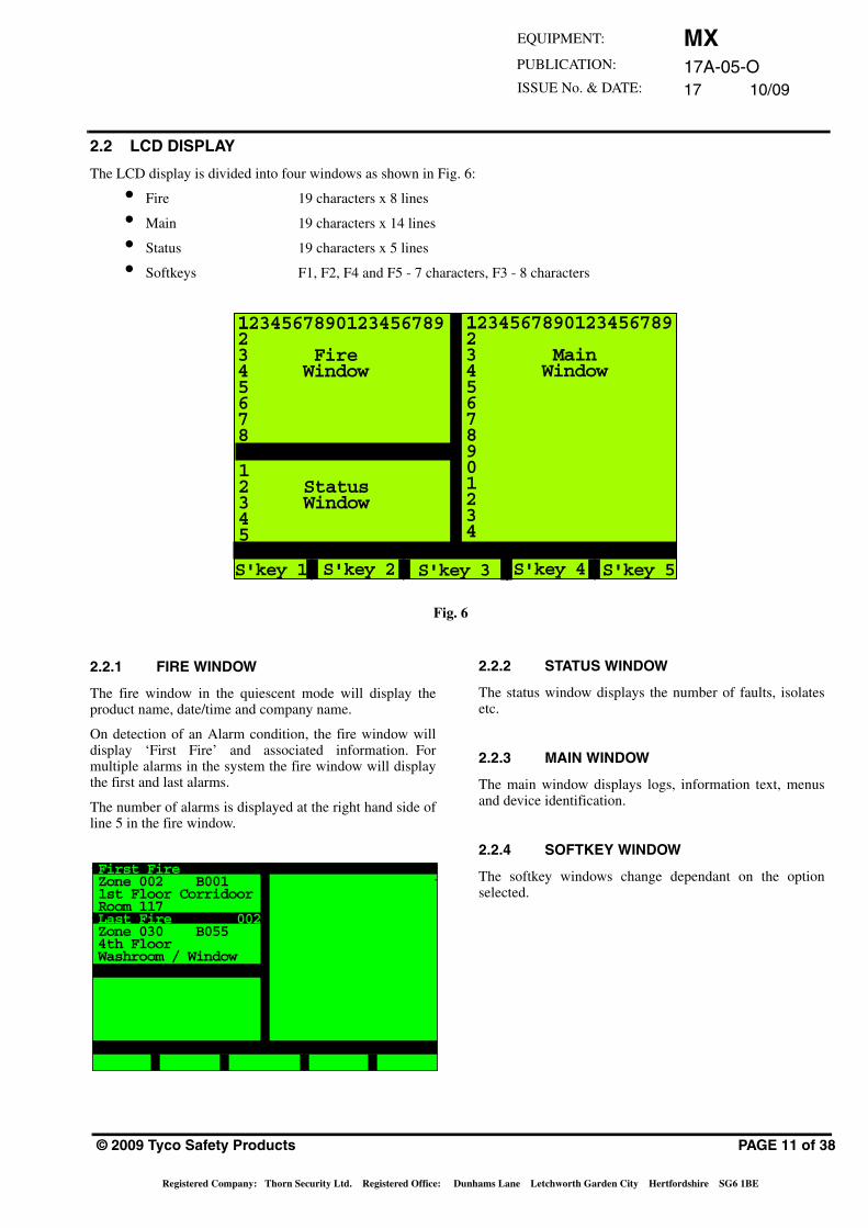
2.2 LCD DISPLAY
The LCD display is divided into four windows as shown in Fig. 6:
• Fire 19 characters x 8 lines
• Main 19 characters x 14 lines
• Status 19 characters x 5 lines
• Softkeys F1, F2, F4 and F5 - 7 characters, F3 - 8 characters
1234567890123456789 1234567890123456789123 Main4 Window5678901234
123 Fire4 Window5678
12 Status3 Window45
S'key 1 S'key 2 S'key 3 S'key 4 S'key 5
Fig. 6
2.2.1 FIRE WINDOW
The fire window in the quiescent mode will display theproduct name, date/time and company name.
On detection of an Alarm condition, the fire window willdisplay ‘First Fire’ and associated information. Formultiple alarms in the system the fire window will displaythe first and last alarms.
The number of alarms is displayed at the right hand side ofline 5 in the fire window.
First FireZone 002 B0011st Floor CorridoorRoom 117Last Fire 002Zone 030 B055 4th Floor Washroom / Window
© 2009 Tyco Safety Products
Registered Company: Thorn Security Ltd. Registered Office: Du
2.2.2 STATUS WINDOW
The status window displays the number of faults, isolatesetc.
2.2.3 MAIN WINDOW
The main window displays logs, information text, menusand device identification.
2.2.4 SOFTKEY WINDOW
The softkey windows change dependant on the optionselected.
PAGE 11 of 38
nhams Lane Letchworth Garden City Hertfordshire SG6 1BE
MX17A-05-O17 10/09
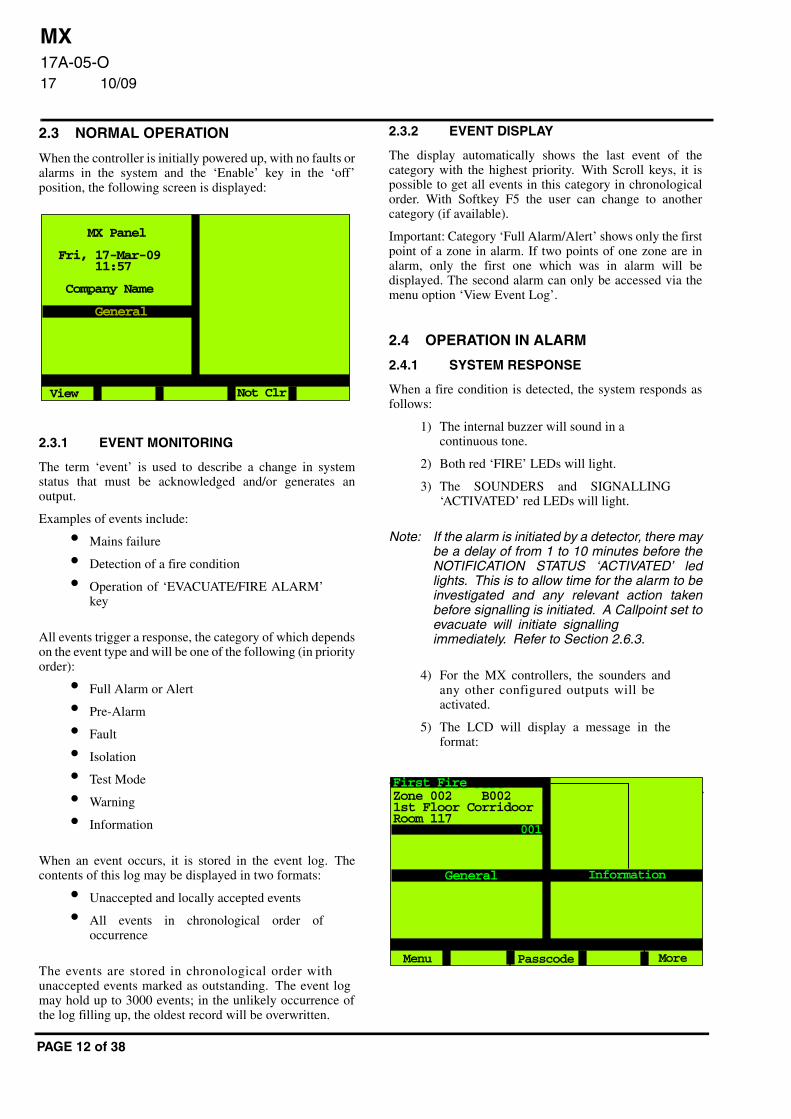
2.3 NORMAL OPERATION
When the controller is initially powered up, with no faults oralarms in the system and the ‘Enable’ key in the ‘off’position, the following screen is displayed:
2.3.1 EVENT MONITORING
The term ‘event’ is used to describe a change in systemstatus that must be acknowledged and/or generates anoutput.
Examples of events include:
• Mains failure
• Detection of a fire condition
• Operation of ‘EVACUATE/FIRE ALARM’key
All events trigger a response, the category of which dependson the event type and will be one of the following (in priorityorder):
• Full Alarm or Alert
• Pre-Alarm
• Fault
• Isolation
• Test Mode
• Warning
• Information
When an event occurs, it is stored in the event log. Thecontents of this log may be displayed in two formats:
• Unaccepted and locally accepted events
• All events in chronological order ofoccurrence
The events are stored in chronological order withunaccepted events marked as outstanding. The event logmay hold up to 3000 events; in the unlikely occurrence ofthe log filling up, the oldest record will be overwritten.
MX Panel
Fri, 17-Mar-09 11:57
Company Name
General
View Not Clr
PAGE 12 of 38
2.3.2 EVENT DISPLAY
The display automatically shows the last event of thecategory with the highest priority. With Scroll keys, it ispossible to get all events in this category in chronologicalorder. With Softkey F5 the user can change to anothercategory (if available).
Important: Category ‘Full Alarm/Alert’ shows only the firstpoint of a zone in alarm. If two points of one zone are inalarm, only the first one which was in alarm will bedisplayed. The second alarm can only be accessed via themenu option ‘View Event Log’.
2.4 OPERATION IN ALARM
2.4.1 SYSTEM RESPONSE
When a fire condition is detected, the system responds asfollows:
1) The internal buzzer will sound in acontinuous tone.
2) Both red ‘FIRE’ LEDs will light.
3) The SOUNDERS and SIGNALLING‘ACTIVATED’ red LEDs will light.
Note: If the alarm is initiated by a detector, there maybe a delay of from 1 to 10 minutes before theNOTIFICATION STATUS ‘ACTIVATED’ ledlights. This is to allow time for the alarm to beinvestigated and any relevant action takenbefore signalling is initiated. A Callpoint set toevacuate will initiate signallingimmediately. Refer to Section 2.6.3.
4) For the MX controllers, the sounders andany other configured outputs will beactivated.
5) The LCD will display a message in theformat:
First FireZone 002 B0021st Floor CorridoorRoom 117
General
Menu
First Fire
Passcode More
001
Information
MX17A-05-O17 10/09
EQUIPMENT:
PUBLICATION:
ISSUE No. & DATE:
6) For a T2000 controller, the sounders and anyother configured outputs will beactivated. If the alarm is not acceptedwithin the programmed delay period bypressing the ‘INVESTIGATE DELAY’ key,all other sounder outputs will be activated.
The message format is as follows:
Under ‘FIRE’:
The top line shows the Zone and Point number of thedevice in alarm.
The second line shows the zone description (defined atconfiguration).
The third line shows the point description (defined atconfiguration).
The fourth line shows the type of alarm.
If no information text is shown:
The fifth line shows date and time.The sixth line shows the device type.
The seventh line shows the actual CURRENTtemperature (if heat sensor).
Note: The above is only displayed if Extended AlarmInformation has been selected atconfiguration.
Under ‘First Fire’:
The first three lines from ‘FIRE’ arerepeated.The number of alarms is displayed on theblack bar underneath the first fireinformation.
2.4.2 SOUNDER SILENCING
When a FIRE ALARM is received, investigate the cause ofthe alarm.
WARNING:
WHEN SEARCHING AN AREA FOR THE SOURCE OF A FIRE ALARM SIGNAL,
WHERE A FIRE ALARM HAS BEEN INITIATED BY A ‘CARBON MONOXIDE’
FIRE DETECTOR, IT MUST BE REMEMBERED THAT A CARBON MONOXIDE FIRE DETECTOR MAY
GENERATE AN ALARM BEFORE OTHER FIRE INDICATORS (SUCH AS SMOKE) ARE
PRESENT.
© 2009 Tyco Safety Products
Registered Company: Thorn Security Ltd. Registered Office: Du
THIS OCCURS MOST NOTABLY IN DEEP SEATED FIRES IN DENSELY PACKED
MATERIALS, AREAS WHERE FIRES MAY OCCUR IN CUPBOARDS AND
STOREROOMS REMOTE FROM DETECTORS AND WHERE SMOKE
IMPERVIOUS BARRIERS EXIST BETWEEN THE SEAT OF THE FIRE AND THE
DETECTOR (SUCH AS WITHIN WALL CAVITIES). THESE FACTORS SHOULD BE
CONSIDERED CAREFULLY BEFORE DECLARING SAFE ANY AREA WHERE A CARBON MONOXIDE FIRE DETECTOR
HAS RAISED AN ALARM.
Once the cause of the alarm has been determined and allappropriate action has been taken, silence the sounders asfollows:
a) Insert the key into the front panel keyswitchand turn it clockwise to the ‘enable’position.
b) Press ‘SILENCE/RESOUND’.
The system will respond as follows:
i) The sounders will be silenced.
ii) The ‘SOUNDER ACTIVATED’ LED willextinguish.
iii) All other outputs will remain activated.
iv) The LCD display will remain showing thetype of alarm and the full zoneidentification. The ‘GENERAL’ displaywindow will show ‘Sound SIL’.
If it is required to manually resound the sounders, pressingthe ‘SILENCE/RESOUND’ key will reactivate thesounders.
PAGE 13 of 38
nhams Lane Letchworth Garden City Hertfordshire SG6 1BE
MX17A-05-O17 10/09
2.4.3 RESETTING THE CONTROLLER
Note:
1) When the system is in a Fire Alarm state,Silence must be operated before Reset ispossible. This interlock is always presentunder Fire Alarm condition, even if all soundersare isolated.
2) The controller should also NOT be reset untilthe source of the alarm has been determinedby the Fire Brigade or the cause otherwisefound (and the condition removed).
Once the notes above have been observed, press the‘RESET’ key. The display will show the following message:
Reset
in
Progress...
*
After 17 to 20 seconds, the LCD will return to the normaldisplay (Section 2.3) if no faults or other events are present.
2.4.4 MULTIPLE EVENTS
If, when in alarm condition, a second alarm (of anotherzone) is received, the system response is dependent on thenature and source of the second alarm as follows:
a) If the sounders have NOT been silenced, thefollowing will occur:
i) The internal buzzer will continue to soundwithout interruption.
ii) The LCD will continue to display thealarm message for the FIRST fire alarmand also the last fire alarm.
iii) The alarm count will be incremented.
2.4.5 PRE-ALARM WARNINGS
If the LCD shows a message including a “warning”indication, a pre-alarm condition has been detected by thecontroller. This may be indicated for example, if a detectoridentifies a build-up of smoke or heat that might result froma fire, but the alarm threshold has not yet been reached. Theinternal buzzer will sound but the sounders and visual fireindicators will remain inactive at this stage. Proceed asfollows:
a) Accept the event, (if the option is available),noting the location of the event.
b) Initiate action to deal with the conditionindicated, taking care to determine if thewarning was initiated by a fire condition orby a system fault.
PAGE 14 of 38
If the detector subsequently shows an alarm condition, analarm will be generated, regardless of whether the pre-alarm warning was accepted.
2.5 OPERATION IN FAULT CONDITION
2.5.1 SYSTEM RESPONSE
When a Fault condition is detected, the system will respondas follows:
a) The internal buzzer will pulse.
b) The yellow ‘GENERAL FAULT’ LED willlight.
c) The LCD backlight will come on and willdisplay the following type of screen:
The message format is as follows:
The top line shows the Zone and pointnumber in fault condition.
The second line shows the zone description(defined in configuration).
The third line shows the point description(defined in configuration).
The fourth line shows the type of fault.
If no information text is shown:
The fifth line shows the date and time.
The sixth line shows the device type.
The message will continue to be displayed until theintervention of an operator or the fault is cleared.
2.5.2 OPERATOR ACTION
When a Fault condition occurs, proceed as follows:
a) Press the ‘SILENCE BUZZER’ key.The internal buzzer will silence, but theLED and display will continue to operate asdescribed.
Zone 000 R10System ZoneBattery Fault IP
BATTERY FAULT
17-Mar-00 15:00:00Digital Input
MX Panel
Fri, 17-Mar-09 15:00
Company Name
Flt P 002
General
View
FAULT
Info MoreNot Clr
MX17A-05-O17 10/09
EQUIPMENT:
PUBLICATION:
ISSUE No. & DATE:
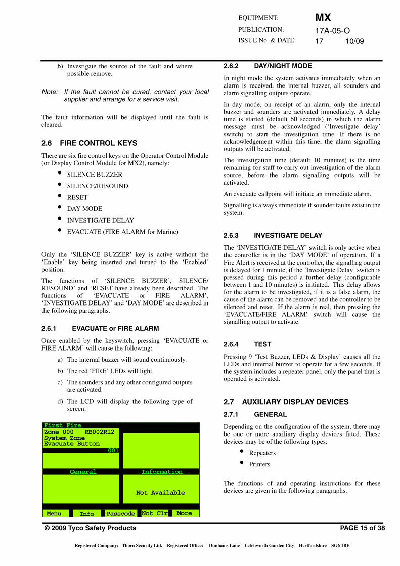
b) Investigate the source of the fault and wherepossible remove.
Note: If the fault cannot be cured, contact your localsupplier and arrange for a service visit.
The fault information will be displayed until the fault iscleared.
2.6 FIRE CONTROL KEYS
There are six fire control keys on the Operator Control Module(or Display Control Module for MX2), namely:
• SILENCE BUZZER
• SILENCE/RESOUND
• RESET
• DAY MODE
• INVESTIGATE DELAY
• EVACUATE (FIRE ALARM for Marine)
Only the ‘SILENCE BUZZER’ key is active without the‘Enable’ key being inserted and turned to the ‘Enabled’position.
The functions of ‘SILENCE BUZZER’, SILENCE/RESOUND’ and ‘RESET have already been described. Thefunctions of ‘EVACUATE or FIRE ALARM’,‘INVESTIGATE DELAY’ and ‘DAY MODE’ are described inthe following paragraphs.
2.6.1 EVACUATE or FIRE ALARM
Once enabled by the keyswitch, pressing ‘EVACUATE orFIRE ALARM’ will cause the following:
a) The internal buzzer will sound continuously.
b) The red ‘FIRE’ LEDs will light.
c) The sounders and any other configured outputsare activated.
d) The LCD will display the following type ofscreen:
First FireZone 000 RB002R12System ZoneEvacuate Button
General
Menu
F I R EFirst Fire
Information
Not Available
Info Passcode More
001
Not Clr
© 2009 Tyco Safety Products
Registered Company: Thorn Security Ltd. Registered Office: Dun
2.6.2 DAY/NIGHT MODE
In night mode the system activates immediately when analarm is received, the internal buzzer, all sounders andalarm signalling outputs operate.
In day mode, on receipt of an alarm, only the internalbuzzer and sounders are activated immediately. A delaytime is started (default 60 seconds) in which the alarmmessage must be acknowledged (‘Investigate delay’switch) to start the investigation time. If there is noacknowledgement within this time, the alarm signallingoutputs will be activated.
The investigation time (default 10 minutes) is the timeremaining for staff to carry out investigation of the alarmsource, before the alarm signalling outputs will beactivated.
An evacuate callpoint will initiate an immediate alarm.
Signalling is always immediate if sounder faults exist in thesystem.
2.6.3 INVESTIGATE DELAY
The ‘INVESTIGATE DELAY’ switch is only active whenthe controller is in the ‘DAY MODE’ of operation. If aFire Alert is received at the controller, the signalling outputis delayed for 1 minute, if the ‘Investigate Delay’ switch ispressed during this period a further delay (configurablebetween 1 and 10 minutes) is initiated. This delay allowsfor the alarm to be investigated, if it is a false alarm, thecause of the alarm can be removed and the controller to besilenced and reset. If the alarm is real, then pressing the‘EVACUATE/FIRE ALARM’ switch will cause thesignalling output to activate.
2.6.4 TEST
Pressing 9 ‘Test Buzzer, LEDs & Display’ causes all theLEDs and internal buzzer to operate for a few seconds. Ifthe system includes a repeater panel, only the panel that isoperated is activated.
2.7 AUXILIARY DISPLAY DEVICES
2.7.1 GENERAL
Depending on the configuration of the system, there maybe one or more auxiliary display devices fitted. Thesedevices may be of the following types:
• Repeaters
• Printers
The functions of and operating instructions for thesedevices are given in the following paragraphs.
PAGE 15 of 38
hams Lane Letchworth Garden City Hertfordshire SG6 1BE
MX17A-05-O17 10/09
2.7.2 REPEATERS
A repeater allows the controller to be operated from aremote location and provides remote indications of thestate of the controller. The front panel of the repeater isidentical to that of the controller (see Fig. 1) and allcontroller operations may be performed at the repeaterpanel.
2.7.3 PRINTERS
Refer to the manual supplied with the printer for operatinginstructions.
2.7.3.1 LCD REPEATERS
LCD Repeaters can:
• Display the alarm and fault messages asdisplayed on the Controller on a backlit 4 x20-character alphanumeric display.
• Provide an internal log for up to 150 events.
• Provide an internal audible warning of anevent.
• Allow the event log to be displayed usingthe scroll keys.
• Silence the internal buzzer and externalsounder (if fitted) with the key.
3. CONTROLLER FUNCTIONSAs stated, the MX controller has built-in functions. Thesefunctions allow the operator to perform such actions asviewing the event log, setting the date and time, etc. Thefunctions are arranged according to sophistication andaccess to certain of them necessarily needs to be restrictedto trained staff.
The control of access has been achieved by assigningfunctions to Access Levels, each Access Level having anassociated numeric passcode. The passcode for aparticular Access Level is defined at system configuration.
MUTE
PAGE 16 of 38
3.1 ACCESS LEVELS
3.1.1 GENERAL
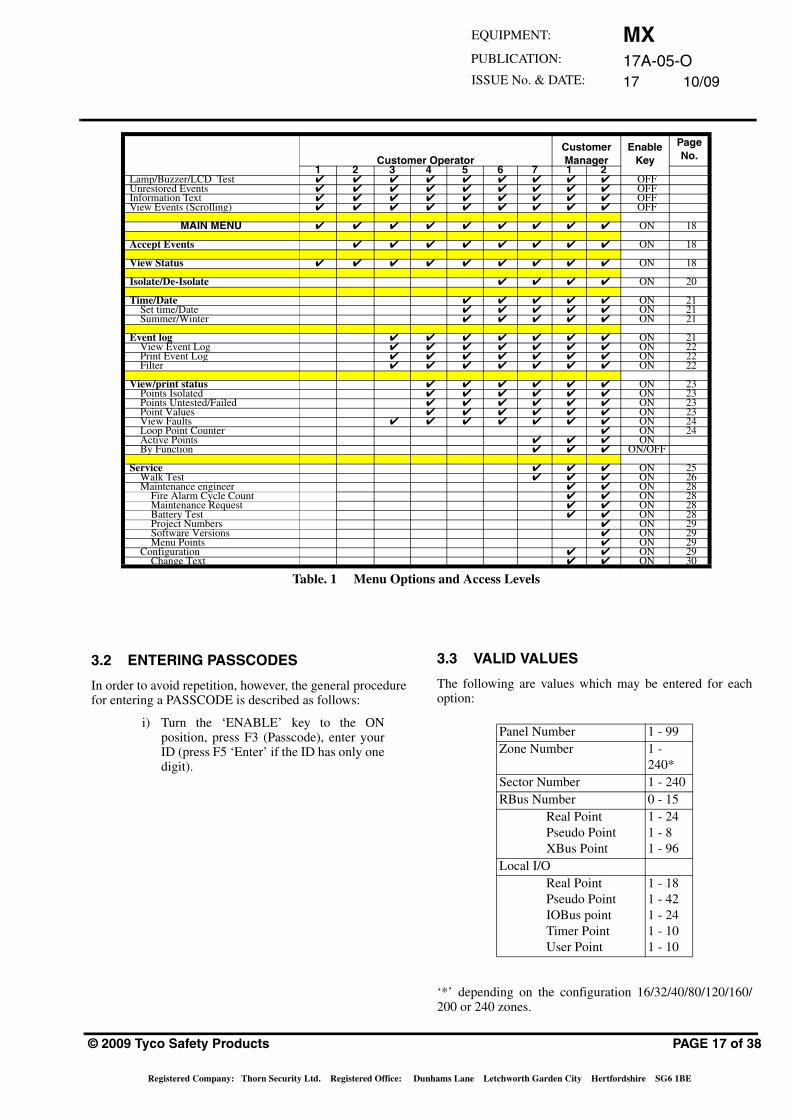
The access levels available are as follows:
• Customer Operator 1 to 7 - 4 digits
• Customer Manager 1 - 5 digits
• Customer Manager 2 - 5 digits
These access levels are described in the followingparagraphs. A maximum of 99 Passcodes are availablewhich may be split between Access Levels as required.
Note: The Customer Operator 1 Access Level isachieved by turning the ‘ENABLE’ key to theenable position (ie, a Passcode is notrequired).
Table 1 contains Access Levels and Menu Optionsavailable at each level.
MX17A-05-O17 10/09
EQUIPMENT:
PUBLICATION:
ISSUE No. & DATE:
EnableKey
PageNo.Customer Operator
CustomerManager
1 2 3 4 5 6 7 1 2Lamp/Buzzer/LCD Test ✔ ✔ ✔ ✔ ✔ ✔ ✔ ✔ ✔ OFFUnrestored Events ✔ ✔ ✔ ✔ ✔ ✔ ✔ ✔ ✔ OFFInformation Text ✔ ✔ ✔ ✔ ✔ ✔ ✔ ✔ ✔ OFFView Events (Scrolling) ✔ ✔ ✔ ✔ ✔ ✔ ✔ ✔ ✔ OFF
MAIN MENU ✔ ✔ ✔ ✔ ✔ ✔ ✔ ✔ ✔ ON 18
Accept Events ✔ ✔ ✔ ✔ ✔ ✔ ✔ ✔ ON 18
View Status ✔ ✔ ✔ ✔ ✔ ✔ ✔ ✔ ✔ ON 18
Isolate/De-Isolate ✔ ✔ ✔ ✔ ON 20
Time/Date ✔ ✔ ✔ ✔ ✔ ON 21Set time/Date ✔ ✔ ✔ ✔ ✔ ON 21Summer/Winter ✔ ✔ ✔ ✔ ✔ ON 21
Event log ✔ ✔ ✔ ✔ ✔ ✔ ✔ ON 21View Event Log ✔ ✔ ✔ ✔ ✔ ✔ ✔ ON 22Print Event Log ✔ ✔ ✔ ✔ ✔ ✔ ✔ ON 22Filter ✔ ✔ ✔ ✔ ✔ ✔ ✔ ON 22
View/print status ✔ ✔ ✔ ✔ ✔ ✔ ON 23Points Isolated ✔ ✔ ✔ ✔ ✔ ✔ ON 23Points Untested/Failed ✔ ✔ ✔ ✔ ✔ ✔ ON 23Point Values ✔ ✔ ✔ ✔ ✔ ✔ ON 23View Faults ✔ ✔ ✔ ✔ ✔ ✔ ✔ ON 24Loop Point Counter ✔ ON 24Active Points ✔ ✔ ✔ ONBy Function ✔ ✔ ✔ ON/OFF
Service ✔ ✔ ✔ ON 25Walk Test ✔ ✔ ✔ ON 26Maintenance engineer ✔ ✔ ON 28
Fire Alarm Cycle Count ✔ ✔ ON 28Maintenance Request ✔ ✔ ON 28Battery Test ✔ ✔ ON 28Project Numbers ✔ ON 29Software Versions ✔ ON 29Menu Points ✔ ON 29
Configuration ✔ ✔ ON 29Change Text ✔ ✔ ON 30
Table. 1 Menu Options and Access Levels
3.2 ENTERING PASSCODES
In order to avoid repetition, however, the general procedurefor entering a PASSCODE is described as follows:
i) Turn the ‘ENABLE’ key to the ONposition, press F3 (Passcode), enter yourID (press F5 ‘Enter’ if the ID has only onedigit).
© 2009 Tyco Safety Products
Registered Company: Thorn Security Ltd. Registered Office: Du
3.3 VALID VALUES
The following are values which may be entered for eachoption:
‘*’ depending on the configuration 16/32/40/80/120/160/200 or 240 zones.
Panel Number 1 - 99Zone Number 1 -
240*Sector Number 1 - 240RBus Number 0 - 15
Real PointPseudo PointXBus Point
1 - 241 - 81 - 96
Local I/OReal PointPseudo PointIOBus pointTimer PointUser Point
1 - 181 - 421 - 241 - 101 - 10
PAGE 17 of 38
nhams Lane Letchworth Garden City Hertfordshire SG6 1BE
MX17A-05-O17 10/09
3.4 MAIN MENU
When the system is in quiescent mode (ie, displaying thedate and time), entering a passcode affords the user accessto the main menu. The structure of this menu is shownbelow.
The menu shown is for Customer Manager 2 level. Only theoptions appropriate to the access level entered will bedisplayed.
Each of the options available leads to further menus orfunctions, which are described in the following paragraphs.
3.5 ACCEPT EVENTS
Allows displayed events to be accepted. Press 1 from themain menu, the following type of screen will be displayed:
Use the F4 Key ‘<<’ and F5 key ‘>>’ keys to move betweenevents. Use F3 ‘Accept’ to accept an event.
3.6 VIEW STATUS
Allows the status of all points and zones on the system to beviewed. Press 2 from the Main menu, the following type ofscreen will be displayed:
1 - Accept Events2 - View Status3 - Isolate/De-Isol4 - Time / Date5 - Event Log6 - View/Print Data7 - Service8 - Configuration9 - Test Buzzer, LEDs & Display
Alarm Count: 0021
MX Panel
Thu, 26-Jul-07 00:01
Company Name
General
Back
Main menu
Zone 000 R10System ZoneBattery Fault IP
BATTERY FAULT
01-Mar-00 14:15:02Digital Input
SYSTEM
Thu, 26-Jul-07 14:15
Company Name
Fault 02
General
Back
Accept Events
1000Accept >><<
PAGE 18 of 38
Point - allows the status of any points on the system (bothinputs and outputs) to be checked.
Point I/P only - allows the status of only input devices to bechecked (eg, detectors).
Point O/P only- allows the status of only output devices to bechecked (eg, sounders, functional bases, etc.).
Zone - allows the total status of all points in a specified zoneto be checked.
Zone Maps - a zone map can be displayed for Alarm, Fault,Test, Isolated Inputs Protection Equipment, Sounders andPlant Equipment states. A grid of 80 zones is displayedwhich can be scrolled between pages.
Network Status - allows the status of panels on the networkto be checked (only if a network is configured).
Select the required number from the View Status menu, thefollowing type of screen will be displayed:
Select the type of Point or Zone:
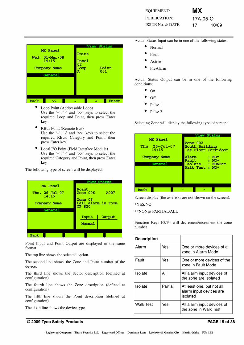
1) Loop Point (Addressable Loop).
2) RBus Point.
3) Local I/O Point.
The following type of screen will be displayed:
Note: If the panel is in a networked system, the panelnumber will be shown as in the followingexample.
1 - Point2 - Point I/P only3 - Point O/P only4 - Zone5 - Zone Maps6 - Network Status
MX Panel
Wed, 01-Mar-09 14:15
Company Name
General
Back
View Status
Point
1 - Loop Point2 - RBus Point3 - Local I/O Point
MX Panel
Thu, 26-Jul-07 14:15
Company Name
General
Back
View Status
MX17A-05-O17 10/09
EQUIPMENT:
PUBLICATION:
ISSUE No. & DATE:
• Loop Point (Addressable Loop)Use the ‘+’, ‘-’ and ‘>>’ keys to select therequired Loop and Point, then press Enterkey.
• RBus Point (Remote Bus)Use the ‘+’, ‘-’ and ‘>>’ keys to select therequired RBus, Category and Point, thenpress Enter key.
• Local I/O Point (Field Interface Module)Use the ‘+’, ‘-’ and ‘>>’ keys to select therequired Category and Point, then press Enterkey.
The following type of screen will be displayed:
Point Input and Point Output are displayed in the sameformat.
The top line shows the selected option.
The second line shows the Zone and Point number of thedevice.
The third line shows the Sector description (defined atconfiguration).
The fourth line shows the Zone description (defined atconfiguration).
The fifth line shows the Point description (defined atconfiguration).
The sixth line shows the device type.
Point
Panel02Loop Point A 001
MX Panel
Wed, 01-Mar-08 14:15
Company Name
General
Back
View Status
>> - + Enter
PointZone 006 A007
Zone 06Call alarm in roomCP 820
Input Output
Normal
MX Panel
Thu, 26-Jul-07 14:15
Company Name
General
Back
View Status
© 2009 Tyco Safety Products
Registered Company: Thorn Security Ltd. Registered Office: Du
Actual Status Input can be in one of the following states:
• Normal
• Fault
• Active
• PreAlarm
Actual Status Output can be in one of the followingconditions:
• On
• Off
• Pulse 1
• Pulse 2
Selecting Zone will display the following type of screen:
Screen display (the asterisks are not shown on the screen):
*YES/NO
**NONE/ PARTIAL/ALL
Function Keys F3/F4 will decrement/increment the zonenumber.
Description
Alarm Yes One or more devices of a zone in Alarm Mode
Fault Yes One or more devices of the zone in Fault Mode
Isolate All All alarm input devices of the zone are Isolated
Isolate Partial At least one, but not all alarm input devices are Isolated
Walk Test Yes All alarm input devices of the zone in Walk Test
Zone 002South Building1st Floor Corridoor
Alarm : NO*Fault : NO*Isolate : NONE**Walk Test : NO*
MX Panel
Thu, 26-Jul-07 14:15
Company Name
General
Back
View Status
_ +
PAGE 19 of 38
nhams Lane Letchworth Garden City Hertfordshire SG6 1BE
MX17A-05-O17 10/09
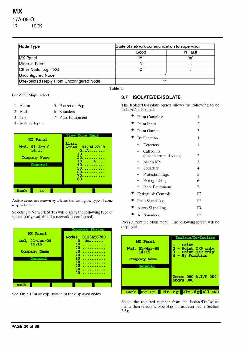
For Zone Maps, select:
Node Type State of network communication to supervisorGood In Fault
MX Panel ‘M’ ‘m’Minerva Panel ‘N’ ‘n’Other Node, e.g. TXG ‘O’ ‘o’Unconfigured Node ‘.’Unexpected Reply From Unconfigured Node ‘?’
Table 1:
1 - Alarm 5 - Protection Eqp.
2 - Fault 6 - Sounders
3 - Test 7 - Plant Equipment
4 - Isolated Inputs
3.7 ISOLATE/DE-ISOLATE
The Isolate/De-isolate option allows the following to beisolated/de-isolated:
• Point Complete 1
• Point Input 2
• Point Output 3
Active zones are shown by a letter indicating the type of zonemap selected.
Selecting 6 Network Status will display the following type ofscreen (only available if a network is configured):
See Table 1 for an explanation of the displayed codes.
AlarmZones 0123456789 0..A....... 10.......... 20.......... 30.....A.... 40.......... 50.......... 60.......... 70.......... 80.
MX Panel
Wed, 01-Jan-0 14:15
Company Name
General
Back
View Zone Maps
>>
MX Panel
Wed, 01-Jan-09 14:15
Company Name
General
Back
Network Status
Nodes 0123456789 0 Mm...... 10 .......... 20 .......... 30 .......... 40 .......... 50 .......... 60 .......... 70 .......... 80 .......... 90 ..........
PAGE 20 of 38
• By Function 4
• Detectors 1
• Callpoints(also interrupt devices) 2
• Alarm I/Ps 3
• Sounders 4
• Protection Eqp. 5
• Extinguishing 6
• Plant Equipment 7
• Extinguish Controls F2
• Fault Signalling F3
• Alarm Signalling F4
• All Sounders F5
Press 3 from the Main menu. The following screen will bedisplayed:
Select the required number from the Isolate/De-Isolatemenu, then select the type of point (as described in Section3.5):
1 - Point2 - Point I/P only3 - Point O/P only4 - By Function
Zones 000 A.I/P 000Sndrs 000
MX Panel
Wed, 01-Mar-09 14:15
Company Name
General
Back
Isolate/De-Isolate
Alm Sig All SNDFlt SigExt.Ctl
MX17A-05-O17 10/09
EQUIPMENT:
PUBLICATION:
ISSUE No. & DATE:
• Loop Point (Addressable Loop)Use the ‘+’, ‘-’ and ‘>>’ keys to select therequired Loop and Point, then press Enterkey.
• RBus Point (Remote Bus)Use the ‘+’, ‘-’ and ‘>>’ keys to select therequired RBus, Category and Point, thenpress Enter key.
• Local I/O Point (Field Interface Module)Use the ‘+’, ‘-’ and ‘>>’ keys to select therequired Category and Point, then pressEnter key.
CAUTION:
Isolating I/O points may break compliance with EN54. Caution should be exercised when
dealing with mandatory switches and indicators. Such operations are reserved for
authorised trained personnel only.
The following screen shows an example of Point isolation:
In the ‘Customer Operator’ access levels, only points on theaddressable loop can be isolated or de-isolated.
Isolations are counted and displayed (eg, Isol 001). If onlythe input or output of a point is isolated, this is counted as acomplete isolation of the point.
Point CompleteZone 002 B002South Building1st Floor CorridoorRoom 117801 H
Status IP: NormalISOLATED INPUT
2 - De-Isolate
MX Panel
Wed, 01-Mar-08 14:15
Company Name
Isola 001
General
Back
Isolate/De-Isolate
Isolation Status
© 2009 Tyco Safety Products
Registered Company: Thorn Security Ltd. Registered Office: Du
The following screen shows an example of Zone isolation:
Successes: Number of points that wereIsolated
Matches: Number of points in Zone (detectors)
The following screen shows an example of All Soundersisolation:
Successes: Number of sounders (De-)Isolated
Matches: Number of sounders in Zone
Isola: Number of points
Iso.S: Number of isolated sounders
Zone DetectorsZone 001
Zone 01
IsolateAll
Successes : 003Matches : 003
MX Panel
Thu, 26-Jul-07 14:15
Company Name
Isola 003
General
Back
Isolate/De-Isolate
All Sounders
Successes : 006Matches : 006
MX Panel
Wed, 01-Mar-00 14:15
Company Name
Isola 006Iso.S 006
General
Back
Isolate/De-Isolate
PAGE 21 of 38
nhams Lane Letchworth Garden City Hertfordshire SG6 1BE
MX17A-05-O17 10/09
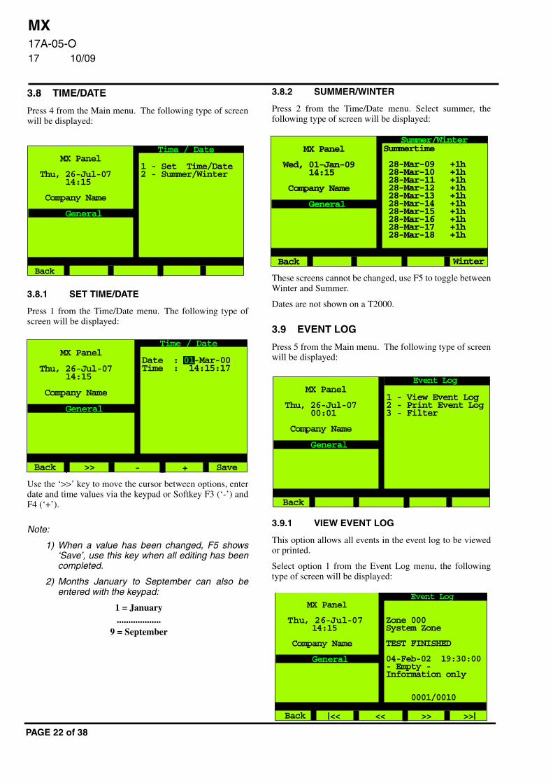
3.8 TIME/DATE
Press 4 from the Main menu. The following type of screenwill be displayed:
3.8.1 SET TIME/DATE
Press 1 from the Time/Date menu. The following type ofscreen will be displayed:
Use the ‘>>’ key to move the cursor between options, enterdate and time values via the keypad or Softkey F3 (‘-’) andF4 (‘+’).
Note:
1) When a value has been changed, F5 shows‘Save’, use this key when all editing has beencompleted.
2) Months January to September can also beentered with the keypad:
1 = January ...................
9 = September
1 - Set Time/Date2 - Summer/Winter
MX Panel
Thu, 26-Jul-07 14:15
Company Name
General
Back
Time / Date
MX Panel
Thu, 26-Jul-07 14:15
Company Name
General
Back
Time / Date
>> - +
Date : 01-Mar-00Time : 14:15:17
Save
PAGE 22 of 38
3.8.2 SUMMER/WINTER
Press 2 from the Time/Date menu. Select summer, thefollowing type of screen will be displayed:
These screens cannot be changed, use F5 to toggle betweenWinter and Summer.
Dates are not shown on a T2000.
3.9 EVENT LOG
Press 5 from the Main menu. The following type of screenwill be displayed:
3.9.1 VIEW EVENT LOG
This option allows all events in the event log to be viewedor printed.
Select option 1 from the Event Log menu, the followingtype of screen will be displayed:
Summertime
28-Mar-09 +1h 28-Mar-10 +1h 28-Mar-11 +1h 28-Mar-12 +1h 28-Mar-13 +1h 28-Mar-14 +1h 28-Mar-15 +1h 28-Mar-16 +1h 28-Mar-17 +1h 28-Mar-18 +1h
MX Panel
Wed, 01-Jan-09 14:15
Company Name
General
Back
Summer/Winter
Winter
1 - View Event Log2 - Print Event Log3 - Filter
MX Panel
Thu, 26-Jul-07 00:01
Company Name
General
Back
Event Log
Zone 000System Zone
TEST FINISHED
04-Feb-02 19:30:00- Empty -Information only 0001/0010
MX Panel
Thu, 26-Jul-07 14:15
Company Name
General
Back
Event Log
<< >>>><<
MX17A-05-O17 10/09
EQUIPMENT:
PUBLICATION:
ISSUE No. & DATE:
The latest event is displayed, use the ‘<<’ and ‘>>’ keys toscroll through the log and the ‘|<<’ to move to the back ofthe log or the ‘>>|’ key to move to the front of the log.
• EventID - Displays the absolute number ofan event (1 to 65,535). After 65,535 it startswith 1 again.
• 0001/0010 - The first number is the actualposition in the event log (1 means it displaysthe newest event log entry. The secondnumber displays the number of entries in theevent log (max. 3,000).
The newest/last event will be displayed when the Event Logis entered.
3.9.2 PRINT EVENT LOG
Select option 2 from the Event Log menu, the followingtype of screen will be displayed:
This menu option is only available if at least one printer isconfigured.
The destination printer can be selected if more than oneprinter is configured.
The priorities available are shown in the following table:
It is always printed from the selected priority (eg, Non LifeRisk) to the Highest Priority (eg, Non Life Risk, Level 12,Life Risk Alarm and General Alarm).
Lowest Priority Information Only. Reset/Restarted. Expected Events. Isolates. Warnings. Visible Isolate. Other Faults. Critical Faults. Gas Alert. Alarm Threshold. Non-Life Risk . Level 12. Life Risk Alarms
Highest Priority General Alarm
MX Panel
Thu, 26-Jul-07 14:15
Company Name
General
Back
Event Log
Destination :Default Printer
How far back:to start: 0010
How many entriesrequired: 0010
Lowest priorityof interest : 00 Print initiated
© 2009 Tyco Safety Products
Registered Company: Thorn Security Ltd. Registered Office: Du
3.9.3 FILTER
Select option 3 from the Event Log menu, the followingtype of screen will be displayed:
It is possible to view and to print the events of singlecategories. The category is selected by pressing theappropriate option number. It is also possible to selectseveral categories, the selected categories are denoted by a‘+’ sign.
Press F4 to view the selected categorie(s) as described inSection 3.8.1 or F5 to print the selected category(s) asdescribed in Section 3.8.2.
3.10 VIEW/PRINT DATAAllows the following options to be viewed/printed. Onnetworked systems, the status of any panel on the networkmay be viewed/printed:
• Points Isolated
• Points Untested/Failed (during Walk Test)
• Point Values
• View Faults (no print option)
• Loop Point Counters (no print option)
• Active Points
• By Function
Select option 6 from the Main menu, the following type ofscreen will be displayed:
1 - Fire -2 - Gas Alert -3 - Pre Alarm -4 - Supervisory -5 - Fault -6 - Isolate -7 - Test Mode -8 - Warning -9 - Information -
MX Panel
Thu, 26-Jul-07 14:15
Company Name
General
Back
Event Log
PrintView
1 - Points Isolated2 - Pts Unt./Failed3 - Point Values4 - View Faults5 - Loop Point Ctrs
7 - Active Points8 - By Function
MX Panel
Wed, 01-Jan-08 14:15
Company Name
General
Back
View/Print Data
PAGE 23 of 38
nhams Lane Letchworth Garden City Hertfordshire SG6 1BE
MX17A-05-O17 10/09
3.10.1 VIEW/PRINT POINTS ISOLATEDSelect option 1 from the View/Print Status menu, thefollowing type of screen will be displayed:
Note: If the panel is part of a networked system,another screen is displayed before the abovescreen where the panel number may beselected.
Press F5 ‘Print’ to print a list of all isolated points.
The F2 Key selects either isolated inputs or isolated outputs.
Points which are completely isolated (input and output) willbe shown in both lists.
3.10.2 VIEW/PRINT POINTS UNTESTED/FAILED
Note: This option only works whilst still in Walktest.
Select option 2 from the View/Print Status menu, thefollowing type of screen will be displayed:
Note: If the panel is part of a networked system,another screen is displayed before the abovescreen where the panel number may beselected.
InputTotal : 004
Zone 001 -001 BPoint Text--------------------001 -002 BPoint Text
MX Panel
Thu, 26-Jul-07 14:15
Company Name
General
Back
Points Isolated
PrintOutput
Total : 004
Zone 001 -001 BPoint Text--------------------Zone 001 -002 BPoint Text
MX Panel
Thu, 26-Jul-07 14:15
Company Name
General
Back
Pts Untested/Failed
PAGE 24 of 38
Press F5 to print the Untested/Failed points.
Points which are not tested or points which return the wrongcondition are then listed.
3.10.3 VIEW/PRINT POINT VALUESSelect option 3 from the View/Print Status menu, thefollowing type of screen will be displayed:
Select the panel number (if the panel is part of a networkedsystem), loop and point number required.
‘>>’ - next field
‘_’ - the number is decremented
‘+’ - the number is incremented
Pressing F5 displays the following screen:
Press F5 to print the Point Values of the selected loop (notonly the displayed point).
Panel 02
Loop PointA 002
MX Panel
Thu, 26-Jul-07 14:15
Company Name
General
Back
Point Values
Enter >> - +
Zone 003 A023
Zone 03Heat Sensor Device801 H
Real: 801HMode: Std R.o.(21)Sens: N/A
22 C (073)
MX Panel
Wed, 01-Jan-09 14:15
Company Name
General
Back
Point Values
o
MX17A-05-O17 10/09
EQUIPMENT:
PUBLICATION:
ISSUE No. & DATE:
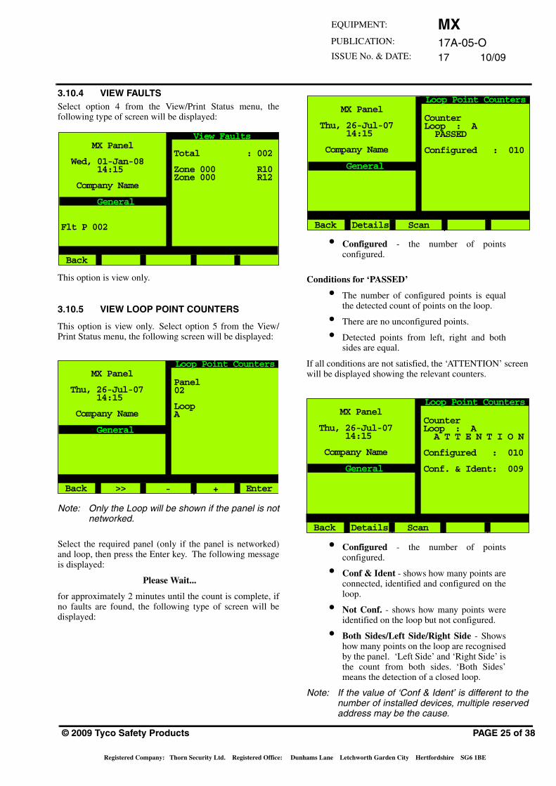
3.10.4 VIEW FAULTSSelect option 4 from the View/Print Status menu, thefollowing type of screen will be displayed:
This option is view only.
3.10.5 VIEW LOOP POINT COUNTERS
This option is view only. Select option 5 from the View/Print Status menu, the following screen will be displayed:
Note: Only the Loop will be shown if the panel is notnetworked.
Select the required panel (only if the panel is networked)and loop, then press the Enter key. The following messageis displayed:
Please Wait...
for approximately 2 minutes until the count is complete, ifno faults are found, the following type of screen will bedisplayed:
Total : 002
Zone 000 R10Zone 000 R12
MX Panel
Wed, 01-Jan-08 14:15
Company Name
Flt P 002
General
Back
View Faults
Panel02
LoopA
MX Panel
Thu, 26-Jul-07 14:15
Company Name
General
Back
Loop Point Counters
>> - + Enter
© 2009 Tyco Safety Products
Registered Company: Thorn Security Ltd. Registered Office: Du
• Configured - the number of pointsconfigured.
Conditions for ‘PASSED’
• The number of configured points is equalthe detected count of points on the loop.
• There are no unconfigured points.
• Detected points from left, right and bothsides are equal.
If all conditions are not satisfied, the ‘ATTENTION’ screenwill be displayed showing the relevant counters.
• Configured - the number of pointsconfigured.
• Conf & Ident - shows how many points areconnected, identified and configured on theloop.
• Not Conf. - shows how many points wereidentified on the loop but not configured.
• Both Sides/Left Side/Right Side - Showshow many points on the loop are recognisedby the panel. ‘Left Side’ and ‘Right Side’ isthe count from both sides. ‘Both Sides’means the detection of a closed loop.
Note: If the value of ‘Conf & Ident’ is different to thenumber of installed devices, multiple reservedaddress may be the cause.
CounterLoop : A PASSED
Configured : 010
MX Panel
Thu, 26-Jul-07 14:15
Company Name
General
Back
Loop Point Counters
Details Scan
CounterLoop : A A T T E N T I O N
Configured : 010
Conf. & Ident: 009
MX Panel
Thu, 26-Jul-07 14:15
Company Name
General
Back
Loop Point Counters
Details Scan
PAGE 25 of 38
nhams Lane Letchworth Garden City Hertfordshire SG6 1BE
MX17A-05-O17 10/09
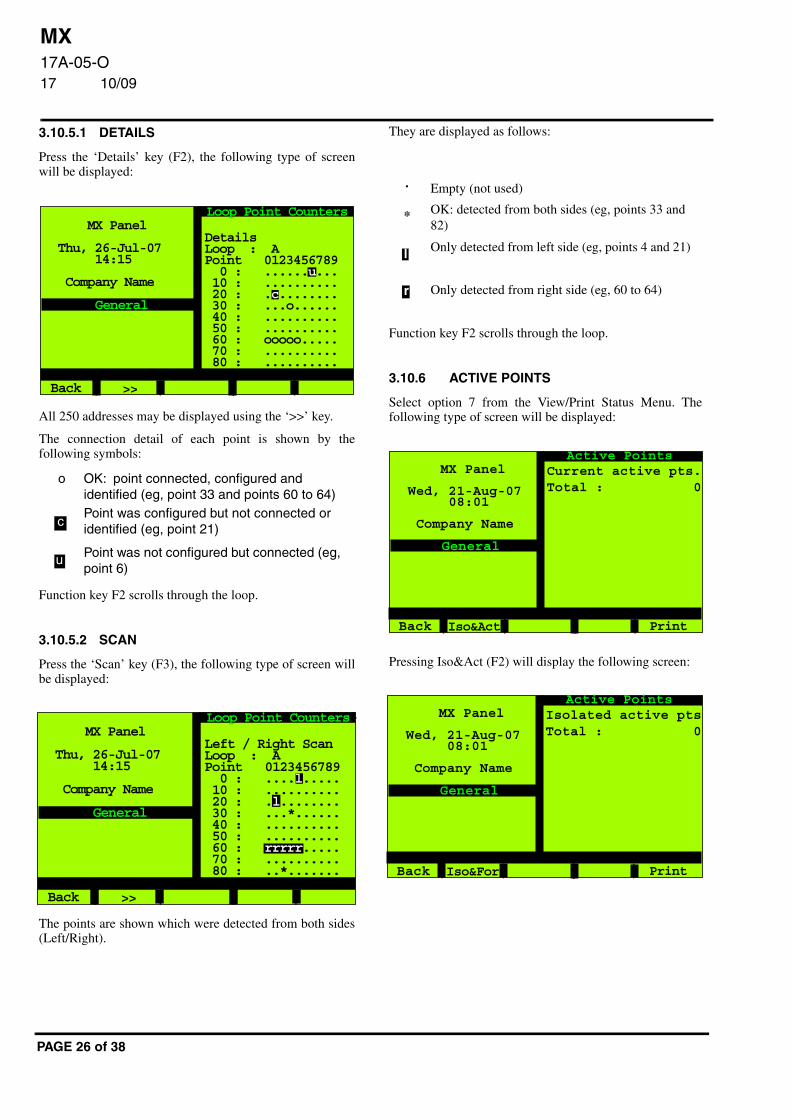
3.10.5.1 DETAILS
Press the ‘Details’ key (F2), the following type of screenwill be displayed:
All 250 addresses may be displayed using the ‘>>’ key.
The connection detail of each point is shown by thefollowing symbols:
Function key F2 scrolls through the loop.
3.10.5.2 SCAN
Press the ‘Scan’ key (F3), the following type of screen willbe displayed:
The points are shown which were detected from both sides(Left/Right).
o OK: point connected, configured and identified (eg, point 33 and points 60 to 64)Point was configured but not connected or identified (eg, point 21)
Point was not configured but connected (eg, point 6)
MX Panel
Thu, 26-Jul-07 14:15
Company Name
General
Back
Loop Point Counters
>>
DetailsLoop : APoint 0123456789 0 : ......u... 10 : .......... 20 : .c........ 30 : ...o...... 40 : .......... 50 : .......... 60 : ooooo..... 70 : .......... 80 : ..........
c
u
MX Panel
Thu, 26-Jul-07 14:15
Company Name
General
Back
Loop Point Counters
>>
Left / Right ScanLoop : APoint 0123456789 0 : ....l..... 10 : .......... 20 : .l........ 30 : ...*...... 40 : .......... 50 : .......... 60 : rrrrr..... 70 : .......... 80 : ..*.......
PAGE 26 of 38
They are displayed as follows:
Function key F2 scrolls through the loop.
3.10.6 ACTIVE POINTS
Select option 7 from the View/Print Status Menu. Thefollowing type of screen will be displayed:
Pressing Iso&Act (F2) will display the following screen:
Empty (not used)
OK: detected from both sides (eg, points 33 and 82)
Only detected from left side (eg, points 4 and 21)
Only detected from right side (eg, 60 to 64)
.
*
l
r
MX Panel
Wed, 21-Aug-07 08:01
Company Name
General
Back
Active Points
Current active pts.Total : 0
Iso&Act Print
MX Panel
Wed, 21-Aug-07 08:01
Company Name
General
Back
Active Points
Isolated active ptsTotal : 0
Iso&For Print
MX17A-05-O17 10/09
EQUIPMENT:
PUBLICATION:
ISSUE No. & DATE:
Pressing Iso&For (F2) will display the following screen:
3.10.7 BY FUNCTION
Select option 8 (also available via F1 (View) button) fromthe View/Print Status Menu. The following type of screenwill be displayed:
Screens for options 2, 3, 4, 5 and 6 are the same type as foroption 1 Fire Inputs.
3.10.7.1 FIRE INPUTS
Select option 1 from the By Function menu, the followingscreen will be displayed:
MX Panel
Wed, 21-Aug-07 08:01
Company Name
General
Back
Active Points
Isolated Forced ptsTotal : 0
All Act Print
MX Panel
Wed, 21-Aug-07 08:01
Company Name
General
Back
By Function
1 - Fire Inputs2 - Non-Fire Inputs3 - All Loop O/Ps4 - Sounders5 - Protection Eqp.6 - Plant Equipment
MX Panel
Wed, 21-Aug-07 08:01
Company Name
General
Back
Fire Inputs
1 - Active2 - Fault3 - Isolated
© 2009 Tyco Safety Products
Registered Company: Thorn Security Ltd. Registered Office: D
Select option 1 from the Fire Inputs menu, the followingscreen will be displayed:
Select option 2 from the Fire Inputs menu, the followingscreen will be displayed:
Select option 3 from the Fire Inputs menu, the followingscreen will be displayed:
MX Panel
Wed, 21-Aug-07 08:01
Company Name
General
Back
Active Fire IPs
Panel: 1Page : 0/ 0
MX Panel
Wed, 21-Aug-07 08:01
Company Name
General
Back
Fire IPs in Fault
Panel: 1Page : 0/ 0
MX Panel
Wed, 21-Aug-07 08:01
Company Name
General
Back
Isolated Fire IPs
Panel: 1Page : 0/ 0
PAGE 27 of 38
unhams Lane Letchworth Garden City Hertfordshire SG6 1BE
MX17A-05-O17 10/09
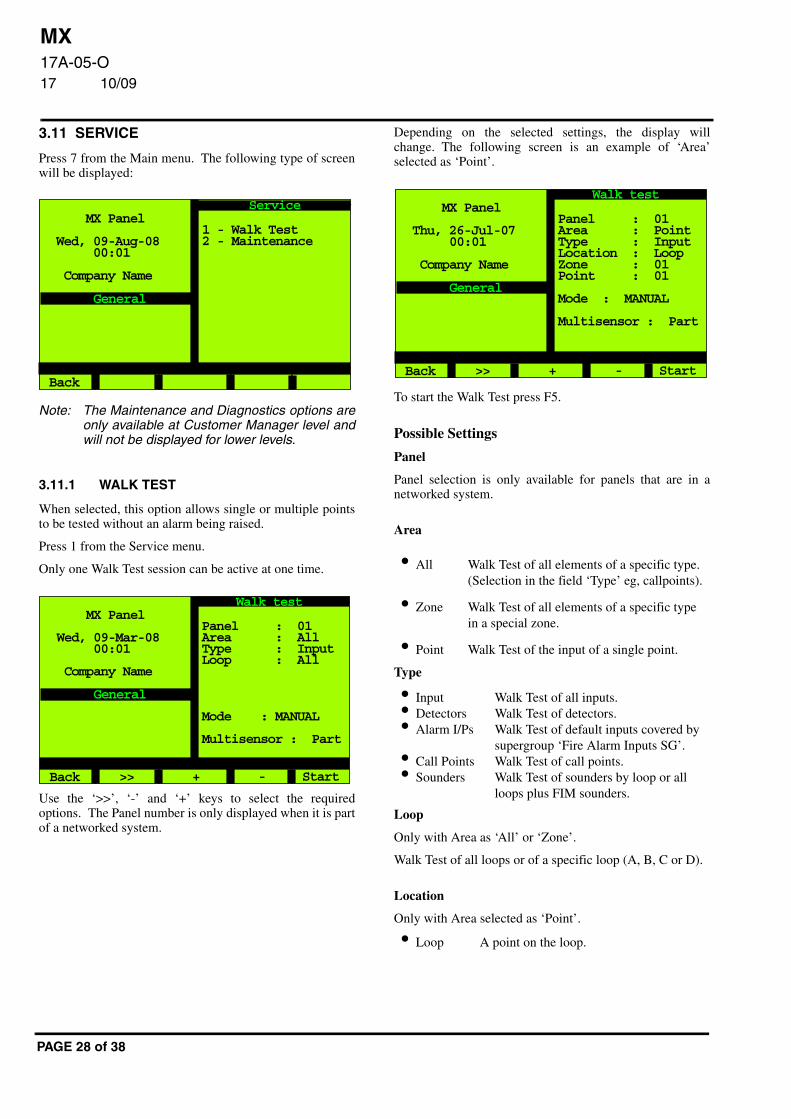
3.11 SERVICE
Press 7 from the Main menu. The following type of screenwill be displayed:
Note: The Maintenance and Diagnostics options areonly available at Customer Manager level andwill not be displayed for lower levels.
3.11.1 WALK TEST
When selected, this option allows single or multiple pointsto be tested without an alarm being raised.
Press 1 from the Service menu.
Only one Walk Test session can be active at one time.
Use the ‘>>’, ‘-’ and ‘+’ keys to select the requiredoptions. The Panel number is only displayed when it is partof a networked system.
1 - Walk Test2 - Maintenance
MX Panel
Wed, 09-Aug-08 00:01
Company Name
General
Back
Service
Panel : 01Area : AllType : InputLoop : All
Mode : MANUAL
Multisensor : Part
MX Panel
Wed, 09-Mar-08 00:01
Company Name
General
Back
Walk test
>> + - Start
PAGE 28 of 38
Depending on the selected settings, the display willchange. The following screen is an example of ‘Area’selected as ‘Point’.
To start the Walk Test press F5.
Possible Settings
Panel
Panel selection is only available for panels that are in anetworked system.
Area
Type
Loop
Only with Area as ‘All’ or ‘Zone’.
Walk Test of all loops or of a specific loop (A, B, C or D).
Location
Only with Area selected as ‘Point’.
• All Walk Test of all elements of a specific type.(Selection in the field ‘Type’ eg, callpoints).
• Zone Walk Test of all elements of a specific type in a special zone.
• Point Walk Test of the input of a single point.
• Input Walk Test of all inputs.• Detectors Walk Test of detectors.• Alarm I/Ps Walk Test of default inputs covered by
supergroup ‘Fire Alarm Inputs SG’.• Call Points Walk Test of call points.• Sounders Walk Test of sounders by loop or all
loops plus FIM sounders.
• Loop A point on the loop.
Panel : 01Area : PointType : InputLocation : LoopZone : 01Point : 01
Mode : MANUAL
Multisensor : Part
MX Panel
Thu, 26-Jul-07 00:01
Company Name
General
Back
Walk test
>> + - Start
MX17A-05-O17 10/09
EQUIPMENT:
PUBLICATION:
ISSUE No. & DATE:
Zone
Only with Area selected as ‘Point’.
Point
Only with Area selected as ‘Point’.
Selection of a specific zone is possible.
Mode
MANUAL
Detectors to be tested manually.
AUTOMATIC
Only if type selected is ‘detector’
813P
This mode is only available if an 813P detector isconfigured. If an 813P detector fails this test, it must bemanually tested to confirm the failure.
Multisensor
It is only possible to select either ‘Automatic’, ‘Lasertest’ or‘Multisensor. The panel itself prevents selection of morethan one option.
Note: If ‘Full’ Walk Test is selected, both modes of thedetector must be activated (eg, both heat andoptical mode for 801PH).
If ‘Part’ Walk Test is selected, the detector hasto be activated in the mode in which it isoperating (eg, for 801PH optical and heat, bothmodes active, then activation of either theoptical or heat will activate the processing. Ifonly the heat mode is active, then onlyactivation of the heat mode will create analarm.
• Loop Selection of a specific zone is possible.
Self test will be carried out by detectors.The following detectors support the self test function:
801PH811PH801CH811CH801I
801PHEx811PHExn801CHEx811CHExn
• Full
• Part
© 2009 Tyco Safety Products
Registered Company: Thorn Security Ltd. Registered Office: Du
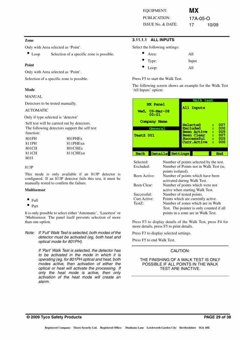
3.11.1.1 ALL INPUTS
Select the following settings:
• Area: All
• Type: Input
• Loop: All
Press F5 to start the Walk Test.
The following screen shows an example for the Walk Test‘All Inputs’ option:
Press F3 to display details of the Walk Test, press F4 formore details, press F5 to print details.
Press F3 to display selected settings.
Press F5 to end Walk Test.
CAUTION:
THE FINISHING OF A WALK TEST IS ONLY POSSIBLE IF ALL POINTS IN THE WALK
TEST ARE INACTIVE.
Selected: Number of points selected by the test.Excluded: Number of Points not in Walk Test (ie,
points isolated).Been Active: Number of points which have been
activated during Walk Test.Been Clear: Number of points which were not
active when starting Walk Test.Successful: Number of tested points.Curr.Active: Points which are currently active.TestZ: Number of zones which are in Walk
Test. The pointer is only counted if all points in a zone are in Walk Test.
All Inputs
Selected : 007Excluded : 000Been Active : 005Been Clear : 007Successful : 005Curr.Active : 000
MX Panel
Wed, 09-Mar-08 00:01
Company Name
General
Back
Walk test
Settings End
TestZ 001
Details
PAGE 29 of 38
nhams Lane Letchworth Garden City Hertfordshire SG6 1BE
MX17A-05-O17 10/09
3.11.1.2 SOUNDERS
Select ‘Sounders’ in the Type field.
No results will be shown on the display. The selectedsounders will be activated in a pulsing mode.
3.11.1.3 POINT
Select the following settings:
Press F5 to start the Walk Test.
The following screen shows an example for the Walk Test of‘Point Input’:
Press F3 for a display of selected settings.
Press F5 to end Walk Test.
• Area: Point.
• Type: Input (appears automatically).
• Location: Loop (appears automatically).
• Zone: Required number.
• Point: Required number.
• Selected: 1, if point is in Walk test.• Excluded: 1, if point is not in Walk Test (ie, if point
is isolated).• Activations: 1, if point was activated during Walk
Test.• Curr.Active: Yes, if point is currently active.• TestZ 001 Number of zones which are in Walk
Test. (The pointer is only counted if all points of a zone are in Walk Test. If one detector on the zone is switched off, the pointer is not decreased. In the case of Walk Test for one point, the pointer is only decreased if that point is the only point on the zone).
Point I/P onlyZone 006 A007
Zone 06Call alarm in roomCP820
Selected : 1Excluded : 0Activations : 0Curr.Active : NO
MX Panel
Wed, 09-Mar-08 00:01
Company Name
General
Back
Walk test
Settings End
TestZ 001
Details
PAGE 30 of 38
CAUTION:
THE FINISHING OF A WALK TEST IS ONLY POSSIBLE IF ALL POINTS IN THE WALK
TEST ARE INACTIVE.
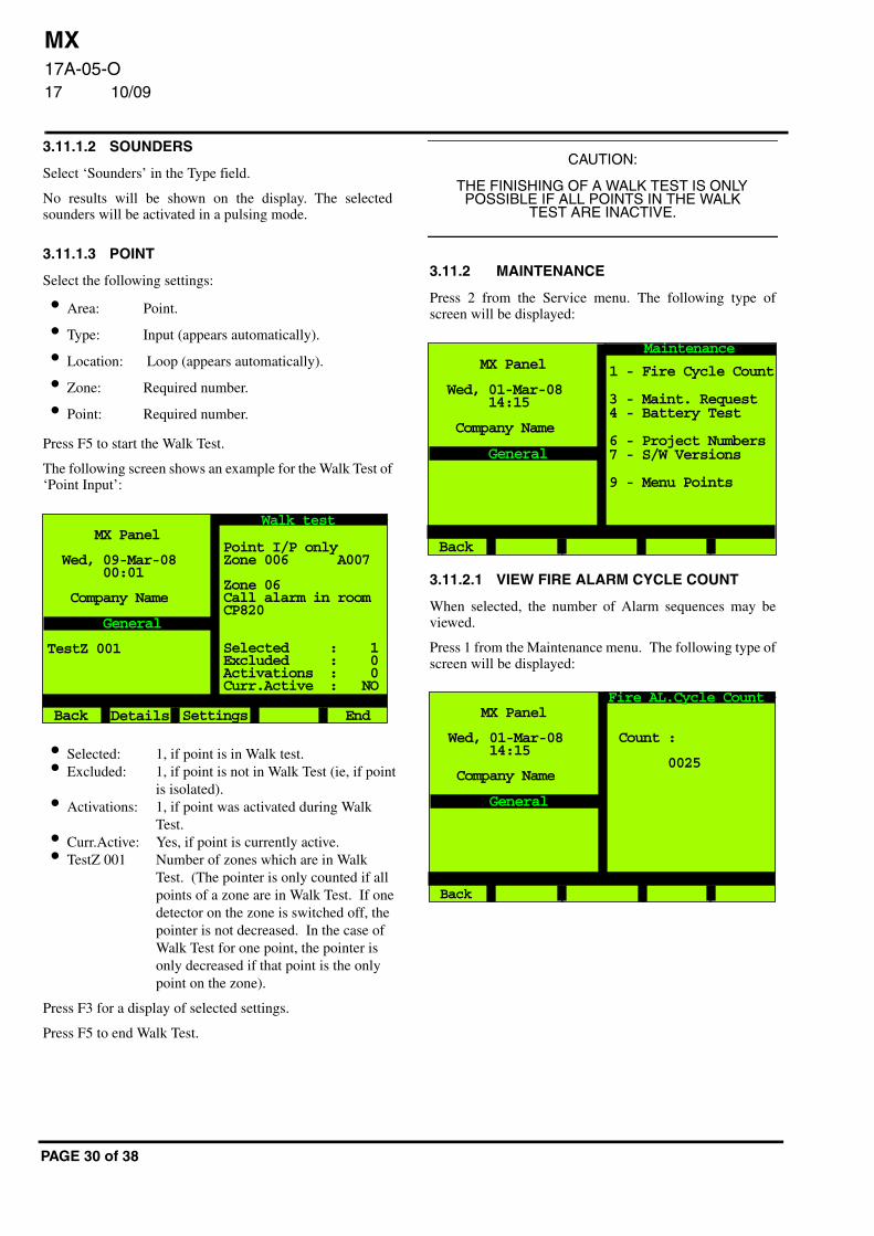
3.11.2 MAINTENANCE
Press 2 from the Service menu. The following type ofscreen will be displayed:
3.11.2.1 VIEW FIRE ALARM CYCLE COUNT
When selected, the number of Alarm sequences may beviewed.
Press 1 from the Maintenance menu. The following type ofscreen will be displayed:
1 - Fire Cycle Count
3 - Maint. Request4 - Battery Test
6 - Project Numbers7 - S/W Versions
9 - Menu Points
MX Panel
Wed, 01-Mar-08 14:15
Company Name
General
Back
Maintenance
Count :
0025
MX Panel
Wed, 01-Mar-08 14:15
Company Name
General
Back
Fire AL.Cycle Count
MX17A-05-O17 10/09
EQUIPMENT:
PUBLICATION:
ISSUE No. & DATE:
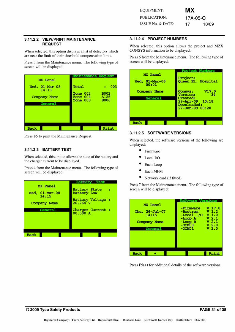
3.11.2.2 VIEW/PRINT MAINTENANCEREQUEST
When selected, this option displays a list of detectors whichare near the limit of their threshold compensation limit.
Press 3 from the Maintenance menu. The following type ofscreen will be displayed:
Press F5 to print the Maintenance Request.
3.11.2.3 BATTERY TEST
When selected, this option allows the state of the battery andthe charger current to be displayed.
Press 4 from the Maintenance menu. The following type ofscreen will be displayed:
Total : 003
Zone 002 B002Zone 004 A126Zone 008 B006
MX Panel
Wed, 01-Mar-08 14:15
Company Name
General
Back
Maintenance Request
Battery State :Battery Low
Battery Voltage :20.764 V
Charger Current :00.500 A
MX Panel
Wed, 01-Mar-08 14:15
Company Name
General
Back
Battery Test
© 2009 Tyco Safety Products
Registered Company: Thorn Security Ltd. Registered Office: Du
3.11.2.4 PROJECT NUMBERS
When selected, this option allows the project and MZXCONSYS information to be displayed.
Press 6 from the Maintenance menu. The following type ofscreen will be displayed:
3.11.2.5 SOFTWARE VERSIONS
When selected, the software versions of the following aredisplayed:
• Firmware
• Local I/O
• Each Loop
• Each MPM
• Network card (if fitted)
Press 7 from the Maintenance menu. The following type ofscreen will be displayed:
Press F5(+) for additional details of the software versions.
Project:Queen El. Hospital
Consys: V17.0Version: 34Created:29-Apr-09 10:18Downloaded:27-Jun-09 08:20
MX Panel
Wed, 01-Mar-06 00:01
Company Name
General
Back
Project Numbers
-Firmware V 17.0 -Bootrom V 1.2 -Local I/O V 1.0 -Loop A V 2.1 -Loop B V 2.1 -OCM00 V 2.0 -OCM01 V 2.0
MX Panel
Thu, 26-Jul-07 14:15
Company Name
General
Back
Software Versions
PAGE 31 of 38
nhams Lane Letchworth Garden City Hertfordshire SG6 1BE
MX17A-05-O17 10/09
3.11.2.6 MENU POINTS
When selected, this option allows any configured pointdisplayed to be operated by pressing the appropriate numberbutton, this will toggle from OFF to ON and ON to OFF.
Press 9 from the Maintenance menu. The following type ofscreen will be displayed:
3.11.3 CONFIGURATION
Press 8 from the Main menu. The following screen will bedisplayed:
‘Menu option 9- Restart’ will only be displayed if text hasbeen changed and the changes saved.
RESTRICTIONS ON THE USE OF THEFOLLOWING OPTION
When using Configuration menu option 1, ALWAYScommit configuration changes by using ‘Menu option 9 -Restart’ before leaving the panel.
Avoid ‘inactivity’ timeouts.
NEVER use the ‘Back’ option from the configuration menuif ‘Menu option 9 - Restart’ is showing.
If you do not want to commit changes, by using ‘Menuoption 9 - Restart’, option, turn the keyswitch to ‘OFF’position to avoid a timeout situation, do NOT USE the‘Back’ option.
MX Panel
Wed, 01-Mar-08 14:15
Company Name
General
Back
Menu Points
>>
Menu Point 1: OFFIsolate Zone
Menu Point 2: ONSensit.Change
Menu Point 3: -Unconfigured-
Menu Point 4: -Unconfigured-
ON
MX Panel
Wed, 01-Mar-08 14:15
Company Name
General
Back
Configuration
1 - Change Text
PAGE 32 of 38
Configuration changes across a network are possible, butchanges to more than one panel at a time MUST NOT beattempted within one session. When a panels configurationhas been changed, it must be restarted using menu option 9‘Restart’.
Failure to comply with these restrictions may lead tounpredictable effects or system instability.
3.11.3.1 CHANGE TEXT
Press 1 from the Configuration menu. The followingscreen will be displayed:
3.11.3.2 POINT TEXT MODIFY
Press 1 from the Change Text menu. The following screenwill be displayed:
Select the required loop and point then press Enter. Thefollowing type of screen will be displayed:
MX Panel
Wed, 01-Mar-08 14:15
Company Name
General
Back
Change Text
1 - Point Text2 - Zone Text3 - Sector Text4 - Panel Text5 - Info Text
MX Panel
Wed, 01-Mar-08 14:15
Company Name
General
Back
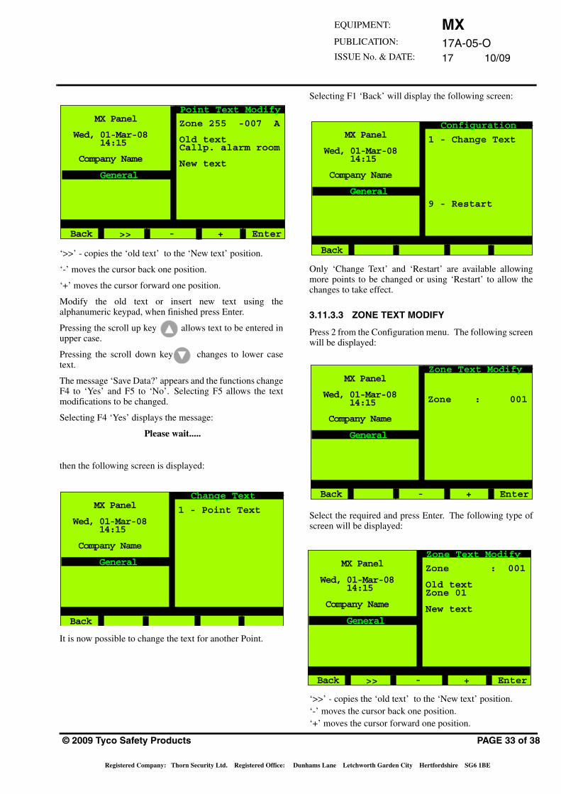
Point Text Modify
Loop : APoint : 001
>> - + Enter
MX17A-05-O17 10/09
EQUIPMENT:
PUBLICATION:
ISSUE No. & DATE:
‘>>’ - copies the ‘old text’ to the ‘New text’ position.
‘-’ moves the cursor back one position.
‘+’ moves the cursor forward one position.
Modify the old text or insert new text using thealphanumeric keypad, when finished press Enter.
Pressing the scroll up key allows text to be entered inupper case.
Pressing the scroll down key changes to lower casetext.
The message ‘Save Data?’ appears and the functions changeF4 to ‘Yes’ and F5 to ‘No’. Selecting F5 allows the textmodifications to be changed.
Selecting F4 ‘Yes’ displays the message:
Please wait.....
then the following screen is displayed:
It is now possible to change the text for another Point.
MX Panel
Wed, 01-Mar-08 14:15
Company Name
General
Back
Point Text Modify
Zone 255 -007 A
Old textCallp. alarm room
New text
>> - + Enter
MX Panel
Wed, 01-Mar-08 14:15
Company Name
General
Back
Change Text
1 - Point Text
© 2009 Tyco Safety Products
Registered Company: Thorn Security Ltd. Registered Office: Du
Selecting F1 ‘Back’ will display the following screen:
Only ‘Change Text’ and ‘Restart’ are available allowingmore points to be changed or using ‘Restart’ to allow thechanges to take effect.
3.11.3.3 ZONE TEXT MODIFY
Press 2 from the Configuration menu. The following screenwill be displayed:
Select the required and press Enter. The following type ofscreen will be displayed:
‘>>’ - copies the ‘old text’ to the ‘New text’ position.‘-’ moves the cursor back one position.‘+’ moves the cursor forward one position.
MX Panel
Wed, 01-Mar-08 14:15
Company Name
General
Back
Configuration
1 - Change Text
9 - Restart
MX Panel
Wed, 01-Mar-08 14:15
Company Name
General
Back
Zone Text Modify
Zone : 001
- + Enter
MX Panel
Wed, 01-Mar-08 14:15
Company Name
General
Back
Zone Text Modify
Zone : 001
Old textZone 01
New text
>> - + Enter
PAGE 33 of 38
nhams Lane Letchworth Garden City Hertfordshire SG6 1BE
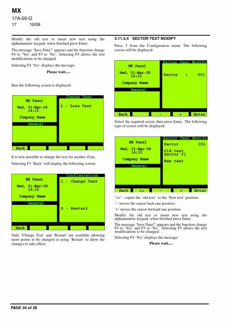
MX17A-05-O17 10/09
Modify the old text or insert new text using thealphanumeric keypad, when finished press Enter.
The message ‘Save Data?’ appears and the function changeF4 to ‘Yes’ and F5 to ‘No’. Selecting F5 allows the textmodifications to be changed.
Selecting F4 ‘Yes’ displays the message:
Please wait.....
then the following screen is displayed:
It is now possible to change the text for another Zone.
Selecting F1 ‘Back’ will display the following screen:
Only ‘Change Text’ and ‘Restart’ are available allowingmore points to be changed or using ‘Restart’ to allow thechanges to take effect.
MX Panel
Wed, 01-Mar-08 14:15
Company Name
General
Back
Change Text
2 - Zone Text
MX Panel
Wed, 01-Mar-08 14:15
Company Name
General
Back
Configuration
1 - Change Text
9 - Restart
PAGE 34 of 38
3.11.3.4 SECTOR TEXT MODIFY
Press 3 from the Configuration menu. The followingscreen will be displayed:
Select the required sector, then press Enter. The followingtype of screen will be displayed:
‘>>’ - copies the ‘old text’ to the ‘New text’ position.
‘-’ moves the cursor back one position.
‘+’ moves the cursor forward one position.
Modify the old text or insert new text using thealphanumeric keypad, when finished press Enter.
The message ‘Save Data?’ appears and the function changeF4 to ‘Yes’ and F5 to ‘No’. Selecting F5 allows the textmodifications to be changed.
Selecting F4 ‘Yes’ displays the message:
Please wait.....
MX Panel
Wed, 01-Mar-08 14:15
Company Name
General
Back
Sector Text Modify
Sector : 001
- + Enter
MX Panel
Wed, 01-Mar-08 14:15
Company Name
General
Back
Sector Text Modify
Sector 001
Old textSector 01
New text
>> - + Enter
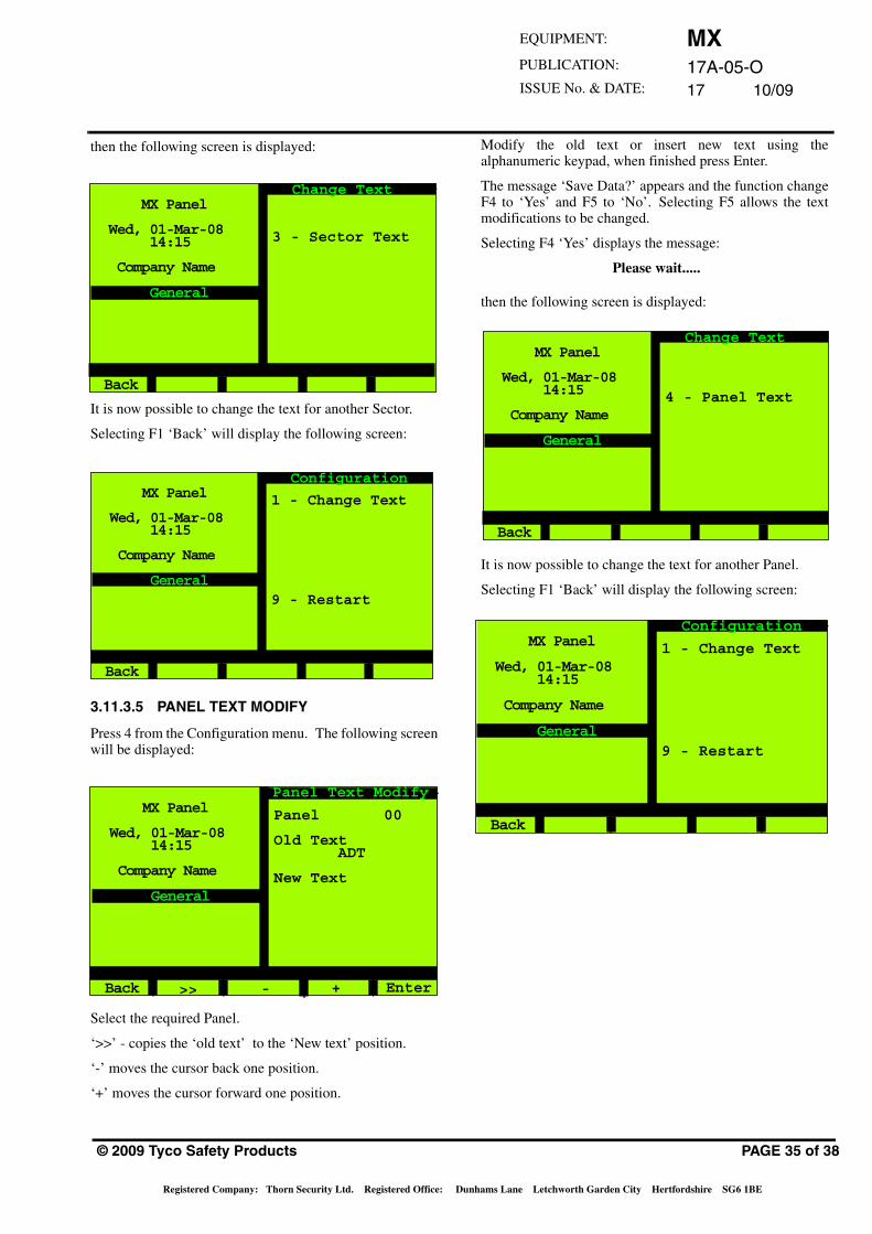
MX17A-05-O17 10/09
EQUIPMENT:
PUBLICATION:
ISSUE No. & DATE:
then the following screen is displayed:
It is now possible to change the text for another Sector.
Selecting F1 ‘Back’ will display the following screen:
3.11.3.5 PANEL TEXT MODIFY
Press 4 from the Configuration menu. The following screenwill be displayed:
Select the required Panel.
‘>>’ - copies the ‘old text’ to the ‘New text’ position.
‘-’ moves the cursor back one position.
‘+’ moves the cursor forward one position.
MX Panel
Wed, 01-Mar-08 14:15
Company Name
General
Back
Change Text
3 - Sector Text
MX Panel
Wed, 01-Mar-08 14:15
Company Name
General
Back
Configuration
1 - Change Text
9 - Restart
MX Panel
Wed, 01-Mar-08 14:15
Company Name
General
Back
Panel Text Modify
Panel 00
Old Text ADT
New Text
Enter>> - +
© 2009 Tyco Safety Products
Registered Company: Thorn Security Ltd. Registered Office: Du
Modify the old text or insert new text using thealphanumeric keypad, when finished press Enter.
The message ‘Save Data?’ appears and the function changeF4 to ‘Yes’ and F5 to ‘No’. Selecting F5 allows the textmodifications to be changed.
Selecting F4 ‘Yes’ displays the message:
Please wait.....
then the following screen is displayed:
It is now possible to change the text for another Panel.
Selecting F1 ‘Back’ will display the following screen:
MX Panel
Wed, 01-Mar-08 14:15
Company Name
General
Back
Change Text
4 - Panel Text
MX Panel
Wed, 01-Mar-08 14:15
Company Name
General
Back
Configuration
1 - Change Text
9 - Restart
PAGE 35 of 38
nhams Lane Letchworth Garden City Hertfordshire SG6 1BE
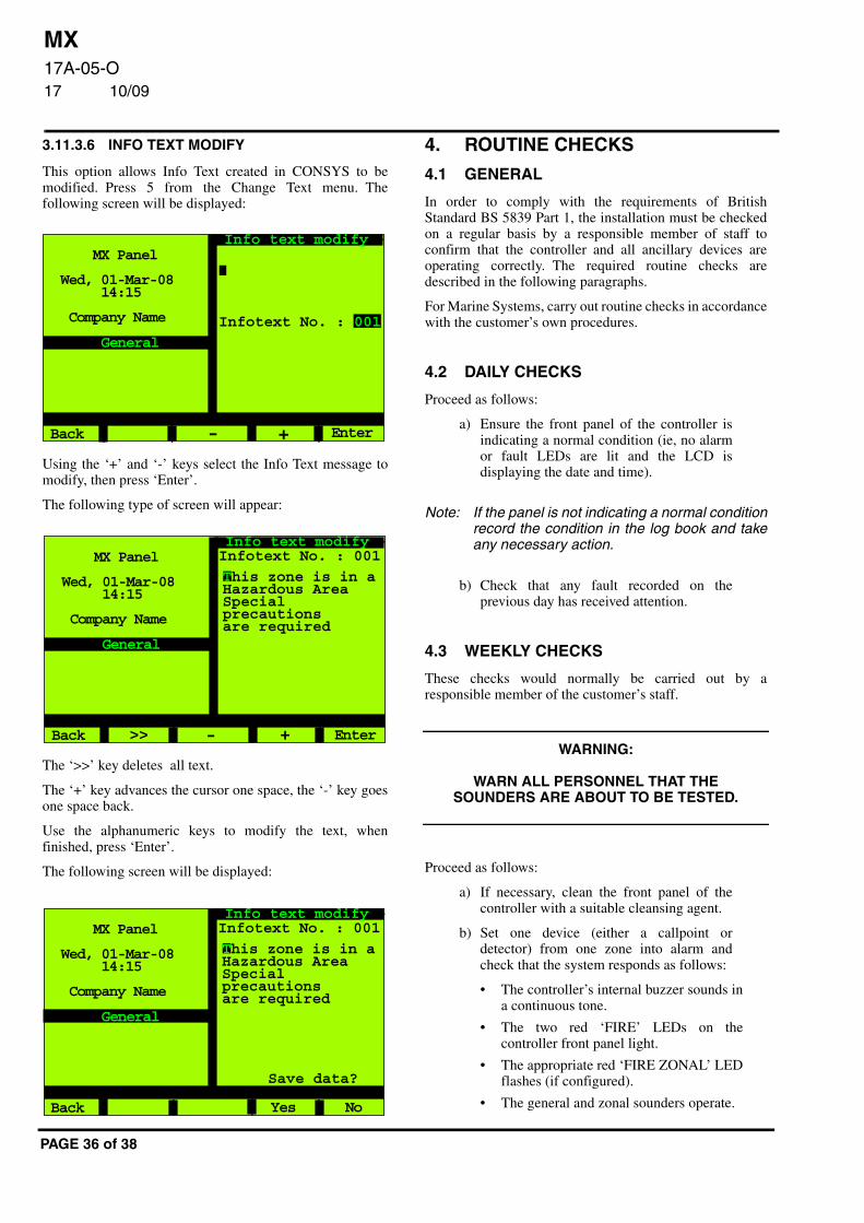
MX17A-05-O17 10/09
3.11.3.6 INFO TEXT MODIFY
This option allows Info Text created in CONSYS to bemodified. Press 5 from the Change Text menu. Thefollowing screen will be displayed:
Using the ‘+’ and ‘-’ keys select the Info Text message tomodify, then press ‘Enter’.
The following type of screen will appear:
The ‘>>’ key deletes all text.
The ‘+’ key advances the cursor one space, the ‘-’ key goesone space back.
Use the alphanumeric keys to modify the text, whenfinished, press ‘Enter’.
The following screen will be displayed:
MX Panel
Wed, 01-Mar-08 14:15
Company Name
General
Back
Info text modify
- + Enter
Infotext No. : 001
MX Panel
Wed, 01-Mar-08 14:15
Company Name
General
Back
Info text modifyInfotext No. : 001
+ Enter
This zone is in aHazardous AreaSpecialprecautionsare required
->>
MX Panel
Wed, 01-Mar-08 14:15
Company Name
General
Back
Info text modifyInfotext No. : 001
Save data?
Yes No
This zone is in aHazardous AreaSpecialprecautionsare required
PAGE 36 of 38
4. ROUTINE CHECKS
4.1 GENERAL
In order to comply with the requirements of BritishStandard BS 5839 Part 1, the installation must be checkedon a regular basis by a responsible member of staff toconfirm that the controller and all ancillary devices areoperating correctly. The required routine checks aredescribed in the following paragraphs.
For Marine Systems, carry out routine checks in accordancewith the customer’s own procedures.
4.2 DAILY CHECKS
Proceed as follows:
a) Ensure the front panel of the controller isindicating a normal condition (ie, no alarmor fault LEDs are lit and the LCD isdisplaying the date and time).
Note: If the panel is not indicating a normal conditionrecord the condition in the log book and takeany necessary action.
b) Check that any fault recorded on theprevious day has received attention.
4.3 WEEKLY CHECKS
These checks would normally be carried out by aresponsible member of the customer’s staff.
WARNING:
WARN ALL PERSONNEL THAT THE SOUNDERS ARE ABOUT TO BE TESTED.
Proceed as follows:
a) If necessary, clean the front panel of thecontroller with a suitable cleansing agent.
b) Set one device (either a callpoint ordetector) from one zone into alarm andcheck that the system responds as follows:
• The controller’s internal buzzer sounds ina continuous tone.
• The two red ‘FIRE’ LEDs on thecontroller front panel light.
• The appropriate red ‘FIRE ZONAL’ LEDflashes (if configured).
• The general and zonal sounders operate.
MX17A-05-O17 10/09
EQUIPMENT:
PUBLICATION:
ISSUE No. & DATE:
• The alphanumeric display gives thelocation of the alarm.
c) Record the device used to initiate the test inthe site log book and reset the controller.
d) Check the condition of the printout on anyprinters attached to the system and replacethe ribbon if it is becoming feint.
e) Ensure that each printer has an adequatesupply of paper.
Any defect should be recorded in the log book andappropriate action taken.
5. CPD INFORMATION
O786
Tyco Safety ProductsDunhams LaneLetchworth SG6 1BEUK
0786-CPD-20840
MX1000, MX4000
Installation Instructions 17A-03-I/CService Instructions 17A-04-S
09
EN 54-2EN 54-4
Control and indicating equipment for firedetection and fire alarm systems forbuildings
Provided options:Alarm counterFault signalsDelays to outputsDependency on more than onealarm signalDisablementTest conditionFire alarm devicesFire alarm routing equipmentAutomatic fire protection equipmentFault warning routing equipmentStandardised I/O interface
Other technical data: see doc. 17A-02-Dheld by the manufacturer
© 2009 Tyco Safety Products
Registered Company: Thorn Security Ltd. Registered Office: Du
O786
Tyco Safety ProductsDunhams LaneLetchworth SG6 1BEUK
0786-CPD-20838
MX2
Installation Instructions 17A-03-I/CService Instructions 17A-04-S
09
EN 54-2
Control and indicating equipment for firedetection and fire alarm systems forbuildings
Provided options:Alarm counterFault signalsDelays to outputsDependency on more than onealarm signalDisablementTest conditionFire alarm devicesFire alarm routing equipmentAutomatic fire protection equipmentFault warning routing equipmentStandardised I/O interface
Other technical data: see doc. 17A-02-Dheld by the manufacturer
PAGE 37 of 38
nhams Lane Letchworth Garden City Hertfordshire SG6 1BE
MX17A-05-O17 10/09
JM/mm
6th November 2009
O786
Tyco Safety ProductsDunhams LaneLetchworth SG6 1BEUK
0786-CPD-20839
T2000
Installation Instructions 17A-03-I/CService Instructions 17A-04-S
09
EN 54-2EN 54-4
Control and indicating equipment for firedetection and fire alarm systems forbuildings
Provided options:Alarm counterFault signalsTotal loss of power supplyDelays to outputsDependency on more than onealarm signalDisablementTest conditionFire alarm devicesFire alarm routing equipmentAutomatic fire protection equipmentFault warning routing equipmentStandardised I/O interface
Other technical data: see doc. 17A-02-Dheld by the manufacturer
PAGE 38 of 38
Recommended