Embed Size (px)
Citation preview

8/6/2019 T2000 DataSheet 2004
http://slidepdf.com/reader/full/t2000-datasheet-2004 1/4
7/14/2004 Page 1 T2000 DataSheet 2004Subject to change without. notice
T/2000
Mul t i -Func t ion Syst em for Test ing
Subst at i on Equipm ent
CT, VT, PT and Transduc er Tes t ing
H V Diagnosti cs, Inc271 Rope Mil l Pkwy, Ste 2Woodstock, GA 30188Phone: 678-445-2555 Fax: 678-445-2557E-mail: [email protected]
8/6/2019 T2000 DataSheet 2004
http://slidepdf.com/reader/full/t2000-datasheet-2004 2/4
7/14/2004 Page 2 T2000 DataSheet 2004Subject to change without. notice
HV Diagnostics Inc. 271 Rope Mill Pkwy, Ste 2
Woodstock, GA 30188
Web:www.hvdiagnostics.com
Phone: 678-445-2555
Fax: 678-445-2557
Email: [email protected] Suppliers of:
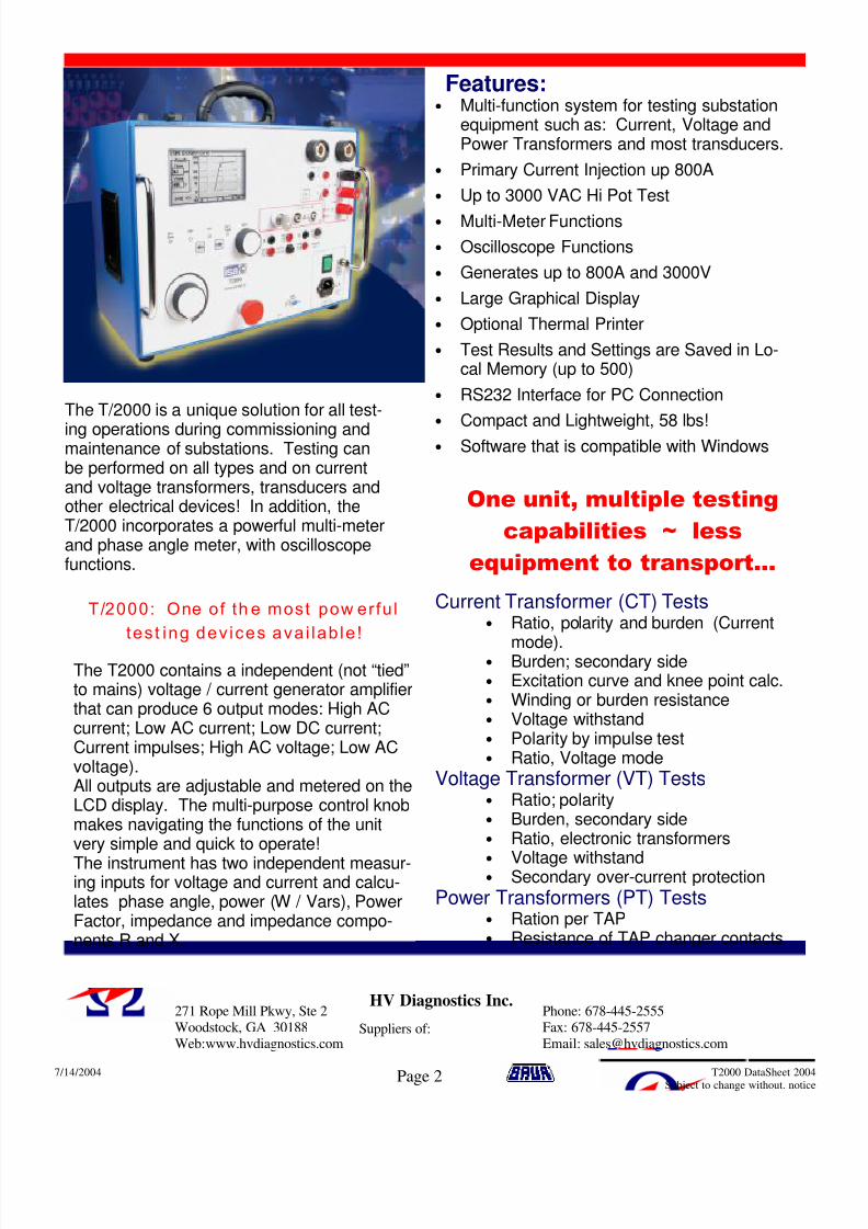
• Multi-function system for testing substationequipment such as: Current, Voltage andPower Transformers and most transducers.
• Primary Current Injection up 800A
• Up to 3000 VAC Hi Pot Test
• Multi-Meter Functions
• Oscilloscope Functions
• Generates up to 800A and 3000V
• Large Graphical Display
• Optional Thermal Printer
• Test Results and Settings are Saved in Lo-cal Memory (up to 500)
• RS232 Interface for PC Connection
• Compact and Lightweight, 58 lbs!
• Software that is compatible with Windows
Features:
The T/2000 is a unique solution for all test-
ing operations during commissioning andmaintenance of substations. Testing canbe performed on all types and on currentand voltage transformers, transducers andother electrical devices! In addition, theT/2000 incorporates a powerful multi-meterand phase angle meter, with oscilloscopefunctions.
One unit, multiple testing
capabilities ~ less
equipment to transport...
Current Transformer (CT) Tests• Ratio, polarity and burden (Current
mode).• Burden; secondary side• Excitation curve and knee point calc.• Winding or burden resistance• Voltage withstand• Polarity by impulse test• Ratio, Voltage mode
Voltage Transformer (VT) Tests• Ratio; polarity • Burden, secondary side • Ratio, electronic transformers •
Voltage withstand • Secondary over-current protection
Power Transformers (PT) Tests• Ration per TAP• Resistance of TAP changer contacts
The T2000 contains a independent (not “tied”to mains) voltage / current generator amplifierthat can produce 6 output modes: High ACcurrent; Low AC current; Low DC current;Current impulses; High AC voltage; Low ACvoltage).All outputs are adjustable and metered on theLCD display. The multi-purpose control knobmakes navigating the functions of the unitvery simple and quick to operate!
The instrument has two independent measur-ing inputs for voltage and current and calcu-lates phase angle, power (W / Vars), PowerFactor, impedance and impedance compo-nents R and X.
T/2000: One of th e most pow erfu l
tes t ing dev ices ava i lab le !

8/6/2019 T2000 DataSheet 2004
http://slidepdf.com/reader/full/t2000-datasheet-2004 3/4
7/14/2004 Page 3 T2000 DataSheet 2004Subject to change without. notice
HV Diagnostics Inc. 271 Rope Mill Pkwy, Ste 2
Woodstock, GA 30188
Web:www.hvdiagnostics.com
Phone: 678-445-2555
Fax: 678-445-2557
Email: [email protected] Suppliers of:
Other Metering Performed and Displayed:
• Active, Reactive, and Apparent Power
• Power Factor• Impedance (Z) and impedance com-
ponents (R/X)
• Frequency Hz• Phase Angle• Resistance
• Current and Waveform Display
Software X.Pro-3000When the PC is connected, settings can be created and transferred into T/2000 using X.PRO-3000.X.PRO-3000 is a user friendly software that allows via a graphical interface, to control the set-upof T/2000 and to download test results.X.PRO-3000 is also a powerful report editor that allows the user create professional Test Reportsthat be exported in Access format.
Optional AccessoriesAccessories for CT Testing• Mains Supply Cable, 6’ long• Grounding cable, 12’ long, terminated on
one end with a banana plug, and on theother end with an earth connection clamp
• High voltage connection cables, 12’ long,5kV with earth screen. Terminated on bothends with HV connectors.
• Clamps for the HV connection• Clamps to connect low voltage or low cur-
rent or measurements• Cable for low voltage or low current con-
nection, shielded, 12’ long. Terminated onone end with the measurement connector,and on the other with two banana plugs
Additional Accessories:• Interface cable for RS232 port• High Current connection cables, 12’ long.
Terminated on one end with the high cur-rent connector; and on the other with thehigh current clamp
• Low current connection cables, 12’ long.Terminated on both ends with bananaplugs.
• Voltage outputs (4 cables: 2 red and 2black)
• Measurement inputs (4 cables: 2 red and 2black)
• The instrument comes complete with thefollowing: user manual, spare fuses (no.5),T16A.
Software:X.PRO-3000 with user manual
Optional Accessories• Thermal printer
• Transport case • Current Clamp: The current clamp avoids
opening the secondary current circuit whenperforming the primary test of CT burden
Ordering Information:Two Models of the T2000 are available
T2000H……..3000VAC, 200mA continuous.6A (1 minute)
T2000L……...1200VAC, 500mA continuous1.5A (1 minute)

8/6/2019 T2000 DataSheet 2004
http://slidepdf.com/reader/full/t2000-datasheet-2004 4/4
7/14/2004 Page 4 T2000 DataSheet 2004Subject to change without. notice
HV Diagnostics Inc.271 Rope Mill Pkwy, Ste 2
Woodstock, GA 30188
Web:www.hvdiagnostics.com
Phone: 678-445-2555
Fax: 678-445-2557
Email: [email protected] Suppliers of: