Photo: Reidar Hahn
Erk JENSEN, CERN
Superconducting RF Systems IIITechniques and Technologies

Photo: Reidar Hahn
2-M
ar-2
01
8Su
per
con
du
ctin
g R
F Sy
stem
s III
C
AS
Zuri
ch
2
Cavity fabrication techniques
Photo: Reidar Hahn
Materials
2-M
ar-2
01
8Su
per
con
du
ctin
g R
F Sy
stem
s III
C
AS
Zuri
ch
3
• Selection criteria• Electrical conductivity
• Secondary emission yield (SEY)
• mechanical stiffness/hardness (at cryogenic 𝑇)
• thermal conductivity, thermal expansion
• machining & joining techniques
• vacuum tight, low outgassing rate
• creep resistance,
• magnetic permeability
• radiation hardness
• fatigue stress
• …
• Important: specify what you need and what you can measure/control at reception!

Photo: Reidar Hahn
Niobium
2-M
ar-2
01
8Su
per
con
du
ctin
g R
F Sy
stem
s III
C
AS
Zuri
ch
4
• Magnets use NbTi or Nb3Sn, SC Cavities use mainly Nb!
• Pure Nb has a high critical magnetic field (𝐻𝑐 = 200 mT)
• Nb has a high transition temperature (𝑇𝑐 = 9.3 K).
• It is chemically inert (surface covered by oxide layer)
• It can be machined and deep-drawn
• It is available as bulk and sheet material in any size, fabricated by forging and rolling
• Large grain sizes (often favoured) obtained by e-beam melting (EBM).
• Instead of bulk or sheet Nb, Nb can also be coated (e.g. by sputtering) on Cu – CERN has built the LEP, LHC and ISOLDE cavities with this technique. Advantages: thermal stability, material cost, optimisation of 𝑅𝐵𝐶𝑆 possible; disadvantages: difficult technology to master, lower 𝑄0.
Nb ingot after EBM at Heraeus (D)
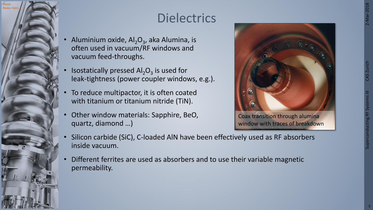
Photo: Reidar Hahn
Dielectrics
2-M
ar-2
01
8Su
per
con
du
ctin
g R
F Sy
stem
s III
C
AS
Zuri
ch
5
• Aluminium oxide, Al2O3, aka Alumina, isoften used in vacuum/RF windows andvacuum feed-throughs.
• Isostatically pressed Al2O3 is used for leak-tightness (power coupler windows, e.g.).
• To reduce multipactor, it is often coated with titanium or titanium nitride (TiN).
• Other window materials: Sapphire, BeO,quartz, diamond …)
• Silicon carbide (SiC), C-loaded AlN have been effectively used as RF absorbers inside vacuum.
• Different ferrites are used as absorbers and to use their variable magnetic permeability.
Coax transition through alumina window with traces of breakdown

Photo: Reidar Hahn
Fabrication of Nb sheets at 2-M
ar-2
01
8Su
per
con
du
ctin
g R
F Sy
stem
s III
C
AS
Zuri
ch
6
L-He
Nb ingot
Pressing
1st EB
melting
2nd, 3rd … EB
melting
Separate
from base
plate
Forging
Milling
Rolling
Polishing
Rolling
Cutting
Annealing
Levering
Chemical
polishing
Inspections: (ICP-AES,
Gas analysis, RRR, grain
size, hardness tensile
stress …)

Photo: Reidar Hahn
2-M
ar-2
01
8Su
per
con
du
ctin
g R
F Sy
stem
s III
C
AS
Zuri
ch
7
• Forging, pressing, deep drawing, …
• Spinning, planing, rolling, …
• lapping, polishing, electropolishing, …
• Electro-forming, hydroforming, explosion forming
• Powder metal techniques, additive manufacturing (3-D printing)
• Sputtering
• Backward extrusion
• Necking
Other forming techniques
back-extruded Nb tubes for E-XFEL
courtesy: Waldemar Singer/DESYNecking machine at KEK for fabrication of multi-cell seamless cavities

Photo: Reidar Hahn
Joining techniques
2-M
ar-2
01
8Su
per
con
du
ctin
g R
F Sy
stem
s III
C
AS
Zuri
ch
8
TIG welding
double joint: inner for vacuum,outer for mechanical stability
Electron beam (EB) welding
Microstructure of the EB welding areagrain size (50 ÷ 2000) μm

Photo: Reidar Hahn
Established cavity fabrication technique
2-M
ar-2
01
8Su
per
con
du
ctin
g R
F Sy
stem
s III
C
AS
Zuri
ch
9
Half cells are
shaped by deep
drawing.
Dumb bells are
assemled by
electron beam
welding.
After proper cleaning
eight dumb bells and
two end group sections
welded by electron
beam together
Important: clean conditions on all stepsshape accuracy, preparation and EB welding courtesy: Waldemar Singer/DESY

Photo: Reidar Hahn
Advances in SCRF Technology
Preparing for EP (inserting cathode)
Clean room assembly (JLAB)
Photos: Rongli Geng
C. Antoine: CAS SC 2013
Sup
erco
nd
uct
ing
RF
Syst
ems
III
CA
S Zu
rich
10
2-M
ar-2
01
8

Photo: Reidar Hahn
2-M
ar-2
01
8Su
per
con
du
ctin
g R
F Sy
stem
s III
C
AS
Zuri
ch
11
Parts in a cavity (XFEL 9-cell, courtesy DESY)
Degreasing
Degreasing,BCP chemistry & in clean room

Photo: Reidar Hahn
2-M
ar-2
01
8Su
per
con
du
ctin
g R
F Sy
stem
s III
C
AS
Zuri
ch
12
XFEL recipe (EP scheme)LCLS-II recipe
Post processing flow chart (LCLS-II vs. E-XFEL)

Photo: Reidar Hahn
2-M
ar-2
01
8Su
per
con
du
ctin
g R
F Sy
stem
s III
C
AS
Zuri
ch
13
Clean-rooms – design and use

Photo: Reidar Hahn
2-M
ar-2
01
8Su
per
con
du
ctin
g R
F Sy
stem
s III
C
AS
Zuri
ch
14
From ISO standard:
• A room in which the concentration of airborne particles is controlled, and which is constructed and used in a manner to minimize the introduction, generation, and retention of particles inside the room and in which other relevant parameters, e.g. temperature, humidity, and pressure, are controlled as necessary.
• “Clean-room” is only defined for room and air, it is your job not to mess it up as you are the dirtiest thing in the room and the items you bring into the room are the next dirtiest.
What is a clean-room?
This is what you look like to the cleanroom

Photo: Reidar Hahn
La
2-M
ar-2
01
8Su
per
con
du
ctin
g R
F Sy
stem
s III
C
AS
Zuri
ch
15
Types of clean-rooms
Laminar flow room Turbulent flow room
Limited to ISO 6 applications, where a large amount of particles is produced.

Photo: Reidar Hahn
2-M
ar-2
01
8Su
per
con
du
ctin
g R
F Sy
stem
s III
C
AS
Zuri
ch
16
ISO classifications
ISO 1: Only for very specialized applications and usually very small.ISO 2/3: Micro-electric manufacturing (usually mini environments and robots only).ISO 4/5: SCRF cavity assembly.
ISO 6/7: Pass-through, gowning as well as clean parts.
Sizes:Hair 50-150 µmPollen 7 -100 µmDust 0.1-100 µmSneeze particles 10-300 µmBacteria 1.0-10 µmBest human vision ~10’s µm

Photo: Reidar Hahn
2-M
ar-2
01
8Su
per
con
du
ctin
g R
F Sy
stem
s III
C
AS
Zuri
ch
17
Particle counters
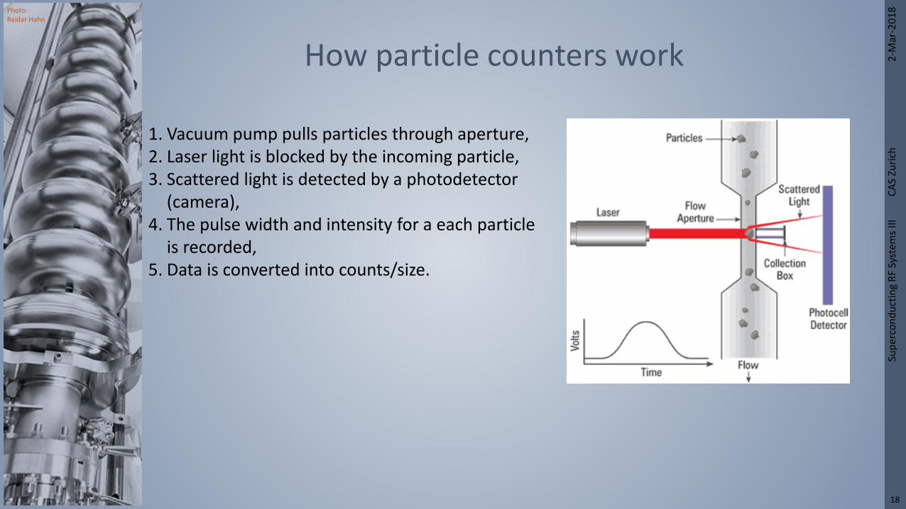
Photo: Reidar Hahn
2-M
ar-2
01
8Su
per
con
du
ctin
g R
F Sy
stem
s III
C
AS
Zuri
ch
18
1. Vacuum pump pulls particles through aperture,2. Laser light is blocked by the incoming particle,3. Scattered light is detected by a photodetector
(camera),4. The pulse width and intensity for a each particle
is recorded,5. Data is converted into counts/size.
How particle counters work

Photo: Reidar Hahn
2-M
ar-2
01
8Su
per
con
du
ctin
g R
F Sy
stem
s III
C
AS
Zuri
ch
19
• Full-scale Schlieren flow visualization stills – body flow examples (“differential diffraction images”)
Why we wear clean-room suits
Vertical flow from human (100K particle per minute)
Open mouth cough in standard room (wear mask!) cough produce over 1M particles!
Fully suited person in clean room
Don’t lean over parts!

Photo: Reidar Hahn
2-M
ar-2
01
8Su
per
con
du
ctin
g R
F Sy
stem
s III
C
AS
Zuri
ch
20
• Everyone in clean-room must wear full-body “bunny suit”!
• All suits are clean to ISO-4 standards
• Suits are double bagged (large single bag and smaller item bags)
• Suits are made out of 99% polyester/1% carbon (carbon is added as a drain for static build up)
• Suits are changed out at least once a week (some do every day), with extra change outs when contamination is detected (user discretion).
Clean-room suits (example JLAB)

Photo: Reidar Hahn
2-M
ar-2
01
8Su
per
con
du
ctin
g R
F Sy
stem
s III
C
AS
Zuri
ch
21
• Wash and dry hands thoroughly in rest room – you should probably use the facilities as well,
• Check shoes for dirt, dirty shoes are not allowed,
• Use shoe cleaner to remove dust from shoes and then step on sticky pad until no new dirty is being removed from shoes,
• Only 1 person is allowed in the entry-way at a time,
• External doors are not allowed open when gowning door and/or curtain is open.
Clean-room protocol – before entryGowning room door &
isolation curtain
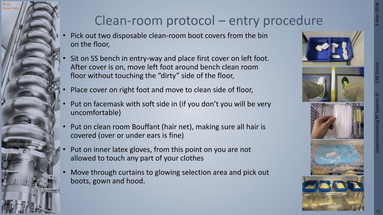
Photo: Reidar Hahn
2-M
ar-2
01
8Su
per
con
du
ctin
g R
F Sy
stem
s III
C
AS
Zuri
ch
22
• Pick out two disposable clean-room boot covers from the bin on the floor,
• Sit on SS bench in entry-way and place first cover on left foot. After cover is on, move left foot around bench clean room floor without touching the “dirty” side of the floor,
• Place cover on right foot and move to clean side of floor,
• Put on facemask with soft side in (if you don’t you will be very uncomfortable)
• Put on clean room Bouffant (hair net), making sure all hair is covered (over or under ears is fine)
• Put on inner latex gloves, from this point on you are not allowed to touch any part of your clothes
• Move through curtains to glowing selection area and pick out boots, gown and hood.
Clean-room protocol – entry procedure

Photo: Reidar Hahn
2-M
ar-2
01
8Su
per
con
du
ctin
g R
F Sy
stem
s III
C
AS
Zuri
ch
23
• Remove outer glove and dispose of – do not let inner glove touch trash,
• Remove boot covers and do not allow covers to touch floor,
• Remove hood by pulling inside out,
• Remove covers without letting them touch floor (legs are most difficult, arms are most important),
• Hang on designated rack with booties and head over buttoned to suit
Clean-room protocol – un-gowning

Photo: Reidar Hahn
2-M
ar-2
01
8Su
per
con
du
ctin
g R
F Sy
stem
s III
C
AS
Zuri
ch
24
• Special wipers – fabricated in ISO3
• No normal paper allowed in clean-room – there exists 100% synthetic cleanroom bond paper, cellulose free.
• Certified gloves, shoe covers …
Clean-room consumables

Photo: Reidar Hahn
2-M
ar-2
01
8Su
per
con
du
ctin
g R
F Sy
stem
s III
C
AS
Zuri
ch
25
Example: JLAB clean-room

Photo: Reidar Hahn
2-M
ar-2
01
8Su
per
con
du
ctin
g R
F Sy
stem
s III
C
AS
Zuri
ch
26
• All personnel entering load-lock must wear hair net, face mask, shoe cover, gloves and lab coat, put on in the order listed above. Lab coat should not be touched by ungloved hands (or dirty gloves),
• Once shoe covers are on, you are not allowed to stand on floor, only sticky mat!
• Entry is only allowed when inner clean room doors are closed and load-lock is unoccupied,
• Spend as little time as possible in load lock!
Clean-room load-lock entry (for parts)

Photo: Reidar Hahn
2-M
ar-2
01
8Su
per
con
du
ctin
g R
F Sy
stem
s III
C
AS
Zuri
ch
27
Ultrapure water (UPW) system

Photo: Reidar Hahn
2-M
ar-2
01
8Su
per
con
du
ctin
g R
F Sy
stem
s III
C
AS
Zuri
ch
28
General description
• Water devoid of any dissolved, suspended, organic or inorganic impurities
• In reality water is never 100% devoid of all impurities
• … so devoid to the detection limits of analytical methods:• Detection limits are often expressed in
• PPM: parts per million (mg/l)
• PPB: Parts per Billion (µg/L) – most relevant for SRF applications
• PPT: Parts per Trillion (ng/L)
• PPQ: Parts per quadrillion (pg/ml)
More meaningful definition:
• Water that has been purified to a specific standard or quality specification
• … probably as many definitions as there are specifications…
What is ultrapure water?
1 ppb is roughly the equivalent of one drop in 250 chemical drums!

Photo: Reidar Hahn
2-M
ar-2
01
8Su
per
con
du
ctin
g R
F Sy
stem
s III
C
AS
Zuri
ch
29
• Start with the end in mind – UPW specification!
• Quantify the quality of the city drinking water
• Producing UPW is a series of separation steps• Remove the dirt, sand and silt,
• Remove the larger organics and the chemicals the city adds to control harmful bacteria,
• Remove the dissolved mineral salts,
• Remove the dissolved solids,
• Remove the bacteria and microspores,
• Remove the very small particles,
• Repeat until ppb levels are achieved
From tab water to ultrapure water

Photo: Reidar Hahn
2-M
ar-2
01
8Su
per
con
du
ctin
g R
F Sy
stem
s III
C
AS
Zuri
ch
30
UPW system process diagram
Laura Popielarski, Cavity Processing and Cleanroom Techniques, Whistler 2015

Photo: Reidar Hahn
2-M
ar-2
01
8Su
per
con
du
ctin
g R
F Sy
stem
s III
C
AS
Zuri
ch
31
Parameter Specification typically obtained
Resistivity > 18.2 ΤMΩ cm2 18.22
Total organic carbon (TOC) ≤ 2 ppb 1.35 ppb
Particle counts weekly average max.
Channel 1: 0.05…0.1 μm ≤ 2000 counts/l 6.35 120
Channel 2: 0.1…0.15 μm ≤ 350 counts/l 1.33 19
Channel 3: 0.15…0.2 μm ≤ 350counts/l 0 0
Channel 4: > 0.2 μm ≤ 20 counts/l 0 1
Temperature [℃] Pressure [𝐛𝐚𝐫] Flow [𝐥/𝐦𝐢𝐧]
Ambient UPW 21 4.83 336
Hot UPW 80 4.55 64
Ultrapure water specification & experience (JLAB)

Photo: Reidar Hahn
2-M
ar-2
01
8Su
per
con
du
ctin
g R
F Sy
stem
s III
C
AS
Zuri
ch
32
Cavity Process Tools• Horizontal and Vertical Electropolishing (HEP and VEP)
• Post EP fill and dump cycles, ≈ 21℃• Final rinse through cavity to quality, ≈ 21℃
• Buffered Chemical Polish (BCP)• Post EP fill and dump cycles, ≈ 21℃• Final rinse through cavity to quality, ≈ 21℃ and ≈ 80℃ (hot UPW)
• High Pressure Rinsing (HPR)• Typical pressure is 83 bar, temperature is ≈ 21℃• Flow depends on pressure and nozzle configuration
UHV Cleaning• All ultrasonic cleaning stations
• UPW + Surfactants (Micro-90 and Liquinox)• UPW only• Component cleaning prior to cavity assembly • Parts clean prior to electron beam welding
Ultrapure water – where and how to use it

Photo: Reidar Hahn
2-M
ar-2
01
8Su
per
con
du
ctin
g R
F Sy
stem
s III
C
AS
Zuri
ch
33
Cavity preparation

Photo: Reidar Hahn
2-M
ar-2
01
8Su
per
con
du
ctin
g R
F Sy
stem
s III
C
AS
Zuri
ch
34
Defects are unavoidable with present techniques
Aliaksandr Navitski “grinding and CBP at DESY”, 2014

Photo: Reidar Hahn
2-M
ar-2
01
8Su
per
con
du
ctin
g R
F Sy
stem
s III
C
AS
Zuri
ch
35
Cavity grinding – Ettore Zanon 1
http://accelconf.web.cern.ch/accelconf/srf2015/posters/mopb094_poster.pdf

Photo: Reidar Hahn
2-M
ar-2
01
8Su
per
con
du
ctin
g R
F Sy
stem
s III
C
AS
Zuri
ch
36
Cavity grinding – Ettore Zanon 2
http://accelconf.web.cern.ch/accelconf/srf2015/posters/mopb094_poster.pdf

Photo: Reidar Hahn
2-M
ar-2
01
8Su
per
con
du
ctin
g R
F Sy
stem
s III
C
AS
Zuri
ch
37
Centrifugal Barrel Polishing – CBP 1

Photo: Reidar Hahn
2-M
ar-2
01
8Su
per
con
du
ctin
g R
F Sy
stem
s III
C
AS
Zuri
ch
38
Centrifugal Barrel Polishing – CBP 2Tumbling machine at FNAL
Medias are tumbled inside. The grey cones (far left) are a plastic with aluminum silicate, used for bulk removal. The powder blue media (second from left) are ceramic abrasives, useful as a first-pass media. A hardwood cut into small cubes (far right) is also a useful abrasive.
The tumbling machine can hold two 9-cell accelerating cavities, rotating them up to 115 rpm. The rinsing device (right) washes the media out. Cavities must be absolutely free of any extraneous material after tumbling.
Mirror-like finish can be achieved
Laura Popielarski, Cavity Processing and Cleanroom Techniques, Whistler 2015

Photo: Reidar Hahn
2-M
ar-2
01
8Su
per
con
du
ctin
g R
F Sy
stem
s III
C
AS
Zuri
ch
39
• Cratex rubber-bonded abrasives• Medium to extra-fine (240 to 400 grit)
• 3M wheel buffing wheels• Gray CFFB 3M wheel (600 grit)
• Red CFFB 3M wheel (400 grit)
• Scotch-Brite pad• 7445 - White pad (1000) 1200-1500 grit
• 7448 - Light Grey (600-800) 800 grit.
• 6448 – Green (600) 600 grit
• 7447 - Maroon pad (320-400) 320 grit
• 6444 - Brown pad (280-320) 240 grit
• Never use sand paper with grit larger than 800 grit!
Grinding tools
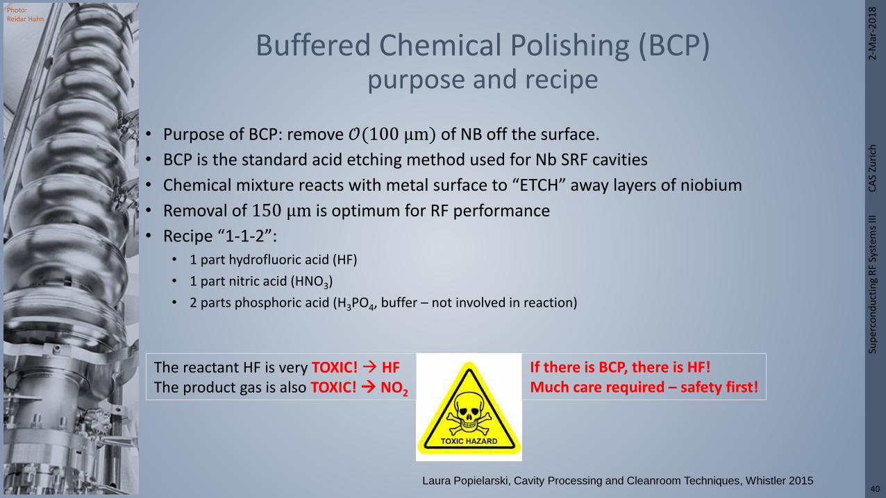
Photo: Reidar Hahn
2-M
ar-2
01
8Su
per
con
du
ctin
g R
F Sy
stem
s III
C
AS
Zuri
ch
40
• Purpose of BCP: remove 𝒪(100 μm) of NB off the surface.
• BCP is the standard acid etching method used for Nb SRF cavities
• Chemical mixture reacts with metal surface to “ETCH” away layers of niobium
• Removal of 150 μm is optimum for RF performance
• Recipe “1-1-2”:• 1 part hydrofluoric acid (HF)
• 1 part nitric acid (HNO3)
• 2 parts phosphoric acid (H3PO4, buffer – not involved in reaction)
Buffered Chemical Polishing (BCP) purpose and recipe
The reactant HF is very TOXIC! HFThe product gas is also TOXIC! NO2
If there is BCP, there is HF!Much care required – safety first!
Laura Popielarski, Cavity Processing and Cleanroom Techniques, Whistler 2015
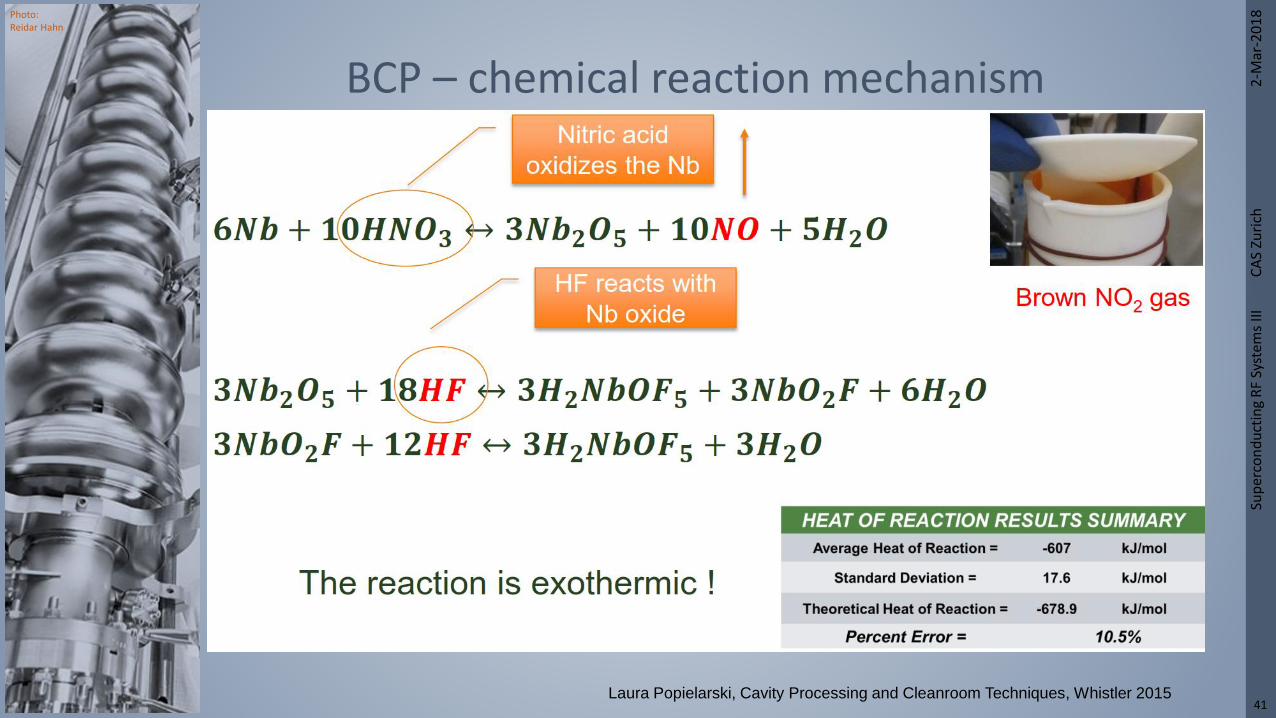
Photo: Reidar Hahn
2-M
ar-2
01
8Su
per
con
du
ctin
g R
F Sy
stem
s III
C
AS
Zuri
ch
41
BCP – chemical reaction mechanism
Laura Popielarski, Cavity Processing and Cleanroom Techniques, Whistler 2015

Photo: Reidar Hahn
2-M
ar-2
01
8Su
per
con
du
ctin
g R
F Sy
stem
s III
C
AS
Zuri
ch
42
• Best performance reached with 150…200 μm removal
• If more material is removed it becomes thin and mechanically less stable.
• Additional etching does not improve surface roughness
BCP – how much to remove?
Kenji Saito, Lecture note Tokyo University 2011 I. Malloch et al., “Study on particulate retention on polished Niobium
surfaces after BCP etching”, PAC2013
Laura Popielarski, Cavity Processing and Cleanroom Techniques, Whistler 2015

Photo: Reidar Hahn
2-M
ar-2
01
8Su
per
con
du
ctin
g R
F Sy
stem
s III
C
AS
Zuri
ch
43
• Remember Slater’s theorem: 𝜔−𝜔0
𝜔=
Δ𝑉 𝜇0 𝐻02−𝜀 𝐸0
2 ⅆ𝑉
𝑉𝜇0 𝐻0
2+𝜀 𝐸02 ⅆ𝑉
:
• Surface removal in regions of electric field will shift 𝑓 down – in regions of magnetic field will shift 𝑓 up – this can be used by differential etching!
Differential BCP for frequency correction
Δ𝑓 > 0 Δ𝑓 < 0
Laura Popielarski, Cavity Processing and Cleanroom Techniques, Whistler 2015

Photo: Reidar Hahn
2-M
ar-2
01
8Su
per
con
du
ctin
g R
F Sy
stem
s III
C
AS
Zuri
ch
44
• EP applied to reduce surface roughness and create smoother surface
• A DC bias results in a stronger removal near protruding surface features, less in recesses (field enhancement, increased currents on corners and burrs – anodic levelling).
Electropolishing – EP
Overall: 2 Nb + 10 HF + 2 H2O 2 H2NbOF5+ 5 H2
Laura Popielarski, Cavity Processing and Cleanroom Techniques, Whistler 2015

Photo: Reidar Hahn
2-M
ar-2
01
8Su
per
con
du
ctin
g R
F Sy
stem
s III
C
AS
Zuri
ch
45
• EP delivers very smooth surfaces.
• On EP samples, surface roughness drops below 1 μm after 150 μm of material removed (L. Lilje, Improved Surface Treatment of SC TESLA Cavities)
• The main difference between BCP and EP is the smoothening of the grain boundaries
The results of EP
Laura Popielarski, Cavity Processing and Cleanroom Techniques, Whistler 2015
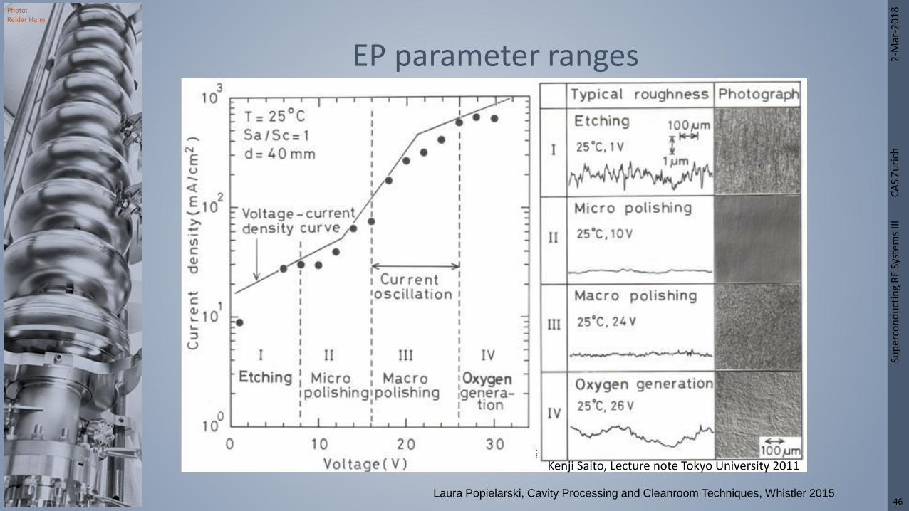
Photo: Reidar Hahn
2-M
ar-2
01
8Su
per
con
du
ctin
g R
F Sy
stem
s III
C
AS
Zuri
ch
46
EP parameter ranges
Kenji Saito, Lecture note Tokyo University 2011
Laura Popielarski, Cavity Processing and Cleanroom Techniques, Whistler 2015

Photo: Reidar Hahn
2-M
ar-2
01
8Su
per
con
du
ctin
g R
F Sy
stem
s III
C
AS
Zuri
ch
47
• Clearly observed 𝑄0 drop after Nb soak around 100 K for 1+ hours.
• 𝑄0 drop (also referred to as Q-disease) is due to hydrogen uptake during processing.
• Fast cool-down of Nb < 1 hr is required to avoid the 𝑄0 drop.
• Hydrogen degasification proven to eliminate the 𝑄0 drop even during slow cool down.
• Effective degassing starts ≈ 600 ℃.
• Cavities fired in vacuum furnace for 10 hrs at 600 ℃ at 10−5 mbar after 12hrs “soak” at 350 ℃ .
• Cavity must be degreased and dry!
• Furnace must be kept clean and dry, and located in a clean zone
Why heat treatment?
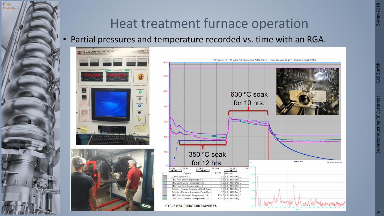
Photo: Reidar Hahn
2-M
ar-2
01
8Su
per
con
du
ctin
g R
F Sy
stem
s III
C
AS
Zuri
ch
48
• Partial pressures and temperature recorded vs. time with an RGA.
Heat treatment furnace operation

Photo: Reidar Hahn
2-M
ar-2
01
8Su
per
con
du
ctin
g R
F Sy
stem
s III
C
AS
Zuri
ch
49
• Bake at 100…150 ℃ under UHV for > 24 h has beneficial effects on the BCS surface resistance and the high field Q-drop.
• It has been related to oxygen diffusion into the niobium, causing changes of the structure niobium/oxide interface on a nanometer scale.
• Has proven effective for electropolished elliptical cavities.
120 ℃ “low temperature bake”

Photo: Reidar Hahn
2-M
ar-2
01
8Su
per
con
du
ctin
g R
F Sy
stem
s III
C
AS
Zuri
ch
50
• 70 to 100 bar at point of use,
• Motion rotation and translation, avoid spiral affect,
• Materials Clean-room and UPW compatible, low friction – smooth surface,
• Duration Depends on cavity type and surface area, LCLS-II/XFEL vendors final rinse (6 passes, 12hours),
• Post-Rinse dry in ISO 5/4 cleanroom, away from all movement or people,
• Ideally cabinet is pressurized above cleanroom levels to ensure particle from operator do not move towards wet cavity,
• Most designed for elliptical cavities – I will show alternatives – making non-elliptical geometry HPR difficult.
High Pressure Rinsing (HPR)
https://journals.aps.org/prab/pdf/10.1103/PhysRevAccelBeams.20.042004

Photo: Reidar Hahn
2-M
ar-2
01
8Su
per
con
du
ctin
g R
F Sy
stem
s III
C
AS
Zuri
ch
51
Existing HPR cabinets
AES (2009) ORNL (2012) CERN (2013) JLAB (2015)

Photo: Reidar Hahn
2-M
ar-2
01
8Su
per
con
du
ctin
g R
F Sy
stem
s III
C
AS
Zuri
ch
52
Features of JLAB HPR system

Photo: Reidar Hahn
2-M
ar-2
01
8Su
per
con
du
ctin
g R
F Sy
stem
s III
C
AS
Zuri
ch
53
Wand head/nozzles• Wand alignment to table within 0.5 mm at 1.8 m! • Wand Head (Standard)
• Based on ORNL design for stability,• JLAB head has smaller OD,• 6 individual nozzles spaced at 120° apart, angled up/down.• JLAB has two designs (60° and 75°)
• Nozzles• Spray.com• TM-TC1501-SS = 15° fan, .75 GPM @ 1000psi • TM-TC25015-SS = 25° fan, .75 GPM @ 1000psi
• Nozzle in HPRv2 today = 75° flat with 15° fan
Points to consider for nozzle design:• Coverage• Fan spray• Impact force• Testing & modelling

Photo: Reidar Hahn
2-M
ar-2
01
8Su
per
con
du
ctin
g R
F Sy
stem
s III
C
AS
Zuri
ch
54
• Total Organic Carbon (TOC) content measurement
• Visual inspection and white poly wipe
• Water break free test
• Clean gas spray & count
• Surface particle counts
• UV light inspection
• Residual gas analysis
Tests to check cleanliness
CLEAN DIRTY

Photo: Reidar Hahn
2-M
ar-2
01
8Su
per
con
du
ctin
g R
F Sy
stem
s III
C
AS
Zuri
ch
55
• Single cell cavity are allowed to dry > 3 hours before assembly.
• Multi-cell cavities are dried overnight (>12 hours) before assembly.
• All possible ports on the cavity is open for drying,
• For final assembly only bottom port is left open.
Cavity drying (after HPR)

Photo: Reidar Hahn
2-M
ar-2
01
8Su
per
con
du
ctin
g R
F Sy
stem
s III
C
AS
Zuri
ch
56
• All parts are cleaned to remove all grease, particles, and possible other forms of contamination,
• Ultrasonically cleaned for 30 min in detergent and then rinsed with ultra pure water,
• Dried in flow hood and/or blow dry with filtered ionized nitrogen,
• Bagged in antistatic clean room bags,
• Bagged parts are placed in pass-through,
• Larger parts are not bagged but dried in pass-though or ISO6 area.
Parts cleaning before entering clean-room

Photo: Reidar Hahn
2-M
ar-2
01
8Su
per
con
du
ctin
g R
F Sy
stem
s III
C
AS
Zuri
ch
57
Blow-off station (preparing assembly)
Perforated flow table Clean room cartDe-ionizing and
filtered nitrogen gun
Particle counter

Photo: Reidar Hahn
2-M
ar-2
01
8Su
per
con
du
ctin
g R
F Sy
stem
s III
C
AS
Zuri
ch
58
Preparing parts (nitrogen cleaning)
All parts must be on clean room wipe (avoid parts rubbing)All parts that “see” cavity must be facing up and cleaned last

Photo: Reidar Hahn
2-M
ar-2
01
8Su
per
con
du
ctin
g R
F Sy
stem
s III
C
AS
Zuri
ch
59
• Define part placement so not to reach over clean parts & for repeatable set-up!
• Make particle tight seals with few bolts then move to higher ISO class for other bolts and correct torque.
• Do not touch vacuum or RF surface with gloves, always lift flanges by edges.
• Do not put arms or hands over ports, keep distance from cavity!
• All tools cleaned the same method as components!
Clean assembly techniques
Particle-tight seal with 2 bolts
Parts placement before QWR assembly

Photo: Reidar Hahn
2-M
ar-2
01
8Su
per
con
du
ctin
g R
F Sy
stem
s III
C
AS
Zuri
ch
60
• Acceptance test of the cavity received from industry
• Check of a special treatment
• Goals: Determine 𝑄0 vs. 𝐸𝑎𝑐𝑐 and 𝑄0 vs. 𝑇.
• Operation in CW or with long pulses.
Vertical test of SRF cavity
1
10
100
1000
1,00 2,00 3,00 4,00 5,00 6,00 7,00Tc/T [1/K]
Rs [
nO
hm
]
RRES
RBCS(T)1.00E+09
1.00E+10
1.00E+11
0 5 10 15 20 25 30 35 40 45MV/m
Qo
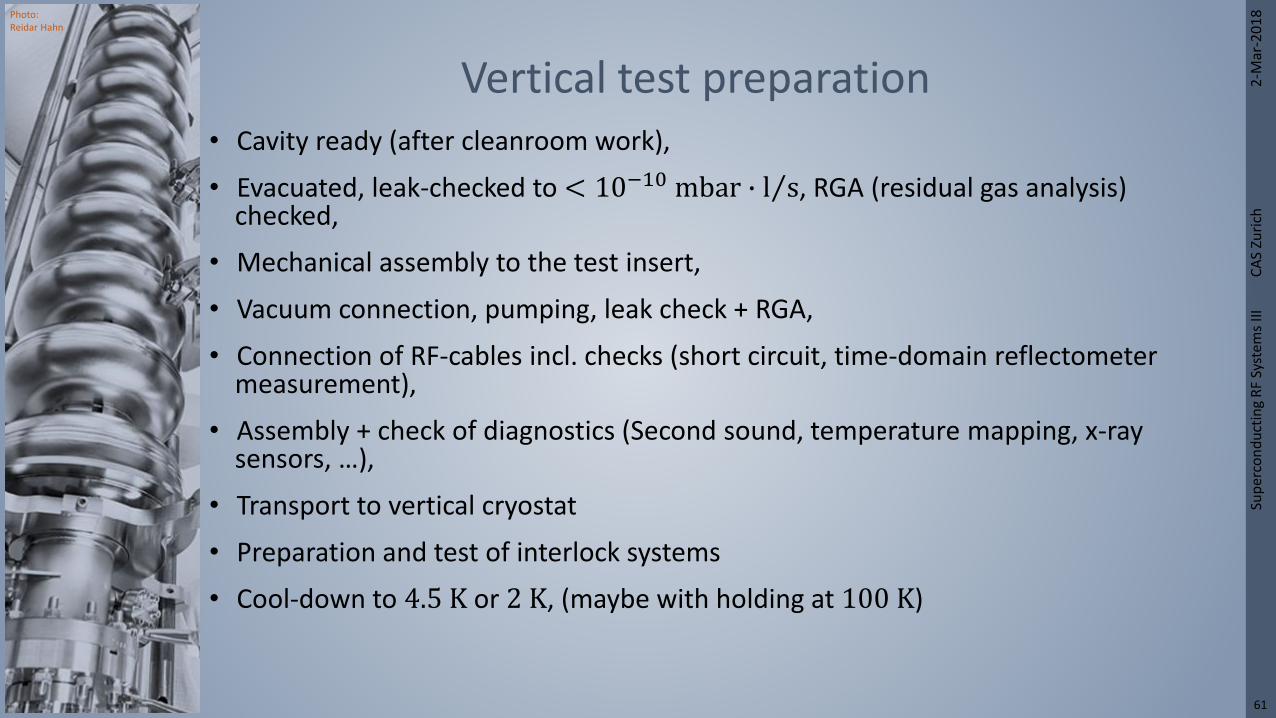
Photo: Reidar Hahn
2-M
ar-2
01
8Su
per
con
du
ctin
g R
F Sy
stem
s III
C
AS
Zuri
ch
61
• Cavity ready (after cleanroom work),
• Evacuated, leak-checked to < 10−10 mbar ∙ Τl s, RGA (residual gas analysis) checked,
• Mechanical assembly to the test insert,
• Vacuum connection, pumping, leak check + RGA,
• Connection of RF-cables incl. checks (short circuit, time-domain reflectometer measurement),
• Assembly + check of diagnostics (Second sound, temperature mapping, x-ray sensors, …),
• Transport to vertical cryostat
• Preparation and test of interlock systems
• Cool-down to 4.5 K or 2 K, (maybe with holding at 100 K)
Vertical test preparation

Photo: Reidar Hahn
2-M
ar-2
01
8Su
per
con
du
ctin
g R
F Sy
stem
s III
C
AS
Zuri
ch
62
Vertical test insert

Photo: Reidar Hahn
2-M
ar-2
01
8Su
per
con
du
ctin
g R
F Sy
stem
s III
C
AS
Zuri
ch
63
• Horizontal cavity tests are important in order to a cavity full equipped with its subsystems before a module integration• Power coupler
• Tuner
• Piezo-Tuners
• Check of cooling conditions + fluxtrapping
Horizontal Cavity Tests
Horizontal cryostat at DESY for high power pulsed operation (without beam)
Recommended