STUDY OF SPRAY BREAKUP AND MIXTURE IN A
GASOLINE DIRECT INJECTION ENGINE BY USING SIMULATION
MUZAMMIL BIN MOHAMAD ALIAS
Report submitted in partial fulfillment of the requirements
For the award of
Bachelor of Mechanical Engineering with Automotive Engineering
FACULTY OF MECHANICAL ENGINEERING
UNIVERSITY MALAYSIA PAHANG
JUNE 2013

vi
ABSTRACT
The project is to study the spray breakup and mixture in Gasoline Direct Injection
(GDI) The spray breakup and fuel air mixture in the injector system really important to
improve the fuel efficiency of Gasoline Direct Injection (GDI) Engine. Engine by using
simulation. By using the ANSYS Design Modeler, the design of the injector with
different inlet size and combustion chamber has been done. Then, by using
Computational Fluid Dynamic (CFD), ANSYS Fluent the flow simulation has been run.
The results extracted from the simulation are spray cone angle and penetration length.
The simulation is done based on different size of nozzle which are 0.2, 0.3, 0.4 and 0.5
mm. While for another variable is injection pressure which are 3, 6, 10, 15 and 20 Mpa.
From the result, the spray cone angle is decreasing as the pressure increase which means
the spray cone angle is inversely proportional to the injection pressure. While for
another results, the penetration length is directly proportional to the injection pressure.
The penetration length is increase as the injection pressure is increase. But, as the nozzle
diameter increase with the same pressure, the penetration length is decreases.

vii
ABSTRAK
Pemecahan semburan dan campuran udara dan minyak di dalam sistem suntikan adalah
penting untuk meningkatkan kadar efesiensi minyak enjin gasoline suntikan terus.
Projek ini dijalankan adalah untuk mengkaji pemecahan semburan dan campuran udara
dan minyak dalam enjin gasoline suntikan terus dengan menggunakan simulasi. Dengan
menggunakan perisian ‘ANSYS Design Modeler’, reka bentuk penyuntik dengan
berlainan saiz saluran masuk dan ruangan pembakaran telah dilukis. Kemudiannya,
dengan menggunakan perisian Computational Fluid Dynamic (CFD), ANSYS Fluent
simulasi arus akan dijalankan. Maklumat yang akan diambil setelah simulasi dijalankan
adalah sudut kon semburan dan panjang semburan.Simulasi dijalankan berdasarkan saiz
corong berlainan yaitu 02., 0.3, 0.4 dan 0.5 mm. Pembolehubah seterusnya adalah
tekanan suntikan dengan 3, 6, 10, 15 dan 20 Mpa tekanan digunakan. Keputusan yang
diperolehi daripada simulasi ini menunjukkan sudut semburan semakin mengecil
sekiranya tekanan penyuntik semakin meningkat.manakala bagi lagi satu keputusan
menunjukkan panjang semburan bergerak balas secara lansung dengan tekanan
penyuntik. Sekiranya tekanan punyuntik ditingkatkan nescaya panjang semburan juga
akan meningkat. Namun, apabila tekanan semburan dikekalkan, keputusan
menunjukkan semakin membesar saiz diameter corong penyembur, semakin pendek
jarak semburan.

viii
TABLE OF CONTENTS
Page
SUPERVISOR’S DECLARATION i
STUDENT’S DECLARATION ii
DEDICATION iii
ACKNOWLEDGEMENT iv
ABSTRACT v
ABSTRAK vi
TABLE OF CONTENTS viii
LIST OF TABLES x
LIST OF FIGURES xi
LIST OF ABBREVIATIONS xii
CHAPTER 1 INTRODUCTION
1.1 Introduction 1
1.2 Problem statement 2
1.3 Objective 2
1.4 Scopes of project 3
CHAPTER 2 LITERATURE REVIEW
2.1 Introduction 4
2.2 Literature review 4
CHAPTER 3 METHODOLOGY
3.1 Introduction 13
3.2 Flow chart 13
3.3 Design modeling 16
3.4 Meshing 17
3.5 Simulation 19
3.5.1 General setup 19

ix
3.5.2 Energy 19
3.5.3 Multiphase model 20
3.5.4 Viscous model 20
3.5.5 Species model 21
3.5.6 Discrete model phase 22
3.5.7 Injection parameter 22
3.5.8 Materials 23
3.5.9 Boundary conditions 23
3.5.10 Solution Method 24
3.5.11 Initialization and run calculation 25
3.5.12 Results 25
3.6 Data collection 26
CHAPTER 4 RESULT AND DISCUSSION
4.1 Introduction 28
4.2 Results and discussions 28
CHAPTER 5 CONCLUSION
5.1 Introduction 35
5.2 Conclusion 35
5.3 Recommendation 36
REFFERENCES 37
APPENDIX
A1 Gantt Chart for FYP 1 39
A2 Gantt Chart for FYP 2 40

x
LIST OF TABLES
Table No. Title Page
3.1 Nozzle and chamber dimension 17
3.2 Meshing setup 18
3.3 Multiphase model setup 20
3.4 Viscous model setup 20
3.5 Species model setup 21
3.6 Discrete phase model setup 22
3.7 Injection parameter setup 23
3.8 Fluid properties 23
3.9 Boundary conditions setup 24
3.10 Solution method setup 24
3.11 Run calculation setup 25
3.12 Results Setup 25
3.13 The symbol for collecting data 27
4.1 Results for 0.2 mm nozzle diameter 29
4.2 Results for 0.3 mm nozzle diameter 30
4.3 Results for 0.4 mm nozzle diameter 31
4.4 Results for 0.5 mm nozzle diameter 32
4.5 Results for penetration length 33
4.7 Results for spray angle 34

xi
LIST OF FIGURES
Figures No. Title Page
2.1 Type of injection. 5
2.2 The high pressure injectors. 7
2.3 An opened GDI Bosch injector. 7
2.4 The computational conditions. 8
2.5 The spray angle (θ0) and the hole-axis-angle (γ). 9
2.6 Examples of spray breakup in experimental result. 9
3.1 Flow chart for Semester 1 FYP progress 14
3.2 Flow chart for Semester 2 FYP progress 15
3.3 Modeling 16
3.4 Flow domain 17
3.5 Meshing 18
3.6 Energy setup 19
3.7 Example result 26
3.8 Data collection mefhod 26
4.1 Graph penetration length vs. injection pressure 33
4.2 Graph spray angle vs. injection pressure 34
A1 Gantt Chart for FYP 1 39
A2 Gantt Chart for FYP 2 40

xii
LIST OF ABBREVIATIONS
ICE Internal Combustion Engine
GDI Gasoline Direct Injection
PFI Port-fuel injection
ECU Engine Control Unit
3D Three dimension
2D Two dimension
SI Spark Ignition
DISI Direct Injection Spark Injection

CHAPTER 1
INTRODUCTION
1.1 INTRODUCTION
Internal combustion engine is an engine that widely use in automotive industry.
The ICE transforms the chemical energy which is the fuel into the useful mechanical
energy. These engine works almost in all automotive vehicles like car, motorcycle and
many more. Moreover, for the high power to weight ratios required transportation kind
of engine appear in the form gas turbine.
There are many type Internal Combustion Engines produce until today and each
of them have different kind of design. Each of them has their own strength and also the
weakness. As there have different kind of engine there must also have different kind of
fuel used to generate it. There are many kind of fuel that such as diesel, gasoline,
alcohol, natural gas and many more.
For most of the ICE will produce air pollution emissions. The chemical equation
for the complete combustion of fuel is CH4 + 2 O2 → CO2 + 2 H2O + energy. But, for
the some reason the complete combustion is almost impossible to achieve. The
incomplete combustion will produce the dangerous products such as nitrogen oxides
and sulfur. By increasing the amount of the air intake during the combustion will reduce
the emissions from the incomplete combustion.

2
Gasoline Direct Injection (GDI) is one of the Internal Combustion Engine
examples which use the fuel injection system to two and four stroke engines. The
advantages using this engine are increase the fuel efficiency and high power output. The
emissions level from the fuel combustion also can be controlled by the GDI system.
1.2 PROBLEM STATEMENT
Automotive industry nowadays realize that the decreasing of the fossil fuels will
continually and someday if there are no precaution step taken there could be even
worse. Gasoline, diesel and others will remain decreasing while the price will remain
increasing. Furthermore, the environmental issues had been serious lately while the
government and the NGO keep on campaigning about the important of the environment.
This make the automotive manufacturer and automotive company try to find the
alternative and better way of fueling. One of the main challenges for it is to make sure
an ignitable air fuel mixture at the spark plug for all kind of engine operating points for
the usage of different worldwide fuels (Sauer et al., 2008). Then, nowadays most of the
automotive engineers and company tend to move on and research more about the GDI
engine instead of other engine because of the better fuel consumption (Saito et al.,
2011). For the gasoline engine itself the manufacturer try to minimize the pollution and
increase the fuel consumption. And one of the solutions is to study about the spray
breakup and the mixture.
1.3 PROJECT OBJECTIVES
The main objectives for the project are:
1. To study the spray breakup for different parameter and geometry of the nozzle
injector with different pressure.
2. To develop 2- dimensional simulation model for Gasoline Direct Injection
engine.

3
1.4 SCOPE OF THE PROJECT
The scope of the project is to study the different type of injector for better air fuel
mixing in the Gasoline Direct Injection Engine. To conduct this analysis or simulation,
the software that can be used are ANSYS Fluent and Solidwork. First, the design of the
injector will be design by using Solidwork. The design then will be import into the
ANSYS Fluent for the spray breakup simulation. For the validity, the spray breakup
simulation results that had been done then will be compared to the previous research.

CHAPTER 2
LITERATURE REVIEW
2.1 INTRODUCTION
Jafarmadar and Heidarpoor, (2011) stated that for the past 20 years, the spark
ignition engines especially fuel system had been developed fluently from carburetion to
throttle body injection, then to simultaneous fire port fuel injection (PFI) and lately
phased sequential fire PFI Then, nowadays many automotive engineers tend to move on
and research more about the GDI engine instead of gasoline PFI engine because of the
better fuel consumption (Saito et al., 2011). Leipertz et al. (2010) stated that the mixture
formation appeared for modern engines are different compared to the gasoline since the
application of modern regenerative and synthetic fuels. It changes basically because the
evaporation behavior is affected by the boiling points of the fuels.
Furthermore for the SI engine, one of the most important processes is the spray
and mixture formation process. It is because, it will affect the whole combustion process
for the engine performance since the fuel will atomized and blend with the air to
provide the combustible mixture before the combustion take part(Celik et al., 2010).
The Direct Injection spark Ignition (DISI) engine categorized into three types as shown
in figure 2.1 according to their system which are Spray Guided, Wall Guided and Flow
Guided.
From the entire GDI engine concept, the spray guided technologies with charge
stratification will result the most possibility to reach the highest fuel efficiency.
Homogeneous mixture in the cylinder will happen when early injection at the inlet
stroke for full load operating points during the ignition time point (Park et al., 2009).

5
Figure 2.1: Type of injection
Zigan et al. (2010) investigated that for the partial load conditions, to increase
the fuel efficiency the charge stratification is more preferable. For the late injection
operating points, the pressurized fuel will be injected close to the spark plug where then
will be mix with the excess air to form the mixture. In case to ensure a stable ignition of
the air fuel mixture, it requires a very fast and reproducible fuel atomization and
evaporation.
Quick fuel atomization and evaporation is need for SI engine with a
reproducible placement of fuel vapor close to the spark plug to make sure a steady
ignition of the air fuel mixture. For the GDI engine, in order to avoid problems related
to the fuel film, the fuel is injected into the cylinder directly. Furthermore, GDI engine
need less fuel to start compare to the PFI engine. As the result it will reduce the HC
emission and also other harm gasses in the standard operating conditions (Abani et
al.2007)
Montanaro et al., (2011) stated that in theory the GDI engine, offers a lot of
opportunities for achieving important improvements in fuel consumption and emissions
reductions because it does not have any limitations. Moreover, the evaporating process
of the engine offer the air cooled by the fuel droplets hence allow the compression ratio
higher and lower the octane requirement for the fuels. In addition, the volumetric
efficiency also can be improvised if the injection occurs during the induction event.

6
In the GDI engine, the higher injection pressure and the shorter time for the
needle open is much needed in order to get the fuel spray atomization magnitude finer
(Rotondi and Bella, 2006). For the operating modes, there have three which is stratified
for the lean mixture, homogeneous for the lean mixture and homogeneous for
stoichiometric mixtures. The engine is operated with the stratified, homogeneous lean
and homogeneous stoichiometric modes; at low load and speed, at medium load and
speed and at high load and speed.
Som et al., (2008) stated that the design of the nozzle is the most importance
factor in a injection system since it resulting the turbulence flow that effect the spray
atomization. Instead of nozzle, the fuel property also is another criterion that should be
considering in this system. The fuel properties such as boiling point and volatility will
affect the droplet size and evaporation process inside the chamber. As example, the fuel
with high volatility will evaporate faster while the fuel with high boiling points will
remain in the droplet.
In the modern era, with the new type of synthetic fuels and regenerative fuels,
the study about the nozzle parameter and spray characteristic should be more advance as
the world needs to optimize the fuel usage. One of the main challenges for it is to make
sure an ignitable air fuel mixture at the spark plug for all kind of engine operating points
for the usage of different worldwide fuels (Sauer et al., 2008). Zigan et al., (2010) also
stated that large differences in microscopic spray behavior close to the nozzle were
detected at valve opening and closing conditions. The radial spray width at nozzle exit
as well as the microscopic cone angle decrease by trend with higher Reynolds- and
Weber numbers at early injection phases.
With the stable spray cone angle and a short penetration length also under
increase back pressure, the SG –DISI injector is the best reproducible spray created.
Although it comes with the best specification and advantages, it also has their own
weakness. The injector is very complex compare to the others and the price is also
expensive. Hence, the new technology with the less expensive multihole injectors is
created. In order to optimize the combustion concepts, optical measurement techniques
and spray modeling have become important tools (Iyer and Yi, 2009).
7
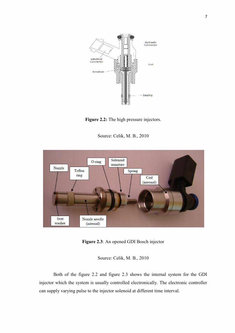
Figure 2.2: The high pressure injectors.
Source: Celik, M. B., 2010
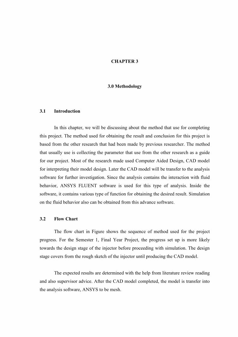
Figure 2.3: An opened GDI Bosch injector
Source: Celik, M. B., 2010
Both of the figure 2.2 and figure 2.3 shows the internal system for the GDI
injector which the system is usually controlled electronically. The electronic controller
can supply varying pulse to the injector solenoid at different time interval.

8
The figure 2.3 shows one of the computational conditions examples that is used
in flow simulation. The setup for each research computational study is different with the
others if the parameter that been used is different. Hemdal et al., (2011) stated that the
parameter that should be consider while doing the simulation or experiment are the
position of injector and spark plug, the combustion chamber geometry, piston geometry
and others. These parameters are important criteria for DI engine since the different size
or dimension will give the different results.
Figure 2.4: The computational conditions.
Source: Cao et al., (2008)
The efficiency of a DI engine depends on the mixture preparation and its
distribution inside the chamber. This phenomenon is based on the interaction of the in-
cylinder air motion, either tumble or swirl, and the spray characteristics from the high
pressure swirl injector which are generally employed for these engines (Chan et al.,
2012). With the high probability to improve the fuel consumption, coupled with the
advantages such as quick start that gives the transient response and the accurate control
of the air fuel mixture ratio make this engine worldwide interest as an automotive power
plant.

9
The effect of the gas phase on liquid phase is achieved by considering relative
terms and gradients for mass, momentum and energy. The transfer of thermal energy is
towards the droplet from the surrounding gas phase. With this gain in thermal energy,
the droplet temperature increases. At the droplet temperature, the fuel-vapor
concentration at the droplet surface is considered saturated.
Figure 2.5: The spray angle (θ) and the hole-axis-angle (γ)
Source: Cao et al., (2008)
Figure 2.6: Examples of spray breakup in experimental result.
Source: Cao et al., 2008

10
Computational Fluid Dynamics, CFD is a computer based tool for simulating the
behavior of systems involving fluid flow, heat transfer, and other related physical
processes. It works by solving the equations of fluid flow which in a special form over a
region of interest, with specified conditions on the boundary of that region.
There are various type of turbulence model existed for solving the computational
fluid problem, one of the common turbulence model is the K-Epsilon model. The
equation of the model as follows,
For turbulent kinetic energy, k,(⍴ ) + (⍴ ᵢ) = μ + μμ ᵢ + + − ⍴є − +For dissipation energy, ε epsilon,(⍴є) + (⍴є ) = μ + є є + є є ( + є ) − є⍴ є + SєThe turbulence viscosity is modeled as,μ = ⍴ μ ²єThe production of k is modeled as,= μ ²S is the modulus of the mean rate-of-strain tensor, defined as,≡ 2The model constant for k- ε₁є = 1.44 ₂є = 1.92 μ = 0.09 = 1.0 є = 1.3
The reason of listing the k-epsilon turbulence model is due the consideration of
the injector where the flow is in turbulent and compressible. The k-epsilon turbulence
model a model that usually use in ANSYS when the flow is related to turbulent and
compressible
(Eq. 1)
(Eq. 2)
(Eq. 3)
(Eq. 4)
(Eq. 5)
(Eq. 6)

11
The flow through the injector nozzle really related to the Bernoulli’s equation.
Bernoulli equation is concern about the conservation of kinetic, potential and flow
energies of the fluid stream. The equation considers the relationship between pressure,
velocity and elevation. Thus, the flow through the injection nozzle also is the same
situation. The fuel is supply from fuel tank to the injector with the high pressure at large
volume. When the injector ready to spray in the fuel inside the chamber, the injector
needle move up with the high speed created a space for the fuel to move through the
narrow space of nozzle then spay into the chamber. From the situation we can use the
equation where when the pressure is high, the velocity is low and when the pressure is
low, the velocity will be increase.
According to Millo et al.,(2011) stated that the analysis for spray atomization
and characteristic is important for the optimization for bore and stroke for the GDI
engine. As the engine is small, the fuel that needed for combustion process is also
reduce. In addition, as the engine is downsizing the emission that created from the
engine also will be decrease. Pollutant and soot emissions are closely influenced by the
parameter of the engine. That parameters are injector geometry (injector type),
combustion chamber design and operating engine conditions (pressure injection). There
have many benefits when the optimization of the engine is done.
Kiura et al., (2008) stated that there were many research that had been made
about the effect of the spray breakup and characteristic form the result it can conclude
that downsizing the nozzle hole diameter, increasing nozzle hole number and injection
pressure will lead to a better fuel atomization and spatial distribution, which will result
in a better engine performance and a lower emission level. The result will be different if
the parameter that had been use if different such as sometimes the short penetration tip
is suitable to avoid the wall impingement while in the other case sometimes the long
penetration tip is more suitable since it will give better air utilization. The vaporization
process of the spray is also very important because it will affect not only the ignition
stability, but also the flame propagation (Yamamoto et al., 2005)

12
According to Chan et al, (2012) among other technologies, such as a diesel
engine, turbocharging, and downsizing, the GDI engine was considered as one of the
technology paths for meeting future emission regulations for reducing greenhouse
gases. Furthermore, these engines have potential to achieve greater fuel economy
compared with a diesel engine at partial loads and give better performance than port fuel
injection (PFI) spark ignition engines at high loads(Moore et al. 2010). So, in order to
get the best efficiency for this GDI engine there must have serious investigation,
experimental, simulation and other way in order to successfully get it.
CHAPTER 3
3.0 Methodology
3.1 Introduction
In this chapter, we will be discussing about the method that use for completing
this project. The method used for obtaining the result and conclusion for this project is
based from the other research that had been made by previous researcher. The method
that usually use is collecting the parameter that use from the other research as a guide
for our project. Most of the research made used Computer Aided Design, CAD model
for interpreting their model design. Later the CAD model will be transfer to the analysis
software for further investigation. Since the analysis contains the interaction with fluid
behavior, ANSYS FLUENT software is used for this type of analysis. Inside the
software, it contains various type of function for obtaining the desired result. Simulation
on the fluid behavior also can be obtained from this advance software.
3.2 Flow Chart
The flow chart in Figure shows the sequence of method used for the project
progress. For the Semester 1, Final Year Project, the progress set up is more likely
towards the design stage of the injector before proceeding with simulation. The design
stage covers from the rough sketch of the injector until producing the CAD model.
The expected results are determined with the help from literature review reading
and also supervisor advice. After the CAD model completed, the model is transfer into
the analysis software, ANSYS to be mesh.

14
No
Yes
The meshing condition also is also according the idea form literature review
reading together with supervisor advice. If the model fail on for meshing process, means
there is an error occur on the CAD model and correction towards the injector model will
be done. On the same time also each main component that needed to be insert inside the
ANSYS later will be determine as expected parameters, boundary condition and type of
meshing.
Figure 3.1: Flow chart for Semester 1 FYP progress
Literature Review
Sketch injector
Design modeling by using CAD(injector and chamber)
Meshing
A
Start

15
No
Yes
For Figure 3.2 shows the Semester 2, Final Year Project, the progress is more
likely towards analysis stage. From the expected parameters, boundary condition and
also turbulence model, the most suitable component is chosen for the whole analysis
process. The analysis result will be taken for conclusion making. Final report writing
will finish for this final year project analysis and also final presentation.
Figure 3.2: Flow chart for Semester 2 FYP progress
ANSYS
Turbulent Flow Parameters Boundary condition
simulation
Report writing andpresentation
A
Finish

16
3.3 Design Modeling
Computational Fluid Dynamics or CFD is the analysis of systems involving
fluid flow, heat transfer and associated phenomena such as chemical reactions by means
of computer based simulations (Versteeg & Malasekera, 1995).
Computational Fluid Dynamics (CFD) itself emerged as a tool to cut cost and
time by doing away with costly experiments to produce better, more efficient
engineering designs. In practise, some experimental data or theoretical calculations will
still be needed to verify at least the unit or benchmark case, and possibly if time and
money permits the final design as well. Experimental data is also often needed for input
in CFD simulations, for example in setting the boundary conditions of the model.
Theoretical calculations based on simple models are always useful, providing back-of-
the-envelope estimates for boundary conditions and sometimes results expected. This
shows that an engineer will never do away with experiments and theoretical calculations
and totally depend on simulations (Anderson, 1995).
Since experimental results available are of gaseous jets issued from the Bosch
Gasoline Direct Injector into free space, a sufficiently large flow domain is required to
simulate this. A schematic of the flow domain for the benchmark case is shown in
Figure 3.3 and the setting shown in table 3.1.
Figure 3.3: Modeling
Recommended