Sprinkler Systems Installation GuideUser Guide for Geberit Mapress Pipework Installations to LPC Rules for Automatic Sprinkler Installations (incorporating BS EN 12845). Valid from 1. August 2011

1 Introduction 3
1.1 TheGeberitMapresspressfittingjoint 3
2 Components 4
2.1 GeberitMapresssystemcomponents 4 2.2 GeberitMapressStainlessSteel 4 2.2.1 GeberitMapressStainlessSteelpressfitings 4 2.2.2 GeberitMapressStainlessSteelsystempipes 4 2.3 GeberitMapressCarbonSteel 5 2.3.1 GeberitMapressCarbonSteelpressfittingsgalvanised 5 2.3.2 GeberitMapressCarbonSteelsystempipes 5 2.4 GeberitMapresspressingtools 5
3 Applicationsandplanningguidelines 6
3.1 InstallationinaccordancewithLPCB 6 3.2 Systemlayout 9 3.3 Hazardclassifications 9 3.4 Connectionstomainswater 9 3.5 Pipesupports 10 3.6 Calculationofpressurelossesinpipework 10 3.6.1 Equivalentpipelengths 11 3.7 Expansioncompensation 15 3.7.1 CalculatingexpansioninMapressStainlessSteel 16 3.7.2 CalculatingexpansioninMapressCarbonSteel 20 3.8 Layingtechniques 24 3.9 Wallpenetrations 24
4 Installation 25
4.1 Tooling 25 4.2 Transportandstorage 25 4.3 MakingaMapresspressconnection 25
4.4 Preparethepipeandfittingforthepressingoperation 26
5 Commissioning 30
5.1 Bendingthesystempipes 30 5.2 Connections 30 5.3 Flushingthepipes 30 5.4 Pressureandleaktest 30 5.5 Refillingandair-bleedingofthepipesystemforcommissioning 30 5.6 Compatibilityofadditives 30 5.7 Compatiblepaintsandcoatings 31 5.8 Maintenance 31 5.9 Servicelife 31
6 Supportservices 32
6.1 Geberittechnicalservice 32 6.2 Training 32U
serG
uideforG
eberitMapressPipew
orkInstallationstoLPCRules
forA
utom
aticSprinklerInstallations(incorporatingBSEN12845)
Contents
2
3
SprinklerSystemsInstallationGuideIntroduction
1IntroductionAutomaticsprinklersystemsaredesignedforthepurpose
ofdetectingandsuppressingorextinguishingafireas
earlyaspossibleduringitsinitialphasesothatitcanbe
safelyextinguishedusingothermeans.Thesesuppression
systemsandcomponentsaresubjecttospecial
requirementsbythecertifyingbodies.
LPCBapprovedGeberitMapresspipesandfittings
intendedforuseinsprinklersystemsinaccordancewiththe
LPCRulesforAutomaticSprinklerInstallationsareavailable
withanominaldiameterofDN20toDN100instainless
steelandcarbonsteel(internally&externallygalvanised).
WiththeGeberitMapresspressfittingpipeandfittings
system,pressingthefittingandpipetogetherproducesa
permanentandhigh-strengthpipejoint.Thepermanent
tightnessoftheconnectionisachievedbytheseal
ringsthatareinsertedintothepressfittingbeadbythe
manufacturer.Thesystemhasbeenusedsince1969
innon-alloysteelforclosedheatingsystemsandsince
1985instainlesssteelfordrinkingwatersystems.Since
thentheproductrangeofGeberitMapresspressfitting
productsforapplicationsintheareasofbuildingservices
andindustryaswellasinmarineapplicationshasbeen
continuouslyexpanded.GeberitMapresshasbeenwidely
usedinsprinklersystemsacrossEuropesince1984and
in2011hasreceivedLPCBapproval.
OtherGeberitMapressproductsoutsidetherange
approvedbyLPCBandintendedforuseintheLPCrules
forautomaticsprinklerinstallationscanbefoundinthe
GeberitSupplySystemsProductGuideandincludes
GeberitMapressCuNiFe,aseawaterresistantcopper-
nickelalloy.Forwaterextinguishingsystems,pipeswith
anominaldiameterofDN20toDN100areavailablein
stainlesssteel,carbonsteelinternally/externallygalvanised
andCuNiFe.
TheGeberitMapresspressfittingsystemismanufactured
tomeetthedesignandinstallationrequirementsof
buildingfireprotection.
Thesesystemsincludethefollowingcomponents:
•GeberitMapresspressfittings
•GeberitMapresssystempipes
•GeberitMapresspressingtools.
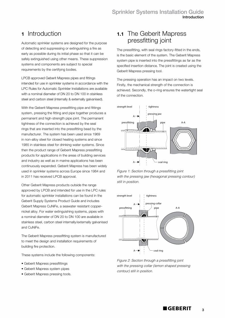
1.1 TheGeberitMapresspressfittingjoint
Thepressfitting,withsealringsfactory-fittedintheends,
isthebasicelementofthesystem.TheGeberitMapress
systempipeisinsertedintothepressfittingsasfarasthe
specifiedinsertiondistance.Thejointiscreatedusingthe
GeberitMapresspressingtool.
Thepressingoperationhasanimpactontwolevels.
Firstly,themechanicalstrengthoftheconnectionis
achieved.Secondly,theo-ringensuresthewatertightseal
oftheconnection.
Figure 1: Section through a pressfitting joint with the pressing jaw (hexagonal pressing contour) still in position.
Figure 2: Section through a pressfitting joint with the pressing collar (lemon shaped pressing contour) still in position.
seal ring
A
press�tting
pressing jaw
A
pipe A-A
tightness strength level
press�tting
pressing collar
tightnessstrength level
pipe A-A
seal ring
A
A
seal ring
A
press�tting
pressing jaw
A
pipe A-A
tightness strength level
press�tting
pressing collar
tightnessstrength level
pipe A-A
seal ring
A
A

SprinklerSystemsInstallationGuideComponents
2 Components
2.1 GeberitMapresssystem componentsTheindividualcomponentsoftheMapresssystemare
carefullymatched.Infireprotectionsystems,Geberit
Mapresspressfittingsmaythereforeonlybeusedin
conjunctionwithGeberitMapresssystempipesand
pressingtools.Sizes,weightsandpackageunitscanbe
foundintheGeberitproductcatalogue.
Thefittingendsareprovidedwithapressingindicatorin
thefactory.Thepressingindicatorisdestroyedbythe
pressingprocedureandshallsubsequentlybemanually
removedbytheinstallerafterpressing.
Thepressingindicatorhasthefollowingfunctions:
• Indicatestotheinstaller,beforethepressuretest,
thatthereareunpressedconnections
• Displaysthedimensionsofthefittingsinan
unpressedstate
• ClearlyidentifiesthefittingasaGeberitproductin
anunpressedstate
• Indicatesthematerialofthefittingbyitscolour-blue
forstainlesssteelandredforcarbonsteelinan
unpressedstate.
AllMapressfittingsalsocomewithaprotectionplugon
eachend.Thisprotectsthesealringfromdustanddirt,
increasinghygieneandsafety.
2.2 GeberitMapress StainlessSteelTheGeberitMapressStainlessSteelpressfittingsystem
isLPCBapprovedforuseinwetsprinklersystems
totheLPCRulesforAutomaticSprinklerInstallations.
Thesystemcanbeinstalleddirectlyinconcrete.
GeberitMapressStainlessSteelislistedundertheWater
RegulationsAdvisorySchemeforuseindrinkingwater
installations.CertificateNo:0610086.
2.2.1 GeberitMapressStainlessSteel
pressfittingsGeberitMapressStainlessSteelpressfittings,also
freeofsilicone,aremadeofhigh-alloyed316steel,
X5CrNiMo17-12-2inaccordancewithDINEN10088,
materialno.1.4401/AISI316.Allfittingsaresolutionand
brightannealedtoincreasecorrosionresistance.The
stainlesssteelpressconnectorsleakifunpressedandare
markedwiththemanufacturercodeaswellaswiththe
LPCBcertificationmarks(onthepackaginglabel).
2.2.2GeberitMapressStainless SteelsystempipesGeberitMapressStainlessSteelsystempipesare
madeofthesamehighquality316steelasthe
pressfittings.Afactorystandardensuresthatadditional
increasedrequirementsaremet:
• Increasedmolybdenumcontent,atleast2.2%
• Weldseamadditionallysmoothedontheinside,
solutionandbrightannealedforincreasedcorrosion
protection
• Pipelength6m
• Canbecoldbent(seesection5.1).
TheybeartheLPCB,FM,TUVandDVGWcertification
marks.Thethin-walledpipesandpressfittingslead
toaweightreductionofabout50%comparedto
conventionalstandardpipework.
Table1:Pipedimensionsinstainlesssteel
4
Ø=outsidediameter
s=wallthickness
Size(mm)
DN Øxs(mm) Weight(kg/m)
20 22.0x1.2 0.626
25 28.0x1.2 0.806
32 35.0x1.2 1.260
40 42.0x1.5 1.523
50 54.0x1.5 1.974
65 76.1x2.0 3.715
80 89.9x2.0 4.357
100 108.0x2.0 5.315

SprinklerSystemsInstallationGuideComponents
2.3 GeberitMapress CarbonSteelTheGeberitMapresspressfittingsystemmadeofcarbon
steel,isLPCBapprovedforuseinwetsprinklersystems
totheLPCRulesforAutomaticSprinklerInstallations.
2.3.1 GeberitMapressCarbon Steelpressfittings, galvanisedTheGeberitMapressCarbonSteelpressfittingsaremade
ofnon-alloysteel,materialno.1.0034,inaccordancewith
DINEN10305.Theyaregalvanicallyzinc-platedwitha
protectivelayer(Fe/Zn8B,bluechromated)thatisatleast
8μmthick.Furthermore,GeberitMapressCarbonSteel
pressfittingsleakifunpressedandaremarkedwithared
pressingindicator.Theybearthemanufacturercodeas
wellastheLPCB,VdSandFMCertificationmarks(onthe
packaginglabel).
2.3.2 GeberitMapressCarbonSteelsystempipesinternally/externally
galvanisedTheGeberitMapresssystempipemadeofnon-alloysteel,
materialno.1.0215,isathin-walled,weldedand
internally/externallygalvanisedprecisionsteelpipethat
alsomeetstherequirementsoftheGeberitMapress
factorystandardconcerningdimensionalaccuracyand
surfacequality.Thesepipesaremanufacturedfrommetal
stripsgalvanisedonbothsides.
Thethicknessofthezinclayerontheinternalaswellas
theexternalsurfaceis15–27μm[zinc275g/m2].
Theappliedzincplatingprocessproducesasmooth,
high-densityzinclayer,freeofmicroscopicgapsand
cavitiesforevenbetteranti-corrosionproperties.
Theweldingseamontheoutsideofthepipeis
subsequentlygalvanised.Thepipesaremarked,among
otherthings,withthemanufacturercodeaswellas
withtheLPCB,FMandVdSCertificationmarks(onthe
packaginglabel).Thethin-walledpipesandpressfittings
leadtoaweightreductionofabout50%comparedto
conventionalstandardpipework.
Table2:Pipedimensionsinnon-alloysteel,internally/externallygalvanised
2.4 GeberitMapress pressingtoolsDependingonthediameterandworkingpressureofthe
installation,theGeberitMapresspipejointsaremade
usingdifferentGeberitMapresspressingtools(seetable3
formoredetails).
Ø=outsidediameter
s=wallthickness
5
Size(mm)
DN Øxs(mm) Weight(kg/m)
20 22.0x1.2 0.758
25 28.0x1.2 0.980
32 35.0x1.2 1.239
40 42.0x1.5 1.498
50 54.0x1.5 1.942
65 76.1x2.0 3.655
80 89.9x2.0 4.286
100 108.0x2.0 5.228

SprinklerSystemsInstallationGuideApplicationsandplanningguidelines
GeberitMapressCarbonSteelpressfittingswiththe
standardblackbutylrubbersealring(CIIR)inconjunction
withtheinternally/externallygalvanisedsystempipeare
LPCBapprovedforuseinaccordancewiththeLPCRules
forAutomaticSprinklerInstallationsinwetsystemswith
pressures12to16bar,dependingonthedimensionsand
pressfittingtoolused(seeTable3).ForafulllistofLPCB
approvedGeberitproducts,pleasereferto
www.redbooklive.comorseeTables4-5.
Table3:InstallationinaccordancewithLPCBapproval
6
Table4:LPCBapprovedGeberitMapressStainlessSteelSprinklerPipeworkSystemComponents
Description Size/mm
Pipe 22,28,35,42,54,76.1,88.9,108
Coupling 22,28,35,42,54,76.1,88.9,108
SlipCoupling 22,28,35,42,54,76.1,88.9,108
Bend90° 22,28,35,42,54,76.1,88.9,108
Bend90°withplainend 22,28,35,42,54,76.1,88.9,108
Bend45° 22,28,35,42,54,76.1,88.9,108
Bend45°withplainend 22,28,35,42,54,76.1,88.9,108
Reducerwithplainend 28x22,35x22,35x28,42x28,42x35,
54x35,54x42,76.1x54,88.9x54
88.9x76.1,108x76.1,108x88.9
T-pieceequal 22,28,35,42,54,76.1,88.9,108
3 Applicationsand planningguidelinesTheseinstallationinstructionsapplytoGeberitMapress
pressfittingsystemsmadeofstainlesssteelandnon-alloy
steelgalvanisedinaccordancewithLPCRulesforAutomatic
SprinklerInstallationsincorporatingBSEN12845.
FordetailsregardingtheinstallationofGeberitMapressfor
sprinklersystemsinaccordancetoVdSandFMapproval,
pleasecontactGeberitdirectly.
Toassistyouwiththeplanning,youcandownloadCAD
dataforthepressfittingsindxfordwgformatfromthe
ServicesectionoftheGeberithomepage.
3.1 Installationinaccordance withLPCBGeberitMapressStainlessSteelpressfittingsandsystem
pipesareLPCBapprovedforuseinaccordancewiththe
LPCRulesforAutomaticSprinklerInstallations.
Theapprovalcoverswetsystemsatoperatingpressures
uptoeither12or16bar,dependingonthedimensions
andpressfittingtoolused(seeTable3)inconjunctionwith
theblackbutylrubbersealring(CIIR).
WorkingPressure(bar)
1216
Ø(mm)
Tool HCPS ECO301 HCPS ECO301
22 XY XY
28 XY XY
35* XY XY
42 XY XY
54 XY XY
76.1 XY XY X
88.9 XY XY X
108 XY
X=stainlesssteelY=carbonsteel
*35mmpressingcollartobeusedarticleno:90538
SprinklerSystemsInstallationGuideApplicationsandplanningguidelines
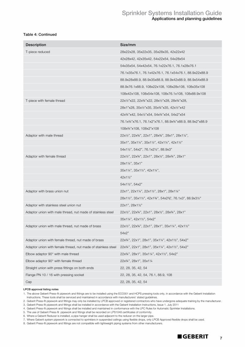
Table4:Continued
LPCBapprovallistingnotes
1.TheaboveGeberitPress-fitpipeworkandfittingsaretobeinstalledusingtheECO301andHCPSpressingtoolsonly,inaccordancewiththeGeberitInstallationInstructions.Thesetoolsshallbeservicedandmaintainedinaccordancewithmanufacturers’statedguidelines.
2. GeberitPress-fitpipeworkandfittingsmayonlybeinstalledbyLPCBapprovedorregisteredcontractorswhohaveundergoneadequatetrainingbythemanufacturer.3. GeberitPress-fitpipeworkandfittingsshallbeinstalledinaccordancewiththeGeberitInstallationInstructions,Issue1.July20114. GeberitPress-fitpipeworkandfittingsshallbeinstalledandmaintainedinconformancewiththeLPCRulesforAutomaticSprinklerInstallations.5. TheuseofGeberitPress-fitpipeworkandfittingsshallberecordedonLPS1048certificatesofconformity.6.WhereaGeberitReducerisinstalled,apipehangershallbeusedadjacenttothereduceronthelargerpipe.7.WhereGeberitsystempipeworkisconnectedtosprinklersinsuspendedceilingsusingflexibledrops,onlyLPCBApprovedflexibledropsshallbeused.8. GeberitPress-fitpipeworkandfittingsarenotcompatiblewithlightweightpipingsystemsfromothermanufacturers.
7
Description Size/mm
T-piecereduced 28x22x28,35x22x35,35x28x35,42x22x42
42x28x42,42x35x42,54x22x54,54x28x54
54x35x54,54x42x54,76.1x22x76.1,76.1x28x76.1
76.1x35x76.1,76.1x42x76.1,76.1x54x76.1,88.9x22x88.9
88.9x28x88.9,88.9x35x88.9,88.9x42x88.9,88.9x54x88.9
88.9x76.1x88.9,108x22x108,108x28x108,108x35x108
108x42x108,108x54x108,108x76.1x108,108x88.9x108
T-piecewithfemalethread 22x½”x22,22x¾”x22,28x½”x28,28x¾”x28,
28x1”x28,35x½”x35,35x¾”x35,42x½”x42
42x¾”x42,54x½”x54,54x¾”x54,54x2”x54
76.1x¾”x76.1,76.1x2”x76.1,88.9x¾”x88.9,88.9x2”x88.9
108x¾”x108,108x2”x108
Adaptorwithmalethread 22x½”,22x¾”,22x1”,28x¾”,28x1”,28x1¼”,
35x1”,35x1¼”,35x1½”,42x1¼”,42x1½”
54x1½”,54x2”,76.1x2½”,88.9x3”
Adaptorwithfemalethread 22x½”,22x¾”,22x1”,28x½”,28x¾”,28x1”
28x1¼”,35x1”
35x1¼”,35x1½”,42x1¼”,
42x1½”
54x1½”,54x2”
Adaptorwithbrassunionnut 22x1”,22x1¼”,22x1½”,28x1”,28x1¼”
28x1½”,35x1½”,42x1¾”,54x2³/8”,76.1x3”,88.9x3½”
Adaptorwithstainlesssteelunionnut 22x1”,28x1½”
Adaptorunionwithmalethread,nutmadeofstainlesssteel 22x½”,22x¾”,22x1”,28x½”,28x¾”,28x1”
35x1¼”,42x1½”,54x2”
Adaptorunionwithmalethread,nutmadeofbrass 22x½”,22x¾”,22x1”,28x1”,35x1¼”,42x1½”
54x2”
Adaptorunionwithfemalethread,nutmadeofbrass 22x¾”,22x1”,28x1”,35x1¼”,42x1½”,54x2”
Adaptorunionwithfemalethread,nutmadeofstainlesssteel 22x¾”,22x1”,28x1”,35x1¼”,42x1½”,54x2”
Elbowadaptor90°withmalethread 22x¾”,28x1”,35x1¼”,42x1½”,54x2”
Elbowadaptor90°withfemalethread 22x¾”,28x1”,35x1¼
Straightunionwithpressfittingsonbothends 22,28,35,42,54
FlangePN10/16withpressingsocket 22,28,35,42,54,76.1,88.9,108
Cap 22,28,35,42,54

Table5:LPCBapprovedGeberitMapressCarbonSteelinternally/externallygalvanised
SprinklerPipeworkSystemComponents
SprinklerSystemsInstallationGuideApplicationsandplanningguidelines
8
Description Size/mm
Pipe 22,28,35,42,54,76.1,88.9,108
Coupling 22,28,35,42,54,76.1,88.9,108
SlipCoupling 22,28,35,42,54,76.1,88.9,108
Bend90° 22,28,35,42,54,76.1,88.9,108
Bend90°withplainend 22,28,35,42,54,76.1,88.9,108
Bend45° 22,28,35,42,54,76.1,88.9,108
Bend45°withplainend 22,28,35,42,54,76.1,88.9,108
Reducerwithplainend 28x22,35x22,35x28,42x28,42x35,
54x35,54x42,76.1x54,88.9x54
88.9x76.1,108x76.1,108x88.9
T-pieceequal 22,28,35,42,54,76.1,88.9,108
T-piecereduced 28x22x28,35x22x35,35x28x35,42x22x42
42x28x42,42x35x42,54x22x54,54x28x54
54x35x54,54x42x54,76.1x22x76.1,76.1x28x76.1
76.1x35x76.1,76.1x42x76.1,76.1x54x76.1,88.9x22x88.9
88.9x28x88.9,88.9x35x88.9,88.9x42x88.9,88.9x54x88.9
88.9x76.1x88.9,108x22x108,108x28x108,108x35x108
108x42x108,108x54x108,108x76.1x108,108x88.9x108
T-piecewithfemalethread 22x½”x22,22x¾”x22,28x½”x28,28x¾”x28,
28x1”x28,35x½”x35,35x¾”x35,42x½”x42
42x¾”x42,54x½”x54,54x¾”x54,54x2”x54
76.1x¾”x76.1,76.1x2”x76.1,88.9x¾”x88.9,88.9x2”x88.9
108x¾”x108,108x2”x108
Adaptorwithmalethread 22x½”,22x¾”,22x1”,28x¾”,28x1”,28x1¼”,
35x1”,35x1¼”,35x1½”,42x1¼”,42x1½”
54x1½”,54x2”,76.1x2½”,88.9x3”
Adaptorwithfemalethread 22x¾”,28x½”,28x1”
Adaptorwithplainandweldingend 15,18,22,28,35,42,54
Adaptorforgroovesystems 54
Adaptorwithbrassunionnut 22x1”,22x1¼”,22x1½”,28x1”,28x1¼”
28x1½”,35x1½”,35x2”,42x1¾”,42x2”,42x2¼”,
42x2³/8”,42x2½”,54x2½”,54x2¾”
Adaptorunionwithmalethread 22x¾”,28x1”,35x1¼”,42x1½”
54x2”
Adaptorunionwithfemalethread,nutmadeofstainlesssteel 22x¾”,22x1”,28x1”,35x1¼”,42x1½”,54x2”
Elbowadaptor90°withmalethread 22x¾”
Elbowadaptor90°withfemalethread 28x½”
Bendadaptor90°withfemalethread 22x¾”,28x½”

SprinklerSystemsInstallationGuideApplicationsandplanningguidelines
LPCBapprovallistingnotes1. TheaboveGeberitPress-fitpipeworkandfittingsaretobeinstalledusingtheECO301andHCPSpressingtoolsonly,inaccordancewiththeGeberitInstallation
Instructions.Thesetoolsshallbeservicedandmaintainedinaccordancewithmanufacturers’statedguidelines.
2. GeberitPress-fitpipeworkandfittingsmayonlybeinstalledbyLPCBapprovedorregisteredcontractorswhohaveundergoneadequatetrainingbythemanufacturer.3. GeberitPress-fitpipeworkandfittingsshallbeinstalledinaccordancewiththeGeberitInstallationInstructions,Issue1.August 20114. GeberitPress-fitpipeworkandfittingsshallbeinstalledandmaintainedinconformancewiththeLPCRulesforAutomaticSprinklerInstallations.5. TheuseofGeberitPress-fitpipeworkandfittingsshallberecordedonLPS1048certificatesofconformity.6. WhereaGeberitReducerisinstalled,apipehangershallbeusedadjacenttothereduceronthelargerpipe.7. WhereGeberitsystempipeworkisconnectedtosprinklersinsuspendedceilingsusingflexibledrops,onlyLPCBApprovedflexibledropsshallbeused.8. GeberitPress-fitpipeworkandfittingsarenotcompatiblewithlightweightpipingsystemsfromothermanufacturers.
9
Table5:
Continued
Description Size/mm
Straightunionwithpressfittingsonbothends 22,28,35,42,54
FlangePN10/16withpressingsocket 76.1,88.9,108
Cap 22,28,35,42,54
3.2 SystemlayoutGeberitMapressissuitableforuseineachelementofan
automaticsprinklersystem.SeeFigure3.
3.3 HazardclassificationsGeberitMapressisapprovedforuseinhazard
classificationuptoandincludingOH3asdefinedin
LPCrulesforautomaticsprinklerinstallationsandin
accordancewiththeLPCBapproval.
3.4 Connectionstomainswater
GeberitMapressStainlessSteelholdsWRASapproval
andthereforecanbeconnectedtowatersupply.
GeberitMapressCarbonSteelisnotWRASapproved.
Whenusingnon-WRASapprovedcomponentsinsystems
connectedtotownmainwatersupplies,WRASapproved
backflowpreventersmustbeused.
81
2
3
9
57
6
4
Key
1 Sprinklerhead
2 Riser
3 Distributionpipespur
4 Armpipe
5 Maindistributionpipe
6 Controlvalveset
7 Riser
8 Rangepipes
9 Drop
Figure 3: main elements of a sprinkler system
SprinklerSystemsInstallationGuideApplicationsandplanningguidelines
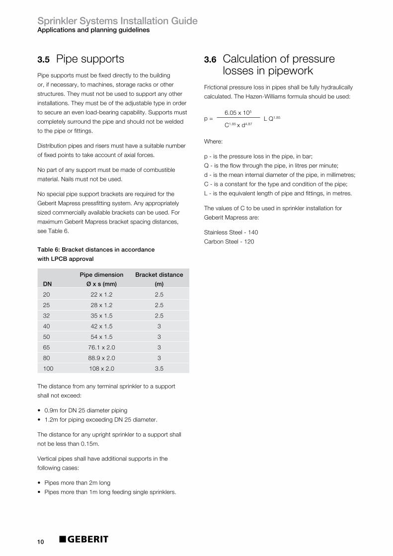
3.5 PipesupportsPipesupportsmustbefixeddirectlytothebuilding
or,ifnecessary,tomachines,storageracksorother
structures.Theymustnotbeusedtosupportanyother
installations.Theymustbeoftheadjustabletypeinorder
tosecureanevenload-bearingcapability.Supportsmust
completelysurroundthepipeandshouldnotbewelded
tothepipeorfittings.
Distributionpipesandrisersmusthaveasuitablenumber
offixedpointstotakeaccountofaxialforces.
Nopartofanysupportmustbemadeofcombustible
material.Nailsmustnotbeused.
Nospecialpipesupportbracketsarerequiredforthe
GeberitMapresspressfittingsystem.Anyappropriately
sizedcommerciallyavailablebracketscanbeused.For
maximumGeberitMapressbracketspacingdistances,
seeTable6.
Table6:Bracketdistancesinaccordance
withLPCBapproval
3.6 Calculationofpressurelossesinpipework
Frictionalpressurelossinpipesshallbefullyhydraulically
calculated.TheHazen-Williamsformulashouldbeused:
Where:
p-isthepressurelossinthepipe,inbar;
Q-istheflowthroughthepipe,inlitresperminute;
d-isthemeaninternaldiameterofthepipe,inmillimetres;
C-isaconstantforthetypeandconditionofthepipe;
L-istheequivalentlengthofpipeandfittings,inmetres.
ThevaluesofCtobeusedinsprinklerinstallationfor
GeberitMapressare:
StainlessSteel-140
CarbonSteel-120
Thedistancefromanyterminalsprinklertoasupport
shallnotexceed:
• 0.9mforDN25diameterpiping
• 1.2mforpipingexceedingDN25diameter.
Thedistanceforanyuprightsprinklertoasupportshall
notbelessthan0.15m.
Verticalpipesshallhaveadditionalsupportsinthe
followingcases:
• Pipesmorethan2mlong
• Pipesmorethan1mlongfeedingsinglesprinklers.
10
p=6.05x10⁵
C1.85xd4.87LQ1.85
Pipedimension Bracketdistance
DN Øxs(mm) (m)
20 22x1.2 2.5
25 28x1.2 2.5
32 35x1.5 2.5
40 42x1.5 3
50 54x1.5 3
65 76.1x2.0 3
80 88.9x2.0 3
100 108x2.0 3.5

SprinklerSystemsInstallationGuideApplicationsandplanningguidelines
3.6.1 Equivalentpipelengths
11
Table7:Equivalentpipelength–MapressØ12-22mm
(continuedoverleaf)
Designation DimensionsØxs(mm) 12x1.0 15x1.0 18x1.0 22x1.0
Bend90° 0.7 0.267 0.370 0.479 0.630
Elbowadaptor90° 1.5 0.572 0.793 1.026 1.351
Pipebridge 0.5 0.191 0.264 0.342 0.450
Bend45° 0.5 0.191 0.264 0.342 0.450
Reducer 0.2 — 0.106 0.137 0.180
Sleeve/Adaptor 0.1 0.038 0.053 0.068 0.090
T-piece(flowseparation) 1.3 0.496 0.688 0.889 1.171
T-piece(flowintegration) 0.9 0.343 0.476 0.616 0.811
T-piece(through-flow) 0.3 0.114 0.159 0.205 0.270
V
V
V
V
V
V
V
V
V
V
V
V
V
V
V
V
V
V
V
V
V
V
V
V
V
V
V
V
V
V
V
V
V
V
V
V
V
V
V
V
V
V
V
V
V
V
V
V
V
V
V
V
V
V
V
V
V
V
V
V
V
V
V
V
V
V
V
V
V
V
V
V
V
V
V
V
V
V
V
V
V
V
V
V
V
V
V
V
V
V
Pressfitting LossCoefficient

SprinklerSystemsInstallationGuideApplicationsandplanningguidelines
12
Table7:Continued
Designation DimensionsØxs(mm) 12x1.0 15x1.0 18x1.0 22x1.0
T-piece(through-flow 0.2 0.076 0.106 0.137 0.180forflowseparation)
T-piece(counterflow 3.0 1.145 1.587 2.052 2.702forflowintegration)
T-piece(counterflow 1.5 0.572 0.793 1.026 1.351forflowseparation)
Cross-piece30° 0.2 — — 0.137 0.180(through-flow)
Pipecross30° 1.3 — — 0.889 1.171(flowseparation)
Pipecross30° 0.9 — — 0.616 0.811(flowintegration)
Pipecross90° 0.2 — 0.106 0.137 0.180(through-flow)
Pipecross90° 1.7 — 0.899 1.163 1.531(flowseparation)
Pipecross90° 1.3 — 0.688 0.889 1.171(flowintegration)
V
V
V
V
V
V
V
V
V
V
V
V
V
V
V
V
V
V
V
V
V
V
V
V
V
V
V
V
V
V
V
V
V
V
V
V
V
V
V
V
V
V
V
V
V
V
V
V
V
V
V
V
V
V
V
V
V
V
V
V
V
V
V
V
V
V
V
V
V
V
V
V
V
V
V
V
V
V
V
V
V
V
V
V
V
V
V
V
V
V
Pressfitting LossCoefficient

SprinklerSystemsInstallationGuideApplicationsandplanningguidelines
13
Table8:Equivalentpipelength–MapressØ28-54mm
Designation DimensionsØxs(mm) 28x1.5 35x1.5 42x1.5 54x1.5
Bend90° 0.7 0.829 1.121 1.427 1.975
Elbowadaptor90° 1.5 1.777 2.403 3.057 4.232
Pipebridge 0.5 0.592 — — —
Bend45° 0.5 0.592 0.801 1.019 1.411
Reducer 0.2 0.237 0.320 0.408 0.564
Sleeve/Adaptor 0.1 0.118 0.160 0.204 0.282
T-piece 1.3 1.540 2.082 2.649 3.668(flowseparation)
T-piece 0.9 1.066 1.442 1.834 2.539(flowintegration)
T-piece(through-flow 0.3 0.355 0.481 0.611 0.846forflowintegration)
T-piece(through-flow 0.2 0.237 0.320 0.408 0.564forflowseparation)
T-piece(counterflow 3.0 3.553 4.805 6.114 8.465forflowintegration)
T-piece(counterflow 1.5 1.777 2.403 3.057 4.232forflowseparation)
LossCoefficient
54
V
V
V
V
V
V
54
V
V
V
V
V
V
54
V
V
V
V
V
V
54
V
V
V
V
V
V
54
V
V
V
V
V
V
54
V
V
V
V
V
V
54
V
V
V
V
V
V
54
V
V
V
V
V
V
54
V
V
V
V
V
V
54
V
V
V
V
V
V
54
V
V
V
V
V
V
54
V
V
V
V
V
V
Pressfitting
SprinklerSystemsInstallationGuideApplicationsandplanningguidelines
14
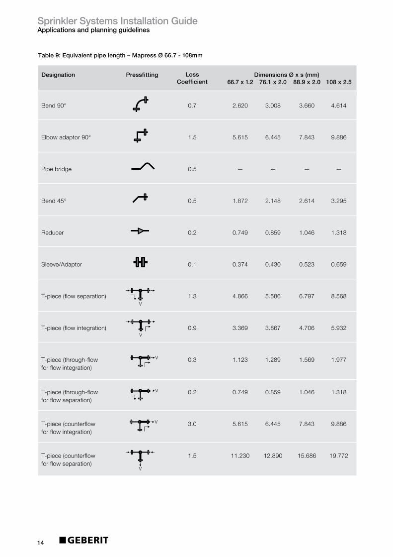
Table9:Equivalentpipelength–MapressØ66.7-108mm
Designation DimensionsØxs(mm) 66.7x1.2 76.1x2.0 88.9x2.0 108x2.5
Bend90° 0.7 2.620 3.008 3.660 4.614
Elbowadaptor90° 1.5 5.615 6.445 7.843 9.886
Pipebridge 0.5 — — — —
Bend45° 0.5 1.872 2.148 2.614 3.295
Reducer 0.2 0.749 0.859 1.046 1.318
Sleeve/Adaptor 0.1 0.374 0.430 0.523 0.659
T-piece(flowseparation) 1.3 4.866 5.586 6.797 8.568
T-piece(flowintegration) 0.9 3.369 3.867 4.706 5.932
T-piece(through-flow 0.3 1.123 1.289 1.569 1.977forflowintegration)
T-piece(through-flow 0.2 0.749 0.859 1.046 1.318forflowseparation)
T-piece(counterflow 3.0 5.615 6.445 7.843 9.886forflowintegration)
T-piece(counterflow 1.5 11.230 12.890 15.686 19.772forflowseparation)
LossCoefficient
Pressfitting
54
V
V
V
V
V
V
54
V
V
V
V
V
V
54
V
V
V
V
V
V
54
V
V
V
V
V
V
54
V
V
V
V
V
V
54
V
V
V
V
V
V
54
V
V
V
V
V
V
54
V
V
V
V
V
V
54
V
V
V
V
V
V
54
V
V
V
V
V
V
54
V
V
V
V
V
V
54
V
V
V
V
V
V

SprinklerSystemsInstallationGuideApplicationsandplanningguidelines
15
3.7 ExpansioncompensationPipesexpanddifferentlyduetothermaleffects
dependingontheproductmaterial.Thisshouldbe
consideredwhen:
• Creatingexpansionspace
• Installingexpansioncompensations
• Positioningfixedpointsandslidingpoints
Thebendingandtorsionalstressoccurringduring
theoperationofapipearereliablyabsorbed,takingthe
expansioncompensationintoaccount.
Thefollowingaffecttheexpansioncompensation:
• Material
• Buildingconditions
• Operatingconditions.
Slightchangesinthelengthofpipescanbe
accommodatedbytheelasticityofthepipenetwork.
Expansioncompensatorsusedare:
• Pipeleg
• Ubend.
Thefollowingshowtheprincipleassemblyofthepipeleg
andUbend.
Figure 4: Expansion compensation by pipe leg
BS: Bendingleg
F: Fixedpoint
GL: Slidingpoint
L: Pipelength
L1BS2
GLGLF GL
GL
F
L2
BS1
Figure 5: Expansion compensation by U bends
BS: Bendingleg
F: Fixedpoint
L: Pipelength
L1 L2
BSF F
SprinklerSystemsInstallationGuideApplicationsandplanningguidelines
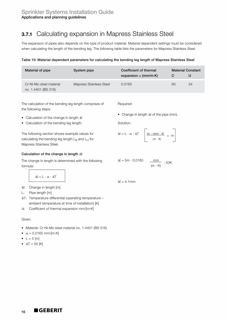
16
Materialofpipe Systempipe Coefficientofthermal MaterialConstant
expansionα(mm/m.K) C U
Cr-Ni-Mosteelmaterial MapressStainlessSteel 0.0165 60 34
no.1.4401(BS316)
Table10:MaterialdependentparametersforcalculatingthebendingleglengthofMapressStainlessSteel
3.7.1 CalculatingexpansioninMapressStainlessSteelTheexpansionofpipesalsodependsonthetypeofproductmaterial.Materialdependentsettingsmustbeconsidered
whencalculatingthelengthofthebendingleg.ThefollowingtableliststheparametersforMapressStainlessSteel.
Required:
• ChangeinlengthΔlofthepipe(mm).
Solution:
Δl=L·α·ΔTm·mm·K=m m·K
Δl=5m·0.0165mm·50K
(m·K)
Δl=4.1mm
Thecalculationofthebendingleglengthcomprisesof
thefollowingsteps:
• CalculationofthechangeinlengthΔl
• Calculationofthebendingleglength.
Thefollowingsectionshowsexamplevaluesfor
calculatingthebendingleglengthLBandLUfor
MapressStainlessSteel.
CalculationofthechangeinlengthΔl
Thechangeinlengthisdeterminedwiththefollowing
formula:
Δl=L·α·ΔT
Δl: Changeinlength[m]
L: Pipelength[m]
ΔT: Temperaturedifferential(operatingtemperature–
ambienttemperatureattimeofinstallation)[K]
Α: Coefficientofthermalexpansionmm/[m·K]
Given:
• Material:Cr-Ni-Mosteelmaterialno.1.4401(BS316)
• α=0.0165mm/[m·K]
• L=5[m]
• ΔT=50[K]

SprinklerSystemsInstallationGuideApplicationsandplanningguidelines
17
Calculationofthebendingleglength:StainlessSteel
Thecalculationofthebendingleglengthdependsonthe
typeofbendingleg:
• Expansioncompensationthroughpipeleg/forbranch
pipe:CalculationofthebendingleglengthLB• ExpansioncompensationbyUbends:Calculationof
thebendingleglengthLU
CalculationofthebendingleglengthLB
ThebendingleglengthLWtobecalculatedisdefinedas
followswithexpansioncompensationthroughpipelegs
andforbranchpipes:
Figure 6: Expansion compensation by pipe leg
F: Fixedpoint
GL: Slidingpoint
LB: Lengthofthebendingleg
Figure 7: Expansion compensation for branching pipe
F: Fixedpoint
GL: Slidingpoint
LB: Lengthofthebendingleg
Table11:ChangeinlengthΔl(mm)forMapressStainlessSteelsystempipe
∆I
LB
GL
F
F GL
GL
∆I
∆I
LB
GL
GL
PipelengthTemperaturedifferentialΔT(K)
10 20 30 40 50 60 70 80 90 100
1 0.17 0.33 0.50 0.66 0.83 0.99 1.16 1.32 1.49 1.65
2 0.33 0.66 0.99 1.32 1.65 1.98 2.31 2.64 2.97 3.30
3 0.50 0.99 1.49 1.98 2.48 2.97 3.47 3.96 4.46 4.95
4 0.66 1.32 1.98 2.64 3.30 3.96 4.62 5.28 5.94 6.60
5 0.83 1.65 2.48 3.30 4.13 4.95 5.78 6.60 7.43 8.25
6 0.99 1.98 2.97 3.96 4.95 5.94 6.93 7.92 8.91 9.90
7 1.16 2.31 3.47 4.62 5.78 6.93 8.09 9.24 10.40 11.55
8 1.32 2.64 3.96 5.28 6.60 7.92 9.24 10.56 11.88 13.20
9 1.49 2.97 4.46 5.94 7.43 8.91 10.40 11.88 13.37 14.85
10 1.65 3.30 4.95 6.60 8.25 9.90 11.55 13.20 14.85 16.50
L(m)
SprinklerSystemsInstallationGuideApplicationsandplanningguidelines
18
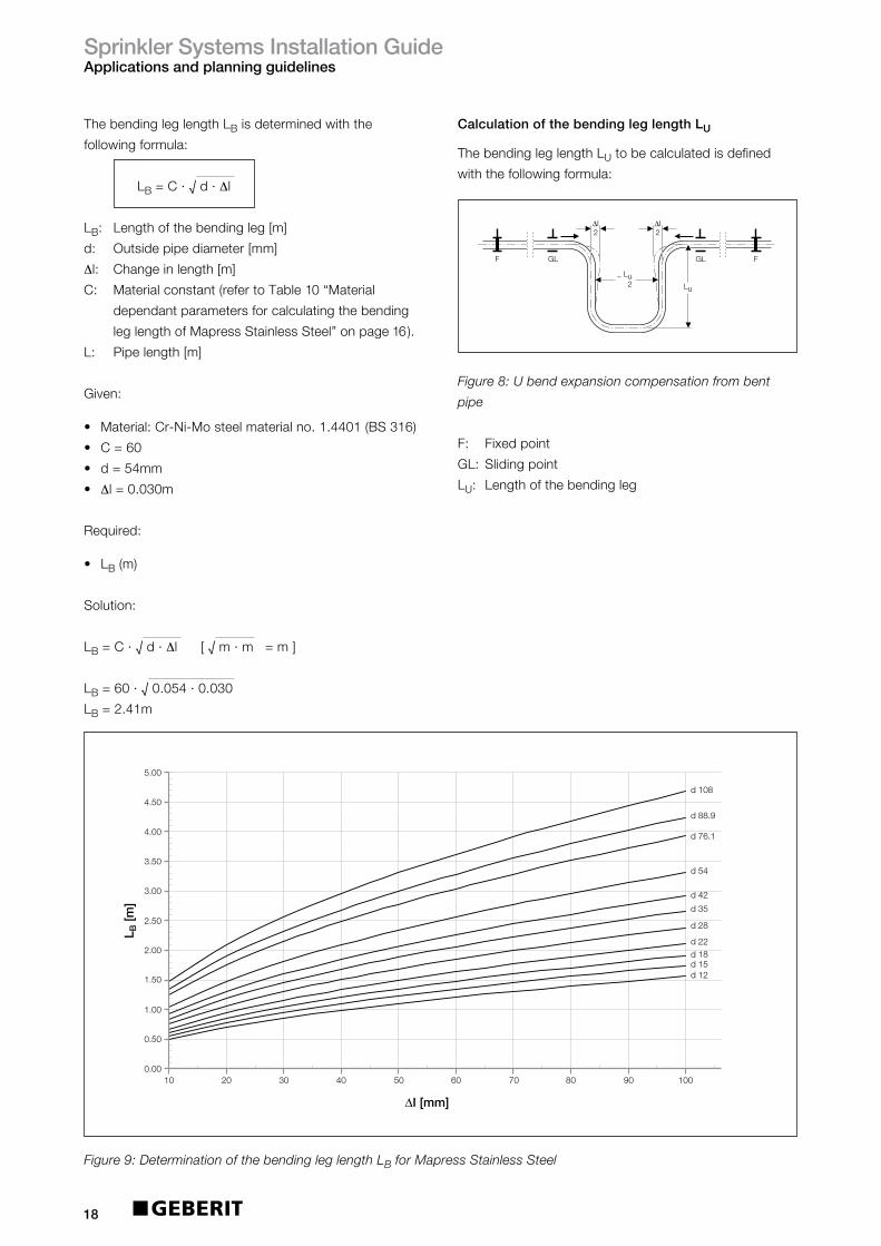
ThebendingleglengthLBisdeterminedwiththe
followingformula:
LB=C·√d·Δl
LB: Lengthofthebendingleg[m]
d: Outsidepipediameter[mm]
Δl: Changeinlength[m]
C: Materialconstant(refertoTable10“Material
dependantparametersforcalculatingthebending
leglengthofMapressStainlessSteel”onpage16).
L: Pipelength[m]
Given:
• Material:Cr-Ni-Mosteelmaterialno.1.4401(BS316)
• C=60
• d=54mm
• Δl=0.030m
Required:
• LB(m)
Solution:
LB=C·√d·Δl[√m·m=m]
LB=60·√0.054·0.030
LB=2.41m
CalculationofthebendingleglengthLU
ThebendingleglengthLUtobecalculatedisdefined
withthefollowingformula:
Figure 8: U bend expansion compensation from bent
pipe
F: Fixedpoint
GL: Slidingpoint
LU: Lengthofthebendingleg
d 22
d 42
d 54
d 76.1
d 88.9
d 108
d 15d 12
d 18
d 28
d 35
0.00
0.50
1.00
1.50
2.00
2.50
3.00
3.50
4.00
4.50
5.00
L B [m
]
20 40 60 80 10010 30 50 70 90
∆I [mm]
Figure 9: Determination of the bending leg length LB for Mapress Stainless Steel
∆I 2
Lu
GL GL
∆I 2
~ Lu 2
F F
SprinklerSystemsInstallationGuideApplicationsandplanningguidelines
19
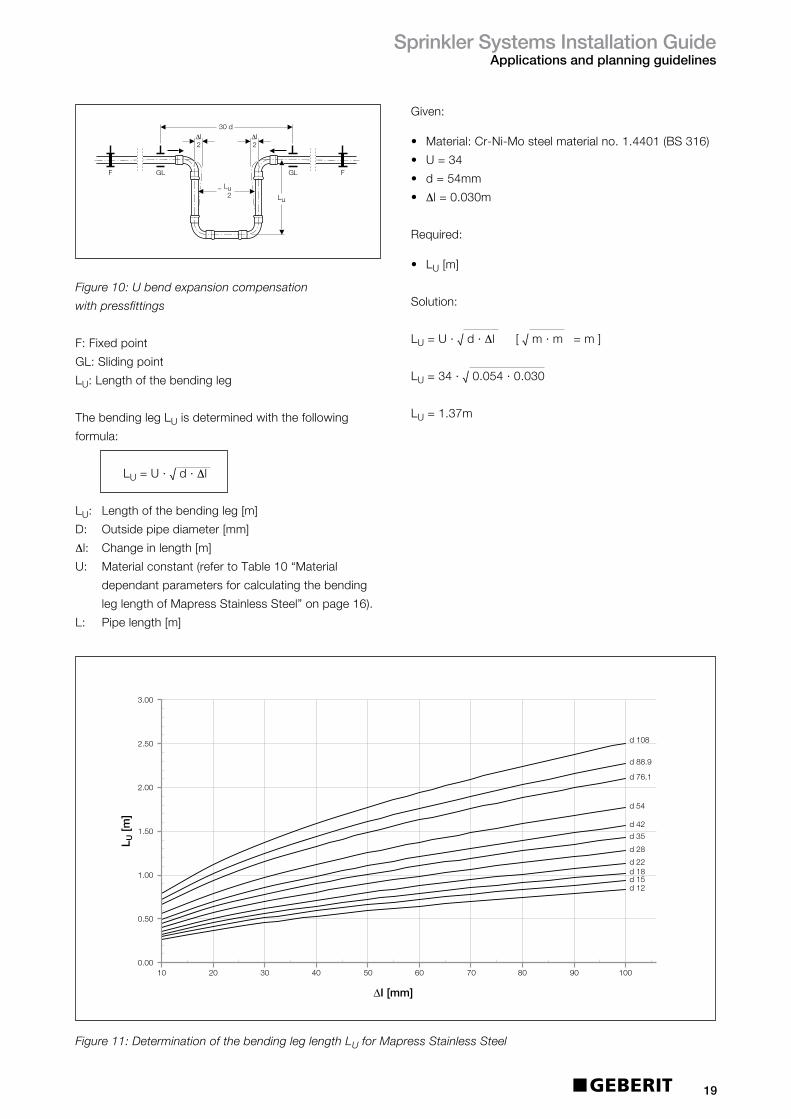
Figure 10: U bend expansion compensation
with pressfittings
F:Fixedpoint
GL:Slidingpoint
LU:Lengthofthebendingleg
ThebendinglegLUisdeterminedwiththefollowing
formula:
LU=U·√d·Δl
LU: Lengthofthebendingleg[m]
D: Outsidepipediameter[mm]
Δl: Changeinlength[m]
U: Materialconstant(refertoTable10“Material
dependantparametersforcalculatingthebending
leglengthofMapressStainlessSteel”onpage16).
L: Pipelength[m]
~ Lu 2
∆I2
Lu
∆I2
30 d
GL GLF F
d 12
d 22
d 42
d 54
d 76.1
d 88.9
d 108
d 15d 18
d 28
d 35
0.00
0.50
1.00
1.50
2.00
2.50
L U [m
]
20 40 60 80 10010 30 50 70 90
∆I [mm]
3 00.
Figure 11: Determination of the bending leg length LU for Mapress Stainless Steel
Given:
• Material:Cr-Ni-Mosteelmaterialno.1.4401(BS316)
• U=34
• d=54mm
• Δl=0.030m
Required:
• LU[m]
Solution:
LU=U·√d·Δl[√m·m=m]
LU=34·√0.054·0.030
LU=1.37m

SprinklerSystemsInstallationGuideApplicationsandplanningguidelines
20
3.7.2 CalculatingexpansioninMapressCarbonSteel
Solution:
Δl=L·α·ΔTm·mm·K=m
m·K
Δl=35m·0.012mm·50K
(m·K)
Δl=21mm
Table12:MaterialdependentparametersforcalculatingthebendingleglengthofMapressCarbonSteel
Theexpansionofpipesalsodepends,amongstothers,onthetypeofproductmaterial.Materialdependent
parametersmustbeconsideredwhencalculatingthelengthofthebendingleg.Thefollowingtableliststheparameters
forMapressCarbonSteel.
Thecalculationofthebendingleglengthcomprisesof
thefollowingsteps:
• CalculationofthechangeinlengthΔl
• CalculationofthebendingleglengthLB
Thefollowingsectionshowsexamplevaluesfor
calculatingthebendingleglengthLWandLUfor
MapressCarbonSteel.
CalculationofthechangeinlengthΔl
Thechangeinlengthisdeterminedwiththefollowing
formula:
Δl=L·α·ΔT
Δl: Changeinlength[m]
L: Pipelength[m]
ΔT: Temperaturedifferential(operatingtemperature–
ambienttemperatureattimeofinstallation)[K]
α: Coefficientofthermalexpansionmm/[m·K]
Given:
• Material:Non-alloysteelmaterialno.1.0034
• α=0.0120m/[m·K]
• L=35[m]
• ΔT=50[K]
Required:
• ChangeinlengthΔlofthepipe[mm]
Materialofpipe Systempipe Coefficientofthermal MaterialConstant
expansionα(mm/m.K) C U
Non-alloysteel, MapressCarbonSteel 0.012 4525
materialno.1.0215

SprinklerSystemsInstallationGuideApplicationsandplanningguidelines
21
Calculationofthebendingleglength:CarbonSteel
Thecalculationofthebendingleglengthdependsonthe
typeofbendingleg:
• Expansioncompensationthroughpipeleg/forbranch
pipe:CalculationofthebendingleglengthLB• ExpansioncompensationbyUbends:Calculationof
thebendingleglengthLU
CalculationofthebendingleglengthLB
ThebendingleglengthLBtobecalculatedisdefinedas
followswithexpansioncompensationthroughpipelegs
andforbranchpipes:
Figure12:Expansioncompensationbypipeleg
F: Fixedpoint
GL: Slidingpoint
LB: Lengthofthebendingleg
Figure13:Expansioncompensationforbranchingpipe
F: Fixedpoint
GL: Slidingpoint
LB: Lengthofthebendingleg
PipelengthTemperaturedifferentialΔT(K)
10 20 30 40 50 60 70 80 90 100
1 0.12 0.24 0.36 0.48 0.60 0.72 0.84 0.96 1.08 1.20
2 0.24 0.48 0.72 0.96 1.20 1.44 1.68 1.92 2.16 2.40
3 0.36 0.72 1.08 1.44 1.80 2.16 2.52 2.88 3.24 3.60
4 0.48 0.96 1.44 1.92 2.40 2.88 3.36 3.84 4.32 4.80
5 0.60 1.20 1.80 2.40 3.00 3.60 4.20 4.80 5.40 6.00
6 0.72 1.44 2.16 2.88 3.60 4.32 5.04 5.76 6.48 7.20
7 0.84 1.68 2.52 3.36 4.20 5.04 5.88 6.72 7.56 8.40
8 0.96 1.92 2.88 3.84 4.80 5.76 6.72 7.68 8.64 9.60
9 1.08 2.16 3.24 4.32 5.40 6.48 7.56 8.64 9.72 10.80
10 1.20 2.40 3.60 4.80 6.00 7.20 8.40 9.60 10.80 12.00
Table13:ChangeinlengthΔl(mm)forMapressCarbonSteelsystempipe
∆I
LB
GL
F
F GL
GL
∆I
∆I
LB
GL
GL
L(m)

SprinklerSystemsInstallationGuideApplicationsandplanningguidelines
22
ThebendingleglengthLBisdeterminedwiththe
followingformula:
LB=C·√d·Δl
LB: Lengthofthebendingleg[m]
d: Outsidepipediameter[mm]
Δl: Changeinlength[m]
C: Materialconstant(refertoTable12“Material
dependentparametersforcalculatingthebending
leglengthofMapressCarbonSteel”onpage20).
L: Pipelength[m]
Given:
• Material:Non-alloysteelmaterialno.1.0034
• C=45
• d=54[mm]
• Δl=0.021[m]
Required:
• LB[m]
Solution:
LB=C·√d·Δl[√m·m=m]
LB=45·√0.054·0.021
LB=1.52m
CalculationofthebendingleglengthLU
ThebendingleglengthLUtobecalculatedisdefined
withthefollowingformula:
Figure 14: U bend expansion compensation
from bent pipe
F: Fixedpoint
GL: Slidingpoint
LU: Lengthofthebendingleg
20 40 60 80 10010 30 50 70 90
∆I [mm]
d 12
d 22
d 42
d 54
d 76.1
d 88.9
d 108
d 15d 18
d 28
d 35
L B [m
]
0.00
0.50
1.00
1.50
2.00
2.50
3.00
3.50
4.00
4.50
5.00
Figure 15: Determination of the bending leg length LB for Mapress Carbon Steel
∆I 2
Lu
GL GL
∆I 2
~ Lu 2
F F

SprinklerSystemsInstallationGuideApplicationsandplanningguidelines
23
Figure 16: U bend expansion compensation with
pressfittings
F: Fixedpoint
GL: Slidingpoint
LU: Lengthofthebendingleg
ThebendinglegLUisdeterminedwiththefollowing
formula:
LU=U·√d·Δl
LU: Lengthofthebendingleg(m)
D: Outsidepipediameter(mm)
Δl: Changeinlength(m)
U: Materialconstant(refertoTable12“Material
dependantparametersforcalculatingthebending
leglengthofMapressCarbonSteel”onpage20).
L: Pipelength(m)
~ Lu 2
∆I2
Lu
∆I2
30 d
GL GLF F
d 12
d 22
d 42
d 54
d 76.1
d 88.9
d 108
d 15d 18
d 28
d 35
0.00
0.50
1.00
1.50
2.00
2.50
L U [m
]
20 40 60 80 10010 30 50 70 90
∆I [mm]
3 00.
Figure 17: Determination of the bending leg length LU for Mapress Carbon Steel
Given:
• Material:Non-alloysteelmaterialno.1.0034
• U=25
• d=54mm
• Δl=0.021m
Required:
• LU(m)
Solution:
LU=U·√d·Δl[√m·m=m]
LU=34·√0.054·0.021
LU=0.84m
SprinklerSystemsInstallationGuideApplicationsandplanningguidelines
24
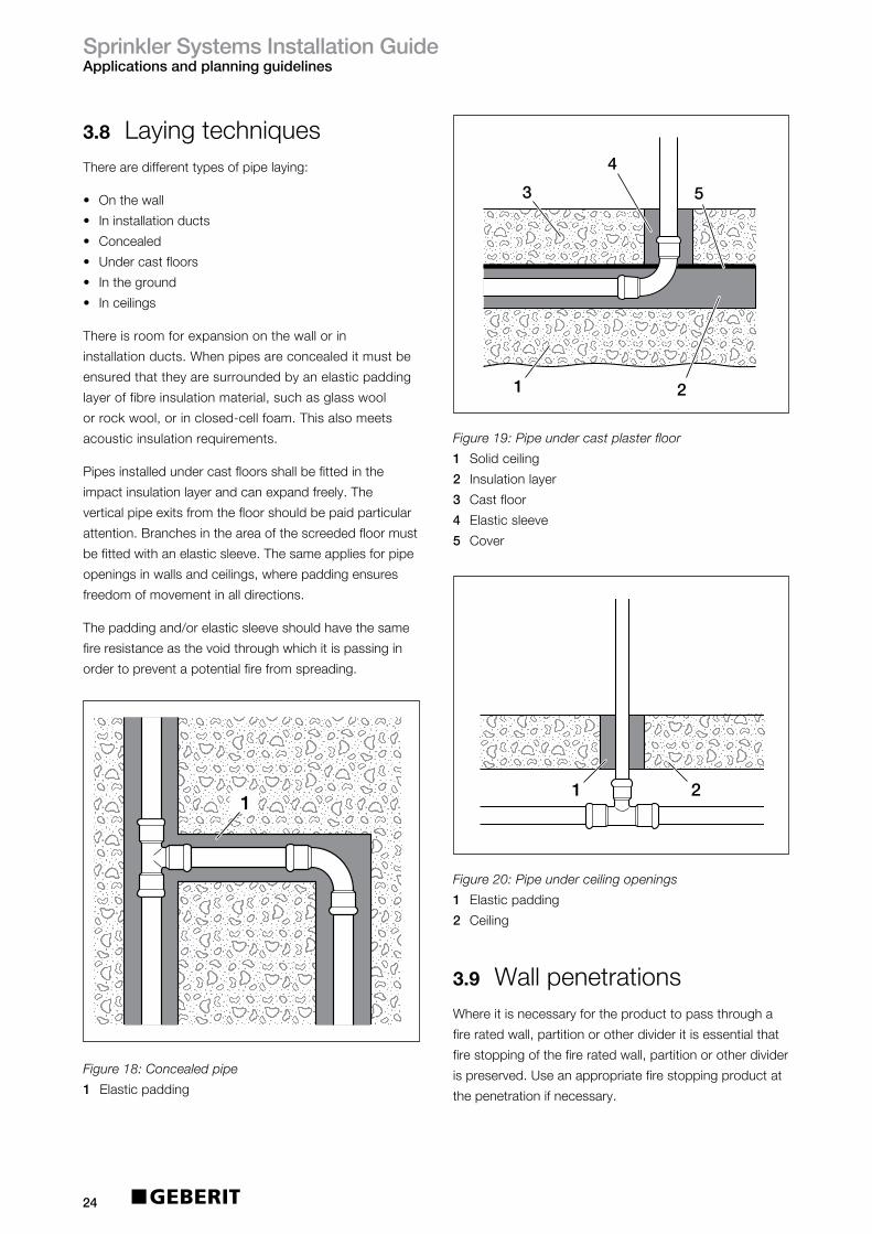
3.8 LayingtechniquesTherearedifferenttypesofpipelaying:
• Onthewall
• Ininstallationducts
• Concealed
• Undercastfloors
• Intheground
• Inceilings
Thereisroomforexpansiononthewallorin
installationducts.Whenpipesareconcealeditmustbe
ensuredthattheyaresurroundedbyanelasticpadding
layeroffibreinsulationmaterial,suchasglasswool
orrockwool,orinclosed-cellfoam.Thisalsomeets
acousticinsulationrequirements.
Pipesinstalledundercastfloorsshallbefittedinthe
impactinsulationlayerandcanexpandfreely.The
verticalpipeexitsfromthefloorshouldbepaidparticular
attention.Branchesintheareaofthescreededfloormust
befittedwithanelasticsleeve.Thesameappliesforpipe
openingsinwallsandceilings,wherepaddingensures
freedomofmovementinalldirections.
Thepaddingand/orelasticsleeveshouldhavethesame
fireresistanceasthevoidthroughwhichitispassingin
ordertopreventapotentialfirefromspreading.
3.9 WallpenetrationsWhereitisnecessaryfortheproducttopassthrougha
fireratedwall,partitionorotherdivideritisessentialthat
firestoppingofthefireratedwall,partitionorotherdivider
ispreserved.Useanappropriatefirestoppingproductat
thepenetrationifnecessary.
1
Figure 18: Concealed pipe
1 Elasticpadding
Figure 19: Pipe under cast plaster floor
1 Solidceiling
2 Insulationlayer
3 Castfloor
4 Elasticsleeve
5 Cover
Figure 20: Pipe under ceiling openings
1 Elasticpadding
2 Ceiling
4
3 5
21
21
21

SprinklerSystemsInstallationGuideInstallation
25
4 Installation
4.1 ToolingThefollowingtoolingcombinationsshouldbeusedforinstallingGeberitMapressforfireprotectionsystems.
4.2 TransportandstorageDonotallowGeberitMapresssystempipesand
pressfittingstogetdirtyordamagedintransitorstorage.
Pipesneedtobestoredinsideinadrylocation.
4.3 MakingaMapress pressconnectionAMapresspressconnectionismadeasfollows:
• Preparethepipeandfittingforthepressingoperation.
• Pushpipeintofittingtocorrectinsertiondepth.
• Optional:WithØ54-108mmfitthemounting
deviceMH1.
• Pressthefitting.
WARNING
Riskofcorrosion
Keepcuttingtoolsanddeburringtoolsfree
fromCarbonSteelchipswhencuttingMapress
StainlessSteel
Donotusehigh-speedcuttingwheelstocut
thepipeorfittingstolength
Onlyusecuttingtoolsthataresuitablefor
workingwithsteel
Leakingpressconnectioncanbecausedby
damagedsealring
Deburrtheoutsideandinsideofthepipeends
completely
Donottiltthepipeintothepressfitting.
Pushthepressfittingontothepipe,turningthe
pipeslightly
Onlyuselubricantswhicharefreefromoil
andgrease
Onlyshortenthefittingswithplainendsupto
themaximumpermissibleshorteningdimensionk,
indicatedintheproductguide.
i
DiametersPressed
22-88.9mm
35/42/54mm=
(ZB302)90668
76.1/88.9mm=
(ZB321)90674
3
3
3
76-108mmHCPS
HCPS
ECO301
ECO301
ECO301
115V/50Hz
230V/50Hz
125v/60Hz
CEE17yellow
BS1363Aplug
MarineNEMAplug
691.312.1P.3
691.310.P5.3
691.312.2P.3
90644(22mm)
90645(28mm)
230V/50Hz
115V/50Hz
BS1363Aplug
CEE17yellow
691.420.P5.1
691.422.1P.1HCPS n/a n/a
35mm=90538
42mm=90539
54mm=90540
76.1mm-=90671
88.9mm=90672
Model Voltage Plugtype ArticleNo.Jawstype
compatability
PressingJaw
(Sizemm)Adaptor
PressingCollar
(Sizemm)
Table14:SuitabletoolingcombinationsforGeberitMapressandFireProtectionsystems
76.1mm=90570
88.9mm=90571
108mm=90572
SprinklerSystemsInstallationGuideInstallation
26
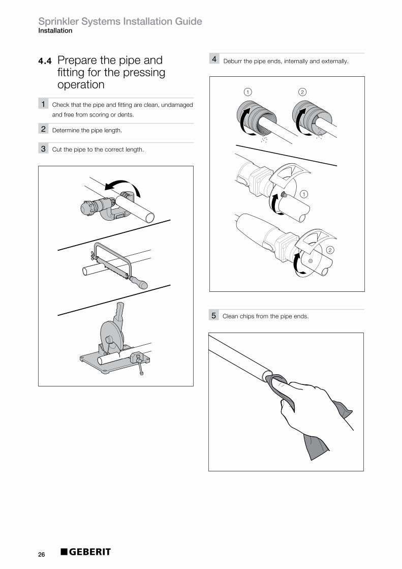
4.4 Preparethepipeand fittingforthepressing operation
1
2
Checkthatthepipeandfittingareclean,undamaged
andfreefromscoringordents.
Determinethepipelength.
3 Cutthepipetothecorrectlength.
1 2
1
2
4 Deburrthepipeends,internallyandexternally.
5 Cleanchipsfromthepipeends.

SprinklerSystemsInstallationGuideInstallation
27
di
E
6a Marktheinsertiondistance.
Insufficientmechanicalstrengthifcorrect
insertion(E)isnotobserved.i
distance
6b Onfittingswithaplainend,marktheinsertion
distanceontheend.
1
2
7 Removetheplugfromthefitting.
di
8 Checkthesealring.

SprinklerSystemsInstallationGuideInstallation
28
E
E
CAUTION
Leakingconnectionduetostress
corrosioncracking.Donotuse
Teflonforsealing
Maketheconnectionwiththethreadedfitting
9 Pushthefittingontothepipeuptothemarked
insertiondistance.
10 Alignthepipe.
Fixthepipeinposition.
Sealinthethreadedconnection.
Insertthethreadedfittingandscrewintoplace,
counterholdingthethreadedfitting.
123
Thefittingcanbepushedinmoreeasilyifoil
andgrease-freelubricantisappliedorthefitting
isimmersedinwaterorsoapywater.
iTheinstallationdimensionsaregiveninthe
operatinginstructionsofthemountingaid.i
Optional:withØ54-108mmfitthemountingaidMH1
• Clampthepipeswiththejawsofthemountingaid.
Pressthefitting
Prerequisites
• Thepipeorpre-assembledelementsarealigned
• Threadedjointsmustbesealedin.
Ensurethatthediameterofthepressfittingmatches
thediameterofthepressingjaworpressingcollar:
Ø12-35mmusepressingjaw,Ø42-108mmuse
pressingcollarandadaptor.
Pressthefitting.
1
2

SprinklerSystemsInstallationGuideInstallation
29
Result
•Themarkoftheinsertiondistanceisvisible.

SprinklerSystemsInstallationGuideCommissioning
30
5 Commissioning
5.1 BendingthesystempipesGeberitMapresssystempipescanbecoldbent.Todo
so,usecommerciallyavailablebendingtools(manually,
hydraulicallyorelectricallyoperated).Itisimportantto
alwaysusethebendingsegmentsfortheparticularouter
diameterofthesystempipes.Thebendingradiusand
thesuitabilityofthebendingtoolisdeterminedbythe
manufacturerofthetool.GeberitMapressrecommends
usingabendingradiusofr=3.5xOD.
5.2 Connections• ConnectingtosprinklerheadsandISO65pipework
InordertoconnectGeberitMapresstoalternative
pipingsystems,accessoriesandsprinklerheads,
threadedadaptorsareavailableundertheLPCBlisting
ofapprovedproducts.
• Threadedjoints
GeberitMapresscomponentscanbecombinedwith
threadedfittingsorsystempipesmadeofnon-ferrous
metal.WhenGeberitMapressStainlessSteeladaptors
areused,onlychloride-freesealantsmaybeemployed.
• Flangeconnections
GeberitMapresscomponentscanbeconnectedto
DINflanges[PN10/16]withflangedadaptors(see
GeberitSupplySystemsProductGuide)
5.3 FlushingthepipesAllmetallicpipingsystemsareatahighriskofcorrosion
whentheyarepartiallyfilled.Werecommendthatthe
pipeisflushedthoroughlypriortocommissioningusing
drinkingwater.
Ifthepipecannotbecompletelydrainedbefore
commissioningandifthepipecannotbeblowndrywith
airafterflushing,thepipemustbeflushedwithfully
desalinatedwater.
5.4 PressureandleaktestAllinstallationpipeworkshallbehydostaticallytestedfor
nolessthan2hours,toapressureofnolessthan15bar,
or1.5timesthemaximumpressuretowhichthesystem
willbesubjected,(bothmeasuredattheinstallation
controlvalves),whicheveristhegreater.
Aninitialtestwithaircanbeperformedifthereistobea
gapbetweenthetestingandcommissioningphase.
Forsafetyreasons,thepressureforthistestshouldnever
exceed3bar.Asecondtestwithwatershouldalwaysbe
carriedoutimmediatelypriortocommissioning.
5.5 Refillingandair-bleeding ofthepipesystemfor commissioningIfthepipesystemwasdrainedcompletelyafter
pressuretesting,thewater-carryingpipesmustbe
thoroughlyair-bledbeforecommissioningandthen
remaincompletelyfull.Thewaterusedtofillthepipes
mustcomplywiththedrinkingwaterdirective2001,
withregardtoitschloridecontent.
5.6 CompatibilityofadditivesWateradditivesaremainlyusedforprovidinganti-freeze
propertiesforwetsprinklersystemsduringthewinter
season.Commonlyusedaremixturesbasedon
anti-freezeagents(ethylene-orpropyleneglycol)in
combinationwithcorrosioninhibitors.Theglycolswill
alwayshaveaninfluenceonthezinclayerontheinsideof
thepipingsystemandcanthereforenotberecommended
foruseinconjunctionwithGeberitMapressCarbonSteel
internally/externallygalvanisedpipe.
GeberitMapressissuitablefortraceheatinginareas
wherelowtemperaturescan’tbeavoided
ForafulllistofcompatibleadditivesforusewithGeberit
MapressStainlessSteelpleaseseeTables15&16.

SprinklerSystemsInstallationGuideCommissioning
31
5.7 Compatiblepaints andcoatingsPrimersandpaintscanbeappliedonMapressCarbon
SteelandMapressStainlessSteelsystems.Fromlongterm
experiencewecanconfirmthattheprimersandpaintswill
havenonegativeeffectonthesealringsinthepressfittings.
5.8 MaintenanceAsprinklersystemshouldberegularlyserviced,maintained
andperiodicallyinspectedsothatitwillworkproperlyinthe
eventofafire.Sprinklersystemshaveanextensiveservice,
maintenanceandinspectionprogrammecoveringthewhole
oftheirdesignlife,includingweekly,monthly,quarterly,
yearly,three-yearly,uptoten-yearlychecksandtests.
Regularserviceandmaintenanceshouldbecarriedoutin
accordancewiththeLPCRules(BSEN12845annexK)
andTechnicalBulletinTB203,byaLPCBcertifiedsprinkler
contractor,forallbutthemonthlyandweeklychecks.
5.9 ServicelifeAnexpectedservicelifeinexcessof30yearscanbe
achieved.
Table15:SuitableantifreezeagentsforGeberitMapressStainlessSteel
ApprovalmustbeobtainedfromGeberitfornon-listedagents.Themanufacturer’sinstructions
forusemustalsobeobserved.
Additive TestConditions Manufacturer1
Concentration(%)
Ethyleneglycol(antifreezebasis) Concentrationforuse,seemanufacturer’sinformation Variousmanufacturers
Propyleneglycol(antifreezebasis) Concentrationforuse,seemanufacturer’sinformation Variousmanufacturers
Table16:TestedandapprovedcorrosionprotectionagentsforGeberitMapressStainlessSteel
Additive TestConditions Manufacturer1
Concentration(%) Temperature(ºC)
CastrolZwiproIII 100 20 Castrol
DiaglossCW4001 3.5 40 SchweitzerChemie,Freiberg/N.
DEWT-NC 0.4 20 DrewAmeroid,Hamburg
Hydrazine Concentrationforuse,seemanufacturer’sinformation Lanxess,Leverkusen
Levoxin64 100 120 Lanxess,Leverkusen
HygelH140 100 20 HydrogelChemie,Werl
Kebocor213 0.5 20 KeboChemie,Düsseldorf
Nalco77382 0.5 20 NalcoDeutschlandGmbH
Sodium 0.07 20 Variousmanufacturersdiethyldithiocarbamate
Sodiumsulphite Concentrationforuse,seemanufacturer’sinformation Variousmanufacturers
P3-ferrolix332 0.5 20 HenkelAG,Düsseldorf
ST-DOSK-375 0.5 20 SchweitzerChemie,Freiberg/N.
ThermodusJTH-L 1 90 Judo,Waiblingen
Tri-sodiumphosphate Concentrationforuse,seemanufacturer’sinformation Variousmanufacturers
VaridosSIS 100 20 SchillingChemie,Freiberg
SprinklerSystemsInstallationGuideSupportServices
32
6 SupportservicesGeberitnotonlyfocusesonreliableandinnovative
productsbutontheservicesthataccompanythem.
Whilstwehopethisguideprovidesyouwitheverything
youneedtoinstallaGeberitfireprotectionsystem,further
assistanceisavailableasoutlinedbelow.Furtherliterature
isalsoavailable,includingtheGeberitSupplySystems
ProductGuideandSupplySystemsInstallationguide,
bycallingourliteraturelineon08000075133orby
downloadingfromourwebsiteatwww.geberit.co.uk
6.1 GeberittechnicalserviceOurteamofdedicatedtechnicalexpertsandsales
managersareonhandtosupportbothatthedesign
stageandon-site.PleasecontacttheGeberittechnical
teamforassistance.
GeberitSalesLtd,
GeberitHouse,
AcademyDrive,
Warwick,
Warwickshire,
CV346QZ.
Freephone:08000778365
Fax:08448006604
Eire:+44(0)1926516800
6.2 TrainingGeberitprovidefullproducttraining,eitheron-siteorat
theGeberitAcademyatourheadquartersinWarwick.
Pleasecontactyourlocalsalesmanagerformoredetails.
Recommended