SP2 Soil Structure Interaction for Offshore Wind Towers
Soil Structure Interaction for OWT monopile foundation
20110186-00-1-R 7 December 2011

Project
Project: SP2 Soil Structure Interaction for Offshore Wind Towers
Document No.: 20110186-00-1-R Document title: Soil Structure Interaction for OWT
monopile foundation Date: 7 December 2011
Client
Client: Norges forskningsråd Client’s contact person: Contract reference: SP2 250 kNOK
For NGI Project manager: Jörgen Johansson Prepared by: Jörgen Johansson Reviewed by: Christian Madshus
Summary We have looked into dynamic stiffness and damping for a monopile foundation for an OWT with help of Piles and Comsol FEA. Results indicate that cutoff frequencies are above most loading frequencies and therefore radiation damping does not contribute to the global damping. Global stiffness reduces a considerable amount up to the cutoff frequency. Furthermore the non-linear behavior of soil will affect the global stiffness and damping and further study of this is recommended.

Contents
Document No.: 20110186-00-1-R Date: 2011-12-07 Page: 4
1 Introduction 5
2 Literature 5
3 Description of Models 5 3.1 Soil profiles 6 3.2 Structure 7 3.3 Used computational models 9
4 Results and discussion 10 4.1 Piles/Comsol results 10 4.2 Effect of shear strain on stiffness and damping 12 4.3 Numerical issues with Comsol 13 4.4 Axial pile stiffness damping 13 4.5 Suction anchor foundation 13
5 Conclusions and ideas for future research 15
6 References 16 Appendix A – Laysac Analysis Review and reference page

Document No.: 20110186-00-1-R Date: 2011-12-07 Page: 5
1 Introduction
Offshore wind turbines are subjected to wave and wind forces of loading frequencies mainly below 1 Hz. Installation by pile-driving and breaking of waves are impulsive type of loading that would lead to response at higher frequencies than wind and wave loads. Driving of pile creates waves in both water and the seabed, which can be disturbing to marine life. An emergency shutdown may induced dynamic loads. For such loading the cyclic and dynamic properties of the soil-foundation are important. In current design of offshore wind turbine monopile foundations the effects of soil-structure interaction is not considered to its full extent. For most load cases (LC) the soil is responding cyclically and cyclic stiffness and damping are important to consider. For other design load cases the dynamic behaviour become important and then the foundation stiffness and damping varies considerably with frequency. Above a so called cut off frequency the foundation damping increases considerably and the stiffness reduces. We have computed stiffness and damping for a monopile foundation for a typical soil profile at an OWT installation in the North Sea. We have also looked into cut off frequencies for different soil profiles. 2 Literature
Several papers, reports, and presentation were collected during the project. Due to time constraints a documentation of these has not been done. 3 Description of Models
Data files used for this report are given in Table 1.

Document No.: 20110186-00-1-R Date: 2011-12-07 Page: 6
Table 1 Data files used for this report
Content File Calculation Comsol input
P:\2011\01\20110186\Beregninger\Comsol\Monopel3VsProfile1.mph
Horizontal load
Comsol input
P:\2011\01\20110186\Beregninger\Comsol\Monopel3VsProfile1VertLoad.mph
Vertical load
Input data P:\2011\01\20110186\Beregninger\20110186SoilProfileInputDataHandCalcs.xlsx
”Hand calculations”
Scripts for reading output from Laysac and Piles
P:\2011\01\20110186\Beregninger\MatlabScripts
Creating figures
Literature P:\2011\01\20110186\Grunnlagsmateriale\Litteratur
-
3.1 Soil profiles
The shear- and pressure-wave profiles shown with blue and red dots in Figure 1 were based on a profile from a location in the North sea. From 6.5 m down to 45m the shear and p-wave velocities are based PS-logging results and from mudline down to 6 meter they are based on laboratory bender element experiment.
Figure 1 Soil profiles used in piles calculations
0
5
10
15
20
25
30
35
40
45
50
0 500 1000 1500 2000 2500
Dep
th b
enea
th m
udlin
e
Velocity (Vs, Vp)
vs PS-logvp PS-logvs Piles Profile 1vp Piles Profile 1vs Piles Profile 2vp Piles Profile 2vs Piles Profile 3vp Piles Profile 3

Document No.: 20110186-00-1-R Date: 2011-12-07 Page: 7
Computations have been performed in the frequency domain and therefore an hysteretic damping has been used. The hysteretic damping factor, η is related to the viscous damping ratio, ξ with the following formula.
Eq. (1) ω and ωn are the loading and eigenfrequency. In the Piles computations three different soil profiles were used as shown with solid lines in Figure 1. A damping factor of 0.02 constant with depth was used in piles. The comsol shear and p-wave velocity profiles are given in Figure 2. In comsol an isotropic lossfactor of 0.04, corresponding to a damping factor of 0.02 was used.
Figure 2 Soil Model used in Comsol 3.2 Structure
The parameters of the monopile modeled with Piles and Comsol are given in Table 2. The embedded pile length is 30m as shown in Figure 1 and water depth is 20m. Water is not included in the computations.
2 nη ω ω ζ= ⋅ ⋅


Document No.: 20110186-00-1-R Date: 2011-12-07 Page: 9
3.3 Used computational models
Initial computations were performed with Laysac [3], which is an NGI in-house code for wave propagation based on Green’s functions. With this we could evaluate cut-off frequencies for vertically and horizontally loaded plates on semi-infinite media. Results are shown in Appendix A. Piles is an elastodynamic software for computing stiffness and damping of pilegroups based on discrete Greens functions [2]. Piles was used to obtain stiffness and damping for a single large diameter pile. However for wavelengths shorter (or frequencies over a certain value) than a few pile (e.g. 4) diameters, the assumptions in Piles are not longer valid. E.g. a wave speed of 100 m/s would give limiting frequency, f=100/4*D=5Hz. Comsol multiphysics [4] a general FE program has been used to visualize the effects of a cut-off frequency and also to compare stiffness and damping with Piles. 3.3.1 Comsol FE model
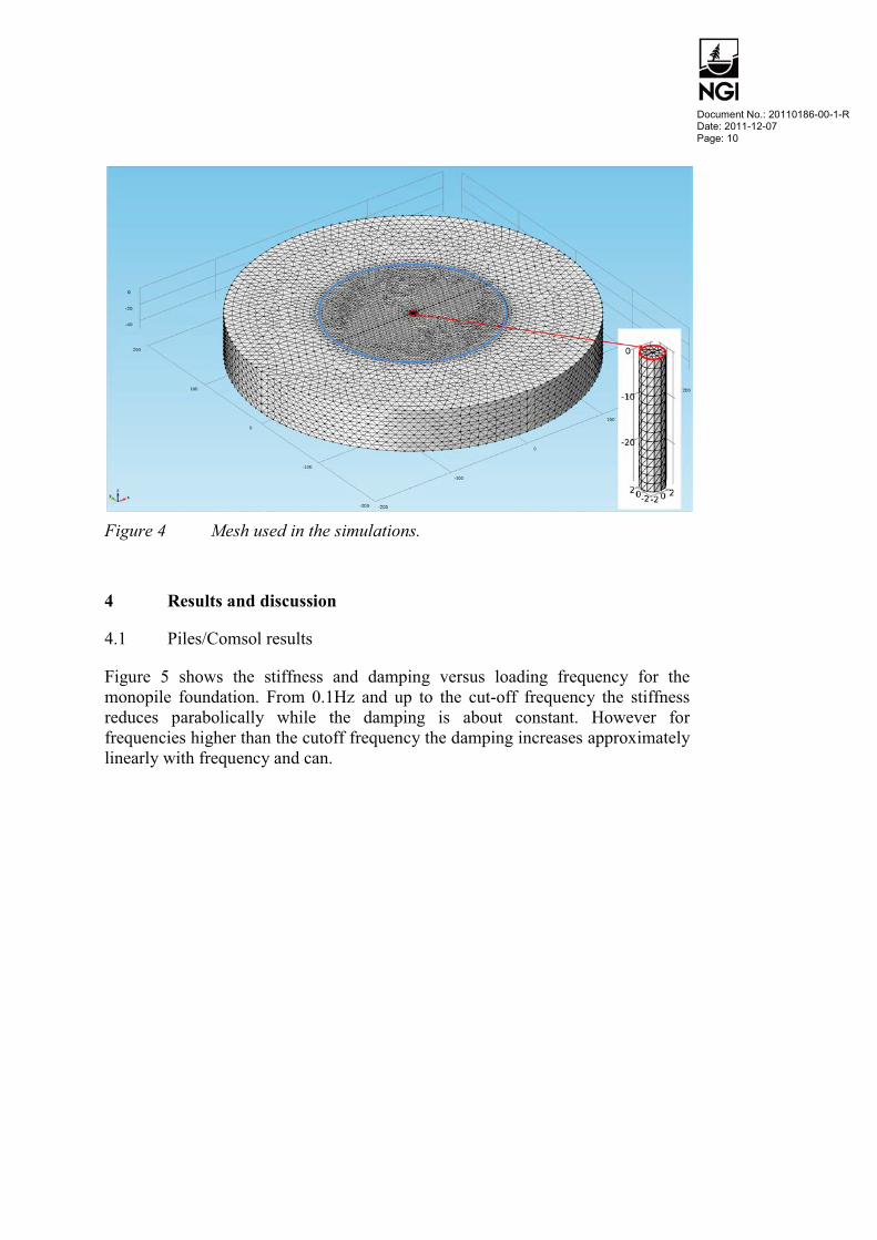
The linear elastic FE model shown in Figure 4 consists of solid elements for the soil and the pile is modeled with shell elements. Full contact between soil and pile is assumed. The domain outside blue ring are absorbing domain (so called PML). The lowest 10 m of the soil domaing beneat the pile is also and absorbing boundary. The loading frequency is varied from 0.1 Hz to 5 Hz. The larges element size set to be lower than 1/5 of the wavelength of shear waves at the highest frequency of 5 Hz. (100/5/5=4 m). The element size of the pile is set to 2 meter. (This may be course.) The number of degrees of freedom are some 300000. Computations were performed for 0.1Hz step between 0.1 and 4 Hz. The calculation time on the Z800-01 PC with 24 processor an 48 GB ram took about 10 hours. Horizontal or vertical point load was applied to the upper perimeter of the pile shown in red in the inset in Figure 4.

Document No.: 20110186-00-1-R Date: 2011-12-07 Page: 11
Figure 5 Comparison of horizontal stiffness and damping computed with
Piles and Comsol
Figure 6 show Mudline bending stress response spectra for a Blyth wind turbine (after [1]). The largest loads occur at frequencies from 0Hz to just above 1 Hz.
Figure 6 Mudline bending stress response spectra (after Jan Van Der Tempel [1])
0 0.5 1 1.5 2 2.5 3 3.5 4 4.5 50
2
4
6
8
10
12
1415 x 108
Frequency [Hz]
Stiff
ness
[N/m
]
Piles KxxComsol KxxPiles DxxComsol Dxx

Document No.: 20110186-00-1-R Date: 2011-12-07 Page: 12
4.2 Effect of shear strain on stiffness and damping
As seen in Figure 7 the shear strain is is larger closer to the pile. For a typical nonlinear soil behaviour this would result in a lower stiffness and higher material damping in the vicinity of the pile.
Figure 7 Logrithm of shear strains for 0.5Hz loading. Red color 1% strain
and blue color 1x10⁻³ %
Figure 8 Logrithm of shear strains for 2.4Hz loading. Red color 1% strain
and blue color 1x10⁻³ %
Figure 9 Logrithm of shear strains for 2.5Hz loading. Red color 1% strain and
blue color 1x10⁻³ %
Document No.: 20110186-00-1-R Date: 2011-12-07 Page: 13
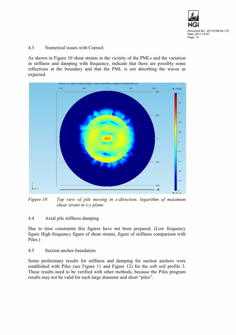
4.3 Numerical issues with Comsol
As shown in Figure 10 shear strains in the vicinity of the PMLs and the variation in stiffness and damping with frequency, indicate that there are possibly some reflections at the boundary and that the PML is not absorbing the waves as expected.
Figure 10 Top view of pile moving in x-direction, logarithm of maximum
shear strain in x-y plane 4.4 Axial pile stiffness damping
Due to time constraints this figures have not been prepared. (Low frequency figure High frequency figure of shear strains, figure of stiffness comparison with Piles.) 4.5 Suction anchor foundation
Some preliminary results for stiffness and damping for suction anchors were established with Piles (see Figure 11 and Figure 12) for the soft soil profile 3. These results need to be verified with other methods, because the Piles program results may not be valid for such large diameter and short “piles”.

Document No.: 20110186-00-1-R Date: 2011-12-07 Page: 14
Figure 11 Suction (Bucket) anchor horizontal stiffness and damping
Figure 12 Suction (bucket) anchor moment stiffness and damping
0 0.5 1 1.5 2 2.5 3 3.5 4 4.5 50
0.2
0.4
0.6
0.8
1
1.2
1.4
1.6
1.8
2 x 10⁹
Frequency [Hz]
Stiff
ness
and
dam
ping
kxx φ 10m h=5m Bucket Profile 3dxx φ 10m h=5m Bucket Profile 3kxx φ 5.2m Monopile Profile 3dxx φ 5.2m Monopile Profile 3
0 0.5 1 1.5 2 2.5 3 3.5 4 4.5 50
2
4
6
8
10
12
14 x 1010
Frequency [Hz]
Stiff
ness
and
dam
ping
Moment Stiffness Real and Imaginary
kmm φ 10m h=5 m Bucket Profile 3kmm φ 10m h=10m Bucket Profile 3kmm φ 5.2m Monopile Profile 3dmm φ 10m h=5 m Bucket Profile 3dmm φ 10m h=10m Bucket Profile 3dmm φ 5.2m Monopile Profile 3

Document No.: 20110186-00-1-R Date: 2011-12-07 Page: 15
5 Conclusions and ideas for future research
• Many load cases for OWT foundations are likely to have loads of frequencies below the cutoff frequency of soil deposits, e.g. see Figure 6, i.e. wave propagation will not contribute to damping.
• For some types of loading, slamming waves, pile-driving, dynamic effects do become important. This should be looked into further.
• For loading frequencies there is a spatial variation of shear strain, large near the pile and smaller further away. With increasing shear strain the shear modulus reduces and damping increases. The effect of this on the overall stiffness and damping should be evaluated in detail. To do this the absolute level of strain induced by different load cases has to be considered. Most likely non-linear effects are important and therefore a way to account for it in design should be developed.
• The stiffness varies with frequency also for frequencies below the cutoff frequency. Examples above show up to a 30% reduction compared to the static stiffness. This reduction of stiffness could possibly be modelled with an added mass in horizontal direction.
• Plots of shear strains around the pile (Figure 10) and the variation in stiffness and damping with frequency, indicate that there are some reflections at the boundary and that the PML is not absorbing the waves as expected. This should be further looked in to e.g. if Comsol is to be used further.
• Modelling soil in 3D is computationally expensive and the SSI method used for e.g. in the Maxlab IV project could be used also for obtaining global stiffness and damping
• Tools for computing stiffness of suction anchors should be looked into further.
Document No.: 20110186-00-1-R Date: 2011-12-07 Page: 16
6 References
[1] Jan Van Der Tempel, Design Of Support Structures For Offshore Wind Turbines, Ph.D. Thesis, ISBN 90-76468-11-7, 2006.
[2] Kaynia A.M., and Kausel, E., 1982, Dynamic behaviour of pile groups, Proceedings of the 2nd International Conference on Numerical Methods in Offshore Piling, University of Texas at Austin, April 29-30, 1982
[3] Kaynia, A.M., Green's Functions in Layered Media under Fluid. NGI Research Report, 514053-1, Dec. 18, 1996
[4] Comsol multiphysics 4.2, www.comsol.no

Kontroll- og referanseside/ Review and reference page
Skj.nr. 043
Dokumentinformasjon/Document information Dokumenttittel/Document title Soil Structure Interaction for OWT monopile foundation
Dokument nr/Document No. 20110186-00-1-R
Dokumenttype/Type of document Rapport/Report Teknisk notat/Technical Note
Distribusjon/Distribution Fri/Unlimited Begrenset/Limited Ingen/None
Dato/Date 2011.12.07 Rev.nr./Rev.No. 0
Oppdragsgiver/Client SP2 (NFR) Emneord/Keywords Piles, Laysac, Comsol, Stiffness, damping, cutoff frequency.
Stedfesting/Geographical information Land, fylke/Country, County
Havområde/Offshore area Kommune/Municipality
Feltnavn/Field name Sted/Location
Sted/Location Kartblad/Map
Felt, blokknr./Field, Block No. UTM-koordinater/UTM-coordinates
Dokumentkontroll/Document control Kvalitetssikring i henhold til/Quality assurance according to NS-EN ISO9001
Rev./ Rev. Revisjonsgrunnlag/Reason for revision
Egen-kontroll/
Self review av/by:
Sidemanns- kontroll/
Colleague review av/by:
Uavhengig kontroll/
Independent review av/by:
Tverrfaglig kontroll/
Inter-disciplinary
review av/by:
0 Original document JJo CM
Dokument godkjent for utsendelse/ Document approved for release
Dato/Date 2011.12.07
Sign. Prosjektleder/Project Manager Jörgen Johansson


Recommended