Solutions Manual for Fundamentals of Chemical Engineering Thermodynamics
Themis Matsoukas
Upper Saddle River, NJ • Boston • Indianapolis • San Francisco New York • Toronto • Montreal • London • Munich • Paris • Madrid Capetown • Sydney • Tokyo • Singapore • Mexico City
This text is associated with Themis Matsoukas, Fundamentals of Chemical Engineering Thermodynamics 0-13-269306-2 (978-0-13-269306-6). Copyright © 2013 Pearson Education, Inc. Do not redistribute.
Full file at http://testbank360.eu/solution-manual-fundamentals-of-chemical-engineering-thermodynamics-1st-edition-themis-matsoukas
Note to the Instructor An effort was made to update all solutions requiring steam tables to conform with the tables in Appendix E of the book, which are based on IAPWS95). It is possible, however, that some problems may make use of older tables. Be alert as such discrepancies could confuse students even though the final answers are not much different. Please report any mistakes or typos to Themis Matsoukas: [email protected]. The author and publisher have taken care in the preparation of this book, but make no expressed or implied warranty of any kind and assume no responsibility for errors or omissions No liability is assumed for incidental or consequential damages in connection with or arising out of the use of the information or programs contained herein. Visit us on the Web: InformIT.com/ph Copyright © 2013 Pearson Education, Inc. This work is protected by United States copyright laws and is provided solely for the use of instructors in teaching their courses and assessing student learning. Dissemination or sale of any part of this work (including on the World Wide Web) will destroy the integrity of the work and is not permitted. The work and materials from it should never be made available to students except by instructors using the accompanying text in their classes. All recipients of this work are expected to abide by these restrictions and to honor the intended pedagogical purposes and the needs of other instructors who rely on these materials. ISBN-10: 0-13-269320-8 ISBN-13: 978-0-13-269320-2
This text is associated with Themis Matsoukas, Fundamentals of Chemical Engineering Thermodynamics 0-13-269306-2 (978-0-13-269306-6). Copyright © 2013 Pearson Education, Inc. Do not redistribute.
Full file at http://testbank360.eu/solution-manual-fundamentals-of-chemical-engineering-thermodynamics-1st-edition-themis-matsoukas
Contents
1 Introduction 5
2 Phase Diagrams of Pure Fluids 13
3 Energy & the First Law 59
4 Entropy & the Second Law 103
5 Calculation of Properties 125
6 Balances in Open Systems 143
7 VLE of pure Fluid 193
8 Phase Behavior of Mixtures 223
9 Properties of Mixtures 245
10 VLE of Mixture 271
11 Ideal Solution 291
12 Non-Ideal Solution 311
13 Miscibility, Solubility and other Phase Equilibria 347
14 Reactions 371
3This text is associated with Themis Matsoukas, Fundamentals of Chemical Engineering Thermodynamics 0-13-269306-2 (978-0-13-269306-6). Copyright © 2013 Pearson Education, Inc. Do not redistribute.
Full file at http://testbank360.eu/solution-manual-fundamentals-of-chemical-engineering-thermodynamics-1st-edition-themis-matsoukas

This text is associated with Themis Matsoukas, Fundamentals of Chemical Engineering Thermodynamics 0-13-269306-2 (978-0-13-269306-6). Copyright © 2013 Pearson Education, Inc. Do not redistribute.
Full file at http://testbank360.eu/solution-manual-fundamentals-of-chemical-engineering-thermodynamics-1st-edition-themis-matsoukas
1 Introduction
5This text is associated with Themis Matsoukas, Fundamentals of Chemical Engineering Thermodynamics 0-13-269306-2 (978-0-13-269306-6). Copyright © 2013 Pearson Education, Inc. Do not redistribute.
Full file at http://testbank360.eu/solution-manual-fundamentals-of-chemical-engineering-thermodynamics-1st-edition-themis-matsoukas
1. INTRODUCTION
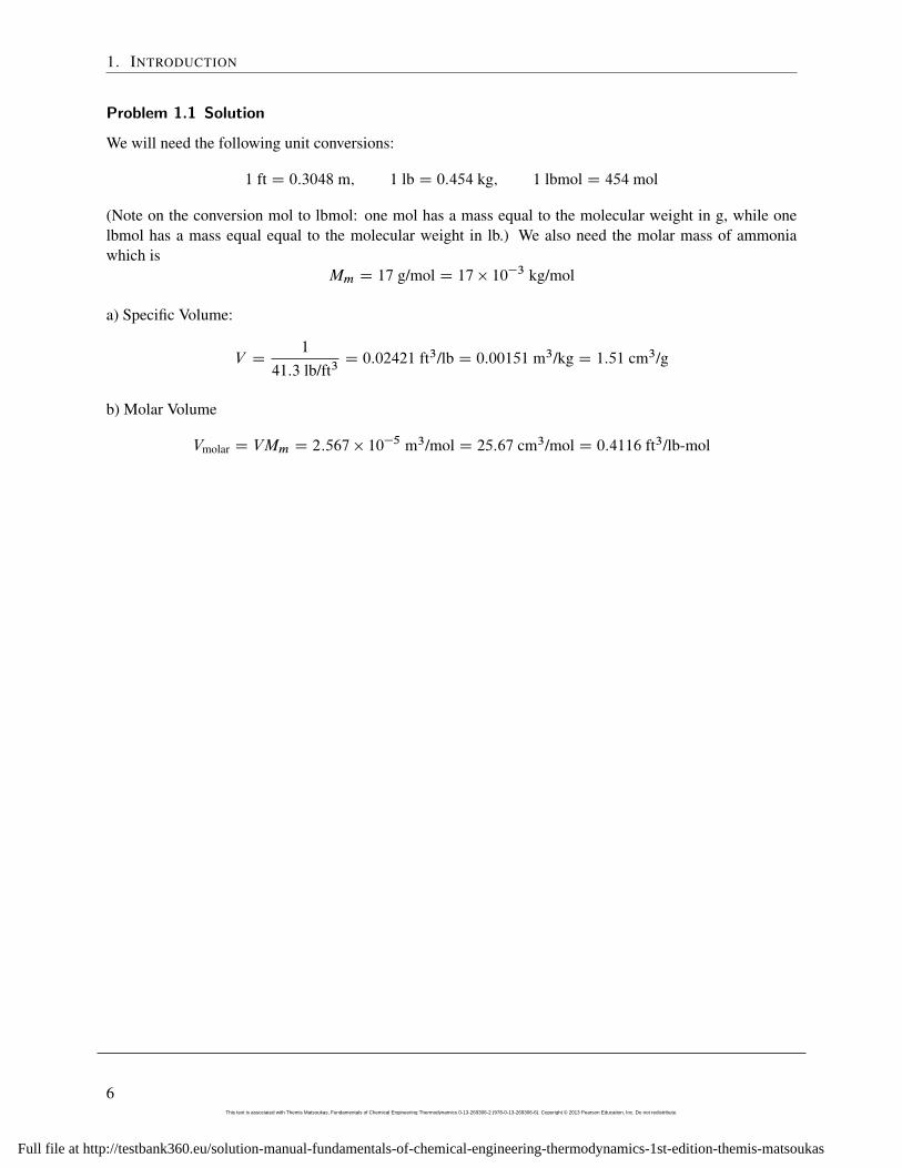
Problem 1.1 Solution
We will need the following unit conversions:
1 ft D 0:3048 m; 1 lb D 0:454 kg; 1 lbmol D 454 mol
(Note on the conversion mol to lbmol: one mol has a mass equal to the molecular weight in g, while onelbmol has a mass equal equal to the molecular weight in lb.) We also need the molar mass of ammoniawhich is
Mm D 17 g/mol D 17 � 10�3 kg/mol
a) Specific Volume:
V D1
41:3 lb/ft3D 0:02421 ft3/lb D 0:00151 m3/kg D 1:51 cm3/g
b) Molar Volume
Vmolar D VMm D 2:567 � 10�5 m3/mol D 25:67 cm3/mol D 0:4116 ft3/lb-mol
6This text is associated with Themis Matsoukas, Fundamentals of Chemical Engineering Thermodynamics 0-13-269306-2 (978-0-13-269306-6). Copyright © 2013 Pearson Education, Inc. Do not redistribute.
Full file at http://testbank360.eu/solution-manual-fundamentals-of-chemical-engineering-thermodynamics-1st-edition-themis-matsoukas
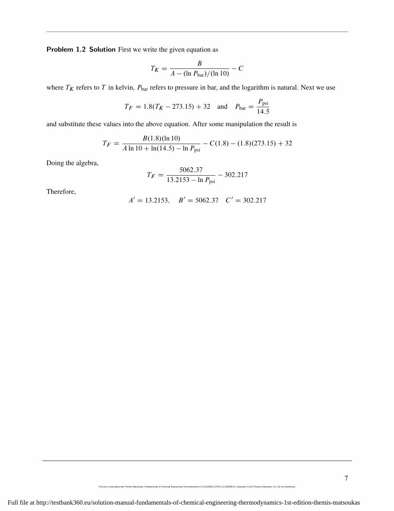
Problem 1.2 Solution First we write the given equation as
TK DB
A � .lnPbar/=.ln 10/� C
where TK refers to T in kelvin, Pbar refers to pressure in bar, and the logarithm is natural. Next we use
TF D 1:8.TK � 273:15/C 32 and Pbar DPpsi
14:5
and substitute these values into the above equation. After some manipulation the result is
TF DB.1:8/.ln 10/
A ln 10C ln.14:5/ � lnPpsi� C.1:8/ � .1:8/.273:15/C 32
Doing the algebra,
TF D5062:37
13:2153 � lnPpsi� 302:217
Therefore,A0 D 13:2153; B 0 D 5062:37 C 0 D 302:217
7This text is associated with Themis Matsoukas, Fundamentals of Chemical Engineering Thermodynamics 0-13-269306-2 (978-0-13-269306-6). Copyright © 2013 Pearson Education, Inc. Do not redistribute.
Full file at http://testbank360.eu/solution-manual-fundamentals-of-chemical-engineering-thermodynamics-1st-edition-themis-matsoukas
1. INTRODUCTION
Problem 1.3 Solution a) The mean velocity is
Nv D
�8kBT
�m
�1=2where kB D 1:38 � 10�23 J=K, T D 273:16 K. The mass of the water molecule is
m DMm
NAVD
18 � 10�3 kg=mol6:022 � 1023 mol�1 D 2:98904 � 10
�26 kg:
The mean velocity isNv D 566:699 m=s D 2040:12 km=h D 1267 mph
This result depends only on temperature and since all three phases are the same temperature, molecules havethe same mean velocity in all three phases.
b) The mean kinetic energy isNEkin D
12mv2 D 1
2mv2
where v2 is the mean squared velocity,
v2 D3kBT
m:
With this the mean kinetic energy is
NEkin D3
2kBT D 5:65441 � 10
�21 J
This is the mean kinetic energy per molecule in all phases. The number of molecules in 1 kg of water is
N D1 kg
18 � 10�3 kg=mol6=022 � 1023 D 3:34556 � 1025
The total kinetic energy in 1 kg of water at 0.01 ıC (regardless of phase) is
NEkin D�5:65441 � 10�21 J
� �3:34556 � 1025
�D 189; 171 J D 189 kJ
Comment: This is the translational kinetic energy of the molecule, i.e., the kinetic energy due to themotion of the center of mass. A water molecule possesses additional forms of kinetic energy that arisefrom the rotation of the molecule, the bending of bonds, and the vibration of oxygen and hydrogen atomsabout their equilibrium positions. These are not included in this calculation as the Maxwell-Boltzmanndistribution refers specifically to the translational kinetic energy.
c) The above calculation shows that the mean kinetic energy depends only on temperature (it is independentof pressure or of the mass of the molecule). Therefore, oxygen at 0.01 ıC has the same kinetic energy aswater at the same temperature:
NEkin D3
2kBT D 5:65441 � 10
�21 J
8This text is associated with Themis Matsoukas, Fundamentals of Chemical Engineering Thermodynamics 0-13-269306-2 (978-0-13-269306-6). Copyright © 2013 Pearson Education, Inc. Do not redistribute.
Full file at http://testbank360.eu/solution-manual-fundamentals-of-chemical-engineering-thermodynamics-1st-edition-themis-matsoukas
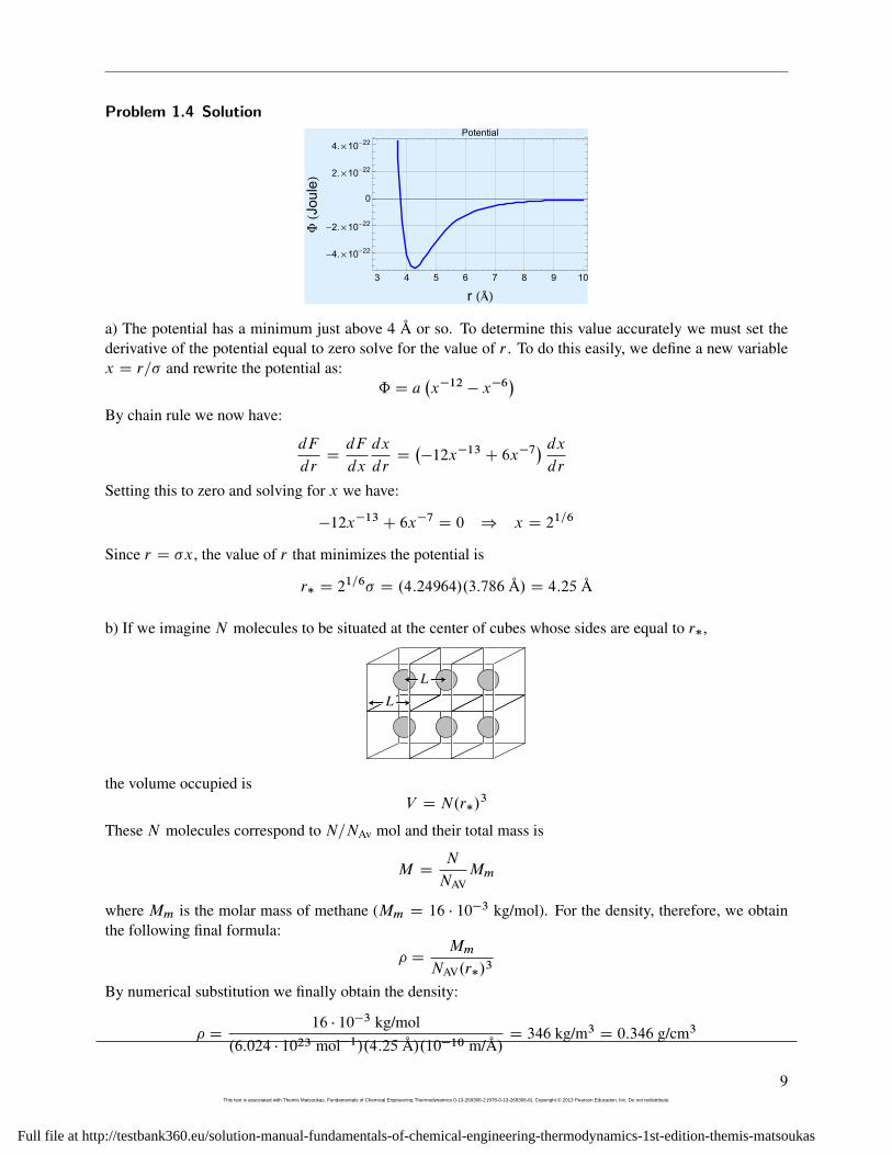
Problem 1.4 Solution
3 4 5 6 7 8 9 10
-4.´10-22
-2.´10-22
0
2.´10-22
4.´10-22
r HÞLF
HJo
ule
L
Potential
a) The potential has a minimum just above 4 A or so. To determine this value accurately we must set thederivative of the potential equal to zero solve for the value of r . To do this easily, we define a new variablex D r=� and rewrite the potential as:
ˆ D a�x�12 � x�6
�By chain rule we now have:
dF
drDdF
dx
dx
drD��12x�13 C 6x�7
� dxdr
Setting this to zero and solving for x we have:
�12x�13 C 6x�7 D 0 ) x D 21=6
Since r D �x, the value of r that minimizes the potential is
r� D 21=6� D .4:24964/.3:786 A/ D 4:25 A
b) If we imagine N molecules to be situated at the center of cubes whose sides are equal to r�,
L
L
the volume occupied isV D N.r�/
3
These N molecules correspond to N=NAv mol and their total mass is
M DN
NAVMm
where Mm is the molar mass of methane (Mm D 16 � 10�3 kg/mol). For the density, therefore, we obtainthe following final formula:
� DMm
NAV.r�/3
By numerical substitution we finally obtain the density:
� D16 � 10�3 kg/mol
.6:024 � 1023 mol�1/.4:25 A/.10�10 m/A/D 346 kg/m3 D 0:346 g/cm3
9This text is associated with Themis Matsoukas, Fundamentals of Chemical Engineering Thermodynamics 0-13-269306-2 (978-0-13-269306-6). Copyright © 2013 Pearson Education, Inc. Do not redistribute.
Full file at http://testbank360.eu/solution-manual-fundamentals-of-chemical-engineering-thermodynamics-1st-edition-themis-matsoukas
1. INTRODUCTION
c) Specific volumes of saturated liquid methane are listed in Perry’s Handbook from which we can computethe densities. We notice (as we would have expected) that liquid volumes near the critical point (Tc D190:55 K) vary with pressure, from 162.3 kg/m3 at the critical point to 454 kg/m3 around 90 K. Our valuecorresponds to Perry’s tabulation at about 160 K. Our calculation is approximate and does not incorporatethe effect of pressure and temperature. Notice that if we pick a distance somewhat different from r� theresult will change quite a bit because if the third power to which this distance is raised. But the importantconclusion is that the calculation placed the density right in the correct range between the lowest and highestvalues listed in the tables. This says that our molecular picture of the liquid, however idealized, is fairly closeto reality.
10This text is associated with Themis Matsoukas, Fundamentals of Chemical Engineering Thermodynamics 0-13-269306-2 (978-0-13-269306-6). Copyright © 2013 Pearson Education, Inc. Do not redistribute.
Full file at http://testbank360.eu/solution-manual-fundamentals-of-chemical-engineering-thermodynamics-1st-edition-themis-matsoukas
Problem 1.5 Solution
Assuming molecules to be sitting at the center of a cubic lattice with spacing L, the volume occupied by Nmolecules is NL3 and the density is
� DMm
NAVL3
where Mm is the molar mass. Solving for the intermolecular distance,
L D
�Mm
NAV�
�a) For liquid water with � D 1000 kg=m3,
L D
�18 � 10�3 kg=mol
.6:022 � 1023 mol�1/.1000 kg=m3/
�1=3D 3:10 � 10�10 m D 3:01 A
b) For steam with � D 0:4 kg=m3
L D
�18 � 10�3 kg=mol
.6:022 � 1023 mol�1/.0:4 kg=m3/
�1=3D 4:2 � 10�9 m D 42 A
The intermolecular distance is about 10 times larger in the vapor.
11This text is associated with Themis Matsoukas, Fundamentals of Chemical Engineering Thermodynamics 0-13-269306-2 (978-0-13-269306-6). Copyright © 2013 Pearson Education, Inc. Do not redistribute.
Full file at http://testbank360.eu/solution-manual-fundamentals-of-chemical-engineering-thermodynamics-1st-edition-themis-matsoukas
1. INTRODUCTION
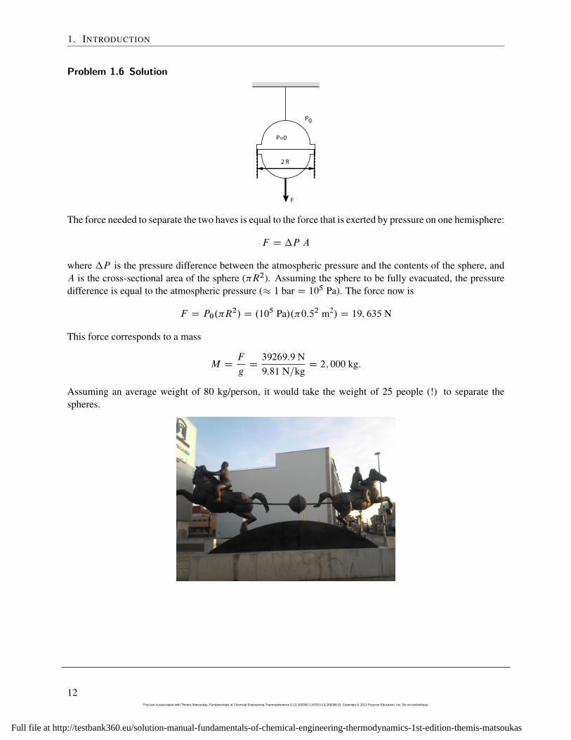
Problem 1.6 Solution
F
P0
P=0
2 R
The force needed to separate the two haves is equal to the force that is exerted by pressure on one hemisphere:
F D �P A
where �P is the pressure difference between the atmospheric pressure and the contents of the sphere, andA is the cross-sectional area of the sphere (�R2). Assuming the sphere to be fully evacuated, the pressuredifference is equal to the atmospheric pressure (� 1 bar D 105 Pa). The force now is
F D P0.�R2/ D .105 Pa/.�0:52 m2/ D 19; 635 N
This force corresponds to a mass
M DF
gD39269:9 N9:81 N=kg
D 2; 000 kg:
Assuming an average weight of 80 kg/person, it would take the weight of 25 people (!) to separate thespheres.
12This text is associated with Themis Matsoukas, Fundamentals of Chemical Engineering Thermodynamics 0-13-269306-2 (978-0-13-269306-6). Copyright © 2013 Pearson Education, Inc. Do not redistribute.
Full file at http://testbank360.eu/solution-manual-fundamentals-of-chemical-engineering-thermodynamics-1st-edition-themis-matsoukas
2 Phase Diagrams of Pure Fluids
13This text is associated with Themis Matsoukas, Fundamentals of Chemical Engineering Thermodynamics 0-13-269306-2 (978-0-13-269306-6). Copyright © 2013 Pearson Education, Inc. Do not redistribute.
Full file at http://testbank360.eu/solution-manual-fundamentals-of-chemical-engineering-thermodynamics-1st-edition-themis-matsoukas
2. PHASE DIAGRAMS OF PURE FLUIDS
Problem 2.1 Solution a) 25 ıC, 1 bar: liquid, because the temperature is below the saturation temperatureat 1 bar (99.63ıC).
10 bar, 80ıC: liquid, because the temperature is below the saturation temperature at 10 bar (179.88 ıC).
120 ıC, 50 bar: At 120 ıC the vapor pressure is 198.54 kPa = 1.9884 bar. Since the actual pressure is higher,the state is liquid. (Or, at 50 bar the saturation temperature is 263.91 ıC. Since the actual temperature islower the state is liquid.)
b) Liquid, because the pressure (1 atm = 760 mm Hg) is higher than the vapor pressure of bromobenzene(10 mg H) at the same temperature.
c) Liquid, because the temperature is lower than the boiling point at the same pressure.
Note: All of these statements will make better sense if you plot your information on the PV graph.
14This text is associated with Themis Matsoukas, Fundamentals of Chemical Engineering Thermodynamics 0-13-269306-2 (978-0-13-269306-6). Copyright © 2013 Pearson Education, Inc. Do not redistribute.
Full file at http://testbank360.eu/solution-manual-fundamentals-of-chemical-engineering-thermodynamics-1st-edition-themis-matsoukas
Problem 2.2 Solution a) From steam tables at 40 bar we collect the following data:
600 ıC 650 ıC40 bar 0:0989 m3=kg 0:1049 m3=kg
By interpolation at V D 100 g=cm3 D 0:1 m3=kg we find
T D 600C650 � 600
0:1049 � 0:0989.0:1 � 0:0989/ D 609:2 ıC
The system is at 40 bar, 609.2 ıC: the phase is vapor.
b) At 6 bar we find that the desired volume lies between that of the saturated liquid (VL D 0:0011 m3=kg)and saturated vapor (VV D 0:3156): the system is a vapor/liquid mixture. The vapor and liquid fractions areobtained by lever rule:
xL D0:3156 � 0:1
0:3156 � 0:0011D 0:314 D 31:4%
xV D 1 � 0:314 D 0:686 D 68:6%
15This text is associated with Themis Matsoukas, Fundamentals of Chemical Engineering Thermodynamics 0-13-269306-2 (978-0-13-269306-6). Copyright © 2013 Pearson Education, Inc. Do not redistribute.
Full file at http://testbank360.eu/solution-manual-fundamentals-of-chemical-engineering-thermodynamics-1st-edition-themis-matsoukas
2. PHASE DIAGRAMS OF PURE FLUIDS
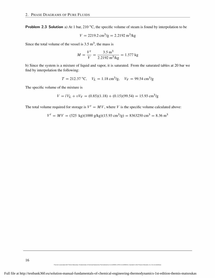
Problem 2.3 Solution a) At 1 bar, 210 ıC, the specific volume of steam is found by interpolation to be
V D 2219:2 cm3/g D 2:2192 m3/kg
Since the total volume of the vessel is 3.5 m3, the mass is
M DV t
VD
3:5 m3
2:2192 m3/kgD 1:577 kg
b) Since the system is a mixture of liquid and vapor, it is saturated. From the saturated tables at 20 bar wefind by interpolation the following:
T D 212:37 ıC; VL D 1:18 cm3/g; VV D 99:54 cm3/g
The specific volume of the mixture is
V D lVL C vVV D .0:85/.1:18/C .0:15/.99:54/ D 15:93 cm3/g
The total volume required for storage is V t DMV , where V is the specific volume calculated above:
V t DMV D .525 kg/.1000 g/kg/.15:93 cm3/g/ D 8363250 cm3 D 8:36 m3
16This text is associated with Themis Matsoukas, Fundamentals of Chemical Engineering Thermodynamics 0-13-269306-2 (978-0-13-269306-6). Copyright © 2013 Pearson Education, Inc. Do not redistribute.
Full file at http://testbank360.eu/solution-manual-fundamentals-of-chemical-engineering-thermodynamics-1st-edition-themis-matsoukas
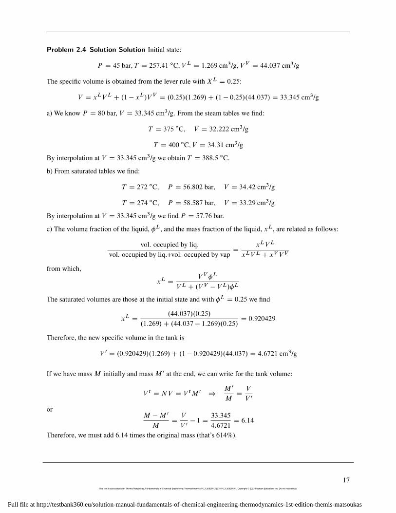
Problem 2.4 Solution Solution Initial state:
P D 45 bar; T D 257:41 ıC; V L D 1:269 cm3/g; V V D 44:037 cm3/g
The specific volume is obtained from the lever rule with XL D 0:25:
V D xLV L C .1 � xL/V V D .0:25/.1:269/C .1 � 0:25/.44:037/ D 33:345 cm3/g
a) We know P D 80 bar, V D 33:345 cm3/g. From the steam tables we find:
T D 375 ıC; V D 32:222 cm3/g
T D 400 ıC; V D 34:31 cm3/g
By interpolation at V D 33:345 cm3/g we obtain T D 388:5 ıC.
b) From saturated tables we find:
T D 272 ıC; P D 56:802 bar; V D 34:42 cm3/g
T D 274 ıC; P D 58:587 bar; V D 33:29 cm3/g
By interpolation at V D 33:345 cm3/g we find P D 57:76 bar.
c) The volume fraction of the liquid, �L, and the mass fraction of the liquid, xL, are related as follows:
vol. occupied by liq.vol. occupied by liq.+vol. occupied by vap
DxLV L
xLV L C xV V V
from which,
xL DV V �L
V L C .V V � V L/�L
The saturated volumes are those at the initial state and with �L D 0:25 we find
xL D.44:037/.0:25/
.1:269/C .44:037 � 1:269/.0:25/D 0:920429
Therefore, the new specific volume in the tank is
V 0 D .0:920429/.1:269/C .1 � 0:920429/.44:037/ D 4:6721 cm3/g
If we have mass M initially and mass M 0 at the end, we can write for the tank volume:
V t D NV D V tM 0 )M 0
MDV
V 0
orM �M 0
MDV
V 0� 1 D
33:345
4:6721D 6:14
Therefore, we must add 6.14 times the original mass (that’s 614%).
17This text is associated with Themis Matsoukas, Fundamentals of Chemical Engineering Thermodynamics 0-13-269306-2 (978-0-13-269306-6). Copyright © 2013 Pearson Education, Inc. Do not redistribute.
Full file at http://testbank360.eu/solution-manual-fundamentals-of-chemical-engineering-thermodynamics-1st-edition-themis-matsoukas
2. PHASE DIAGRAMS OF PURE FLUIDS
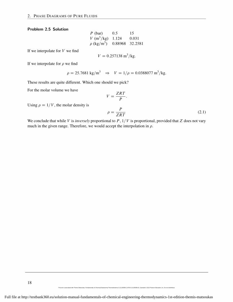
Problem 2.5 SolutionP .bar/ 0:5 15
V .m3=kg/ 1:124 0:031
� .kg=m3/ 0:88968 32:2581
If we interpolate for V we findV D 0:257138 m3=kg:
If we interpolate for � we find
� D 25:7681 kg=m3) V D 1=� D 0:0388077 m3=kg:
These results are quite different. Which one should we pick?
For the molar volume we haveV D
ZRT
P:
Using � D 1=V , the molar density is
� DP
ZRT(2.1)
We conclude that while V is inversely proportional to P , 1=V is proportional, provided thatZ does not varymuch in the given range. Therefore, we would accept the interpolation in �.
18This text is associated with Themis Matsoukas, Fundamentals of Chemical Engineering Thermodynamics 0-13-269306-2 (978-0-13-269306-6). Copyright © 2013 Pearson Education, Inc. Do not redistribute.
Full file at http://testbank360.eu/solution-manual-fundamentals-of-chemical-engineering-thermodynamics-1st-edition-themis-matsoukas
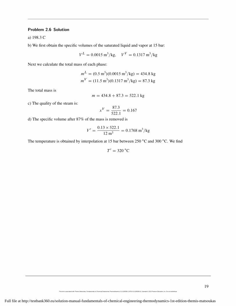
Problem 2.6 Solution
a) 198.3 C
b) We first obtain the specific volumes of the saturated liquid and vapor at 15 bar:
V L D 0:0015 m3=kg; V V D 0:1317 m3=kg
Next we calculate the total mass of each phase:
mL D .0:5 m3/.0:0015 m3=kg/ D 434:8 kg
mV D .11:5 m3/.0:1317 m3=kg/ D 87:3 kg
The total mass ism D 434:8C 87:3 D 522:1 kg
c) The quality of the steam is:
xV D87:3
522:1D 0:167
d) The specific volume after 87% of the mass is removed is
V 0 D0:13 � 522:1
12 m3 D 0:1768 m3=kg
The temperature is obtained by interpolation at 15 bar between 250 ıC and 300 ıC. We find
T 0 D 320 ıC
19This text is associated with Themis Matsoukas, Fundamentals of Chemical Engineering Thermodynamics 0-13-269306-2 (978-0-13-269306-6). Copyright © 2013 Pearson Education, Inc. Do not redistribute.
Full file at http://testbank360.eu/solution-manual-fundamentals-of-chemical-engineering-thermodynamics-1st-edition-themis-matsoukas
2. PHASE DIAGRAMS OF PURE FLUIDS
Problem 2.7 Solution a) Since the cooker contains both vapor and liquid, the state is saturated steam.Therefore, T D T sat D 120:23 ıC.
b) From steam tables we obtain the specific volumes of the saturated phasees:
V L D 1:061 cm3/g; V V D 885:44 cm3/g
The total volume of the liquid in the cooker is V L;tot D .0:25/.8/ liter = 2000 cm3. Therefore, the mass ofthe liquid is
mL DV L;tot
V LD2000
1:061D 1885:0 g
The volume of the vapor in the cooker is V L;tot D .0:75/.8/ liter = 6000 cm3 and its mass is given by
mV DV L;tot
V VD
6000
885:44D 6:78 g
The total mass is
m D 1885:0C 6:78 D 1891:78 g D 1:89 kg
c) The mass fractions of the liquid (xL), and of the vapor (xV ) are
xL D1885:0
1885:0C 6:78D 0:9964 D 99:64%; xV D 1 � xL D 0:004 D 0:4%
Even though the vapor occupies 75% of the volume, it only represents 0.4% of the total mass.
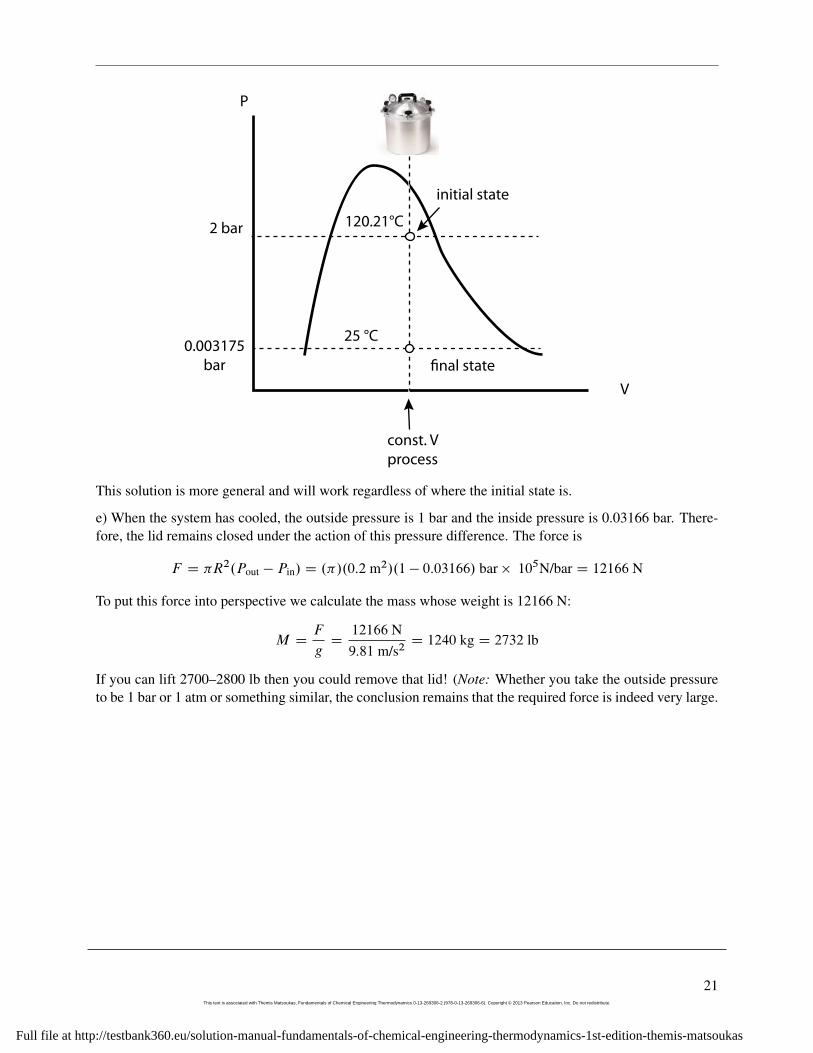
d) The quick solution is to take a look at the PV graph. The initial state is at A and the final state, B , isreached by constant-volume cooling. This state is obviously in the two-phase region because the originatingstate was also inside that region as well. We conclude that P D P sat.25 ıC/ D 3:166 kPa. (If, however,state A were in the superheated region, we would be able to tell if B is superheated or vapor/liquid and wewould have to do the solution in more detail as shown below.)
Detailed solution: The total volume of the system as well as the specific volume remain constant. Thespecific volume is
V DVcooker
MtotD8000 cm3
1891:78 gD 4:229 cm3/g
From the saturated steam tables at 25 ıC we find, V L D 1:003 cm3/g, V V D 43400 cm3/g. The specificvolume of the system is between these two values, therefore we still have a saturated system. We concludethat P D P sat.25 ıC/ D 3:166 kPaD 0:03166 bar.
20This text is associated with Themis Matsoukas, Fundamentals of Chemical Engineering Thermodynamics 0-13-269306-2 (978-0-13-269306-6). Copyright © 2013 Pearson Education, Inc. Do not redistribute.
Full file at http://testbank360.eu/solution-manual-fundamentals-of-chemical-engineering-thermodynamics-1st-edition-themis-matsoukas
P
V
initial state
const. V
process
�nal state
2 bar 120.21°C
25 °C0.003175
bar
This solution is more general and will work regardless of where the initial state is.
e) When the system has cooled, the outside pressure is 1 bar and the inside pressure is 0.03166 bar. There-fore, the lid remains closed under the action of this pressure difference. The force is
F D �R2.Pout � Pin/ D .�/.0:2 m2/.1 � 0:03166/ bar � 105N/bar D 12166 N
To put this force into perspective we calculate the mass whose weight is 12166 N:
M DF
gD
12166 N9:81 m/s2
D 1240 kg D 2732 lb
If you can lift 2700–2800 lb then you could remove that lid! (Note: Whether you take the outside pressureto be 1 bar or 1 atm or something similar, the conclusion remains that the required force is indeed very large.
21This text is associated with Themis Matsoukas, Fundamentals of Chemical Engineering Thermodynamics 0-13-269306-2 (978-0-13-269306-6). Copyright © 2013 Pearson Education, Inc. Do not redistribute.
Full file at http://testbank360.eu/solution-manual-fundamentals-of-chemical-engineering-thermodynamics-1st-edition-themis-matsoukas
2. PHASE DIAGRAMS OF PURE FLUIDS
Problem 2.8 Solution
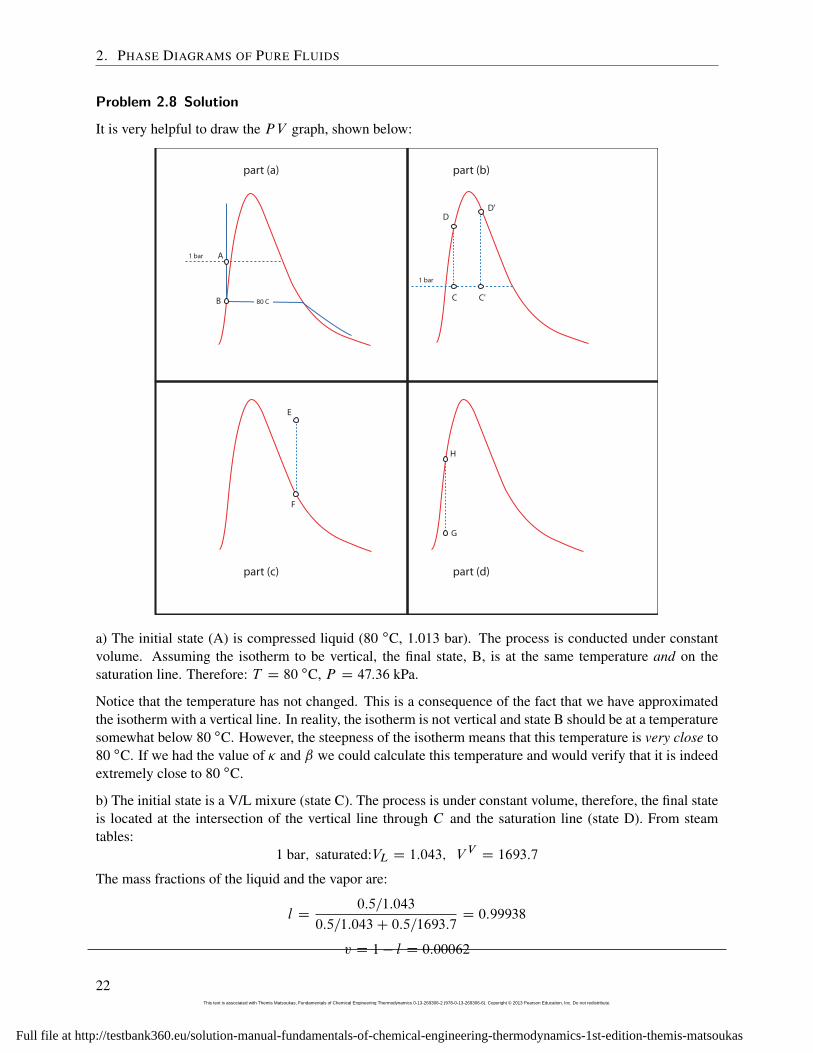
It is very helpful to draw the PV graph, shown below:
1 bar A
B 80 C
1 bar
C
D'
C'
D
E
F
G
H
part (a) part (b)
part (c) part (d)
a) The initial state (A) is compressed liquid (80 ıC, 1.013 bar). The process is conducted under constantvolume. Assuming the isotherm to be vertical, the final state, B, is at the same temperature and on thesaturation line. Therefore: T D 80 ıC, P D 47:36 kPa.
Notice that the temperature has not changed. This is a consequence of the fact that we have approximatedthe isotherm with a vertical line. In reality, the isotherm is not vertical and state B should be at a temperaturesomewhat below 80 ıC. However, the steepness of the isotherm means that this temperature is very close to80 ıC. If we had the value of � and ˇ we could calculate this temperature and would verify that it is indeedextremely close to 80 ıC.
b) The initial state is a V/L mixure (state C). The process is under constant volume, therefore, the final stateis located at the intersection of the vertical line through C and the saturation line (state D). From steamtables:
1 bar; saturated:VL D 1:043; V V D 1693:7
The mass fractions of the liquid and the vapor are:
l D0:5=1:043
0:5=1:043C 0:5=1693:7D 0:99938
v D 1 � l D 0:00062
22This text is associated with Themis Matsoukas, Fundamentals of Chemical Engineering Thermodynamics 0-13-269306-2 (978-0-13-269306-6). Copyright © 2013 Pearson Education, Inc. Do not redistribute.
Full file at http://testbank360.eu/solution-manual-fundamentals-of-chemical-engineering-thermodynamics-1st-edition-themis-matsoukas
The specific volume at the initial state is (in cm3/g)
V D .0:99938/.1:043/C .0:00062/.1693:7/ D 2:085
At the final state: V D 2:085, and saturated. From steam tables we find, T � 367 ıC, P D 203:13 bar(saturated liquid).
Note 1: Even though the mass fraction of the vapor is very nearly 0, it would not be correct to set it equal to0. While v is small, when multiplied by a large V V it makes a significant contribution to the specificvolume of the mixture. If we had set v �, we would have concluded that the initial state is practicallysaturated liquid which means that the final pressure is almost 1 bar. Clearly, this approximation missesthe right pressure by more than 200 bar!!!
Note 2: In this case the specific volume of the vapor-liquid mixture was very close to the liquid side and forthis reason the final state was liquid. In other words, under heating the vapor condenses and becomesliquid. If, however, the initial volume was much closer the vapor side (state C’), then heating wouldproduce vapor. In this case, heating would cause the liquid to evaporate. That is, after heating thecontents of the vessel the final state might either saturated vapor or saturated liquid. Can you establisha criterion for the initial specific volume to determine whether the final state is vapor or liquid?
c) The final state saturated vapor (state F). The process is cooling under constant volume, therefore, theinitial state must be somewhere on the vertical line through F and above point F (since cooling implies thatthe initial state is at higher T ). We conclude the initial state is superheated vapor.
d) By similar arguments as above, we determine that the initial state is vapor/liquid mixture. Notice thathere we are heating a vapor/liquid mixture and as a result the vapor condenses to produce saturated liquid!
23This text is associated with Themis Matsoukas, Fundamentals of Chemical Engineering Thermodynamics 0-13-269306-2 (978-0-13-269306-6). Copyright © 2013 Pearson Education, Inc. Do not redistribute.
Full file at http://testbank360.eu/solution-manual-fundamentals-of-chemical-engineering-thermodynamics-1st-edition-themis-matsoukas
2. PHASE DIAGRAMS OF PURE FLUIDS
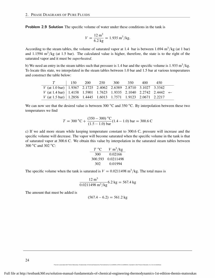
Problem 2.9 Solution The specific volume of water under these conditions in the tank is
V D12 m3
6:2 kgD 1:935 m3=kg:
According to the steam tables, the volume of saturated vapor at 1.4 bar is between 1.694 m3=kg (at 1 bar)and 1.1594 m3=kg (at 1.5 bar). The calculated value is higher, therefore, the state is to the right of thesaturated vapor and it must be superheated.
b) We need an entry in the steam tables such that pressure is 1.4 bar and the specific volume is 1:935m3=kg.To locate this state, we interpolated in the steam tables between 1.0 bar and 1.5 bar at various temperaturesand construct the table below:
T 150 200 250 300 350 400 450
V .at 1:0 bar/ 1:9367 2:1725 2:4062 2:6389 2:8710 3:1027 3:3342
V .at 1:4 bar/ 1:4158 1:5901 1:7623 1:9335 2:1040 2:2742 2:4442
V .at 1:5 bar/ 1:2856 1:4445 1:6013 1:7571 1:9123 2:0671 2:2217
We can now see that the desired value is between 300 ıC and 350 ıC. By interpolation between these twotemperatures we find
T D 300 ıCC.350 � 300/ ıC.1:5 � 1:0/ bar
.1:4 � 1:0/ bar D 300:6 C
c) If we add more steam while keeping temperature constant to 300.6 C, pressure will increase and thespecific volume will decrease. The vapor will become saturated when the specific volume in the tank is thatof saturated vapor at 300.6 C. We obtain this value by interpolation in the saturated steam tables between300 ıC and 302 ıC:
T ıC V m3=kg300 0:02166
300:593 0:0211498
302 0:01994
The specific volume when the tank is saturated is V D 0:0211498 m3=kg. The total mass is
12 m3
0:0211498 m3=kg6:2 kg D 567:4 kg
The amount that must be added is.567:4 � 6:2/ D 561:2 kg
24This text is associated with Themis Matsoukas, Fundamentals of Chemical Engineering Thermodynamics 0-13-269306-2 (978-0-13-269306-6). Copyright © 2013 Pearson Education, Inc. Do not redistribute.
Full file at http://testbank360.eu/solution-manual-fundamentals-of-chemical-engineering-thermodynamics-1st-edition-themis-matsoukas

Problem 2.10 Solution Solution
The graphs below show the PV in various combinations of linear and logarithmic coordinates and the ZPgraph.
1.0
0.8
0.6
0.4
0.2
0.0
Com
pre
ssib
ility F
acto
r
250200150100500
Pressure (bar)
100 C
200 C
300 C
400 C
0.01
0.1
1
10
100
1000
Pre
ssu
re (
ba
r)
100
101
102
103
104
105
Specific volume (cm3/g)
100 C
200 C
300 C
400 C
250
200
150
100
50
0
Pre
ssu
re (
ba
r)
12 4 6
102 4 6
1002 4 6
1000
Specific volume (cm3/g)
100 C200 C
300 C
400 C
250
200
150
100
50
0
Pre
ssu
re (
ba
r)
100806040200
Specific volume (cm3/g)
100 C
200 C
300 C
400 C
Comments:
� The volumes span a very wide range and in order to see the shape of the saturation line, we must plotonly a smaller range. In the above graph, the volume axis ranges from 0 to 100 cm3/mol.
� By doing the V axis in log coordinates we can now look at a very wide range of values withoutsqueezing the graph into nothingness. Notice that in the log plot the volume goes from 1 to 100,000cm3/g.
� The steam tables do not contain data for the compressed liquid region and so our isotherms stop at thesaturated liquid. We could extrapolate them into the liquid by drawing them as vertical lines.
� The ZP graph has the familiar look. Notice that the isotherms are better separated on this graph.
25This text is associated with Themis Matsoukas, Fundamentals of Chemical Engineering Thermodynamics 0-13-269306-2 (978-0-13-269306-6). Copyright © 2013 Pearson Education, Inc. Do not redistribute.
Full file at http://testbank360.eu/solution-manual-fundamentals-of-chemical-engineering-thermodynamics-1st-edition-themis-matsoukas
2. PHASE DIAGRAMS OF PURE FLUIDS
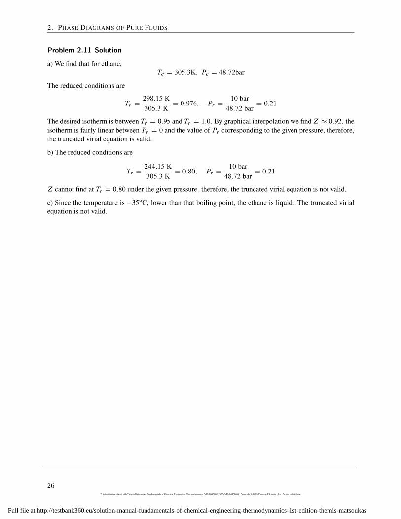
Problem 2.11 Solution
a) We find that for ethane,Tc D 305:3K; Pc D 48:72bar
The reduced conditions are
Tr D298:15 K305:3 K
D 0:976; Pr D10 bar48:72 bar
D 0:21
The desired isotherm is between Tr D 0:95 and Tr D 1:0. By graphical interpolation we findZ � 0:92. theisotherm is fairly linear between Pr D 0 and the value of Pr corresponding to the given pressure, therefore,the truncated virial equation is valid.
b) The reduced conditions are
Tr D244:15 K305:3 K
D 0:80; Pr D10 bar48:72 bar
D 0:21
Z cannot find at Tr D 0:80 under the given pressure. therefore, the truncated virial equation is not valid.
c) Since the temperature is �35ıC, lower than that boiling point, the ethane is liquid. The truncated virialequation is not valid.
26This text is associated with Themis Matsoukas, Fundamentals of Chemical Engineering Thermodynamics 0-13-269306-2 (978-0-13-269306-6). Copyright © 2013 Pearson Education, Inc. Do not redistribute.
Full file at http://testbank360.eu/solution-manual-fundamentals-of-chemical-engineering-thermodynamics-1st-edition-themis-matsoukas
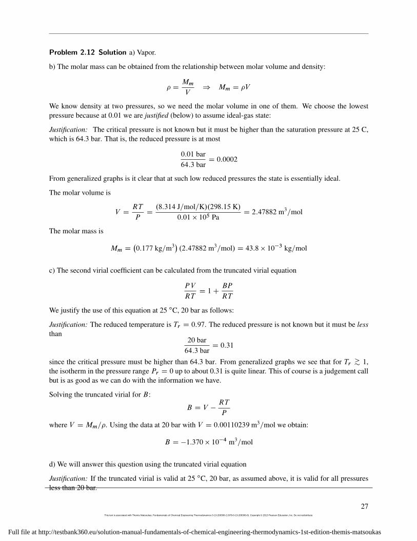
Problem 2.12 Solution a) Vapor.
b) The molar mass can be obtained from the relationship between molar volume and density:
� DMm
V) Mm D �V
We know density at two pressures, so we need the molar volume in one of them. We choose the lowestpressure because at 0.01 we are justified (below) to assume ideal-gas state:
Justification: The critical pressure is not known but it must be higher than the saturation pressure at 25 C,which is 64.3 bar. That is, the reduced pressure is at most
0:01 bar64:3 bar
D 0:0002
From generalized graphs is it clear that at such low reduced pressures the state is essentially ideal.
The molar volume is
V DRT
PD.8:314 J=mol=K/.298:15 K/
0:01 � 105 PaD 2:47882 m3=mol
The molar mass is
Mm D�0:177 kg=m3� .2:47882 m3=mol/ D 43:8 � 10�3 kg=mol
c) The second virial coefficient can be calculated from the truncated virial equation
PV
RTD 1C
BP
RT
We justify the use of this equation at 25 ıC, 20 bar as follows:
Justification: The reduced temperature is Tr D 0:97. The reduced pressure is not known but it must be lessthan
20 bar64:3 bar
D 0:31
since the critical pressure must be higher than 64.3 bar. From generalized graphs we see that for Tr >� 1,the isotherm in the pressure range Pr D 0 up to about 0.31 is quite linear. This of course is a judgement callbut is as good as we can do with the information we have.
Solving the truncated virial for B:
B D V �RT
P
where V DMm=�. Using the data at 20 bar with V D 0:00110239 m3=mol we obtain:
B D �1:370 � 10�4 m3=mol
d) We will answer this question using the truncated virial equation
Justification: If the truncated virial is valid at 25 ıC, 20 bar, as assumed above, it is valid for all pressuresless than 20 bar.
27This text is associated with Themis Matsoukas, Fundamentals of Chemical Engineering Thermodynamics 0-13-269306-2 (978-0-13-269306-6). Copyright © 2013 Pearson Education, Inc. Do not redistribute.
Full file at http://testbank360.eu/solution-manual-fundamentals-of-chemical-engineering-thermodynamics-1st-edition-themis-matsoukas
2. PHASE DIAGRAMS OF PURE FLUIDS
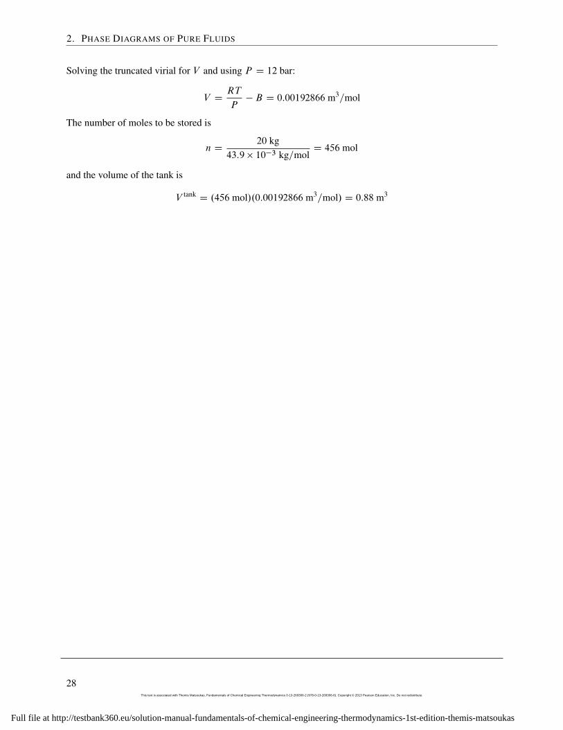
Solving the truncated virial for V and using P D 12 bar:
V DRT
P� B D 0:00192866 m3=mol
The number of moles to be stored is
n D20 kg
43:9 � 10�3 kg=molD 456 mol
and the volume of the tank is
V tankD .456 mol/.0:00192866 m3=mol/ D 0:88 m3
28This text is associated with Themis Matsoukas, Fundamentals of Chemical Engineering Thermodynamics 0-13-269306-2 (978-0-13-269306-6). Copyright © 2013 Pearson Education, Inc. Do not redistribute.
Full file at http://testbank360.eu/solution-manual-fundamentals-of-chemical-engineering-thermodynamics-1st-edition-themis-matsoukas
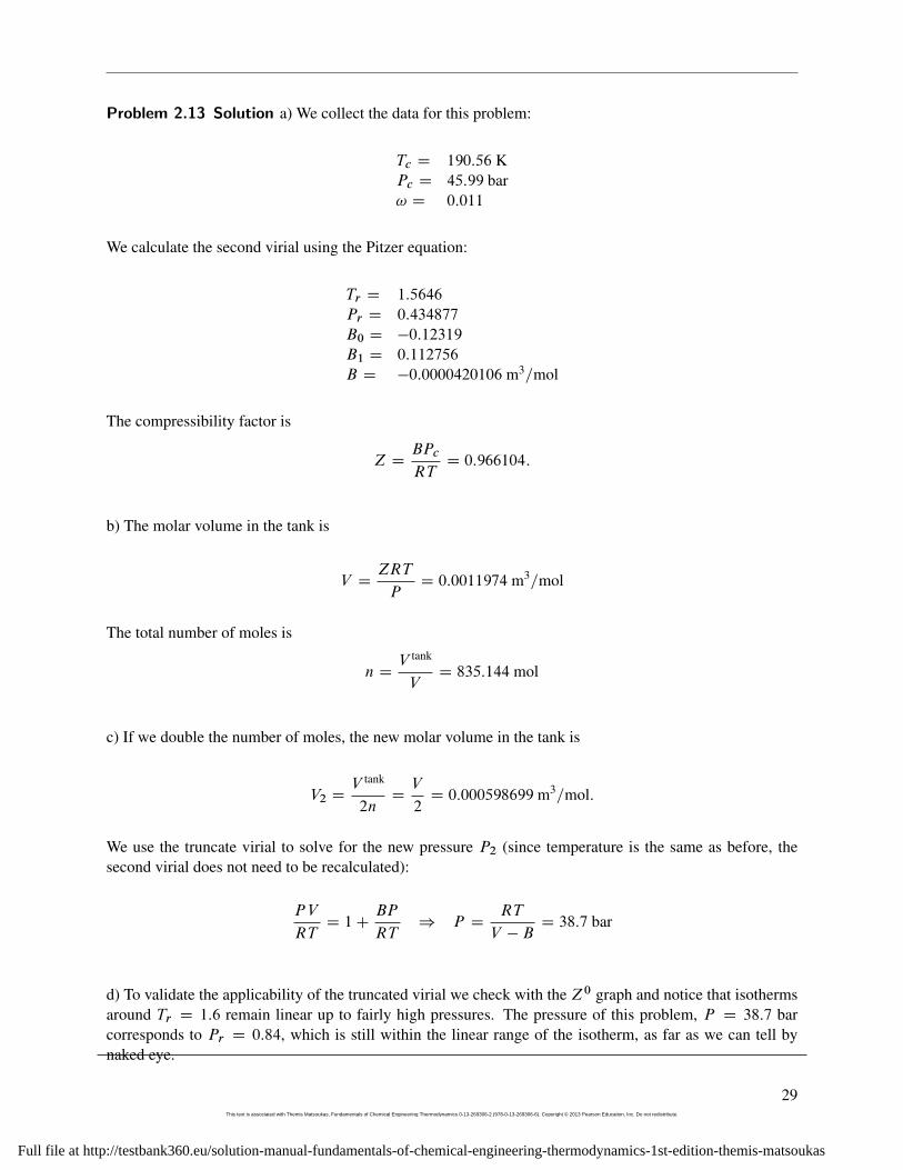
Problem 2.13 Solution a) We collect the data for this problem:
Tc D 190:56 KPc D 45:99 bar! D 0:011
We calculate the second virial using the Pitzer equation:
Tr D 1:5646
Pr D 0:434877
B0 D �0:12319
B1 D 0:112756
B D �0:0000420106 m3=mol
The compressibility factor is
Z DBPc
RTD 0:966104:
b) The molar volume in the tank is
V DZRT
PD 0:0011974 m3=mol
The total number of moles is
n DV tank
VD 835:144 mol
c) If we double the number of moles, the new molar volume in the tank is
V2 DV tank
2nDV
2D 0:000598699 m3=mol:
We use the truncate virial to solve for the new pressure P2 (since temperature is the same as before, thesecond virial does not need to be recalculated):
PV
RTD 1C
BP
RT) P D
RT
V � BD 38:7 bar
d) To validate the applicability of the truncated virial we check with the Z0 graph and notice that isothermsaround Tr D 1:6 remain linear up to fairly high pressures. The pressure of this problem, P D 38:7 barcorresponds to Pr D 0:84, which is still within the linear range of the isotherm, as far as we can tell bynaked eye.
29This text is associated with Themis Matsoukas, Fundamentals of Chemical Engineering Thermodynamics 0-13-269306-2 (978-0-13-269306-6). Copyright © 2013 Pearson Education, Inc. Do not redistribute.
Full file at http://testbank360.eu/solution-manual-fundamentals-of-chemical-engineering-thermodynamics-1st-edition-themis-matsoukas
2. PHASE DIAGRAMS OF PURE FLUIDS
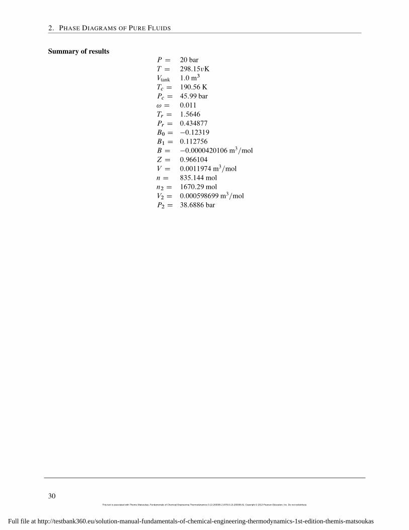
Summary of resultsP D 20 barT D 298:15vKVtank 1:0 m3
Tc D 190:56 KPc D 45:99 bar! D 0:011
Tr D 1:5646
Pr D 0:434877
B0 D �0:12319
B1 D 0:112756
B D �0:0000420106 m3=molZ D 0:966104
V D 0:0011974 m3=moln D 835:144 moln2 D 1670:29 molV2 D 0:000598699 m3=molP2 D 38:6886 bar
30This text is associated with Themis Matsoukas, Fundamentals of Chemical Engineering Thermodynamics 0-13-269306-2 (978-0-13-269306-6). Copyright © 2013 Pearson Education, Inc. Do not redistribute.
Full file at http://testbank360.eu/solution-manual-fundamentals-of-chemical-engineering-thermodynamics-1st-edition-themis-matsoukas
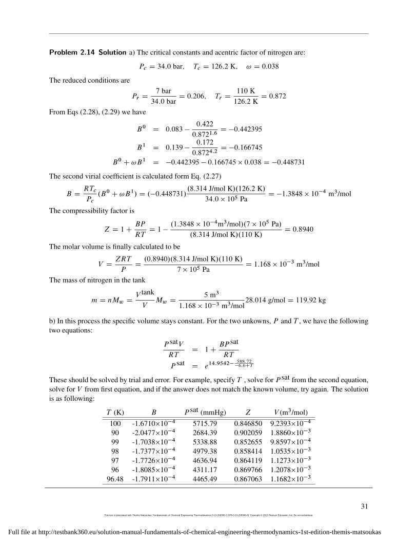
Problem 2.14 Solution a) The critical constants and acentric factor of nitrogen are:
Pc D 34:0 bar; Tc D 126:2 K; ! D 0:038
The reduced conditions are
Pr D7 bar34:0 bar
D 0:206; Tr D110 K126:2 K
D 0:872
From Eqs (2.28), (2.29) we have
B0 D 0:083 �0:422
0:8721:6D �0:442395
B1 D 0:139 �0:172
0:8724:2D �0:166745
B0 C !B1 D �0:442395 � 0:166745 � 0:038 D �0:448731
The second virial coefficient is calculated form Eq. (2.27)
B DRTc
Pc.B0 C !B1/ D .�0:448731/
.8:314 J/mol K/.126:2 K/34:0 � 105 Pa
D �1:3848 � 10�4 m3/mol
The compressibility factor is
Z D 1CBP
RTD 1 �
.1:3848 � 10�4m3/mol/.7 � 105 Pa/.8:314 J/mol K/.110 K/
D 0:8940
The molar volume is finally calculated to be
V DZRT
PD.0:8940/.8:314 J/mol K/.110 K/
7 � 105 PaD 1:168 � 10�3 m3/mol
The mass of nitrogen in the tank
m D nMw DV tank
VMw D
5 m3
1:168 � 10�3 m3/mol28:014 g/mol D 119:92 kg
b) In this process the specific volume stays constant. For the two unkowns, P and T , we have the followingtwo equations:
P satVRT
D 1CBP sat
RT
P satD e14:9542�
588:72�6:6CT
These should be solved by trial and error. For example, specify T , solve for P sat from the second equation,solve for V from first equation, and if the answer does not match the known volume, try again. The solutionis as following:
T (K) B P sat (mmHg) Z V (m3/mol)100 -1.6710�10�4 5715.79 0.846850 9.2393�10�4
90 -2.0477�10�4 2684.39 0.902059 1.8860�10�3
99 -1.7038�10�4 5338.88 0.852655 9.8597�10�4
98 -1.7377�10�4 4979.38 0.858414 1.0535�10�3
97 -1.7726�10�4 4636.94 0.864119 1.1273�10�3
96 -1.8085�10�4 4311.17 0.869766 1.2078�10�3
96.48 -1.7911�10�4 4465.49 0.867063 1.1682�10�3
31This text is associated with Themis Matsoukas, Fundamentals of Chemical Engineering Thermodynamics 0-13-269306-2 (978-0-13-269306-6). Copyright © 2013 Pearson Education, Inc. Do not redistribute.
Full file at http://testbank360.eu/solution-manual-fundamentals-of-chemical-engineering-thermodynamics-1st-edition-themis-matsoukas
2. PHASE DIAGRAMS OF PURE FLUIDS
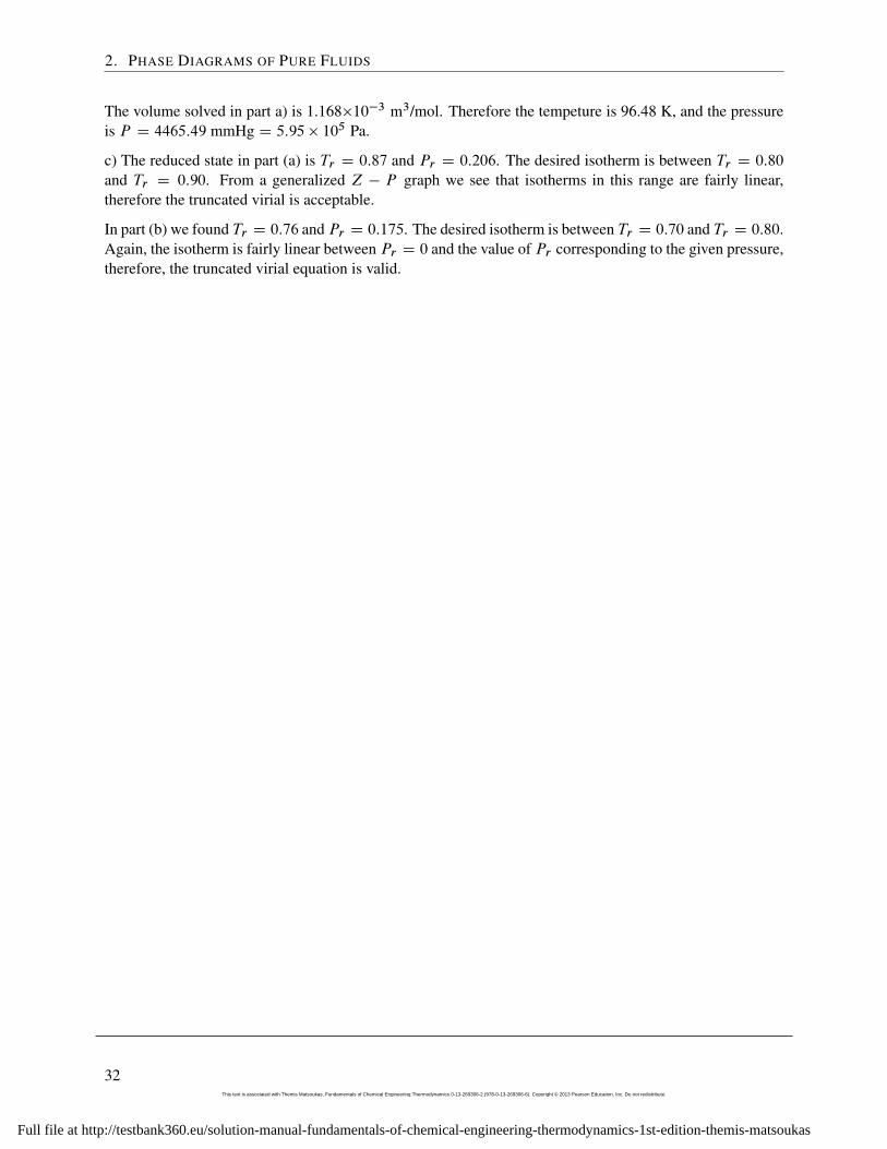
The volume solved in part a) is 1.168�10�3 m3/mol. Therefore the tempeture is 96.48 K, and the pressureis P D 4465:49 mmHg D 5:95 � 105 Pa.
c) The reduced state in part (a) is Tr D 0:87 and Pr D 0:206. The desired isotherm is between Tr D 0:80
and Tr D 0:90. From a generalized Z � P graph we see that isotherms in this range are fairly linear,therefore the truncated virial is acceptable.
In part (b) we found Tr D 0:76 and Pr D 0:175. The desired isotherm is between Tr D 0:70 and Tr D 0:80.Again, the isotherm is fairly linear between Pr D 0 and the value of Pr corresponding to the given pressure,therefore, the truncated virial equation is valid.
32This text is associated with Themis Matsoukas, Fundamentals of Chemical Engineering Thermodynamics 0-13-269306-2 (978-0-13-269306-6). Copyright © 2013 Pearson Education, Inc. Do not redistribute.
Full file at http://testbank360.eu/solution-manual-fundamentals-of-chemical-engineering-thermodynamics-1st-edition-themis-matsoukas
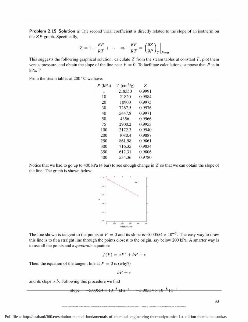
Problem 2.15 Solution a) The second virial coefficient is directly related to the slope of an isotherm onthe ZP graph. Specifically,
Z D 1CBP
RTC � � � )
BP
RTD
�@Z
@P
�T
ˇPD0
This suggests the following graphical solution: calculate Z from the steam tables at constant T , plot themversus pressure, and obtain the slope of the line near P D 0. To facilitate calculations, suppose that P is inkPa, V
From the steam tables at 200 ıC we have:
P (kPa) V (cm3/g) Z
1 218350 0.999110 21820 0.998420 10900 0.997530 7267.5 0.997640 5447.8 0.997150 4356. 0.996675 2900.2 0.9953100 2172.3 0.9940200 1080.4 0.9887250 861.98 0.9861300 716.35 0.9834350 612.31 0.9806400 534.36 0.9780
Notice that we had to go up to 400 kPa (4 bar) to see enough change in Z so that we can obtain the slope ofthe line. The graph is shown below:
1.00
0.99
0.98
0.97
0.96
0.95
Z
5004003002001000
Pressure (kPa)
200 C
The line shown is tangent to the points at P D 0 and its slope is�5:00554 � 10�5. The easy way to drawthis line is to fit a straight line through the points closest to the origin, say below 200 kPa. A smarter way isto use all the points and a quadratic equation:
f .P / D aP 2 C bP C c
Then, the equation of the tangent line at P D 0 is (why?)
bP C c
and its slope is b. Following this procedure we find
slope D �5:00554 � 10�5 kPa�1 D �5:00554 � 10�8 Pa�1
33This text is associated with Themis Matsoukas, Fundamentals of Chemical Engineering Thermodynamics 0-13-269306-2 (978-0-13-269306-6). Copyright © 2013 Pearson Education, Inc. Do not redistribute.
Full file at http://testbank360.eu/solution-manual-fundamentals-of-chemical-engineering-thermodynamics-1st-edition-themis-matsoukas
2. PHASE DIAGRAMS OF PURE FLUIDS
The second virial coefficient is
B D .slope/.RT / D .�5:00554 � 10�8 Pa�1/.8:314 J/mol K/.473:15 K/ D �1:969 � 10�4 m3/mol
b) Using the above value of B we can calculate the molar volume of water at 14 bar as follows:
PV
RTD 1C
BP
RT)
V DRT
PC B D
.8:314 J/mol K/.473:15 K/14 � 105 Pa
� 1:969 � 10�4 m3/mol
D 2:613 � 10�3 m3/mol
D 145:15 cm3/g
The value from the steam tables is 142.94 cm3/g. This agreement is very good indicating that the truncatedvirial equation is valid at these conditions.
34This text is associated with Themis Matsoukas, Fundamentals of Chemical Engineering Thermodynamics 0-13-269306-2 (978-0-13-269306-6). Copyright © 2013 Pearson Education, Inc. Do not redistribute.
Full file at http://testbank360.eu/solution-manual-fundamentals-of-chemical-engineering-thermodynamics-1st-edition-themis-matsoukas
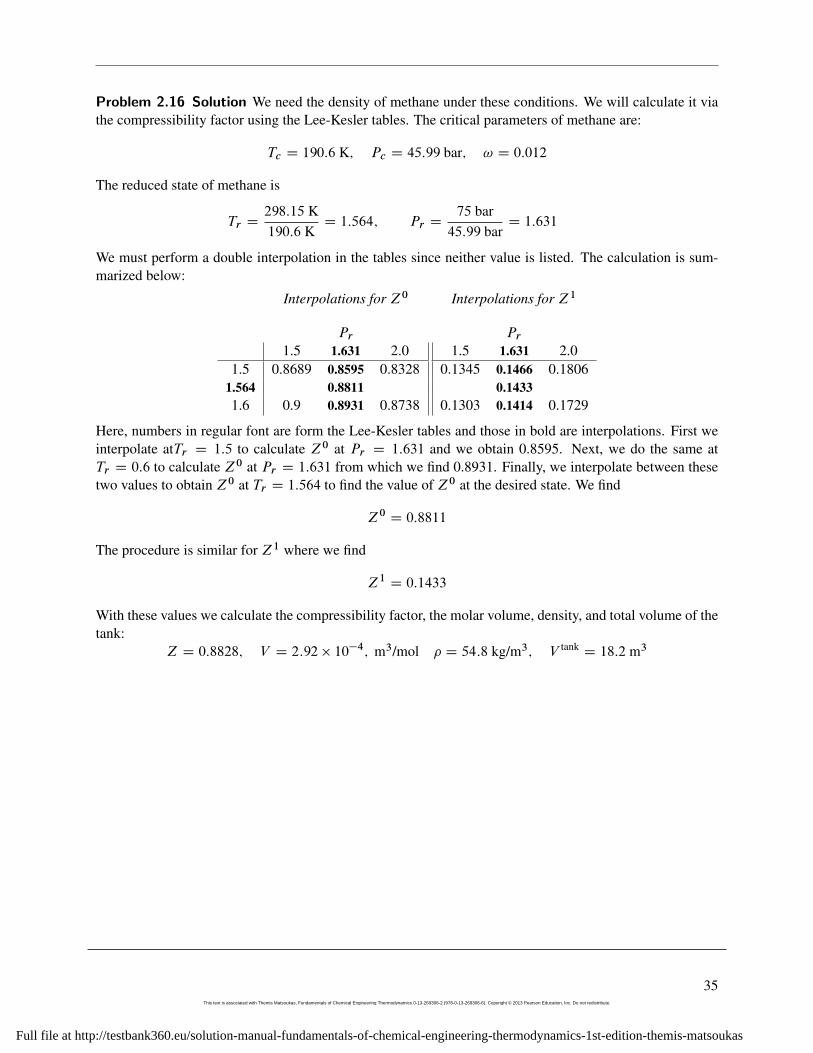
Problem 2.16 Solution We need the density of methane under these conditions. We will calculate it viathe compressibility factor using the Lee-Kesler tables. The critical parameters of methane are:
Tc D 190:6 K; Pc D 45:99 bar; ! D 0:012
The reduced state of methane is
Tr D298:15 K190:6 K
D 1:564; Pr D75 bar45:99 bar
D 1:631
We must perform a double interpolation in the tables since neither value is listed. The calculation is sum-marized below:
Interpolations for Z0
Pr1.5 1.631 2.0
1.5 0.8689 0.8595 0.83281.564 0.88111.6 0.9 0.8931 0.8738
Interpolations for Z1
Pr1.5 1.631 2.0
0.1345 0.1466 0.18060.1433
0.1303 0.1414 0.1729
Here, numbers in regular font are form the Lee-Kesler tables and those in bold are interpolations. First weinterpolate atTr D 1:5 to calculate Z0 at Pr D 1:631 and we obtain 0.8595. Next, we do the same atTr D 0:6 to calculate Z0 at Pr D 1:631 from which we find 0.8931. Finally, we interpolate between thesetwo values to obtain Z0 at Tr D 1:564 to find the value of Z0 at the desired state. We find
Z0 D 0:8811
The procedure is similar for Z1 where we find
Z1 D 0:1433
With these values we calculate the compressibility factor, the molar volume, density, and total volume of thetank:
Z D 0:8828; V D 2:92 � 10�4; m3/mol � D 54:8 kg/m3; V tankD 18:2 m3
35This text is associated with Themis Matsoukas, Fundamentals of Chemical Engineering Thermodynamics 0-13-269306-2 (978-0-13-269306-6). Copyright © 2013 Pearson Education, Inc. Do not redistribute.
Full file at http://testbank360.eu/solution-manual-fundamentals-of-chemical-engineering-thermodynamics-1st-edition-themis-matsoukas
2. PHASE DIAGRAMS OF PURE FLUIDS
Problem 2.17 Solution a) At the given conditions, Tr D 0:963675, Pr D 0:949281. The state is veryclose to the critical, therefore, far removed from the ideal-gas state.
b) Using the Lee Kesler method we find
Z0 D 0:381614;
Z1 D �0:597626;
Z D 0:247148;
V D 0:0000860517 m3=mol
The number of moles in the tank is
n D200 kg
4410�3 kg=molD 4545:45 mol
and the volume of the tank is
V tankD V n D 0:391 m3
c) At 25 ıC, 1 bar, CO2 is essentially in the ideal-gas state and its molar volume is
V2 DRT
P2D 0:0243725 m3
which means that the moles in th tank are
n2 DV tank
V2D 16:048 mol ) m2 D 0:706 kg
We must remove 199:294s kg.
36This text is associated with Themis Matsoukas, Fundamentals of Chemical Engineering Thermodynamics 0-13-269306-2 (978-0-13-269306-6). Copyright © 2013 Pearson Education, Inc. Do not redistribute.
Full file at http://testbank360.eu/solution-manual-fundamentals-of-chemical-engineering-thermodynamics-1st-edition-themis-matsoukas
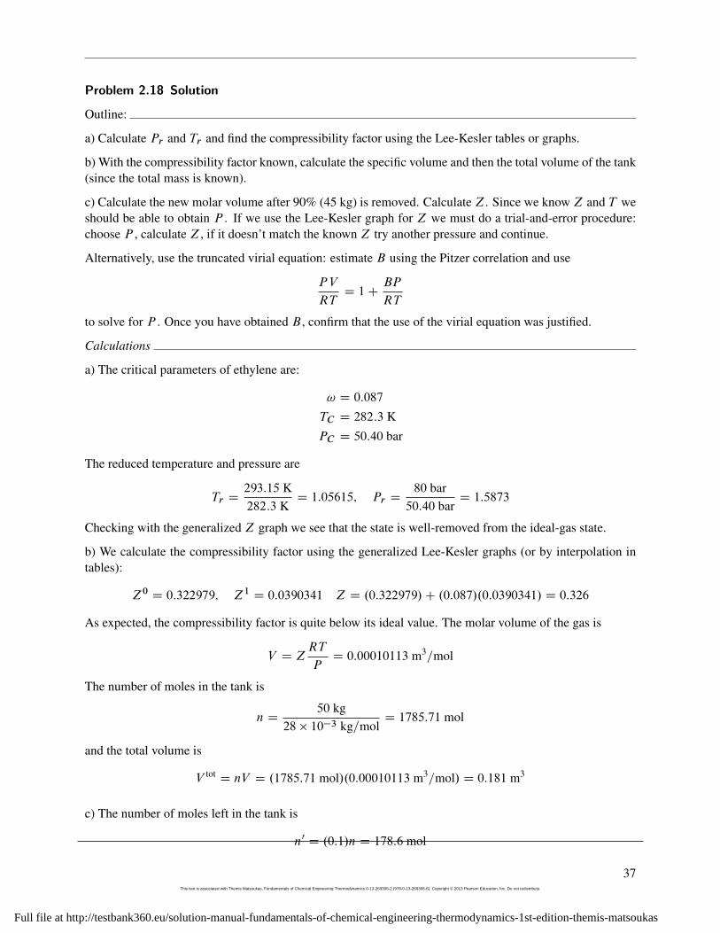
Problem 2.18 Solution
Outline:
a) Calculate Pr and Tr and find the compressibility factor using the Lee-Kesler tables or graphs.
b) With the compressibility factor known, calculate the specific volume and then the total volume of the tank(since the total mass is known).
c) Calculate the new molar volume after 90% (45 kg) is removed. Calculate Z. Since we know Z and T weshould be able to obtain P . If we use the Lee-Kesler graph for Z we must do a trial-and-error procedure:choose P , calculate Z, if it doesn’t match the known Z try another pressure and continue.
Alternatively, use the truncated virial equation: estimate B using the Pitzer correlation and use
PV
RTD 1C
BP
RT
to solve for P . Once you have obtained B , confirm that the use of the virial equation was justified.
Calculations
a) The critical parameters of ethylene are:
! D 0:087
TC D 282:3 K
PC D 50:40 bar
The reduced temperature and pressure are
Tr D293:15 K282:3 K
D 1:05615; Pr D80 bar50:40 bar
D 1:5873
Checking with the generalized Z graph we see that the state is well-removed from the ideal-gas state.
b) We calculate the compressibility factor using the generalized Lee-Kesler graphs (or by interpolation intables):
Z0 D 0:322979; Z1 D 0:0390341 Z D .0:322979/C .0:087/.0:0390341/ D 0:326
As expected, the compressibility factor is quite below its ideal value. The molar volume of the gas is
V D ZRT
PD 0:00010113 m3=mol
The number of moles in the tank is
n D50 kg
28 � 10�3 kg=molD 1785:71 mol
and the total volume is
V totD nV D .1785:71 mol/.0:00010113 m3=mol/ D 0:181 m3
c) The number of moles left in the tank is
n0 D .0:1/n D 178:6 mol
37This text is associated with Themis Matsoukas, Fundamentals of Chemical Engineering Thermodynamics 0-13-269306-2 (978-0-13-269306-6). Copyright © 2013 Pearson Education, Inc. Do not redistribute.
Full file at http://testbank360.eu/solution-manual-fundamentals-of-chemical-engineering-thermodynamics-1st-edition-themis-matsoukas
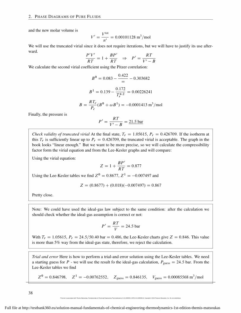
2. PHASE DIAGRAMS OF PURE FLUIDS
and the new molar volume is
V 0 DV tot
n0D 0:00101128 m3=mol
We will use the truncated virial since it does not require iterations, but we will have to justify its use after-ward.
P 0V 0
RTD 1C
BP 0
RT) P 0 D
RT
V 0 � B
We calculate the second virial coefficient using the Pitzer correlation:
B0 D 0:083 �0:422
D� 0:303682
B1 D 0:139 �0:172
T 4:2rD 0:00226241
B DRTc
Pc.B0 C !B1/ D �0:0001413 m3=mol
Finally, the pressure is
P 0 DRT
V 0 � BD 21:5 bar
Check validity of truncated virial At the final state, Tr D 1:05615, Pr D 0:426709. If the isotherm atthis Tr is sufficiently linear up to Pr D 0:426709, the truncated virial is acceptable. The graph in thebook looks “linear enough.” But we want to be more precise, so we will calculate the compressibilityfactor form the virial equation and from the Lee-Kesler graphs and will compare:
Using the virial equation:
Z D 1CBP 0
RTD 0:877
Using the Lee-Kesler tables we find Z0 D 0:8677, Z1 D �0:007497 and
Z D .0:8677/C .0:018/.�0:007497/ D 0:867
Pretty close.
Note: We could have used the ideal-gas law subject to the same condition: after the calculation weshould check whether the ideal-gas assumption is correct or not:
P 0 DRT
VD 24:5 bar
With Tr D 1:05615, Pr D 24:5=50:40 bar D 0:486, the Lee-Kesler charts give Z D 0:846. This valueis more than 5% way from the ideal-gas state, therefore, we reject the calculation.
Trial and error Here is how to perform a trial-and error solution using the Lee-Kesler tables. We needa starting guess for P - we will use the result fo the ideal-gas calculation, Pguess D 24:5 bar. From theLee-Kesler tables we find
Z0 D 0:846798; Z1 D �0:00762552; Zguess D 0:846135; Vguess D 0:00085568 m3=mol
38This text is associated with Themis Matsoukas, Fundamentals of Chemical Engineering Thermodynamics 0-13-269306-2 (978-0-13-269306-6). Copyright © 2013 Pearson Education, Inc. Do not redistribute.
Full file at http://testbank360.eu/solution-manual-fundamentals-of-chemical-engineering-thermodynamics-1st-edition-themis-matsoukas
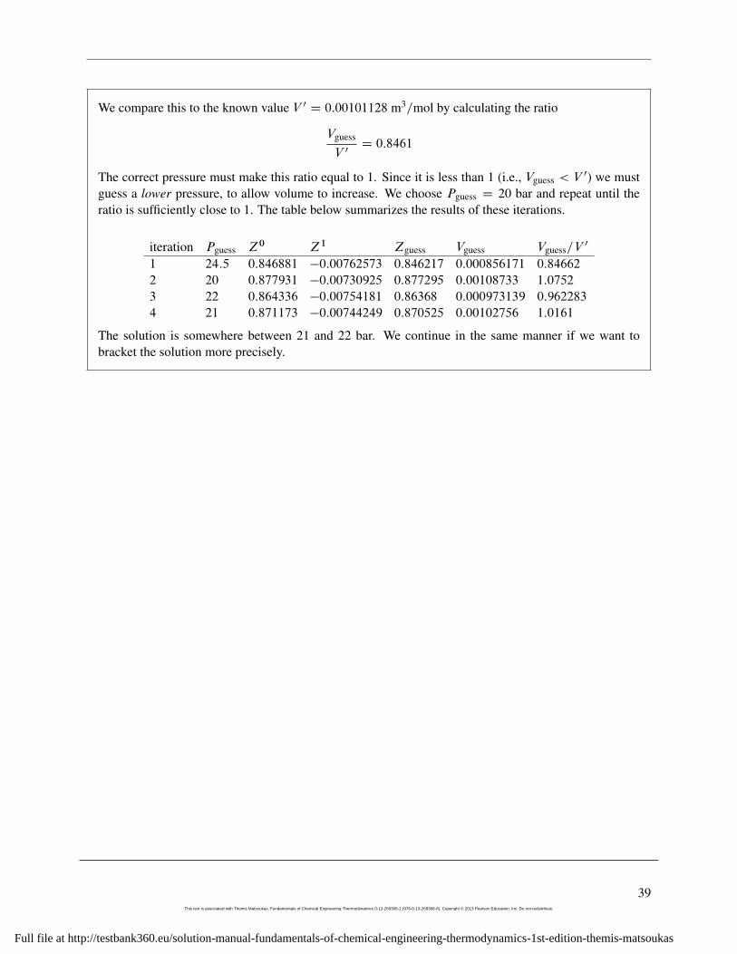
We compare this to the known value V 0 D 0:00101128 m3=mol by calculating the ratio
Vguess
V 0D 0:8461
The correct pressure must make this ratio equal to 1. Since it is less than 1 (i.e., Vguess < V 0) we mustguess a lower pressure, to allow volume to increase. We choose Pguess D 20 bar and repeat until theratio is sufficiently close to 1. The table below summarizes the results of these iterations.
iteration Pguess Z0 Z1 Zguess Vguess Vguess=V0
1 24:5 0:846881 �0:00762573 0:846217 0:000856171 0:84662
2 20 0:877931 �0:00730925 0:877295 0:00108733 1:0752
3 22 0:864336 �0:00754181 0:86368 0:000973139 0:962283
4 21 0:871173 �0:00744249 0:870525 0:00102756 1:0161
The solution is somewhere between 21 and 22 bar. We continue in the same manner if we want tobracket the solution more precisely.
39This text is associated with Themis Matsoukas, Fundamentals of Chemical Engineering Thermodynamics 0-13-269306-2 (978-0-13-269306-6). Copyright © 2013 Pearson Education, Inc. Do not redistribute.
Full file at http://testbank360.eu/solution-manual-fundamentals-of-chemical-engineering-thermodynamics-1st-edition-themis-matsoukas
2. PHASE DIAGRAMS OF PURE FLUIDS
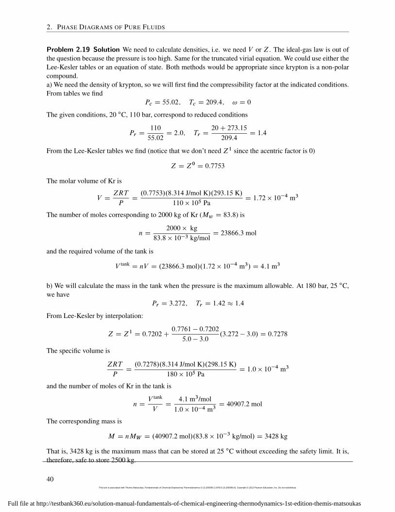
Problem 2.19 Solution We need to calculate densities, i.e. we need V or Z. The ideal-gas law is out ofthe question because the pressure is too high. Same for the truncated virial equation. We could use either theLee-Kesler tables or an equation of state. Both methods would be appropriate since krypton is a non-polarcompound.a) We need the density of krypton, so we will first find the compressibility factor at the indicated conditions.From tables we find
Pc D 55:02; Tc D 209:4; ! D 0
The given conditions, 20 ıC, 110 bar, correspond to reduced conditions
Pr D110
55:02D 2:0; Tr D
20C 273:15
209:4D 1:4
From the Lee-Kesler tables we find (notice that we don’t need Z1 since the acentric factor is 0)
Z D Z0 D 0:7753
The molar volume of Kr is
V DZRT
PD.0:7753/.8:314 J/mol K/.293:15 K/
110 � 105 PaD 1:72 � 10�4 m3
The number of moles corresponding to 2000 kg of Kr (Mw D 83:8) is
n D2000 � kg
83:8 � 10�3 kg/molD 23866:3 mol
and the required volume of the tank is
V tankD nV D .23866:3 mol/.1:72 � 10�4 m3/ D 4:1 m3
b) We will calculate the mass in the tank when the pressure is the maximum allowable. At 180 bar, 25 ıC,we have
Pr D 3:272; Tr D 1:42 � 1:4
From Lee-Kesler by interpolation:
Z D Z1 D 0:7202C0:7761 � 0:7202
5:0 � 3:0.3:272 � 3:0/ D 0:7278
The specific volume is
ZRT
PD.0:7278/.8:314 J/mol K/.298:15 K/
180 � 105 PaD 1:0 � 10�4 m3
and the number of moles of Kr in the tank is
n DV tank
VD
4:1 m3/mol1:0 � 10�4 m3
D 40907:2 mol
The corresponding mass is
M D nMW D .40907:2 mol/.83:8 � 10�3 kg/mol/ D 3428 kg
That is, 3428 kg is the maximum mass that can be stored at 25 ıC without exceeding the safety limit. It is,therefore, safe to store 2500 kg.
40This text is associated with Themis Matsoukas, Fundamentals of Chemical Engineering Thermodynamics 0-13-269306-2 (978-0-13-269306-6). Copyright © 2013 Pearson Education, Inc. Do not redistribute.
Full file at http://testbank360.eu/solution-manual-fundamentals-of-chemical-engineering-thermodynamics-1st-edition-themis-matsoukas
Problem 2.20 We collect the following information for n-butane:
Pc D 37:96 bar; Tc D 425:1 K; ! D 0:2; Vc D 255 cm3/mol; Zc D 0:274
a) We need the molar volume of the liquid. Our options are: Lee-Kesler, and Rackett. We choose the Rackettequation because it is known to be fairly accurate while the accuracy of the Lee-Kesler is not very good inthe liquid side. Still, if you did the problem using L-K I will consider the solution correct.
V D .255 cm3/mol/.0:274/.1�293:15=425:1/0:2857
D 100:9 cm3/mol
The moles is
ML D107 cm3
100:9 cm3/molD 99:1 � 103 mol
Note: This problem could also be done using the Lee-Kesler. The solution requires more calculations andthe final result is very close to the above. This calculation is given at the end of this solution. b) For thevolume of the vapor we use Lee-Kesler. The required interpolation is shown below.
Tr D 0:7
Pr D 0:05 Pr D 0:0545 Pr D 0:1
Z0 0:9504 0.9455 0:8958
Z1 �0:0507 �0:0566 �0:1161
from which we obtain the compressibility factor:
Z D 0:9455C .0:2/.�0:0566/ D 0:9342
The molar volume is
V DZRT
PD.0:9342/.8:314/.293:15/
2:07 � 105D 1:1 � 10�2 m3/mol
The moles of the vapor are
MV D10 m3
1:1 � 10�2 m3/molD 909 mol
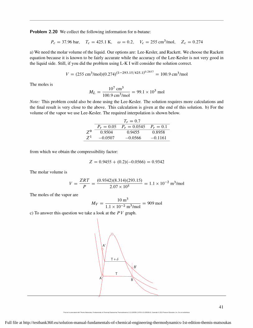
c) To answer this question we take a look at the PV graph.
A
A'
B
B'
T
T + d
41This text is associated with Themis Matsoukas, Fundamentals of Chemical Engineering Thermodynamics 0-13-269306-2 (978-0-13-269306-6). Copyright © 2013 Pearson Education, Inc. Do not redistribute.
Full file at http://testbank360.eu/solution-manual-fundamentals-of-chemical-engineering-thermodynamics-1st-edition-themis-matsoukas
2. PHASE DIAGRAMS OF PURE FLUIDS
Both sides of the tank undergo constant-volume processes as indicated by the dashed lines. The graphshows the two states at the initial temperature T , as well as the states at some higher temperature, T C ı.It is obvious that the pressure in the liquid side will always be higher than the pressure of the vapor side.Therefore, the pressure of 40 bar will be reached first in the liquid side, causing that alarm to go off.
d) To calculate the temperature at the state we recall that for liquids with constant ˇ and �, we have
lnV2
V1D ˇ�T � ��P
SInce volume is constant, V1 D V2 and solving for �T we find
�T D��P
ˇD3:4 � 10�4 bar�1.40 � 2:07/ bar
2:54 � 10�3 K�1D 5 ıC
The alarm will sound at T D 20C 5 D 25 ıC. At that point the pressure of the liquid side will be 40 barwhile that of the vapor will be not much higher than 2 bar!
Calculation of liquid V using Lee-Kesler:
If you opted to do the calculation using the Lee-Kesler tables, the correct solution is shown below. First wecalculate the reduced temperature and pressure.
Tr D 0:69 � 0:7; Pr D 0:545
Note: because the phase is liquid, one must extrapolate to Pr D 0:0545 from the listed values for the liquid(shown in the tables in italics):
Tr D 0:7
Pr D 0:0545 Pr D 0:2 Pr D 0:4
Z0 9:45 � 1�3 0:0344 0:0687
Z1 �4:1785 � 10�3 �0:0148 �0:0294
With these values we obtain the following:
Z D .9:45 � 1�3/C .0:2/.�4:1785 � 10�3/ D 8:614 � 10�3
V DZRT
PD.8:614 � 10�3/.8:314 J/mol K/.293:15 K/
2:07 � 105 PaD 1:01 � 10�4 m3/mol
ML D10 m3
1:01 � 10�4 m3/molD 98:5 � 103 mol
The answer is very close to that obtained using the Rackett equation but the Lee-Kesler method requires morecalculations.
42This text is associated with Themis Matsoukas, Fundamentals of Chemical Engineering Thermodynamics 0-13-269306-2 (978-0-13-269306-6). Copyright © 2013 Pearson Education, Inc. Do not redistribute.
Full file at http://testbank360.eu/solution-manual-fundamentals-of-chemical-engineering-thermodynamics-1st-edition-themis-matsoukas
Problem 2.21 Solution Solution a) Filled with xenonWe need the volume of the tank which will obtain by first calculating the molar volume of xenon. We willdo this calculation using the Pitzer method and the Lee Kesler tables. For xenon:
Tc D 289:7 KIPc D 58:4 barI! D 0IMw D 131:30 g/mol
The reduced temperature and pressure are
Tr D132C 273:15
289:7D 1:39852 � 1:4; Pr D
82
58:4D 1:4:
Interpolating at Tr D 1:4 between Pr = 1.2 and Pr = 1.5 we find
Z0 D 0:836436
Since ! D 0, Z D Z0 D 0:836436. Using SI units, the molar volume of xenon is
V DZRT
PD .0:836436/.8:314/.405:15/82 � 105 D 3:436 � 104 m3 /mol
Since the tank contains 10,000 kg, or
n D10; 000 kg
131:30 � 10�3 kg molD 76; 161 mol
the volume of the tank isV t D nV D 26:16 m3
Filled with steam The specific volume of steam in the tank is
V D26:16 m3
10000 kgD 2:616 cm3/g
At 200 ıC, the saturated volumes of water are 1.156 and 127.2 cm3 /g. Since the specific volume lies be-tween the two values, the steam is a saturated vapor/liquid mixture and the pressure is equal to the saturationpressure at 200 ıC: P D 15:45 bar.
b) If the mass in the tank is reduced to half, the specific volume doubles:
V D .2/.2:616/ D 5:232 cm3/g
This value is still between that of the saturated vapor and liquid, therefore the pressure remains constant.
43This text is associated with Themis Matsoukas, Fundamentals of Chemical Engineering Thermodynamics 0-13-269306-2 (978-0-13-269306-6). Copyright © 2013 Pearson Education, Inc. Do not redistribute.
Full file at http://testbank360.eu/solution-manual-fundamentals-of-chemical-engineering-thermodynamics-1st-edition-themis-matsoukas
2. PHASE DIAGRAMS OF PURE FLUIDS
Problem 2.22 Solution a) Vapor.
b) At 0.1 bar, 200 C, o-xylene is essentially in the ideal-gas state (why?).
V DRT
PD 0:393377 m3=mol
The volume of the tank is
V tankD .200 mol/.0:393377 m3=mol/ D 39:3 m3: (2.2)
c) At 44.9 bar, 200 C, the reduced temperature an pressure is
Tr D 0:75; Pr D 1:2
From the Lee-Kesler tables we find
Z0 D 0:84435; Z1 D 0:0453;Z D 0:8585
The molar volume isV2 D
ZRT
P2D 0:000752133 m3=mol
and the number of moles
n DV tank
V2D 52301:5 mol
44This text is associated with Themis Matsoukas, Fundamentals of Chemical Engineering Thermodynamics 0-13-269306-2 (978-0-13-269306-6). Copyright © 2013 Pearson Education, Inc. Do not redistribute.
Full file at http://testbank360.eu/solution-manual-fundamentals-of-chemical-engineering-thermodynamics-1st-edition-themis-matsoukas
Problem 2.23 Solution a) We first calculate the coefficient of thermal expansion form the empirical equa-tion given above:
ˇ D1
V
�@V
@t
�P
�@t
@T
�where t stands for temperature in celsius and T for temperature in kelvin. Using the polynomial expressiongiven in the problem statement we find
ˇ Da1 C 2a2t C 3a3t
2
1C a1t C a2t2 C a3t3
For constant pressure process,
dV
VD ˇdT )
V2
V1D eˇ.T2�T1/
For this calculation we will use an average value of ˇ between 18 ıC and 40 ıC:
ˇav D 0:5.ˇ18 C ˇ40/ D 0:5.7:09 � 10�4C 7:27 � 10�4/ K�1
D 7:18 � 10�4 K�1
With this value, the change in volume isV2
V1D 1:016
or an increase of 1/6%.
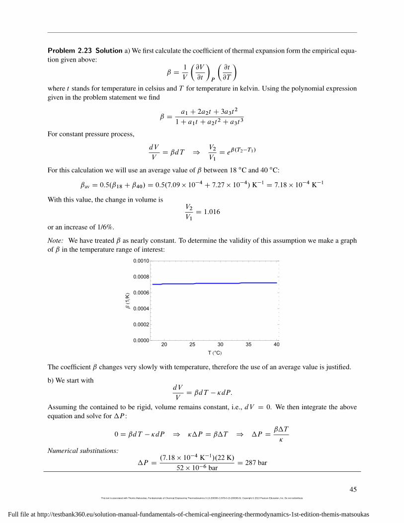
Note: We have treated ˇ as nearly constant. To determine the validity of this assumption we make a graphof ˇ in the temperature range of interest:
20 25 30 35 400.0000
0.0002
0.0004
0.0006
0.0008
0.0010
T H°CL
ΒH1
�KL
The coefficient ˇ changes very slowly with temperature, therefore the use of an average value is justified.
b) We start withdV
VD ˇdT � �dP:
Assuming the contained to be rigid, volume remains constant, i.e., dV D 0. We then integrate the aboveequation and solve for �P :
0 D ˇdT � �dP ) ��P D ˇ�T ) �P Dˇ�T
�
Numerical substitutions:
�P D.7:18 � 10�4 K�1/.22 K/
52 � 10�6 barD 287 bar
45This text is associated with Themis Matsoukas, Fundamentals of Chemical Engineering Thermodynamics 0-13-269306-2 (978-0-13-269306-6). Copyright © 2013 Pearson Education, Inc. Do not redistribute.
Full file at http://testbank360.eu/solution-manual-fundamentals-of-chemical-engineering-thermodynamics-1st-edition-themis-matsoukas
2. PHASE DIAGRAMS OF PURE FLUIDS
Problem 2.24 Solution The numerical results are summarized in the atatched tables:
46This text is associated with Themis Matsoukas, Fundamentals of Chemical Engineering Thermodynamics 0-13-269306-2 (978-0-13-269306-6). Copyright © 2013 Pearson Education, Inc. Do not redistribute.
Full file at http://testbank360.eu/solution-manual-fundamentals-of-chemical-engineering-thermodynamics-1st-edition-themis-matsoukas
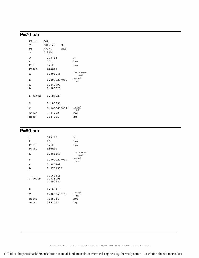
P=70 barFluid CO2Tc 304.129 KPc 73.74 barw 0.225
T 293.15 KP 70. barPsat 57.2 barPhase Liquid
a 0.381864 Joule Meter3
Mol2
b 0.0000297087 Meter3
Mol
A 0.449994B 0.085326
Z roots 0.186938
Z 0.186938
V 0.0000650879 Meter3
Mol
moles 7681.92 Molmass 338.081 kg
P=60 barT 293.15 KP 60. barPsat 57.2 barPhase Liquid
a 0.381864 Joule Meter3
Mol2
b 0.0000297087 Meter3
Mol
A 0.385709B 0.0731366
Z roots0.1694180.3380980.492484
Z 0.169418
V 0.000068819 Meter3
Mol
moles 7265.44 Molmass 319.752 kg
This text is associated with Themis Matsoukas, Fundamentals of Chemical Engineering Thermodynamics 0-13-269306-2 (978-0-13-269306-6). Copyright © 2013 Pearson Education, Inc. Do not redistribute.
Full file at http://testbank360.eu/solution-manual-fundamentals-of-chemical-engineering-thermodynamics-1st-edition-themis-matsoukas
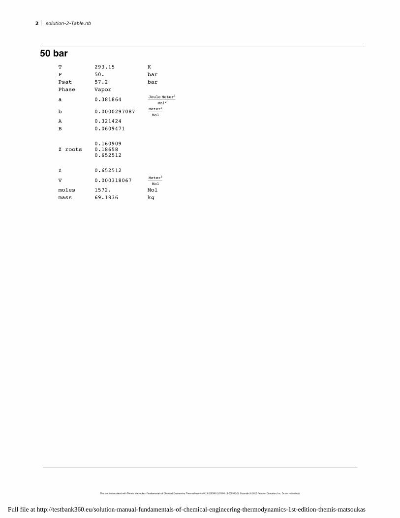
50 barT 293.15 KP 50. barPsat 57.2 barPhase Vapor
a 0.381864 Joule Meter3
Mol2
b 0.0000297087 Meter3
Mol
A 0.321424B 0.0609471
Z roots0.1609090.186580.652512
Z 0.652512
V 0.000318067 Meter3
Mol
moles 1572. Molmass 69.1836 kg
2 solution-2-Table.nb
This text is associated with Themis Matsoukas, Fundamentals of Chemical Engineering Thermodynamics 0-13-269306-2 (978-0-13-269306-6). Copyright © 2013 Pearson Education, Inc. Do not redistribute.
Full file at http://testbank360.eu/solution-manual-fundamentals-of-chemical-engineering-thermodynamics-1st-edition-themis-matsoukas
Problem 2.25 Solution
First we collect the parameters for isobutane:
Tc D 408:1 K; Pc D 36:48 bar; ! D 0:181; Mw D 58:123 � 10�3 kg/mol
We are given T D 294:26 K, P D 4:13793 bar. With this information we find that the compressibilityequation has three real roots:
Z1 D 0:0185567; Z2 D 0:100577; Z3 D 0:880866;
We know that the phase is liquid (since the given temperature is below the saturation temperature at thegiven pressure), therefore the correct compressibility factor is the smallest of the three:
Z D 0:0185567
The corresponding molar volume is
V D ZRT
PD .0:0185567/
.8:314 J/mol K/.294:26 K/4:13793 � 105 Pa
D 1:09713 � 10�4 m3/mol
The amount (moles) of isobutane is
n D5000 kg
58:123 � 10�3 kg/molD 86024:5 mol
Therefore, the volume of the tank is
V tank D .86024:5 mol/.1:09713 � 10�4 m3/mol/ D 9:44 m3
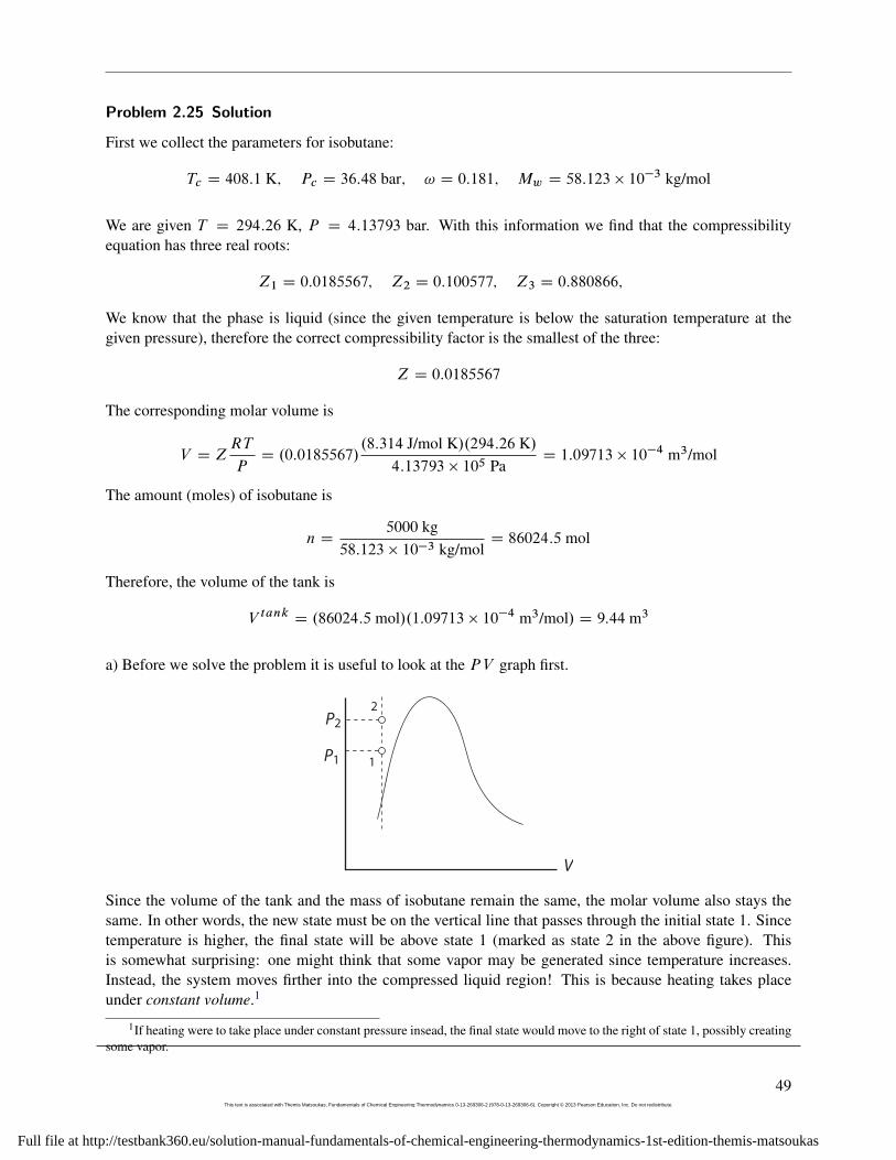
a) Before we solve the problem it is useful to look at the PV graph first.
P1
P2
V
1
2
Since the volume of the tank and the mass of isobutane remain the same, the molar volume also stays thesame. In other words, the new state must be on the vertical line that passes through the initial state 1. Sincetemperature is higher, the final state will be above state 1 (marked as state 2 in the above figure). Thisis somewhat surprising: one might think that some vapor may be generated since temperature increases.Instead, the system moves firther into the compressed liquid region! This is because heating takes placeunder constant volume.1
1If heating were to take place under constant pressure insead, the final state would move to the right of state 1, possibly creatingsome vapor.
49This text is associated with Themis Matsoukas, Fundamentals of Chemical Engineering Thermodynamics 0-13-269306-2 (978-0-13-269306-6). Copyright © 2013 Pearson Education, Inc. Do not redistribute.
Full file at http://testbank360.eu/solution-manual-fundamentals-of-chemical-engineering-thermodynamics-1st-edition-themis-matsoukas
2. PHASE DIAGRAMS OF PURE FLUIDS
b) Since the total volume and mass in the tank remain the same, the molar volume must also stay the same,namely,
V D 1:09713 � 10�4 m3/mol
The pressure can now be calculated directly from the SRK equation:
P DRT
V � b�
a
V.V C b/
Notice, however, that the parameter a must be recalculated because it depends on temperature. With T D308:15 K we find
a D 1:68988 J m3/mol2
Using this value of a, the previous value of b, and V D 1:09713 � 10�4 m3/mol, the SRK equation gives
P D 70:1 bar
This represents an increase of 66 bar even though temperature increased only by 20 ıF! The reason is thatisotherms in the compressed liquid state are very steep, resulting in large pressure change under constant-volume heating.
50This text is associated with Themis Matsoukas, Fundamentals of Chemical Engineering Thermodynamics 0-13-269306-2 (978-0-13-269306-6). Copyright © 2013 Pearson Education, Inc. Do not redistribute.
Full file at http://testbank360.eu/solution-manual-fundamentals-of-chemical-engineering-thermodynamics-1st-edition-themis-matsoukas
Problem 2.26 Solution
a) At 30 ıC, 1 bar the SRK equation has the following three real roots. Since the phase is vapor (why?) wepick the largest root:
Z D 0:977286 V DZRT
PD 0:0246314 m3=mol
b) At 30 ıC, 10 bar the SRK equation has the following three real roots. The phase is liquid (why?), thereforewe pick the smallest root:
Z D 0:0413973 V DZRT
PD 0:000104337 m3=mol
b) At 30 ıC, 4.05 bar the SRK equation has the following three real roots. Since the system is saturated, thesmallest root is the liquid and largest is the vapor:
ZL D 0:0413973; VL DZLRT
P sat D 0:000104698 m3=mol
ZV D 0:901582; VV DZVRT
P sat D 0:00561071 m3=mol
The literature values from the NIST Web Book are
VL D 0:00010678 m3=mol VV D 0:0055461 m3=mol
The SRK values are off by �2% (liquid) and 1:2% (vapor). These errors are pretty small.
51This text is associated with Themis Matsoukas, Fundamentals of Chemical Engineering Thermodynamics 0-13-269306-2 (978-0-13-269306-6). Copyright © 2013 Pearson Education, Inc. Do not redistribute.
Full file at http://testbank360.eu/solution-manual-fundamentals-of-chemical-engineering-thermodynamics-1st-edition-themis-matsoukas
2. PHASE DIAGRAMS OF PURE FLUIDS
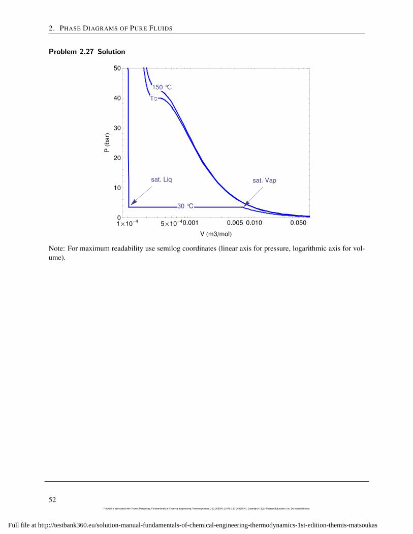
Problem 2.27 Solution
150 °C150 °C
30 °C
sat. Liq sat. Vap
TcTcT
c
T
c
1´10-4 5´10-40.001 0.005 0.010 0.0500
10
20
30
40
50
V Hm3�molL
PHb
arL
Note: For maximum readability use semilog coordinates (linear axis for pressure, logarithmic axis for vol-ume).
52This text is associated with Themis Matsoukas, Fundamentals of Chemical Engineering Thermodynamics 0-13-269306-2 (978-0-13-269306-6). Copyright © 2013 Pearson Education, Inc. Do not redistribute.
Full file at http://testbank360.eu/solution-manual-fundamentals-of-chemical-engineering-thermodynamics-1st-edition-themis-matsoukas
Problem 2.28 Solution The the general form for the differential of V is
dV
VD ˇdT � �dP
Using the given expressions for ˇ and � we have
d lnV DdT
T�dP
PŒA�
Integration is this differential from V0, T0, P0 to V , T , P is very simple in this case because the variableshappen to be separated (each of the three terms contains one variable only). The result is
lnV
V0D ln
T
T0� ln
P
P0ŒB�
The same result is obtained if we adopt an arbitrary integration path, say from T0, P0, under constant T toT0, P , and then under constant P to T , P . As we can easily verify, the differential of the above is indeedequal to Eq. [A]. Equation [B] can be rearranged to write
lnV
V0D ln
�T
T0�P0
P
�or
PV
TDP0V0
T0
In other words we have obtained the ideal-gas law.
Based on the final result we can certainly say that this equation of state is not appropriate for liquids. Evenbefore integration, however, we could reach the same conclusion by looking at the T and P dependence ofˇ and �. The inverse dependence of ˇ on T (and of � on P ) indicates that these parameters vary quite a bitwith pressure and temperature. This is a characteristic of gases. The values of � and ˇ for solids and liquidsare typically small numbers and vary much less with temperature and pressure.
53This text is associated with Themis Matsoukas, Fundamentals of Chemical Engineering Thermodynamics 0-13-269306-2 (978-0-13-269306-6). Copyright © 2013 Pearson Education, Inc. Do not redistribute.
Full file at http://testbank360.eu/solution-manual-fundamentals-of-chemical-engineering-thermodynamics-1st-edition-themis-matsoukas
2. PHASE DIAGRAMS OF PURE FLUIDS
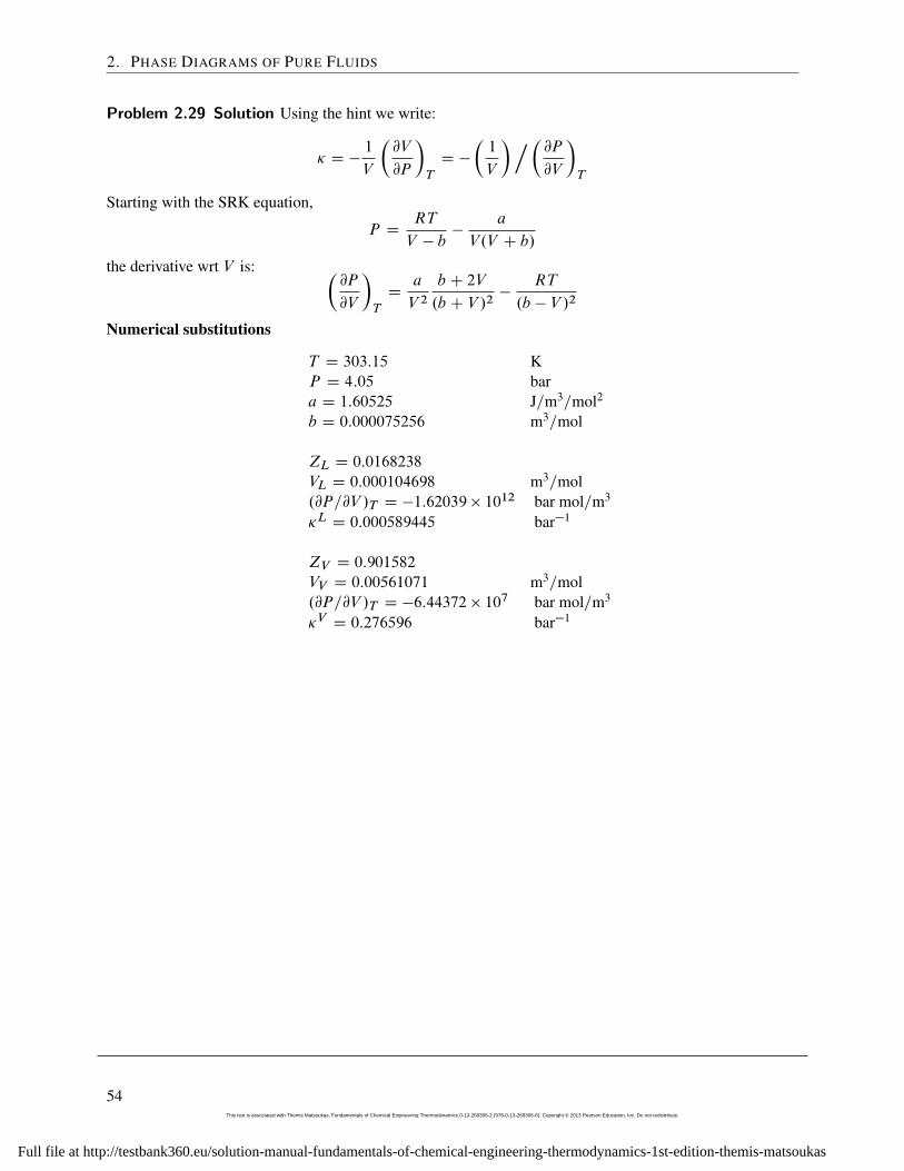
Problem 2.29 Solution Using the hint we write:
� D �1
V
�@V
@P
�T
D �
�1
V
�.�@P@V
�T
Starting with the SRK equation,
P DRT
V � b�
a
V.V C b/
the derivative wrt V is: �@P
@V
�T
Da
V 2b C 2V
.b C V /2�
RT
.b � V /2
Numerical substitutions
T D 303:15 KP D 4:05 bara D 1:60525 J=m3=mol2
b D 0:000075256 m3=mol
ZL D 0:0168238
VL D 0:000104698 m3=mol.@P=@V /T D �1:62039 � 10
12 bar mol=m3
�L D 0:000589445 bar�1
ZV D 0:901582
VV D 0:00561071 m3=mol.@P=@V /T D �6:44372 � 10
7 bar mol=m3
�V D 0:276596 bar�1
54This text is associated with Themis Matsoukas, Fundamentals of Chemical Engineering Thermodynamics 0-13-269306-2 (978-0-13-269306-6). Copyright © 2013 Pearson Education, Inc. Do not redistribute.
Full file at http://testbank360.eu/solution-manual-fundamentals-of-chemical-engineering-thermodynamics-1st-edition-themis-matsoukas
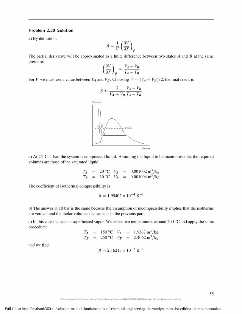
Problem 2.30 Solution
a) By definition,
ˇ D1
V
�@V
@T
�P
The partial derivative will be approximated as a finite difference between two states A and B at the samepressure: �
@V
@T
�P
�VA � VB
TA � TB
For V we must use a value between VA and VB . Choosing V D .VA C VB/=2, the final result is
ˇ �2
VA C VB
VA � VB
TA � TB
A B
C
D
const. P
Pressure
Volume
a) At 25ıC, 1 bar, the system is compressed liquid. Assuming the liquid to be incompressible, the requiredvolumes are those of the saturated liquid.
TA D 20 ıC VA D 0:001002 m3=kgTB D 30 ıC VB D 0:001004 m3=kg
The coefficient of isothermal compressibility is
ˇ D 1:99402 � 10�4 K�1
b) The answer at 10 bar is the same because the assumption of incompressibility implies that the isothermsare vertical and the molar volumes the same as in the previous part.
c) In this case the state is superheated vapor. We select two temperatures around 200 ıC and apply the sameprocedure:
TA D 150 ıC VA D 1:9367 m3=kgTB D 250 ıC VB D 2:4062 m3=kg
and we findˇ D 2:16215 � 10�3 K�1
55This text is associated with Themis Matsoukas, Fundamentals of Chemical Engineering Thermodynamics 0-13-269306-2 (978-0-13-269306-6). Copyright © 2013 Pearson Education, Inc. Do not redistribute.
Full file at http://testbank360.eu/solution-manual-fundamentals-of-chemical-engineering-thermodynamics-1st-edition-themis-matsoukas
2. PHASE DIAGRAMS OF PURE FLUIDS
Problem 2.31 Solution Solution
Assuming isotherms in the compressed liquid region to be vertical, ˇ is calculated as
ˇ D1
V
�@V
@T
�P
D1
V1CV2
2
V2 � V1
T2 � T1
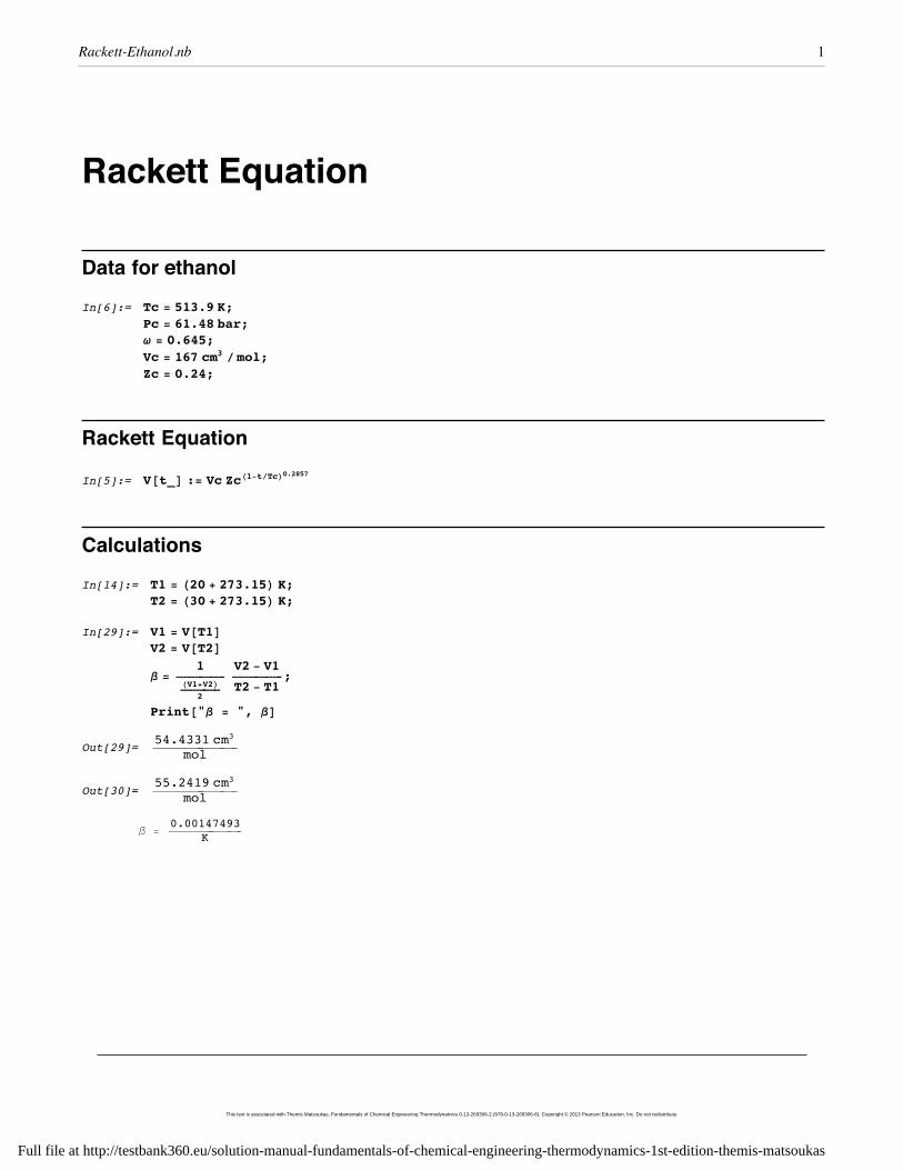
where T1, T2 are two temperatures around 24 ıC, and V1, V2, are the volumes of the saturated liquid at thesetemperatures, to be calculated using the Rackett equation. With T1 D 20ıC, T2 D 30 ıC we find
ˇ D 1:475 � 10�3 K�1
Calculation are shown in the attached notebook.
56This text is associated with Themis Matsoukas, Fundamentals of Chemical Engineering Thermodynamics 0-13-269306-2 (978-0-13-269306-6). Copyright © 2013 Pearson Education, Inc. Do not redistribute.
Full file at http://testbank360.eu/solution-manual-fundamentals-of-chemical-engineering-thermodynamics-1st-edition-themis-matsoukas
Rackett Equation
Data for ethanolIn[6]:= Tc = 513.9 K;
Pc = 61.48 bar;w = 0.645;Vc = 167 cm3 ê mol;Zc = 0.24;
Rackett Equation
In[5]:= V@t_D := Vc ZcH1-têTcL0.2857
CalculationsIn[14]:= T1 = H20 + 273.15L K;
T2 = H30 + 273.15L K;
In[29]:= V1 = V@T1DV2 = V@T2Db =
1ÅÅÅÅÅÅÅÅÅÅÅÅÅÅÅÅÅHV1+V2LÅÅÅÅÅÅÅÅÅÅÅÅÅÅ
2
V2 - V1ÅÅÅÅÅÅÅÅÅÅÅÅÅÅÅÅÅÅT2 - T1
;
Print@"b = ", bDOut[29]= 54.4331 cm3
ÅÅÅÅÅÅÅÅÅÅÅÅÅÅÅÅÅÅÅÅÅÅÅÅÅÅÅÅÅÅmol
Out[30]=55.2419 cm3ÅÅÅÅÅÅÅÅÅÅÅÅÅÅÅÅÅÅÅÅÅÅÅÅÅÅÅÅÅÅmol
b =0.00147493ÅÅÅÅÅÅÅÅÅÅÅÅÅÅÅÅÅÅÅÅÅÅÅÅÅÅÅÅÅÅK
Rackett-Ethanol.nb 1
This text is associated with Themis Matsoukas, Fundamentals of Chemical Engineering Thermodynamics 0-13-269306-2 (978-0-13-269306-6). Copyright © 2013 Pearson Education, Inc. Do not redistribute.
Full file at http://testbank360.eu/solution-manual-fundamentals-of-chemical-engineering-thermodynamics-1st-edition-themis-matsoukas
Recommended