The Series RHP Humidity and Temperature Transmitter offers flexibility, high
accuracy, long term stability, and reliable operation. Utilizing the duct and outside
air mounting configurations, the Series RHP monitors and controls humidity or
both humidity and temperature in a building energy management systems,
commercial and residential HVAC applications, clean rooms, museums, and
climate chambers.
The state of the art sensor technology allows the Series RHP to fully recover from
100% saturation and is calibration-free. The removable filter and field replaceable
sensor allows for quick service and reduced inventory of complete units. The metal
mounting flange on the duct mount models reduces the time to attach the
transmitter to the duct.
The Series RHP can be ordered with at single current or voltage output for
humidity or can be factory configured to have an additional current, voltage, or
passive RTD or thermistor temperature output. The RTD and thermistor outputs
are interchangeable in the field without any additional calibration. The optional
display for the duct mount models allows the user to read both the temperature
and humidity simultaneously.
Series RHP Temperature/Humidity Transmitter
Specifications - Installation and Operating Instructions
Bulletin E-90-RHP
DWYER INSTRUMENTS, INC. Phone: 219/879-8000 www.dwyer-inst.com
P.O. BOX 373 • MICHIGAN CITY, INDIANA 46360, U.S.A. Fax: 219/872-9057 e-mail: [email protected]
SPECIFICATIONS
Relative Humidity Range: 0 to 100%
RH.
Temperature Range: -40 to 140°F
(-40 to 60°C).
Accuracy, RH:
Model RHP2 ±2% 10-90% RH @
25°C; Model RHP3 ±3% 20-80% RH
@ 25°C.
Accuracy, Thermistor Temp Sensor:
±0.22°C @ 25°C (±0.4°F @ 77°F).
Accuracy, RTD Temp Sensor: DIN
Class B; ±0.3°C @ 0°C (±0.54°F @
32°F).
Accuracy, Solid State Temperature
Sensor: ±0.9°F @72°F (±0.3°C @
25°C)
Hysteresis: ±1%.
Repeatability: ±0.1% typical.
Temperature Limits: -40 to 140°F
(-40 to 60°C).
Storage Temperature: -40 to 176°F
(-40 to 80°C).
Compensated Temperature Range: -
4 to 140°F (-20 to 60°C).
4-20 mA Loop Powered Models:
Power Requirements: 10-35
VDC.
Output Signal: 4-20 mA, 2
channels for humidity/solid state
temperature, sensor models (loop
powered on RH).
0-5, 0-10V Output Models:
Power Requirements: 15-35
VDC or 15-29 VAC.
Output Signal: 0-5, 0-10V @ 5 mA
max, 2 channels for humidity/solid
state temperature sensor models.
Response Time: 15 seconds.
Electrical Connections:
Removable screw terminal block.
Conduit Connection: Duct
mount: 1/2˝ NPS; OSA: 1/2˝ (22.3 mm).
Drift: <1% RH/year.
RH Sensor: Capacitance polymer.
Temperature Sensor:
Curves A,B,C, F: Thermistor;
Curves D,E: Platinum RTD DIN 385;
Curve 0: None.
Curve 1,2: Solid state band gap.
Housing Material: Duct Mount: PBT;
OSA: Polycarbonate.
Enclosure Rating: NEMA 4X (IP65)
for OSA mount only.
Display: Duct Mount only, Optional 2-
line alpha numeric, 8 characters/line.
Display Resolution: RH: 0.1%; 0.1°F
(0.1°C).
Weight: Duct Mount .616 (.3 kg) OSA
1 lb (.45 kg).
Agency Approvals: CE.
2- 9/16[64.96]
(3) 3/16 (4.76) HOLESEQUALLY SPACED ON A
4 115 (104.52) BC
ø35/64[ø13.89]
9[228.60]
2-33/64[63.90]
1/2 NPT
2-11/64[55.17]
2-9/64[54.37]
ø3-7/16[ø87.31]
ø3-11/64[ø80.57]
2-11/64[55.12]
6-25/32[172.09]
5-1/8[130.18]4-17/32
[115.09]2-15/64[56.75]
3-1/8[79.38]
4-17/32[115.09]
Ø3/16[4.76]
MOUNTINGHOLES
TYP 4 PLCS
3-1/8[79.38]
1-13/64[30.56]
55/64[21.83]
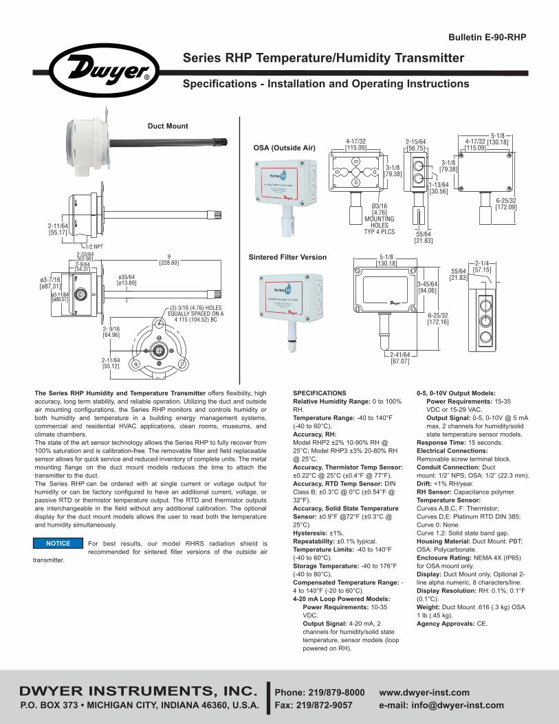
OSA (Outside Air)
Sintered Filter Version2-1/4
[57.15]55/64[21.83]
6-25/32[172.16]
3-45/64[94.06]
2-41/64[67.07]
5-1/8[130.18]
Duct Mount
For best results, our model RHRS radiation shield is
recommended for sintered filter versions of the outside air
transmitter.
NOTICE
E-90-RHP_E-90-RH 8/21/12 10:12 AM Page 1
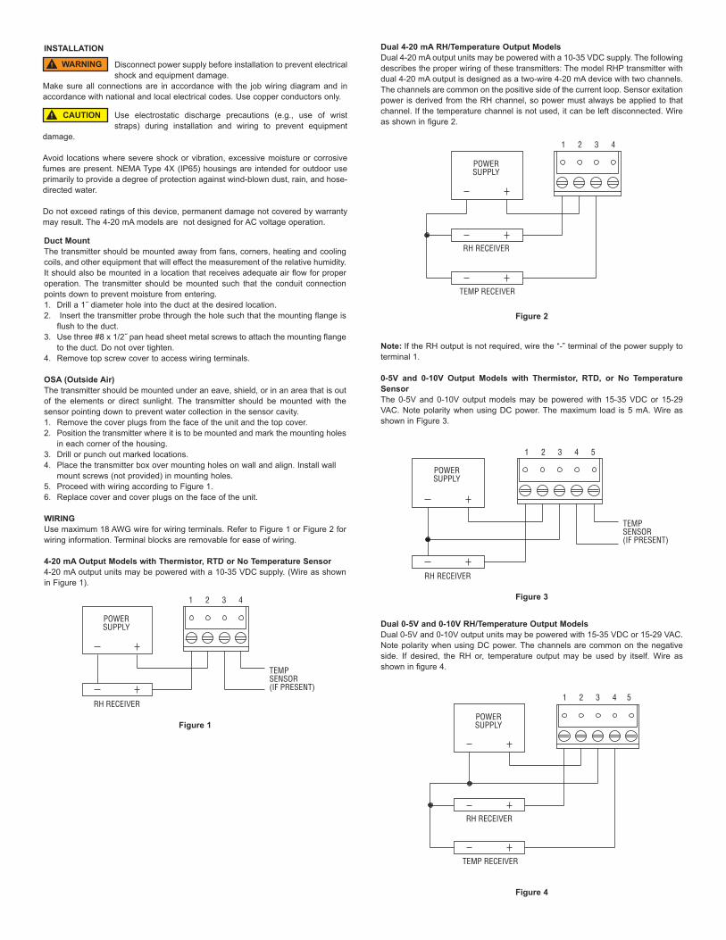
Dual 4-20 mA RH/Temperature Output Models
Dual 4-20 mA output units may be powered with a 10-35 VDC supply. The following
describes the proper wiring of these transmitters: The model RHP transmitter with
dual 4-20 mA output is designed as a two-wire 4-20 mA device with two channels.
The channels are common on the positive side of the current loop. Sensor exitation
power is derived from the RH channel, so power must always be applied to that
channel. If the temperature channel is not used, it can be left disconnected. Wire
as shown in figure 2.
Note: If the RH output is not required, wire the “-” terminal of the power supply to
terminal 1.
0-5V and 0-10V Output Models with Thermistor, RTD, or No Temperature
Sensor
The 0-5V and 0-10V output models may be powered with 15-35 VDC or 15-29
VAC. Note polarity when using DC power. The maximum load is 5 mA. Wire as
shown in Figure 3.
Dual 0-5V and 0-10V RH/Temperature Output Models
Dual 0-5V and 0-10V output units may be powered with 15-35 VDC or 15-29 VAC.
Note polarity when using DC power. The channels are common on the negative
side. If desired, the RH or, temperature output may be used by itself. Wire as
shown in figure 4.
INSTALLATION
Duct Mount
The transmitter should be mounted away from fans, corners, heating and cooling
coils, and other equipment that will effect the measurement of the relative humidity.
It should also be mounted in a location that receives adequate air flow for proper
operation. The transmitter should be mounted such that the conduit connection
points down to prevent moisture from entering.
1. Drill a 1˝ diameter hole into the duct at the desired location.
2. Insert the transmitter probe through the hole such that the mounting flange is
flush to the duct.
3. Use three #8 x 1/2˝ pan head sheet metal screws to attach the mounting flange
to the duct. Do not over tighten.
4. Remove top screw cover to access wiring terminals.
OSA (Outside Air)
The transmitter should be mounted under an eave, shield, or in an area that is out
of the elements or direct sunlight. The transmitter should be mounted with the
sensor pointing down to prevent water collection in the sensor cavity.
1. Remove the cover plugs from the face of the unit and the top cover.
2. Position the transmitter where it is to be mounted and mark the mounting holes
in each corner of the housing.
3. Drill or punch out marked locations.
4. Place the transmitter box over mounting holes on wall and align. Install wall
mount screws (not provided) in mounting holes.
5. Proceed with wiring according to Figure 1.
6. Replace cover and cover plugs on the face of the unit.
WIRING
Use maximum 18 AWG wire for wiring terminals. Refer to Figure 1 or Figure 2 for
wiring information. Terminal blocks are removable for ease of wiring.
4-20 mA Output Models with Thermistor, RTD or No Temperature Sensor
4-20 mA output units may be powered with a 10-35 VDC supply. (Wire as shown
in Figure 1).
Figure 1
Figure 3
POWERSUPPLY
TEMPSENSOR(IF PRESENT)
RH RECEIVER
1 2 3 4
POWERSUPPLY
RH RECEIVER
TEMP RECEIVER
1 2 3 4
Figure 2
POWERSUPPLY
RH RECEIVER
TEMPSENSOR(IF PRESENT)
1 2 3 4 5
POWERSUPPLY
RH RECEIVER
TEMP RECEIVER
1 2 3 4 5
Figure 4
Disconnect power supply before installation to prevent electrical
shock and equipment damage.
Make sure all connections are in accordance with the job wiring diagram and in
accordance with national and local electrical codes. Use copper conductors only.
WARNING
Use electrostatic discharge precautions (e.g., use of wrist
straps) during installation and wiring to prevent equipment
damage.
Avoid locations where severe shock or vibration, excessive moisture or corrosive
fumes are present. NEMA Type 4X (IP65) housings are intended for outdoor use
primarily to provide a degree of protection against wind-blown dust, rain, and hose-
directed water.
Do not exceed ratings of this device, permanent damage not covered by warranty
may result. The 4-20 mA models are not designed for AC voltage operation.
CAUTION
E-90-RHP_E-90-RH 8/21/12 10:12 AM Page 2
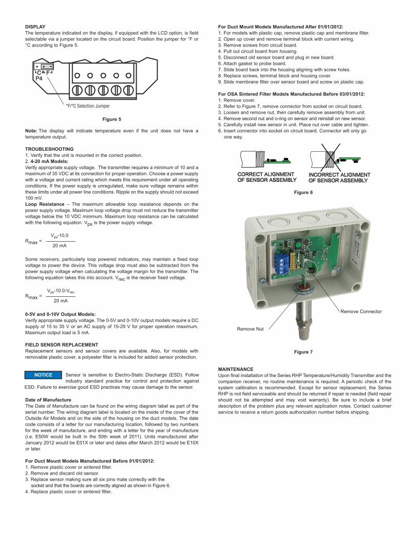
DISPLAY
The temperature indicated on the display, if equipped with the LCD option, is field
selectable via a jumper located on the circuit board. Position the jumper for °F or
°C according to Figure 5.
Note: The display will indicate temperature even if the unit does not have a
temperature output.
TROUBLESHOOTING
1. Verify that the unit is mounted in the correct position.
2. 4-20 mA Models:
Verify appropriate supply voltage. The transmitter requires a minimum of 10 and a
maximum of 35 VDC at its connection for proper operation. Choose a power supply
with a voltage and current rating which meets this requirement under all operating
conditions. If the power supply is unregulated, make sure voltage remains within
these limits under all power line conditions. Ripple on the supply should not exceed
100 mV.
Loop Resistance – The maximum allowable loop resistance depends on the
power supply voltage. Maximum loop voltage drop must not reduce the transmitter
voltage below the 10 VDC minimum. Maximum loop resistance can be calculated
with the following equation. Vps is the power supply voltage.
Rmax =
Some receivers, particularly loop powered indicators, may maintain a fixed loop
voltage to power the device. This voltage drop must also be subtracted from the
power supply voltage when calculating the voltage margin for the transmitter. The
following equation takes this into account. Vrec is the receiver fixed voltage.
Rmax =
0-5V and 0-10V Output Models:
Verify appropriate supply voltage. The 0-5V and 0-10V output models require a DC
supply of 15 to 35 V or an AC supply of 15-29 V for proper operation maximum.
Maximum output load is 5 mA.
FIELD SENSOR REPLACEMENT
Replacement sensors and sensor covers are available. Also, for models with
removable plastic cover, a polyester filter is included for added sensor protection.
Date of Manufacture
The Date of Manufacture can be found on the wiring diagram label as part of the
serial number. The wiring diagram label is located on the inside of the cover of the
Outside Air Models and on the side of the housing on the duct models. The date
code consists of a letter for our manufacturing location, followed by two numbers
for the week of manufacture, and ending with a letter for the year of manufacture
(i.e. E50W would be built in the 50th week of 2011). Units manufactured after
January 2012 would be E01X or later and dates after March 2012 would be E10X
or later.
For Duct Mount Models Manufactured Before 01/01/2012:
1. Remove plastic cover or sintered filter.
2. Remove and discard old sensor.
3. Replace sensor making sure all six pins mate correctly with the
socket and that the boards are correctly aligned as shown in Figure 6.
4. Replace plastic cover or sintered filter.
For Duct Mount Models Manufactured After 01/01/2012:
1. For models with plastic cap, remove plastic cap and membrane filter.
2. Open up cover and remove terminal block with current wiring.
3. Remove screws from circuit board.
4. Pull out circuit board from housing.
5. Disconnect old sensor board and plug in new board.
6. Attach gasket to probe board.
7. Slide board back into the housing aligning with screw holes.
8. Replace screws, terminal block and housing cover.
9. Slide membrane filter over sensor board and screw on plastic cap.
For OSA Sintered Filter Models Manufactured Before 03/01/2012:
1. Remove cover.
2. Refer to Figure 7, remove connector from socket on circuit board.
3. Loosen and remove nut, then carefully remove assembly from unit.
4. Remove second nut and o-ring on sensor and reinstall on new sensor.
5. Carefully install new sensor in unit. Place nut over cable and tighten.
6. Insert connector into socket on circuit board. Connector will only go
one way.
MAINTENANCE
Upon final installation of the Series RHP Temperature/Humidity Transmitter and the
companion receiver, no routine maintenance is required. A periodic check of the
system calibration is recommended. Except for sensor replacement, t he Series
RHP is not field serviceable and should be returned if repair is needed (field repair
should not be attempted and may void warranty). Be sure to include a brief
description of the problem plus any relevant application notes. Contact customer
service to receive a return goods authorization number before shipping.
Remove Nut
Remove Connector
Figure 7
Vps-10.0
20 mA
Vps-10.0-Vrec
20 mA
Figure 6
CCP4P4
FF
°F/°C Selection Jumper
Figure 5
Sensor is sensitive to Electro-Static Discharge (ESD). Follow
industry standard practice for control and protection against
ESD. Failure to exercise good ESD practices may cause damage to the sensor.
NOTICE
E-90-RHP_E-90-RH 8/21/12 10:12 AM Page 3
DWYER INSTRUMENTS, INC. Phone: 219/879-8000 www.dwyer-inst.com
P.O. BOX 373 • MICHIGAN CITY, INDIANA 46360, U.S.A. Fax: 219/872-9057 e-mail: [email protected]
©Copyright 2012 Dwyer Instruments, Inc. Printed in U.S.A. 8/12 FR# 443637-00 Rev. 5
Duct Mount replacement sensor part number table:
For units manufactured before January 2012:
Duct Mount replacement screw on sensor cover part numbers:
Plastic cover - order part # A-453
Sintered filter cover - order part # A-452
RHP Model #
RHP-2(D or F)XA
RHP-2(D or F)XB
RHP-2(D or F)XC
RHP-2(D or F)XD
RHP-2(D or F)XE
RHP-2 (D or F)XF
RHP-2 (D or F)X(0,1, 2)
RHP-3(D or F)XA
RHP-3(D or F)XB
RHP-3(D or F)XC
RHP-3(D or F)XD
RHP-3(D or F)XE
RHP-3(D or F)XF
Replacement Sensor Part #
RHPS-D2A
RHPS-D2B
RHPS-D2C
RHPS-D2D
RHPS-D2E
RHPS-D2F
RHPS-D20
RHPS-D3A
RHPS-D3B
RHPS-D3C
RHPS-D3D
RHPS-D3E
RHPS-D3F
OSA Sintered filter replacement sensor part number table:
For units manufactured before March 2012:
X = Any humidity output
RHP Model #
RHP-2SXA
RHP-2SXB
RHP-2SXC
RHP-2SXD
RHP-2SXE
RHP-2SXF
RHP-2SX(0, 1, 2)
RHP-3SXA
RHP-3SXB
RHP-3SXC
RHP-3SXD
RHP-3SXE
RHP-3SXF
RHP-3SX(0, 1, 2)
Replacement Sensor Part #
RHPS-S2A
RHPS-S2B
RHPS-S2C
RHPS-S2D
RHPS-S2E
RHPS-S2F
RHPS-S20
RHPS-S3A
RHPS-S3B
RHPS-S3C
RHPS-S3D
RHPS-S3E
RHPS-S3F
RHPS-S30
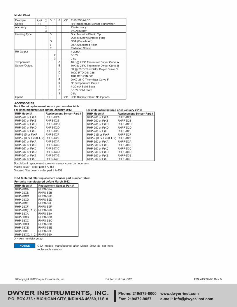
Example
Series
Accuracy
Housing Type
RH Output
Temperature
Sensor/Output
Option
RHP
RHP
2
2
3
D
D
F
O
S
R
1
1
2
3
A
A
B
C
D
E
F
0
1
2
3
LCD
LCD
RHP-2D1A-LCD
RH/Temperature Sensor Transmitter
2% Accuracy
3% Accuracy
Duct Mount w/Plastic Tip
Duct Mount w/Sintered Filter
OSA (Outside Air)
OSA w/Sintered Filter
Radiation Shield
4-20mA
0-10V
0-5V
10K @ 25°C Thermistor Dwyer Curve A
10K @ 25°C Thermistor Dwyer Curve B
3K @ 25°C Thermistor Dwyer Curve C
100Ω RTD DIN 385
1KΩ RTD DIN 385
20KC 25°C Thermistor Curve F
No Temperature Output
4-20 mA Solid State
0-10V Solid State
0-5V
LCD Display; Blank: No Options
Model Chart
ACCESSORIES
RHP Model #
RHP-2(D or F)XA
RHP-2(D or F)XB
RHP-2(D or F)XC
RHP-2(D or F)XD
RHP-2(D or F)XE
RHP-2 (D or F)XF
RHP-2 (D or F)X(0,1, 2)
RHP-3(D or F)XA
RHP-3(D or F)XB
RHP-3(D or F)XC
RHP-3(D or F)XD
RHP-3(D or F)XE
RHP-3(D or F)XF
Replacement Sensor Part #
RHPF-D2A
RHPF-D2B
RHPF-D2C
RHPF-D2D
RHPF-D2E
RHPF-D2F
RHPF-D20
RHPF-D3A
RHPF-D3B
RHPF-D3C
RHPF-D3D
RHPF-D3E
RHPF-D3F
For units manufactured after January 2012:
OSA models manufactured after March 2012 do not have
replaceable sensors.
NOTICE
E-90-RHP_E-90-RH 8/21/12 10:12 AM Page 4
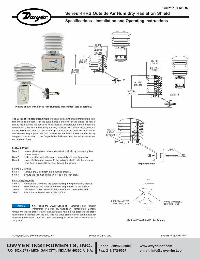
Bulletin H-RHRS
The Series RHRS Radiation Shield protects outside air humidity transmitters from
rain and radiated heat. With the curved shape and color of the plates, air flow is
able to move across the sensor to keep radiated temperatures from rooftops and
surrounding surfaces from affecting humidity readings. For ease of installation, the
Series RHRS has integral pipe mounting hardware which can be removed for
surface mounting applications. The brackets on the Series RHRS are specifically
designed to be installed on the Dwyer Series RHP outside air humidity transmitters
with sintered filters.
INSTALLATION
Step 1: Loosen plastic probe retainer on radiation shield by unscrewing two
retainer screws.
Step 2: Slide humidity transmitter probe completely into radiation shield.
Step 3: Screw plastic probe retainer to the radiation shield until the probe is
firmly held in place. Do not over tighten the screws.
For Pipe Mounting
Step 4: Remove the u-bolt from the mounting bracket.
Step 5: Secure the radiation shield to 3/4˝ to 1-1/2˝ iron pipe.
For Surface Mounting
Step 4: Remove the u-bolt and the screw holding the pipe retaining bracket.
Step 5: Mark the outer two holes of the mounting bracket on the surface.
Step 6: Drill the two holes marked in the previous step into the surface.
Step 7: Attach the radiation shield to the surface.
DWYER INSTRUMENTS, INC. Phone: 219/879-8000 www.dwyer-inst.com
P.O. BOX 373 • MICHIGAN CITY, INDIANA 46360, U.S.A. Fax: 219/872-9057 e-mail: [email protected]
Specifications - Installation and Operating Instructions
Series RHRS Outside Air Humidity Radiation Shield
©Copyright 2012 Dwyer Instruments, Inc. Printed in U.S.A. 2/12 FR# R6-443825-00 Rev.1
Picture shown with Series RHP Humidity Transmitter (sold separately)
ø5-1/8[130.18]
4-31/32[126.21]
8-43/64[220.27]
ø4-47/64[120.25]
Ø5-1/8[130.18]
Ø4-47/64[120.25]
6-13/64[157.65]
10-37/64[268.73] RHRS-10
If not using the Dwyer Series RHP Sintered Filter Humidity
Transmitter or Series TE Outside Air Temperature Sensor,
remove the plastic probe retainer and substitute with the two-sided plastic probe
retainer that is included with the unit. This two-sided probe retainer can be used for
probe diameters from 0.400˝ to 0.690˝ depending on which side of the retainer is
being used.
NOTICE
PLASTICPROBE
RETAINER
U-BOLT
Exploded-View
PROBE DIAMETERS0.40˝ THRU 0.49˝
PROBE DIAMETERS0.50˝ THRU 0.69˝
O Optional Two Sided Probe Retainer
H-RHRS_TEMPLATE 2/22/12 2:04 PM Page 1
Recommended