Embed Size (px)
Citation preview
Transmitter features
Humidity
ALU or ABS housing
WITH or WITHOUT display
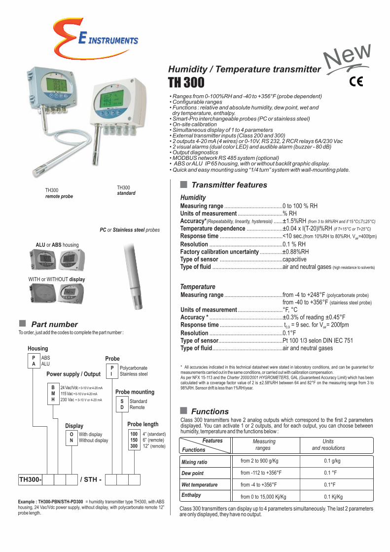
TH300remote probe
TH300standard
• Ranges from 0-100%RH and -40 to +356°F (probe dependent)• Configurable ranges• Functions : relative and absolute humidity, dew point, wet and dry temperature, enthalpy.
• Smart-Pro interchangeable probes (PC or stainless steel)• On-site calibration• Simultaneous display of 1 to 4 parameters• External transmitter inputs (Class 200 and 300) • 2 outputs 4-20 mA (4 wires) or 0-10V, RS 232, 2 RCR relays 6A/230 Vac• 2 visual alarms (dual color LED) and audible alarm (buzzer - 80 dB)• Output diagnostics• MODBUS network RS 485 system (optional)• ABS or ALU IP 65 housing, with or without backlit graphic display.• Quick and easy mounting using “1/4 turn” system with wall-mounting plate.
Measuring range .......................................0 to 100 % RHUnits of measurement ..............................% RHAccuracy*(Repeatability, linearity, hysteresis) ......±1.5%RH (from 3 to 98%RH and if 15°C T 25°C)
Temperature dependence ........................±0.04 x I(T-20)I%RH (if T<15°C or T>25°C)
Response time ..........................................<10 sec.(from 10%RH to 80%RH, V =400fpm)air
Resolution .................................................0.1 % RHFactory calibration uncertainty ...............±0.88%RHType of sensor ..........................................capacitiveType of fluid ...............................................air and neutral gases (high resistance to solvents)
Measuring range .......................................from -4 to +248°F (polycarbonate probe)
from -40 to +356°F (stainless steel probe)
Units of measurement ..............................°F, °CAccuracy * .................................................±0.3% of reading ±0.45°FResponse time .......................................... t = 9 sec. for V = 200fpm0,9 air
Resolution .................................................0.1°FType of sensor...........................................Pt 100 1/3 selon DIN IEC 751Type of fluid...............................................air and neutral gases
....................................................................
Temperature
Part number
TH300- / STH -
100 4” (standard)150 6” (remote)300 12” (remote)
P ABSA ALU
Housing
P PolycarbonateI Stainless steel
Probe
Probe mounting
Probe length
To order, just add the codes to complete the part number :
Example : TH300-PBN/STH-PD300 = humidity transmitter type TH300, with ABS housing, 24 Vac/Vdc power supply, without display, with polycarbonate remote 12” probe length.
S StandardD Remote
B 24 Vac/Vdc
M 115 Vac
H 230 Vac • 0-10 V or 4-20 mA
• 0-10 V or 4-20 mA
• 0-10 V or 4-20 mA
Power supply / Output
Display
O With displayN Without display
Functions
Measuring Units ranges and resolutions
from 2 to 900 g/Kg 0.1 g/kg
from -112 to +356°F 0.1 °F
from -4 to +356°F 0.1°F
from 0 to 15,000 Kj/Kg 0.1 Kj/Kg
Functions
Features
Mixing ratio
Dew point
Wet temperature
Enthalpy
PC or Stainless steel probes
Class 300 transmitters have 2 analog outputs which correspond to the first 2 parameters displayed. You can activate 1 or 2 outputs, and for each output, you can choose between humidity, temperature and the functions below :
Class 300 transmitters can display up to 4 parameters simultaneously. The last 2 parameters are only displayed, they have no output.
weN weNHumidity / Temperature transmitter
TH 300
* All accuracies indicated in this technical datasheet were stated in laboratory conditions, and can be guaranted for measurements carried out in the same conditions, or carried out with calibration compensation.As per NFX 15-113 and the Charter 2000/2001 HYGROMETERS, GAL (Guaranteed Accuracy Limit) which has been calculated with a coverage factor value of 2 is ±2.58%RH between 64 and 82°F on the measuring range from 3 to 98%RH. Sensor drift is less than 1%RH/year.
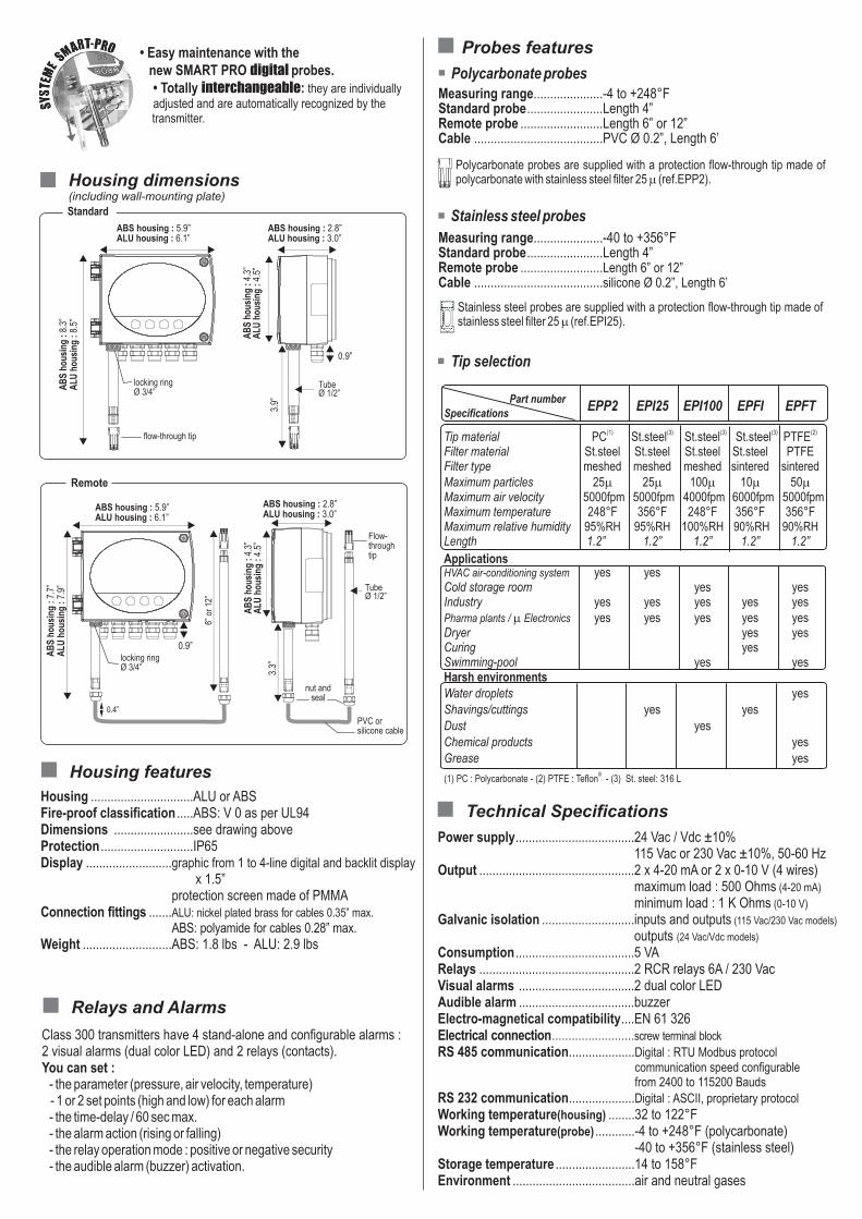
Technical Specifications
Power supply....................................24 Vac / Vdc ±10%115 Vac or 230 Vac ±10%, 50-60 Hz
Output ...............................................2 x 4-20 mA or 2 x 0-10 V (4 wires)maximum load : 500 Ohms (4-20 mA)
minimum load : 1 K Ohms (0-10 V)
Galvanic isolation ............................inputs and outputs (115 Vac/230 Vac models)
outputs (24 Vac/Vdc models)
Consumption....................................5 VARelays ...............................................2 RCR relays 6A / 230 VacVisual alarms ...................................2 dual color LEDAudible alarm ...................................buzzerElectro-magnetical compatibility....EN 61 326Electrical connection screw terminal block
RS 485 communication....................Digital : RTU Modbus protocolcommunication speed configurable from 2400 to 115200 Bauds
RS 232 communication....................Digital : ASCII, proprietary protocol
Working temperature(housing) ........32 to 122°FWorking temperature(probe) ............-4 to +248°F (polycarbonate)
-40 to +356°F (stainless steel)Storage temperature ........................14 to 158°FEnvironment .....................................air and neutral gases
...........................................................
...........................................................
..................................................................
..................................................................
...........................................................
.........................
Measuring range.....................-4 to +248°FStandard probe.......................Length 4”Remote probe .........................Length 6” or 12”Cable .......................................PVC Ø 0.2”, Length 6’
Probes features
Housing ...............................ALU or ABSFire-proof classification .....ABS: V 0 as per UL94Dimensions ........................see drawing aboveProtection ............................IP65Display ..........................graphic from 1 to 4-line digital and backlit display
x 1.5”protection screen made of PMMA
Connection fittings .......ALU: nickel plated brass for cables 0.35” max.
ABS: polyamide for cables 0.28” max.Weight ...........................ABS: 1.8 lbs - ALU: 2.9 lbs
.......................................2.8”
.......................................
.......................................
Housing features
Polycarbonate probes
Tip selection
• Easy maintenance with thenew SMART PRO digital probes.• Totally interchangeable: they are individually adjusted and are automatically recognized by the transmitter.
Polycarbonate probes are supplied with a protection flow-through tip made of polycarbonate with stainless steel filter 25 m (ref.EPP2).
Remote
0.9”
Housing dimensions(including wall-mounting plate)
ABS housing : 2.8”ALU housing : 3.0”
ABS housing : 2.8”ALU housing : 3.0”
3.9”
3.3”
6”
or
12”
0.9”
ABS housing : 5.9”ALU housing : 6.1”
ABS housing : 5.9”ALU housing : 6.1”
Standard
AB
S h
ousi
ng :
8.3”
ALU
hou
sing
: 8.
5”
AB
S h
ousi
ng :
7.7”
ALU
hou
sing
: 7.
9”
ALU
hou
sing
: 4.
5”A
BS
hou
sing
: 4.
3”
PVC or silicone cable
TubeØ 1/2”
nut andseal
locking ringØ 3/4”
TubeØ 1/2”
Flow-throughtip
ALU
hou
sing
: 4.
5”A
BS
hou
sing
: 4.
3”Measuring range.....................-40 to +356°FStandard probe.......................Length 4”Remote probe .........................Length 6” or 12”Cable .......................................silicone Ø 0.2”, Length 6’
Stainless steel probes are supplied with a protection flow-through tip made of stainless steel filter 25 m (ref.EPI25).
Stainless steel probes
locking ringØ 3/4”
flow-through tip
0.4”
Class 300 transmitters have 4 stand-alone and configurable alarms : 2 visual alarms (dual color LED) and 2 relays (contacts). You can set : - the parameter (pressure, air velocity, temperature) - 1 or 2 set points (high and low) for each alarm - the time-delay / 60 sec max. - the alarm action (rising or falling) - the relay operation mode : positive or negative security - the audible alarm (buzzer) activation.
Relays and Alarms
Part numberSpecifications
EPP2 EPI25 EPI100 EPFI EPFT
(1) (3) (2)Tip material PC PTFEFilter material St.steel St.steel St.steel St.steel PTFEFilter type meshed meshed meshed sintered sinteredMaximum particles 25m25m100m10m50mMaximum air velocity 5000fpm 5000fpm 4000fpm 6000fpm 5000fpmMaximum temperature 248°F 356°F 248°F 356°F 356°FMaximum relative humidity 95%RH 95%RH 100%RH 90%RH 90%RHLength 1.2” 1.2” 1.2” 1.2” 1.2”
ApplicationsHVAC air-conditioning system yes yesCold storage room yes yesIndustry yes yes yes yes yesPharma plants / m Electronics yes yes yes yes yesDryer yes yesCuring yesSwimming-pool yes yesHarsh environmentsWater droplets yesShavings/cuttings yes yesDust yesChemical products yesGrease yes
® (1) PC : Polycarbonate - (2) PTFE : Teflon - (3) St. steel: 316 L
(3) (3)St.steel St.steel St.steel
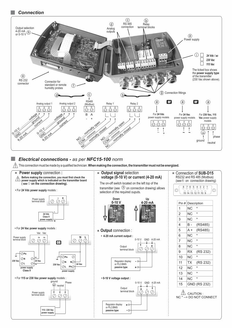
Connection
bd { {
0-10 V
. .....
......
..volta
ge
GND
......
......
.....g
round
4-20 m
A. .....
.....c
urrent
0-10 V
......
......
..volta
ge
GND...
......
......
..gro
und
4-20 m
A...
......
..curre
nt
B
-
A
+
NO...
...norm
ally o
pen
COM...
com
mon
NC...
...norm
ally cl
osed
Analog output 1 Analog output 2 Relay 1 Relay 2
Connection fittings
Power supplya
g
RS 232connector
e
Connector for standard or remotehumidity probes
f
Relayterminal blocks
RS 485connection
Analog outputs
bcd
Output selection4-20 mAor 0-10 V
h
Electrical connections - as per NFC15-100 normThis connection must be made by a qualified technician. When making the connection, the transmitter must not be energized.!
NO...
...norm
ally o
pen
COM...
com
mon
NC...
...norm
ally cl
osed
a
For 230 Vac, 115 Vac power supply
models
groundneutral
phase
Power supply connection :
a
For 24 Vdcpower supply models
_+
or
• For 24 Vdc power supply models :
• For 115 or 230 Vac power supply models :
- +
-
+
Power supplyterminal block
The on-off switch located on the left top of the
transmitter (see on connection drawing) allows selection of the required ouputs.
h
Down 0-10 V
Up 4-20 mA
Output signal selection voltage (0-10 V) or current (4-20 mA)
12345678
9101112131415
Pin # Description
1 NC *
2 NC *
3 NC *
4 B - (RS485)
5 A + (RS485)
6 NC *
7 NC *
8 NC *
9 RX (RS 232)
10 NC *
11 TX (RS 232)
12 NC *
13 NC *
14 NC *
15 GND (RS 232)
CAUTION :NC * --> DO NOT CONNECT
!
• 0-10 V voltage output :
• 4-20 mA current output :
Output connection :
a
For 24 Vacpower supply models
~ ~
neutral
115 / 230 Vacpower supply
ground
• 24 Vac power supply models :For
Phase
- +
Regulator displayor PLC/BMSpassive type
-
+
Output terminal block
4-20 mAGND0-10 V
-+
Regulator displayor PLC/BMSpassive type -
+
4-20 mAGND0-10 V
The ticked box showsthe power supply typeof the transmitter(230 Vac shown above).
i
! Before making the connection, you must first check the power supply which is indicated on the transmitter board ( see on the connection drawing).i
230 Vac
115 Vac
24 Vdc / ac
Connection of SUB-D15RS232 and RS 485 (Modbus)(see on connection drawing)e
or
Power supplyterminal block
Output terminal block
24 VdcClass II
power supply
N L
N
Ph
Pe
~ ~
~
~
Vac Vac
N
L
N
L24 Vac
24 Vac
Pe
230 Vac
230 Vac
OR
power supply
Class II
Power supplyterminal block
power supply
c
RS485(Modbus)
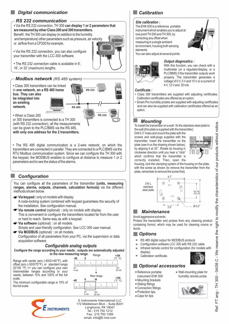
Avoid aggressive solvents.Protect the transmitter and probes from any cleaning product containing formol, which may be used for cleaning rooms or ducts.
Maintenance
Options
RS 485 digital output for MODBUS protocolConfiguration software LCC 300 with RS 232 cableInfrared remote control for configuration (for models with display)Calibration certificate.
Reference portable instrument EHK 500Mounting bracketsSliding fittingsConnection fittingsProtection tipsCaps for tips
Optional accessories
Mounting
316 L stainless
steel plate
A
A
4.7”
Ø 0.2”2.6”
3.9”
2.6
”
Configuration
Modbus network (RS 485 system)
• Class 300 transmitters can be linked in one network, on a RS 485 home bus. They can also be integrated into an existing network.
• When a Class 200 or 300 transmitters is connected to a TH 300 (with RS 232 connection), all the measurements can be given to the PLC/BMS via the RS 485, with only one address for the 2 transmitters.
RS 485
RS 232
RS 232
CalibrationDigital communication
• Via the RS 232 connection, TH 300 can display 1 or 2 parameters that are measured by other Class 200 and 300 transmitters. Benefit : the TH 300 can display (in addition to the humidity and temperature) other parameters such as pressure, air velocityor airflow from a CP200 for example.
• Via the RS 232 connection, you can also configure your transmitter with the LCC-300 software.
• The RS 232 connection cable is available in 6’, 16’, or 32’ (maximum) lengths.
RS 232 communication
Wall-mounting plate for humidity remote probe
Site calibration :The EHK 500 is a reference portableinstrument which enables you to adjust atone point TH 200 and TH 300, bycorrecting any offset whenmeasuring in a single ambientenvironment, housing both sensingelements. You can also adjust at several points.
Output diagnostics :With this function, you can check with a multimeter (or a regulator/display, or a PLC/BMS) if the transmitter outputs work properly. The transmitter generates a voltage of 0 V, 5 V and 10 V or a current of 4 V, 12 V and 20 mA.
Certificate :• Class 300 transmitters are supplied with adjusting certificates. Calibration certificates are offered as an option.• Smart-Pro humidity probes are supplied with adjusting certificates and can also be supplied with calibration certificates offered as an option.
To install the transmitter on a wall : fix the stainless steel plate to the wall (this plate is supplied with the transmitter).Drill 0.3” holes and mount the plate with the screws and wall-plugs supplied with the transmitter. Insert the transmitter on the plate (see A on the drawing shown below), by aligning it at 30°. Rotate its housing in clockwise direction until you hear a “click” which confirms that the transmitter is correctly installed. Then, open the housing, lock the clamping system of the housing on the plate, with the screw as shown (to remove the transmitter from the plate, remember to remove the screw first).
• The RS 485 digital communication is a 2-wire network, on which the transmitters are connected in parallel. They are connected to a PLC/BMS via the RTU Modbus communication system. Since we can configure the TH 300 with the keypad, the MODBUS enables to configure at distance to measure 1 or 2 parameters and to see the status of the alarms.
You can configure all the parameters of the transmitter (units, measuring ranges, alarms, outputs, channels, calculation formula) via the different methods shown below.
Via keypad : only on models with display
Via remote control (optional) : only on models with display
Via software (optional) : on all models.Simple and user-friendly configuration. See LCC-300 user manual.
A code-locking system combined with keypad guarantees the security of the installation. See configuration manual.
This is convenient to configure the transmitters located far from the user or hard to reach. Same way as with a keypad.
Via MODBUS (optional) : on all models.Configuration of all parameters from your PC, via the supervision or data acquisition software.
Range with center zero (-40/0/+40°F), with offset zero (-30/0/70°F), or standard range (0/100 °F) => you can configure your own intermediate ranges according to your needs, between 10% and 100% of the full scale.The minimum configurable range is 10% of the full scale.
Configure the range according to your needs : outputs are automatically adjusted to the new measuring range.
Configurable analog outputs
New range
Range-40
+356(°F, °C)
0V4 mA
10V20 mA
-40 50
0V4 mA
10V20 mA
0
+356(°F, °C)0
Ref. F
T a
ng
- T
H 3
00
- 0
4/0
8 C
- W
e r
ese
rve
the
rig
ht to
modify
the
chara
cterist
ics o
f our
pro
duct
s w
ithout notic
e.
E Instruments International LLC172 Middletown Blvd. - Suite B201
Langhorne, PA 19047Tel.: 215 750 1212Fax.: 215 750 1399
email: [email protected]