8/10/2019 Separatoare Web Gd Uk
http://slidepdf.com/reader/full/separatoare-web-gd-uk 1/15
11❙ PRE-TREATMENT ❙ 2008
Oil separatorsLarge f lows 25 > 250 l/sec
OIL SEPARATORS LARGE FLOWS
I N T R O
C L A S S E S
C H O O S E
C O N F O R M I T Y
T E S
T S
T A N K
O P E R A T I O N
A L A R M
A C C E S S O R I E S
I N S T A L L A T I O N
T E C H N I C A L
S P E C I F I C A T I O N
8/10/2019 Separatoare Web Gd Uk
http://slidepdf.com/reader/full/separatoare-web-gd-uk 2/15
2
EN858-1
❙ PRE-TREATMENT ❙ 2008
C L A S S E S
C H O O S E
C O N F O R M I T Y
T E S
T S
T A N K
O P E R A T I O N
A L A R M
A C C E S S O R I E S
I N S T A L L A T I O N
TECHNICAL
S P E C I F I C A T I O N
I N T R O
Oil separators
Requirements◢
An oil separator is designed to catch the source of pollutants
carried by run-off waters.We offer a wide range of oil separators conform to standardsEN 858-1.
Fields of application◢
According to current rules, the oil separators have to be used
for the pre-treatment of surface waters carrying hydrocar-bons, for example:
To treat waters stemming from industrial▢
processes, from the washing of vehicles, fromthe cleaning of oil coated elements.
To treat rainy waters (drainage waters)▢
contaminated by the oil resulting from waterproof
zones (car parks, roads, factories, …).To hold wide-spread light liquids and to protect▢
the surrounding zone (gas stations)
Advices◢
The rule becomes more and more strict as regards the1.
quantity of hydrocarbons rejected in natural environ-ment. It is the reason why we advise to rather use de-vices provided with a coalescing filter which assures ahydrocarbon discharge lower than 5 mg/l.The good working of the separator imposes a sludge2.trap large enough for allowing the settling of muds (seefollowing page).The installation of the separator will largely be facili-3.tated if the level of water has been correctly measured.We propose, for that purpose, fixed or adjustable exten-sion shafts which allow to position the device withoutproblem.
8/10/2019 Separatoare Web Gd Uk
http://slidepdf.com/reader/full/separatoare-web-gd-uk 3/15
3❙ PRE-TREATMENT ❙ 2008
I N T R O
C H O O S E
C O N F O R M I T Y
T E S
T S
T A N K
O P E R A T I O N
A L A R M
A C C E S S O R I E S
I N S T A L L A T I O N
T E C H N I C A L
S P E C I F I C A T I O N
C L A S S E S
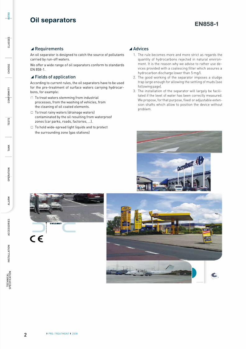
Classes of separators
There are 2 classes of separators:◢
Class 1: with coalescing filter▢ Residual content lower than 5 mg/l according to essay standard EN 858.
Class 2: without coalescing filter▢
Residual content lower than 100 mg/l according to essay standard EN 858.
Choice of the treatment
1. Total treatment◢ (device without by-pass storm overflow)
Installation straight on the net
For large surfaces with risk of accidentalpollution.
Example : hydrocarbons storage areas,
fuel distribution centers.
Installation right after the storm basin
with flow regulator
with risk of accidental pollution.The basin requires a lot of space.
2. Partial treatment◢ (device with by-pass storm overflow)
Installation straight on the net,
with by-pass device in the separator
For large surfaces with risk of accidentallimited pollution.
Example: parking areas, roads.
Installation in by-pass on the net,with by-pass device upstream the separator
For very large surfaces and on an existing net.
8/10/2019 Separatoare Web Gd Uk
http://slidepdf.com/reader/full/separatoare-web-gd-uk 4/15
4 ❙ PRE-TREATMENT ❙ 2008
I N T R O
C L A S S E S
C O N F O R M I T Y
T E S
T S
T A N K
O P E R A T I O N
A L A R M
A C C E S S O R I E S
I N S T A L L A T I O N
TECHNICAL
S P E C I F I C A T I O N
C H O O S E
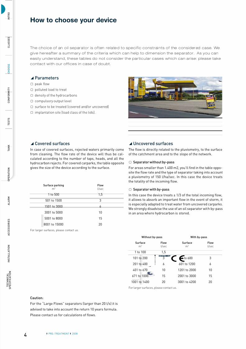
1 to 500 1,5
501 to 1500 3
1501 to 3000 6
3001 to 5000 10
5001 to 8000 15
8001 to 15000 20
1 to 100 1,5
101 to 200 3 1 to 600 3
201 to 400 6 601 to 1200 6
401 to 670 10 1201 to 2000 10
671 to 1000 15 2001 to 3000 15
1001 to 1400 20 3001 to 4200 20
How to choose your device
The choice of an oi l separ ator is often relate d to specif ic constrai nts of the consider ed case. We
give hereafter a summary of the cr i ter ia which can help to dimension the separator. As you can
easi ly understand, these tables do not consider the part icular cases which can ar ise: please take
contact with our off ices in case of doubt.
Covered surfaces◢
In case of covered surfaces, rejected waters primarily come
from cleaning. The flow rate of the device will thus be cal-culated according to the number of taps, heads, and all thehydrocarbon rejects. For covered carparks, the table opposite
gives the size of the device according to the surface.
Uncovered surfaces◢
The flow is directly related to the pluviometry, to the surface
of the catchment area and to the slope of the network.
Separator without by-pass▢
For areas smaller than 1.400 m2, you’ll find in the table oppo-
site the flow rate and the type of separator taking into accounta pluviometry of 150 l/ha/sec. In this case the device treatsthe totality of the incoming flow.
Separator with by-pass▢
In this case the device treats ± 1/3 of the total incoming flow,it allows to absorb an important flow in the event of storm, it
is especially adapted to treat water from uncovered carparks.We strongly disadvise the use of an oil separator with by-passin an area where hydrocarbon is stored.
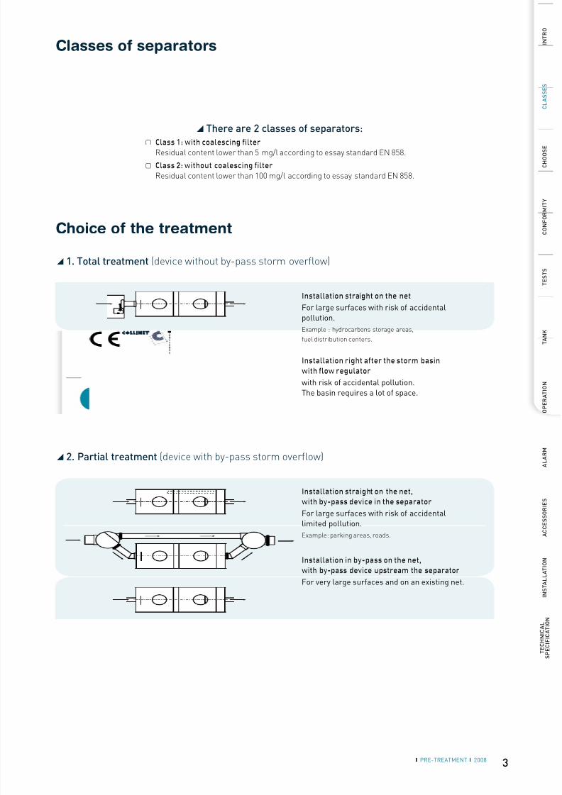
Parameters◢
peak flow▢
polluted load to treat▢
density of the hydrocarbons▢
compulsory output level▢
surface to be treated (covered and/or uncovered)▢
implantation site (load class of the lids).▢
Surface parkingm2
Flowl/sec
For larger surfaces, please contact us.
Without by-pass With by-pass
Surfacem2
Flowl/sec
Surfacem2
Flowl/sec
For larger surfaces, please contact us.
Caution:
For the “Large Flows” separators (larger than 20 l/s) it is
advised to take into account the return 10 years formula.
Please contact us for calculations of flows.
8/10/2019 Separatoare Web Gd Uk
http://slidepdf.com/reader/full/separatoare-web-gd-uk 5/15
5
EN858-1
Débi t
N S
Cl .
Type
Capacité séparateur
Capacité débourbeur
Capacité stockage
Epaisseur couche
Année de fabrication
L/S Ref.
# SérieSerial #
Capacity separator
Capacity sludge trap
Storage hydrocarbons
Thickness layerhydrocarbons
Manufacturing year
850 l
150 l
223 l
180 mm
2008
EN858 Séparateur hydrocarbures • Oil separator
1,5
1
SKPE1,5/150
3930
PARC INDUS. DES HAUTS-SARTS • B-4040 HERSTAL • BELGIUMTEL +32 (0)4.256.56.10 • FAX +32 (0)4.256.56.19 • www.collinet.eu
P .I. Haut s-Sar t s ❙ B-40 40 Her st al ❙ BE LGIUM ❙ � +32.4.256.56.10 ❙ +32.4.256.56.19 l ❙ T V A BE 0 432.17 2.9 0 9 ex por t @c ollinet .eu ❙ w w w .c ollinet .eu
E C d e cl ar at i on of conf or mi t y W e her eby guar ant ee and dec lar e t hat t he C E mar k ed pr oduc t , SE P AR AT O R , f ulf ils t he appli-
c able pr ov isions of t he D ir ec t iv e 89 / 10 6 / E E C c onc er ning separ at or sy st em f or light liquids as
w ell as t he E u r o p e a n nor me E N 8 5 8 - 1 “ Separ at or sy st ems f or light liquids ( e.g. oil and pet r ol).
P r inc iples of pr oduc t design, per f or manc e and t est ing, mar k ing and qualit y c ont r ol” .T his c er t if ic at e is v alid f or all dev ic es desc r ibed her e abov e and bear ing t he C E mar k ing o
r igi-
nat ing f r om t he f ollow ing sit es: C O LLINE T Assainissement s.a. , Her st al , Belgium and f or an
undet er mined per iod of t ime.
P la c e a nd d a t e of is s u e
S ig na t u r e of a n a u t hor i s e d p e r s on
Her st al, 11 / 0 9 / 20 0 6
Mr P ier re AND RE
Administ r at eur D élégué
❙ PRE-TREATMENT ❙ 2008
I N T R O
C L A S S E S
C H O O S E
T E S
T S
T A N K
O P E R A T I O N
A L A R M
A C C E S S O R I E S
I N S T A L L A T I O N
T E C H N I C A L
S P E C I F I C A T I O N
C O N F O R M I T Y
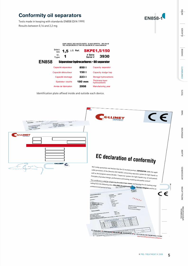
Conformity oil separatorsTests made in keeping with standards EN858 (DIN 1999)
Results between 0,16 and 2,2 mg
Identification plate affixed inside and outside each device.
8/10/2019 Separatoare Web Gd Uk
http://slidepdf.com/reader/full/separatoare-web-gd-uk 6/15
6 ❙ PRE-TREATMENT ❙ 2008
I N T R O
C L A S S E S
C H O O S E
C O N F O R M I T Y
T A N K
O P E R A T I O N
A L A R M
A C C E S S O R I E S
I N S T A L L A T I O N
TECHNICAL
S P E C I F I C A T I O N
T E S
T S
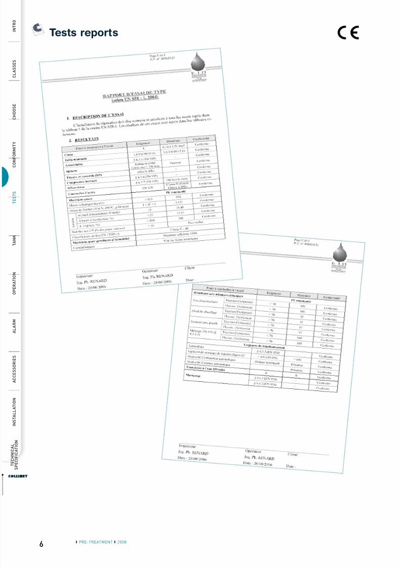
Tests reports
8/10/2019 Separatoare Web Gd Uk
http://slidepdf.com/reader/full/separatoare-web-gd-uk 7/15
7
3
15 15
8
14
6
11
9
51394
12
❙ PRE-TREATMENT ❙ 2008
I N T R O
C L A S S E S
C H O O S E
C O N F O R M I T Y
T E S
T S
O P E R A T I O N
A L A R M
A C C E S S O R I E S
I N S T A L L A T I O N
T E C H N I C A L
S P E C I F I C A T I O N
T A N K
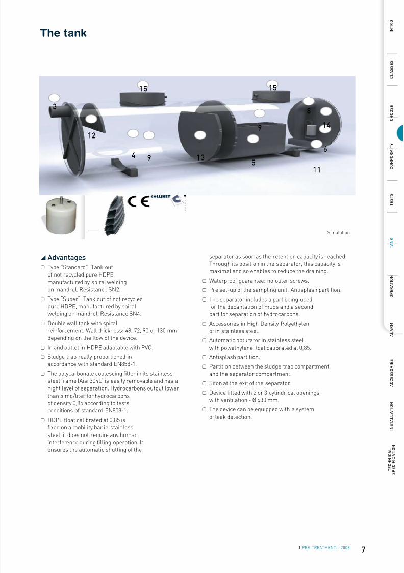
Simulation
Advantages◢
Type “Standard”: Tank out▢
of not recycled pure HDPE,manufactured by spiral weldingon mandrel. Resistance SN2.
Type “Super”: Tank out of not recycled▢
pure HDPE, manufactured by spiralwelding on mandrel. Resistance SN4.
Double wall tank with spiral▢
reinforcement. Wall thickness: 48, 72, 90 or 130 mmdepending on the flow of the device.
In and outlet in HDPE adaptable with PVC.▢
Sludge trap really proportioned in▢
accordance with standard EN858-1.
The polycarbonate coalescing filter in its stainless▢
steel frame (Aisi 304L) is easily removable and has ahight level of separation. Hydrocarbons output lowerthan 5 mg/liter for hydrocarbons
of density 0,85 according to testsconditions of standard EN858-1.
HDPE float calibrated at 0,85 is▢
fixed on a mobility bar in stainlesssteel, it does not require any humaninterference during filling operation. Itensures the automatic shutting of the
separator as soon as the retention capacity is reached.Through its position in the separator, this capacity ismaximal and so enables to reduce the draining.
Waterproof guarantee: no outer screws.▢
Pre set-up of the sampling unit. Antisplash partition.▢
The separator includes a part being used▢for the decantation of muds and a secondpart for separation of hydrocarbons.
Accessories in High Density Polyethylen▢
of in stainless steel.
Automatic obturator in stainless steel▢
with polyethylene float calibrated at 0,85.
Antisplash partition.▢
Partition between the sludge trap compartment▢
and the separator compartment.
Sifon at the exit of the separator.▢
Device fitted with 2 or 3 cylindrical openings▢
with ventilation - Ø 630 mm.The device can be equipped with a system▢
of leak detection.
The tank
8/10/2019 Separatoare Web Gd Uk
http://slidepdf.com/reader/full/separatoare-web-gd-uk 8/15
8 ❙ PRE-TREATMENT ❙ 2008
I N T R O
C L A S S E S
C H O O S E
C O N F O R M I T Y
T E S
T S
O P E R A T I O N
A L A R M
A C C E S S O R I E S
I N S T A L L A T I O N
TECHNICAL
S P E C I F I C A T I O N
T A N K
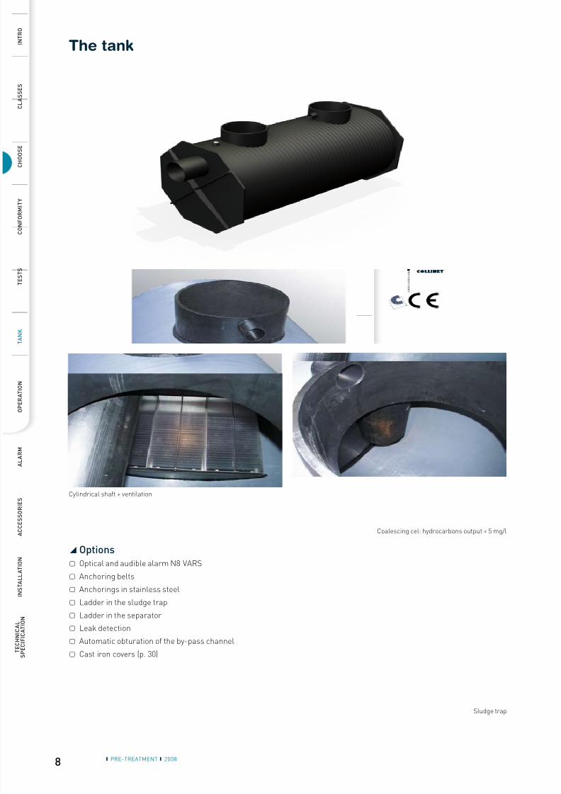
Options◢
Optical and audible alarm N8 VARS▢
Anchoring belts▢
Anchorings in stainless steel▢
Ladder in the sludge trap▢
Ladder in the separator▢
Leak detection▢
Automatic obturation of the by-pass channel▢
Cast iron covers (p. 30)▢
Cylindrical shaft + ventilation
Coalescing cel: hydrocarbons output < 5 mg/l
Sludge trap
The tank
8/10/2019 Separatoare Web Gd Uk
http://slidepdf.com/reader/full/separatoare-web-gd-uk 9/15
9❙ PRE-TREATMENT ❙ 2008
I N T R O
C L A S S E S
C H O O S E
C O N F O R M I T Y
T E S
T S
T A N K
A L A R M
A C C E S S O R I E S
I N S T A L L A T I O N
T E C H N I C A L
S P E C I F I C A T I O N
O P E R A T I O N
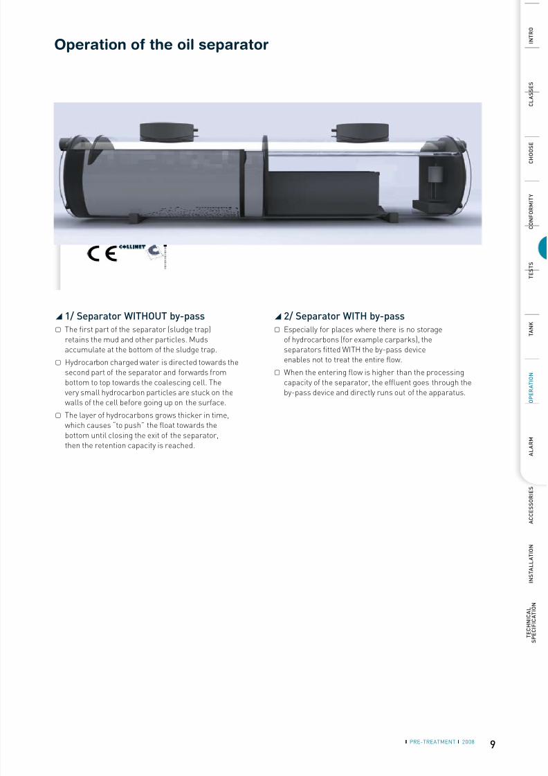
Operation of the oil separator
1/ Separator WITHOUT by-pass◢
The first part of the separator (sludge trap)▢
retains the mud and other particles. Mudsaccumulate at the bottom of the sludge trap.
Hydrocarbon charged water is directed towards the▢
second part of the separator and forwards frombottom to top towards the coalescing cell. Thevery small hydrocarbon particles are stuck on thewalls of the cell before going up on the surface.
The layer of hydrocarbons grows thicker in time,▢
which causes “to push” the float towards thebottom until closing the exit of the separator,then the retention capacity is reached.
2/ Separator WITH by-pass◢
Especially for places where there is no storage▢
of hydrocarbons (for example carparks), theseparators fitted WITH the by-pass deviceenables not to treat the entire flow.
When the entering flow is higher than the processing▢
capacity of the separator, the effluent goes through theby-pass device and directly runs out of the apparatus.
8/10/2019 Separatoare Web Gd Uk
http://slidepdf.com/reader/full/separatoare-web-gd-uk 10/15
10
1
5 5
4
3
2
6
1
2
3
4
5
6
❙ PRE-TREATMENT ❙ 2008
I N T R O
C L A S S E S
C H O O S E
C O N F O R M I T Y
T E S
T S
T A N K
A L A R M
A C C E S S O R I E S
I N S T A L L A T I O N
TECHNICAL
S P E C I F I C A T I O N
O P E R A T I O N
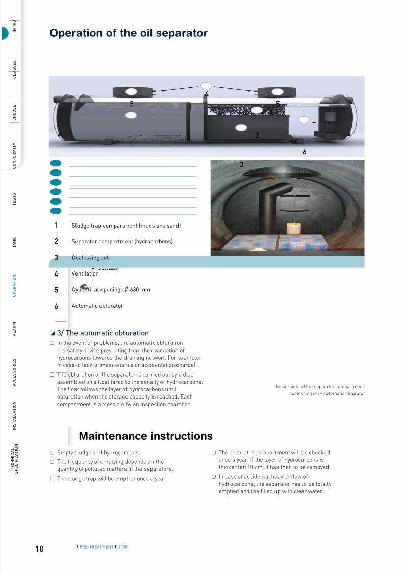
Sludge trap compartment (muds ans sand)
Separator compartment (hydrocarbons)
Coalescing cel
Ventilation
Cylindrical openings Ø 630 mm
Automatic obturator
3/ The automatic obturation◢
In the event of problems, the automatic obturation▢
is a safety device preventing from the evacuation ofhydrocarbons towards the draining network (for example:in case of lack of maintenance or accidental discharge).
The obturation of the separator is carried out by a disc▢
assembled on a float tared to the density of hydrocarbons.The float follows the layer of hydrocarbons untilobturation when the storage capacity is reached. Eachcompartment is accessible by an inspection chamber.
Maintenance instructions
Empty sludge and hydrocarbons.▢
The frequency of emptying depends on the▢
quantity of polluted matters in the separators.
The sludge trap will be emptied once a year.▢
The separator compartment will be checked▢
once a year. If the layer of hydrocarbons isthicker tan 10 cm, it has then to be removed.
In case of accidental heavier flow of▢
hydrocarbons, the separator has to be totallyemptied and the filled up with clear water.
Inside sight of the separator compartment:
coalescing cel + automatic obturator
Operation of the oil separator

8/10/2019 Separatoare Web Gd Uk
http://slidepdf.com/reader/full/separatoare-web-gd-uk 11/15
11❙ PRE-TREATMENT ❙ 2008
I N T R O
C L A S S E S
C H O O S E
C O N F O R M I T Y
T E S
T S
T A N K
O P E R A T I O N
A C C E S S O R I E S
I N S T A L L A T I O N
T E C H N I C A L
S P E C I F I C A T I O N
A L A R M
Level alarm
Hydrocarbon alarm in the separator: OILSET-1000◢
Hydrocarbon/mud alarm equipped with 2 probes: SANDOILSET-2000◢
Hydrocarbon/mud alarm fitted with 2probes : SANDOILSET-2000
One probe gives a signal when the layer ofhydrocarbon has been reached. The other
probe generates an alarm when the de-canted sand or mud level arises betweenthe two sensitive elements of the probe.
Approved: II (1) G, [EEx ia] II C, VTT 04
ATEX 031X
The level alarm OILSET-1000 has espe-cially been developed to detect an inter-face water/hydrocarbon in a separator.
It signals the right moment to carry outthe draining of the separator in order to
avoid rejecting hydrocarbons in the sew-ers. The control unit and probe SET-DM3are in accordance with directive ATEX
94/9/EC.
Approved: II (1) G, [EEx ia] II C, VTT 04ATEX 031X.
Control unit
Control unit
Hydrocarbons
Water
Hydrocarbons
Mud
Control unit
Hydrocarbons
Mud
Control unit
Hydrocarbons
Box IP65 (175 x125 x 75mm)Connection with cable 3 x 0,5 mm2
Box IP65 (175 x125 x 75mm)Connection with cable 3 x 0,5 mm2
Water
Water
Water
8/10/2019 Separatoare Web Gd Uk
http://slidepdf.com/reader/full/separatoare-web-gd-uk 12/15
12 ❙ PRE-TREATMENT ❙ 2008
I N T R O
C L A S S E S
C H O O S E
C O N F O R M I T Y
T E S
T S
T A N K
O P E R A T I O N
A C C E S S O R I E S
I N S T A L L A T I O N
TECHNICAL
S P E C I F I C A T I O N
A L A R M
Level alarm
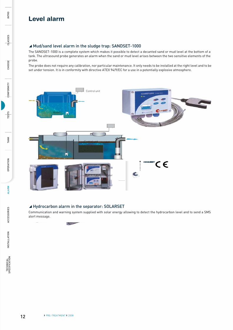
Mud/sand level alarm in the sludge trap: SANDSET-1000◢
The SANDSET-1000 is a complete system which makes it possible to detect a decanted sand or mud level at the bottom of a
tank. The ultrasound probe generates an alarm when the sand or mud level arises between the two sensitive elements of theprobe.
The probe does not require any calibration, nor particular maintenance. It only needs to be installed at the right level and to be
set under tension. It is in conformity with directive ATEX 94/9/EC for a use in a potentially explosive atmosphere.
Control unit
Mud
Control unit
Hydrocarbon alarm in the separator: SOLARSET◢
Communication and warning system supplied with solar energy allowing to detect the hydrocarbon level and to send a SMSalert message.
Water
Water
8/10/2019 Separatoare Web Gd Uk
http://slidepdf.com/reader/full/separatoare-web-gd-uk 13/15
13
Ø 610
F600 D-400 62 610 850 x 850
9 0
100
+ 30 mm
❙ PRE-TREATMENT ❙ 2008
I N T R O
C L A S S E S
C H O O S E
C O N F O R M I T Y
T E S
T S
T A N K
O P E R A T I O N
A L A R M
I N S T A L L A T I O N
T E C H N I C A L
S P E C I F I C A T I O N
A C C E S S O R I E S
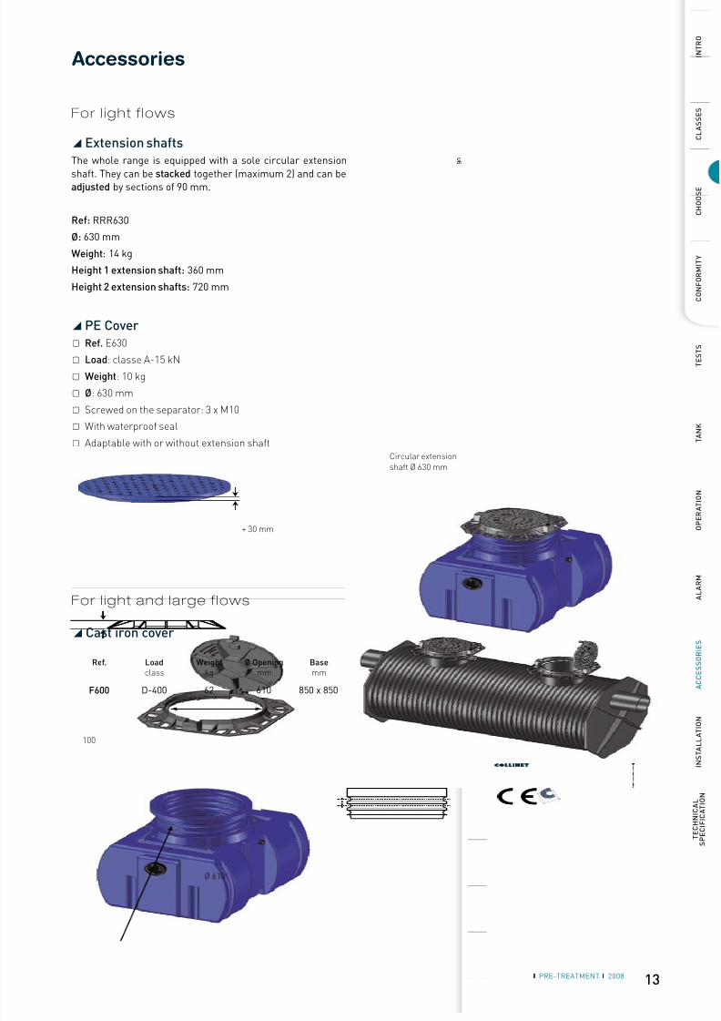
Accessories
Extension shafts◢
The whole range is equipped with a sole circular extension
shaft. They can be stacked together (maximum 2) and can beadjusted by sections of 90 mm.
Ref: RRR630
Ø: 630 mm
Weight: 14 kg
Height 1 extension shaft: 360 mm
Height 2 extension shafts: 720 mm
Ref. Loadclass
Weightkg
Ø Openingmm
Basemm
Cast iron cover◢
PE Cover◢
Ref.▢ E630
Load▢ : classe A-15 kN
Weight▢ : 10 kg
Ø▢ : 630 mm
Screwed on the separator: 3 x M10▢
With waterproof seal▢
Adaptable with or without extension shaft▢
Circular extensionshaft Ø 630 mm
For l ight f lows
For l ight and large f lows
8/10/2019 Separatoare Web Gd Uk
http://slidepdf.com/reader/full/separatoare-web-gd-uk 14/15
14 ❙ PRE-TREATMENT ❙ 2008
I N T R O
C L A S S E S
C H O O S E
C O N F O R M I T Y
T E S
T S
T A N K
O P E R A T I O N
A L A R M
A C C E S S O R I E S
TECHNICAL
S P E C I F I C A T I O N
I N S T A L L A T I O N
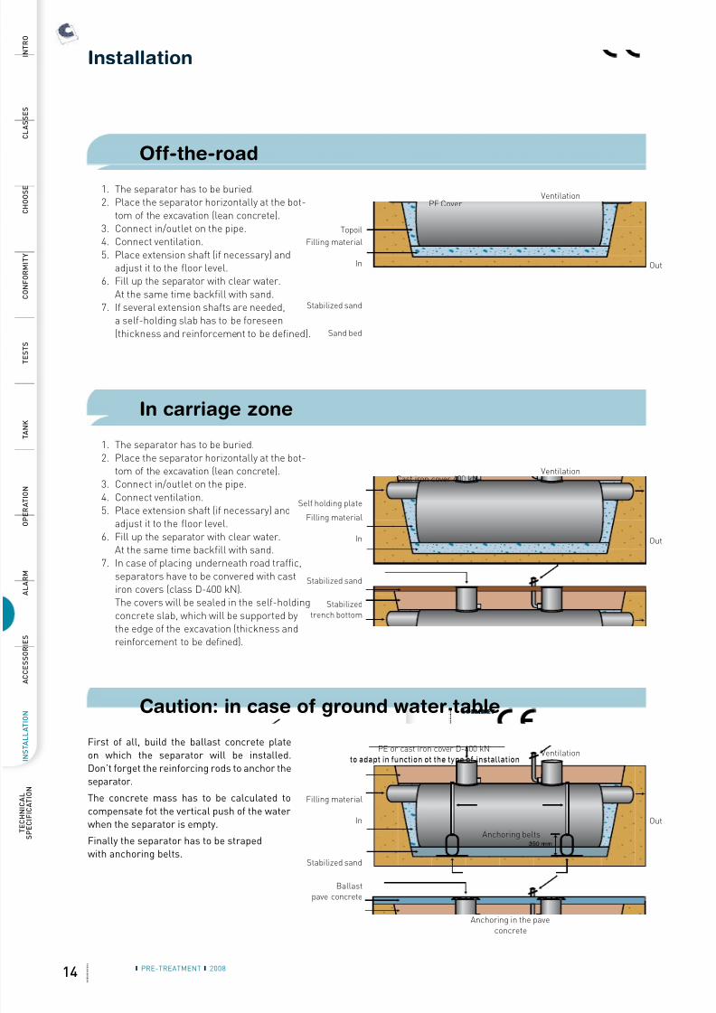
Installation
Off-the-road
The separator has to be buried.1.Place the separator horizontally at the bot-2.tom of the excavation (lean concrete).Connect in/outlet on the pipe.3.Connect ventilation.4.Place extension shaft (if necessary) and5.adjust it to the floor level.Fill up the separator with clear water.6.At the same time backfill with sand.If several extension shafts are needed,7.a self-holding slab has to be foreseen(thickness and reinforcement to be defined).
In carriage zone
The separator has to be buried.1.Place the separator horizontally at the bot-2.tom of the excavation (lean concrete).Connect in/outlet on the pipe.3.Connect ventilation.4.Place extension shaft (if necessary) and5.adjust it to the floor level.
Fill up the separator with clear water.6.At the same time backfill with sand.In case of placing underneath road traffic,7.separators have to be convered with castiron covers (class D-400 kN).The covers will be sealed in the self-holdingconcrete slab, which will be supported bythe edge of the excavation (thickness andreinforcement to be defined).
Caution: in case of ground water tableFirst of all, build the ballast concrete plate
on which the separator will be installed.Don’t forget the reinforcing rods to anchor theseparator.
The concrete mass has to be calculated to
compensate fot the vertical push of the waterwhen the separator is empty.
Finally the separator has to be strapedwith anchoring belts.
VentilationPE Cover
Topoil
Filling material
Stabilized sand
In Out
Sand bed
VentilationCast iron cover 400 kN
Self holding plate
Filling material
Stabilized sand
In Out
Stabilizedtrench bottom
VentilationPE or cast iron cover D-400 kNto adapt in function ot the type of installation
Filling material
Stabilized sand
In Out
Ballastpave concrete
Anchoring belts
Anchoring in the paveconcrete
8/10/2019 Separatoare Web Gd Uk
http://slidepdf.com/reader/full/separatoare-web-gd-uk 15/15
I N T R O
C L A S S E S
C H O O S E
C O N F O R M I T Y
T E S
T S
T A N K
O P E R A T I O N
A L A R M
A C C E S S O R I E S
I N S T A L L A T I O N
T E C H N I C A L
S P E C I F I C A T I O N
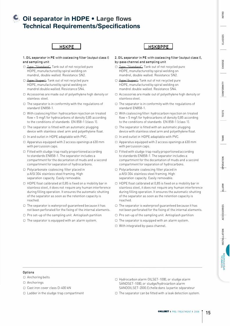
Oil separator in HDPE • Large flows Technical Requirements/Specifications
1. OIL separator in PE with coalescing filter (output class I)and sampling unit
Type “Standard”:▢ Tank out of not recycled pureHDPE, manufactured by spiral welding onmandrel, double walled. Resistance SN2.
Type “Super”:▢ Tank out of not recycled pureHDPE, manufactured by spiral welding onmandrel double walled. Resistance SN4.
Accessories are made out of polyethylene high density or▢
stainless steel.
The separator is in conformity with the regulations of▢
standard EN858-1.
With coalescing filter: hydrocarbon rejection on treated▢flow < 5 mg/l for hydrocarbons of density 0,85 accordingto the conditions of standards EN 858-1 (class 1).
The separator is fitted with an automatic plugging▢
device with stainless steel arm and polyethylene float.
In and outlet in HDPE adaptable with PVC.▢
Apparatus equipped with 2 access openings ø 630 mm▢
with percussion caps.
Fitted with sludge trap really▢ proportioned accordingto standards EN858-1. The separator includes acompartment for the decantation of muds and a secondcompartment for separation of hydrocarbons.
Polycarbonate coalescing filter▢
placed ina AISI 304 stainless steel framing. Highseparation capacity. Easily removable.
HDPE float calibrated at 0,85 is fixed on a mobility bar in▢
stainless steel, it does not require any human interferenceduring filling operation. It ensures the automatic shuttingof the separator as soon as the retention capacity isreached.
The separator is waterproof guaranteed because it has▢
not been perforated for the fixing of the internal elements.
Pre set-up of the sampling unit. Antisplash partition▢ .
The separator is equipped with an alarm system.▢
2. OIL separator in PE with coalescing filter (output class I),by-pass channel and sampling unit
Type “Standard”:▢ Tank out of not recycled pureHDPE, manufactured by spiral welding onmandrel, double walled. Resistance SN2.
Type “Super”:▢ Tank out of not recycled pureHDPE, manufactured by spiral welding onmandrel double walled. Resistance SN4.
Accessories are made out of polyethylene high density or▢
stainless steel.
The separator is in conformity with the regulations of▢
standard EN858-1.
With coalescing filter: hydrocarbon rejection on treated▢flow < 5 mg/l for hydrocarbons of density 0,85 accordingto the conditions of standards EN 858-1 (class 1).
The separator is fitted with an automatic plugging▢
device with stainless steel arm and polyethylene float.
In and outlet in HDPE adaptable with PVC.▢
Apparatus equipped with 2 access openings ø 630 mm▢
with percussion caps.
Fitted with sludge trap really▢ proportioned accordingto standards EN858-1. The separator includes acompartment for the decantation of muds and a secondcompartment for separation of hydrocarbons.
Polycarbonate coalescing filter▢
placed ina AISI 304 stainless steel framing. Highseparation capacity. Easily removable.
HDPE float calibrated at 0,85 is fixed on a mobility bar in▢
stainless steel, it does not require any human interferenceduring filling operation. It ensures the automatic shuttingof the separator as soon as the retention capacity isreached.
The separator is waterproof guaranteed because it has▢
not been perforated for the fixing of the internal elements.
Pre set-up of the sampling unit. Antisplash partition▢ .
The separator is equipped with an alarm system.▢
With integrated by-pass channel.▢
Options
Anchoring belts▢
Anchorings▢
Cast iron cover class D-400 kN▢
Ladder in the sludge trap compartment▢
Hydrocarbon alarm OILSET-1000, or sludge alarm▢
SANDSET-1000, or sludge/hydrocarbon alarmSANDOILSET-2000.Echelle dans la partie séparateur
The separator can be fitted with a leak detection system.▢
HSKPE HSKBPPE
Recommended