SDA T1 OCT Standard DRAFT Page 1 of 46
SDA Tranche 1 Optical Communications Terminal Standard Developed by the
Space Development Agency
Office of the Under Secretary of Defense Research and Engineering (USD(R&E)) 3030 Defense Pentagon Washington, D.C. 20301
Email: [email protected]
Date: 6/1/2021 Document ID: 20210601-001 This document is a DRAFT Standard and is subject to change. DISTRIBUTION A: Approved for Public Release: Distribution Unlimited

SDA T1 OCT Standard DRAFT Page 2 of 46
Table of Contents 1. Introduction ............................................................................................................................. 4
1.1. Elements of the OCT Standard ......................................................................................... 4
1.2. Requirements ................................................................................................................... 5
1.3. Normative Text ................................................................................................................. 5
1.4. Definitions ........................................................................................................................ 5
1.5. Table of Acronyms ............................................................................................................ 7
2. Layer 1 - Physical Layer ............................................................................................................ 9
2.1. Pointing, Acquisition, and Tracking (PAT) ........................................................................ 9
2.2. PAT State Machine ......................................................................................................... 10
2.2.1. States ....................................................................................................................... 10
2.2.2. State Machine ......................................................................................................... 10
2.2.3. State Transition Signals ........................................................................................... 10
2.2.4. State Transition Criteria Matrix .............................................................................. 11
2.2.5. Host Commands ...................................................................................................... 11
2.2.6. ACQUISITION State ................................................................................................. 11
2.2.7. ACQUISITION State Activities .................................................................................. 12
2.2.8. Acquisition Signal .................................................................................................... 12
2.2.9. PAT Acquisition Time .............................................................................................. 13
2.3. Modulation ..................................................................................................................... 13
2.4. Latency ........................................................................................................................... 13
2.5. Spectral Grid Definition .................................................................................................. 14
2.6. Transmit and Receive Wavelength ................................................................................ 14
2.7. Channel Selection ........................................................................................................... 14
2.8. Polarization ..................................................................................................................... 14
3. Layer 2 - Synchronization and Channel Coding Layer ........................................................... 15
3.1. Protocols ......................................................................................................................... 15
3.2. Re-Programming ............................................................................................................ 15
3.3. Effective Data Rate and Protocols .................................................................................. 15
3.4. Framing, Coding, and Encapsulation .............................................................................. 16
3.4.1. Frame Structure ...................................................................................................... 16

SDA T1 OCT Standard DRAFT Page 3 of 46
3.4.2. Error Control Coding ............................................................................................... 18
3.4.3. Frame Header ......................................................................................................... 21
3.4.4. Special Frames ........................................................................................................ 23
3.4.5. Ethernet Encapsulation ........................................................................................... 24
3.4.6. Effective Data Rate.................................................................................................. 29
3.5. Circulant Tables for Payload LDPC Code ........................................................................ 31
3.5.1. LDPC Code Tables .................................................................................................... 31
3.5.2. LDPC Code Rates ..................................................................................................... 38
4. References ............................................................................................................................. 39
5. Appendix A: Spiral Scan Definition ........................................................................................ 41
5.1. Spiral Scan ...................................................................................................................... 45
5.2. Nested Spiral Scan .......................................................................................................... 45

SDA T1 OCT Standard DRAFT Page 4 of 46
1. Introduction The purpose of this document is to provide the framework and protocol definitions for optical communications systems employed by the Space Development Agency (SDA) and its partners. The scope of optical communication links supported includes space-to-space (S2S, a.k.a. Optical Intersatellite Links or OISLs), space-to-air (S2A), space-to-maritime (S2M), and space-to-ground (S2G) optical communications.
The SDA OISL Standard [1] was first published in early 2020 [2] in preparation for the first iteration of the SDA spiral development process: Tranche 0. SDA’s Tranche 0 (T0) program added sufficient detail to the initial OISL Standard as to enable demonstration of multi-vendor interoperability. Since early 2020, significant advancements have been made across the Optical Communications Terminal (OCT) market. These advancements have prompted the addition of several protocols to the OISL Standard.
The document has been renamed the Optical Communications Terminal (OCT) Standard due to its applicability to S2G, S2M, and S2A links. This scope, being broader than ISLs alone, prompted the change.
This OCT Standard (the Standard) is intended to enable interoperability between optical communications where at least one endpoint is a space-based terminal.
1.1. Elements of the OCT Standard
This document provides descriptions of the Physical Layer and Synchronization and Channel Coding Sublayers as described by CCSDS. These correspond to Layer 1 and a portion of Layer 2 of the OSI Model, respectively. This document specifies the OCT to OCT interface.
The Physical Layer is the lowest layer. For the case of the OCT, the physical layer describes the laser parameters (e.g. wavelength, channel spacing, and spectral width) and the modulation parameters (e.g. OOK-NRZ or M-ary PPM). This section includes specifications of the user data rate, which, due to overhead from higher layers (e.g. from frame headers, error correction, etc.), is less than the user line rate.
In addition, unlike optical fiber, which provides a guided transmission medium between modems, free-space optical communications (FSOC) terminals must be spatially co-aligned. This requires the systems to accurately locate the remote terminal at range and point at the remote terminal with an accuracy sufficient to capture its signal. This acquisition process must be synchronous. In this Standard, real-time communications do not occur prior to establishment of the FSOC channel. This requires that the acquisition processes on the pair of terminals be both well-choreographed and synchronized to a common clock. This choreography is governed by the state machine (described in Section PAT State Machine) and its associated parameters.
For systems in motion, such as the OCTs used on spacecraft and aircraft, the systems must each track their remote counterpart in order to maintain alignment. This motion includes the general

SDA T1 OCT Standard DRAFT Page 5 of 46
flight path of the host platform as well as the jitter imparted by the platform. OCTs, whose receivers typically have relatively small fields-of-view (FOV), must compensate for this lower-rate motion and higher-rate jitter. This is accomplished through a closed-loop tracking system which uses the remote signal as the measurement reference. Corrections are fed to a coarse tracking apparatus (e.g. a gimbal) to correct the lower-rate motion and a fast tracking apparatus (e.g. a Fast Steering Mirror (FSM) to correct the higher-rate jitter.
The Synchronization and Channel Coding layer, which corresponds to the “lower” part of the OSI Model’s Layer 2 (see [3]), defines the tools necessary to permit largely error-free transmission (e.g. Forward Error Correction (FEC), scrambling, and line codes) as well as the structure of the data (e.g. framing).
1.2. Requirements
Requirements in this document take two forms:
1. Normative text indicating ‘shall’ or ‘must’
2. Enumerated Requirements, which will typically include normative text. These are specifically labeled for reference.
Enumerated requirements are assigned an ID and explicitly stated in this Standard in the following format:
Requirement OCT-<NNN>: <Requirement Description>
1.3. Normative Text
The following conventions apply for the normative specifications in this Specification:
a. the words ‘shall’ and ‘must’ indicate a binding and verifiable specification
b. the word ‘should’ indicates an optional, but desirable, specification
c. the word ‘may’ indicates an optional specification
d. the words ‘is’, ‘are’, and ‘will’ indicate statements of fact
1.4. Definitions
Term Definition Line Rate The gross bitrate of the physical layer of a communications channel. Line Rate
may also be referred to as the “raw bitrate,” “data signaling rate,” “gross data transfer rate,” or “uncoded transmission rate.” [4]
Bitrate The number of bits conveyed per unit of time. Line Code A pattern of voltage, current, or photons used to represent digital data
transmitted down a transmission line. [4]

SDA T1 OCT Standard DRAFT Page 6 of 46
User Rate The net bitrate of the communications channel. This is exclusive of protocol overhead (e.g. FEC). User Rate may also be referred to as the “payload rate” or “effective data rate.” The User Rate is always less than or equal to the Channel Capacity. [4]
Channel Capacity
The theoretical upper bound for the maximum net bitrate, exclusive of forward error correction coding, that is possible without bit errors for a certain physical analog node-to-node communication link. Channel capacity may also be referred to as the “Shannon Capacity.” [4]
Modulation Modulation is the process of varying one or more properties of a periodic waveform, called the carrier signal, with a separate signal called the modulation signal that typically contains information to be transmitted. [4]
Pseudo-Random Binary Sequence
A pseudorandom binary sequence (PRBS) is a binary sequence that, while generated with a deterministic algorithm, is difficult to predict and exhibits statistical behavior similar to a truly random sequence.
Amplitude Modulation (AM)
Amplitude modulation (AM) is a modulation technique used in electronic communication. In amplitude modulation, the amplitude (signal strength) of the carrier wave is varied in proportion to that of the message signal.
Radiance Radiance is the radiant flux transmitted, emitted, or received by a given surface per unit solid angle. The SI unit for radiance is the watt per square meter per (W/m2/per steradian).
Irradiance Irradiance is the radiant flux received by a surface per unit area. The SI unit for irradiance is the watt per square meter (W/m2).
Polarization Extinction Ratio (PER)
Ratio of optical powers for perpendicular polarizations.
Extinction Ratio
Extinction ratio is the ratio of two optical power levels of a signal generated by an optical source.
Solid Angle The angles defining the sensor, including, FOV and FOR, shall be expressed as a solid angle, typically specified in steradians, square degrees, or square radians. Alternatively, and perhaps more commonly, the solid angle of the sensor may be expressed in degrees, which means, by default, the solid angle defined by equal apex angles of a pyramid’s intersection with a sphere, which defines a spherical cap on a unit sphere. This represents a square sensor’s projection onto a sphere. Deviations of this pyramidal definition are permitted, the most common being a conical approximation, however such deviations must be explicitly annotated.
Field of Regard (FOR)
The field of regard is the total the solid angle defined by the allowable motion of the sensor combined with the field of view. The FOR, by default, refers to the terminal’s FOR.
Field of View (FOV)
The field of view is the solid angle that represents the instantaneous viewing angle of the sensor. Multiple FOVs may be defined for a sensor and is specified in-line sufficiently to indicate the applicable geometry. For example,

SDA T1 OCT Standard DRAFT Page 7 of 46
the system may have different FOVs for the communications, acquisition, and tracking channels. These three FOVs may be specified as the Communications Channel FOV, Acquisition FOV, and Tracking FOV.
Bit Numbering Convention
The convention used to identify each bit in an N-bit field will conform to Section 1.7 in (1).
Data and Symbol Rates
Data and symbol rates are expressed as bits-per-second (bps) and symbols-per-second (baud). Bps is defined as 1 bit/second. Similarly, baud is defined as 1 symbol/sec. SI-prefixes for these rates are expressed in base-10 and not in base-2. For example, 100 Mbps represents 100 x 10^6 bps or 10^8 bps.
Baud Rate Baud time is defined as the signaling time required to transmit a single coded frame bit and includes all sources of overhead including line code, preamble, header, cyclic redundancy checks (CRCs) and forward error correction (FEC). Baud rate, expressed in Hz, is the inverse of baud time.
Part Per Million (PPM)
A measurement used to quantify deviation from nominal value.
Modulation Index (MI)
Modulation index is a measure based on the ratio of the modulation excursions of a signal to the level of the unmodulated carrier.
Coded Bit-Error Rate
The number of bit errors per unit time prior to applying Forward Error Correction.
Decoded Bit-Error Rate
The number of bit errors per unit time prior to applying Forward Error Correction.
Packet Error Rate
The ratio of number of Ethernet packets received in error to total number of transmitted Ethernet packets.
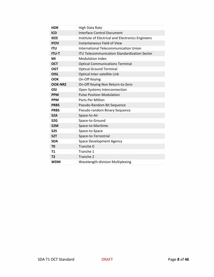
1.5. Table of Acronyms
Acronym Meaning ACK Acknowledgement AM Amplitude Modulation ANSI American National Standards Institute ARQ Automatic Repeat Request BER Bit-Error Rate CCSDS Consultative Committee for Space Data Systems CRC-16 Cyclic Redundancy Check with a 17-bit
polynomial. DCE Data Circuit-terminating Equipment DTE Data Terminal Equipment DWDM Dense WDM FCCH Fast Communications Channel FEC Forward Error Correction FOV Field of View
SDA T1 OCT Standard DRAFT Page 8 of 46
HDR High Data Rate ICD Interface Control Document IEEE Institute of Electrical and Electronics Engineers IFOV Instantaneous Field of View ITU International Telecommunication Union ITU-T ITU Telecommunication Standardization Sector MI Modulation Index OCT Optical Communications Terminal OGT Optical Ground Terminal OISL Optical Inter-satellite Link OOK On-Off Keying OOK-NRZ On-Off Keying Non Return-to-Zero OSI Open Systems Interconnection PPM Pulse Position Modulation PPM Parts Per Million PRBS Pseudo-Random Bit Sequence PRBS Pseudo-random Binary Sequence S2A Space-to-Air S2G Space-to-Ground S2M Space-to-Maritime S2S Space-to-Space S2T Space-to-Terrestrial SDA Space Development Agency T0 Tranche 0 T1 Tranche 1 T2 Tranche 2 WDM Wavelength-division Multiplexing
SDA T1 OCT Standard DRAFT Page 9 of 46
2. Layer 1 - Physical Layer The Physical Layer as presented below corresponds to the Physical Layer as used in the OSI Model and in an equivalent manner by the CCSDS Model. This layer corresponds to the lowest layer in both models.
The Physical Layer defines the transmission and reception of unstructured data between two OCTs. In this case, a diverging optical signal is transmitted through the vacuum of LEO space for S2S links and through a turbulent atmosphere for S2T links. The atmosphere affects FSOC links in two ways:
1. T atmosphere absorbs a portion of the light, resulting in a range-dependent attenuation of the signal
2. Turbulent flow of the atmosphere modifies the wave-front and has several effects resulting in
a. Scintillation: variations in the signal intensity (and thereby the SNR), color, and position
b. Time-varying phase imparted on the signal
Other atmospheric effects, such as weather, are included as part of the physical layer. These effects primarily result in reduction of throughput. This reduced performance is handled through application of CONOPS designed to minimize the impact on system performance.
The physical layer is separated into two channels:
1. Pointing, Acquisition, and Tracking (PAT)
2. Communications
The PAT channel’s purpose is to provide the required signals and motion control to align two terminals in order to establish a communications link. The communications channel provides the transmission and receipt of an optical signal with specified parameters, such as wavelength and modulation, required to transport information from the local to remote terminal
2.1. Pointing, Acquisition, and Tracking (PAT)
The spatial acquisition strategy used by this Standard follows the spatial acquisition sequence described in Section 2.3 of the CCSDS Orange Book OPTICAL HIGH DATA RATE (HDR) COMMUNICATION—1064 NM [3]. This beaconless PAT procedure employs a time-tagged sequence of search activities. Temporal synchronization is necessary due to the lack of a side-channel for coordination of the acquisition sequence. The procedure is successful once the terminals are spatially aligned.

SDA T1 OCT Standard DRAFT Page 10 of 46
The spatial acquisition sequence, referred to as the Pointing, Acquisition, and Tracking sequence follows the PAT State Machine defined in 2.2.2State Machine
2.2. PAT State Machine
2.2.1. States 1. Not Ready 2. Idle 3. Acquisition 4. Tracking
2.2.2. State Machine The PAT State Machine defines the states used for command and control of the OCT’s PAT process. It is shown in Figure 1. PAT State Machine below.
Figure 1. PAT State Machine. Note: the implied transition on ERROR EVENT from any state to NOT READY is implied.
Note: On an ERROR EVENT, the system shall revert to the NOT READY state. This transition is implied and not directly depicted in the state machine diagram or state machine transition table (Table 2. State Transition Matrix).
Note: No exit route is explicitly defined.
2.2.3. State Transition Signals The state transition signals are defined in Table 1. State Transition Signals.
Table 1. State Transition Signals
Signal Description READY The ready signal indicates that the OCT has completed all required actions
(e.g. boot up, initialization, etc.) required to be ready to await the command to establish a link.
START COMMAND
The START COMMAND signal is a command from the Host that indicates that all required parameters are in place and PAT should begin.
STOP COMMAND The STOP COMMAND signal is a command from the Host that indicates that the system should cease all link actions and shut down the link
SIGNAL ACQUIRED
This signal indicates that the signal has been acquired and the system is (or has) moved on to closed-loop tracking.

SDA T1 OCT Standard DRAFT Page 11 of 46
TRACKING LOST This signal indicates that the remote signal has been lost for longer than the time defined by the Tracking Lost Timeout parameter. The period between loss of track and TRACKING TIMEOUT is the Tracking Coast Period.
ERROR EVENT This signal, not shown in the State Transition Criteria Matrix and not depicted in the PAT State Machine Diagram, indicates an unexpected error (e.g. a software exception). The state reverts to NOT READY
2.2.4. State Transition Criteria Matrix The matrix shown in Table 2. State Transition Matrix describes the state transition (denoted: State -> <New State>) in response to the signals defined in 2.2.3State Transition Signals.
Table 2. State Transition Matrix
State NOT READY IDLE ACQUISITION TRACKING
Sign
al
READY IDLE Ignored Ignored Ignored START COMMAND Ignored ACQUISITION Ignored Ignored STOP COMMAND Ignored Ignored IDLE IDLE SIGNAL ACUIRED Ignored Ignored TRACKING Ignored SIGNAL LOST Ignored Ignored Ignored ACQUISITION
2.2.5. Host Commands Requirement OCT-001: The OCT shall permit the Host to command state changes. Commands shall override the state transition rules shown above.
Requirement OCT-002: Exit from the NOT READY state shall require command from the Host.
Note: The NOT READY state may be entered through both OCT startup and upon an ERROR EVENT.
2.2.6. ACQUISITION State The ACQUISITION State includes all acquisition activities including execution of the spatial acquisition process. The spatial acquisition process starts upon entry to this state.
The Host provides parameters along with the signal that specify the scan to be performed. The scan is executed and ends when one of the following conditions are met:
1. The remote signal is acquired, resulting in a SIGNAL ACQUIRED signal 2. The STOP COMMAND is received from the Host
When one full scan is completed without successful acquisition of the remote signal, the scan is repeated until the STOP COMMAND is received from the Host.
Two scan routines are defined in this Standard:
1. Simultaneous Spiral Scan
SDA T1 OCT Standard DRAFT Page 12 of 46
2. Nested Spiral Scan
The Simultaneous Spiral Scan is used for geometries with low pointing uncertainty whereas the Nested Spiral Scan can be configured as an exhaustive search and is employed when the uncertainties are high. The scan method shall be directed by the Host. The scan patterns are defined in 2.2.6.1 and the required theory and equations are provided in Appendix A: Spiral Scan Definition (Section 5).
2.2.6.1. Acquisition Search Pattern The acquisition process shall employ two scan types:
1. Spiral Scan: Both OCTs executes constant-velocity Archimedean spiral scans as defined in Appendix A: Spiral Scan Definition (Section 5).
2. Nested Spiral Scan: One OCT is commanded to execute a stepped Archimedean spiral scan as defined in Appendix A: Spiral Scan Definition (Section 5). The other OCT is commanded to execute a constant-velocity Archimedean spiral scan as defined in Appendix A: Spiral Scan Definition (Section 5)a. The start time is identical for both OCTs.
2.2.7. ACQUISITION State Activities Requirement OCT-003: Upon entry into the ACQUISITION state, the OCT shall perform a scan and provide a SIGNAL ACQUIRED signal upon successful acquisition of the remote terminal’s signal.
The scan to be performed will be a spiral-form scan as described in Appendix A (Section 5). Two scan types are allowed. The first is a Spiral Scan and the second is a Nested Spiral Scan. The parameters required for each scan are as follows:
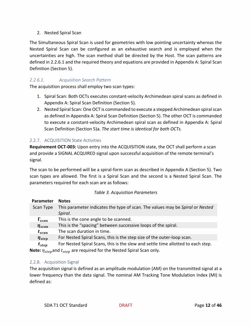
Table 3. Acquisition Parameters
Parameter Notes Scan Type This parameter indicates the type of scan. The values may be Spiral or Nested
Spiral. 𝚪𝚪𝒔𝒔𝒔𝒔𝒔𝒔𝒔𝒔 This is the cone angle to be scanned. 𝜼𝜼𝒔𝒔𝒔𝒔𝒔𝒔𝒔𝒔 This is the “spacing” between successive loops of the spiral. 𝒕𝒕𝒔𝒔𝒔𝒔𝒔𝒔𝒔𝒔 The scan duration in time. 𝜼𝜼𝒔𝒔𝒕𝒕𝒔𝒔𝒔𝒔 For Nested Spiral Scans, this is the step size of the outer-loop scan. 𝒕𝒕𝒔𝒔𝒕𝒕𝒔𝒔𝒔𝒔 For Nested Spiral Scans, this is the slew and settle time allotted to each step.
Note: 𝜂𝜂𝑠𝑠𝑠𝑠𝑠𝑠𝑠𝑠and 𝑡𝑡𝑠𝑠𝑠𝑠𝑠𝑠𝑠𝑠 are required for the Nested Spiral Scan only.
2.2.8. Acquisition Signal The acquisition signal is defined as an amplitude modulation (AM) on the transmitted signal at a lower frequency than the data signal. The nominal AM Tracking Tone Modulation Index (MI) is defined as:

SDA T1 OCT Standard DRAFT Page 13 of 46
MI =(Pmax − Pmin)(Pmax + Pmin)
Requirement OCT-004: The OCT shall provide an amplitude modulation (AM) Acquisition Signal.
Requirement OCT-005: The OCT shall reference the amplitude of the Acquisition Signal to the minimum and maximum amplitude of the transmitted signal to the Modulation Index (MI).
Requirement OCT-006: The OCT’s Acquisition Signal shall be a sinusoid. The Sinusoidal Tone is a sine wave modulation at a specified frequency.
2.2.9. PAT Acquisition Time The acquisition time is the time between the START COMMAND signal and the successful spatial alignment such that the link is “established.” The link is established when the OCT is tracking and data are being transported across the link.
Cold start means the post-calibration acquisition of a remote terminal that has not yet been acquired.
Warm start means the post-calibration acquisition of a remote terminal that has been recently tracked by the OCT.
Recently, in this context, shall refer to the period of time for which the error in a recent Tracking Pointing Vector results in a Warm Start Uncertainty Cone.
Examples:
1. For a spacecraft, a warm start is the period since the last successful track for which there has been no maneuver by either the local or remote spacecraft and the propagation error of the Tracking Pointing Vector is sufficiently low so as to enable a significantly more rapid acquisition, typically improved by one or more orders-of-magnitude in acquisition time, when compared to a cold start.
2. For a spacecraft to aircraft, a cold start results when the trajectory of the aircraft changed since the Tracking Pointing Vector Epoch.
2.3. Modulation
Requirement OCT-007: The OCT shall support On-Off-Keying Non-Return-to-Zero (OOK-NRZ).
Requirement OCT-008: The OCT shall support M-Ary PPM (MPPM) for M ∈ {4, 8, 16, and 32} per CCSDS 142.0-B-1 [5].
2.4. Latency
The Receive Latency is defined as the duration of time from the first photon of a message arriving at the OCT to the last bit of that message exiting the OCT to the host spacecraft.

SDA T1 OCT Standard DRAFT Page 14 of 46
The Transmit Latency is defined as the time between delivery of the first Ethernet packet from the host spacecraft to the OCT and the transmission of the last packet to exit the plane of the aperture of the OCT.
2.5. Spectral Grid Definition
To permit operations of multiple communications channels through wavelength division multiplexing (WDM), the ITU-T G.694 [6] 100 Ghz channel will serve as the basis for SDA Optical Communications channels. This grid follows the ITU-T G.694.1 recommendation and is limited to the 44 channels in the optical C-Band (1530 nm to 1565 nm).
𝐹𝐹𝐶𝐶𝑠𝑠𝐶𝐶𝑠𝑠𝑠𝑠𝐶𝐶(n) = 193.1 𝑇𝑇𝑇𝑇𝑇𝑇 + 𝑛𝑛 × 100 𝐺𝐺𝑇𝑇𝑇𝑇
2.6. Transmit and Receive Wavelength
Table 4defines the transmit and receive wavelengths. Either channel may be used for send while the other is used for receive. The same channel may not be used simultaneously for send and receive.
Table 4. Channel definitions. Channel Number (n)
Frequency (THz) Wavelength (nm) Transceiver Codec User Data Rate (Gbps)
-1 193.1 1553.33 Direct Detect OOK-NRZ or M-ary PPM
SDA-2021A 0.25 ≤ x ≤ 2.5
20 195.1 1536.61 Direct Detect OOK-NRZ or M-ary PPM
SDA-2021A 0.25 ≤ x ≤ 2.5
2.7. Channel Selection
Requirement OCT-009: The Host shall be able to select the OCT’s transmit and receive wavelengths through software set and get commands.
2.8. Polarization
Requirement OCT-010: The OCT shall transmit Left-hand Circular Polarization (LHCP) optical signals, where the E-vector rotates counter-clockwise as viewed from the transmitter in the direction of propagation per [5].
Requirement OCT-011: OCTs shall receive signals from LCHP-transmitters.
Requirement OCT-012: The OCT’s irradiance levels shall be measured in the LHCP polarization state in the direction of propagation from transmitter to receiver.
Requirement OCT-013: The transmitter shall emit LHCP light with a tolerance of 23 dB or higher.
Requirement OCT-014: The transmitter shall provide an irradiance at the plane of the receive aperture at a range of 7500 km of up to 30 𝜇𝜇𝜇𝜇/𝑚𝑚2.

SDA T1 OCT Standard DRAFT Page 15 of 46
3. Layer 2 - Synchronization and Channel Coding Layer
3.1. Protocols
SDA intends to leverage the availability of commercial off-the-shelf (COTS) components and intellectual property (IP).
Table 5 defines the protocol names, ID, and modulation type. These protocols are described in this section. The protocol class is referred to as the SDA-LDPC.
Table 5
Protocol Protocol ID Modulation 2021A-OOK-NRZ-LDPC SDA-2021A OOK-NRZ 2021B-M-PPM-LDPC SDA-2021B M-Ary PPM
Requirement OCT-015: The OCT shall implement the SDA-2021A and SDA-2021B Protocols.
3.2. Re-Programming
Requirement OCT-016: Layers 1 and 2 shall be re-programmable. During reprogramming, the transmission of data may be interrupted.
3.3. Effective Data Rate and Protocols
Protocols and the applicable data rates are shown in Table 6.
Note: The data rates are approximate and are defined in the associated reference documents.
Table 6
Protocol ID and Rate Designator (format: <Protocol ID>-<Rate ID>) User Data Rate SDA-2021A-0 78.125 Mbps SDA-2021A-1 156.25 Mbps SDA-2021A-2 312.5 Mbps SDA-2021A-3 625 Mbps SDA-2021A-4 1.25 Gbps SDA-2021A-5 2.5 Gbps SDA-2021B-0 78.125 Mbps SDA-2021B-1 156.25 Mbps SDA-2021B-2 312.5 Mbps SDA-2021B-3 625 Mbps SDA-2021B-4 1.25 Gbps SDA-2021B-5 2.5 Gbps

SDA T1 OCT Standard DRAFT Page 16 of 46
Requirement OCT-017: The OCT shall be capable of transmitting and receiving in full duplex at the user data rates defined in Table 6.
3.4. Framing, Coding, and Encapsulation
3.4.1. Frame Structure The structure of the OTA frames used by the OCT modem is shown in Table 7.
Requirement OCT-018: All OTA frames in the OCT modem shall be constructed identically: a preamble sequence concatenated with a fixed-length header followed by data bits (fixed size, plus CRC) then a variable number of parity bits. The number of parity bits is governed by the configured codec and code rate (Section 3.4.3.1).
Table 7: Modem Frame Format
Field # of bits Comments Preamble 64 Preamble: 64’53225b1d0d73df03.
The MSB (64th) bit is transmitted first followed in order down to the LSB (1st).
Header 948 See Section 3.4.1.2. Payload - Data 8160 Information payload. Fixed size (8160 bits)
for all modem frame configurations. Payload - CRC 32 Cyclic redundancy check covering payload
bits. Payload - Parity variable Number of parity bits depends on the
configured payload FEC codec and code rate.
Requirement OCT-019: Transmission of modem frames shall be synchronous with no pauses between frames and no pauses between any of the bits comprising the frame components in Table 7.
3.4.1.1. Preamble Sequence Requirement OCT-020: Every frame shall start with a Preamble Sequence (PS), which is used by the receive modem for frame synchronization.
Requirement OCT-021: The preamble sequence shall be identical for all OCT modem frames and takes the value shown in Table 7.
3.4.1.2. Header Requirement OCT-022: A modem header shall be present in every modem frame immediately following the preamble sequence.
Requirement OCT-023: The OCT modem frame header shall have these characteristics:
• Modem headers are a fixed size (i.e., number of coded bits) for all configurations.

SDA T1 OCT Standard DRAFT Page 17 of 46
• Modem headers are protected by a strong Forward Error Correction (FEC) scheme with a fixed code rate (Section 3.4.2.2)
• The payload of the modem header is protected by a CRC-16 (Section 3.4.2.1).
The contents of the OCT modem frame header are detailed in Section 3.4.3.
3.4.1.3. Payload This section describes how payload (information) bits are encoded into the OCT modem frame.
3.4.1.3.1. Data Bits Requirement OCT-024: All modem frames shall carry a payload of exactly 8160 information bits.
3.4.1.3.2. CRC-32 Requirement OCT-025: All modem frames shall protect the integrity of the payload information bits with a 32-bit CRC (Section 3.4.2.1).
3.4.1.3.3. Parity Bits The OCT modem features strong payload FEC.
Requirement OCT-026: The payload shall implement FEC with the following properties:
• Systematic FEC (i.e., a copy of the payload data bits appears in the encoded payload codeword).
• Zero or more parity bits.
The number of parity bits is a function of the codec and code rate selection (Table 10) and can be as few as zero bits (uncoded) up to as many as 8192 bits (LDPC, code rate 1/2).
The payload FEC is a systematic, irregular low-density parity check (LDPC) code with a weight-one circulant structure and circulant size of 64.
3.4.1.4. Scrambling Requirement OCT-027: All portions of the modem frame, except for the Preamble Sequence, shall be scrambled prior to transmission as described herein.
The scrambling sequence is a maximal length sequence (equivalently referred to as an 𝑚𝑚-sequence) generated by the primitive polynomial
𝑝𝑝(𝑥𝑥) = 1 + 𝑥𝑥14 + 𝑥𝑥15.
The sequence can be generated by a linear-feedback shift-register circuit. A reference implementation producing the correct scrambling sequence is shown in Figure 2. The following describe the sequence employed in the generation of the scrambling sequence:
• The shift-register is initialized to [𝑥𝑥0, 𝑥𝑥1, … , 𝑥𝑥14] = [000011011011100] at the start of every frame.

SDA T1 OCT Standard DRAFT Page 18 of 46
• The shift register circuit is clocked once per transmitted bit for the totality of the frame. However, scrambling is not applied to the Preamble Sequence (initial 64 bits of the frame). Beginning with the first bit after the Preamble Sequence, frame bits 𝑓𝑓𝑘𝑘 are exclusive-or with the scrambling sequence 𝑠𝑠𝑘𝑘.
• Scrambled sequence 𝑦𝑦𝑘𝑘 = 𝑓𝑓𝑘𝑘 + 𝑠𝑠𝑘𝑘 is transmitted over the air, where “addition” is over GF(2). Binary addition on GF(2) is mathematically equivalent to an exclusive OR (XOR) operation.
The circuit shown in Figure 2 generates a scrambling sequence with period 215 − 1 = 32767 bits.
Figure 2: Generation of Scrambling Sequence
The modem starts preamble sequence generation at the first bit of the frame with the first 64 bits of the preamble sequence not applied (these cover the preamble sequence, which is not scrambled).
The same scrambling seed is applied at the start of every modem frame.
Figure 3 depicts the steps for frame generation.
Figure 3: OCT modem Frame Construction
All frame types (Section 3.4.4) are constructed identically.
3.4.2. Error Control Coding Requirement OCT-028: All OCT modem frames shall feature strong error control coding as described herein.

SDA T1 OCT Standard DRAFT Page 19 of 46
The error control coding features the following:
• Information bits are protected by CRC’s (Section 3.4.2.1, header: 16 bits, payload: 32 bits)
• Fixed-rate convolutional code (CC) for the frame Header (Section 3.4.2.2)
• Variable-rate low-density parity check code (LDPC) for the frame Payload (Section 3.4.2.3).
This section details the encoders for all the error control codes.
3.4.2.1. CRC Two CRC’s are required to generate the modem frame: a CRC-16 protects the Header while a CRC-32 protects the payload. A functional description of a generic 𝐿𝐿-bit CRC encoder circuit is shown in Figure 4. The circuit consists of an 𝐿𝐿-bit register (𝐿𝐿 = 16 for CRC-16 and 𝐿𝐿 = 32 for CRC-32). The connection polynomials (i.e., values 𝑔𝑔𝑘𝑘) are defined in Table 8 for each of the two CRC’s required to create the modem frame.
Figure 4: 𝐿𝐿-bit CRC Calculation Circuit
Calculation of the CRC for a block of 𝑘𝑘 payload bits:
• Initialize the 𝐿𝐿-bit encoder register state to zero at the start of each new CRC calculation • Clock in the 𝑘𝑘 payload bits with switches 𝑆𝑆1 and 𝑆𝑆2 both in the down position • After the last payload bit has been loaded the encoder register contains the 𝐿𝐿-bit CRC
value. It can be clocked-out with switches 𝑆𝑆1 and 𝑆𝑆2 in the up position.
Table 8: CRC Polynomials
Location Length Polynomial Source Frame Header 16 bits 𝑔𝑔(𝑥𝑥) = 𝑥𝑥16 + 𝑥𝑥12 + 𝑥𝑥5 + 1 CCITT X.25

SDA T1 OCT Standard DRAFT Page 20 of 46
Frame Payload 32 bits
𝑔𝑔(𝑥𝑥) = 𝑥𝑥32 + 𝑥𝑥26 + 𝑥𝑥23 + 𝑥𝑥22+ 𝑥𝑥16 + 𝑥𝑥12 + 𝑥𝑥11+ 𝑥𝑥10 + 𝑥𝑥8 + 𝑥𝑥7+ 𝑥𝑥5 + 𝑥𝑥4 + 𝑥𝑥2 + 𝑥𝑥+ 1
ANSI, IEEE 802.3, ITU-T V.42
3.4.2.2. Header FEC The modem header payload is encoded by a non-systematic constraint length 7, rate 1/6 convolutional code prior to transmission. Generator polynomials for this (7, 1/6) code are listed in Table 9.
Table 9: Rate 1/6 Convolutional Code for Frame Header
Coded bit Generator Polynomial (octal)
0 0175 1 0171 2 0151 3 0133 4 0127 5 0117
The convolutional encoder is initialized at the start of every new Header to state zero. Header payload enters the encoder MSB first up to the end of the 16-bit CRC then flushed with 8 zero-valued bits to return the encoder state to zero.
The total size of the encoded header as transmitted “over the air” is 158 × 6 = 948 bits.
3.4.2.3. Payload FEC All OCT modem frames carry an 8160-bit payload per frame which is protected by both a CRC-32 and by variable code rate strong FEC. This includes:
• Low-Density Parity Check Code (LDPC) • Systematic Encoder • Variable code rate from 𝑅𝑅 = 8
9 to 𝑅𝑅 = 1
2.
To facilitate efficient implementation of the LDPC codec on FPGA platforms the LDPC code is designed with these structural properties:
• Single weight circulant structure • Circulant size 64 • Irregular
Circulant tables describing the LPDC code are in Section 3.5.

SDA T1 OCT Standard DRAFT Page 21 of 46
3.4.3. Frame Header This section details the contents of the OCT modem header. The modem header implements the signaling required for implementation of the modem features.
3.4.3.1. Header Fields The frame Header fields are listed in Table 10. A single Header is present in every modem frame.
Table 10: Frame Header Fields
3.4.3.2. Automatic Repeat Request (ARQ) Header fields supporting implementation of the Automatic Repeat Request modem feature are grouped as the “ARQ” fields in Table 10. The ARQ configuration parameters shall remain static for the duration of a session. The ARQ configuration may only be changed prior to the onset of acquisition. ARQ operation is not expected to be used for crosslinks. More details can be provided if needed.
Function Field Bits Description
ARQ TXFN 16 Sequence number of this (outgoing) TX frame ACK_START_FN 16 Sequence number of first ACK
ACK_SPAN 3 ACK/NAK applies to 2^(ACK_SPAN) consecutive RXFN000-101: legal values (ACK_SPAN=1, … ACK_SPAN=32)110-111: Reserved
ACK_valid 1 0: no ACK/NAK in this frame 1: ACK/NAK valid
ACK 1 0: NAK for RXFN and 2^(ACK_SPAN) consecutive RXFN1: ACK for RXFN and 2^(ACK_SPAN) consecutive RXFN
TX_NUM 3 transmission attempt (0=initial, max re-TX=7)
FEC PL_RATE 2 0: 1024 parity bits1: 2048 parity bits2: 4096 parity bits3: 8192 parity bits
MAC FRAME_TYPE 2 0: IDLE 1: DATA 2: MGMT 3: reservedpseudo-range TX_TS 40 TX time-stamp (frame egress)Fast Control Channel FCCH_OPCODE 4 time-multiplexed control signalling FCCH_PL 48 Payload contents depends on FCCH_TYPECRC CRC-16 16Zero-tail ZT 6 Flush convolutional code state to zeroTotal 158

SDA T1 OCT Standard DRAFT Page 22 of 46
3.4.3.3. Payload FEC The OCT modem features strong payload FEC (Section 3.4.2.3).
The payload FEC code rate is computed 𝑅𝑅 = 8192/(8192 + nparity)). Payload code rates are tabulated in Table 11.
Table 11: Payload FEC Code Rates (LDPC)
PL_RATE Number of parity bits
Payload Code Rate (LDPC)
0 1024 8/9 1 2048 4/5 2 4096 2/3 3 8192 1/2
3.4.3.4. Range Measurement Requirement OCT-029: The OCT modem shall provide an integrated ranging capability when enabled.
3.4.3.4.1. Timestamps Requirement OCT-030: The TX PHY shall apply a timestamp in the header of every modem frame (TX_TS field, Table 10). The implementation shall reference the applied timestamp to the egress point of the modem frame (crossing the plane of the aperture).
Requirement OCT-031: The RX PHY shall similarly record a timestamp of the ingress of every modem frame (RX_TS). The implementation shall reference the recorded timestamp to the ingress point of the modem frame (crossing the plane of the aperture).
3.4.3.5. Fast Control Channel (FCCH) Requirement OCT-032: The OCT modem frame shall provide an embedded fast control channel (FCCH) as described herein.
The FCCH provides a low-rate channel with reserved bandwidth for robust, low-latency transport of short messages between OCT terminals. The FCCH enjoys the benefit of both error detection (via the Header CRC) and strong error correction (via the Header FEC) by virtue of residing in the frame Header. No ARQ is provided for the FCCH channel.

SDA T1 OCT Standard DRAFT Page 23 of 46
The FCCH physical channel is time-multiplexed:
• FCCH_OPCODE (4 bits): opcode which determines the format of the FCCH payload • FCCH_PL (48 bits): payload bits.
A single FCCH is transmitted and received in every frame and can be valid for every FRAME_TYPE (Table 10 and Section 3.4.4).
The higher layers of the modem divide the capacity of the FCCH physical channel into multiple logical channels through time-multiplexing. The effective average data rate of these logical channels is a function of the payload FEC, baud rate, and the frequency of which the logical channel is scheduled by the modem higher layers. The FCCH logical channels are defined in Table 12. If no data is waiting for transport, the FCCH opcode 1111 shall be specified. In this case the FCCH payload bits shall be all ones. Payload values for Reserved opcodes must be all zeros.
New types of FCCH can be defined as needed. Details of the FCCH messages can be provided.
Table 12: FCCH Logical Channels
Description FCCH _TYPE Opcode (4 bits)
Payload
Capabilities OCT_CAPABILITIES 0000 Link Adaptation LAPC_REPORT 0001
Reserved N/A 0011-1110 N/A Not Present N/A 1111
3.4.4. Special Frames Requirement OCT-033: The FRAME_TYPE field of the frame Header (Table 10) shall signal the type of modem frame as described herein.
This section defines the frame types and their intended usage on the optical interface. Features signaled through the frame header are available in all frame types.
3.4.4.1. IDLE Frames By design the modem always transmits frames with no gap between adjacent frames. In the case that data is not available for transmission the modem shall insert consecutive IDLE frames into the transmitted stream until other types of traffic frames become available. There shall not be a gap between frames under any circumstance.
3.4.4.1.1. Header Construction Modem IDLE frames are signaled in the frame header by field FRAME_TYPE=00 (Table 10).
Modem IDLE frame headers are otherwise identical to normal data frame headers with the exception that the TXFN field in an IDLE frame header is always equal to the master TXFN counter.
SDA T1 OCT Standard DRAFT Page 24 of 46
3.4.4.1.2. Payload Construction Modem IDLE frames are subject to the same payload FEC and are protected by the same CRC-32 as the data frames.
The information payload in IDLE frames is constructed as a pseudo-random binary sequence (PRBS) using the same generator as the frame scrambler (Figure 2) except with its initial seed equal to the value of the TXFN field in the frame header (Table 10). If the value of TXFN used to seed the PRBS is equal to the state of the frame scrambler, the seed shall be over-written with a TBD-1 value for its seed.
The size of the IDLE information payload is the same as for data frames.
3.4.4.2. MGMT Frames The MGMT frame type is provided for management frames. These frames are used for inter-OCT communications.
3.4.4.2.1. Header Construction Modem MGMT frames are signaled in the frame header by field FRAME_TYPE=10 (Table 10).
3.4.4.2.2. Payload Construction Modem MGMT frames are subject to the same payload FEC and are protected by the same CRC-32 as the data frames.
The size of the MGMT information payload is the same as for data frames.
3.4.5. Ethernet Encapsulation
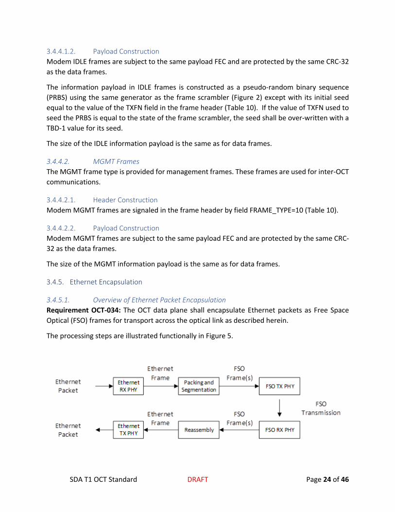
3.4.5.1. Overview of Ethernet Packet Encapsulation Requirement OCT-034: The OCT data plane shall encapsulate Ethernet packets as Free Space Optical (FSO) frames for transport across the optical link as described herein.
The processing steps are illustrated functionally in Figure 5.

SDA T1 OCT Standard DRAFT Page 25 of 46
Figure 5: Ethernet Encapsulation
This scheme permits the OCT to carry virtually any form of Ethernet traffic transparently between a pair of optical terminals. The presence of the OCT is largely transparent to the endpoints.
3.4.5.1.1. Ethernet Packet Handling On ingress to the modem, the Ethernet frame shall be extracted from every Ethernet packet by stripping the Preamble and the Start Frame Delimiter (SFD) from the packet. The Ethernet frames must be queued to the Packing and Segmentation block for encapsulation as FSO frames.
On egress from the modem, the TX Ethernet PHY must construct Ethernet packets from the received (reconstructed) Ethernet frames by pre-pending for each frame the Ethernet Preamble and Start Frame Delimiter (SFD) and appending an appropriate Interpacket Gap (IPG). The reconstructed Ethernet packet must be emitted by the Ethernet PHY.
3.4.5.1.2. Packing and Segmentation The Packing and Segmentation operation (Figure 5) must perform the following functions in the TX PHY of the optical terminal:
• Segments large Ethernet frames into one or more FSO frames (as needed) • Packs small Ethernet frames into FSO frames
The implementation of the Packing and Segmentation operation must preserve the ingress order of Ethernet packets.
3.4.5.1.3. FSO Frame Payload Format This section defines how the output of the Packing and Segmentation operation is formatted in the payload section of an FSO DATA Frame. The structure is illustrated logically in Figure 6. The bytes must be written into the payload FEC frame in physical byte order. The bytes must be consecutive, per word in Figure 6, with the lower 8 bits (0 to 7) denoting the first byte, followed by the next grouping of bytes up to the upper set of 8 bits (24 to 31) denoting the fourth byte. The numbering of bytes for the purpose of defining their ordering entering the payload FEC must count up naturally for each 32-bit word in Figure 6.

SDA T1 OCT Standard DRAFT Page 26 of 46
FSO Packet Header - N
FSO Payload HeaderFSO Packet Header -1FSO Packet Payload -1
FSO Packet Payload - N
pad to zero
CRC-32
Encapsulated Ethernet
Frame
Encapsulated Ethernet Frame(s)
One or more FSO Packet Headers per FSO Frame
One FSO Frame(8192 bits)
CRC covering the full FSO Frame
One Payload Header per FSO Frame
Unused space (if any) padded to zero
Bit 0Bit 31
word 0
word 1
word 255
Figure 6: FSO Payload Frame Format
The FSO Payload and FSO Frame headers split Ethernet frame payloads across multiple frames, enabling efficient packing of Ethernet frames into FSO frames.
There must not be any zero-pad space except at the end of the FSO frame as illustrated in Figure 6.
Note that the CRC-32 described in Figure 6 is the same CRC-32 previously described in and is repeated here for clarity.
3.4.5.1.4. FSO Payload and Packet Headers Requirement OCT-035: Every FSO frame shall start with an FSO Payload Header.
Requirement OCT-036: There shall be exactly one FSO Payload Header (32 bits) per FSO frame.
Requirement OCT-037: The contents of the FSO frame and packet headers shall follow the definition presented in Table 13.
Table 13: FSO Payload and Packet Headers
Field bit numbers
#bits
FSO Payload Header (32 bits)
0xAB 31:24 8
seq_num 23:14 10
Length 13:0 14

SDA T1 OCT Standard DRAFT Page 27 of 46
FSO Packet Header (32 bits)
0xCDEF 31:16 16
reserved 15:14 2
Length 13:0 14
FSO Payload Header:
The FSO Payload Header is constructed as an 8-bit magic number (0xAB) followed by a 10-bit sequence number and a 14-bit length field. Sequence numbers shall increment sequentially for every DATA frame and wrap naturally around zero. The sequence number referenced in Table 13 is unrelated to the modem’s ARQ signaling in Table 10.
The system must be capable of splitting an encapsulated Ethernet frame payload across multiple FSO frames. The FSO Payload Header length field shall have a non-zero value only when an Ethernet frame is segmented across the preceding and current FSO DATA frames, signaling the length of the preceding encapsulated packet remaining. Otherwise, the length field shall be zero.
FSO Packet Header:
The FSO packet header (Table 13) shall signal encapsulation of an Ethernet frame. The header shall be constructed as a 16-bit magic number (0xCDEF) followed by two reserved bits (0b00) and a 14-bit length field. The length field shall signal the number of payload bytes to follow where the length field excludes the length of the packet header regardless of whether the Ethernet frame is segmented into the following FSO frame.
3.4.5.1.5. Ethernet Byte Ordering, Padding, and CRC FSO packet headers are aligned to a 32-bit boundary. If the encapsulated Ethernet frame length is not a multiple of 4 bytes, the implementation must pad the remaining unused space in the FSO frame with zeros.
Ethernet frame payload bytes shall be written into the FSO frame (Figure 6) in natural (ascending) order with the first ingress byte of the Ethernet frame written into the first word after the FSO Packet header starting at byte 0 (bit positions [7:0]), incrementing up through byte 3 (bit positions [31-24]), then incrementing to the next word in the FSO frame. Unused bytes in the FSO frame shall be padded with zeros.
An example of the byte ordering for the encapsulation of a hypothetical Ethernet frame of length 𝑛𝑛 bytes is illustrated in Table 14. The Payload Header (Table 13) is written into FSO frame word 0. In this example, suppose that there is no Ethernet frame continued from a preceding FSO frame. Then a Packet Header is written into FSO frame word 1. This marks the start of the encapsulated Ethernet frame bytes. The bytes of the Ethernet frame (ETH_Byte_0, …, ETH_Byte_n) are written sequentially in the natural (ascending) byte order in which they were

SDA T1 OCT Standard DRAFT Page 28 of 46
received starting in the first FSO word following the Packet Header until either the entire Ethernet frame is written or the available space in the FSO frame is consumed.
Table 14: Ethernet Frame Byte Ordering into FSO Logical Frame
The implementation shall be capable of emitting FSO frames with partially packed Ethernet frames. In the case that the Ethernet frame is segmented, the Ethernet bytes are continued into the immediately following FSO DATA frame with the appropriate signaling in the FSO Payload header as previously described (Section 3.4.5.1.4).
Every FSO frame shall end with a 32-bit CRC. In all cases, the CRC shall cover the entire frame, including any portions of the frame padded with zeros.
3.4.5.1.6. Reassembly of Ethernet Frames The implementation’s optical RX PHY shall reconstruct the sequence of ingress Ethernet packets from the (packed) FSO frames received from the far-end terminal. The frames shall be transmitted on its egress Ethernet in the same order and with the same packet sizes as received by the Ethernet RX PHY on its ingress Ethernet.
The Reassembly process (the Reassembly Block in Figure 5) shall implement the following:
• If an FSO frame is received with a sequence number skip, any Ethernet packet whose payload was not complete shall be discarded. The received FSO frame with the skipped sequence number shall be retained only if the length field of its FSO frame header is zero. Any FSO packet headers following the end of the first partial packet in the FSO frame are valid.
• Any FSO frame whose magic number in its FSO Frame Header (Table 13) is incorrect shall be discarded entirely.
• Any FSO Packet Header within any FSO frame (Table 13) whose magic number is incorrect shall be discarded.
• Any FSO Packet Header whose length field is inconsistent shall be discarded.
FSO word number contents 31-24 23-16 15-8 7-0word 0 Payload Headerword 1 Packet Headerword 2 Ethernet bytes ETH_Byte_3 ETH_Byte_2 ETH_Byte_1 ETH_Byte_0
word M Zero_Pad Zero_Pad ETH_Byte_n-1 ETH_Byte_n-2
AB[31:24], seq_num[23:14], length[13:0]CDEF[31:18], reserved [17:16], length[13:0]
…

SDA T1 OCT Standard DRAFT Page 29 of 46
FSO Packet Header - N
FSO Payload HeaderFSO Packet Header -1FSO Packet Payload -1
FSO Packet Payload - N
pad to zero
CRC-32
Encapsulated Ethernet
Frame
Encapsulated Ethernet Frame(s)
One or more FSO Packet Headers per FSO Frame
One FSO Frame(8192 bits)
CRC covering the full FSO Frame
One Payload Header per FSO Frame
Unused space (if any) padded to zero
Bit 0Bit 31
word 0
word 1
word 255
Figure 7: FSO Payload Frame Format
3.4.6. Effective Data Rate The effective data rates for the primary OCT modem frame configurations are summarized in Table 15. For brevity, the data rates are tabulated only for the extreme settings of payload FEC (R=8/9 and R=1/2) with the LDPC codec.

SDA T1 OCT Standard DRAFT Page 30 of 46
Table 15: Effective Data Rates for Frame Configurations
Baud rate (Msps) Line Code Baud Time
(ns) Frame Duration (µsec) Payload Data Rate (Mbps) FCCH Data Rate (Mbps) R=8/9 R=1/2 R=8/9 R=1/2 R=8/9 R=1/2
2500 None 0.4 4.09 6.96 1994.52 1172.68 11.73 6.90 1250
Manchester
0.8 8.18 13.92 997.26 586.34 5.87 3.45 625 1.6 16.36 27.83 498.63 293.17 2.93 1.72
312.5 3.2 32.73 55.67 249.32 146.59 1.47 0.86 156.25 6.4 65.46 111.33 124.66 73.29 0.73 0.43 78.125 12.8 130.92 222.67 62.33 36.65 0.37 0.22
The quoted data rates account for all sources of overhead including preamble, header, CRC’s, and FEC.

20210601-001 DRAFT Page 31 of 46
3.5. Circulant Tables for Payload LDPC Code
The payload FEC features a low-density parity check (LDPC) code with performance near the Shannon capacity limit in additive white Gaussian noise. The key attributes of the payload LDPC code are summarized in Table 16.
Table 16: LDPC Code Properties
LDPC Code Family Quasi-cyclic
Parity Check Matrix (PCM)
Single-weight circulant
Circulant size 64
Irregular structure
Block size 8192 information bits
Rate R=1/2 (lowest), number of non-zero circulants = 1408
R=8/9 (highest), number of non-zero circulants = 512
Encoder Algorithm Pre-computed generator matrix (G) G is dense but has a quasi-cyclic structure on each of its 𝑆𝑆 × 𝑆𝑆 tiles (𝑆𝑆 = 64)
Decoder Algorithm Normalized min-sum algorithm
Up to 10 iterations, early-exit feature when syndrome is satisfied
3.5.1. LDPC Code Tables The payload LDPC code is quasi-cyclic with a single-weight circulant size of 𝑆𝑆 = 64. Per the specifications in Table 16, the code’s parity check matrix has these properties:
• Number of information bits: 8192 • Maximum number of parity bits: 8192 • Circulant size: 64
The payload FEC code has a single-weight circulant structure and can compactly be represented by a table of its circulants, requiring a matrix with
�8192
64 � 𝑟𝑟𝑟𝑟𝑟𝑟𝑠𝑠 × �16384
64 � 𝑐𝑐𝑟𝑟𝑐𝑐𝑐𝑐𝑚𝑚𝑛𝑛𝑠𝑠
20210601-001 DRAFT Page 32 of 46
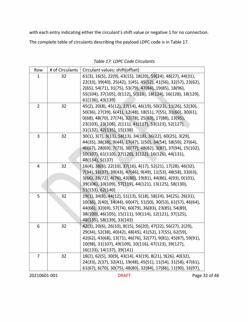
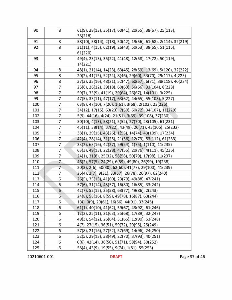
with each entry indicating either the circulant’s shift value or negative 1 for no connection.
The complete table of circulants describing the payload LDPC code is in Table 17.
Table 17: LDPC Code Circulants
Row # of Circulants Circulant values: shift(offset) 1 32 61(3), 16(5), 22(9), 43(15), 18(20), 59(24), 48(27), 44(31),
22(33), 39(40), 25(42), 1(45), 45(52), 41(56), 32(57), 23(62), 2(65), 54(71), 31(75), 53(79), 47(84), 19(85), 18(96), 55(104), 37(105), 0(112), 5(118), 18(124), 16(128), 18(129), 61(136), 43(139)
2 32 45(2), 20(8), 45(12), 27(14), 46(19), 50(23), 11(26), 52(30), 50(36), 27(39), 6(41), 12(48), 18(51), 7(55), 31(60), 30(61), 0(68), 48(70), 27(74), 32(78), 25(83), 17(88), 13(95), 23(103), 23(108), 2(111), 41(117), 53(123), 52(127), 31(132), 42(135), 15(138)
3 32 30(1), 3(7), 3(11), 58(13), 34(18), 36(22), 60(25), 3(29), 44(35), 38(38), 9(44), 17(47), 1(50), 34(54), 58(59), 27(64), 40(67), 28(69), 7(73), 38(77), 48(82), 3(87), 37(94), 15(102), 10(107), 61(110), 27(120), 1(122), 16(126), 44(131), 48(134), 5(137)
4 32 16(4), 38(6), 22(10), 37(16), 4(17), 52(21), 17(28), 46(32), 7(34), 16(37), 39(43), 47(46), 9(49), 11(53), 48(58), 33(63), 3(66), 28(72), 4(76), 43(80), 19(81), 44(86), 4(93), 0(101), 39(106), 10(109), 57(119), 44(121), 13(125), 58(130), 51(133), 62(140)
5 32 19(1), 34(8), 44(12), 51(13), 5(18), 58(24), 34(25), 26(31), 10(36), 2(40), 14(44), 60(47), 51(50), 30(53), 61(57), 46(64), 44(66), 32(69), 57(74), 60(79), 36(83), 23(85), 54(89), 38(100), 46(105), 15(111), 59(114), 12(121), 37(125), 48(135), 58(139), 33(143)
6 32 42(3), 20(6), 26(10), 8(15), 56(20), 47(22), 56(27), 2(29), 29(34), 52(38), 40(42), 48(45), 41(52), 17(55), 62(59), 42(62), 43(68), 13(71), 46(76), 32(77), 9(81), 45(87), 59(91), 10(98), 31(107), 49(109), 10(116), 47(123), 39(127), 16(133), 14(137), 39(141)
7 32 18(2), 62(5), 30(9), 43(14), 43(19), 8(21), 9(26), 40(32), 24(33), 2(37), 32(41), 19(48), 45(51), 11(54), 31(58), 47(61), 61(67), 6(70), 30(75), 48(80), 32(84), 17(86), 11(90), 16(97),

20210601-001 DRAFT Page 33 of 46
30(106), 55(112), 44(115), 17(122), 36(126), 12(136), 42(140), 33(144)
8 32 59(4), 62(7), 63(10), 40(13), 48(20), 8(22), 0(28), 39(30), 30(36), 34(39), 10(43), 29(47), 50(52), 61(56), 14(59), 63(63), 47(68), 36(71), 63(73), 60(78), 11(85), 12(92), 22(96), 45(99), 33(101), 29(111), 4(114), 19(119), 33(125), 63(132), 27(138), 41(141)
9 32 28(1), 42(8), 9(11), 24(14), 9(17), 36(23), 14(25), 14(31), 19(33), 31(40), 40(44), 26(48), 15(49), 9(53), 46(60), 24(64), 54(65), 38(72), 12(74), 14(79), 7(86), 30(89), 47(93), 63(100), 6(102), 30(112), 37(115), 42(120), 1(126), 1(129), 50(139), 9(142)
10 32 47(3), 62(6), 41(9), 30(16), 52(19), 7(21), 31(27), 13(29), 7(35), 33(38), 28(42), 30(46), 22(51), 24(55), 39(58), 44(62), 20(67), 44(70), 39(76), 15(77), 46(88), 7(91), 38(95), 13(98), 57(104), 46(110), 3(113), 28(118), 40(128), 45(131), 44(137), 6(144)
11 32 63(2), 49(5), 50(12), 48(15), 24(18), 30(24), 53(26), 5(32), 41(34), 29(37), 51(41), 7(45), 11(50), 43(54), 50(57), 4(61), 53(66), 39(69), 40(75), 38(80), 49(87), 18(90), 2(94), 53(97), 34(103), 11(109), 18(116), 16(117), 38(127), 38(130), 24(140), 41(143)
12 32 61(4), 57(7), 17(11), 53(16), 43(17), 9(23), 9(28), 43(30), 62(35), 11(39), 16(43), 48(46), 46(49), 35(56), 49(60), 50(63), 4(65), 21(72), 20(73), 3(78), 42(82), 60(88), 9(92), 25(99), 44(108), 2(110), 57(113), 19(124), 26(128), 43(134), 13(138), 33(142)
13 32 26(1), 14(8), 47(9), 36(14), 3(20), 13(23), 4(27), 61(29), 46(36), 61(38), 20(44), 55(48), 5(51), 5(53), 39(59), 13(64), 37(68), 57(71), 29(76), 10(80), 48(83), 20(91), 48(95), 44(97), 16(102), 3(107), 15(114), 42(117), 45(121), 49(132), 31(133), 3(144)
14 32 38(3), 15(6), 42(11), 17(16), 14(18), 15(21), 2(25), 5(31), 42(34), 62(40), 22(42), 2(46), 41(49), 51(55), 30(57), 40(62), 48(66), 38(69), 30(74), 13(78), 56(81), 44(89), 0(93), 54(99), 31(104), 53(105), 50(116), 9(119), 9(123), 57(130), 30(135), 53(142)
15 32 30(4), 52(7), 4(12), 21(13), 39(19), 60(22), 37(26), 8(32), 24(35), 44(37), 9(43), 51(47), 15(50), 38(56), 44(58), 8(63), 51(67), 46(70), 25(75), 41(79), 6(82), 63(90), 27(94),

20210601-001 DRAFT Page 34 of 46
44(100), 40(101), 23(106), 27(113), 47(120), 54(124), 19(131), 6(136), 43(143)
16 32 30(2), 6(5), 59(10), 58(15), 26(17), 14(24), 30(28), 34(30), 17(33), 22(39), 59(41), 51(45), 17(52), 44(54), 54(60), 20(61), 26(65), 63(72), 2(73), 7(77), 55(84), 2(92), 6(96), 31(98), 27(103), 45(108), 33(115), 62(118), 53(122), 38(129), 35(134), 22(141)
17 10 22(12), 10(16), 24(21), 0(41), 14(51), 30(70), 48(90), 53(107), 61(117), 0(149)
18 10 36(6), 24(12), 9(18), 35(37), 4(62), 46(65), 29(85), 54(101), 50(114), 4(146)
19 10 30(7), 6(9), 10(19), 45(38), 4(63), 58(66), 29(86), 59(102), 60(115), 12(147)
20 10 44(8), 6(10), 47(20), 18(39), 36(64), 60(67), 26(87), 29(103), 38(116), 40(148)
21 10 9(5), 2(11), 60(17), 63(40), 8(61), 25(68), 23(88), 35(104), 41(113), 38(145)
22 10 54(9), 20(13), 30(22), 36(42), 22(52), 34(71), 38(91), 11(108), 8(118), 21(150)
23 10 27(10), 41(14), 35(23), 25(43), 10(49), 4(72), 1(92), 33(105), 39(119), 45(151)
24 10 27(11), 39(15), 51(24), 1(44), 8(50), 31(69), 62(89), 14(106), 48(120), 5(152)
25 10 6(3), 44(14), 14(27), 8(45), 37(55), 50(75), 33(94), 26(109), 36(124), 24(153)
26 10 21(4), 25(15), 37(28), 39(46), 40(56), 43(76), 2(95), 14(110), 46(121), 21(154)
27 10 49(1), 51(16), 18(25), 53(47), 22(53), 35(73), 10(96), 31(111), 38(122), 27(155)
28 10 50(2), 19(13), 30(26), 49(48), 61(54), 8(74), 50(93), 28(112), 39(123), 19(156)
29 10 63(4), 5(8), 58(30), 48(35), 38(59), 61(80), 60(82), 24(98), 18(127), 25(157)
30 10 35(1), 43(5), 45(31), 57(36), 57(60), 14(77), 40(83), 34(99), 36(128), 22(158)
31 10 27(2), 46(6), 37(32), 38(33), 17(57), 16(78), 7(84), 43(100), 25(125), 22(159)
32 10 23(3), 43(7), 22(29), 47(34), 40(58), 5(79), 63(81), 61(97), 58(126), 52(160)

20210601-001 DRAFT Page 35 of 46
33 9 60(10), 5(16), 61(25), 36(43), 38(61), 13(66), 17(108), 62(123), 37(161)
34 9 36(11), 5(13), 20(26), 49(44), 60(62), 44(67), 8(105), 6(124), 31(162)
35 9 40(12), 30(14), 9(27), 34(41), 27(63), 18(68), 37(106), 34(121), 2(163)
36 9 52(9), 7(15), 55(28), 30(42), 43(64), 61(65), 52(107), 11(122), 20(164)
37 9 29(2), 29(14), 34(31), 27(45), 1(51), 16(70), 41(111), 50(128), 17(165)
38 9 46(3), 26(15), 11(32), 58(46), 4(52), 28(71), 54(112), 55(125), 24(166)
39 9 29(4), 45(16), 62(29), 5(47), 58(49), 50(72), 6(109), 30(126), 23(167)
40 9 51(1), 34(13), 15(30), 42(48), 38(50), 54(69), 44(110), 6(127), 2(168)
41 9 32(4), 45(8), 52(20), 26(36), 15(54), 18(73), 59(98), 2(115), 13(172)
42 9 4(1), 18(5), 13(17), 8(33), 45(55), 23(74), 44(99), 23(116), 26(169)
43 9 34(3), 38(7), 1(19), 47(35), 27(53), 24(76), 34(97), 25(114), 49(171)
44 9 56(2), 17(6), 62(18), 16(34), 59(56), 20(75), 26(100), 26(113), 21(170)
45 9 19(8), 14(12), 42(21), 6(39), 60(59), 5(77), 56(101), 28(120), 26(173)
46 9 25(5), 24(9), 52(22), 6(40), 1(60), 5(78), 33(102), 15(117), 0(174)
47 9 55(6), 48(10), 33(23), 7(37), 16(57), 20(79), 11(103), 12(118), 44(175)
48 9 46(7), 12(11), 17(24), 40(38), 20(58), 59(80), 48(104), 0(119), 20(176)
49 8 49(2), 38(15), 40(22), 5(33), 4(59), 42(74), 42(127), 8(177) 50 8 31(3), 20(16), 10(23), 26(34), 12(60), 9(75), 44(128), 38(178) 51 8 55(4), 24(13), 22(24), 53(35), 19(57), 28(76), 3(125), 59(179) 52 8 53(1), 6(14), 23(21), 56(36), 59(58), 5(73), 7(126), 49(180) 53 8 12(4), 22(5), 32(26), 37(37), 2(64), 28(80), 28(113), 9(181) 54 8 0(1), 48(6), 33(27), 21(38), 12(61), 37(77), 1(114), 7(182) 55 8 4(2), 40(7), 58(28), 5(39), 1(62), 28(78), 9(115), 52(183)

20210601-001 DRAFT Page 36 of 46
56 8 14(3), 7(8), 20(25), 51(40), 15(63), 18(79), 62(116), 41(184) 57 8 40(5), 60(11), 16(32), 33(41), 14(49), 19(66), 1(118), 40(185) 58 8 40(6), 29(12), 41(29), 12(42), 44(50), 57(67), 23(119),
39(186) 59 8 6(7), 8(9), 41(30), 49(43), 40(51), 2(68), 57(120), 48(187) 60 8 39(8), 46(10), 36(31), 42(44), 56(52), 37(65), 38(117),
10(188) 61 8 56(12), 44(13), 19(18), 13(46), 5(56), 33(69), 4(124), 16(189) 62 8 29(9), 63(14), 35(19), 55(47), 34(53), 57(70), 19(121),
44(190) 63 8 28(10), 16(15), 34(20), 34(48), 8(54), 25(71), 40(122),
47(191) 64 8 24(11), 6(16), 14(17), 21(45), 23(55), 1(72), 11(123), 39(192) 65 8 23(8), 53(15), 42(20), 54(37), 53(61), 32(73), 31(126), 5(193) 66 8 8(5), 46(16), 18(17), 15(38), 17(62), 56(74), 5(127), 59(194) 67 8 6(6), 62(13), 23(18), 60(39), 36(63), 22(75), 32(128), 28(195) 68 8 34(7), 13(14), 0(19), 38(40), 40(64), 15(76), 47(125), 17(196) 69 8 44(1), 37(11), 41(21), 35(43), 59(50), 34(79), 16(114), 7(197) 70 8 60(2), 58(12), 15(22), 31(44), 6(51), 22(80), 29(115), 46(198) 71 8 39(3), 19(9), 44(23), 50(41), 19(52), 52(77), 34(116), 9(199) 72 8 35(4), 29(10), 62(24), 61(42), 36(49), 43(78), 59(113), 3(200) 73 8 0(7), 57(14), 63(26), 26(47), 47(54), 36(66), 49(120), 59(201) 74 8 55(8), 24(15), 30(27), 30(48), 16(55), 28(67), 13(117),
43(202) 75 8 39(5), 33(16), 49(28), 19(45), 7(56), 23(68), 26(118), 3(203) 76 8 45(6), 32(13), 9(25), 19(46), 8(53), 28(65), 58(119), 25(204) 77 8 37(4), 11(11), 10(32), 56(33), 52(59), 9(69), 28(121), 25(205) 78 8 3(1), 27(12), 59(29), 46(34), 0(60), 49(70), 2(122), 24(206) 79 8 54(2), 37(9), 10(30), 60(35), 35(57), 21(71), 42(123), 38(207) 80 8 30(3), 3(10), 1(31), 55(36), 3(58), 13(72), 17(124), 54(208) 81 8 59(1), 31(7), 46(28), 59(35), 53(64), 42(76), 54(122), 2(212) 82 8 31(2), 12(8), 8(25), 5(36), 57(61), 24(73), 34(123), 12(209) 83 8 3(4), 28(6), 22(27), 6(34), 9(63), 56(75), 1(121), 43(211) 84 8 12(3), 50(5), 29(26), 3(33), 46(62), 51(74), 34(124), 57(210) 85 8 25(7), 18(9), 34(32), 51(38), 52(51), 11(79), 12(126), 56(213) 86 8 52(8), 8(10), 1(29), 63(39), 8(52), 42(80), 35(127), 27(214) 87 8 31(5), 5(11), 25(30), 7(40), 24(49), 30(77), 1(128), 27(215) 88 8 1(6), 1(12), 21(31), 48(37), 24(50), 36(78), 29(125), 12(216) 89 8 15(12), 22(16), 29(20), 10(44), 10(54), 41(66), 5(116), 0(217)
20210601-001 DRAFT Page 37 of 46
90 8 61(9), 38(13), 35(17), 60(41), 20(55), 38(67), 25(113), 38(218)
91 8 58(10), 58(14), 2(18), 50(42), 19(56), 61(68), 2(114), 32(219) 92 8 31(11), 4(15), 62(19), 26(43), 50(53), 38(65), 51(115),
61(220) 93 8 49(4), 23(13), 35(22), 41(48), 12(58), 17(72), 50(119),
14(221) 94 8 48(1), 21(14), 14(23), 63(45), 28(59), 13(69), 5(120), 32(222) 95 8 20(2), 41(15), 52(24), 8(46), 29(60), 53(70), 29(117), 4(223) 96 8 37(3), 35(16), 48(21), 52(47), 60(57), 6(71), 38(118), 40(224) 97 7 25(6), 26(12), 39(18), 60(63), 56(66), 33(104), 8(228) 98 7 59(7), 33(9), 41(19), 29(64), 26(67), 14(101), 3(225) 99 7 47(5), 33(11), 47(17), 63(62), 44(65), 55(103), 5(227)
100 7 63(8), 47(10), 7(20), 1(61), 3(68), 2(102), 23(226) 101 7 34(12), 17(15), 63(23), 7(50), 60(72), 34(107), 11(229) 102 7 5(9), 44(16), 4(24), 21(51), 3(69), 39(108), 37(230) 103 7 50(10), 4(13), 58(21), 5(52), 27(70), 23(105), 61(231) 104 7 45(11), 38(14), 37(22), 43(49), 26(71), 43(106), 25(232) 105 7 38(1), 29(15), 43(26), 1(53), 14(74), 43(109), 17(234) 106 7 42(4), 28(14), 31(25), 21(56), 12(73), 53(112), 61(233) 107 7 33(2), 63(16), 42(27), 59(54), 1(75), 1(110), 11(235) 108 7 63(3), 49(13), 22(28), 47(55), 20(76), 4(111), 45(236) 109 7 24(1), 31(8), 25(32), 58(58), 50(79), 17(98), 11(237) 110 7 46(2), 57(5), 24(29), 6(59), 49(80), 26(99), 19(238) 111 7 20(3), 2(6), 50(30), 62(60), 41(77), 29(100), 41(239) 112 7 26(4), 2(7), 9(31), 33(57), 26(78), 26(97), 62(240) 113 6 26(5), 35(13), 41(60), 23(79), 49(88), 47(241) 114 6 57(6), 31(14), 45(57), 16(80), 16(85), 33(242) 115 6 42(7), 52(15), 25(58), 63(77), 49(86), 2(243) 116 6 24(8), 58(16), 8(59), 49(78), 16(87), 63(244) 117 6 1(4), 0(9), 29(61), 16(66), 44(91), 33(245) 118 6 61(1), 40(10), 41(62), 59(67), 43(92), 61(246) 119 6 12(2), 25(11), 21(63), 35(68), 17(89), 32(247) 120 6 49(3), 54(12), 26(64), 31(65), 12(90), 53(248) 121 6 4(7), 27(15), 36(51), 59(72), 29(95), 25(249) 122 6 57(8), 21(16), 27(52), 57(69), 14(96), 24(250) 123 6 52(5), 29(13), 38(49), 22(70), 37(93), 40(251) 124 6 0(6), 42(14), 36(50), 51(71), 58(94), 30(252) 125 6 58(4), 43(9), 19(55), 9(74), 1(81), 55(253)

20210601-001 DRAFT Page 38 of 46
126 6 39(1), 31(10), 50(56), 3(75), 5(82), 6(254) 127 6 13(2), 28(11), 25(53), 41(76), 35(83), 26(255) 128 6 18(3), 36(12), 9(54), 29(73), 59(84), 19(256)
3.5.2. LDPC Code Rates The OCT modem implementation supports the four payload FEC code rates listed in Table 18. The table should be read, for a given code rate, as the first 𝑁𝑁 bit of the parity check matrix appended to the 8192 data bits to form the designated code rate.
Table 18: Payload FEC Code Rates
Code Rate Data bits Parity Bits 8/9 8192 1024 4/5 2048 2/3 4096 1/2 8192
The payload FEC code rate is set prior to acquisition and does not change once established.

20210601-001 DRAFT Page 39 of 46
4. References The following publications contain provisions which, through reference in this text, constitute provisions of this document. At the time of publication, the editions indicated were valid. All publications are subject to revision, and users of this document are encouraged to investigate the possibility of applying the most recent editions of the publications indicated below.
[1] SDA, SDA OISL Standard, Herndon, VA: Space Development Agency, 2021.
[2] SDA, Draft OISL Standard, Arlington, VA: Space Development Agency, 2020.
[3] CCSDS, CCSDS Orange Book 141.11-O-1 Optical High Data Rate (HDR) Communication, CCSDS, 2018.
[4] Wikipedia, The Free Encyclopedia, 2021. [Online]. Available: https://en.wikipedia.org/. [Accessed 19 5 2021].
[5] ANSI/IEEE Standard 149-1979, “IEEE Standard Test Procedures for Antennas”, New York: IEEE, 1979.
[6] ITU-T, ITU-T Recommendation G.694.1 Spectral grids for WDM applications: DWDM frequency grid, 2020.
[7] SDA, Tranche 0 Optical Intersatellite Link Protocol, Herndon, VA: OUSD(R&E) SDA, 2021.
[8] Open ZR+ MSA, Open ZR+ MSA Technical Specification, Open ZR+ MSA, 2020.
[9] ITU-T, ITU-T Recommendation G.975.1 Forward error correction for high bit-rate DWDM, Interntional Telecommunication Union, 2004.
[10] ITU-T, ITU-T Recommendation G.975 Forward error correction for submarine systems, International Telecommunication Union, 2020.
[11] ITU-T, ITU-T Recommendation G.709/Y.1331 Interfaces for the optical transport network, International Telecommunication Union , 2020.
[12] DARPA, Blackjack Optical Communications Terminal ICD, Arlington: DARPA, 2020.
[13] ITU, Spectral Grids for WDM Applications: DWDM Frequency Grid. ITU-T Recommendation G.694.1, Geneva: ITU, 2012.

20210601-001 DRAFT Page 40 of 46
[14] ITU-T, ITU-T Recommendation V.42 Error-correcting procedures for DCEs using asynchronous-to-synchronous conversion., Geneva: ITU-T, 2002.
[15] ITU-T, ITU-T Recommendation X.25 Interface between Data Terminal Equipment (DTE) and Data Circuit-terminating Equipment (DCE) for terminals operating in the packet mode and connected to public data networks by dedicated circuit., Geneva: ITU, 1996.
[16] ISO, Information Technology—Open Systems Interconnection—Basic Reference Model: The Basic Model. 2nd ed. International Standard, ISO/IEC 7498-1:1994., 1994: ISO, Geneva.
[17] ISO/IEC , nformation Technology—Open Systems Interconnection—Basic Reference Model— Conventions for the Definition of OSI Services. International Standard, ISO/IEC 10731:1994., Geneva: ISO, 1994.
[18] Optical Communications Physical Layer. Issue 1. Recommendation for Space Data System Standards (Blue Book), CCSDS 141.0-B-1., Washington, D.C.: CCSDS, 2019.
[19] TM Synchronization and Channel Coding. Issue 3. Recommendation for Space Data System Standards (Blue Book), CCSDS 131.0-B-3., Washington, D.C.: CCSDS, 2017.
[20] CCSDS 142.0-B-1.

20210601-001 DRAFT Page 41 of 46
5. Appendix A: Spiral Scan Definition Scans may either be continuous or stepped. Continuous scans will move with constant-velocity and follow an Archimedean Spiral or an approximation thereof. These are referred to as constant velocity Archimedean Spiral (CVAS) scans.
Archimedean Spiral Scans are defined in polar coordinates by
𝑟𝑟 = 𝑎𝑎 + 𝑏𝑏 ⋅ 𝜃𝜃 Equation 5-1
Where 𝑎𝑎 defines the initial distance from the center point of the spiral from the origin and 𝑏𝑏 controls the distance between loops. The scan step size is the distance between the spirals along the line extending from the origin in the direction of 𝜃𝜃 and is equal to 𝑏𝑏
2𝜋𝜋.
Figure 8. Two examples of Archimedean Spirals for a=0 and a=1. For integer values of a, the spiral will be in the original “rotation.” For non-integer values of a, the spiral is rotated such that
𝑟𝑟(𝜃𝜃) = 𝑎𝑎.
The distance travelled (arc length) between two points on the curve, defined by 𝜃𝜃1 and 𝜃𝜃2, is
𝑠𝑠(𝜃𝜃1,𝜃𝜃2) =𝑏𝑏2�𝜃𝜃�1 + 𝜃𝜃2 + ln �𝜃𝜃 + �1 + 𝜃𝜃2��
𝜃𝜃1
𝜃𝜃2 Equation 5-2
Taking 𝜃𝜃1 = 0 𝑎𝑎𝑛𝑛𝑎𝑎 𝜃𝜃2 = 𝑡𝑡ℎ𝑒𝑒𝑡𝑡𝑎𝑎 the scan time, 𝑡𝑡𝑠𝑠𝑠𝑠𝑠𝑠𝐶𝐶, is
𝑡𝑡𝑠𝑠𝑠𝑠𝑠𝑠𝐶𝐶 =𝑎𝑎𝑠𝑠𝑠𝑠𝑠𝑠𝐶𝐶𝑣𝑣𝑠𝑠𝑠𝑠𝑠𝑠𝐶𝐶,0
=𝑏𝑏
2 ⋅ 𝑣𝑣𝑠𝑠𝑠𝑠𝑠𝑠𝐶𝐶,0�𝜃𝜃�1 + 𝜃𝜃2 + ln �𝜃𝜃 + �1 + 𝜃𝜃2�� Equation 5-3
Where 𝑣𝑣𝑠𝑠𝑠𝑠𝑠𝑠𝐶𝐶,0 is the constant scan rate.

20210601-001 DRAFT Page 42 of 46
The distance between consecutive “loops” of the spiral must permit both the transmit beam and receiver sensor to fully scan the search cone. The receiver sensor FOV (𝜂𝜂𝑅𝑅𝑅𝑅) and transmitter’s cone of divergence (𝜂𝜂𝑇𝑇𝑅𝑅) define the scan parameters. The lesser of 𝜂𝜂𝑇𝑇𝑅𝑅 and 𝜂𝜂𝑅𝑅𝑅𝑅 defines the scan step size
𝜂𝜂𝑠𝑠𝑠𝑠𝑠𝑠𝐶𝐶 = min{𝜂𝜂𝑇𝑇𝑅𝑅, 𝜂𝜂𝑅𝑅𝑅𝑅} Equation 5-4
The transmitter’s cone of divergence is defined by the divergence angle of the portion of the transmitted beam that is above the detection threshold of the remote receiver at the expected range. This may be set at the beam’s FWHM, 1
𝑠𝑠, 1𝑠𝑠2
, or another point as required to accommodate the beam’s parameters. To overlap consecutive loops of the scan, the overlap angle, 𝜂𝜂𝑜𝑜𝑜𝑜𝑠𝑠𝐶𝐶𝑜𝑜𝑠𝑠𝑠𝑠, may be subtracted from the transmit or receive angle, resulting in:
𝜂𝜂𝑠𝑠𝑠𝑠𝑠𝑠𝐶𝐶 = min{𝜂𝜂𝑇𝑇𝑅𝑅, 𝜂𝜂𝑅𝑅𝑅𝑅} − 𝜂𝜂𝑜𝑜𝑜𝑜𝑠𝑠𝐶𝐶𝑜𝑜𝑠𝑠𝑠𝑠 Equation 5-5
Where 𝛼𝛼𝑠𝑠𝑠𝑠𝑠𝑠𝐶𝐶 is the angular scan step size, 𝑏𝑏 in Equation 5-1 multiplied by 2𝜋𝜋. Setting 𝑎𝑎 = 0 in Equation 5-1 so that scans begin at the origin, we now have
𝑟𝑟 =1
2𝜋𝜋𝜂𝜂𝑠𝑠𝑠𝑠𝑠𝑠𝐶𝐶 ⋅ 𝜃𝜃 Equation 5-6
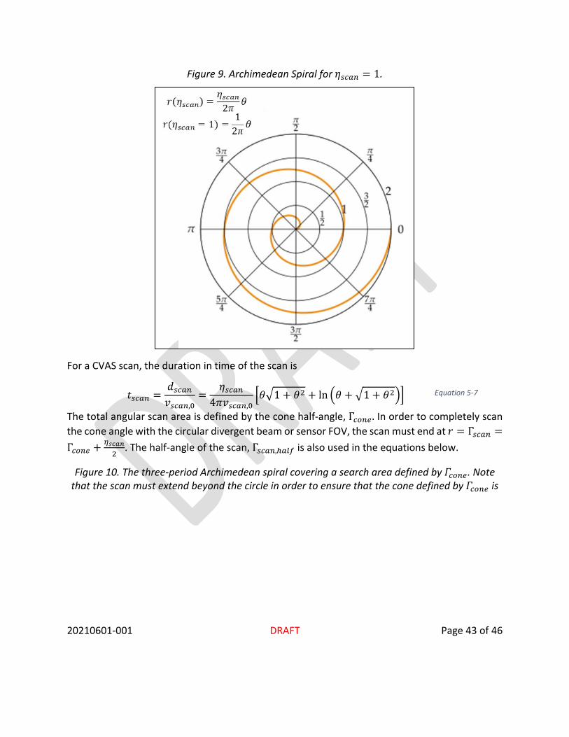
This is illustrated in Figure 9. Archimedean Spiral for ηscan = 1.
20210601-001 DRAFT Page 43 of 46
Figure 9. Archimedean Spiral for 𝜂𝜂𝑠𝑠𝑠𝑠𝑠𝑠𝐶𝐶 = 1.
For a CVAS scan, the duration in time of the scan is
𝑡𝑡𝑠𝑠𝑠𝑠𝑠𝑠𝐶𝐶 =𝑎𝑎𝑠𝑠𝑠𝑠𝑠𝑠𝐶𝐶𝑣𝑣𝑠𝑠𝑠𝑠𝑠𝑠𝐶𝐶,0
=𝜂𝜂𝑠𝑠𝑠𝑠𝑠𝑠𝐶𝐶
4𝜋𝜋𝑣𝑣𝑠𝑠𝑠𝑠𝑠𝑠𝐶𝐶,0�𝜃𝜃�1 + 𝜃𝜃2 + ln �𝜃𝜃 + �1 + 𝜃𝜃2�� Equation 5-7
The total angular scan area is defined by the cone half-angle, Γ𝑠𝑠𝑜𝑜𝐶𝐶𝑠𝑠. In order to completely scan the cone angle with the circular divergent beam or sensor FOV, the scan must end at 𝑟𝑟 = Γ𝑠𝑠𝑠𝑠𝑠𝑠𝐶𝐶 =Γ𝑠𝑠𝑜𝑜𝐶𝐶𝑠𝑠 + 𝜂𝜂𝑠𝑠𝑠𝑠𝑠𝑠𝑠𝑠
2. The half-angle of the scan, Γ𝑠𝑠𝑠𝑠𝑠𝑠𝐶𝐶,ℎ𝑠𝑠𝑜𝑜𝑎𝑎 is also used in the equations below.
Figure 10. The three-period Archimedean spiral covering a search area defined by 𝛤𝛤𝑠𝑠𝑜𝑜𝐶𝐶𝑠𝑠. Note that the scan must extend beyond the circle in order to ensure that the cone defined by 𝛤𝛤𝑠𝑠𝑜𝑜𝐶𝐶𝑠𝑠 is

20210601-001 DRAFT Page 44 of 46
fully-inscribed within the scan region. The scan cone angle is 𝛤𝛤𝑠𝑠𝑠𝑠𝑠𝑠𝐶𝐶 (please note that the half angle is annotated in the figure).
The scan of this cone is completed when 𝜃𝜃 = 𝜃𝜃2 and . This condition is met when
Γ 𝑠𝑠𝑠𝑠𝑠𝑠𝐶𝐶,ℎ𝑠𝑠𝑜𝑜𝑎𝑎 = 𝑟𝑟(𝜃𝜃2) = 𝜃𝜃2 ∗ 𝑏𝑏 = 𝜃𝜃2 ⋅𝜂𝜂𝑠𝑠𝑠𝑠𝑠𝑠𝐶𝐶
2𝜋𝜋 Equation 5-8
𝜃𝜃2 then becomes
𝜃𝜃2 =2πΓscan,half
𝜂𝜂𝑠𝑠𝑠𝑠𝑠𝑠𝐶𝐶 Equation 5-9
Which then, for the full cone angle Γ𝑠𝑠𝑠𝑠𝑠𝑠𝐶𝐶,
𝜃𝜃2 =πΓ𝑠𝑠𝑠𝑠𝑠𝑠𝐶𝐶𝜂𝜂𝑠𝑠𝑠𝑠𝑠𝑠𝐶𝐶
Equation 5-10
Inserting Equation 5-10 into Equation 5-7 gives

20210601-001 DRAFT Page 45 of 46
𝑡𝑡𝑠𝑠𝑠𝑠𝑠𝑠𝐶𝐶(Γ) =𝑎𝑎𝑠𝑠𝑠𝑠𝑠𝑠𝐶𝐶(Γ)𝑣𝑣𝑠𝑠𝑠𝑠𝑠𝑠𝐶𝐶,0
=𝜂𝜂𝑠𝑠𝑠𝑠𝑠𝑠𝐶𝐶
4𝜋𝜋𝑣𝑣𝑠𝑠𝑠𝑠𝑠𝑠𝐶𝐶,0�πΓ𝜂𝜂𝑠𝑠𝑠𝑠𝑠𝑠𝐶𝐶
�1 + �πΓ𝜂𝜂𝑠𝑠𝑠𝑠𝑠𝑠𝐶𝐶
�2
+ ln�πΓ𝜂𝜂𝑠𝑠𝑠𝑠𝑠𝑠𝐶𝐶
+ �1 + �πΓ𝜂𝜂𝑠𝑠𝑠𝑠𝑠𝑠𝐶𝐶
�2
��
Equation 5-11
The scan may now be defined by the parameters in the following table:
Table 19
Parameter Description Notes 𝚪𝚪𝒔𝒔𝒔𝒔𝒔𝒔𝒔𝒔 The cone angle of the
scan. This is defined for a circular cone.
𝒕𝒕𝒔𝒔𝒔𝒔𝒔𝒔𝒔𝒔 The scan duration in time. The scan duration is the time required to complete one spiral scan of the cone.
𝜼𝜼𝒔𝒔𝒔𝒔𝒔𝒔𝒔𝒔 The required scan step-size.
The scan step size is the distance between the spirals along the line extending from the origin in the direction of 𝜃𝜃.
5.1. Spiral Scan
In a Spiral Scan process, both OCTs execute constant-velocity Archimedean Spiral (CVAS) scans simultaneously.
5.2. Nested Spiral Scan
For a nested spiral scan, one additional parameter is required: the step size for the outer loop of the nested scans. The OCT assigned to the outer loop will step and stare along the defined Archimedean Spiral while the OCT assigned to the inner loop performs a CVAS scan. The step size, denoted 𝜂𝜂𝑠𝑠𝑠𝑠𝑠𝑠𝑠𝑠, is the distance along the spiral scan path to be taken between steps. This slew and settle must complete within the time 𝑡𝑡𝑠𝑠𝑠𝑠𝑠𝑠𝑠𝑠.
The total scan duration 𝑡𝑡𝑠𝑠𝑠𝑠𝑠𝑠𝐶𝐶 is then

20210601-001 DRAFT Page 46 of 46
𝑡𝑡𝑠𝑠𝑠𝑠𝑠𝑠𝐶𝐶 = ��𝑡𝑡𝑠𝑠𝑠𝑠𝑠𝑠𝐶𝐶(𝑖𝑖𝐶𝐶𝐶𝐶𝑠𝑠𝐶𝐶 𝑜𝑜𝑜𝑜𝑜𝑜𝑠𝑠) + 𝑡𝑡𝑠𝑠𝑠𝑠𝑠𝑠𝑠𝑠�
𝐶𝐶
Equation 5-12
Where 𝑡𝑡𝑠𝑠𝑠𝑠𝑠𝑠𝐶𝐶,𝑖𝑖𝐶𝐶𝐶𝐶𝑠𝑠𝐶𝐶 𝑜𝑜𝑜𝑜𝑜𝑜𝑠𝑠 is the total time to complete a single CVAS scan.
Recommended