SAL-U Series Self-contained Hopper Loader
Date: Sep. 2015
Version: Ver.B (English)

3(86)
Contents
1. General Description .....................................................................................9
1.1 Coding Principle ....................................................................................10
1.2 Feature..................................................................................................10
1.3 Technical Specifications........................................................................12
1.3.1 Dimensions..................................................................................12
1.3.2 Specifications ..............................................................................13
1.3.3 SAL-U Hopper Base Installation Size ..........................................13
1.3.4 Hopper Base Installation Size Table............................................14
1.3.5 Loading Capacity.........................................................................15
1.4 Safety Regulations ................................................................................16
1.4.1 Safety Signs and Labels ..............................................................16
1.5 Exemption Clause.................................................................................16
2. Structure Characteristics and Working Principle ....................................17
2.1 Working Principle ..................................................................................17
2.1.1 Working Principle Diagram of SAL-U-(CA) ..................................17
2.1.2 Working Principle of SAL-U-E(EA) ..............................................18
2.1.3 Working Principle of SAL-3U/6U-3 ..............................................19
2.2 Assembly Drawing ................................................................................20
2.2.1 Assembly Drawing (SAL-1U) .......................................................20
2.2.2 Parts List (SAL-1U)......................................................................21
2.2.3 Assembly Drawing (SAL-1U-E) ...................................................23
2.2.4 Parts List (SAL-1U-E) ..................................................................24
2.2.5 Assembly Drawing (SAL-3U) .......................................................25
2.2.6 Parts List (SAL-3U)......................................................................26
2.2.7 Assembly Drawing (SAL-3U-E) ...................................................28
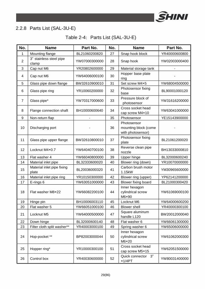
2.2.8 Parts List (SAL-3U-E) ..................................................................29
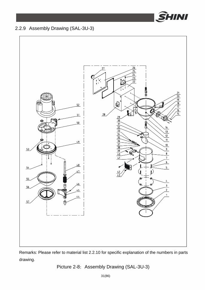
2.2.9 Assembly Drawing (SAL-3U-3)....................................................31
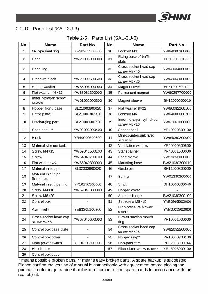
2.2.10 Parts List (SAL-3U-3) ............................................................32
2.2.11 Assembly Drawing (SAL-6U).................................................33
2.2.12 Parts List (SAL-6U) ...............................................................34
2.2.13 Assembly Drawing (SAL-6U-E) .............................................36
4(86)
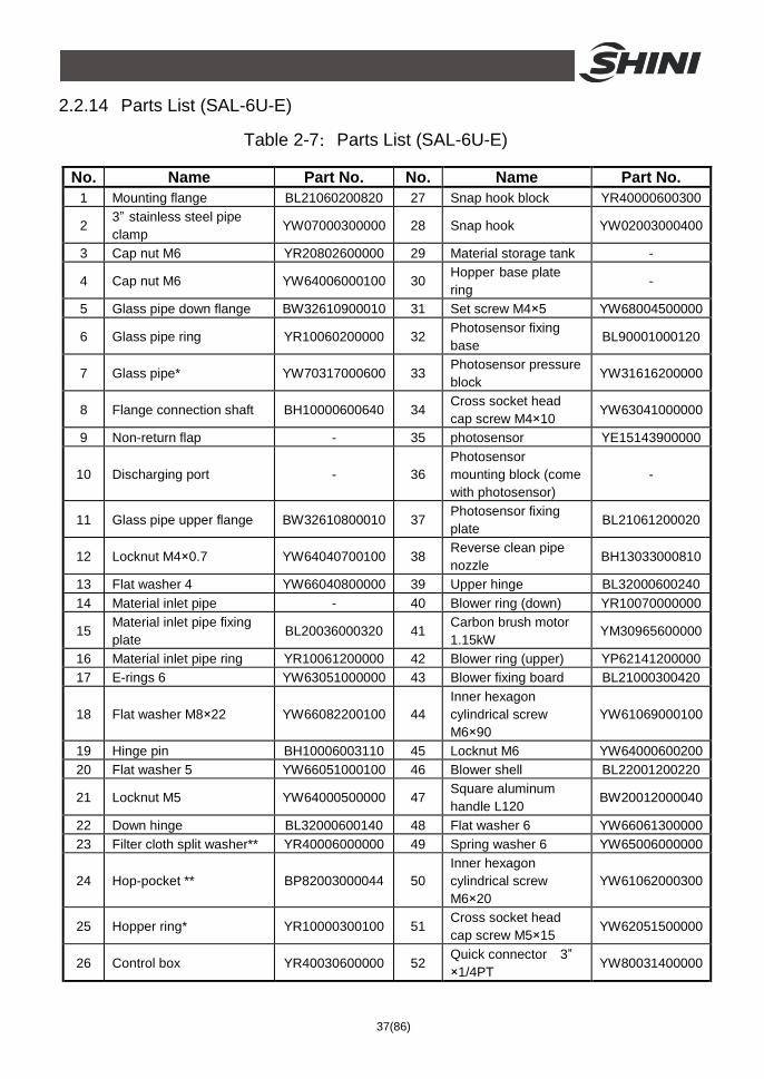
2.2.14 Parts List (SAL-6U-E)............................................................37
2.2.15 Assembly Drawing (SAL-6U-A) .............................................39
2.2.16 Parts List (SAL-6U-A)............................................................40
2.2.17 Assembly Drawing (SAL-6U-EA)...........................................42
2.2.18 Parts List (SAL-6U-EA) .........................................................43
2.2.19 Assembly Drawing (SAL-6U-3)..............................................45
2.2.20 Parts List (SAL-6U-3) ............................................................46
2.2.21 Assembly Drawing (SAL-12U)...............................................47
2.2.22 Parts List (SAL-12U) .............................................................48
2.2.23 Assembly Drawing (SAL-12U-E) ...........................................50
2.2.24 Parts List (SAL-12U-E)..........................................................51
2.2.25 Assembly Drawing (SAL-12U-A) ...........................................53
2.2.26 Parts List (SAL-12U-A)..........................................................54
2.2.27 Assembly Drawing (SAL-12U-EA).........................................56
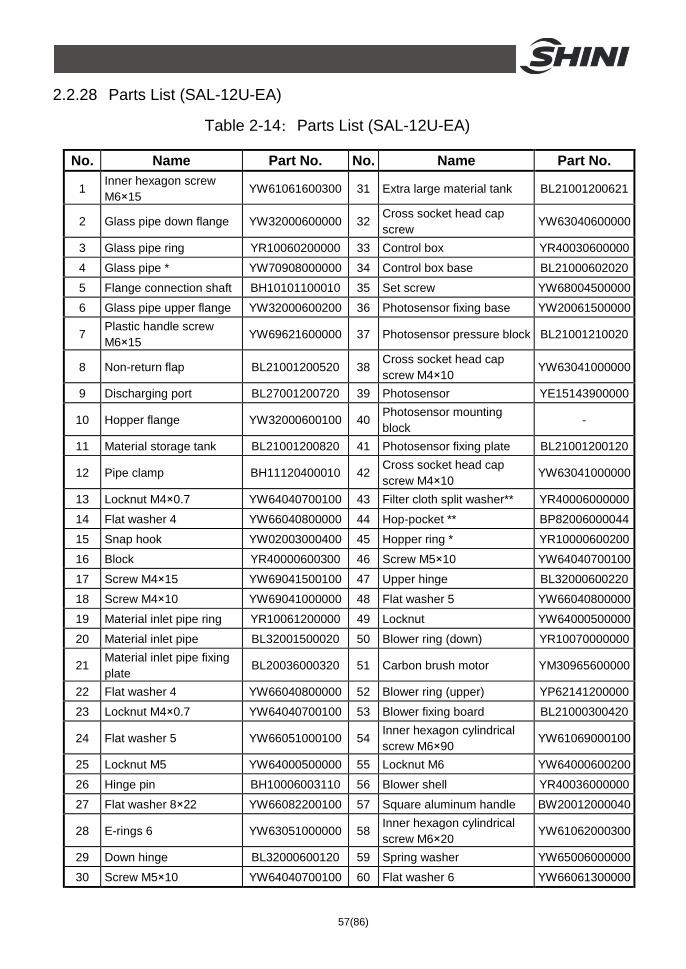
2.2.28 Parts List (SAL-12U-EA) .......................................................57
2.3 Electrical Diagram.................................................................................59
2.3.1 SAL-U Main Circuit (230V) ..........................................................59
2.3.2 SAL-U Electrical Components List (230V)...................................60
2.3.3 SAL-3U/6U-3 Main Circuit (400V)................................................61
2.3.4 SAL-3U/6U-3 Electrical Components List (400V) ........................64
2.3.5 SAL-3U/6U-3 Main Circuit (230V)................................................65
2.3.6 SAL-3U/6U-3 Electrical Components List (230V) ........................68
2.4 Description of Electrical Components ...................................................69
2.4.1 Photoelectric Switch ....................................................................69
2.4.2 Magnetic Proximity Switch...........................................................69
2.5 Optional Accessories ............................................................................70
2.5.1 Air Accumulator ...........................................................................70
2.5.1.1 Function of Air Accumulator ..............................................70
2.5.1.2 Specification of Air Accumulator........................................70
3. Installation and Debugging........................................................................71
3.1 Install the equipement on dryers or molding machines. ........................71
3.1.1 Installation of SAL-U (-A) .............................................................71
3.1.2 Power Supply of SAL-U (-A) ........................................................71
3.1.3 Installation of SAL-U-E (A)...........................................................72
5(86)
3.1.4 Power Supply of SAL-U-E(A).......................................................72
3.1.5 Installation of SAL-3U / 6U-3 .......................................................73
3.1.6 Power Supply of SAL-3U /6U-3 ...................................................73
4. Application and Operation.........................................................................74
4.1 Start / Stop the Machine........................................................................74
4.2 Keypad on the Control Panel ................................................................74
4.3 Parameters Setting ...............................................................................74
4.3.1 Enter Setting Mode of Layer One ................................................74
4.3.2 Edit Parameters...........................................................................74
4.3.3 Exit ..............................................................................................75
4.3.4 Layer One Function List ..............................................................75
4.4 Function Setting ....................................................................................76
4.4.1 Enter Setting Mode......................................................................76
4.4.2 Edit Parameters...........................................................................76
4.4.3 Exit ..............................................................................................76
4.4.4 Layer Two Function List ..............................................................76
4.5 Function Setting: Special Process.........................................................78
4.5.1 Enter special process setting Mode.............................................78
4.5.2 Edit Parameters...........................................................................78
4.5.3 Exit ..............................................................................................78
4.5.4 Special Process Function List......................................................79
4.6 Description of Operation Procedures ....................................................80
4.6.1 Operation Procedures .................................................................80
4.6.2 Alarms .........................................................................................81
5. Trouble-shooting ........................................................................................82
5.1 Trouble Shooting of single phase SAL-U. .............................................82
5.2 Trouble Shooting of 3-phase SAL-U .....................................................83
6. Maintenance and Repair ............................................................................84
6.1 Cloth Filter.............................................................................................84
6.2 Material Hopper.....................................................................................84
6.3 Glass Pipe.............................................................................................85
6.4 Magentic Proximity Switch, Photoelectric Switch ..................................85
6.5 Maintenance Schedule..........................................................................86
6(86)
6.5.1 About the Machine.......................................................................86
6.5.2 Installation & Inspection...............................................................86
6.5.3 Daily Checking.............................................................................86
6.5.4 Weekly Checking.........................................................................86
6.5.5 Monthly Checking ........................................................................86
Table Index
Table 1-1:Specifications................................................................................. 13
Table 1-2:Hopper Base Installation Size Table .............................................. 14
Table 2-1:Parts List (SAL-1U) ........................................................................ 21
Table 2-2:Parts List (SAL-1U-E)..................................................................... 24
Table 2-3:Parts List (SAL-3U) ........................................................................ 26
Table 2-4:Parts List (SAL-3U-E)..................................................................... 29
Table 2-5:Parts List (SAL-3U-3) ..................................................................... 32
Table 2-6:Parts List (SAL-6U) ........................................................................ 34
Table 2-7:Parts List (SAL-6U-E)..................................................................... 37
Table 2-8:Parts List (SAL-6U-A)..................................................................... 40
Table 2-9:Parts List (SAL-6U-EA) .................................................................. 43
Table 2-10:Parts List (SAL-6U-3) ................................................................... 46
Table 2-11:Parts List (SAL-12U) .................................................................... 48
Table 2-12:Parts List (SAL-12U-E)................................................................. 51
Table 2-13:Parts List (SAL-12U-A)................................................................. 54
Table 2-14:Parts List (SAL-12U-EA) .............................................................. 57
Table 2-15:Electrical Components List (SAL-1U) (230V) ............................... 60
Table 2-16:Electrical Components List (SAL-3U~12U) (230V) ...................... 60
Table 2-17:Electrical Components List (SAL-U~E) (230V) ............................ 60
Table 2-18:Electrical Components List (SAL-3U-3) (400V)............................ 64
Table 2-19:Electrical Components List (SAL-6U-3) (400V)............................ 64
Table 2-20:Electrical Components List (SAL-3U-3) (230V)............................ 68
Table 2-21:Electrical Components List (SAL-6U-3) (230V)............................ 68
Picture Index
7(86)
Picture 1-1:SAL-U Dimensions....................................................................... 12
Picture 1-2:SAL-U-E Dimensions................................................................... 12
Picture 1-3:SAL-U-3 Dimensions ................................................................... 12
Picture 1-4:SAL-1U Hopper Base Installation Size ........................................ 13
Picture 1-5:SAL-1 U and Models above Hopper Base Installation Size ......... 14
Picture 1-6:SAL-U-E(EA) Hopper Base Installation Size................................ 14
Picture 1-7:Loading Capacity ......................................................................... 15
Picture 2-1:Working Principle of SAL-U-(CA)................................................. 17
Picture 2-2:Working Principle of SAL-U-E(EA)............................................... 18
Picture 2-3:Working Principle of SAL-3U/6U-3............................................... 19
Picture 2-4:Assembly Drawing (SAL-1U) ....................................................... 20
Picture 2-5:Assembly Drawing (SAL-1U-E).................................................... 23
Picture 2-6:Assembly Drawing (SAL-3U) ....................................................... 25
Picture 2-7:Assembly Drawing (SAL-3U-E).................................................... 28
Picture 2-8:Assembly Drawing (SAL-3U-3) .................................................... 31
Picture 2-9:Assembly Drawing (SAL-6U) ....................................................... 33
Picture 2-10:Assembly Drawing (SAL-6U-E).................................................. 36
Picture 2-11:Assembly Drawing (SAL-6U-A).................................................. 39
Picture 2-12:Assembly Drawing (SAL-6U-EA) ............................................... 42
Picture 2-13:Assembly Drawing (SAL-6U-3) .................................................. 45
Picture 2-14:Assembly Drawing (SAL-12U) ................................................... 47
Picture 2-15:Assembly Drawing (SAL-12U-E)................................................ 50
Picture 2-16:Assembly Drawing (SAL-12U-A)................................................ 53
Picture 2-17:Assembly Drawing (SAL-12U-EA) ............................................. 56
Picture 2-18:SAL-U Main Circuit (230V)......................................................... 59
Picture 2-19:SAL-3/6U-3 Main Circuit 1 (400V) ............................................. 61
Picture 2-20:SAL-3/6U-3 Main Circuit 2 (400V) ............................................. 62
Picture 2-21:SAL-3/6U-3 Main Circuit 3 (400V) ............................................. 63
Picture 2-22:SAL-3/6U-3 Main Circuit 1 (230V) ............................................. 65
Picture 2-23:SAL-3/6U-3 Main Circuit 2 (230V) ............................................. 66
Picture 2-24:SAL-3/6U-3 Main Circuit 3 (230V) ............................................. 67
Picture 2-25:Photoelectric Switch................................................................... 69
Picture 2-26:Magnetic Proximity Switch ......................................................... 69
Picture 2-27:Air Accumulator ......................................................................... 70
8(86)
Picture 3-1:Installation of SAL-U (-A) ............................................................. 71
Picture 3-2:Installation of SAL-U-E (A)........................................................... 72
Picture 3-3:Installation of SAL-3U / 6U-3 ....................................................... 73
9(86)
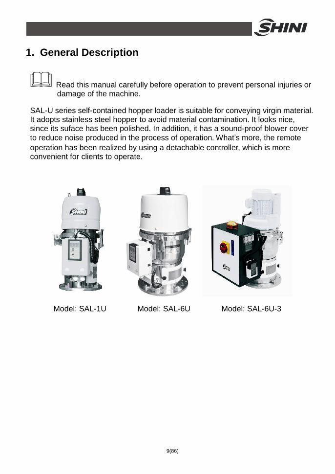
1. General Description
Read this manual carefully before operation to prevent personal injuries or damage of the machine.
SAL-U series self-contained hopper loader is suitable for conveying virgin material. It adopts stainless steel hopper to avoid material contamination. It looks nice, since its suface has been polished. In addition, it has a sound-proof blower cover to reduce noise produced in the process of operation. What’s more, the remote operation has been realized by using a detachable controller, which is more convenient for clients to operate.
Model: SAL-1U Model: SAL-6U Model: SAL-6U-3
10(86)
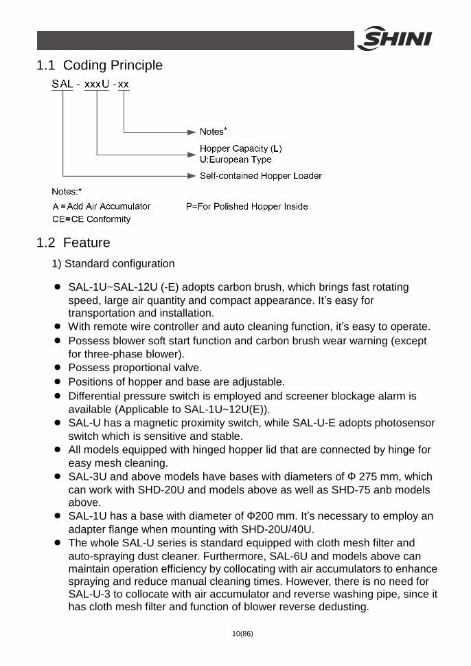
1.1 Coding Principle
1.2 Feature 1) Standard configuration
● SAL-1U~SAL-12U (-E) adopts carbon brush, which brings fast rotating speed, large air quantity and compact appearance. It’s easy for transportation and installation.
● With remote wire controller and auto cleaning function, it’s easy to operate. ● Possess blower soft start function and carbon brush wear warning (except
for three-phase blower). ● Possess proportional valve. ● Positions of hopper and base are adjustable. ● Differential pressure switch is employed and screener blockage alarm is
available (Applicable to SAL-1U~12U(E)). ● SAL-U has a magnetic proximity switch, while SAL-U-E adopts photosensor
switch which is sensitive and stable. ● All models equipped with hinged hopper lid that are connected by hinge for
easy mesh cleaning. ● SAL-3U and above models have bases with diameters of Ф 275 mm, which
can work with SHD-20U and models above as well as SHD-75 anb models above.
● SAL-1U has a base with diameter of Ф200 mm. It’s necessary to employ an adapter flange when mounting with SHD-20U/40U.
● The whole SAL-U series is standard equipped with cloth mesh filter and auto-spraying dust cleaner. Furthermore, SAL-6U and models above can maintain operation efficiency by collocating with air accumulators to enhance spraying and reduce manual cleaning times. However, there is no need for SAL-U-3 to collocate with air accumulator and reverse washing pipe, since it has cloth mesh filter and function of blower reverse dedusting.
11(86)
2) Accessory option
● provide multi-functional installation frame HMB-900 with 900 mm maximum adjustable diameter.
● Standard Collective Hopper SCH-6U/12U/24U and Euro Insulation Collective Hopper SICH-6U/12U/24U are optional; add this collective hopper at bottom of the magnetic-proximity switch hopper can be directly mounted on the injection molding machine.
● It is available to select air accumulator to enhance auto spraying function (applicable to SAL-6U /12U).
● Buzzer is optional (applicable to SAL-U-3 series). ● Option for propotion mixing SPV-U.
All maintenance work should be carried out by a person with technical training or corresponding professional experience. The manual contains instructions for both operating and maintenance. Chapter 6 contains maintenance instructions for service engineers. Other chapters contain instructions for the daily operator.
Any modifications of the machine must be approved by SHINI in order to avoid personal injury and damage to machine. We shall not be liable for any damage caused by unauthorized change of the machine.
Our company provides after-sales service. Should you have any problem during using the machine, please contact the company or the local vendor.
Headquarter and Taipei factory: Tel: + 886 (0)2 2680 9119 Shini Plastics Technologies (Dongguan), Inc: Tel: + 86 (0)769 8111 6600 Email: [email protected] Shini Plastics Technologies India Pvt.Ltd.: Tel: + 91 250 3021 166. Please refer to shini.com/en/worldwide.html for local vendor near you.
12(86)
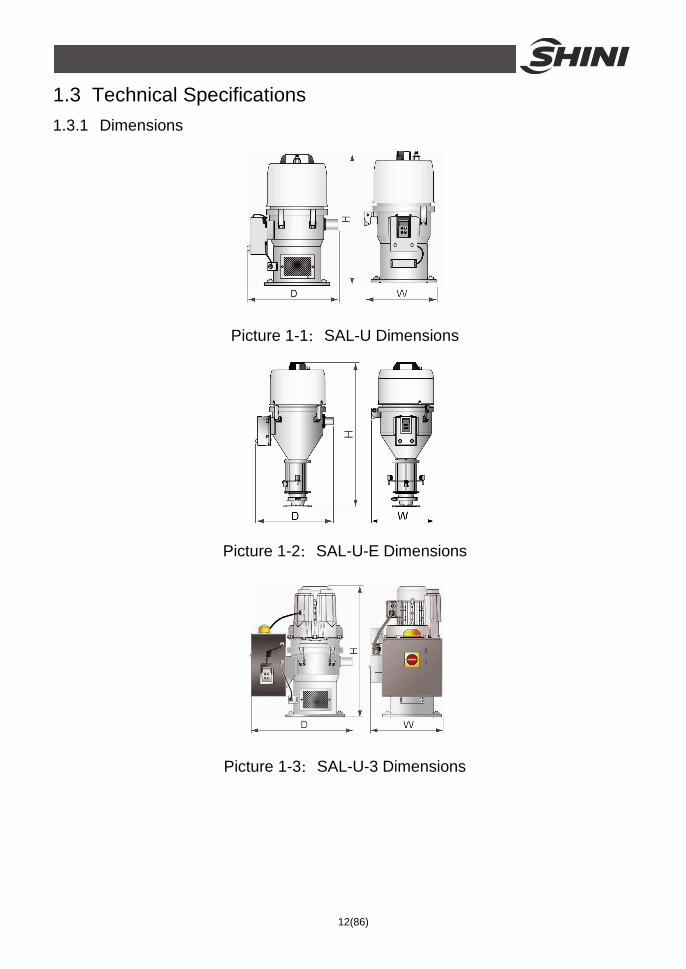
1.3 Technical Specifications 1.3.1 Dimensions
Picture 1-1:SAL-U Dimensions
Picture 1-2:SAL-U-E Dimensions
Picture 1-3:SAL-U-3 Dimensions
13(86)
1.3.2 Specifications
Table 1-1:Specifications
Model SAL-1U SAL-3U SAL-6U SAL-12U SAL-1U-E SAL-3U-E SAL-6U-E SAL-12U-E SAL-3U-3 SAL-6U-3
Blower Type Carbon brush Inductive
Blower Power (kW) (50/60Hz)
0.46 / 0.55
1.15 / 1.32 0.46 / 0.55 1.15 / 1.32 0.37 / 0.42 0.75 / 0.85
Conveying Pipe Internal Dia. (inch)
1.5 1.5 1.5 1.5 1.5 1.5 1.5 1.5 1.5 1.5
Conveying Capacity (kg/hr)
30 200 300 400 30 200 300 400 200 300
Hopper Volume (L)
1 3 6 12 1.5 3 6 12 3 6
Power Supply (v) 1Ф, 115 / 230VAC, 50 / 60Hz 3Ф, 230 / 400 / 460 / 575VAC, 50 / 60Hz
Auto-Cleaning Function
Standard
Air Accumulator None Optional None Optional None
Dimensions
H (mm) 525 555 645 745 630 740 800 935 605 675
W (mm) 270 305 340 340 260 305 340 340 335 370
D (mm) 325 305 410 410 325 370 410 410 475 540
Weight (kg) 10 11 12 14 10 13 16 18 18 33
Note: 1) For hopper inside polished ones, add "P" at model behind. We reserve the right to change 2) Conveying capacity:Plastic material of bulk specifications without prior notice.
density 0.65kg/L, dia. 3~5 mm, vertical conveying height: 4m, horizontal conveying distance: 1m.
3) Compressed air supply: 4~6kgf/cm2.
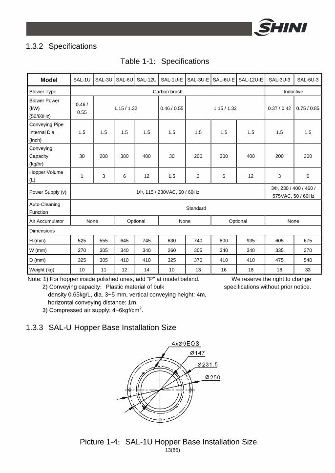
1.3.3 SAL-U Hopper Base Installation Size
Picture 1-4:SAL-1U Hopper Base Installation Size
14(86)
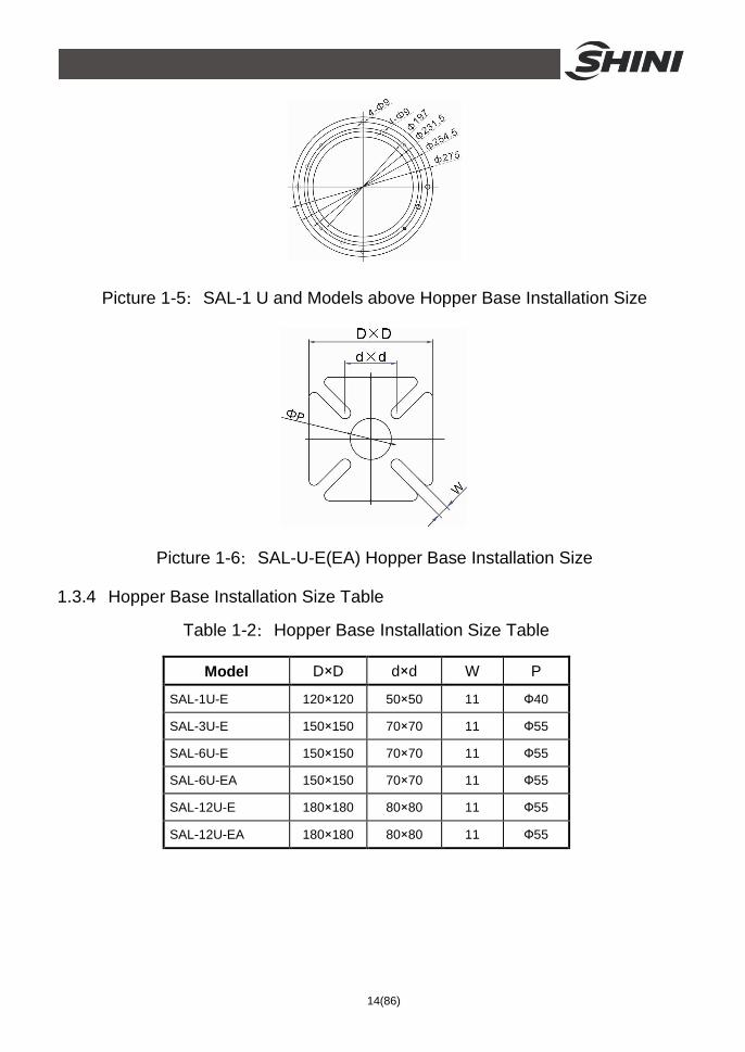
Picture 1-5:SAL-1 U and Models above Hopper Base Installation Size
Picture 1-6:SAL-U-E(EA) Hopper Base Installation Size
1.3.4 Hopper Base Installation Size Table
Table 1-2:Hopper Base Installation Size Table
Model D×D d×d W P
SAL-1U-E 120×120 50×50 11 Ф40
SAL-3U-E 150×150 70×70 11 Ф55
SAL-6U-E 150×150 70×70 11 Ф55
SAL-6U-EA 150×150 70×70 11 Ф55
SAL-12U-E 180×180 80×80 11 Ф55
SAL-12U-EA 180×180 80×80 11 Ф55
15(86)
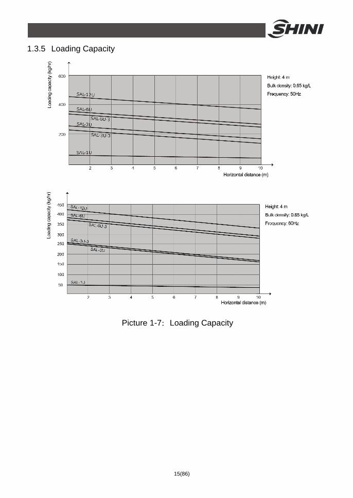
1.3.5 Loading Capacity
Picture 1-7:Loading Capacity
16(86)
1.4 Safety Regulations Strictly abide by the following safety regulations to prevent personal injuries and damage of equipment.
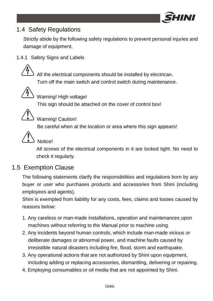
1.4.1 Safety Signs and Labels
All the electrical components should be installed by electrican. Turn off the main switch and control switch during maintenance.
Warning! High voltage! This sign should be attached on the cover of control box!
Warning! Caution! Be careful when at the location or area where this sign appears!
Notice! All screws of the electrical components in it are locked tight. No need to
check it regularly.
1.5 Exemption Clause The following statements clarify the responsibilities and regulations born by any buyer or user who purchases products and accessories from Shini (including employees and agents). Shini is exempted from liability for any costs, fees, claims and losses caused by reasons below:
1. Any careless or man-made installations, operation and maintenances upon machines without referring to the Manual prior to machine using.
2. Any incidents beyond human controls, which include man-made vicious or deliberate damages or abnormal power, and machine faults caused by irresistible natural disasters including fire, flood, storm and earthquake.
3. Any operational actions that are not authorized by Shini upon equipment, including adding or replacing accessories, dismantling, delivering or repairing.
4. Employing consumables or oil media that are not appointed by Shini.
17(86)
2. Structure Characteristics and Working Principle 2.1 Working Principle
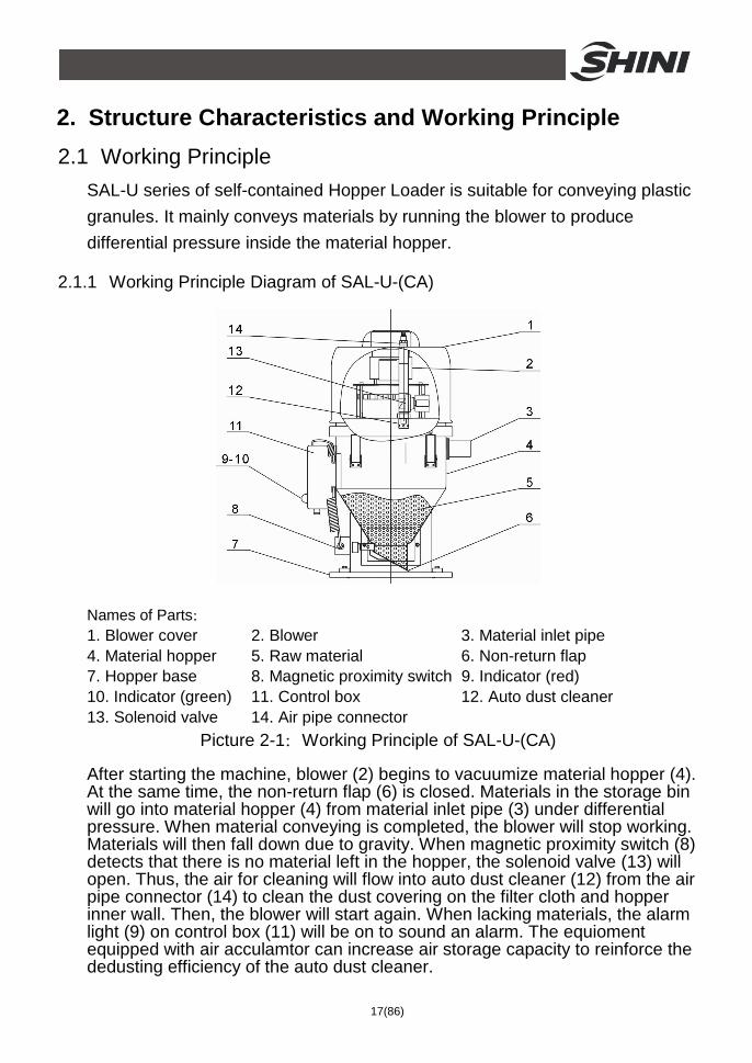
SAL-U series of self-contained Hopper Loader is suitable for conveying plastic granules. It mainly conveys materials by running the blower to produce differential pressure inside the material hopper.
2.1.1 Working Principle Diagram of SAL-U-(CA)
Names of Parts: 1. Blower cover 2. Blower 3. Material inlet pipe 4. Material hopper 5. Raw material 6. Non-return flap 7. Hopper base 8. Magnetic proximity switch 9. Indicator (red) 10. Indicator (green) 11. Control box 12. Auto dust cleaner 13. Solenoid valve 14. Air pipe connector
Picture 2-1:Working Principle of SAL-U-(CA)
After starting the machine, blower (2) begins to vacuumize material hopper (4). At the same time, the non-return flap (6) is closed. Materials in the storage bin will go into material hopper (4) from material inlet pipe (3) under differential pressure. When material conveying is completed, the blower will stop working. Materials will then fall down due to gravity. When magnetic proximity switch (8) detects that there is no material left in the hopper, the solenoid valve (13) will open. Thus, the air for cleaning will flow into auto dust cleaner (12) from the air pipe connector (14) to clean the dust covering on the filter cloth and hopper inner wall. Then, the blower will start again. When lacking materials, the alarm light (9) on control box (11) will be on to sound an alarm. The equioment equipped with air acculamtor can increase air storage capacity to reinforce the dedusting efficiency of the auto dust cleaner.
18(86)
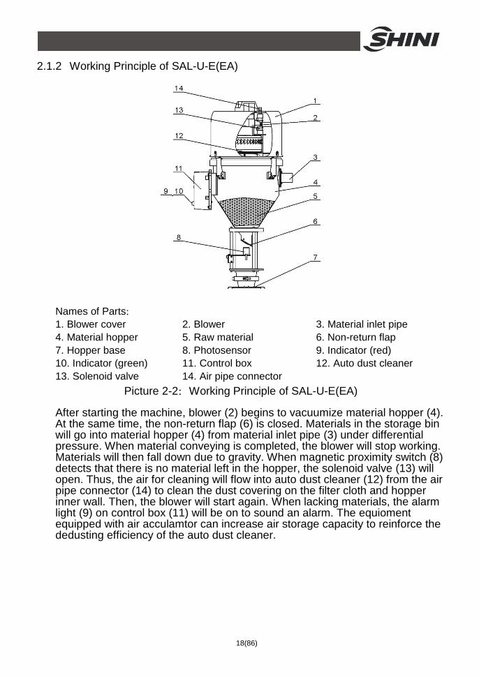
2.1.2 Working Principle of SAL-U-E(EA)
Names of Parts: 1. Blower cover 2. Blower 3. Material inlet pipe 4. Material hopper 5. Raw material 6. Non-return flap 7. Hopper base 8. Photosensor 9. Indicator (red) 10. Indicator (green) 11. Control box 12. Auto dust cleaner 13. Solenoid valve 14. Air pipe connector
Picture 2-2:Working Principle of SAL-U-E(EA)
After starting the machine, blower (2) begins to vacuumize material hopper (4). At the same time, the non-return flap (6) is closed. Materials in the storage bin will go into material hopper (4) from material inlet pipe (3) under differential pressure. When material conveying is completed, the blower will stop working. Materials will then fall down due to gravity. When magnetic proximity switch (8) detects that there is no material left in the hopper, the solenoid valve (13) will open. Thus, the air for cleaning will flow into auto dust cleaner (12) from the air pipe connector (14) to clean the dust covering on the filter cloth and hopper inner wall. Then, the blower will start again. When lacking materials, the alarm light (9) on control box (11) will be on to sound an alarm. The equioment equipped with air acculamtor can increase air storage capacity to reinforce the dedusting efficiency of the auto dust cleaner.
19(86)
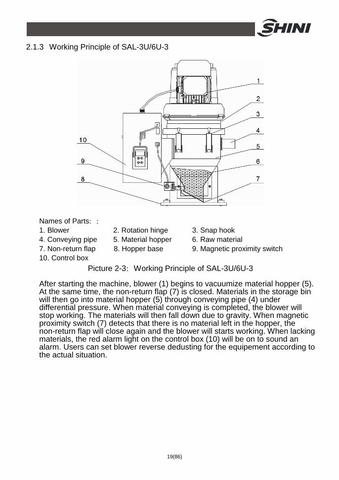
2.1.3 Working Principle of SAL-3U/6U-3
Names of Parts:: 1. Blower 2. Rotation hinge 3. Snap hook 4. Conveying pipe 5. Material hopper 6. Raw material 7. Non-return flap 8. Hopper base 9. Magnetic proximity switch 10. Control box
Picture 2-3:Working Principle of SAL-3U/6U-3
After starting the machine, blower (1) begins to vacuumize material hopper (5). At the same time, the non-return flap (7) is closed. Materials in the storage bin will then go into material hopper (5) through conveying pipe (4) under differential pressure. When material conveying is completed, the blower will stop working. The materials will then fall down due to gravity. When magnetic proximity switch (7) detects that there is no material left in the hopper, the non-return flap will close again and the blower will starts working. When lacking materials, the red alarm light on the control box (10) will be on to sound an alarm. Users can set blower reverse dedusting for the equipement according to the actual situation.
20(86)
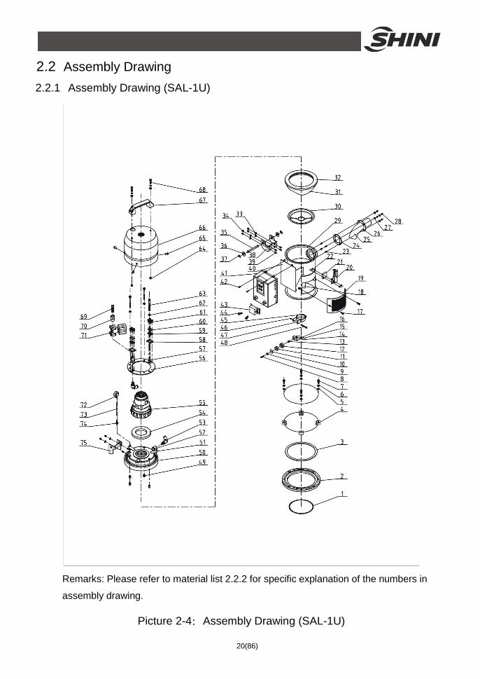
2.2 Assembly Drawing 2.2.1 Assembly Drawing (SAL-1U)
Remarks: Please refer to material list 2.2.2 for specific explanation of the numbers in
assembly drawing.
Picture 2-4:Assembly Drawing (SAL-1U)
21(86)
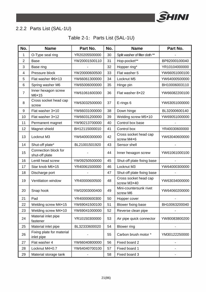
2.2.2 Parts List (SAL-1U)
Table 2-1:Parts List (SAL-1U)
No. Name Part No. No. Name Part No. 1 O-Type seal ring YR20205500000 30 Split washer of filter cloth ** - 2 Base YW20001500110 31 Hop-pocket** BP82000100040
3 Base ring - 32 Hopper ring* YR10104000000
4 Pressure block YW20000600500 33 Flat washer 5 YW66051000100
5 Flat washer Ф6×13 YW66061300000 34 Locknut M5 YW64000500000
6 Spring washer M6 YW65006000000 35 Hinge pin BH10006003110
7 Inner hexagon screw M6×15
YW61061600300 36 Flat washer 8×22 YW66082200100
8 Cross socket head cap screw
YW63032500000 37 E-rings 6 YW63051000000
9 Flat washer 3×10 YW66031000000 38 Down hinge BL32000600140
10 Flat washer 3×12 YW66031200000 39 Welding screw M5×10 YW69051000000
11 Permanent magnet YW90213700000 40 Control box base -
12 Magnet shield BH12115000010 41 Control box YR40030600000
13 Locknut M3 YW64000300000 42 Cross socket head cap screw M4×6
YW63040600000
14 Shut-off plate* BL21001501920 43 Sensor shell -
15 Connection block for shut-off plate
- 44 Inner hexagon screw YW61061000100
16 Lentil head screw YW09250500000 45 Shut-off plate fixing base -
17 Star knob M6×15 YR40061500000 46 Locknut M3 YW64000300000
18 Discharge port - 47 Shut-off plate fixing base -
19 Ventilation window YR40000600500 48 Cross socket head cap screw M3×40
YW63034000000
20 Snap hook YW02003000400 49 Mini-countersunk rivet screw M6
YW64060200000
21 Pad YR40000600300 50 Hopper cover -
22 Welding screw M4×15 YW69041500100 51 Blower fixing base BH10063200040
23 Welding screw M4×10 YW69041000000 52 Reverse clean pipe -
24 Material inlet pipe fastener
YR10150300000 53 Air pipe quick connector YW80083800200
25 Material inlet pipe BL32333600020 54 Blower ring -
26 Fixing plate for material inlet pipe
- 55 Carbon brush motor * YM30122250000
27 Flat washer 4 YW66040800000 56 Fixed board 2 -
28 Locknut M4×0.7 YW64040700100 57 Fixed board 1 -
29 Material storage tank - 58 Fixed board 3 -
22(86)
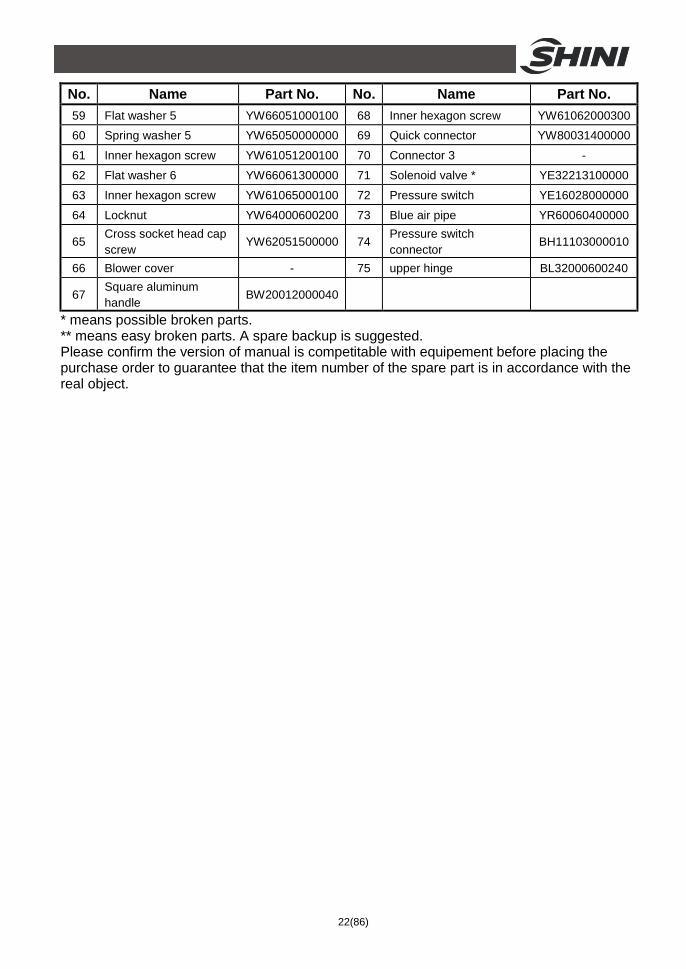
No. Name Part No. No. Name Part No. 59 Flat washer 5 YW66051000100 68 Inner hexagon screw YW61062000300 60 Spring washer 5 YW65050000000 69 Quick connector YW80031400000
61 Inner hexagon screw YW61051200100 70 Connector 3 -
62 Flat washer 6 YW66061300000 71 Solenoid valve * YE32213100000
63 Inner hexagon screw YW61065000100 72 Pressure switch YE16028000000
64 Locknut YW64000600200 73 Blue air pipe YR60060400000
65 Cross socket head cap screw
YW62051500000 74 Pressure switch connector
BH11103000010
66 Blower cover - 75 upper hinge BL32000600240
67 Square aluminum handle
BW20012000040
* means possible broken parts. ** means easy broken parts. A spare backup is suggested. Please confirm the version of manual is competitable with equipement before placing the purchase order to guarantee that the item number of the spare part is in accordance with the real object.
23(86)
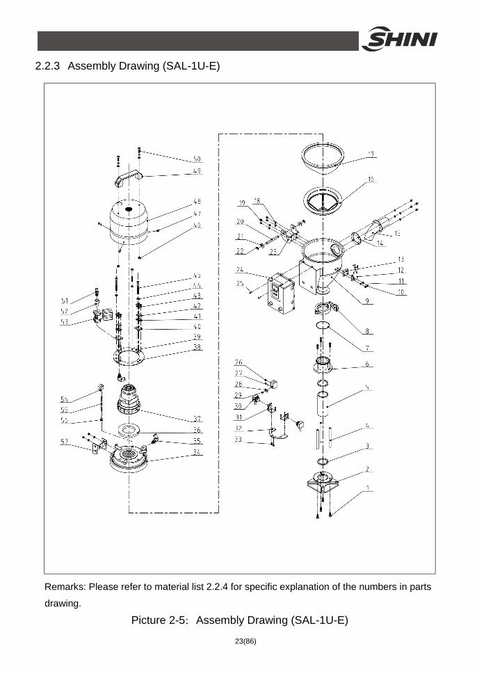
2.2.3 Assembly Drawing (SAL-1U-E)
Remarks: Please refer to material list 2.2.4 for specific explanation of the numbers in parts
drawing.
Picture 2-5:Assembly Drawing (SAL-1U-E)
24(86)
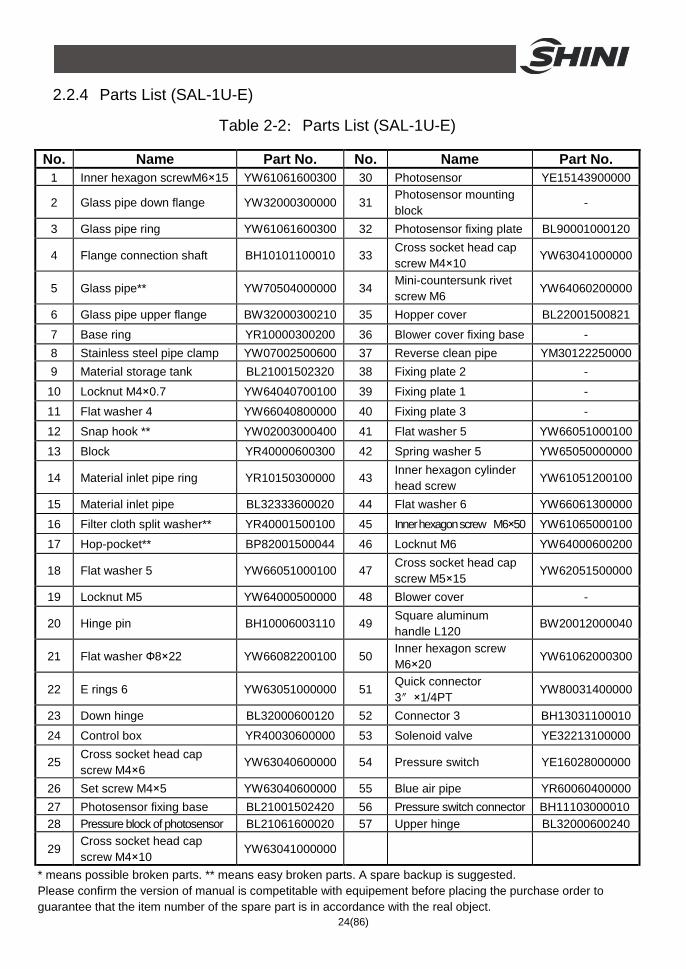
2.2.4 Parts List (SAL-1U-E)
Table 2-2:Parts List (SAL-1U-E)
No. Name Part No. No. Name Part No. 1 Inner hexagon screwM6×15 YW61061600300 30 Photosensor YE15143900000
2 Glass pipe down flange YW32000300000 31 Photosensor mounting block
-
3 Glass pipe ring YW61061600300 32 Photosensor fixing plate BL90001000120
4 Flange connection shaft BH10101100010 33 Cross socket head cap screw M4×10
YW63041000000
5 Glass pipe** YW70504000000 34 Mini-countersunk rivet screw M6
YW64060200000
6 Glass pipe upper flange BW32000300210 35 Hopper cover BL22001500821
7 Base ring YR10000300200 36 Blower cover fixing base - 8 Stainless steel pipe clamp YW07002500600 37 Reverse clean pipe YM30122250000 9 Material storage tank BL21001502320 38 Fixing plate 2 -
10 Locknut M4×0.7 YW64040700100 39 Fixing plate 1 -
11 Flat washer 4 YW66040800000 40 Fixing plate 3 -
12 Snap hook ** YW02003000400 41 Flat washer 5 YW66051000100
13 Block YR40000600300 42 Spring washer 5 YW65050000000
14 Material inlet pipe ring YR10150300000 43 Inner hexagon cylinder head screw
YW61051200100
15 Material inlet pipe BL32333600020 44 Flat washer 6 YW66061300000
16 Filter cloth split washer** YR40001500100 45 Inner hexagon screw M6×50 YW61065000100
17 Hop-pocket** BP82001500044 46 Locknut M6 YW64000600200
18 Flat washer 5 YW66051000100 47 Cross socket head cap screw M5×15
YW62051500000
19 Locknut M5 YW64000500000 48 Blower cover -
20 Hinge pin BH10006003110 49 Square aluminum handle L120
BW20012000040
21 Flat washer Ф8×22 YW66082200100 50 Inner hexagon screw M6×20
YW61062000300
22 E rings 6 YW63051000000 51 Quick connector 3″×1/4PT YW80031400000
23 Down hinge BL32000600120 52 Connector 3 BH13031100010
24 Control box YR40030600000 53 Solenoid valve YE32213100000
25 Cross socket head cap screw M4×6
YW63040600000 54 Pressure switch YE16028000000
26 Set screw M4×5 YW63040600000 55 Blue air pipe YR60060400000 27 Photosensor fixing base BL21001502420 56 Pressure switch connector BH11103000010 28 Pressure block of photosensor BL21061600020 57 Upper hinge BL32000600240
29 Cross socket head cap screw M4×10
YW63041000000
* means possible broken parts. ** means easy broken parts. A spare backup is suggested. Please confirm the version of manual is competitable with equipement before placing the purchase order to guarantee that the item number of the spare part is in accordance with the real object.
25(86)
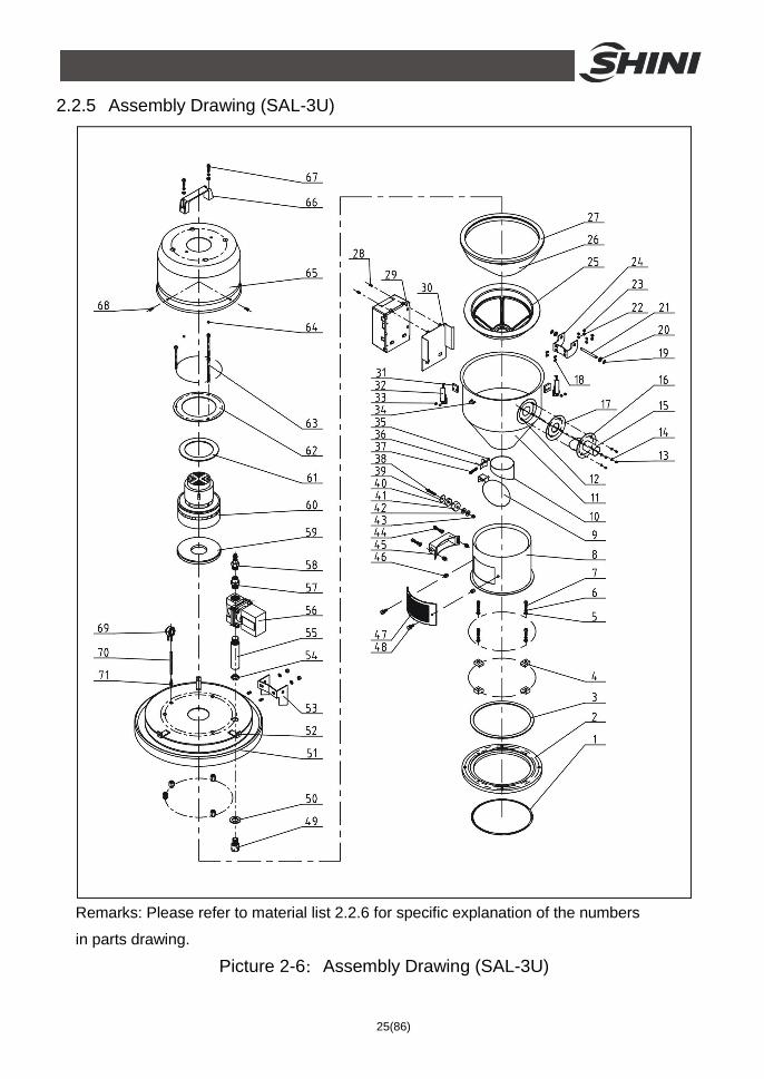
2.2.5 Assembly Drawing (SAL-3U)
Remarks: Please refer to material list 2.2.6 for specific explanation of the numbers
in parts drawing.
Picture 2-6:Assembly Drawing (SAL-3U)
26(86)
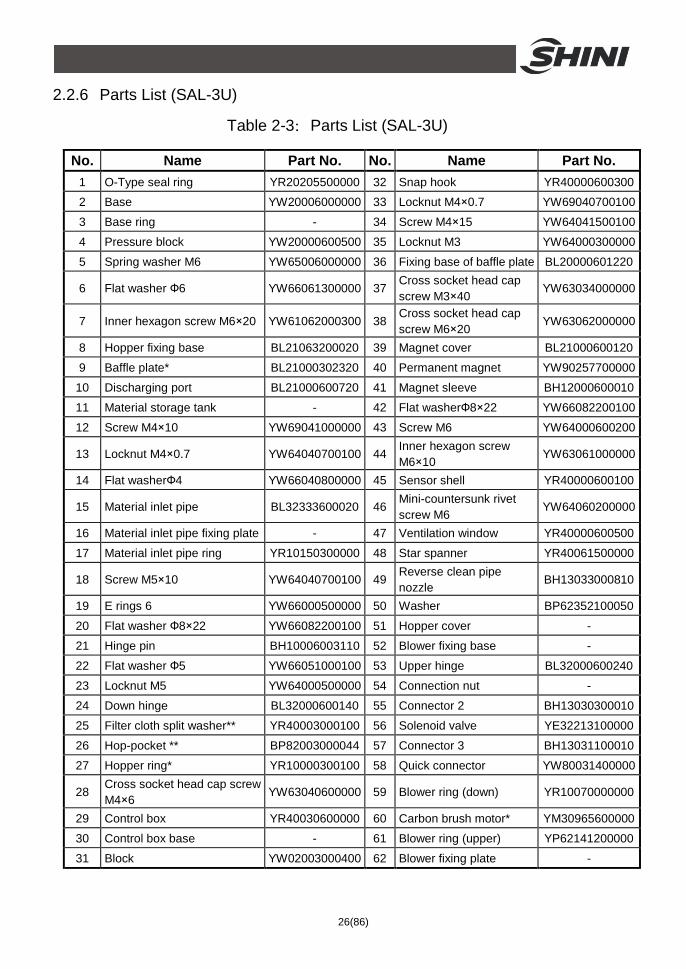
2.2.6 Parts List (SAL-3U)
Table 2-3:Parts List (SAL-3U)
No. Name Part No. No. Name Part No. 1 O-Type seal ring YR20205500000 32 Snap hook YR40000600300 2 Base YW20006000000 33 Locknut M4×0.7 YW69040700100
3 Base ring - 34 Screw M4×15 YW64041500100
4 Pressure block YW20000600500 35 Locknut M3 YW64000300000
5 Spring washer M6 YW65006000000 36 Fixing base of baffle plate BL20000601220
6 Flat washer Ф6 YW66061300000 37 Cross socket head cap screw M3×40
YW63034000000
7 Inner hexagon screw M6×20 YW61062000300 38 Cross socket head cap screw M6×20
YW63062000000
8 Hopper fixing base BL21063200020 39 Magnet cover BL21000600120
9 Baffle plate* BL21000302320 40 Permanent magnet YW90257700000
10 Discharging port BL21000600720 41 Magnet sleeve BH12000600010
11 Material storage tank - 42 Flat washerФ8×22 YW66082200100
12 Screw M4×10 YW69041000000 43 Screw M6 YW64000600200
13 Locknut M4×0.7 YW64040700100 44 Inner hexagon screw M6×10
YW63061000000
14 Flat washerФ4 YW66040800000 45 Sensor shell YR40000600100
15 Material inlet pipe BL32333600020 46 Mini-countersunk rivet screw M6
YW64060200000
16 Material inlet pipe fixing plate - 47 Ventilation window YR40000600500
17 Material inlet pipe ring YR10150300000 48 Star spanner YR40061500000
18 Screw M5×10 YW64040700100 49 Reverse clean pipe nozzle
BH13033000810
19 E rings 6 YW66000500000 50 Washer BP62352100050
20 Flat washer Ф8×22 YW66082200100 51 Hopper cover -
21 Hinge pin BH10006003110 52 Blower fixing base -
22 Flat washer Ф5 YW66051000100 53 Upper hinge BL32000600240
23 Locknut M5 YW64000500000 54 Connection nut -
24 Down hinge BL32000600140 55 Connector 2 BH13030300010
25 Filter cloth split washer** YR40003000100 56 Solenoid valve YE32213100000
26 Hop-pocket ** BP82003000044 57 Connector 3 BH13031100010
27 Hopper ring* YR10000300100 58 Quick connector YW80031400000
28 Cross socket head cap screw M4×6
YW63040600000 59 Blower ring (down) YR10070000000
29 Control box YR40030600000 60 Carbon brush motor* YM30965600000
30 Control box base - 61 Blower ring (upper) YP62141200000
31 Block YW02003000400 62 Blower fixing plate -
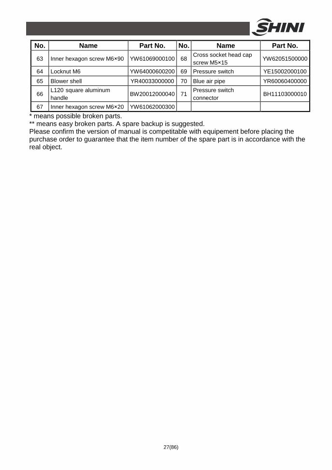
27(86)
No. Name Part No. No. Name Part No.
63 Inner hexagon screw M6×90 YW61069000100 68 Cross socket head cap screw M5×15
YW62051500000
64 Locknut M6 YW64000600200 69 Pressure switch YE15002000100
65 Blower shell YR40033000000 70 Blue air pipe YR60060400000
66 L120 square aluminum handle
BW20012000040 71 Pressure switch connector
BH11103000010
67 Inner hexagon screw M6×20 YW61062000300 * means possible broken parts. ** means easy broken parts. A spare backup is suggested. Please confirm the version of manual is competitable with equipement before placing the purchase order to guarantee that the item number of the spare part is in accordance with the real object.
28(86)
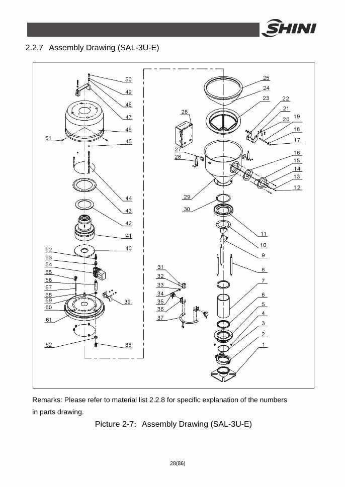
2.2.7 Assembly Drawing (SAL-3U-E)
Remarks: Please refer to material list 2.2.8 for specific explanation of the numbers
in parts drawing.
Picture 2-7:Assembly Drawing (SAL-3U-E)
29(86)
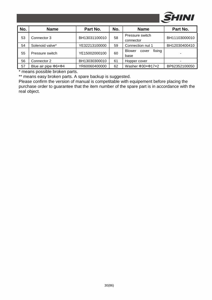
2.2.8 Parts List (SAL-3U-E)
Table 2-4:Parts List (SAL-3U-E)
No. Name Part No. No. Name Part No. 1 Mounting flange BL21060200820 27 Snap hook block YR40000600800
2 3” stainless steel pipe clamp
YW07000300000 28 Snap hook YW02003000400
3 Cap nut M6 YR20802600000 29 Material storage tank -
4 Cap nut M6 YW64006000100 30 Hopper base plate ring
-
5 Glass pipe down flange BW32610900010 31 Set screw M4×5 YW68004500000
6 Glass pipe ring YR10060200000 32 Photosensor fixing base
BL90001000120
7 Glass pipe* YW70317000600 33 Pressure block of photosensor
YW31616200000
8 Flange connection shaft BH10000600640 34 Cross socket head cap screw M4×10
YW63041000000
9 Non-return flap - 35 Photosensor YE15143900000
10 Discharging port - 36 Photosensor mounting block (come with photosensor)
-
11 Glass pipe upper flange BW32610800010 37 Photosensor fixing plate
BL21061200020
12 Locknut M4×0.7 YW64040700100 38 Reverse clean pipe nozzle
BH13033000810
13 Flat washer 4 YW66040800000 39 Upper hinge BL32000600240 14 Material inlet pipe BL32333600020 40 Blower ring (down) YR10070000000
15 Material inlet pipe fixing plate
BL20036000320 41 Carbon brush motor 1.15kW
YM30965600000
16 Material inlet pipe ring YR10150300000 42 Blower ring (upper) YP62141200000 17 E-rings 6 YW63051000000 43 Blower fixing board BL21000300420
18 Flat washer M8×22 YW66082200100 44 Inner hexagon cylindrical screw M6×90
YW61069000100
19 Hinge pin BH10006003110 45 Locknut M6 YW64000600200 20 Flat washer 5 YW66051000100 46 Blower shell YR40000300100
21 Locknut M5 YW64000500000 47 Square aluminum handle L120
BW20012000040
22 Down hinge BL32000600140 48 Flat washer 6 YW66061300000 23 Filter cloth split washer** YR40003000100 49 Spring washer 6 YW65006000000
24 Hop-pocket ** BP82003000044 50 Inner hexagon cylindrical screw M6×20
YW61062000300
25 Hopper ring* YR10000300100 51 Cross socket head cap screw M5×15
YW62051500000
26 Control box YR40030600000 52 Quick connector 3” ×1/4PT
YW80031400000
30(86)
No. Name Part No. No. Name Part No.
53 Connector 3 BH13031100010 58 Pressure switch connector
BH11103000010
54 Solenoid valve* YE32213100000 59 Connection nut 1 BH12030400410
55 Pressure switch YE15002000100 60 Blower cover fixing base
-
56 Connector 2 BH13030300010 61 Hopper cover - 57 Blue air pipe Ф6×Ф4 YR60060400000 62 Washer Ф30×Ф17×2 BP62352100050
* means possible broken parts. ** means easy broken parts. A spare backup is suggested. Please confirm the version of manual is competitable with equipement before placing the purchase order to guarantee that the item number of the spare part is in accordance with the real object.
31(86)
2.2.9 Assembly Drawing (SAL-3U-3)
Remarks: Please refer to material list 2.2.10 for specific explanation of the numbers in parts
drawing.
Picture 2-8:Assembly Drawing (SAL-3U-3)
32(86)
2.2.10 Parts List (SAL-3U-3)
Table 2-5:Parts List (SAL-3U-3) No. Name Part No. No. Name Part No.
1 O-Type seal ring YR20205500000 30 Locknut M3 YW64000300000
2 Base YW20006000000 31 Fixing base of baffle plate
BL20000601220
3 Base ring - 32 Cross socket head cap screw M3×40
YW63034000000
4 Pressure block YW20000600500 33 Cross socket head cap screw M6×20
YW63062000000
5 Spring washer YW65006000000 34 Magnet cover BL21000600120 6 Flat washer Ф6×13 YW66061300000 35 Permanent magnet YW60257700000
7 Inner hexagon screw M6×20
YW61062000300 36 Magnet sleeve BH12000600010
8 Hopper fixing base BL21000600020 37 Flat washer 8×22 YW66082200100 9 Baffle plate* BL21000302320 38 Locknut M6 YW64000600200
10 Discharging port BL21000600720 39 Inner hexagon cylindrical screw M6×10
YW63061000000
11 Snap hook ** YW02003000400 40 Sensor shell YR40000600100
12 Block YR40000600300 41 Mini-countersunk rivet screw M6
YW64060200000
13 Material storage tank - 42 Ventilation window YR40000600500 14 Screw M4×15 YW69041500100 43 Star spanner YR40061500000 15 Screw YW64040700100 44 Shaft sleeve YW11253000000 16 Flat washer Ф4 YW66040800000 45 Mounting base BW21030300010 17 Material inlet pipe BL32333600020 46 Guide pin BH11000300000
18 Material inlet pipe fixing plate
- 47 Spring YW01380300000
19 Material inlet pipe ring YP10150300000 48 Shaft BH10060300040 20 Screw M4×10 YW69041000000 49 Hopper cover - 21 Screw M6×20 - 50 Adapter flange BW21030300100 22 Control box - 51 Set screw M5×15 YM30965600000
23 Alarm light YE83305100200 52 High pressure blower 0.5HP
YM30032900000
24 Cross socket head cap screw M4×6
YW63040600000 53 Blower suction mouth ring
YR10001000000
25 Control box base plate - 54 Cross socket head cap screw M5×25
YW62052500000
26 Control box cover - 55 Hopper ring** YR10000300100 27 Main power switch YE10210300000 56 Hop-pocket ** BP82003000044 28 Handle box - 57 Filter cloth split washer** YR45003000100 29 Control box base -
* means possible broken parts. ** means easy broken parts. A spare backup is suggested. Please confirm the version of manual is competitable with equipement before placing the purchase order to guarantee that the item number of the spare part is in accordance with the real object.
33(86)
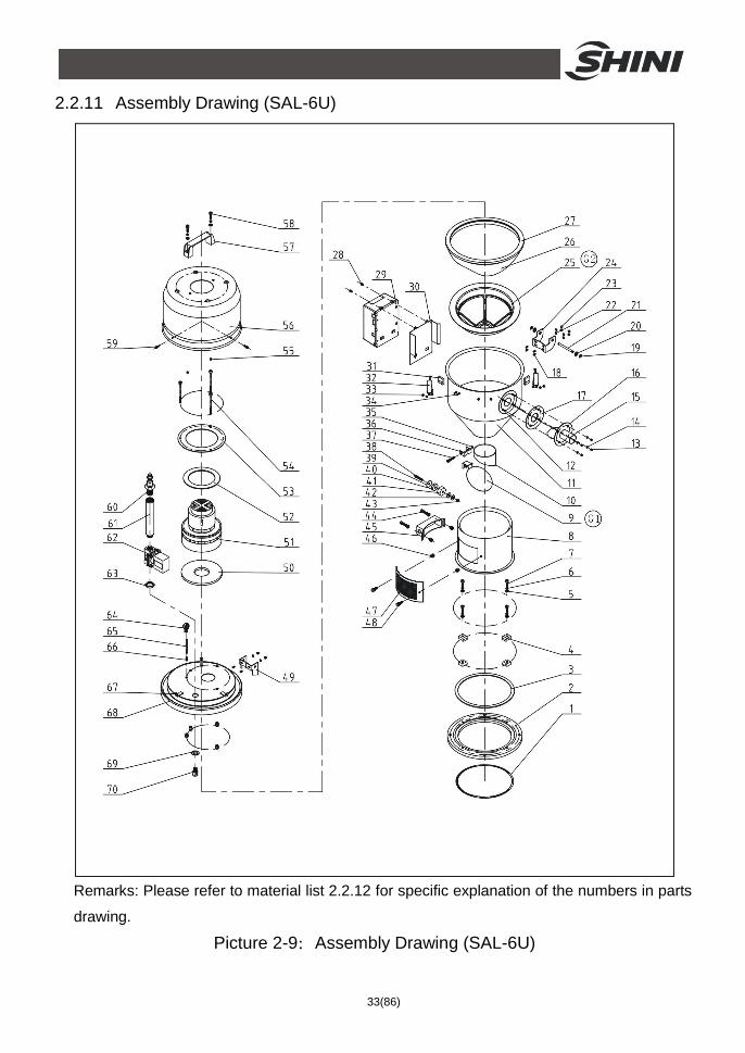
2.2.11 Assembly Drawing (SAL-6U)
Remarks: Please refer to material list 2.2.12 for specific explanation of the numbers in parts
drawing.
Picture 2-9:Assembly Drawing (SAL-6U)
34(86)
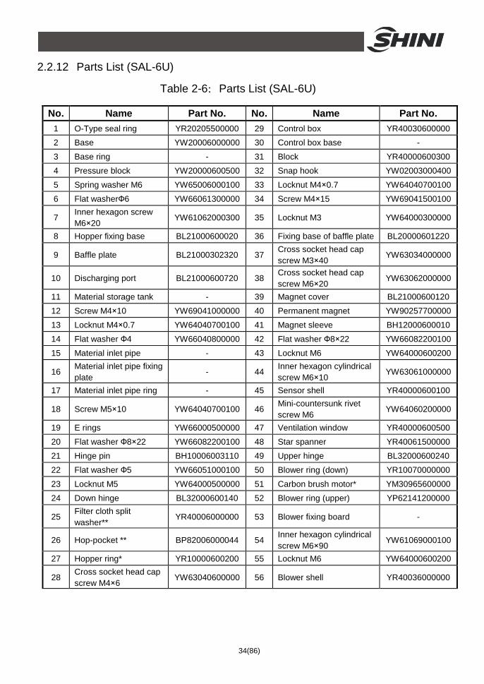
2.2.12 Parts List (SAL-6U)
Table 2-6:Parts List (SAL-6U)
No. Name Part No. No. Name Part No. 1 O-Type seal ring YR20205500000 29 Control box YR40030600000 2 Base YW20006000000 30 Control box base -
3 Base ring - 31 Block YR40000600300
4 Pressure block YW20000600500 32 Snap hook YW02003000400
5 Spring washer M6 YW65006000100 33 Locknut M4×0.7 YW64040700100
6 Flat washerФ6 YW66061300000 34 Screw M4×15 YW69041500100
7 Inner hexagon screw M6×20
YW61062000300 35 Locknut M3 YW64000300000
8 Hopper fixing base BL21000600020 36 Fixing base of baffle plate BL20000601220
9 Baffle plate BL21000302320 37 Cross socket head cap screw M3×40
YW63034000000
10 Discharging port BL21000600720 38 Cross socket head cap screw M6×20
YW63062000000
11 Material storage tank - 39 Magnet cover BL21000600120
12 Screw M4×10 YW69041000000 40 Permanent magnet YW90257700000
13 Locknut M4×0.7 YW64040700100 41 Magnet sleeve BH12000600010
14 Flat washer Ф4 YW66040800000 42 Flat washer Ф8×22 YW66082200100
15 Material inlet pipe - 43 Locknut M6 YW64000600200
16 Material inlet pipe fixing plate
- 44 Inner hexagon cylindrical screw M6×10
YW63061000000
17 Material inlet pipe ring - 45 Sensor shell YR40000600100
18 Screw M5×10 YW64040700100 46 Mini-countersunk rivet screw M6
YW64060200000
19 E rings YW66000500000 47 Ventilation window YR40000600500
20 Flat washer Ф8×22 YW66082200100 48 Star spanner YR40061500000
21 Hinge pin BH10006003110 49 Upper hinge BL32000600240
22 Flat washer Ф5 YW66051000100 50 Blower ring (down) YR10070000000
23 Locknut M5 YW64000500000 51 Carbon brush motor* YM30965600000
24 Down hinge BL32000600140 52 Blower ring (upper) YP62141200000
25 Filter cloth split washer**
YR40006000000 53 Blower fixing board -
26 Hop-pocket ** BP82006000044 54 Inner hexagon cylindrical screw M6×90
YW61069000100
27 Hopper ring* YR10000600200 55 Locknut M6 YW64000600200
28 Cross socket head cap screw M4×6
YW63040600000 56 Blower shell YR40036000000
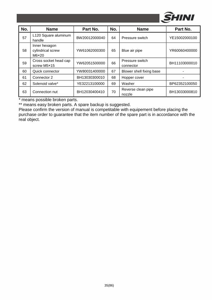
35(86)
No. Name Part No. No. Name Part No.
57 L120 Square aluminum handle
BW20012000040 64 Pressure switch YE15002000100
58 Inner hexagon cylindrical screw M6×20
YW61062000300 65 Blue air pipe YR60060400000
59 Cross socket head cap screw M5×15
YW62051500000 66 Pressure switch connector
BH11103000010
60 Quick connector YW80031400000 67 Blower shell fixing base -
61 Connector 2 BH13030300010 68 Hopper cover -
62 Solenoid valve* YE32213100000 69 Washer BP62352100050
63 Connection nut BH12030400410 70 Reverse clean pipe nozzle
BH13033000810
* means possible broken parts. ** means easy broken parts. A spare backup is suggested. Please confirm the version of manual is competitable with equipement before placing the purchase order to guarantee that the item number of the spare part is in accordance with the real object.
36(86)
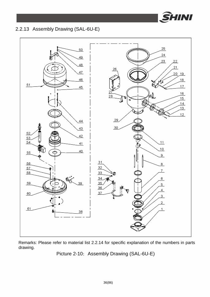
2.2.13 Assembly Drawing (SAL-6U-E)
Remarks: Please refer to material list 2.2.14 for specific explanation of the numbers in parts drawing.
Picture 2-10:Assembly Drawing (SAL-6U-E)
37(86)
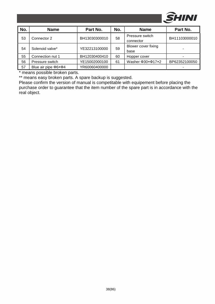
2.2.14 Parts List (SAL-6U-E)
Table 2-7:Parts List (SAL-6U-E)
No. Name Part No. No. Name Part No. 1 Mounting flange BL21060200820 27 Snap hook block YR40000600300
2 3” stainless steel pipe clamp
YW07000300000 28 Snap hook YW02003000400
3 Cap nut M6 YR20802600000 29 Material storage tank -
4 Cap nut M6 YW64006000100 30 Hopper base plate ring
-
5 Glass pipe down flange BW32610900010 31 Set screw M4×5 YW68004500000
6 Glass pipe ring YR10060200000 32 Photosensor fixing base
BL90001000120
7 Glass pipe* YW70317000600 33 Photosensor pressure block
YW31616200000
8 Flange connection shaft BH10000600640 34 Cross socket head cap screw M4×10
YW63041000000
9 Non-return flap - 35 photosensor YE15143900000
10 Discharging port - 36 Photosensor mounting block (come with photosensor)
-
11 Glass pipe upper flange BW32610800010 37 Photosensor fixing plate
BL21061200020
12 Locknut M4×0.7 YW64040700100 38 Reverse clean pipe nozzle
BH13033000810
13 Flat washer 4 YW66040800000 39 Upper hinge BL32000600240 14 Material inlet pipe - 40 Blower ring (down) YR10070000000
15 Material inlet pipe fixing plate
BL20036000320 41 Carbon brush motor 1.15kW
YM30965600000
16 Material inlet pipe ring YR10061200000 42 Blower ring (upper) YP62141200000 17 E-rings 6 YW63051000000 43 Blower fixing board BL21000300420
18 Flat washer M8×22 YW66082200100 44 Inner hexagon cylindrical screw M6×90
YW61069000100
19 Hinge pin BH10006003110 45 Locknut M6 YW64000600200 20 Flat washer 5 YW66051000100 46 Blower shell BL22001200220
21 Locknut M5 YW64000500000 47 Square aluminum handle L120
BW20012000040
22 Down hinge BL32000600140 48 Flat washer 6 YW66061300000 23 Filter cloth split washer** YR40006000000 49 Spring washer 6 YW65006000000
24 Hop-pocket ** BP82003000044 50 Inner hexagon cylindrical screw M6×20
YW61062000300
25 Hopper ring* YR10000300100 51 Cross socket head cap screw M5×15
YW62051500000
26 Control box YR40030600000 52 Quick connector 3” ×1/4PT
YW80031400000
38(86)
No. Name Part No. No. Name Part No.
53 Connector 2 BH13030300010 58 Pressure switch connector
BH11103000010
54 Solenoid valve* YE32213100000 59 Blower cover fixing base
-
55 Connection nut 1 BH12030400410 60 Hopper cover - 56 Pressure switch YE15002000100 61 Washer Ф30×Ф17×2 BP62352100050 57 Blue air pipe Ф6×Ф4 YR60060400000 -
* means possible broken parts. ** means easy broken parts. A spare backup is suggested. Please confirm the version of manual is competitable with equipement before placing the purchase order to guarantee that the item number of the spare part is in accordance with the real object.
39(86)
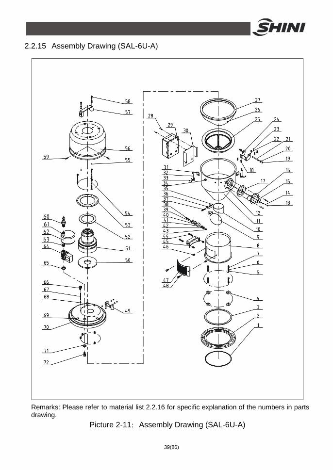
2.2.15 Assembly Drawing (SAL-6U-A)
Remarks: Please refer to material list 2.2.16 for specific explanation of the numbers in parts drawing.
Picture 2-11:Assembly Drawing (SAL-6U-A)
40(86)
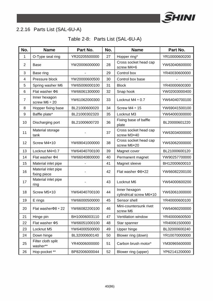
2.2.16 Parts List (SAL-6U-A)
Table 2-8:Parts List (SAL-6U-A)
No. Name Part No. No. Name Part No. 1 O-Type seal ring YR20205500000 27 Hopper ring* YR10000600200
2 Base YW20006000000 28 Cross socket head cap screw M4×6
YW63040600000
3 Base ring - 29 Control box YR40030600000
4 Pressure block YW20000600500 30 Control box base -
5 Spring washer M6 YW65006000100 31 Block YR40000600300
6 Flat washer Ф6 YW66061300000 32 Snap hook YW02003000400
7 Inner hexagon screw M6×20
YW61062000300 33 Locknut M4×0.7 YW64040700100
8 Hopper fixing base BL21000600020 34 Screw M4×15 YW69041500100
9 Baffle plate* BL21000302320 35 Locknut M3 YW64000300000
10 Discharging port BL21000600720 36 Fixing base of baffle plate
BL20000601220
11 Material storage tank
- 37 Cross socket head cap screw M3×40
YW63034000000
12 Screw M4×10 YW69041000000 38 Cross socket head cap screw M6×20
YW63062000000
13 Locknut M4×0.7 YW64040700100 39 Magnet cover BL21000600120
14 Flat washer Ф4 YW66040800000 40 Permanent magnet YW90257700000
15 Material inlet pipe - 41 Magnet sleeve BH12000600010
16 Material inlet pipe fixing piece
- 42 Flat washer Ф8×22 YW66082200100
17 Material inlet pipe ring
- 43 Locknut M6 YW64000600200
18 Screw M5×10 YW64040700100 44 Inner hexagon cylindrical screw M6×10
YW63061000000
19 E rings YW66000500000 45 Sensor shell YR40000600100
20 Flat washerФ8×22 YW66082200100 46 Mini-countersunk rivet screw M6
YW64060200000
21 Hinge pin BH10006003110 47 Ventilation window YR40000600500
22 Flat washer Ф5 YW66051000100 48 Star spanner YR40061500000
23 Locknut M5 YW64000500000 49 Upper hinge BL32000600240
24 Down hinge BL32000600140 50 Blower ring (down) YR10070000000
25 Filter cloth split washer**
YR40006000000 51 Carbon brush motor* YM30965600000
26 Hop-pocket ** BP82006000044 52 Blower ring (upper) YP62141200000
41(86)
No. Name Part No. No. Name Part No. 53 Blower fixing board - 63 Connection nut 2 -
54 Inner hexagon cylindrical screw M6×90
YW61069000100 64 Solenoid valve* YE32213100000
55 Locknut M6 YW64000600200 65 Connection nut BH12030400410
56 Blower shell YR40036000000 66 Pressure switch YE15002000100
57 L120 Square aluminum handle
BW20012000040 67 Blue air pipe YR60060400000
58 Inner hexagon cylindrical screw M6×20
YW61062000300 68 Pressure switch connector
BH11103000010
59 Cross socket head cap screw M5×15
YW62051500000 69 Blower cover fixing base -
60 Quick connector YW80031400000 70 Hopper cover -
61 Connection nut 1 - 71 Washer BP62352100050
62 Air accumulator - 72 Reverse clean pipe nozzle
BH13033000810
* means possible broken parts. ** means easy broken parts. A spare backup is suggested. Please confirm the version of manual is competitable with equipement before placing the purchase order to guarantee that the item number of the spare part is in accordance with the real object.
42(86)
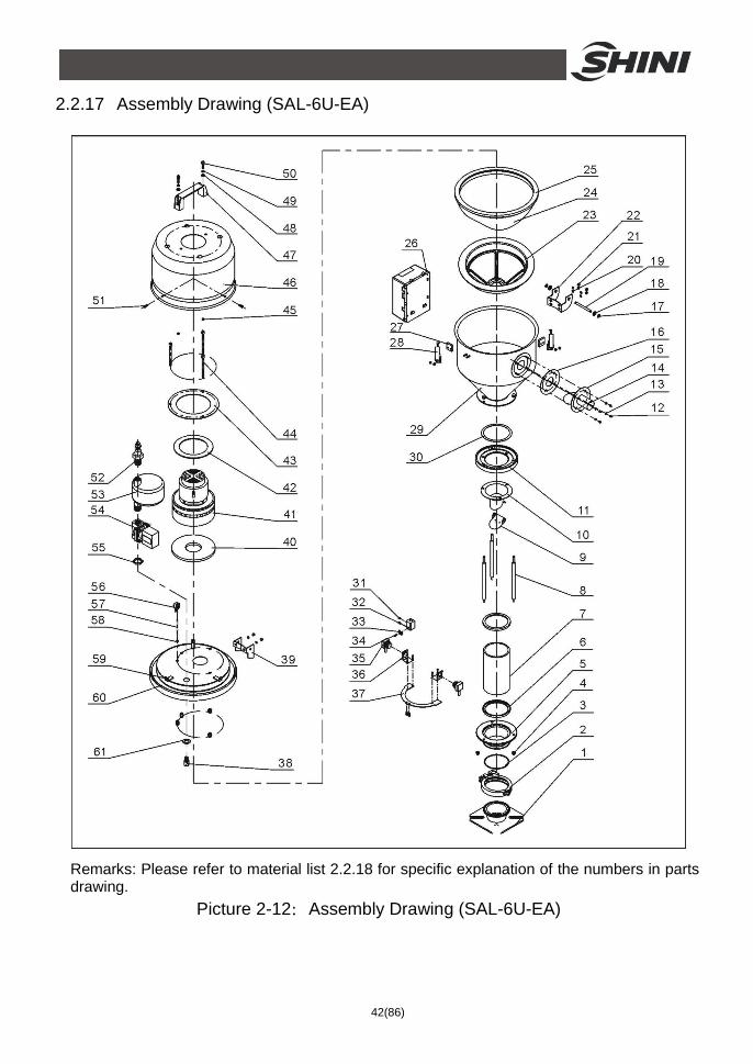
2.2.17 Assembly Drawing (SAL-6U-EA)
Remarks: Please refer to material list 2.2.18 for specific explanation of the numbers in parts drawing.
Picture 2-12:Assembly Drawing (SAL-6U-EA)
43(86)
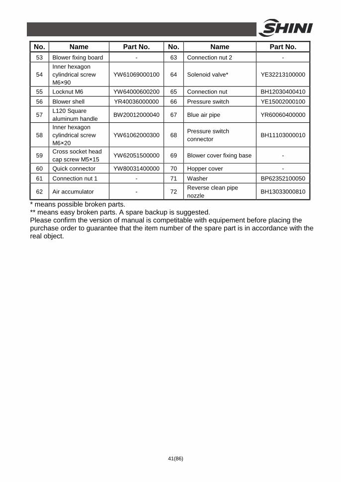
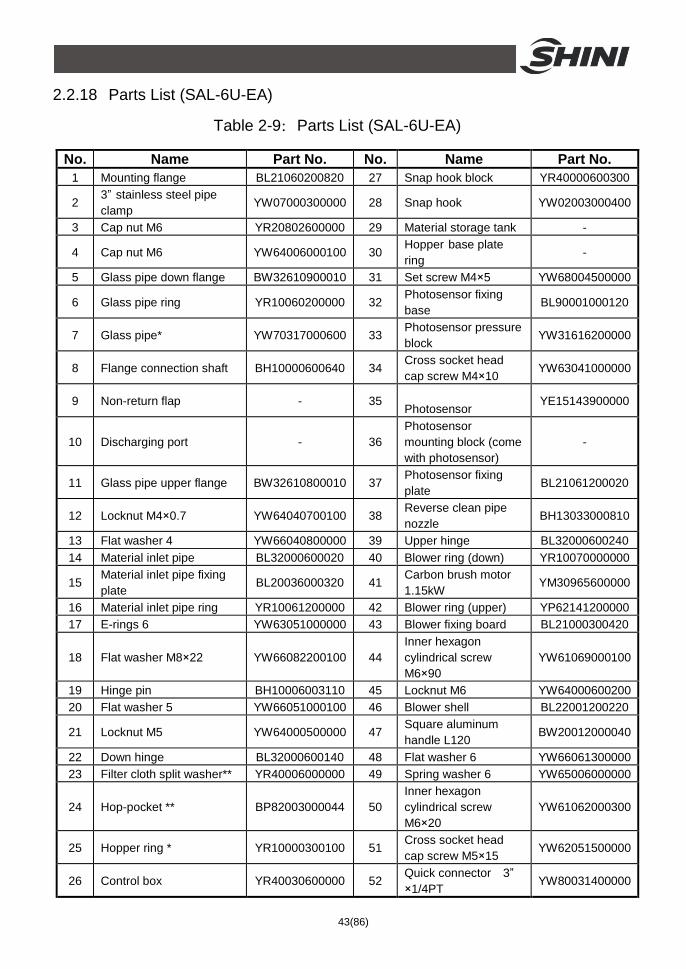
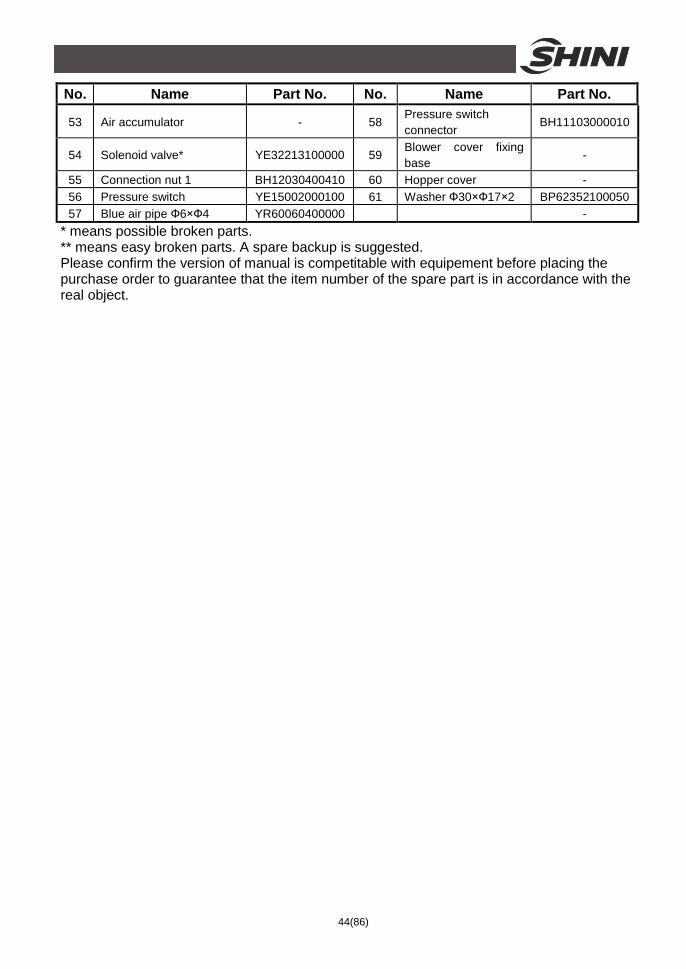
2.2.18 Parts List (SAL-6U-EA)
Table 2-9:Parts List (SAL-6U-EA)
No. Name Part No. No. Name Part No. 1 Mounting flange BL21060200820 27 Snap hook block YR40000600300
2 3” stainless steel pipe clamp
YW07000300000 28 Snap hook YW02003000400
3 Cap nut M6 YR20802600000 29 Material storage tank -
4 Cap nut M6 YW64006000100 30 Hopper base plate ring
-
5 Glass pipe down flange BW32610900010 31 Set screw M4×5 YW68004500000
6 Glass pipe ring YR10060200000 32 Photosensor fixing base
BL90001000120
7 Glass pipe* YW70317000600 33 Photosensor pressure block
YW31616200000
8 Flange connection shaft BH10000600640 34 Cross socket head cap screw M4×10
YW63041000000
9 Non-return flap - 35 Photosensor
YE15143900000
10 Discharging port - 36 Photosensor mounting block (come with photosensor)
-
11 Glass pipe upper flange BW32610800010 37 Photosensor fixing plate
BL21061200020
12 Locknut M4×0.7 YW64040700100 38 Reverse clean pipe nozzle
BH13033000810
13 Flat washer 4 YW66040800000 39 Upper hinge BL32000600240 14 Material inlet pipe BL32000600020 40 Blower ring (down) YR10070000000
15 Material inlet pipe fixing plate
BL20036000320 41 Carbon brush motor 1.15kW
YM30965600000
16 Material inlet pipe ring YR10061200000 42 Blower ring (upper) YP62141200000 17 E-rings 6 YW63051000000 43 Blower fixing board BL21000300420
18 Flat washer M8×22 YW66082200100 44 Inner hexagon cylindrical screw M6×90
YW61069000100
19 Hinge pin BH10006003110 45 Locknut M6 YW64000600200 20 Flat washer 5 YW66051000100 46 Blower shell BL22001200220
21 Locknut M5 YW64000500000 47 Square aluminum handle L120
BW20012000040
22 Down hinge BL32000600140 48 Flat washer 6 YW66061300000 23 Filter cloth split washer** YR40006000000 49 Spring washer 6 YW65006000000
24 Hop-pocket ** BP82003000044 50 Inner hexagon cylindrical screw M6×20
YW61062000300
25 Hopper ring * YR10000300100 51 Cross socket head cap screw M5×15
YW62051500000
26 Control box YR40030600000 52 Quick connector 3” ×1/4PT
YW80031400000
44(86)
No. Name Part No. No. Name Part No.
53 Air accumulator - 58 Pressure switch connector
BH11103000010
54 Solenoid valve* YE32213100000 59 Blower cover fixing base
-
55 Connection nut 1 BH12030400410 60 Hopper cover - 56 Pressure switch YE15002000100 61 Washer Ф30×Ф17×2 BP62352100050 57 Blue air pipe Ф6×Ф4 YR60060400000 -
* means possible broken parts. ** means easy broken parts. A spare backup is suggested. Please confirm the version of manual is competitable with equipement before placing the purchase order to guarantee that the item number of the spare part is in accordance with the real object.
45(86)
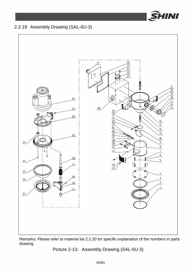
2.2.19 Assembly Drawing (SAL-6U-3)
Remarks: Please refer to material list 2.2.20 for specific explanation of the numbers in parts drawing.
Picture 2-13:Assembly Drawing (SAL-6U-3)
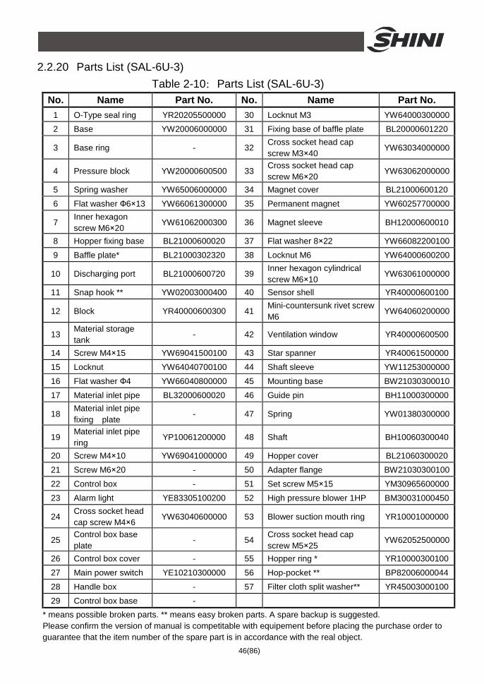
46(86)
2.2.20 Parts List (SAL-6U-3) Table 2-10:Parts List (SAL-6U-3)
No. Name Part No. No. Name Part No. 1 O-Type seal ring YR20205500000 30 Locknut M3 YW64000300000 2 Base YW20006000000 31 Fixing base of baffle plate BL20000601220
3 Base ring - 32 Cross socket head cap screw M3×40
YW63034000000
4 Pressure block YW20000600500 33 Cross socket head cap screw M6×20
YW63062000000
5 Spring washer YW65006000000 34 Magnet cover BL21000600120
6 Flat washer Ф6×13 YW66061300000 35 Permanent magnet YW60257700000
7 Inner hexagon screw M6×20
YW61062000300 36 Magnet sleeve BH12000600010
8 Hopper fixing base BL21000600020 37 Flat washer 8×22 YW66082200100
9 Baffle plate* BL21000302320 38 Locknut M6 YW64000600200
10 Discharging port BL21000600720 39 Inner hexagon cylindrical screw M6×10
YW63061000000
11 Snap hook ** YW02003000400 40 Sensor shell YR40000600100
12 Block YR40000600300 41 Mini-countersunk rivet screw M6
YW64060200000
13 Material storage tank
- 42 Ventilation window YR40000600500
14 Screw M4×15 YW69041500100 43 Star spanner YR40061500000
15 Locknut YW64040700100 44 Shaft sleeve YW11253000000
16 Flat washer Ф4 YW66040800000 45 Mounting base BW21030300010
17 Material inlet pipe BL32000600020 46 Guide pin BH11000300000
18 Material inlet pipe fixing plate
- 47 Spring YW01380300000
19 Material inlet pipe ring
YP10061200000 48 Shaft BH10060300040
20 Screw M4×10 YW69041000000 49 Hopper cover BL21060300020
21 Screw M6×20 - 50 Adapter flange BW21030300100
22 Control box - 51 Set screw M5×15 YM30965600000
23 Alarm light YE83305100200 52 High pressure blower 1HP BM30031000450
24 Cross socket head cap screw M4×6
YW63040600000 53 Blower suction mouth ring YR10001000000
25 Control box base plate
- 54 Cross socket head cap screw M5×25
YW62052500000
26 Control box cover - 55 Hopper ring * YR10000300100
27 Main power switch YE10210300000 56 Hop-pocket ** BP82006000044
28 Handle box - 57 Filter cloth split washer** YR45003000100
29 Control box base - * means possible broken parts. ** means easy broken parts. A spare backup is suggested. Please confirm the version of manual is competitable with equipement before placing the purchase order to guarantee that the item number of the spare part is in accordance with the real object.
47(86)
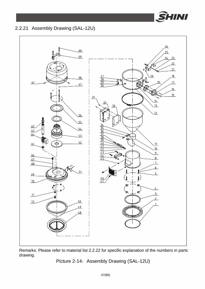
2.2.21 Assembly Drawing (SAL-12U)
Remarks: Please refer to material list 2.2.22 for specific explanation of the numbers in parts drawing.
Picture 2-14:Assembly Drawing (SAL-12U)
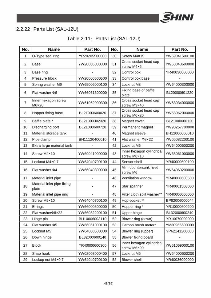
48(86)
2.2.22 Parts List (SAL-12U)
Table 2-11:Parts List (SAL-12U)
No. Name Part No. No. Name Part No. 1 O-Type seal ring YR20205500000 30 Screw M4×15 YW69041500100
2 Base YW20006000000 31 Cross socket head cap screw M4×6
YW63040600000
3 Base ring - 32 Control box YR40030600000
4 Pressure block YW20000600500 33 Control box base -
5 Spring washer M6 YW65006000100 34 Locknut M3 YW64000300000
6 Flat washer Ф6 YW66061300000 35 Fixing base of baffle plate
BL20000601220
7 Inner hexagon screw M6×20
YW61062000300 36 Cross socket head cap screw M3×40
YW63034000000
8 Hopper fixing base BL21000600020 37 Cross socket head cap screw M6×20
YW63062000000
9 Baffle plate * BL21000302320 38 Magnet cover BL21000600120
10 Discharging port BL21000600720 39 Permanent magnet YW90257700000
11 Material storage tank - 40 Magnet sleeve BH12000600010
12 Pipe clamp BH11120400010 41 Flat washer Ф8×22 YW66082200100
13 Extra large material tank - 42 Locknut M6 YW64000600200
14 Screw M4×10 YW69041000000 43 Inner hexagon cylindrical screw M6×10
YW63061000000
15 Locknut M4×0.7 YW64040700100 44 Sensor shell YR40000600100
16 Flat washer Ф4 YW66040800000 45 Mini-countersunk rivet screw M6
YW64060200000
17 Material inlet pipe - 46 Ventilation window YR40000600500
18 Material inlet pipe fixing plate
- 47 Star spanner YR40061500000
19 Material inlet pipe ring - 48 Filter cloth split washer** YR40006000000
20 Screw M5×10 YW64040700100 49 Hop-pocket ** BP82006000044
21 E rings YW66000500000 50 Hopper ring * YR10000600200
22 Flat washerФ8×22 YW66082200100 51 Upper hinge BL32000600240
23 Hinge pin BH10006003110 52 Blower ring (down) YR10070000000
24 Flat washer Ф5 YW66051000100 53 Carbon brush motor* YM30965600000
25 Locknut M5 YW64000500000 54 Blower ring (upper) YP62141200000
26 Down hinge BL32000600140 55 Blower fixing board -
27 Block YR40000600300 56 Inner hexagon cylindrical screw M6×90
YW61069000100
28 Snap hook YW02003000400 57 Locknut M6 YW64000600200
29 Lockup nut M4×0.7 YW64040700100 58 Blower shell YR40036000000
49(86)
No. Name Part No. No. Name Part No.
59 L120 Square aluminum handle
BW20012000040 66 Pressure switch YE15002000100
60 Inner hexagon cylindrical screw M6×20
YW61062000300 67 Blue air pipe YR60060400000
61 Cross socket head cap screw M5×15
YW62051500000 68 Pressure switch connector
BH11103000010
62 Quick connector YW80031400000 69 Blower cover fixing base -
63 Connector 2 BH13030300010 70 Hopper cover -
64 Solenoid valve* YE32213100000 71 Washer BP62352100050
65 Connection nut BH12030400410 72 Reverse clean pipe nozzle
BH13033000810
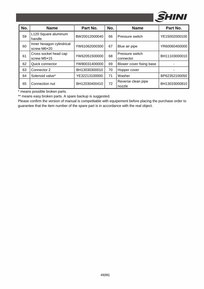
* means possible broken parts. ** means easy broken parts. A spare backup is suggested. Please confirm the version of manual is competitable with equipement before placing the purchase order to guarantee that the item number of the spare part is in accordance with the real object.
50(86)
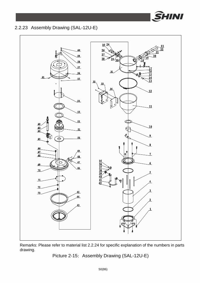
2.2.23 Assembly Drawing (SAL-12U-E)
Remarks: Please refer to material list 2.2.24 for specific explanation of the numbers in parts drawing.
Picture 2-15:Assembly Drawing (SAL-12U-E)
51(86)
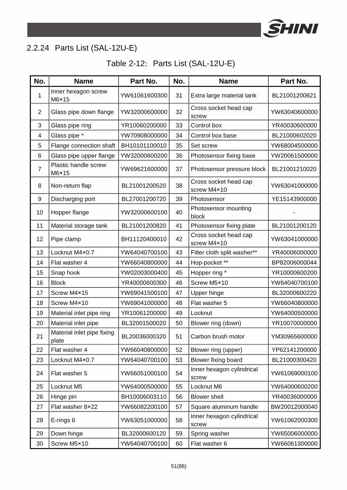
2.2.24 Parts List (SAL-12U-E)
Table 2-12:Parts List (SAL-12U-E)
No. Name Part No. No. Name Part No.
1 Inner hexagon screw M6×15
YW61061600300 31 Extra large material tank BL21001200621
2 Glass pipe down flange YW32000600000 32 Cross socket head cap screw
YW63040600000
3 Glass pipe ring YR10060200000 33 Control box YR40030600000
4 Glass pipe * YW70908000000 34 Control box base BL21000602020
5 Flange connection shaft BH10101100010 35 Set screw YW68004500000
6 Glass pipe upper flange YW32000600200 36 Photosensor fixing base YW20061500000
7 Plastic handle screw M6×15
YW69621600000 37 Photosensor pressure block BL21001210020
8 Non-return flap BL21001200520 38 Cross socket head cap screw M4×10
YW63041000000
9 Discharging port BL27001200720 39 Photosensor YE15143900000
10 Hopper flange YW32000600100 40 Photosensor mounting block
-
11 Material storage tank BL21001200820 41 Photosensor fixing plate BL21001200120
12 Pipe clamp BH11120400010 42 Cross socket head cap screw M4×10
YW63041000000
13 Locknut M4×0.7 YW64040700100 43 Filter cloth split washer** YR40006000000
14 Flat washer 4 YW66040800000 44 Hop-pocket ** BP82006000044
15 Snap hook YW02003000400 45 Hopper ring * YR10000600200
16 Block YR40000600300 46 Screw M5×10 YW64040700100
17 Screw M4×15 YW69041500100 47 Upper hinge BL32000600220
18 Screw M4×10 YW69041000000 48 Flat washer 5 YW66040800000
19 Material inlet pipe ring YR10061200000 49 Locknut YW64000500000
20 Material inlet pipe BL32001500020 50 Blower ring (down) YR10070000000
21 Material inlet pipe fixing plate
BL20036000320 51 Carbon brush motor YM30965600000
22 Flat washer 4 YW66040800000 52 Blower ring (upper) YP62141200000
23 Locknut M4×0.7 YW64040700100 53 Blower fixing board BL21000300420
24 Flat washer 5 YW66051000100 54 Inner hexagon cylindrical screw
YW61069000100
25 Locknut M5 YW64000500000 55 Locknut M6 YW64000600200
26 Hinge pin BH10006003110 56 Blower shell YR40036000000
27 Flat washer 8×22 YW66082200100 57 Square aluminum handle BW20012000040
28 E-rings 6 YW63051000000 58 Inner hexagon cylindrical screw
YW61062000300
29 Down hinge BL32000600120 59 Spring washer YW65006000000
30 Screw M5×10 YW64040700100 60 Flat washer 6 YW66061300000
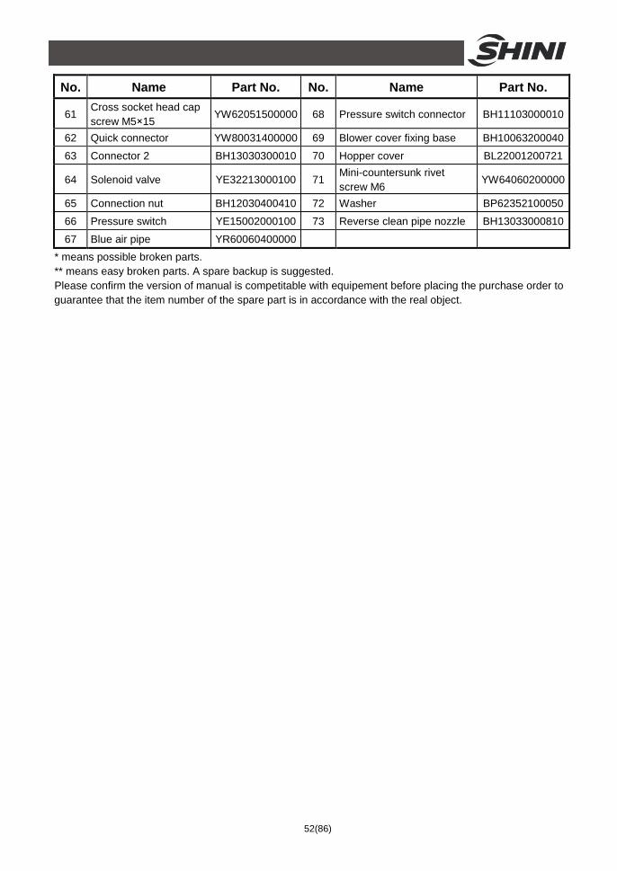
52(86)
No. Name Part No. No. Name Part No.
61 Cross socket head cap screw M5×15
YW62051500000 68 Pressure switch connector BH11103000010
62 Quick connector YW80031400000 69 Blower cover fixing base BH10063200040
63 Connector 2 BH13030300010 70 Hopper cover BL22001200721
64 Solenoid valve YE32213000100 71 Mini-countersunk rivet screw M6
YW64060200000
65 Connection nut BH12030400410 72 Washer BP62352100050
66 Pressure switch YE15002000100 73 Reverse clean pipe nozzle BH13033000810
67 Blue air pipe YR60060400000 * means possible broken parts. ** means easy broken parts. A spare backup is suggested. Please confirm the version of manual is competitable with equipement before placing the purchase order to guarantee that the item number of the spare part is in accordance with the real object.
53(86)
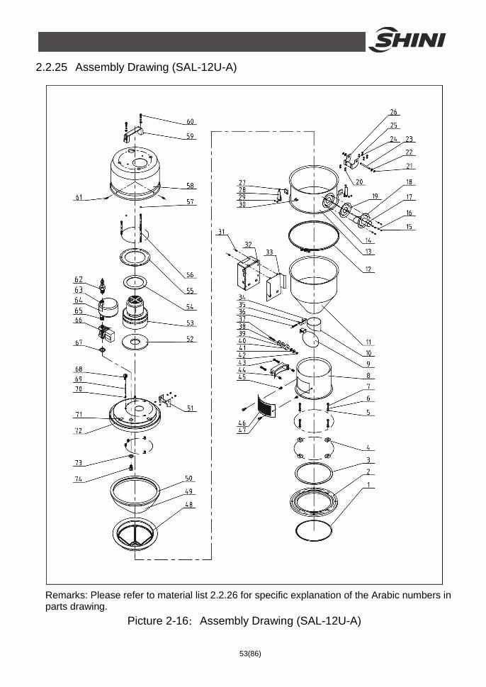
2.2.25 Assembly Drawing (SAL-12U-A)
Remarks: Please refer to material list 2.2.26 for specific explanation of the Arabic numbers in parts drawing.
Picture 2-16:Assembly Drawing (SAL-12U-A)
54(86)
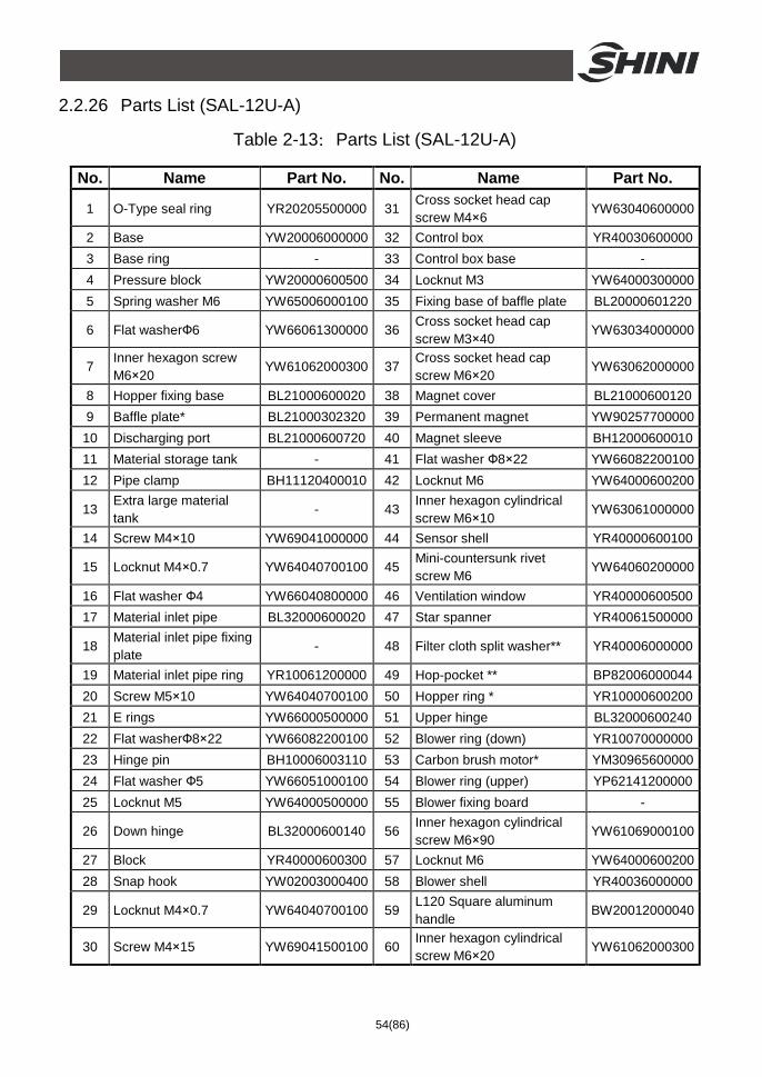
2.2.26 Parts List (SAL-12U-A)
Table 2-13:Parts List (SAL-12U-A)
No. Name Part No. No. Name Part No.
1 O-Type seal ring YR20205500000 31 Cross socket head cap screw M4×6
YW63040600000
2 Base YW20006000000 32 Control box YR40030600000 3 Base ring - 33 Control box base - 4 Pressure block YW20000600500 34 Locknut M3 YW64000300000 5 Spring washer M6 YW65006000100 35 Fixing base of baffle plate BL20000601220
6 Flat washerФ6 YW66061300000 36 Cross socket head cap screw M3×40
YW63034000000
7 Inner hexagon screw M6×20
YW61062000300 37 Cross socket head cap screw M6×20
YW63062000000
8 Hopper fixing base BL21000600020 38 Magnet cover BL21000600120 9 Baffle plate* BL21000302320 39 Permanent magnet YW90257700000
10 Discharging port BL21000600720 40 Magnet sleeve BH12000600010 11 Material storage tank - 41 Flat washer Ф8×22 YW66082200100 12 Pipe clamp BH11120400010 42 Locknut M6 YW64000600200
13 Extra large material tank
- 43 Inner hexagon cylindrical screw M6×10
YW63061000000
14 Screw M4×10 YW69041000000 44 Sensor shell YR40000600100
15 Locknut M4×0.7 YW64040700100 45 Mini-countersunk rivet screw M6
YW64060200000
16 Flat washer Ф4 YW66040800000 46 Ventilation window YR40000600500 17 Material inlet pipe BL32000600020 47 Star spanner YR40061500000
18 Material inlet pipe fixing plate
- 48 Filter cloth split washer** YR40006000000
19 Material inlet pipe ring YR10061200000 49 Hop-pocket ** BP82006000044 20 Screw M5×10 YW64040700100 50 Hopper ring * YR10000600200 21 E rings YW66000500000 51 Upper hinge BL32000600240 22 Flat washerФ8×22 YW66082200100 52 Blower ring (down) YR10070000000 23 Hinge pin BH10006003110 53 Carbon brush motor* YM30965600000 24 Flat washer Ф5 YW66051000100 54 Blower ring (upper) YP62141200000 25 Locknut M5 YW64000500000 55 Blower fixing board -
26 Down hinge BL32000600140 56 Inner hexagon cylindrical screw M6×90
YW61069000100
27 Block YR40000600300 57 Locknut M6 YW64000600200 28 Snap hook YW02003000400 58 Blower shell YR40036000000
29 Locknut M4×0.7 YW64040700100 59 L120 Square aluminum handle
BW20012000040
30 Screw M4×15 YW69041500100 60 Inner hexagon cylindrical screw M6×20
YW61062000300
55(86)
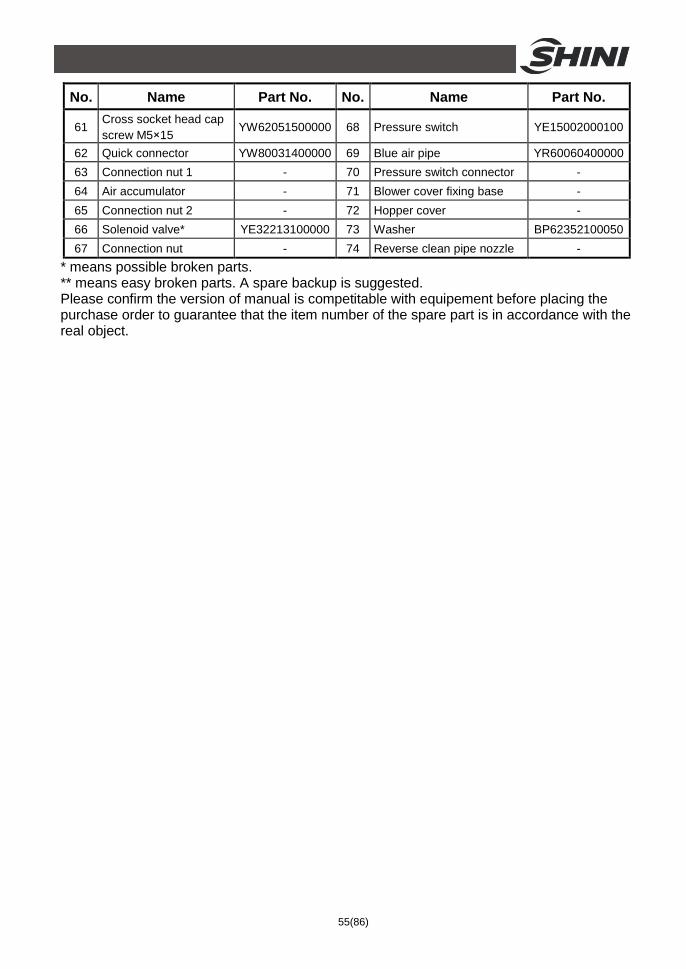
No. Name Part No. No. Name Part No.
61 Cross socket head cap screw M5×15
YW62051500000 68 Pressure switch YE15002000100
62 Quick connector YW80031400000 69 Blue air pipe YR60060400000 63 Connection nut 1 - 70 Pressure switch connector - 64 Air accumulator - 71 Blower cover fixing base - 65 Connection nut 2 - 72 Hopper cover - 66 Solenoid valve* YE32213100000 73 Washer BP62352100050 67 Connection nut - 74 Reverse clean pipe nozzle -
* means possible broken parts. ** means easy broken parts. A spare backup is suggested. Please confirm the version of manual is competitable with equipement before placing the purchase order to guarantee that the item number of the spare part is in accordance with the real object.
56(86)
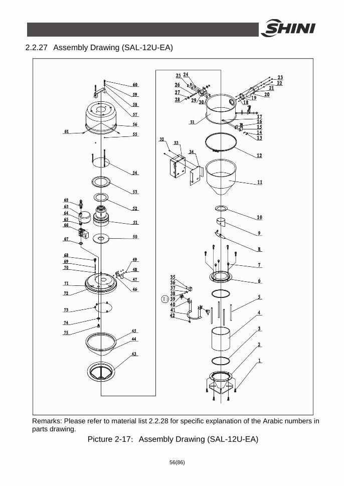
2.2.27 Assembly Drawing (SAL-12U-EA)
Remarks: Please refer to material list 2.2.28 for specific explanation of the Arabic numbers in parts drawing.
Picture 2-17:Assembly Drawing (SAL-12U-EA)
57(86)
2.2.28 Parts List (SAL-12U-EA)
Table 2-14:Parts List (SAL-12U-EA)
No. Name Part No. No. Name Part No.
1 Inner hexagon screw M6×15
YW61061600300 31 Extra large material tank BL21001200621
2 Glass pipe down flange YW32000600000 32 Cross socket head cap screw
YW63040600000
3 Glass pipe ring YR10060200000 33 Control box YR40030600000
4 Glass pipe * YW70908000000 34 Control box base BL21000602020
5 Flange connection shaft BH10101100010 35 Set screw YW68004500000
6 Glass pipe upper flange YW32000600200 36 Photosensor fixing base YW20061500000
7 Plastic handle screw M6×15
YW69621600000 37 Photosensor pressure block BL21001210020
8 Non-return flap BL21001200520 38 Cross socket head cap screw M4×10
YW63041000000
9 Discharging port BL27001200720 39 Photosensor YE15143900000
10 Hopper flange YW32000600100 40 Photosensor mounting block
-
11 Material storage tank BL21001200820 41 Photosensor fixing plate BL21001200120
12 Pipe clamp BH11120400010 42 Cross socket head cap screw M4×10
YW63041000000
13 Locknut M4×0.7 YW64040700100 43 Filter cloth split washer** YR40006000000
14 Flat washer 4 YW66040800000 44 Hop-pocket ** BP82006000044
15 Snap hook YW02003000400 45 Hopper ring * YR10000600200
16 Block YR40000600300 46 Screw M5×10 YW64040700100
17 Screw M4×15 YW69041500100 47 Upper hinge BL32000600220
18 Screw M4×10 YW69041000000 48 Flat washer 5 YW66040800000
19 Material inlet pipe ring YR10061200000 49 Locknut YW64000500000
20 Material inlet pipe BL32001500020 50 Blower ring (down) YR10070000000
21 Material inlet pipe fixing plate
BL20036000320 51 Carbon brush motor YM30965600000
22 Flat washer 4 YW66040800000 52 Blower ring (upper) YP62141200000
23 Locknut M4×0.7 YW64040700100 53 Blower fixing board BL21000300420
24 Flat washer 5 YW66051000100 54 Inner hexagon cylindrical screw M6×90
YW61069000100
25 Locknut M5 YW64000500000 55 Locknut M6 YW64000600200
26 Hinge pin BH10006003110 56 Blower shell YR40036000000
27 Flat washer 8×22 YW66082200100 57 Square aluminum handle BW20012000040
28 E-rings 6 YW63051000000 58 Inner hexagon cylindrical screw M6×20
YW61062000300
29 Down hinge BL32000600120 59 Spring washer YW65006000000
30 Screw M5×10 YW64040700100 60 Flat washer 6 YW66061300000
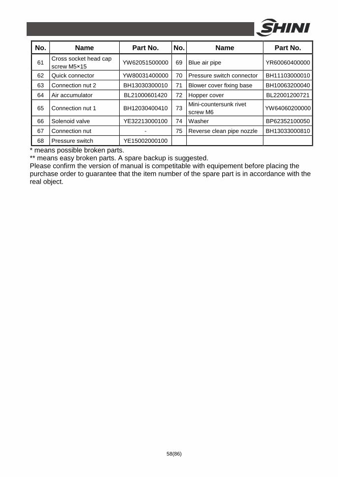
58(86)
No. Name Part No. No. Name Part No.
61 Cross socket head cap screw M5×15
YW62051500000 69 Blue air pipe YR60060400000
62 Quick connector YW80031400000 70 Pressure switch connector BH11103000010
63 Connection nut 2 BH13030300010 71 Blower cover fixing base BH10063200040
64 Air accumulator BL21000601420 72 Hopper cover BL22001200721
65 Connection nut 1 BH12030400410 73 Mini-countersunk rivet screw M6
YW64060200000
66 Solenoid valve YE32213000100 74 Washer BP62352100050
67 Connection nut - 75 Reverse clean pipe nozzle BH13033000810
68 Pressure switch YE15002000100 * means possible broken parts. ** means easy broken parts. A spare backup is suggested. Please confirm the version of manual is competitable with equipement before placing the purchase order to guarantee that the item number of the spare part is in accordance with the real object.
59(86)
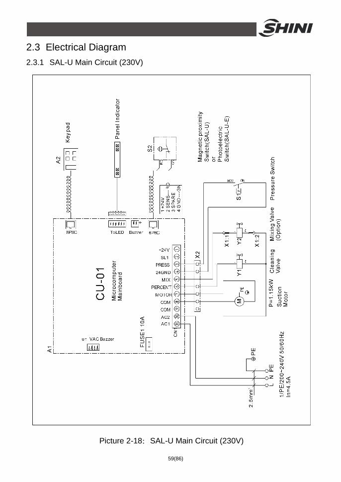
2.3 Electrical Diagram 2.3.1 SAL-U Main Circuit (230V)
Picture 2-18:SAL-U Main Circuit (230V)
60(86)
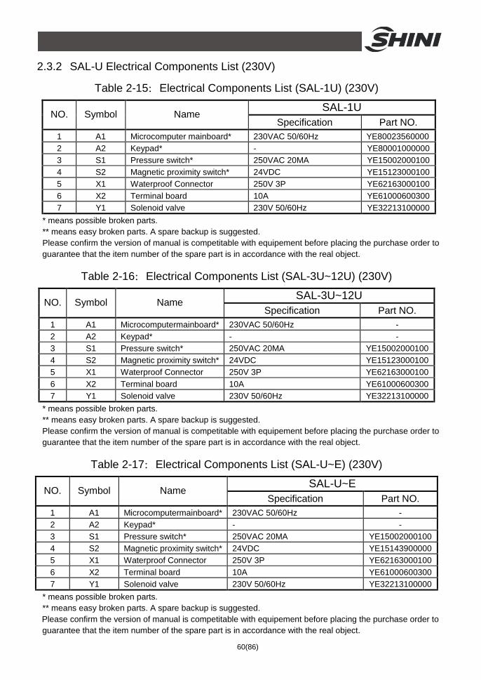
2.3.2 SAL-U Electrical Components List (230V)
Table 2-15:Electrical Components List (SAL-1U) (230V)
SAL-1U NO. Symbol Name
Specification Part NO. 1 A1 Microcomputer mainboard* 230VAC 50/60Hz YE80023560000 2 A2 Keypad* - YE80001000000 3 S1 Pressure switch* 250VAC 20MA YE15002000100 4 S2 Magnetic proximity switch* 24VDC YE15123000100 5 X1 Waterproof Connector 250V 3P YE62163000100 6 X2 Terminal board 10A YE61000600300 7 Y1 Solenoid valve 230V 50/60Hz YE32213100000
* means possible broken parts. ** means easy broken parts. A spare backup is suggested. Please confirm the version of manual is competitable with equipement before placing the purchase order to guarantee that the item number of the spare part is in accordance with the real object.
Table 2-16:Electrical Components List (SAL-3U~12U) (230V)
SAL-3U~12U NO. Symbol Name
Specification Part NO. 1 A1 Microcomputermainboard* 230VAC 50/60Hz - 2 A2 Keypad* - - 3 S1 Pressure switch* 250VAC 20MA YE15002000100 4 S2 Magnetic proximity switch* 24VDC YE15123000100 5 X1 Waterproof Connector 250V 3P YE62163000100 6 X2 Terminal board 10A YE61000600300 7 Y1 Solenoid valve 230V 50/60Hz YE32213100000
* means possible broken parts. ** means easy broken parts. A spare backup is suggested. Please confirm the version of manual is competitable with equipement before placing the purchase order to guarantee that the item number of the spare part is in accordance with the real object.
Table 2-17:Electrical Components List (SAL-U~E) (230V)
SAL-U~E NO. Symbol Name
Specification Part NO. 1 A1 Microcomputermainboard* 230VAC 50/60Hz - 2 A2 Keypad* - - 3 S1 Pressure switch* 250VAC 20MA YE15002000100 4 S2 Magnetic proximity switch* 24VDC YE15143900000 5 X1 Waterproof Connector 250V 3P YE62163000100 6 X2 Terminal board 10A YE61000600300 7 Y1 Solenoid valve 230V 50/60Hz YE32213100000
* means possible broken parts. ** means easy broken parts. A spare backup is suggested. Please confirm the version of manual is competitable with equipement before placing the purchase order to guarantee that the item number of the spare part is in accordance with the real object.
61(86)
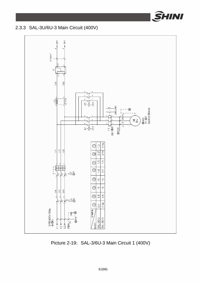
2.3.3 SAL-3U/6U-3 Main Circuit (400V)
Picture 2-19:SAL-3/6U-3 Main Circuit 1 (400V)

62(86)
Picture 2-20:SAL-3/6U-3 Main Circuit 2 (400V)
63(86)
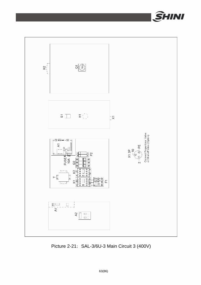
Picture 2-21:SAL-3/6U-3 Main Circuit 3 (400V)
64(86)
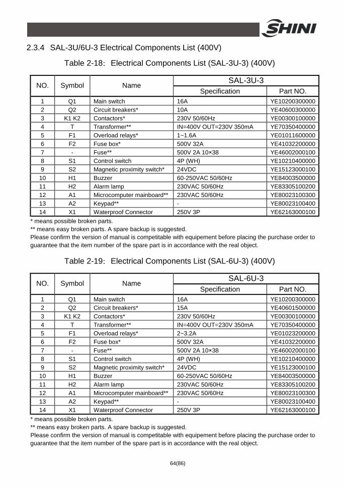
2.3.4 SAL-3U/6U-3 Electrical Components List (400V)
Table 2-18:Electrical Components List (SAL-3U-3) (400V)
SAL-3U-3 NO. Symbol Name
Specification Part NO. 1 Q1 Main switch 16A YE10200300000 2 Q2 Circuit breakers* 10A YE40600300000 3 K1 K2 Contactors* 230V 50/60Hz YE00300100000 4 T Transformer** IN=400V OUT=230V 350mA YE70350400000 5 F1 Overload relays* 1~1.6A YE01011600000 6 F2 Fuse box* 500V 32A YE41032200000 7 - Fuse** 500V 2A 10×38 YE46002000100 8 S1 Control switch 4P (WH) YE10210400000 9 S2 Magnetic proximity switch* 24VDC YE15123000100
10 H1 Buzzer 60-250VAC 50/60Hz YE84003500000 11 H2 Alarm lamp 230VAC 50/60Hz YE83305100200 12 A1 Microcomputer mainboard** 230VAC 50/60Hz YE80023100300 13 A2 Keypad** - YE80023100400 14 X1 Waterproof Connector 250V 3P YE62163000100
* means possible broken parts. ** means easy broken parts. A spare backup is suggested. Please confirm the version of manual is competitable with equipement before placing the purchase order to guarantee that the item number of the spare part is in accordance with the real object.
Table 2-19:Electrical Components List (SAL-6U-3) (400V)
SAL-6U-3 NO. Symbol Name
Specification Part NO. 1 Q1 Main switch 16A YE10200300000 2 Q2 Circuit breakers* 15A YE40601500000 3 K1 K2 Contactors* 230V 50/60Hz YE00300100000 4 T Transformer** IN=400V OUT=230V 350mA YE70350400000 5 F1 Overload relays* 2~3.2A YE01023200000 6 F2 Fuse box* 500V 32A YE41032200000 7 - Fuse** 500V 2A 10×38 YE46002000100 8 S1 Control switch 4P (WH) YE10210400000 9 S2 Magnetic proximity switch* 24VDC YE15123000100
10 H1 Buzzer 60-250VAC 50/60Hz YE84003500000 11 H2 Alarm lamp 230VAC 50/60Hz YE83305100200 12 A1 Microcomputer mainboard** 230VAC 50/60Hz YE80023100300 13 A2 Keypad** - YE80023100400 14 X1 Waterproof Connector 250V 3P YE62163000100
* means possible broken parts. ** means easy broken parts. A spare backup is suggested. Please confirm the version of manual is competitable with equipement before placing the purchase order to guarantee that the item number of the spare part is in accordance with the real object.
65(86)
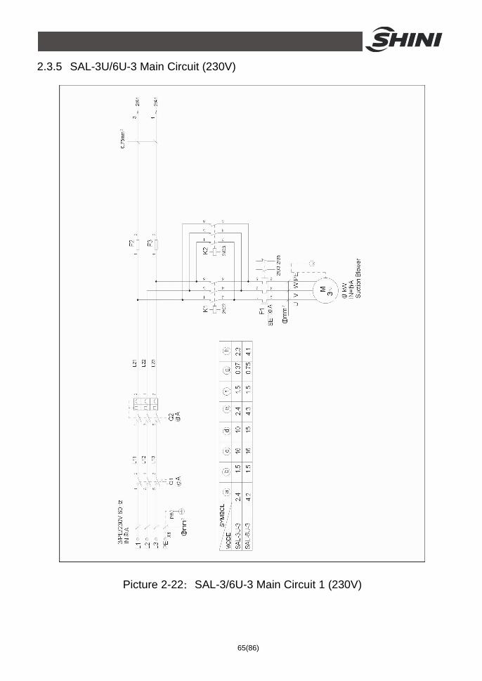
2.3.5 SAL-3U/6U-3 Main Circuit (230V)
Picture 2-22:SAL-3/6U-3 Main Circuit 1 (230V)
66(86)
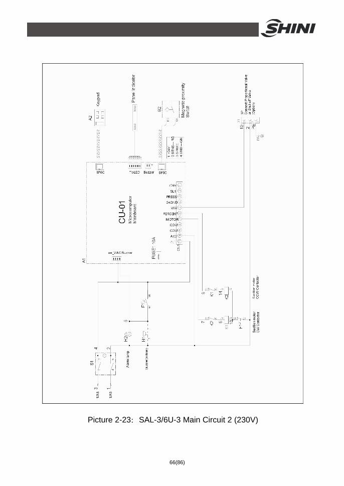
Picture 2-23:SAL-3/6U-3 Main Circuit 2 (230V)
67(86)
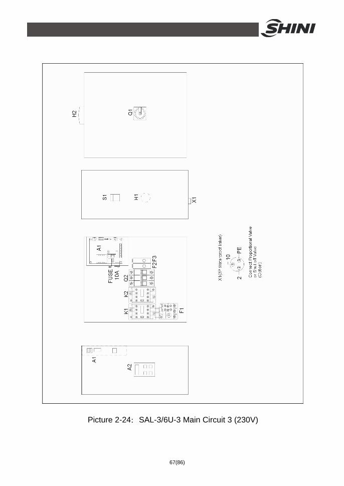
Picture 2-24:SAL-3/6U-3 Main Circuit 3 (230V)
68(86)
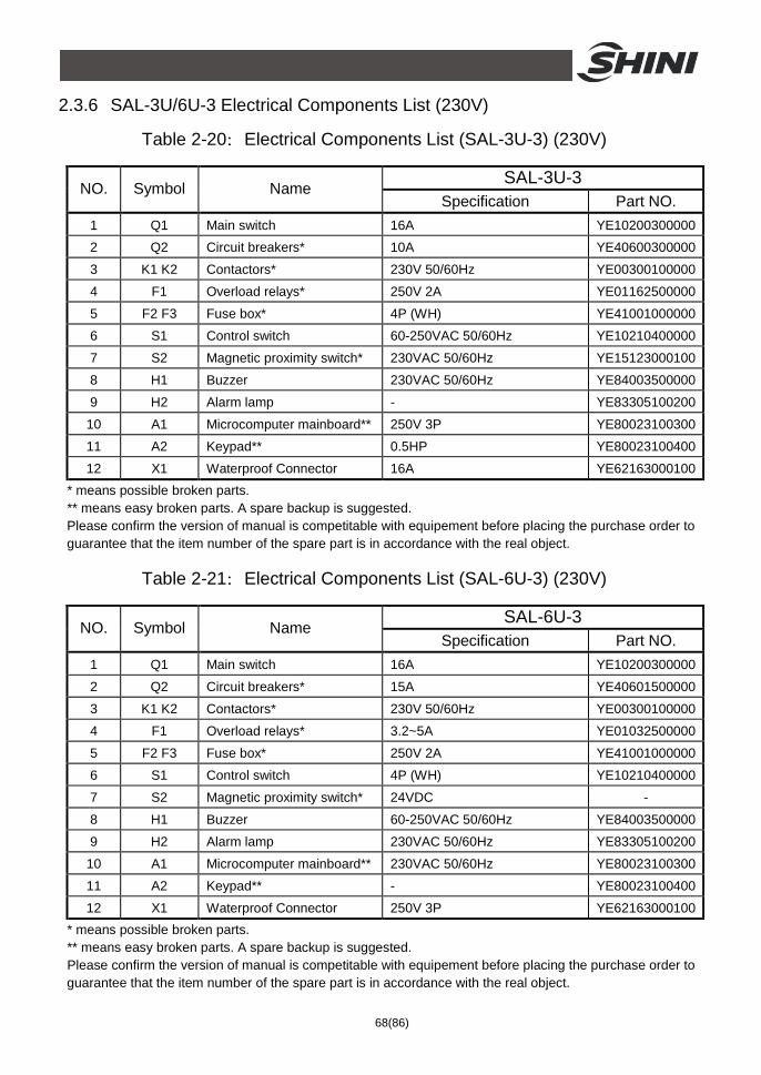
2.3.6 SAL-3U/6U-3 Electrical Components List (230V)
Table 2-20:Electrical Components List (SAL-3U-3) (230V)
SAL-3U-3 NO. Symbol Name
Specification Part NO. 1 Q1 Main switch 16A YE10200300000 2 Q2 Circuit breakers* 10A YE40600300000
3 K1 K2 Contactors* 230V 50/60Hz YE00300100000
4 F1 Overload relays* 250V 2A YE01162500000
5 F2 F3 Fuse box* 4P (WH) YE41001000000
6 S1 Control switch 60-250VAC 50/60Hz YE10210400000
7 S2 Magnetic proximity switch* 230VAC 50/60Hz YE15123000100
8 H1 Buzzer 230VAC 50/60Hz YE84003500000
9 H2 Alarm lamp - YE83305100200
10 A1 Microcomputer mainboard** 250V 3P YE80023100300
11 A2 Keypad** 0.5HP YE80023100400
12 X1 Waterproof Connector 16A YE62163000100 * means possible broken parts. ** means easy broken parts. A spare backup is suggested. Please confirm the version of manual is competitable with equipement before placing the purchase order to guarantee that the item number of the spare part is in accordance with the real object.
Table 2-21:Electrical Components List (SAL-6U-3) (230V)
SAL-6U-3 NO. Symbol Name
Specification Part NO. 1 Q1 Main switch 16A YE10200300000
2 Q2 Circuit breakers* 15A YE40601500000
3 K1 K2 Contactors* 230V 50/60Hz YE00300100000
4 F1 Overload relays* 3.2~5A YE01032500000
5 F2 F3 Fuse box* 250V 2A YE41001000000
6 S1 Control switch 4P (WH) YE10210400000
7 S2 Magnetic proximity switch* 24VDC -
8 H1 Buzzer 60-250VAC 50/60Hz YE84003500000
9 H2 Alarm lamp 230VAC 50/60Hz YE83305100200
10 A1 Microcomputer mainboard** 230VAC 50/60Hz YE80023100300
11 A2 Keypad** - YE80023100400
12 X1 Waterproof Connector 250V 3P YE62163000100 * means possible broken parts. ** means easy broken parts. A spare backup is suggested. Please confirm the version of manual is competitable with equipement before placing the purchase order to guarantee that the item number of the spare part is in accordance with the real object.
69(86)
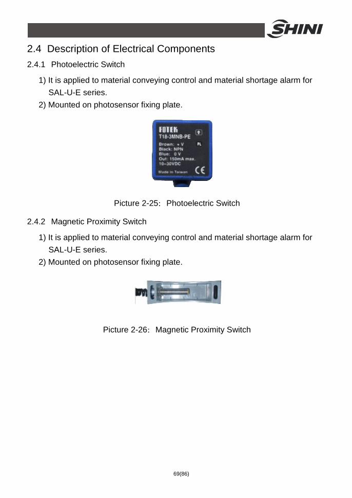
2.4 Description of Electrical Components 2.4.1 Photoelectric Switch
1) It is applied to material conveying control and material shortage alarm for SAL-U-E series.
2) Mounted on photosensor fixing plate.
Picture 2-25:Photoelectric Switch
2.4.2 Magnetic Proximity Switch
1) It is applied to material conveying control and material shortage alarm for SAL-U-E series.
2) Mounted on photosensor fixing plate.
Picture 2-26:Magnetic Proximity Switch
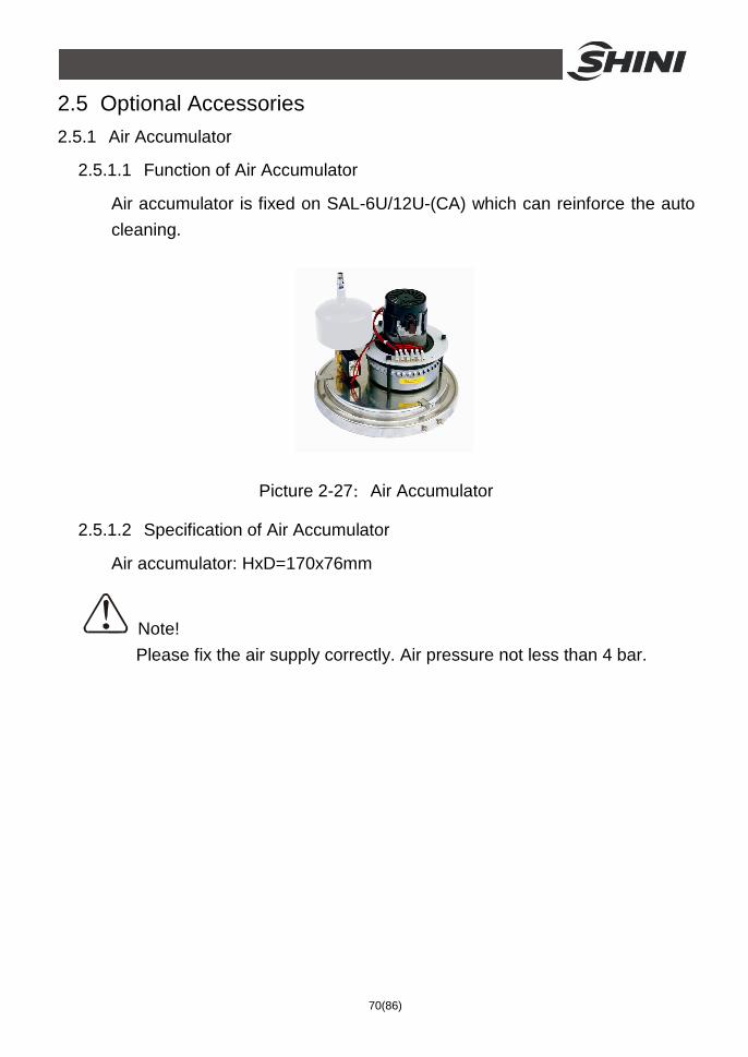
70(86)
2.5 Optional Accessories 2.5.1 Air Accumulator
2.5.1.1 Function of Air Accumulator
Air accumulator is fixed on SAL-6U/12U-(CA) which can reinforce the auto cleaning.
Picture 2-27:Air Accumulator
2.5.1.2 Specification of Air Accumulator
Air accumulator: HxD=170x76mm
Note! Please fix the air supply correctly. Air pressure not less than 4 bar.
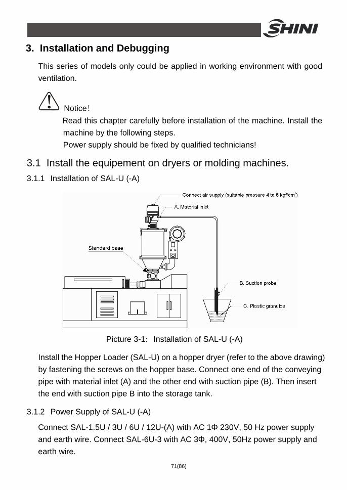
71(86)
3. Installation and Debugging This series of models only could be applied in working environment with good ventilation.
Notice! Read this chapter carefully before installation of the machine. Install the machine by the following steps. Power supply should be fixed by qualified technicians!
3.1 Install the equipement on dryers or molding machines. 3.1.1 Installation of SAL-U (-A)
Picture 3-1:Installation of SAL-U (-A)
Install the Hopper Loader (SAL-U) on a hopper dryer (refer to the above drawing) by fastening the screws on the hopper base. Connect one end of the conveying pipe with material inlet (A) and the other end with suction pipe (B). Then insert the end with suction pipe B into the storage tank.
3.1.2 Power Supply of SAL-U (-A)
Connect SAL-1.5U / 3U / 6U / 12U-(A) with AC 1Φ 230V, 50 Hz power supply and earth wire. Connect SAL-6U-3 with AC 3Φ, 400V, 50Hz power supply and earth wire.
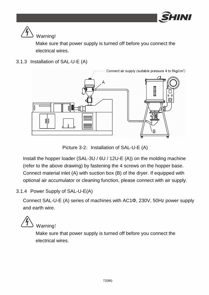
72(86)
Warning! Make sure that power supply is turned off before you connect the electrical wires.
3.1.3 Installation of SAL-U-E (A)
Picture 3-2:Installation of SAL-U-E (A)
Install the hopper loader (SAL-3U / 6U / 12U-E (A)) on the molding machine (refer to the above drawing) by fastening the 4 screws on the hopper base. Connect material inlet (A) with suction box (B) of the dryer. If equipped with optional air accumulator or cleaning function, please connect with air supply.
3.1.4 Power Supply of SAL-U-E(A)
Connect SAL-U-E (A) series of machines with AC1Φ, 230V, 50Hz power supply and earth wire.
Warning! Make sure that power supply is turned off before you connect the electrical wires.
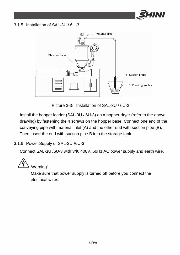
73(86)
3.1.5 Installation of SAL-3U / 6U-3
Picture 3-3:Installation of SAL-3U / 6U-3
Install the hopper loader (SAL-3U / 6U-3) on a hopper dryer (refer to the above drawing) by fastening the 4 screws on the hopper base. Connect one end of the conveying pipe with material inlet (A) and the other end with suction pipe (B). Then insert the end with suction pipe B into the storage tank.
3.1.6 Power Supply of SAL-3U /6U-3
Connect SAL-3U /6U-3 with 3Φ, 400V, 50Hz AC power supply and earth wire.
Warning! Make sure that power supply is turned off before you connect the electrical wires.
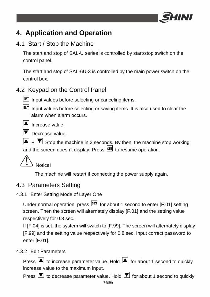
74(86)
4. Application and Operation 4.1 Start / Stop the Machine
The start and stop of SAL-U series is controlled by start/stop switch on the control panel.
The start and stop of SAL-6U-3 is controlled by the main power switch on the control box.
4.2 Keypad on the Control Panel Input values before selecting or canceling items.
Input values before selecting or saving items. It is also used to clear the alarm when alarm occurs.
Increase value.
Decrease value.
+ Stop the machine in 3 seconds. By then, the machine stop working and the screen doesn’t display. Press to resume operation.
Notice!
The machine will restart if connecting the power supply again.
4.3 Parameters Setting 4.3.1 Enter Setting Mode of Layer One
Under normal operation, press for about 1 second to enter [F.01] setting screen. Then the screen will alternately display [F.01] and the setting value respectively for 0.8 sec. If [F.04] is set, the system will switch to [F.99]. The screen will alternately display [F.99] and the setting value respectively for 0.8 sec. Input correct password to enter [F.01].
4.3.2 Edit Parameters
Press to increase parameter value. Hold for about 1 second to quickly increase value to the maximum input. Press to decrease parameter value. Hold for about 1 second to quickly
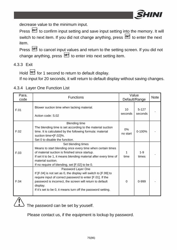
75(86)
decrease value to the minimum input. Press to confirm input setting and save input setting into the memory. It will switch to next item. If you did not change anything, press to enter the next item. Press to cancel input values and return to the setting screen. If you did not change anything, press to enter into next setting item.
4.3.3 Exit
Hold for 1 second to return to default display. If no input for 20 seconds, it will return to default display without saving changes.
4.3.4 Layer One Function List
Para. code Functions Value
Default/Range Note
F.01 Blower suction time when lacking material. Action code: S.02
10 seconds
5-127 seconds
-
F.02
Blending time The blending time is set according to the material suction time. It is calculated by the following formula: material suction time×[F.02]%. Set 0 to disable the function.
0% no start
0-100% -
F.03
Set blending times Means to start blending once every time when certain times of material suction is finished since startup. If set it to be 1, it means blending material after every time of material suction. If no require of blending, set [F.02] to be 0.
1 time
1-9 times
-
F.04
Password Layer One If [F.04] is not set as 0, the display will switch to [F.99] to require input of correct password to enter [F.01]. If the password is incorrect, the screen will return to default display. If it’s set to be 0, it means turn off the password setting.
0 0-999 -
The password can be set by youself.
Please contact us, if the equipment is lockup by password.
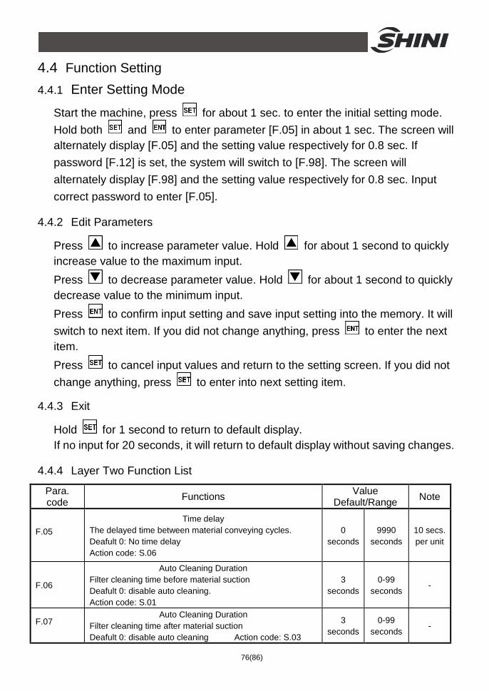
76(86)
4.4 Function Setting 4.4.1 Enter Setting Mode
Start the machine, press for about 1 sec. to enter the initial setting mode. Hold both and to enter parameter [F.05] in about 1 sec. The screen will alternately display [F.05] and the setting value respectively for 0.8 sec. If password [F.12] is set, the system will switch to [F.98]. The screen will alternately display [F.98] and the setting value respectively for 0.8 sec. Input correct password to enter [F.05].
4.4.2 Edit Parameters
Press to increase parameter value. Hold for about 1 second to quickly increase value to the maximum input. Press to decrease parameter value. Hold for about 1 second to quickly decrease value to the minimum input. Press to confirm input setting and save input setting into the memory. It will switch to next item. If you did not change anything, press to enter the next item. Press to cancel input values and return to the setting screen. If you did not change anything, press to enter into next setting item.
4.4.3 Exit
Hold for 1 second to return to default display. If no input for 20 seconds, it will return to default display without saving changes.
4.4.4 Layer Two Function List
Para. code Functions Value
Default/Range Note
F.05 Time delay
The delayed time between material conveying cycles. Deafult 0: No time delay Action code: S.06
0 seconds
9990 seconds
10 secs. per unit
F.06
Auto Cleaning Duration Filter cleaning time before material suction Deafult 0: disable auto cleaning. Action code: S.01
3 seconds
0-99 seconds
-
F.07 Auto Cleaning Duration
Filter cleaning time after material suction Deafult 0: disable auto cleaning Action code: S.03
3 seconds
0-99 seconds
-
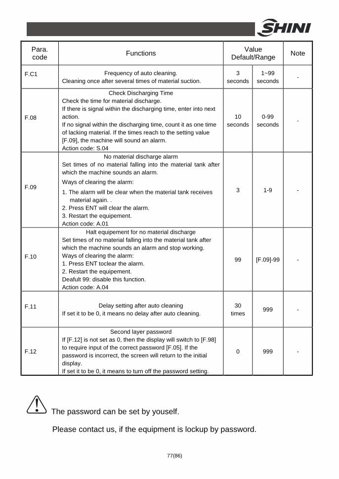
77(86)
Para. code Functions Value
Default/Range Note
F.C1 Frequency of auto cleaning. Cleaning once after several times of material suction.
3 seconds
1~99 seconds
-
F.08
Check Discharging Time Check the time for material discharge. If there is signal within the discharging time, enter into next action. If no signal within the discharging time, count it as one time of lacking material. If the times reach to the setting value [F.09], the machine will sound an alarm. Action code: S.04
10 seconds
0-99 seconds
-
F.09
No material discharge alarm Set times of no material falling into the material tank after which the machine sounds an alarm. Ways of clearing the alarm:
1. The alarm will be clear when the material tank receives material again. .
2. Press ENT will clear the alarm. 3. Restart the equipement. Action code: A.01
3 1-9 -
F.10
Halt equipement for no material discharge Set times of no material falling into the material tank after which the machine sounds an alarm and stop working. Ways of clearing the alarm: 1. Press ENT toclear the alarm. 2. Restart the equipement. Deafult 99: disable this function. Action code: A.04
99 [F.09]-99 -
F.11 Delay setting after auto cleaning If set it to be 0, it means no delay after auto cleaning.
30 times
999 -
F.12
Second layer password If [F.12] is not set as 0, then the display will switch to [F.98] to require input of the correct password [F.05]. If the password is incorrect, the screen will return to the initial display. If set it to be 0, it means to turn off the password setting.
0 999 -
The password can be set by youself.
Please contact us, if the equipment is lockup by password.
78(86)
4.5 Function Setting: Special Process 4.5.1 Enter special process setting Mode
Enter setting mode according to the steps descripped in 6.4. Press to choose [F.11]; then keep holding and then press for about 1 sec. to enter into the setting of [F.13]. The screen will alternately display [F.13] and the setting value respectively for 0.8 sec.
4.5.2 Edit Parameters
Press to increase parameter value. Hold for about 1 second to quickly increase value to the maximum input. Press to decrease parameter value. Hold for about 1 second to quickly decrease value to the minimum input. Press to confirm input setting and save input setting into the memory. It will switch to next item. If you did not change anything, press to enter the next item. Press to cancel input values and return to the setting screen. If you did not change anything, press to enter into next setting item.
4.5.3 Exit
Hold for 1 second to return to default display. If no input for 20 seconds, it will return to default display without saving changes.
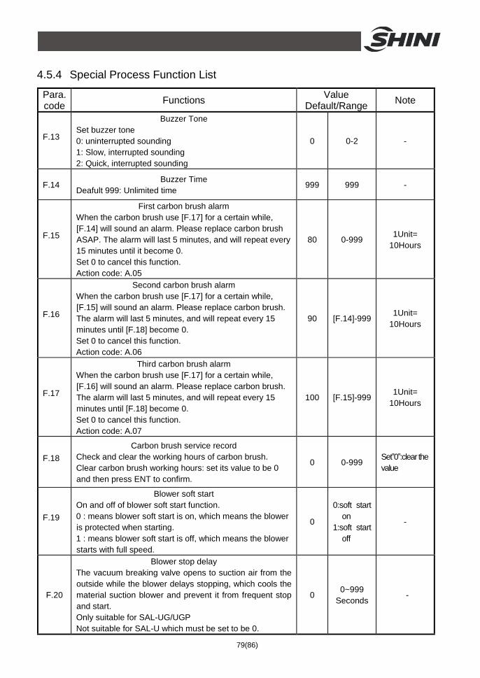
79(86)
4.5.4 Special Process Function List
Para. code Functions Value
Default/Range Note
F.13
Buzzer Tone Set buzzer tone 0: uninterrupted sounding 1: Slow, interrupted sounding 2: Quick, interrupted sounding
0 0-2 -
F.14 Buzzer Time
Deafult 999: Unlimited time 999 999 -
F.15
First carbon brush alarm When the carbon brush use [F.17] for a certain while, [F.14] will sound an alarm. Please replace carbon brush ASAP. The alarm will last 5 minutes, and will repeat every 15 minutes until it become 0. Set 0 to cancel this function. Action code: A.05
80 0-999 1Unit=
10Hours
F.16
Second carbon brush alarm When the carbon brush use [F.17] for a certain while, [F.15] will sound an alarm. Please replace carbon brush. The alarm will last 5 minutes, and will repeat every 15 minutes until [F.18] become 0. Set 0 to cancel this function. Action code: A.06
90 [F.14]-999 1Unit=
10Hours
F.17
Third carbon brush alarm When the carbon brush use [F.17] for a certain while, [F.16] will sound an alarm. Please replace carbon brush. The alarm will last 5 minutes, and will repeat every 15 minutes until [F.18] become 0. Set 0 to cancel this function. Action code: A.07
100 [F.15]-999 1Unit=
10Hours
F.18 Carbon brush service record
Check and clear the working hours of carbon brush. Clear carbon brush working hours: set its value to be 0 and then press ENT to confirm.
0 0-999 Set”0”:clear the value
F.19
Blower soft start On and off of blower soft start function. 0 : means blower soft start is on, which means the blower is protected when starting. 1 : means blower soft start is off, which means the blower starts with full speed.
0
0:soft start on
1:soft start off
-
F.20
Blower stop delay The vacuum breaking valve opens to suction air from the outside while the blower delays stopping, which cools the material suction blower and prevent it from frequent stop and start. Only suitable for SAL-UG/UGP Not suitable for SAL-U which must be set to be 0.
0 0~999
Seconds -
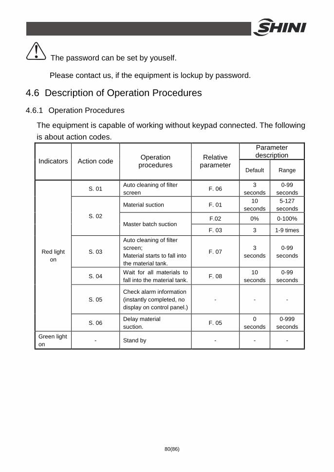
80(86)
The password can be set by youself.
Please contact us, if the equipment is lockup by password.
4.6 Description of Operation Procedures
4.6.1 Operation Procedures
The equipment is capable of working without keypad connected. The following is about action codes.
Parameter description
Indicators Action code Operation procedures
Relative parameter
Default Range
S. 01 Auto cleaning of filter screen
F. 06 3
seconds 0-99
seconds
Material suction F. 01 10
seconds 5-127
seconds
F.02 0% 0-100% S. 02 Master batch suction
F. 03 3 1-9 times
S. 03
Auto cleaning of filter screen; Material starts to fall into the material tank.
F. 07 3
seconds 0-99
seconds
S. 04 Wait for all materials to fall into the material tank.
F. 08 10
seconds 0-99
seconds
S. 05 Check alarm information (instantly completed, no display on control panel.)
- - -
Red light on
S. 06 Delay material suction.
F. 05 0
seconds 0-999
seconds
Green light on
- Stand by - - -
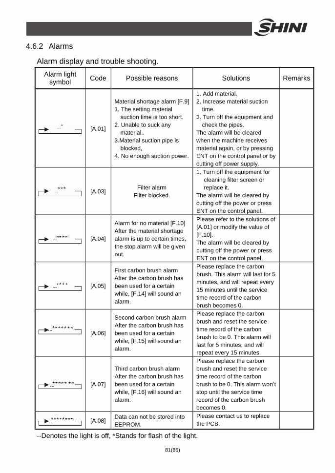
81(86)
4.6.2 Alarms
Alarm display and trouble shooting. Alarm light
symbol Code Possible reasons Solutions Remarks
[A.01]
Material shortage alarm [F.9] 1. The setting material
suction time is too short. 2. Unable to suck any
material.. 3.Material suction pipe is
blocked, 4. No enough suction power.
1. Add material. 2. Increase material suction
time. 3. Turn off the equipment and
check the pipes. The alarm will be cleared when the machine receives material again, or by pressing ENT on the control panel or by cutting off power supply.
[A.03] Filter alarm
Filter blocked.
1. Turn off the equipment for cleaning filter screen or replace it.
The alarm will be cleared by cutting off the power or press ENT on the control panel.
[A.04]
Alarm for no material [F.10] After the material shortage alarm is up to certain times, the stop alarm will be given out.
Please refer to the solutions of [A.01] or modify the value of [F.10]. The alarm will be cleared by cutting off the power or press ENT on the control panel.
[A.05]
First carbon brush alarm After the carbon brush has been used for a certain while, [F.14] will sound an alarm.
Please replace the carbon brush. This alarm will last for 5 minutes, and will repeat every 15 minutes until the service time record of the carbon brush becomes 0.
[A.06]
Second carbon brush alarm After the carbon brush has been used for a certain while, [F.15] will sound an alarm.
Please replace the carbon brush and reset the service time record of the carbon brush to be 0. This alarm will last for 5 minutes, and will repeat every 15 minutes.
[A.07]
Third carbon brush alarm After the carbon brush has been used for a certain while, [F.16] will sound an alarm.
Please replace the carbon brush and reset the service time record of the carbon brush to be 0. This alarm won’t stop until the service time record of the carbon brush becomes 0.
[A.08] Data can not be stored into EEPROM.
Please contact us to replace the PCB.
--Denotes the light is off, *Stands for flash of the light.
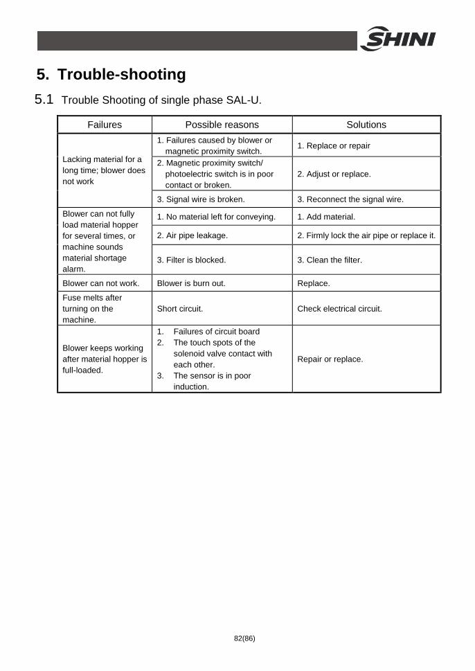
82(86)
5. Trouble-shooting 5.1 Trouble Shooting of single phase SAL-U.
Failures Possible reasons Solutions 1. Failures caused by blower or
magnetic proximity switch. 1. Replace or repair
2. Magnetic proximity switch/ photoelectric switch is in poor contact or broken.
2. Adjust or replace.
Lacking material for a long time; blower does not work
3. Signal wire is broken. 3. Reconnect the signal wire.
1. No material left for conveying. 1. Add material.
2. Air pipe leakage. 2. Firmly lock the air pipe or replace it.
Blower can not fully load material hopper for several times, or machine sounds material shortage alarm.
3. Filter is blocked. 3. Clean the filter.
Blower can not work. Blower is burn out. Replace.
Fuse melts after turning on the machine.
Short circuit. Check electrical circuit.
Blower keeps working after material hopper is full-loaded.
1. Failures of circuit board 2. The touch spots of the
solenoid valve contact with each other.
3. The sensor is in poor induction.
Repair or replace.
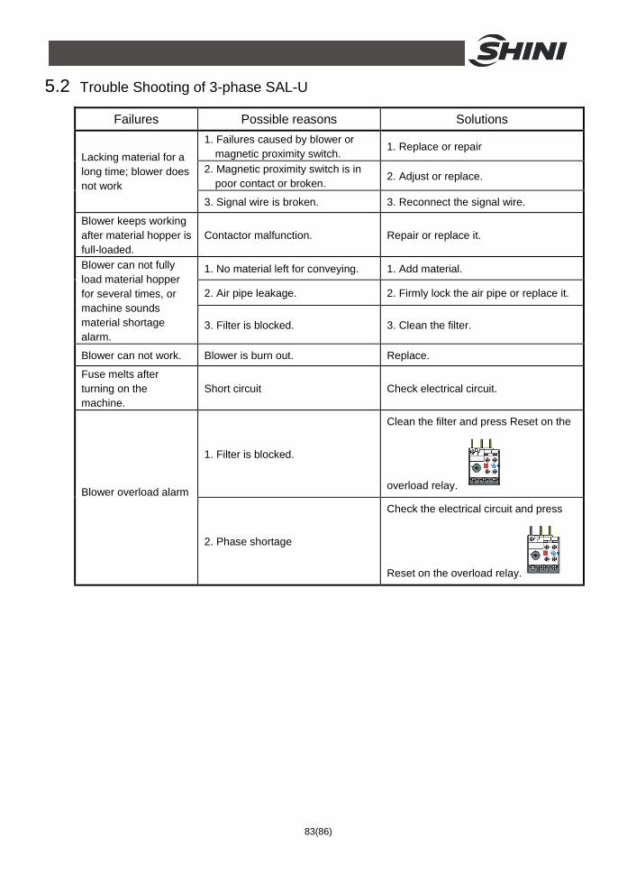
83(86)
5.2 Trouble Shooting of 3-phase SAL-U
Failures Possible reasons Solutions 1. Failures caused by blower or
magnetic proximity switch. 1. Replace or repair
2. Magnetic proximity switch is in poor contact or broken.
2. Adjust or replace.
Lacking material for a long time; blower does not work
3. Signal wire is broken. 3. Reconnect the signal wire.
Blower keeps working after material hopper is full-loaded.
Contactor malfunction. Repair or replace it.
1. No material left for conveying. 1. Add material.
2. Air pipe leakage. 2. Firmly lock the air pipe or replace it.
Blower can not fully load material hopper for several times, or machine sounds material shortage alarm.
3. Filter is blocked. 3. Clean the filter.
Blower can not work. Blower is burn out. Replace.
Fuse melts after turning on the machine.
Short circuit Check electrical circuit.
1. Filter is blocked.
Clean the filter and press Reset on the
overload relay. Blower overload alarm
2. Phase shortage
Check the electrical circuit and press
Reset on the overload relay.
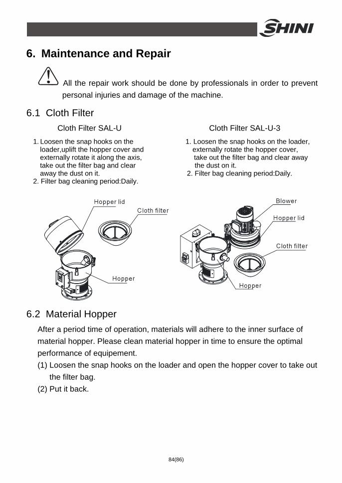
84(86)
6. Maintenance and Repair
All the repair work should be done by professionals in order to prevent personal injuries and damage of the machine.
6.1 Cloth Filter Cloth Filter SAL-U Cloth Filter SAL-U-3
1. Loosen the snap hooks on the 1. Loosen the snap hooks on the loader, loader,uplift the hopper cover and externally rotate the hopper cover, externally rotate it along the axis, take out the filter bag and clear away take out the filter bag and clear the dust on it. away the dust on it. 2. Filter bag cleaning period:Daily. 2. Filter bag cleaning period:Daily.
6.2 Material Hopper After a period time of operation, materials will adhere to the inner surface of material hopper. Please clean material hopper in time to ensure the optimal performance of equipement. (1) Loosen the snap hooks on the loader and open the hopper cover to take out
the filter bag. (2) Put it back.
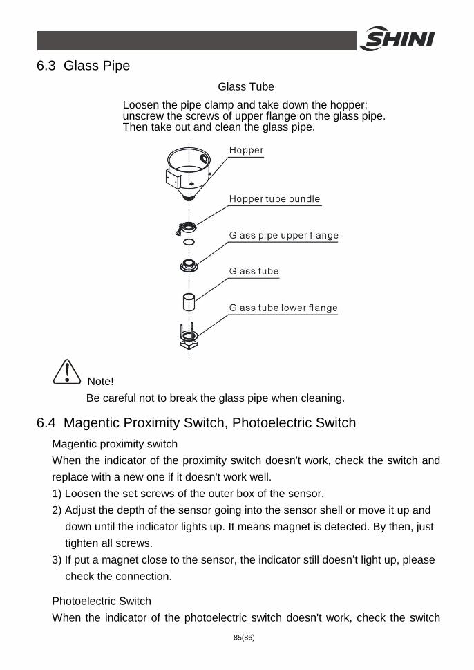
85(86)
6.3 Glass Pipe Glass Tube
Loosen the pipe clamp and take down the hopper; unscrew the screws of upper flange on the glass pipe. Then take out and clean the glass pipe.
Note! Be careful not to break the glass pipe when cleaning.
6.4 Magentic Proximity Switch, Photoelectric Switch Magentic proximity switch When the indicator of the proximity switch doesn't work, check the switch and replace with a new one if it doesn't work well. 1) Loosen the set screws of the outer box of the sensor. 2) Adjust the depth of the sensor going into the sensor shell or move it up and
down until the indicator lights up. It means magnet is detected. By then, just tighten all screws.
3) If put a magnet close to the sensor, the indicator still doesn’t light up, please check the connection.
Photoelectric Switch When the indicator of the photoelectric switch doesn't work, check the switch
86(86)
contact. If it’s in poor contact, please adjust or replace it. 1) Check if it’s in poor contact 2) Please replace a new switch if it’s damaged.
6.5 Maintenance Schedule 6.5.1 About the Machine
Model SN Manufacture date
Voltage Ф V Frequency Hz Power kW
6.5.2 Installation & Inspection
Check if the suction pipe has been correctly connected.
Check if that pipe clips is secured.
Check if mounting base is secured.
Electrical Installation
Voltage: V Hz
Fuse: One-phase: A Three-phase: A
Check power phase.
6.5.3 Daily Checking
Check main power switch. Check filter Check working status of the blower.
6.5.4 Weekly Checking
Check all the electrical cables. Check if there are loose connections of electrical components. Check the screw of the base is secured. Check the air filter.
6.5.5 Monthly Checking
Check the spring lock on the hopper cover is loosed or not. Check the hopper flap is deformed or not. Check the performance of magnetic proximity switch/photoelectrical sensor.
Recommended