Embed Size (px)
Citation preview

SAL-UGP Series Vacuum Powder Loader
Date: Apr, 2013
Version: Ver.B (English)


3(61)
Contents
1. General Description .................................................................................. 7
1.1 Coding Principle ................................................................................... 8
1.2 Feature................................................................................................. 8
1.3 Technical Specifications..................................................................... 10
1.3.1 Technical Specifications (Main Unit)......................................... 10
1.3.2 The Outer Dimension of Hopper............................................... 10
1.3.3 The Installation Dimension of Hopper....................................... 11
1.3.4 Specifications ........................................................................... 12
1.4 Safety Regulations ............................................................................. 14
1.4.1 Safety Signs and Labels ........................................................... 14
1.4.2 Signs and Labels ...................................................................... 14
1.5 Exemption Clause.............................................................................. 14
2. Structure characteristics and working principle .................................. 16
2.1 Main Functions................................................................................... 16
2.1.1 SAL-UGP Working Principle ..................................................... 16
2.2 Assembly Drawing ............................................................................. 18
2.2.1 Assembly Drawing (SAL-1/2HP-UGP)...................................... 18
2.2.2 Parts List (SAL-1HP/2HP-UGP) ............................................... 19
2.2.3 Assembly Drawing (SAL-3.5HP/5HP-UGP).............................. 20
2.2.4 Parts List (SAL-3.5HP/5HP-UGP) ............................................ 21
2.2.5 Assembly Drawing (SAL-7.5HP/10HP-UGP)............................ 22
2.2.6 Parts List (SAL-7.5HP/10HP/15HP-UG)................................... 23
2.2.7 Assembly Drawing of Storage Hopper with Plate Filter ............ 24
2.2.8 Parts List of Storage Hopper with Plate Filter ........................... 25
2.2.9 Assembly Drawing of the Storage Hopper with Bag Filter ........ 26
2.2.10 Parts List of the Storage Hopper with Bag Filter ..................... 27
2.3 Electrical Diagram.............................................................................. 28
2.3.1 Main Circuit (400V)................................................................... 28
2.3.2 Electrical Components Layout (400V) ...................................... 30
2.3.3 Electrical Components List (400V) ........................................... 31
2.3.4 Main Circuit (230V)................................................................... 37

4(61)
2.3.5 Electrical Components Layout (230V) ...................................... 39
2.3.6 Electrical Components List (230V) ........................................... 40
2.4 Description of Electrical Components ................................................ 46
2.4.1 Magnetic Proximity Switch........................................................ 46
2.4.2 Main Electrical Components Description .................................. 46
3. Installation and Debugging..................................................................... 48
3.1 Installation Steps................................................................................ 48
3.1.1 Power Supply ........................................................................... 48
4. Application and Operation...................................................................... 49
4.1 Start / Stop of the Machine................................................................. 49
4.2 Keys on the Control Panel ................................................................. 49
4.3 Parameter Setting .............................................................................. 49
4.3.1 Enter Basic Setting Mode ......................................................... 49
4.3.2 Modify a Parameter .................................................................. 50
4.3.3 Finish Parameter Setting .......................................................... 50
4.3.4 Basic Parameter List ................................................................ 51
4.4 Process Setting.................................................................................. 51
4.4.1 Enter into Process Setting Mode .............................................. 51
4.4.2 Modify a Parameter .................................................................. 52
4.4.3 Finish Parameter Setting .......................................................... 52
4.4.4 Process Parameter List ............................................................ 52
4.5 Special Process Setting ..................................................................... 53
4.5.1 Enter into Special Step Setting Mode ....................................... 53
4.5.2 Modify a Parameter .................................................................. 53
4.5.3 Finish Parameter Setting .......................................................... 54
4.5.4 Parameter List of Special Process Setting................................ 54
4.6 Explanation of Operation Procedures ................................................ 55
4.6.1 Operation Procedures .............................................................. 55
4.6.2 Alarms ...................................................................................... 56
5. Trouble-shooting ..................................................................................... 58
6. Maintenance and Repair ......................................................................... 59
6.1 Material Hopper.................................................................................. 59
6.2 Main Body .......................................................................................... 59

5(61)
6.3 Reed Switch, Photoelectric Switch..................................................... 60
6.4 Weekly Checking ............................................................................... 60
6.5 Monthly Checking............................................................................... 60
6.6 Maintenance Schedule....................................................................... 61
6.6.1 About the Machine.................................................................... 61
6.6.2 Installation & Inspection............................................................ 61
6.6.3 Daily Checking.......................................................................... 61
6.6.4 Weekly Checking...................................................................... 61
6.6.5 Monthly Checking ..................................................................... 61
Table Index
Table 1-1:The Installation Dimension of Hopper ............................................ 12
Table 1-2:Specifications................................................................................. 12
Table 2-1:Parts List (SAL-1HP/2HP-UGP)..................................................... 19
Table 2-2:Parts List (SAL-3.5HP/5HP-UGP).......................................... 21
Table 2-3:Parts List (SAL-7.5HP/10HP-UG) .................................................. 23
Table 2-4:Parts List of Storage Hopper with Plate Filter ................................ 25
Table 2-5:Parts List of the Storage Hopper with Bag Filter ............................ 27
Table 2-6:Electrical Components List (SAL-1HP-UGP) (400V)...................... 31
Table 2-7:Electrical Components List (SAL-2HP-UGP) (400V)...................... 32
Table 2-8:Electrical Components List (SAL-3.5HP-UGP) (400V)................... 33
Table 2-9:Electrical Components List (SAL-5HP-UGP) (400V)...................... 34
Table 2-10:Electrical Components List (SAL-7.5HP-UGP) (400V)................. 35
Table 2-11:Electrical Components List (SAL-10HP-UGP) (400V).................. 36
Table 2-12:Electrical Components List (SAL-1HP-UGP) (230V).................... 40
Table 2-13:Electrical Components List (SAL-2HP-UGP) (230V).................... 41
Table 2-14:Electrical Components List (SAL-3.5HP-UGP) (230V)................. 42
Table 2-15:Electrical Components List (SAL-5HP-UGP) (230V).................... 43
Table 2-16:Electrical Components List (SAL-7.5HP-UGP) (230V)................. 44
Table 2-17:Electrical Components List (SAL-10HP-UGP) (230V).................. 45
Picture Index

6(61)
Picture 1-1:SAL-1HP/2HP-UGP..................................................................... 10
Picture 1-2:SAL-3.5HP/5HP-UGP.................................................................. 10
Picture 1-3:SAL-7.5HP/10HP-UGP................................................................ 10
Picture 1-4:SHR-P-12U.................................................................................. 11
Picture 1-5:SHR-P-30U~SHR-P-90U............................................................. 11
Picture 1-6:SHR-P-30U~SHR-P-90U............................................................. 11
Picture 2-1:SAL-UGP Working Principle ........................................................ 16
Picture 2-2:Assembly Drawing (SAL-1/2HP-UGP)......................................... 18
Picture 2-3:Assembly Drawing (SAL-3.5HP/5HP-UGP) ................................. 20
Picture 2-4:Assembly Drawing (SAL-7.5HP/10HP-UGP) ............................... 22
Picture 2-5:Assembly Drawing of Storage Hopper with Plate Filter................ 24
Picture 2-6:Assembly Drawing of the Storage Hopper with Bag Filter ........... 26
Picture 2-7:Main Circuit 1 (400V) ................................................................... 28
Picture 2-8:Main Circuit 2 (400V) ................................................................... 29
Picture 2-9:Electrical Components Layout (400V).......................................... 30
Picture 2-10:Main Circuit 1 (230V) ................................................................. 37
Picture 2-11:Main Circuit 2 (230V) ................................................................. 38
Picture 2-12:Electrical Components Layout (230V)........................................ 39
Picture 2-13:Magnetic Proximity Switch ......................................................... 46
Picture 2-14:Overload Relay .......................................................................... 46
Picture 4-1:Keys on the Control Panel ........................................................... 49

7(61)
1. General Description
Read this manual carefully before operation to prevent damage of the machine or personal injuries.
SAL-UGP series separate-vacuum hopper loader has all features that come with SAL-UG series product. There is also double-stage blower available as an option. Different model of hopper is available for each individual output capacity needs, especially suitable for 30% and 100% powder loading.
Model: SAL-3.5HP-UGP (Main Unit) Plate Filter + Bag Filter
SHR-P-60U material storage tank+ storage hopper
8(61)
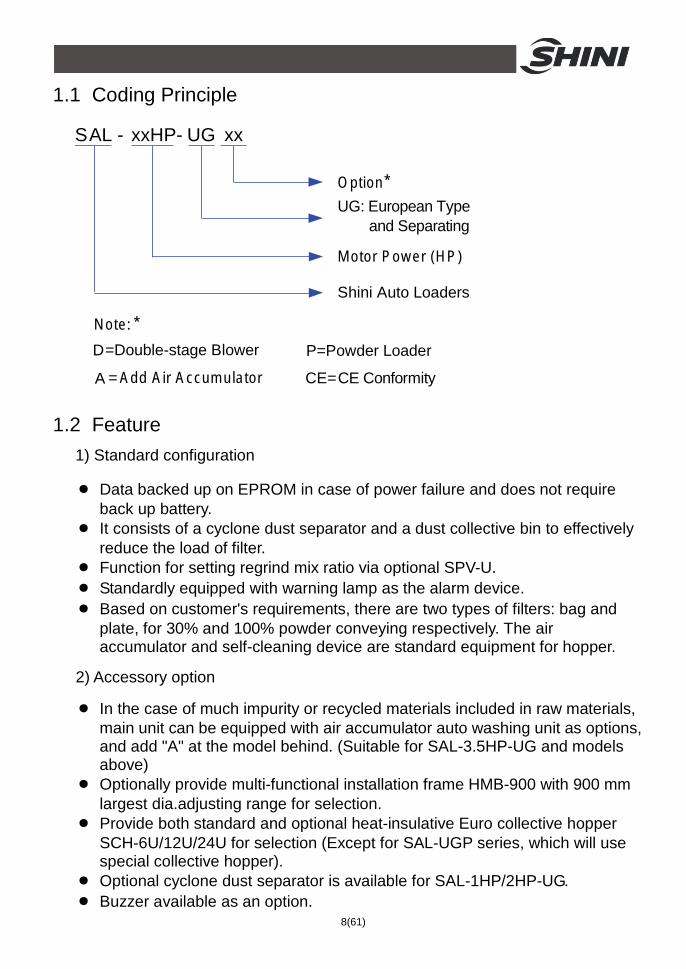
1.1 Coding Principle
SAL - xxHP- UG xx
UG: European Type and Separating
Shini Auto Loaders
Motor Power (HP)
Option*
Note: *
D=Double-stage Blower P=Powder Loader
CE=CE ConformityA = Add Air Accumulator
1.2 Feature 1) Standard configuration
● Data backed up on EPROM in case of power failure and does not require back up battery.
● It consists of a cyclone dust separator and a dust collective bin to effectively reduce the load of filter.
● Function for setting regrind mix ratio via optional SPV-U. ● Standardly equipped with warning lamp as the alarm device. ● Based on customer's requirements, there are two types of filters: bag and
plate, for 30% and 100% powder conveying respectively. The air accumulator and self-cleaning device are standard equipment for hopper.
2) Accessory option
● In the case of much impurity or recycled materials included in raw materials, main unit can be equipped with air accumulator auto washing unit as options, and add "A" at the model behind. (Suitable for SAL-3.5HP-UG and models above)
● Optionally provide multi-functional installation frame HMB-900 with 900 mm largest dia.adjusting range for selection.
● Provide both standard and optional heat-insulative Euro collective hopper SCH-6U/12U/24U for selection (Except for SAL-UGP series, which will use special collective hopper).
● Optional cyclone dust separator is available for SAL-1HP/2HP-UG. ● Buzzer available as an option.

9(61)
● Quick mixing valve can be opted to work with proportional valve to enhance mixing effect.
All service work should be carried out by a person with technical training or corresponding professional experience. The manual contains instructions for both handling and servicing. Chapter 6, which contains service instructions intended for service engineers. Other chapters contain instructions for the daily operator.
Any modifications of the machine must be approved by SHINI in order to avoid personal injury and damage to machine. We shall not be liable for any damage caused by unauthorized change of the machine.
Our company provides excellent after-sales service. Should you have any problem during using the machine, please contact the company or the local vendor.
Headquarter and Taipei factory: Tel: (886) 2 2680 9119 Shini Plastics Technologies (Dongguan), Inc: Tel: (86) 769 8111 6600 Shini Plastics Technologies India Pvt.Ltd.: Tel: (91) 250 3021 166

10(61)
1.3 Technical Specifications 1.3.1 Technical Specifications (Main Unit)
Picture 1-1:SAL-1HP/2HP-UGP
Picture 1-2:SAL-3.5HP/5HP-UGP
Picture 1-3:SAL-7.5HP/10HP-UGP 1.3.2 The Outer Dimension of Hopper

11(61)
Picture 1-4:SHR-P-12U
Picture 1-5:SHR-P-30U~SHR-P-90U 1.3.3 The Installation Dimension of Hopper
Picture 1-6:SHR-P-30U~SHR-P-90U

12(61)
Table 1-1:The Installation Dimension of Hopper
Model D1(mm) D2(mm) D3(mm) D4(mm) D5(mm)
SHR-P-12U Ф197 Ф254.5 Ф275 Ф231.5 Ф9
SHR-P-30U Ф377 Ф413 Ф430 - Ф7
SHR-P-30U-1 Ф377 Ф413 Ф430 - Ф7
SHR-P-30U-2 Ф377 Ф413 Ф430 - Ф7
SHR-P-60U Ф437 Ф470 Ф490 - Ф7
SHR-P-60U-3 Ф437 Ф470 Ф490 - Ф7
SHR-P-90U Ф547 Ф583 Ф600 - Ф7
SHR-P-90U-5 Ф547 Ф583 Ф600 - Ф7
1.3.4 Specifications
Table 1-2:Specifications
For Conveying Raw Material Contains 30% Powder (BAG FILTERS are fitted to the powder receiver)
Main Unit Powder Receiver Dimensions (mm)
Model
Motor
Power
(kW)
(50/60Hz)
Specifi-
cation Applied to
Conveying
Pipe Dia.
Air
Suction
Pipe
Dia.
Hopper
Capacity
(L)
Hopper
Dia.
(mm)
Conveying
Capacity
(kg / hr)
Filter
Cloth
Quantity (Main Unit)
H×W×D
(Receiver)
H×W×D
SAL-1HP-UGP 0.75 /
0.85 SHR-P-12U 12L Φ270 300 3 940×535×380
SAL-2HP-UGP 1.5 / 1.8 SHR-P-30U
1.5” 1.5”
30L Φ380 400 7
1000×400×500
1325×730×470
SAL-3.5HP-UGP 2.4 / 2.6 800
SAL-5HP-UGP 1380×490×590
SAL-5HP-UGP-D 3.7 / 4.2
SHR-P-60U 2” 2” 60L Φ440 1200
10
1380×690×590
1500×780×500
SAL-7.5HP-UGP 1830×585×675
SAL-7.5HP-UGP-D 5.5 / 6.3 1500
1830×740×675
SAL-10HP-UGP 1830×585×675
SAL-10HP-UGP-D 7.5 / 8.6
3Φ
SHR-P-90U 2.5” 2.5” 90L Φ550
2000
19
1830×740×675
1640×890×635
13(61)
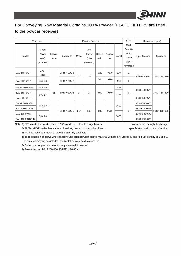
For Conveying Raw Material Contains 100% Powder (PLATE FILTERS are fitted to the powder receiver)
Main Unit Powder Receiver Dimensions (mm)
Model
Motor
Power
(kW)
(50/60Hz)
Specifi-
cation Applied to Model
Motor
Power
(kW)
(50/60Hz)
Specifi-
cation
Applied
to Model
Filter
Cloth
Quantity
Motor
Power
(kW)
(50/60Hz)
Specifi-cation Applied to
SAL-1HP-UGP 0.75 /
0.85 SHR-P-30U-1 12L Φ270 300 1
SAL-2HP-UGP 1.5 / 1.8 SHR-P-30U-2
1.5” 1.5” 30L Φ380
400 2
1000×400×500 1325×730×470
SAL-3.5HP-UGP 2.4 / 2.6 800
SAL-5HP-UGP 1380×490×570
SAL-5HP-UGP-D 3.7 / 4.2
SHR-P-60U-3 2” 2” 60L Φ440 1200
3
1380×690×570
1500×780×500
SAL-7.5HP-UGP 1830×585×675
SAL-7.5HP-UGP-D 5.5 / 6.3 1500
1830×740×675
SAL-10HP-UGP 1830×585×675
SAL-10HP-UGP-D 7.5 / 8.6
3Φ
SHR-P-90U-5 2.5” 2.5” 90L Φ550
2000
5
1830×740×675
1640×890×635
Note: 1) "P" stands for powder loader, "D" stands for double stage blower. We reserve the right to change 2) All SAL-UGP series has vacuum breaking valve to protect the blower. specifications without prior notice. 3) PU heat-resistant material pipe is optionally available. 4) Test condition of conveying capacity: Use dried powder plastic material without any viscosity and its bulk density is 0.6kg/L, vertical conveying height: 4m, horizontal conveying distance: 5m. 5) Collective hopper can be optionally selected if needed. 6) Power supply: 3Ф, 230/400/460/575V, 50/60Hz.

14(61)
1.4 Safety Regulations Strictly abide by the following safety regulations to prevent damage of the machine or personal injuries.
1.4.1 Safety Signs and Labels
All the electrical components should be installed by professional technicians. Turn off the main switch and control switch during maintenance or repair.
Warning! High voltage! This sign is attached on the cover of control box!
Warning! Be careful! Be more careful at the place where this sign appears!
Attention! No need for regular inspection because all the electrical parts in the control unit are fixed tightly!
1.4.2 Signs and Labels
1. Please clean the suction filter regularly to avoid clogging and ensure proper loading capacity and long life span.
2. The one year warranty does not cover the suction filter, please clean the filter carefully.
1.5 Exemption Clause The following statements clarify the responsibilities and regulations born by any buyer or user who purchases products and accessories from Shini (including employees and agents). Shini is exempted from liability for any costs, fees, claims and losses caused by reasons below:
1. Any careless or man-made installations, operation and maintenances upon machines without referring to the Manual prior to machine using.

15(61)
2. Any incidents beyond human reasonable controls, which include man-made vicious or deliberate damages or abnormal power, and machine faults caused by irresistible natural disasters including fire, flood, storm and earthquake.
3. Any operational actions that are not authorized by Shini upon machine, including adding or replacing accessories, dismantling, delivering or repairing.
4. Employing consumables or oil media that are not appointed by Shini.

16(61)
2. Structure characteristics and working principle 2.1 Main Functions
SAL-UGP "Euro" separate-vacuum hopper loader are applicable to convey the mixture of plastic granule and powder or all powders. It makes good use of motor generated vacuum to form a pressure gap within hopper, by which means to convey.
2.1.1 SAL-UGP Working Principle
Names of Parts:
1. Air suction pipe (blower use) 2. Blower 3. Vacuum breaking diaphragm valve 4. Steel wired plastic pipe 5. Dust collective barrel 6. Air suction pipe (hopper use) 7. Filter 1 8. Filtering barrel 9. Red alarm light 10. Main power switch 11. Electrical control box 12. Manual controller 13. Material inlet pipe 14. Hopper 15. Crew material 16. Non-return flap 17. Magnetic proximity switch 18. Wiring box 19. Diaphragm valve 20. Storage tank 21. Filter 2
Picture 2-1:SAL-UGP Working Principle After starting the machine, blower (2) begins to work to produce high-pressure vacuum inside of material hopper (15), meanwhile close the reverse stopping flap (17). Materials will be drawn into material hopper by pressure difference through material inlet (13). When material suction is completed, motor stops

17(61)
working, and the materials automatically fall down by self-gravity. Motor will be delayed when magnetic proximity switch (18) detects no materials left in the hopper. And then, open the diaphragm valve (19), the high-pressure air in the storage tank (20) will pass the washing device to clean the dust covered in the filter 1 (21) and hopper (14), then the motor starts again. If the machine cannot suck materials for three times, the red alarm light (9) on control box (11) will blink.
When the blower (2) sucks materials, the air inside the air-inputting pipe will past filter 2 (7) for filtering. Few dust sticks to the filter. After the blower finishes the suction, the vacuum breaking diaphragm valve (3) installed between the blower and filter will create a reverse impulsive airflow to shake down the dust sticking to the filter to the dust collection bucket (5).

18(61)
2.2 Assembly Drawing 2.2.1 Assembly Drawing (SAL-1/2HP-UGP)
Remarks: Please refer to material list 2.2.2 for specific explanation of the Arabic numbers
in parts drawing.
Picture 2-2:Assembly Drawing (SAL-1/2HP-UGP)

19(61)
2.2.2 Parts List (SAL-1HP/2HP-UGP)
Table 2-1:Parts List (SAL-1HP/2HP-UGP)
No. Name Part No. No. Name Part No.
1 Anti-vibration pad YW03005000000 15 Filter barrel lid assembly
-
2 Base BL26000202420 16 Controller holder BL26010241820
3 Lower welding block on column
- 17 Main switch * YE10200300000
4 Standing post BL26000202920 18 Control box BL21000101920
5 Upper welding block on column
- 19 Alarm light YE83305100200
6 Blower flange - 20 Filter barrel lid barrel YR10030000000
7 Air inlet pipe BL21000200320 21 Filter barrel lid -
8 Diaphragm valve connection pipe
- 22 Air filter* YR50708000000
9 Vacuum breaking diaphragm valve
BY20015000050 23 Star nut YW09051600000
High pressure pipe 1HP BM30031000150 24 Filter container seal ring*
YR10708000100 10
High pressure pipe 2HP BM30042000050 25 Spring clip* YW02003000400
11 Clip YW02000200000 26 Acryl BH32070000050
12 Steel wired plastic pipe YR60157000000 27 Seal ring YR40000400000
13 Filter fixing bracket - 28 Iron sheet of 4-hole sight glass
YW09000000400
14 Filter barrel base fastener
- 29 Filter barrel BL26000203621
* means possible broken parts. ** means easy broken part. and spare backup is suggested. Please confirm the version of manual before placing the purchase order to guarantee that the item number of the spare part is in accordance with the real object.

20(61)
2.2.3 Assembly Drawing (SAL-3.5HP/5HP-UGP)
Remarks: Please refer to material list 2.2.4 for specific explanation of the Arabic numbers
in parts drawing.
Picture 2-3:Assembly Drawing (SAL-3.5HP/5HP-UGP)

21(61)
2.2.4 Parts List (SAL-3.5HP/5HP-UGP)
Table 2-2:Parts List (SAL-3.5HP/5HP-UGP)
No. Name Part No. No. Name Part No. 1 Anti-vibration pad Ф50 YW03005000000 21 Filter barrel roll BL19003500120 2 Flat washer 8 YW66082200100 22 Filter barrel assembly -
3 Nut M12 YW64012100000 23 6-hole acryl YR40001200000
4 Base BL21003500120 24 6-hole sight glass fastene
YR40000600000
5 Air inlet pipe BL26003506520- 25 Iron sheet of 6-hole sight glass
YW09000600000
6 Blower flange - 26 Butterfly nut 5/16″ YW09051600000
7 Vacuum breaking diaphragm valve 1.5″
BY20015000050 27 Flat washer YW66082200100
8 Vacuum breaking diaphragm valve piping
BL21003500420 28 Strainer fixing plate 8 BL21003500520
9 Lower welded block of stand column
- 29 Air filter ADC2 YR50181100000
10 Right stand column BL26003506620 30 Air suction pipe -
11 Upper welded block of stand column
- 31 Coupling clip YW07000200000
12 Snap hook* YW02003000400 32 Filter barrel lid assembly - High pressure blower 3.5HP
BM30053500050 33 Alarm light YE83305100200
High pressure blower 5HP
BM30055000050 34 Control base board - 13
High pressure blower 5HP (two-stage)
YM30433700000 35 Cover board -
14 Dust collection bin BL26003507021 36 Main power switch YE10210300000
15 4-hole acryl BH32070000050 37 Controller holder BL26010241820
16 4-hole sight glass fastener
YR40000400000 38 Control box BL26003505321
17 Iron sheet of 4-hole sight glass
YW09000000400 39 Line jig fixing plate Insulation material
-
18 Pipe bundle 2.5″ YW02002500000 40 Filter barrel support -
19 Steel wired plastic Pipe 2”
YR60205000100 41 Control cabinet mounting plate
-
20 Dust collecting barrel fastener*
YR10708000100 42 Left stand column BL26003506620
* means possible broken parts. ** means easy broken part. and spare backup is suggested. Please confirm the version of manual before placing the purchase order to guarantee that the item number of the spare part is in accordance with the real object.

22(61)
2.2.5 Assembly Drawing (SAL-7.5HP/10HP-UGP)
Remarks: Please refer to material list 2.2.6 for specific explanation of the Arabic numbers
in parts drawing.
Picture 2-4:Assembly Drawing (SAL-7.5HP/10HP-UGP)

23(61)
2.2.6 Parts List (SAL-7.5HP/10HP/15HP-UG)
Table 2-3:Parts List (SAL-7.5HP/10HP-UG)
No. Name Part No. No. Name Part No. 1 Hex. head screw YW60084000200 20 Clip YW02002500000 2 Spring washer YW66081600000 21 Steel wire hose YR60002500000
3” movable castor YW03000300200 22 Filter barrel assembly - 3
3” castor with brake YW03000300000 23 Butterfly nut YW69051600000
4 Base BL26007502721 24 Filter fixing plate BL26007504720 High pressure blower 7.5HP
BM30075000050 25 Air filter* YR50221400000
High pressure blower 7.5HP single-stage
YM30635500000 26 Spring clip* YW02003000400
High pressure blower 10HP
BM30081000050 27 Filter barrel lid assembly - 5
High pressure blower 10HP single-stage
YM30637500000 28 2.5” coupling clip YW07002500600
6 Blower flange - 29 Filter barrel lid assembly -
7 Air inlet fastener BL26007504920 30 Alarm light YE83305100200
8 Pneumatic diaphragm valve
BY20020000150 31 Main switch YE10210300000
9 Pneumatic valve coupling
BL26007502020 32 Controller holder BL26010241820
10 Castor YW03002500000 33 Control cabinet BL26007503521
11 Dust collecting barrel BL26007502421 34 Control cabinet mounting plate
-
12 Aluminium handle BW20012000040 35 Iron sheet of 4-hole sight glass
YW09000000400
13 Dust collecting barrel seal ring*
- 36 Acryl BH32070000050
14 Large handle YW02003000100 37 4-holes window seal ring
YR40000400000
15 Cyclone baffle - 38 Middle board -
16 Bottom ring of filter barrel
- 39 Supporting frame 1 -
17 6-holes window seal ring
YR40000600000 40 Pillar of filter barrel -
18 Acryl YR40001200000 41 Filter fixing bracket -
19 Iron sheet of 6-hole sight glass
YW09000600000
* means possible broken parts. ** means easy broken part. and spare backup is suggested. Please confirm the version of manual before placing the purchase order to guarantee that the item number of the spare part is in accordance with the real object.

24(61)
2.2.7 Assembly Drawing of Storage Hopper with Plate Filter
Remarks: Please refer to material list 2.2.8 for specific explanation of the Arabic numbers in
parts drawing.
Picture 2-5:Assembly Drawing of Storage Hopper with Plate Filter

25(61)
2.2.8 Parts List of Storage Hopper with Plate Filter
Table 2-4:Parts List of Storage Hopper with Plate Filter
No. Name Part No. No. Name Part No.
1 Fastener for filtering barrel YR10010000200 21 Filter cloth YP82050000000
2 Cruciform slot screw YW63063000000 22 Filter barrel body -
3 Magnet cover BL21000600120 23 Fixing plate of suction pipe -
4 Permanent magnet YW90213700000 24 Fastener of the suction pipe -
5 Magnet cover BH12000600010 25 Suction pipe -
6 Press block - 26 Non-return flap BL27002400920
7 Flat washer YR40000400000 27 Non-return valve -
8 Lockup nut YW64000600200 28 Mounting bracket YE30004200000
9 Connecting block for discharging plate
BL27006000020 29 Pressure regulating valves
YE30421400000
10 Discharging plate BL27006001120 30 Cruciform slot screw YW63064000000
11 The cover of sensor - 31 Plate filter YR50450500000
12 Control box - 32 Flange for the filter -
13 Ball valve 3/8” YW50030800100 33 Square aluminum handle
BW20012000040
14 Air accumulator BL27006000120 34 Filter barrel lid fastener -
15 Fixing flange of the air accumulator
- 35 Big handle in new design
-
16 Air pipe coupling YW80161200000 36 Diaphragm valve YE30020000100
17 Air pipe YR60161000000 37 Filter barrel lid -
18 Copper connector - 38 vacuum separating valve
BY20500000050
19 Spring clip** YW02003000400 39 Air suction port coupling BL27006001620
20 Air vent window BL27006001320 * means possible broken parts. ** means easy broken part. and spare backup is suggested. Please confirm the version of manual before placing the purchase order to guarantee that the item number of the spare part is in accordance with the real object.

26(61)
2.2.9 Assembly Drawing of the Storage Hopper with Bag Filter
Remarks: Please refer to material list 2.2.10 for specific explanation of the Arabic numbers
in parts drawing.
Picture 2-6:Assembly Drawing of the Storage Hopper with Bag Filter

27(61)
2.2.10 Parts List of the Storage Hopper with Bag Filter
Table 2-5:Parts List of the Storage Hopper with Bag Filter
No. Name Part No. No. Name Part No.
1 Fastener for filtering barrel YR10010000200 21 Filter cloth YP82050000000
2 Cruciform slot screw YW63063000000 22 Filter barrel body -
3 Magnet cover BL21000600120 23 Fixing plate of suction pipe -
4 Permanent magnet YW90213700000 24 Fastener of the suction pipe -
5 Magnet cover BH12000600010 25 Suction pipe -
6 Press block - 26 Non-return flap BL27002400920
7 Flat washer YR40000400000 27 Non-return valve -
8 Lockup nut YW64000600200 28 Mounting bracket YE30004200000
9 Connecting block for discharging plate
BL27006000020 29 Pressure regulating valves YE30421400000
10 Discharging plate BL27006001120 30 Cruciform slot screw YW63064000000
11 The cover of sensor - 31 Filtering bag SHR-P-30U-90U / SHR-P-12U
BP82774800044 BP82774000044
12 Control box - 32 Flange for the filter -
13 Ball valve 3/8” YW50030800100 33 Square aluminum handle BW20012000040
14 Air accumulator BL27006000120 34 Filter barrel lid fastener -
15 Fixing flange of the air accumulator
- 35 Big handle in new design -
16 Air pipe coupling YW80161200000 36 Diaphragm valve YE30020000100
17 Air pipe YR60161000000 37 Filter barrel lid -
18 Copper connector - 38 vacuum separating valve BY20500000050
19 Spring clip** YW02003000400 39 Air suction port coupling BL27006001620
20 Air vent window BL27006001320 * means possible broken parts. ** means easy broken part. and spare backup is suggested. Please confirm the version of manual before placing the purchase order to guarantee that the item number of the spare part is in accordance with the real object.

28(61)
2.3 Electrical Diagram 2.3.1 Main Circuit (400V)
Picture 2-7:Main Circuit 1 (400V)

29(61)
Picture 2-8:Main Circuit 2 (400V)

30(61)
2.3.2 Electrical Components Layout (400V)
Picture 2-9:Electrical Components Layout (400V)

31(61)
2.3.3 Electrical Components List (400V)
Table 2-6:Electrical Components List (SAL-1HP-UGP) (400V)
SAL-1HP-UGP NO. Symbol Name
Specification Part NO. 1 Q1 Main switch* 16A YE10200300000 2 Q2 Circuit breakers* 15A YE40601500000
3 K1 Contactors** 230V 50/60Hz YE00300000000
4 T Transformer** 350mA YE70350400000
5 F1 Overload relays 2~3.2A YE01023200000
6 F2 Fuse box** 500V 32A YE41032200000
7 - Fuse** 500V 2A 10×38 YE46002000100
8 F3 Fuse box** 250V 2A YE41001000000
9 S1 Control switch 4P (WH) YE10210400000
10 H1 Buzzer 60-250VAC 50/60Hz YE84003500000
11 H2 Alarm lamp 230VAC 50/60Hz YE83305100200
12 A1 Microomputer mainboard**
230VAC 50/60Hz -
13 A2 Keypad** - -
14 X1 Heavy duty connectors
16A 400V YE68061640100
15 X2 Terminal board 2.5mm2 YE61250040000
16 - Terminal board 2.5mm2 PE YE61253500000
17 - Terminal board 2.5mm2 YE61250040000
18 - Terminal board 2.5mm2 PE YE61253500000
19 X3 Waterproof linker 250V 3P YE62163000100
20 M Blower** 1HP -
21 Y1 Solenoid vavle* 230V 50/60Hz YE32051800300
22 Y2 Solenoid vavle* 230V 50/60Hz YE32212000000 * means possible broken parts. ** means easy broken part. and spare backup is suggested. Please confirm the version of manual before placing the purchase order to guarantee that the item number of the spare part is in accordance with the real object.

32(61)
Table 2-7:Electrical Components List (SAL-2HP-UGP) (400V)
SAL-2HP-UGP NO. Symbol Name
Specification Part NO. 1 Q1 Main switch* 16A YE10200300000
2 Q2 Circuit breakers* 15A YE40601500000
3 K1 Contactors** 230V 50/60Hz YE00300000000
4 T Transformer** 350mA YE70350400000
5 F1 Overload relays 3.2~5A YE01032500000
6 F2 Fuse box** 500V 32A YE41032200000
7 - Fuse** 500V 2A 10×38 YE46002000100
8 F3 Fuse box** 250V 2A YE41001000000
9 S1 Control switch 4P (WH) YE10210400000
10 H1 Buzzer 60-250VAC 50/60Hz YE84003500000
11 H2 Alarm lamp 230VAC 50/60Hz YE83305100200
12 A1 Microomputer mainboard**
230VAC 50/60Hz -
13 A2 Keypad** - -
14 X1 Heavy duty connectors
16A 400V YE68061640100
15 X2 Terminal board 2.5mm2 YE61250040000
16 - Terminal board 2.5mm2 PE YE61253500000
17 - Terminal board 2.5mm2 YE61250040000
18 - Terminal board 2.5mm2 PE YE61253500000
19 X3 Waterproof linker 250V 3P YE62163000100
20 M Blower** 2HP -
21 Y1 Solenoid vavle* 230V 50/60Hz YE32051800300
22 Y2 Solenoid vavle* 230V 50/60Hz YE32212000000 * means possible broken parts. ** means easy broken part. and spare backup is suggested. Please confirm the version of manual before placing the purchase order to guarantee that the item number of the spare part is in accordance with the real object.

33(61)
Table 2-8:Electrical Components List (SAL-3.5HP-UGP) (400V)
SAL-3.5HP-UGP NO. Symbol Name
Specification Part NO. 1 Q1 Main switch* 16A YE10200300000
2 Q2 Circuit breakers* 20A YE40602000000
3 K1 Contactors** 230V 50/60Hz YE00310000000
4 T Transformer** 350mA YE70350400000
5 F1 Overload relays 5~8A YE01050800000
6 F2 Fuse box** 500V 32A YE41032200000
7 - Fuse** 500V 2A 10×38 YE46002000100
8 F3 Fuse box** 250V 2A YE41001000000
9 S1 Control switch 4P (WH) YE10210400000
10 H1 Buzzer 60-250VAC 50/60Hz YE84003500000
11 H2 Alarm lamp 230VAC 50/60Hz YE83305100200
12 A1 Microomputer mainboard**
230VAC 50/60Hz -
13 A2 Keypad** - -
14 X1 Heavy duty connectors
16A 400V YE68061640100
15 X2 Terminal board 2.5mm2 YE61250040000
16 - Terminal board 2.5mm2 PE YE61253500000
17 - Terminal board 2.5mm2 YE61250040000
18 - Terminal board 2.5mm2 PE YE61253500000
19 X3 Waterproof linker 250V 3P YE62163000100
20 M Blower** 3.5HP -
21 Y1 Solenoid vavle* 230V 50/60Hz YE32051800300
22 Y2 Solenoid vavle* 230V 50/60Hz YE32212000000 * means possible broken parts. ** means easy broken part. and spare backup is suggested. Please confirm the version of manual before placing the purchase order to guarantee that the item number of the spare part is in accordance with the real object.

34(61)
Table 2-9:Electrical Components List (SAL-5HP-UGP) (400V)
SAL-5HP-UGP NO. Symbol Name
Specification Part NO. 1 Q1 Main switch* 16A YE10200300000
2 Q2 Circuit breakers* 25A YE40602500000
3 K1 Contactors** 230V 50/60Hz YE00310000000
4 T Transformer** 350mA YE70350400000
5 F1 Overload relays 6.3~10A YE01631000000
6 F2 Fuse box** 500V 32A YE41032200000
7 - Fuse** 500V 2A 10×38 YE46002000100
8 F3 Fuse box** 250V 2A YE41001000000
9 S1 Control switch 4P (WH) YE10210400000
10 H1 Buzzer 60-250VAC 50/60Hz YE84003500000
11 H2 Alarm lamp 230VAC 50/60Hz YE83305100200
12 A1 Microomputer mainboard**
230VAC 50/60Hz -
13 A2 Keypad** - -
14 X1 Heavy duty connectors
16A 400V YE68061640100
15 X2 Terminal board 2.5mm2 YE61250040000
16 - Terminal board 2.5mm2 PE YE61253500000
17 - Terminal board 2.5mm2 YE61250040000
18 - Terminal board 2.5mm2 PE YE61253500000
19 X3 Waterproof linker 250V 3P YE62163000100
20 M Blower** 5HP -
21 Y1 Solenoid vavle* 230V 50/60Hz YE32051800300
22 Y2 Solenoid vavle* 230V 50/60Hz YE32212000000 * means possible broken parts. ** means easy broken part. and spare backup is suggested. Please confirm the version of manual before placing the purchase order to guarantee that the item number of the spare part is in accordance with the real object.

35(61)
Table 2-10:Electrical Components List (SAL-7.5HP-UGP) (400V)
SAL-7.5HP-UGP NO. Symbol Name
Specification Part NO. 1 Q1 Main switch* 25A YE10210300000
2 Q2 Circuit breakers* 40A YE40604000000
3 K1 Contactors** 230V 50/60Hz YE00320000000
4 T Transformer** 350mA YE70350400000
5 F1 Overload relays 10~16A YE01101600100
6 F2 Fuse box** 500V 32A YE41032200000
7 - Fuse** 500V 2A 10×38 YE46002000100
8 F3 Fuse box** 250V 2A YE41001000000
9 S1 Control switch 4P (WH) YE10210400000
10 H1 Buzzer 60-250VAC 50/60Hz YE84003500000
11 H2 Alarm lamp 230VAC 50/60Hz YE83305100200
12 A1 Microomputer mainboard**
230VAC 50/60Hz -
13 A2 Keypad** - -
14 X1 Heavy duty connectors
16A 400V YE68061640100
15 X2 Terminal board 2.5mm2 YE61250040000
16 - Terminal board 2.5mm2 PE YE61253500000
17 - Terminal board 2.5mm2 YE61250040000
18 - Terminal board 2.5mm2 PE YE61253500000
19 X3 Waterproof linker 250V 3P YE62163000100
20 M Blower** 7.5HP -
21 Y1 Solenoid vavle* 230V 50/60Hz YE32051800300
22 Y2 Solenoid vavle* 230V 50/60Hz YE32212000000 * means possible broken parts. ** means easy broken part. and spare backup is suggested. Please confirm the version of manual before placing the purchase order to guarantee that the item number of the spare part is in accordance with the real object.

36(61)
Table 2-11:Electrical Components List (SAL-10HP-UGP) (400V)
SAL-10HP-UGP NO. Symbol Name
Specification Part NO. 1 Q1 Main switch* 32A YE10220300000
2 Q2 Circuit breakers* 50A YE40605000000
3 K1 Contactors** 230V 50/60Hz YE00330000000
4 T Transformer** 350mA YE70350400000
5 F1 Overload relays 12.5~20A YE01125200100
6 F2 Fuse box** 500V 32A YE41032200000
7 - Fuse** 500V 2A 10×38 YE46002000100
8 F3 Fuse box** 250V 2A YE41001000000
9 S1 Control switch 4P (WH) YE10210400000
10 H1 Buzzer 60-250VAC 50/60Hz YE84003500000
11 H2 Alarm lamp 230VAC 50/60Hz YE83305100200
12 A1 Microomputer mainboard**
230VAC 50/60Hz -
13 A2 Keypad** - -
14 X1 Heavy duty connectors
16A 400V YE68061640100
15 X2 Terminal board 2.5mm2 YE61250040000
16 - Terminal board 2.5mm2 PE YE61253500000
17 - Terminal board 2.5mm2 YE61250040000
18 - Terminal board 2.5mm2 PE YE61253500000
19 X3 Waterproof linker 250V 3P YE62163000100
20 M Blower** 10HP -
21 Y1 Solenoid vavle* 230V 50/60Hz YE32051800300
22 Y2 Solenoid vavle* 230V 50/60Hz YE32212000000 * means possible broken parts. ** means easy broken part. and spare backup is suggested. Please confirm the version of manual before placing the purchase order to guarantee that the item number of the spare part is in accordance with the real object.
37(61)
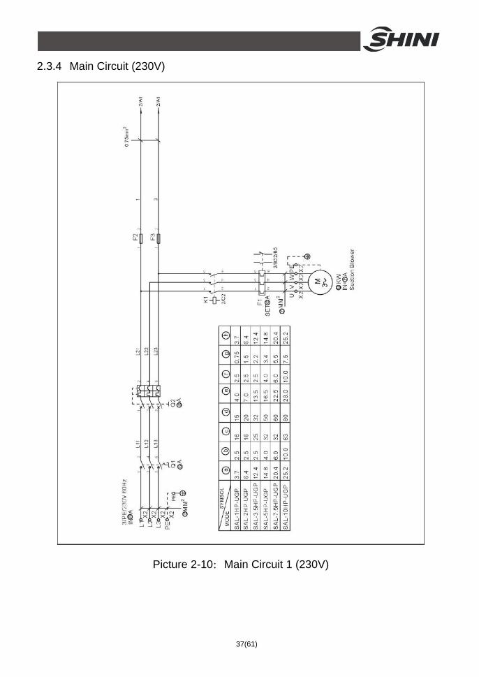
2.3.4 Main Circuit (230V)
Picture 2-10:Main Circuit 1 (230V)

38(61)
Picture 2-11:Main Circuit 2 (230V)
39(61)
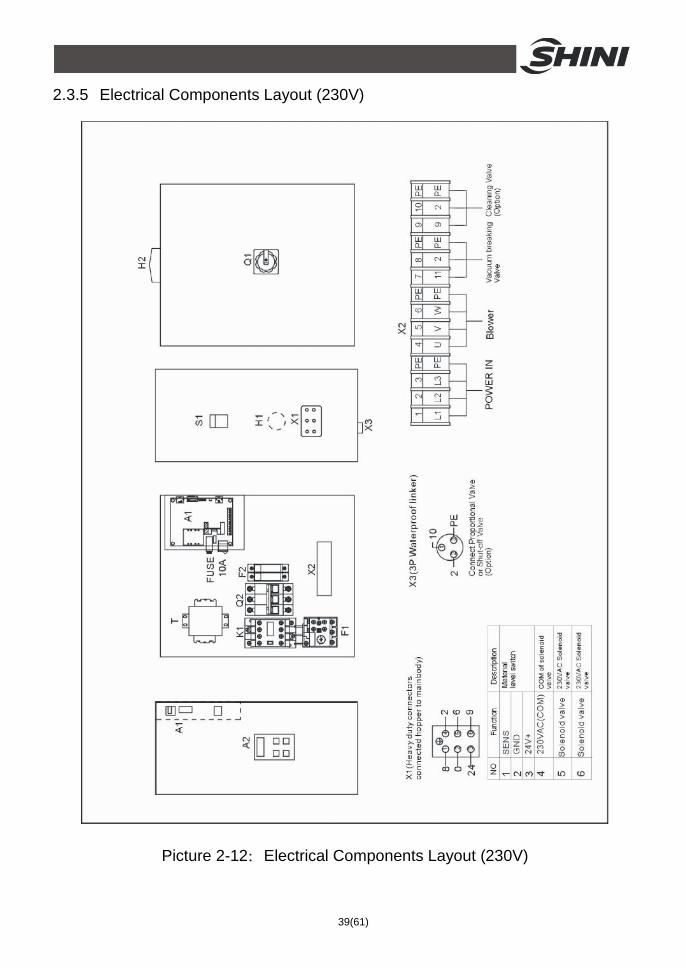
2.3.5 Electrical Components Layout (230V)
Picture 2-12:Electrical Components Layout (230V)

40(61)
2.3.6 Electrical Components List (230V)
Table 2-12:Electrical Components List (SAL-1HP-UGP) (230V)
SAL-1HP-UGP NO. Symbol Name
Specification Part NO. 1 Q1 Main switch* 16A YE10200300000 2 Q2 Circuit breakers* 15A YE40601500000
3 K1 Contactors** 230V 50/60Hz YE00300000000
4 F1 Overload relays 3.2~5A YE01032500000
5 F2 F3 Fuse** 250V 2A YE41001000000
6 S1 Control switch 4P (WH) YE10210400000
7 H1 Buzzer 60-250VAC 50/60Hz YE84003500000
8 H2 Alarm lamp 230VAC 50/60Hz YE83305100200
9 A1 Microomputer mainboard**
230VAC 50/60Hz -
10 A2 Keypad** - -
11 X1 Heavy duty connectors
16A 400V YE68061640100
12 X2 Terminal board 2.5mm2 YE61250040000
13 - Terminal board 2.5mm2 PE YE61253500000
14 - Terminal board 2.5mm2 YE61250040000
15 - Terminal board 2.5mm2 PE YE61253500000
16 X3 Waterproof linker 250V 3P YE62163000100
17 M Blower** 1HP -
18 Y1 Solenoid vavle* 230V 50/60Hz YE32051800300
19 Y2 Solenoid vavle* 230V 50/60Hz YE32212000000 * means possible broken parts. ** means easy broken part. and spare backup is suggested. Please confirm the version of manual before placing the purchase order to guarantee that the item number of the spare part is in accordance with the real object.

41(61)
Table 2-13:Electrical Components List (SAL-2HP-UGP) (230V)
SAL-2HP-UGP NO. Symbol Name
Specification Part NO. 1 Q1 Main switch* 16A YE10200300000
2 Q2 Circuit breakers* 20A YE40602000000
3 K1 Contactors** 230V 50/60Hz YE00310000000
4 F1 Overload relays 5~8A YE01050800000
5 F2 F3 Fuse** 250V 2A YE41001000000
6 S1 Control switch 4P (WH) YE10210400000
7 H1 Buzzer 60-250VAC 50/60Hz YE84003500000
8 H2 Alarm lamp 230VAC 50/60Hz YE83305100200
9 A1 Microomputer mainboard**
230VAC 50/60Hz -
10 A2 Keypad** - -
11 X1 Heavy duty connectors
16A 400V YE68061640100
12 X2 Terminal board 2.5mm2 YE61250040000
13 - Terminal board 2.5mm2 PE YE61253500000
14 - Terminal board 2.5mm2 YE61250040000
15 - Terminal board 2.5mm2 PE YE61253500000
16 X3 Waterproof linker 250V 3P YE62163000100
17 M Blower** 2HP -
18 Y1 Solenoid vavle* 230V 50/60Hz YE32051800300
19 Y2 Solenoid vavle* 230V 50/60Hz YE32212000000 * means possible broken parts. ** means easy broken part. and spare backup is suggested. Please confirm the version of manual before placing the purchase order to guarantee that the item number of the spare part is in accordance with the real object.

42(61)
Table 2-14:Electrical Components List (SAL-3.5HP-UGP) (230V)
SAL-3.5HP-UGP NO. Symbol Name
Specification Part NO. 1 Q1 Main switch* 25A YE10210300000
2 Q2 Circuit breakers* 32A YE40603200000
3 K1 Contactors** 230V 50/60Hz YE00320000000
4 F1 Overload relays 8~12.5A YE01812500100
5 F2 F3 Fuse** 250V 2A YE41001000000
6 S1 Control switch 4P (WH) YE10210400000
7 H1 Buzzer 60-250VAC 50/60Hz YE84003500000
8 H2 Alarm lamp 230VAC 50/60Hz YE83305100200
9 A1 Microomputer mainboard**
230VAC 50/60Hz -
10 A2 Keypad** - -
11 X1 Heavy duty connectors
16A 400V YE68061640100
12 X2 Terminal board 2.5mm2 YE61250040000
13 - Terminal board 2.5mm2 PE YE61253500000
14 - Terminal board 2.5mm2 YE61250040000
15 - Terminal board 2.5mm2 PE YE61253500000
16 X3 Waterproof linker 250V 3P YE62163000100
17 M Blower** 3.5HP -
18 Y1 Solenoid vavle* 230V 50/60Hz YE32051800300
19 Y2 Solenoid vavle* 230V 50/60Hz YE32212000000 * means possible broken parts. ** means easy broken part. and spare backup is suggested. Please confirm the version of manual before placing the purchase order to guarantee that the item number of the spare part is in accordance with the real object.

43(61)
Table 2-15:Electrical Components List (SAL-5HP-UGP) (230V)
SAL-5HP-UGP NO. Symbol Name
Specification Part NO. 1 Q1 Main switch* 32A YE10220300000
2 Q2 Circuit breakers* 50A YE40605000000
3 K1 Contactors** 230V 50/60Hz YE00330000000
4 F1 Overload relays 12.5~20A YE01125200100
5 F2 F3 Fuse** 250V 2A YE41001000000
6 S1 Control switch 4P (WH) YE10210400000
7 H1 Buzzer 60-250VAC 50/60Hz YE84003500000
8 H2 Alarm lamp 230VAC 50/60Hz YE83305100200
9 A1 Microomputer mainboard**
230VAC 50/60Hz -
10 A2 Keypad** - -
11 X1 Heavy duty connectors
16A 400V YE68061640100
12 X2 Terminal board 2.5mm2 YE61250040000
13 - Terminal board 2.5mm2 PE YE61253500000
14 - Terminal board 2.5mm2 YE61250040000
15 - Terminal board 2.5mm2 PE YE61253500000
16 X3 Waterproof linker 250V 3P YE62163000100
17 M Blower** 5HP -
18 Y1 Solenoid vavle* 230V 50/60Hz YE32051800300
19 Y2 Solenoid vavle* 230V 50/60Hz YE32212000000 * means possible broken parts. ** means easy broken part. and spare backup is suggested. Please confirm the version of manual before placing the purchase order to guarantee that the item number of the spare part is in accordance with the real object.

44(61)
Table 2-16:Electrical Components List (SAL-7.5HP-UGP) (230V)
SAL-7.5HP-UGP NO. Symbol Name
Specification Part NO. 1 Q1 Main switch* 63A YE10250400000
2 Q2 Circuit breakers* 60A YE40606000000
3 K1 Contactors** 230V 50/60Hz YE00340000000
4 F1 Overload relays 16~25A YE01162500300
5 F2 F3 Fuse** 250V 2A YE41001000000
6 S1 Control switch 4P (WH) YE10210400000
7 H1 Buzzer 60-250VAC 50/60Hz YE84003500000
8 H2 Alarm lamp 230VAC 50/60Hz YE83305100200
9 A1 Microomputer mainboard**
230VAC 50/60Hz -
10 A2 Keypad** - -
11 X1 Heavy duty connectors
16A 400V YE68061640100
12 X2 Terminal board 2.5mm2 YE61250040000
13 - Terminal board 2.5mm2 PE YE61253500000
14 - Terminal board 2.5mm2 YE61250040000
15 - Terminal board 2.5mm2 PE YE61253500000
16 X3 Waterproof linker 250V 3P YE62163000100
17 M Blower** 7.5HP -
18 Y1 Solenoid vavle* 230V 50/60Hz YE32051800300
19 Y2 Solenoid vavle* 230V 50/60Hz YE32212000000 * means possible broken parts. ** means easy broken part. and spare backup is suggested. Please confirm the version of manual before placing the purchase order to guarantee that the item number of the spare part is in accordance with the real object.

45(61)
Table 2-17:Electrical Components List (SAL-10HP-UGP) (230V)
SAL-10HP-UGP NO. Symbol Name
Specification Part NO. 1 Q1 Main switch* 63A YE10250400000
2 Q2 Circuit breakers* 80A YE40800300000
3 K1 Contactors** 230V 50/60Hz YE00350000000
4 F1 Overload relays 25~36A YE01253600300
5 F2 F3 Fuse** 250V 2A YE41001000000
6 S1 Control switch 4P (WH) YE10210400000
7 H1 Buzzer 60-250VAC 50/60Hz YE84003500000
8 H2 Alarm lamp 230VAC 50/60Hz YE83305100200
9 A1 Microomputer mainboard**
230VAC 50/60Hz -
10 A2 Keypad** - -
11 X1 Heavy duty connectors
16A 400V YE68061640100
12 X2 Terminal board 2.5mm2 YE61250040000
13 - Terminal board 2.5mm2 PE YE61253500000
14 - Terminal board 2.5mm2 YE61250040000
15 - Terminal board 2.5mm2 PE YE61253500000
16 X3 Waterproof linker 250V 3P YE62163000100
17 M Blower** 10HP -
18 Y1 Solenoid vavle* 230V 50/60Hz YE32051800300
19 Y2 Solenoid vavle* 230V 50/60Hz YE32212000000 * means possible broken parts. ** means easy broken part. and spare backup is suggested. Please confirm the version of manual before placing the purchase order to guarantee that the item number of the spare part is in accordance with the real object.

46(61)
2.4 Description of Electrical Components 2.4.1 Magnetic Proximity Switch
1) Used for SAL-UGP series for control of material conveying and material shortage alarm.
2) It is installed at the bottom of material hopper.
Picture 2-13:Magnetic Proximity Switch 2.4.2 Main Electrical Components Description
Overload Relay At delivery, the overload relay is set for mannual reset. (the reset button pointing to H). Manually reset the relay at the tripping of the switch. When motor overload occurs, stop the machine, then check and solve the problem. After that open the door of control box, press down the reset button of overload relay (if you can not press down the reset button, wait for one minute).
①
②
③
④
⑤
⑥
⑥
⑦
Picture 2-14:Overload Relay

47(61)
1) Terminal for contact coil A2. 2) Setting current adjusting scale. 3) Reset (blue). H: manual reset A: automatic reset 4) Switch position indication (green).
Tripping of a manual-resetting is indicated by a pin projecting from the front plate.
5) Test button (red). 6) Auxiliary contact terminals shown in 95.96.97.98. NC and NO contacts are
shown in position 95.96. and 97.98. respectively. 7) Main circuit connection No. must be correspond with terminal Number of
contactor.

48(61)
3. Installation and Debugging
Read this chapter carefully before installation of the machine. Install the machine by following steps. Power supply should be fixed by qualified technicians!
3.1 Installation Steps 1) Put the main body of the machine at a proper place and connect it with power
supply. 2) Install material hopper onto the dryer and connect it with signal wires from the
main body. 3) Use steel wire hose to connect the suction mouth of vacuum hopper to the
relative suction mouth of dust-suction main machine, in turn connect the suction mouth of dust-suction main machine to the suction mouth of vacuum hopper.
4) Connect high pressure air pipe with air supply (pressure at 5~6kgf / cm2). 3.1.1 Power Supply
SAL-UGP series should be connected to 3Φ, 400V, 50 / 60Hz power and earth.
Make sure main switch is turned off before you connect the power.

49(61)
4. Application and Operation 4.1 Start / Stop of the Machine
The start / stop of SAL-UGP series is controlled by main switch in front of electrical control box and start / stop switches on the side.
4.2 Keys on the Control Panel
Picture 4-1:Keys on the Control Panel
Choose an item or cancel current input.
Choose an item and store current input value. It is also used to clear the alarm when alarm occurs.
Increase setting value.
Decrease setting value.
+ Stop the machine in 3 sec. Press to resume operation.
Notes! It will back to start status when power is connected again.
4.3 Parameter Setting 4.3.1 Enter Basic Setting Mode
During normal operation, press for about 1 sec. to enter [F.01] setting screen. [F.01] and its value show alternatively after 0.8 sec. If you want to set [F.04], the system will show [F.99]. [F.99] and its value will show alternatively

50(61)
after 0.8 sec. Input correct password to enter [F.01], then press to switch to [F.04].
4.3.2 Modify a Parameter
Press to increase parameter value. Keep on pressing to quickly increase it's value until the maximum of it. Press to decrease parameter value. Keep on pressing to reduce it's value until the minimum of it. Press
to confirm parameter setting to store its value into the microprocessor and enter next setting item. If you did not change anything, press to enter into next setting item. Press to cancel parameter setting and return back to current setting screen. If you did not change anything, press to enter into next setting item.
4.3.3 Finish Parameter Setting
Keep on pressing for about 1 sec. to return to normal display mode. If you did not touch any keys for 20 seconds, the machine will return to normal display mode without storing any changes of the parameter.

51(61)
4.3.4 Basic Parameter List
Para. code Functions Value Note
F.01
Material conveying time Material conveying time can be controlled and set by two manners: 1. [F.01] is defined as material conveying time (DIP8 is off).
It is stored in the microprocessor. It's value could be seen when setting [F.01] and can be revised and re-stored in the microprocessor.
2. Set conveying time by DIP switch (DIP8 is on) on the control box. DIP switch is working according to a binary system. Material conveying time set by DIP switch will not be stored in the micro-processor, but the machine will read the value each time you start the machine. You can check the value of [F.01] for conveying time set by DIP switch. It can be revised and stored into the microprocessor through control panel. The machine will read set value as material conveying time each time you start the machine.
Action code: S.02
10 seconds
5-127 seconds
F.01
F.02
Material mixing time This function will be started simultaneously with material conveying. It is set as a percentage of conveying time: it's value is calculated by following formula: conveying time×[F.02]%. Set it's value as 0 to disenable it.
0% Not enabled
0-100% F.02
F.03
Material mixing frequency setting [F.02] means to start material mixing after a certain times of material conveying. Set [F.02] as 1, which means to start material mixing at every material conveying. Set it's value as 0 to cancel material mixing.
1 1-9 F.03
F.04
First layer lockup When to enter first layer setting, if [F.04] is not set as 0, then the screen will switch to [F.99], and require you to input a password before setting [F.01]. If the password is incorrect, the screen will return to normal display mode. Set [F.04] as 0 to cancel the password.
0 0-999 F.04
At delivery, the machine was not coded. You can set a code for the machine. In case of losing the code, please contact our company.
4.4 Process Setting 4.4.1 Enter into Process Setting Mode
Start the machine, press for about 1 sec. To enter basic setting mode. Then press and at the same time to enter parameter [F.05] setting. [F.05] and it's value show alternatively. If you have set [F.12], the system will switch to

52(61)
[F.98]. Enter correct password to enter [F.05], then press to switch to [F.12].
4.4.2 Modify a Parameter
Press to increase parameter value. Keep on pressing to quickly increase it's value until the maximum of it. Press to reduce parameter value. Keep on pressing to reduce it's value until the minimum of it. Press to confirm parameter setting and store it's value into the micro-processor and to enter next setting item. If you did not change anything, press to enter into next setting item. Press to cancel parameter setting and return back to current setting screen. If you did not change anything, press to enter into next setting item.
4.4.3 Finish Parameter Setting
Keep on pressing for about 1 sec. to return to normal display mode. If you did not touch any keys for 20 secretary, the machine will return to normal display mode without storing any changes of the parameter.
4.4.4 Process Parameter List
Para. code Functions Value Note
F.05
Material conveying delayed time The delayed time between first material conveying and later conveying action. 0 stands for no delaying time. Action code: S.06
0 seconds
9990 seconds
10 seconds for unit
F.06 Filter screen cleaning time before material conveying
0 stands for no filter cleaning action. Action code: S.01
3 seconds
0-99 seconds
-
F.07 Filter screen cleaning time after material conveying
0 stands for no filter cleaning action. Action code: S.03
3 seconds
0-99 seconds
-
F.CT Cycle of mesh cleaning Mesh cleaning is done after several times' suction.
3 seconds
1~99 seconds
-
F.08
Check material discharging time Check material discharging time after material conveying. If there are directive signals, then the machine gets into next procedure. If not, add 1 to material shortage counter. When this situation continues until material shortage times exceed the setting value of [F.09], the machine will raise the alarm. Action code: S.04
10 seconds
0-99 seconds
-

53(61)
Para. code Functions Value Note
F.09
Material shortage alarm If there are not any materials for discharging for several times, the machine would sound the alarm. 1. The alarm will be reset if the machine can get material
again. 2. Press ENT on the control panel to clear the alarm 3. Restart the machine. Action code: A.01
3 1-9 -
F.10
Material shortage counting and stop of the machine If there are not any materials for discharging, the machine would stop and sound the alarm. 1. Press ENT to clear the alarm. 2. Restart the machine. Set it's value as 99 to cancel this
function. Action code: A.04
99 [F.09]-99 -
F.11
Setting waiting time before or after loading Set screen clean as 0, for either before or after each loading. So it is waiting to be shut before loading. If set 0 for screen clean after loading, so it is waiting to be shut after loading. Set as 0, which indicates no waiting before or after loading.
30 999 -
F.12
Second layer lockup When to enter second layer setting, if [F.12] is not set as 0, then the screen will switch to [F.98], and require you to input a password before setting [F.05]. If the password is incorrect, the screen will return to normal display mode. Set [F.05] as 0 to cancel the password.
0 999 -
At delivery, the machine was not coded. You can set a code for the machine. In case of losing the code, please contact our company.
4.5 Special Process Setting 4.5.1 Enter into Special Step Setting Mode
Enter into setting mode according to the steps descripped in 4.4. Press to choose [F.11], then press for about 1 sec. to enter into the setting of [F.13]. [F.13] and it's value will show alternatively.
4.5.2 Modify a Parameter
Press to increase parameter value. Keep on pressing to quickly increase it's value until the maximum of it. Press to decrease parameter value. Keep on pressing to reduce it's value until the minimum of it. Press
to confirm parameter setting and store it's value into the microprocessor and to enter next setting item. If you did not change anything, press to enter into

54(61)
next setting item. Press to cancel parameter setting and return back to current setting screen. If you did not change anything, press to enter into next setting item.
4.5.3 Finish Parameter Setting
Keep on pressing for about 1 sec. to return to normal display mode. If you did not touch any keys for 20 seconds, the machine will return to normal display mode without storing any changes of the parameter.
4.5.4 Parameter List of Special Process Setting
Para. code Functions Value Note
F.13
Buzzer working mode Setup buzzer working mode 0: uninterrupted sounding 1: Slow, interrupted sounding 2: Quick, interrupted sounding
0 0-2 -
F.14 Set buzzer sounding period
Set buzzer sounding period: Set [F.13] as 999 to cancel buzzer sounding function.
999 999 -
F.15
First carbon brush alarm When carbon brush working hours [F.17] get to a certain point, [F.14] will raise the alarm. Please replace the carbon brushes. The alarm will last 5 minutes, and will repeat every 15 minutes until [F.17] set as 0. Set [F.14] as 0 to cancel this function. Action code: A.05
80 Unit 10 Hrs
0-999 -
F.16
Second carbon brush alarm When carbon brush working hours [F.17] get to a certain point, [F.15] will raise the alarm. Please replace the carbon brushes. The alarm will last 5 minutes, and will repeat every 15 minutes until [F.17] set as 0. Set [F.15] as 0 to cancel this function. Action code: A.06
100 Unit 10 Hrs
[F.14]-999 -
F.17
Third carbon brush alarm When carbon brush working hours [F.17] get to a certain point, [F.16] will raise the alarm until [F.17] set as 0. Please replace the carbon brushes.Set [F.16] as 0 to cancel this function. Action code: A.07
110 Unit 10 Hrs
[F.15]-999 -

55(61)
Para. code Functions Value Note
F.18 Carbon brush usage record
Checking and clear the working hours of carbon brush. Clear carbon brush working hours: set its value as 0, press ENT to confirm.
0
0-999 Set its value as 0 to clear the record.
-
F.19
Motor startup protective switch Set to on or off the motor startup protective switch 0: if it is on, which indicates slow speed protection of the start up loading motor 1: if it is off, which indicates full speed protection of the start up loading motor.
0
0: soft start on
1: soft start off
-
F.20
Motor Delay Stop Time When motor delay stop, vaccum breaking valve is opened and suck up air, to cool conveying blower and avoid starting/stopping frequently. Olny suitable for SAL-UG/UGP. Not suitable for SAL-U. Must be set to “0”.
0 0~999
seconds -
4.6 Explanation of Operation Procedures
4.6.1 Operation Procedures
The machine can work without control panel connected with it. The following is an explanation of operation procedures.
Parameter description Indicators Action code Operation
procedures Relative
parameter Default Range
S. 01 Filter cleaning. F. 06 3
seconds 0-99
seconds
Material suction. F. 01 10
seconds 5-127
seconds
F.02 0% 0-100% S. 02 Masterbatch suction.
F. 03 3 1-9 times
S. 03 Filter cleaning and material falling into storage bin.
F. 07 3
seconds 0-99
seconds
S. 04 Wait until materials completely discharged.
F. 08 10
seconds 0-99
seconds
S. 05 Check alarm information (instantly completed, no display on control panel.)
- - -
Red light flickering
S. 06 Delayed time for material conveying.
F. 05 0
seconds 0-999
seconds
Green light shines
- Time for material conveying confirmation.
- - -

56(61)
4.6.2 Alarms
Alarm information display and relative solutions.
Red alarm light Code Possible reasons Solutions Remarks
[A.01]
Material shortage alarm [F.9] 1. Material loading time is too
short. 2. Can not get any materials. 3. Conveying hose blocked, 4. Not enough suction power.
1. Add material. 2. Increase material
conveying time. 3. Stop the machine and
check the conveying hose.
The alarm will be cleared when the machine can again load the material, or by pressing ENT on the control panel or by cutting off power supply.
[A.03] Filter trouble alarm
1. Filter blocked
1. Stop the machine to clean filter screen or replace it.
The alarm will be cleared by cutting off the power or press ENT on the control panel.
[A.04]
Non-operation alarm [F.10] 1. After a certain period time of
material shortage, the machine will stop working.
Please refer to the solutions of [A.01] or modify the value of [F.10]. The alarm will be cleared by cutting off the power or press ENT on the control panel. Please fix the control panel onto the machine and modify its value.
[A.05]
First carbon brush alarm When carbon brush working hours [F.17] gets to a certain point(800 hrs), [F.14] will raise the alarm.
Please prepare the carbon brush for replacement. The alarm will last for 5 minutes. The machine will repeat the alarm every 15 minutes until you reset carbon brush working hour.

57(61)
Red alarm light Code Possible reasons Solutions Remarks
[A.06]
Second carbon brush alarm When carbon brush working hours [F.17] gets to a certain point (1000 hrs), [F.15] will raise the alarm.
Please replace the carbon brush and reset carbon brush working hour. The alarm will last for 5 minutes. The machine will repeat the alarm every 15 minutes until you reset carbon brush working hour.
[A.07]
Third carbon brush alarm When carbon brush working hours [F.17] gets to a certain point (1100 hrs), [F.16] will raise the alarm.
Please replace the carbon brush and reset carbon brush working hour. The machine won't stop the alarm until carbon brush working hour is reset.
[A.08] Data can not be stored into EEPROM.
Please contact our company to replace the PCB.
--Denotes the light is off, *Stands for flash of the light.

58(61)
5. Trouble-shooting Failures Possible reasons Solutions
1. Main power switch or control switch is off or poorly connected.
1. Turn on main switch or control switch and make sure they are well connected.
2. Poor contact or broken of magnetic proximity switch / capacitor contactor.
2. Repair or replace.
Motor does not work long after material discharge.
3. Signal wire is broken. 3. Reconnect signal wire.
1. No material left for conveying. 1. Add the material.
2. Air pipe leakage. 2. Firmly lock the air pipe or replace.
Motor can not fully load material hopper, or machine sounds material shortage alarm. 3. Filter is jammed. 3. Clean the filter.
Motor can not work. Motor is burn out. Repair or replace.
Fuse melts when turn on the machine.
Short circuit or motor is burn out. Check electrical circuit.
Motor keeps on working after material hopper is full-loaded.
PCB problems. Repair or replace.

59(61)
6. Maintenance and Repair
All the repair work should be done by professionals in order to prevent personal injuries and damage of the machine.
6.1 Material Hopper
Clean material hopper periodically or when you find conveying capacity reduced. Please loose the spring clips, take down the hopper lid, and take out filter screen. Remove all the dusts and fines on filter screen and inside of material hopper.
6.2 Main Body

60(61)
Take out the air filter to make it clean periodically or when you find conveying capacity reduced. Always keep smooth air flow through air filter to maintain good conveying capacity.
Cleaning steps: 1) Loosen spring clips of filter cover and butterfly screws, and take out the filter. 2) Remove the dusts adhering to the filter to keep good suction power.
6.3 Reed Switch, Photoelectric Switch Reed switch When the indicator of the reed switch doesn't work, check the switch contact and replace with a new one if it doesn't work well. 1) Unscrew the outer box of the sensor. 2) Adjust the depth or move position the sensor inserted into the box, the
indicator lamp lights means that magnetism has been detected and the swith is well worked.
3) If magnetism cannot be detected by magnets, please check whether the switch is bad contacted or damaged.
Photoelectric Switch When the indicator of the photoelectric switch doesn't work, check the switch contact and replace with a new one if it doesn't work well. 1) Check whether the wires are bad contacted. 2) Please replace with a new one if the switch is damaged.
6.4 Weekly Checking 1) Check if there are broken electrical wires or not. Replace the broken wires
immediately. 2) Check the function of the keys on the control panel. 3) Check if screws at material inlet and the seal ring are loose or not.
Note! Cut off power supply when you check electrical wires.
6.5 Monthly Checking 1) Check if the clips of hopper lid is loose or not.

61(61)
2) Check if the discharging plate is out of shape. If it is, please replace it. 3) Check the contact performance of magnetic proximity switch. If there is any
poor contact, place adjust it or replace it.
6.6 Maintenance Schedule 6.6.1 About the Machine
Model SN Manufacture date
Voltage Ф V Frequency Hz Power kW
6.6.2 Installation & Inspection
Check if the takeover pipe has been correctly connected.
Check if that pipe is locked up by clips.
Check if mounting base is locked tightly.
Electrical Installation
Voltage: V Hz
Fuse melting current: One-phase: A Three-phase: A
Check phase sequence of power supply.
6.6.3 Daily Checking
Check main power switch. Check filter mesh. Check working status of the motor.
6.6.4 Weekly Checking
Check all the electrical cables. Check if there are loose connections of electrical components. Check the screw of the feed-in pipe's flange is loosed or not. Check the air filter.
6.6.5 Monthly Checking
Check the spring lock on the hopper cover is loosed or not. Check the reversal stop piece is deformed or not. Check the performance of magnetic proximity switch/photoelectrical sensor.