Volume 5—Motor Control and Protection CA08100006E—December 2013 www.eaton.com V5-T8-1
8
8
8
8
8
8
8
8
8
8
8
8
8
8
8
8
8
8
8
8
8
8
8
8
8
8
8
8
8
8
Rotary Disconnects
Rotary Disconnects 8.1 Introduction
UL/CSA Standards for Disconnect Switches . . . . . . . . . . . . . . . . . . . . V5-T8-2
UL Standards for Electrical Machinery . . . . . . . . . . . . . . . . . . . . . . . . . V5-T8-2
Eaton Solutions for UL 508A and NFPA 79 . . . . . . . . . . . . . . . . . . . . . V5-T8-3
8.2 R5 Series (UL 508) Non-Fusible 16–80A
Product Description . . . . . . . . . . . . . . . . . . . . . . . . . . . . . . . . . . . . . . . V5-T8-5
Features, Benefits and Functions . . . . . . . . . . . . . . . . . . . . . . . . . . . . V5-T8-5
Standards and Certifications . . . . . . . . . . . . . . . . . . . . . . . . . . . . . . . . V5-T8-5
Product Identification . . . . . . . . . . . . . . . . . . . . . . . . . . . . . . . . . . . . . . V5-T8-5
Product Selection . . . . . . . . . . . . . . . . . . . . . . . . . . . . . . . . . . . . . . . . . V5-T8-6
Accessories . . . . . . . . . . . . . . . . . . . . . . . . . . . . . . . . . . . . . . . . . . . . . V5-T8-6
Technical Data and Specifications . . . . . . . . . . . . . . . . . . . . . . . . . . . . V5-T8-9
Dimensions . . . . . . . . . . . . . . . . . . . . . . . . . . . . . . . . . . . . . . . . . . . . . V5-T8-10
8.3 R9 Series (UL 98)
Non-Fusible 30–100A Compact . . . . . . . . . . . . . . . . . . . . . . . . . . . . . . V5-T8-11
Non-Fusible 100–1200A . . . . . . . . . . . . . . . . . . . . . . . . . . . . . . . . . . . . V5-T8-18
Fusible 30–800A . . . . . . . . . . . . . . . . . . . . . . . . . . . . . . . . . . . . . . . . . V5-T8-26
DC Rated Disconnects . . . . . . . . . . . . . . . . . . . . . . . . . . . . . . . . . . . . V5-T8-45
8.4 MTS—Manual Transfer/Double Throw Switches
Product Description . . . . . . . . . . . . . . . . . . . . . . . . . . . . . . . . . . . . . . . V5-T8-52
Standards and Certifications . . . . . . . . . . . . . . . . . . . . . . . . . . . . . . . . V5-T8-52
Product Identification . . . . . . . . . . . . . . . . . . . . . . . . . . . . . . . . . . . . . . V5-T8-52
Product Selection . . . . . . . . . . . . . . . . . . . . . . . . . . . . . . . . . . . . . . . . . V5-T8-53
Accessories . . . . . . . . . . . . . . . . . . . . . . . . . . . . . . . . . . . . . . . . . . . . . V5-T8-54
Technical Data and Specifications . . . . . . . . . . . . . . . . . . . . . . . . . . . . V5-T8-56
Dimensions . . . . . . . . . . . . . . . . . . . . . . . . . . . . . . . . . . . . . . . . . . . . . V5-T8-57
LearnOnline
V5-T8-2 Volume 5—Motor Control and Protection CA08100006E—December 2013 www.eaton.com
8
8
8
8
8
8
8
8
8
8
8
8
8
8
8
8
8
8
8
8
8
8
8
8
8
8
8
8
8
8
8.1 Rotary Disconnects
Introduction
Rotary Disconnects ContentsDescription Page
Introduction Eaton Solutions for UL 508 and NFPA 79 . . . . . V5-T8-3
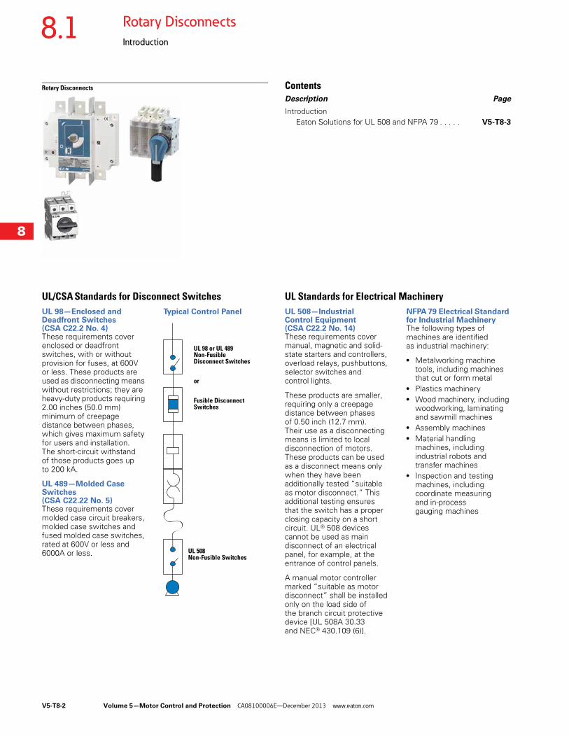
UL/CSA Standards for Disconnect SwitchesUL 98—Enclosed and Deadfront Switches (CSA C22.2 No. 4)These requirements cover enclosed or deadfront switches, with or without provision for fuses, at 600V or less. These products are used as disconnecting means without restrictions; they are heavy-duty products requiring 2.00 inches (50.0 mm) minimum of creepage distance between phases, which gives maximum safety for users and installation. The short-circuit withstand of those products goes up to 200 kA.
UL 489—Molded Case Switches (CSA C22.22 No. 5)These requirements cover molded case circuit breakers, molded case switches and fused molded case switches, rated at 600V or less and 6000A or less.
Typical Control Panel
UL 98 or UL 489Non-Fusible Disconnect Switches
or
Fusible Disconnect Switches
UL 508Non-Fusible Switches
UL Standards for Electrical MachineryUL 508—Industrial Control Equipment (CSA C22.2 No. 14)These requirements cover manual, magnetic and solid- state starters and controllers, overload relays, pushbuttons, selector switches andcontrol lights.
These products are smaller, requiring only a creepage distance between phases of 0.50 inch (12.7 mm). Their use as a disconnecting means is limited to local disconnection of motors. These products can be used as a disconnect means only when they have been additionally tested “suitable as motor disconnect.” This additional testing ensures that the switch has a proper closing capacity on a short circuit. UL® 508 devices cannot be used as main disconnect of an electrical panel, for example, at the entrance of control panels.
A manual motor controller marked “suitable as motor disconnect” shall be installed only on the load side of the branch circuit protective device [UL 508A 30.33 and NEC® 430.109 (6)].
NFPA 79 Electrical Standard for Industrial MachineryThe following types of machines are identified as industrial machinery:
● Metalworking machine tools, including machines that cut or form metal
● Plastics machinery● Wood machinery, including
woodworking, laminating and sawmill machines
● Assembly machines● Material handling
machines, including industrial robots and transfer machines
● Inspection and testing machines, including coordinate measuring and in-process gauging machines
Volume 5—Motor Control and Protection CA08100006E—December 2013 www.eaton.com V5-T8-3
8
8
8
8
8
8
8
8
8
8
8
8
8
8
8
8
8
8
8
8
8
8
8
8
8
8
8
8
8
8
8.1Rotary Disconnects
Introduction
Eaton Solutions for UL 508A and NFPA 79The changes in UL 508A and NFPA® 79 impact the design and construction of your equipment. Important modifications concern major safety issues, the disconnect means and the interlocking of the enclosure door.
The disconnect shall be operable independent of the door position.The disconnect must be operable, by qualified persons, independent of the door position without the use of accessory tools or devices.
Note: NFPA 79; Paragraph 5.3.3.1 (5) T.
An operating mechanism for the disconnecting means shall be operable independent of the door position without the use of accessory tools or devices.
Note: UL 508A; Paragraph 66.6.3 c.
The disconnect means is not closable with the enclosure door open, unless an interlock is operated by deliberate action.The interlocking means shall fulfill the following requirement: Prevent closing of the disconnect means while the enclosure door is open, unless an interlock is operated by deliberate action.
Note: NFPA 79; Paragraph 6.2.3.1.2.
The disconnecting means is not closable with the enclosure door open, unless an interlock is operated by deliberate action.
Note: UL 508A; Paragraph 66.1.5.
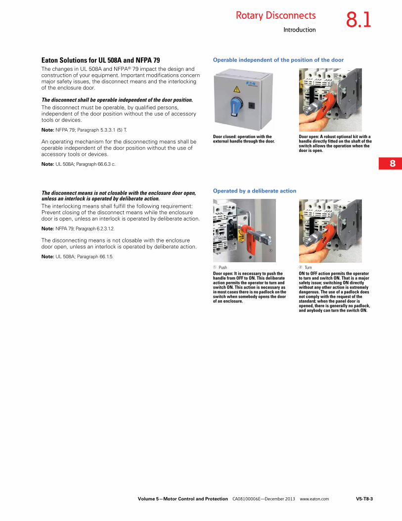
Operable independent of the position of the door
Door closed: operation with the external handle through the door.
Door open: A robust optional kit with a handle directly fitted on the shaft of the switch allows the operation when the door is open.
Operated by a deliberate action
1 PushDoor open: It is necessary to push the handle from OFF to ON. This deliberate action permits the operator to turn and switch ON. This action is necessary as in most cases there is no padlock on the switch when somebody opens the door of an enclosure.
2 TurnON to OFF action permits the operator to turn and switch ON. That is a major safety issue; switching ON directly without any other action is extremely dangerous. The use of a padlock does not comply with the request of the standard; when the panel door is opened, there is generally no padlock, and anybody can turn the switch ON.
1
2
V5-T8-4 Volume 5—Motor Control and Protection CA08100006E—December 2013 www.eaton.com
8
8
8
8
8
8
8
8
8
8
8
8
8
8
8
8
8
8
8
8
8
8
8
8
8
8
8
8
8
8
8.1 Rotary Disconnects
Introduction
The disconnect means shall be able to be locked in the OPEN position independent of the door position.The circuit disconnecting device shall be provided with a permanent means, permitting it to be locked in the OFF position only independent of the door position. When locked, remote as well as local closing shall be prevented.
Note: NFPA 79; Paragraph 5.3.3.1 (3).
An operating mechanism for the disconnecting means shall be able to be locked in the OFF position independent of the door position. When locked, closing of the disconnect is not possible.
Note: UL 508A; Paragraph 66.6.3 d.
The interlocking of the enclosure door shall be provided with means to defeat the interlock without removing the power.The interlocking means required by 66.1.5 shall be provided with all of the following:
● Means to defeat the interlock without removing power, and requires the use of a tool to operate
● Reactivated automatically when all the doors are closed
Note: Added 66.1.5.1 effective March 1, 2007. UL 508A; Paragraph 66.1.5.1.
NFPA 79; Paragraph 6.2.3.1.2 states that the [enclosure] interlocking means shall meet the following requirements:
● Use a device or tool to allow qualified persons to defeat the interlock
● Be reactivated automatically when the door is closed
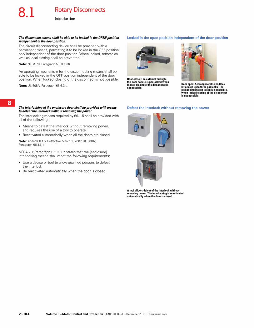
Locked in the open position independent of the door position
Door close: The external through- the-door handle is padlocked when locked closing of the disconnect is not possible.
Door open: A strong metallic padlock kit allows up to three padlocks. The padlocking means is easily accessible, when locked closing of the disconnect is not possible.
Defeat the interlock without removing the power
A tool allows defeat of the interlock without removing power. The interlocking is reactivated automatically when the door is closed.
Volume 5—Motor Control and Protection CA08100006E—December 2013 www.eaton.com V5-T8-5
8
8
8
8
8
8
8
8
8
8
8
8
8
8
8
8
8
8
8
8
8
8
8
8
8
8
8
8
8
8
8.2Rotary Disconnects
R5 Series (UL 508) Non-Fusible 16–80A
R5 Series Non-Fusible 16–80A ContentsDescription Page
R5 Series Non-Fusible 16–80AProduct Selection . . . . . . . . . . . . . . . . . . . . . . . V5-T8-6
Accessories . . . . . . . . . . . . . . . . . . . . . . . . . . . . V5-T8-6
Technical Data and Specifications . . . . . . . . . . . V5-T8-9
Dimensions . . . . . . . . . . . . . . . . . . . . . . . . . . . . V5-T8-10
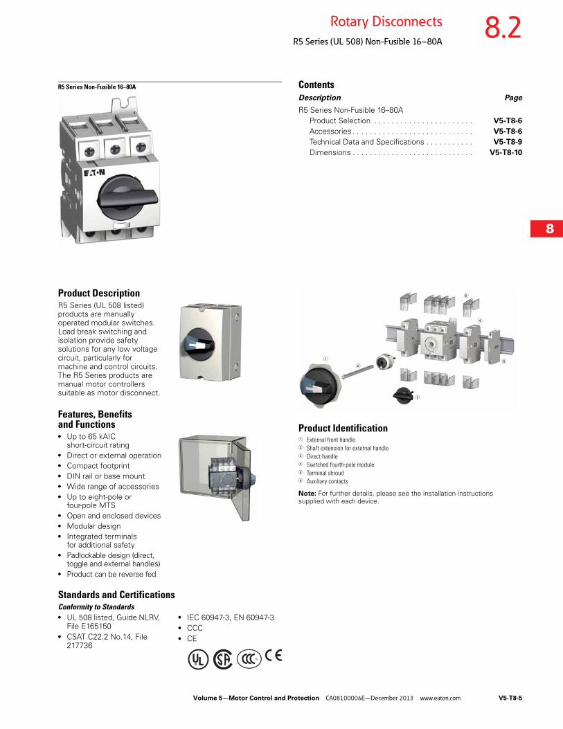
Product DescriptionR5 Series (UL 508 listed) products are manually operated modular switches. Load break switching and isolation provide safety solutions for any low voltage circuit, particularly for machine and control circuits. The R5 Series products are manual motor controllers suitable as motor disconnect.
Features, Benefits and Functions● Up to 65 kAIC
short-circuit rating● Direct or external operation● Compact footprint● DIN rail or base mount● Wide range of accessories● Up to eight-pole or
four-pole MTS● Open and enclosed devices● Modular design● Integrated terminals
for additional safety● Padlockable design (direct,
toggle and external handles)● Product can be reverse fed
Standards and CertificationsConformity to Standards● UL 508 listed, Guide NLRV,
File E165150● CSAT C22.2 No.14, File
217736
● IEC 60947-3, EN 60947-3● CCC● CE
Product Identification 1 External front handle2 Shaft extension for external handle3 Direct handle4 Switched fourth-pole module5 Terminal shroud6 Auxiliary contacts
Note: For further details, please see the installation instructions supplied with each device.
2
3
5
6
4
1
V5-T8-6 Volume 5—Motor Control and Protection CA08100006E—December 2013 www.eaton.com
8
8
8
8
8
8
8
8
8
8
8
8
8
8
8
8
8
8
8
8
8
8
8
8
8
8
8
8
8
8
8.2 Rotary Disconnects
R5 Series (UL 508) Non-Fusible 16–80A
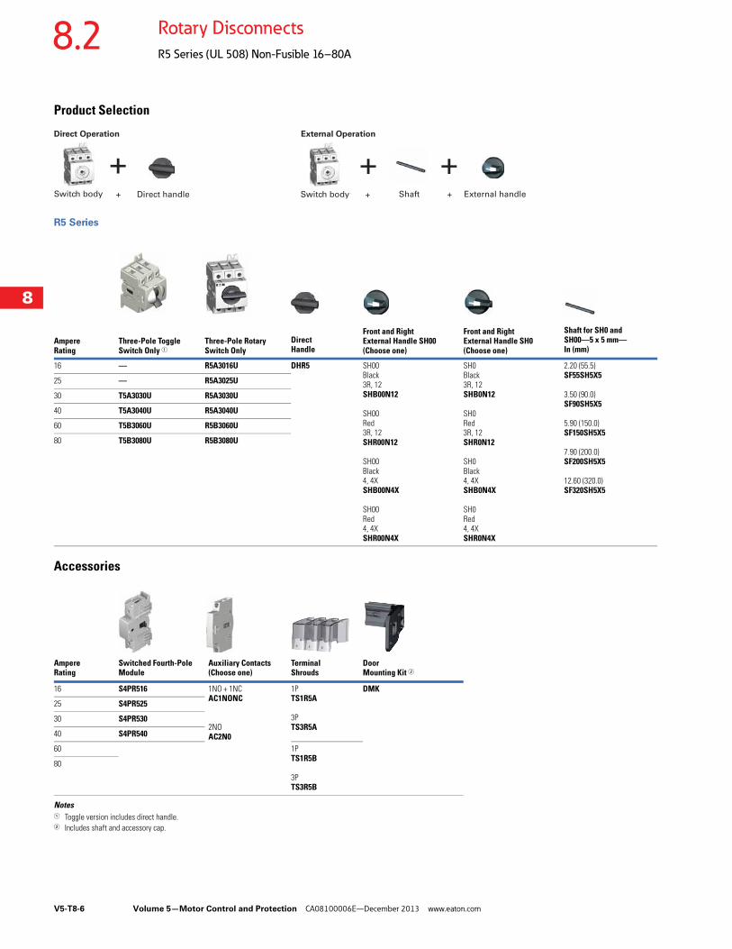
Product Selection
R5 Series
Accessories
Notes1 Toggle version includes direct handle.2 Includes shaft and accessory cap.
Ampere Rating
Three-Pole Toggle Switch Only 1
Three-Pole Rotary Switch Only
Direct Handle
Front and Right External Handle SH00 (Choose one)
Front and Right External Handle SH0(Choose one)
Shaft for SH0 and SH00—5 x 5 mm—In (mm)
16 — R5A3016U DHR5 SH00 Black 3R, 12 SHB00N12
SH00 Red 3R, 12 SHR00N12
SH00 Black 4, 4XSHB00N4X
SH00 Red 4, 4XSHR00N4X
SH0 Black 3R, 12 SHB0N12
SH0 Red 3R, 12 SHR0N12
SH0 Black 4, 4XSHB0N4X
SH0 Red 4, 4XSHR0N4X
2.20 (55.5)SF55SH5X5
3.50 (90.0)SF90SH5X5
5.90 (150.0) SF150SH5X5
7.90 (200.0)SF200SH5X5
12.60 (320.0)SF320SH5X5
25 — R5A3025U
30 T5A3030U R5A3030U
40 T5A3040U R5A3040U
60 T5B3060U R5B3060U
80 T5B3080U R5B3080U
+ + +Switch body Direct handle Switch body Shaft External handle+ + +
Direct Operation External Operation
Ampere Rating
Switched Fourth-Pole Module
Auxiliary Contacts (Choose one)
Terminal Shrouds
Door Mounting Kit 2
16 S4PR516 1NO + 1NC AC1NONC
2NO AC2N0
1P TS1R5A
3P TS3R5A
DMK
25 S4PR525
30 S4PR530
40 S4PR540
60 1PTS1R5B
3PTS3R5B
80
Volume 5—Motor Control and Protection CA08100006E—December 2013 www.eaton.com V5-T8-7
8
8
8
8
8
8
8
8
8
8
8
8
8
8
8
8
8
8
8
8
8
8
8
8
8
8
8
8
8
8
8.2Rotary Disconnects
R5 Series (UL 508) Non-Fusible 16–80A
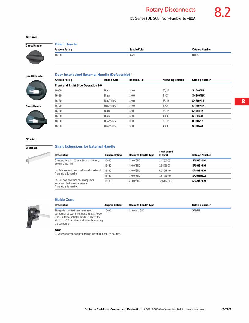
Handles
Direct Handle
Door Interlocked External Handle (Defeatable) 1
Shafts
Shaft Extensions for External Handle
Guide Cone
Note1 Allows door to be opened when switch is in the ON position.
Ampere Rating Handle Color Catalog Number
16–80 Black DHR5
Ampere Rating Handle Color Handle Size NEMA Type Rating Catalog Number
Front and Right Side Operation I–0
16–80 Black SH00 3R, 12 SHB00N12
16–80 Black SH00 4, 4X SHB00N4X
16–80 Red/Yellow SH00 3R, 12 SHR00N12
16–80 Red/Yellow SH00 4, 4X SHR00N4X
16–80 Black SH0 3R, 12 SHB0N12
16–80 Black SH0 4, 4X SHB0N4X
16–80 Red/Yellow SH0 3R, 12 SHR0N12
16–80 Red/Yellow SH0 4, 4X SHR0N4X
Description Ampere Rating Use with Handle TypeShaft Length In (mm) Catalog Number
Standard lengths: 55 mm, 90 mm, 150 mm, 200 mm, 320 mm
For 3/4-pole switches: shafts are for external front and side handle
For 6/8-pole switches and changeover switches: shafts are for external front and side handle
16–80 SH00/SH0 2.17 (55.0) SF055SH5X5
16–80 SH00/SH0 3.54 (90.0) SF090SH5X5
16–80 SH00/SH0 5.91 (150.0) SF150SH5X5
16–80 SH00/SH0 7.87 (200.0) SF2003H5X5
16–80 SH00/SH0 12.60 (320.0) SF320SH5X5
Description Ampere Rating Use with Handle Type Catalog Number
The guide cone facilitates an easier connection between the shaft and a Size 00 or Size 0 external selector handle. It allows the shaft up to 10 mm of vertical play when making the connection
16–80 SH00 and SH0 SFGAB
Direct Handle
Size 00 Handle
Size 0 Handle
Shaft 5 x 5
V5-T8-8 Volume 5—Motor Control and Protection CA08100006E—December 2013 www.eaton.com
8
8
8
8
8
8
8
8
8
8
8
8
8
8
8
8
8
8
8
8
8
8
8
8
8
8
8
8
8
8
8.2 Rotary Disconnects
R5 Series (UL 508) Non-Fusible 16–80A
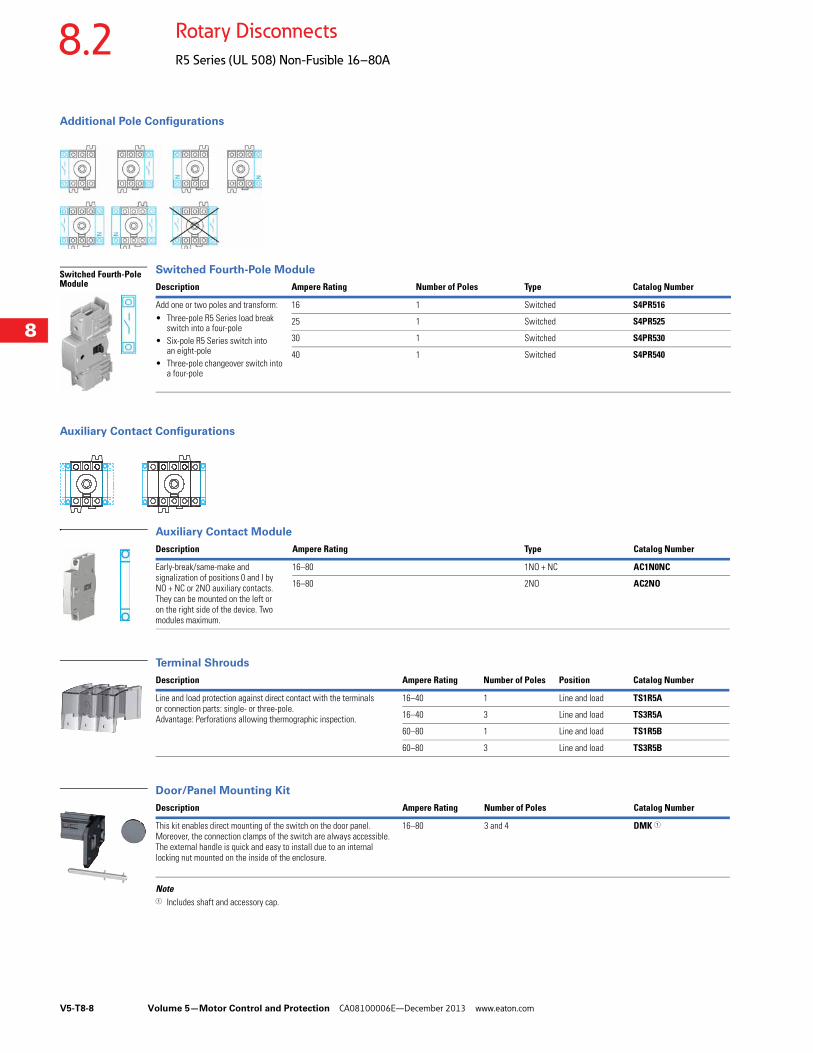
Additional Pole Configurations
Switched Fourth-Pole Module
Auxiliary Contact Configurations
Auxiliary Contact Module
Terminal Shrouds
Door/Panel Mounting Kit
Note1 Includes shaft and accessory cap.
Description Ampere Rating Number of Poles Type Catalog Number
Add one or two poles and transform:• Three-pole R5 Series load break
switch into a four-pole• Six-pole R5 Series switch into
an eight-pole• Three-pole changeover switch into
a four-pole
16 1 Switched S4PR516
25 1 Switched S4PR525
30 1 Switched S4PR530
40 1 Switched S4PR540
Switched Fourth-Pole Module
Description Ampere Rating Type Catalog Number
Early-break/same-make and signalization of positions 0 and I by NO + NC or 2NO auxiliary contacts.They can be mounted on the left or on the right side of the device. Two modules maximum.
16–80 1NO + NC AC1N0NC
16–80 2NO AC2NO
Description Ampere Rating Number of Poles Position Catalog Number
Line and load protection against direct contact with the terminals or connection parts: single- or three-pole.Advantage: Perforations allowing thermographic inspection.
16–40 1 Line and load TS1R5A
16–40 3 Line and load TS3R5A
60–80 1 Line and load TS1R5B
60–80 3 Line and load TS3R5B
Description Ampere Rating Number of Poles Catalog Number
This kit enables direct mounting of the switch on the door panel.Moreover, the connection clamps of the switch are always accessible.The external handle is quick and easy to install due to an internal locking nut mounted on the inside of the enclosure.
16–80 3 and 4 DMK 1
Volume 5—Motor Control and Protection CA08100006E—December 2013 www.eaton.com V5-T8-9
8
8
8
8
8
8
8
8
8
8
8
8
8
8
8
8
8
8
8
8
8
8
8
8
8
8
8
8
8
8
8.2Rotary Disconnects
R5 Series (UL 508) Non-Fusible 16–80A
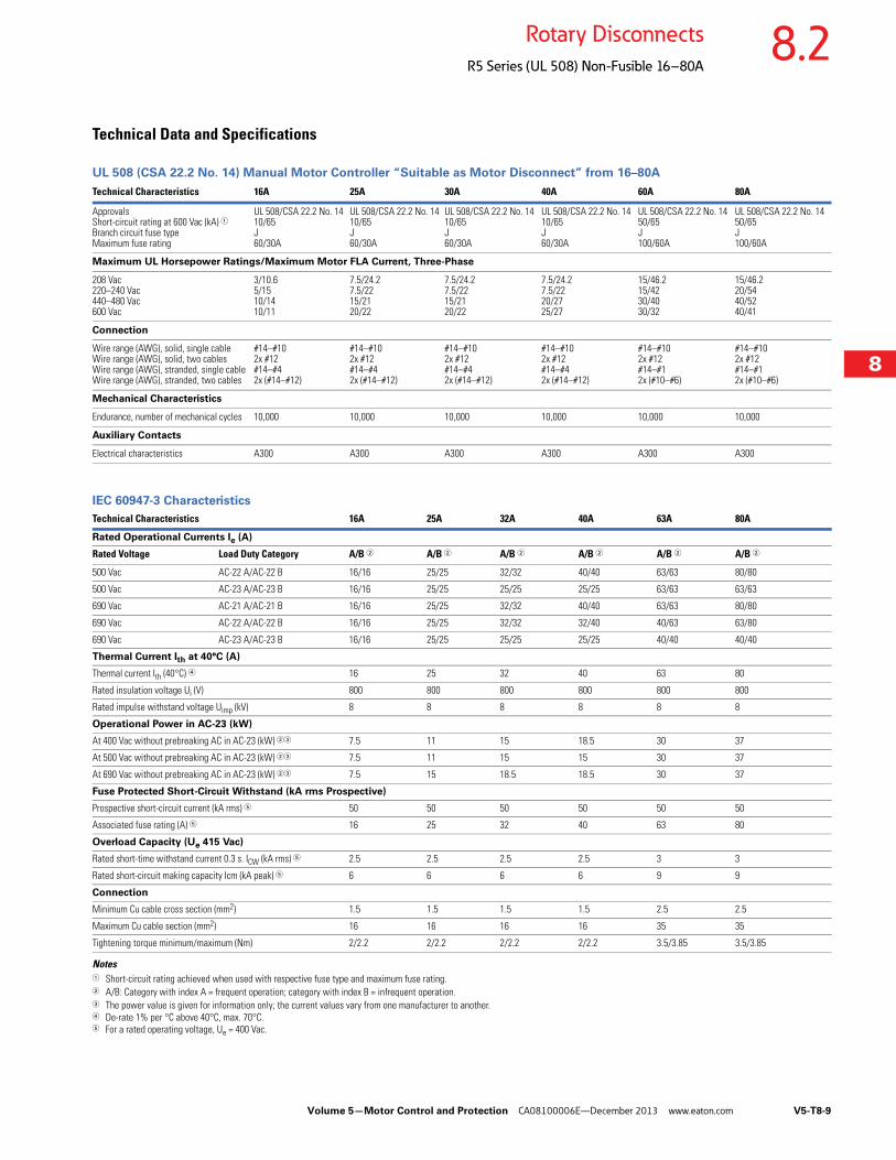
Technical Data and Specifications
UL 508 (CSA 22.2 No. 14) Manual Motor Controller “Suitable as Motor Disconnect” from 16–80A
IEC 60947-3 Characteristics
Notes1 Short-circuit rating achieved when used with respective fuse type and maximum fuse rating.2 A/B: Category with index A = frequent operation; category with index B = infrequent operation.3 The power value is given for information only; the current values vary from one manufacturer to another. 4 De-rate 1% per °C above 40°C, max. 70°C.5 For a rated operating voltage, Ue = 400 Vac.
Technical Characteristics 16A 25A 30A 40A 60A 80A
ApprovalsShort-circuit rating at 600 Vac (kA) 1Branch circuit fuse type Maximum fuse rating
UL 508/CSA 22.2 No. 1410/65J60/30A
UL 508/CSA 22.2 No. 1410/65J60/30A
UL 508/CSA 22.2 No. 1410/65J60/30A
UL 508/CSA 22.2 No. 1410/65J60/30A
UL 508/CSA 22.2 No. 1450/65J100/60A
UL 508/CSA 22.2 No. 1450/65J100/60A
Maximum UL Horsepower Ratings/Maximum Motor FLA Current, Three-Phase
208 Vac220–240 Vac440–480 Vac600 Vac
3/10.65/1510/1410/11
7.5/24.27.5/2215/2120/22
7.5/24.27.5/2215/2120/22
7.5/24.27.5/2220/2725/27
15/46.215/4230/4030/32
15/46.220/5440/5240/41
Connection
Wire range (AWG), solid, single cableWire range (AWG), solid, two cablesWire range (AWG), stranded, single cableWire range (AWG), stranded, two cables
#14–#102x #12#14–#42x (#14–#12)
#14–#102x #12#14–#42x (#14–#12)
#14–#102x #12#14–#42x (#14–#12)
#14–#102x #12#14–#42x (#14–#12)
#14–#102x #12#14–#12x (#10–#6)
#14–#102x #12#14–#12x (#10–#6)
Mechanical Characteristics
Endurance, number of mechanical cycles 10,000 10,000 10,000 10,000 10,000 10,000
Auxiliary Contacts
Electrical characteristics A300 A300 A300 A300 A300 A300
Technical Characteristics 16A 25A 32A 40A 63A 80A
Rated Operational Currents Ie (A)
Rated Voltage Load Duty Category A/B 2 A/B 2 A/B 2 A/B 2 A/B 2 A/B 2
500 Vac AC-22 A/AC-22 B 16/16 25/25 32/32 40/40 63/63 80/80
500 Vac AC-23 A/AC-23 B 16/16 25/25 25/25 25/25 63/63 63/63
690 Vac AC-21 A/AC-21 B 16/16 25/25 32/32 40/40 63/63 80/80
690 Vac AC-22 A/AC-22 B 16/16 25/25 32/32 32/40 40/63 63/80
690 Vac AC-23 A/AC-23 B 16/16 25/25 25/25 25/25 40/40 40/40
Thermal Current Ith at 40°C (A)
Thermal current Ith (40°C) 4 16 25 32 40 63 80
Rated insulation voltage Ui (V) 800 800 800 800 800 800
Rated impulse withstand voltage Uimp (kV) 8 8 8 8 8 8
Operational Power in AC-23 (kW)
At 400 Vac without prebreaking AC in AC-23 (kW) 23 7.5 11 15 18.5 30 37
At 500 Vac without prebreaking AC in AC-23 (kW) 23 7.5 11 15 15 30 37
At 690 Vac without prebreaking AC in AC-23 (kW) 23 7.5 15 18.5 18.5 30 37
Fuse Protected Short-Circuit Withstand (kA rms Prospective)
Prospective short-circuit current (kA rms) 5 50 50 50 50 50 50
Associated fuse rating (A) 5 16 25 32 40 63 80
Overload Capacity (Ue 415 Vac)
Rated short-time withstand current 0.3 s. ICW (kA rms) 5 2.5 2.5 2.5 2.5 3 3
Rated short-circuit making capacity Icm (kA peak) 5 6 6 6 6 9 9
Connection
Minimum Cu cable cross section (mm2) 1.5 1.5 1.5 1.5 2.5 2.5
Maximum Cu cable section (mm2) 16 16 16 16 35 35
Tightening torque minimum/maximum (Nm) 2/2.2 2/2.2 2/2.2 2/2.2 3.5/3.85 3.5/3.85
V5-T8-10 Volume 5—Motor Control and Protection CA08100006E—December 2013 www.eaton.com
8
8
8
8
8
8
8
8
8
8
8
8
8
8
8
8
8
8
8
8
8
8
8
8
8
8
8
8
8
8
8.2 Rotary Disconnects
R5 Series (UL 508) Non-Fusible 16–80A
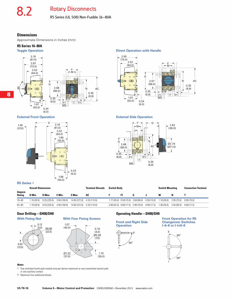
DimensionsApproximate Dimensions in Inches (mm)
R5 Series 16–80AToggle Operation
External Front Operation
Direct Operation with Handle
External Side Operation
R5 Series 2
Door Drilling—SH00/SH0With Fixing Nut With Four Fixing Screws
Notes1 One switched fourth-pole module (one per device maximum) or one unswitched neutral pole
or one auxiliary contact.2 Maximum four additional blocks.
Operating Handle—SH00/SH0Front Operation for R5
Front and Right Side Changeover SwitchesOperation I–0–II or I–I+II–II
2.68(68.0)
F
TM5
M
N
G
AC
3.19(81.0)
2.52(64.0)
0.24(6.0)
1.97(50.0)
2.87(73.0)
F1F1
0.35(8.8)
0.35(8.8)
90
E1.45
(37.0)
3.19(81.0)
2.52(64.0)
0.23(6.0)
1.96(50.0)
1.99(50.6)
F
TM5
M
N
G
AC
2.52(64.0)
0.24(6.0)
1.97(50.0)
2.95(75.0)
F1F1
2.67(68.0)
0.35(8.8)
0.35(8.8)
J
2.68(68.0)
F
T
M5
M
D
NG
AC
F1
0.35(8.8) F1
Ø2.79(Ø71.0)
0.35(8.8)
1.42(36.0)
Overall Dimensions Terminal Shrouds Switch Body Switch Mounting Connection TerminalAmpere Rating D Min. D Max. E Min. E Max. AC F F1 G J M N T
16–40 1.18 (30.0) 9.25 (235.0) 3.94 (100.0) 14.65 (372.0) 4.33 (110.0) 1.77 (45.0) 0.59 (15.0) 2.68 (68.0) 0.59 (15.0) 1.18 (30.0) 2.95 (75.0) 0.59 (15.0)
63–80 1.18 (30.0) 9.25 (235.0) 3.94 (100.0) 14.65 (372.0) 4.33 (110.0) 2.06 (52.5) 0.69 (17.5) 2.99 (76.0) 0.69 (17.5) 1.38 (35.0) 3.35 (85.0) 0.69 (17.5)
0.53(13.5)
0.12(3.0) Ø0.89
(22.5)
1.57(40.0)
Ø0.28(7.0)
Ø1.22(31.0)
1.10(28.0)
0.16(4.0)
90º
0º
I
I
II
90º
90º
Volume 5—Motor Control and Protection CA08100006E—December 2013 www.eaton.com V5-T8-11
8
8
8
8
8
8
8
8
8
8
8
8
8
8
8
8
8
8
8
8
8
8
8
8
8
8
8
8
8
8
8.3Rotary Disconnects
R9 Series (UL 98)
Non-Fusible 30–100A Compact ContentsDescription Page
Non-Fusible 30–100A CompactProduct Selection . . . . . . . . . . . . . . . . . . . . . . . V5-T8-12
Technical Data and Specifications . . . . . . . . . . . V5-T8-15
Dimensions . . . . . . . . . . . . . . . . . . . . . . . . . . . . V5-T8-16
Non-Fusible 100–1200A . . . . . . . . . . . . . . . . . . . . . V5-T8-18
Fusible 30–800A . . . . . . . . . . . . . . . . . . . . . . . . . . V5-T8-26
DC Rated Disconnects . . . . . . . . . . . . . . . . . . . . . V5-T8-45
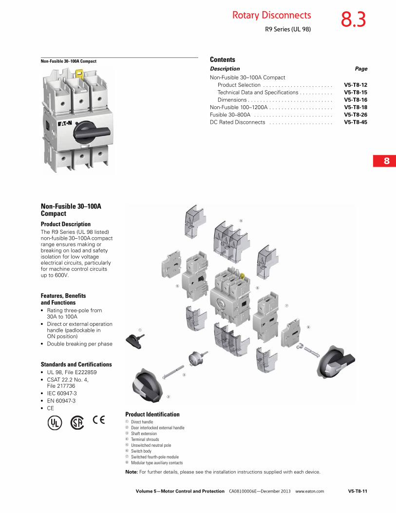
Non-Fusible 30–100A CompactProduct DescriptionThe R9 Series (UL 98 listed) non-fusible 30–100A compact range ensures making or breaking on load and safety isolation for low voltage electrical circuits, particularly for machine control circuits up to 600V.
Features, Benefits and Functions● Rating three-pole from
30A to 100A● Direct or external operation
handle (padlockable in ON position)
● Double breaking per phase
Standards and Certifications● UL 98, File E222859● CSAT 22.2 No. 4,
File 217736● IEC 60947-3● EN 60947-3● CE
Product Identification1 Direct handle2 Door interlocked external handle3 Shaft extension4 Terminal shrouds5 Unswitched neutral pole6 Switch body7 Switched fourth-pole module8 Modular type auxiliary contacts
Note: For further details, please see the installation instructions supplied with each device.
1
2
3
4
56
7
8

V5-T8-12 Volume 5—Motor Control and Protection CA08100006E—December 2013 www.eaton.com
8
8
8
8
8
8
8
8
8
8
8
8
8
8
8
8
8
8
8
8
8
8
8
8
8
8
8
8
8
8
8.3 Rotary Disconnects
R9 Series (UL 98)
Product Selection
R9 Series 30–100A
Ampere Rating(Frame)
Number of Poles
Switch Body Only
Direct Handle
Front and Right External Handle SH00 (Choose one)
Front and Right External Handle SH0 (Choose one)
Shaft for SH0 and SH00 Handles—In (mm)(Choose one)
Switched Fourth-Pole Module
Auxiliary Contacts (Choose one)
Terminal Shrouds (Choose one)
30(C-Frame)
3 R9C3030U DHR9 SH00 Black 3R, 12 SHB00N12
SH00 Red 3R, 12 SHR00N12
SH00 Black 4, 4X SHB00N4X
SH00 Red 4 4XSHR00N4X
SH0 Black 3R, 12 SHB0N12
SH0 Red 3R, 12 SHR0N12
SH0 Black 4, 4X SHB0N4X
SH0 Red 4 4XSHR0N4X
2.20 (55.5)SF55SH5X5
3.50 (90.0)SF90SH5X5
5.91 (150.0)SF150SH5X5
7.87 (200.0)SF200SH5X5
12.60 (320.0)SF320SH5X5
S4PR930 1NO + 1NCAC1NONC
2NO AC2N0
1P TS1R9
3P TS3R9CV
60(C-Frame)
3 R9C3060U S4PR960
100(C-Frame)
3 R9C3100U S4PR9100
+ + +Switch body Direct handle Switch body Shaft External handle+ + +
Direct Operation External Operation
Volume 5—Motor Control and Protection CA08100006E—December 2013 www.eaton.com V5-T8-13
8
8
8
8
8
8
8
8
8
8
8
8
8
8
8
8
8
8
8
8
8
8
8
8
8
8
8
8
8
8
8.3Rotary Disconnects
R9 Series (UL 98)
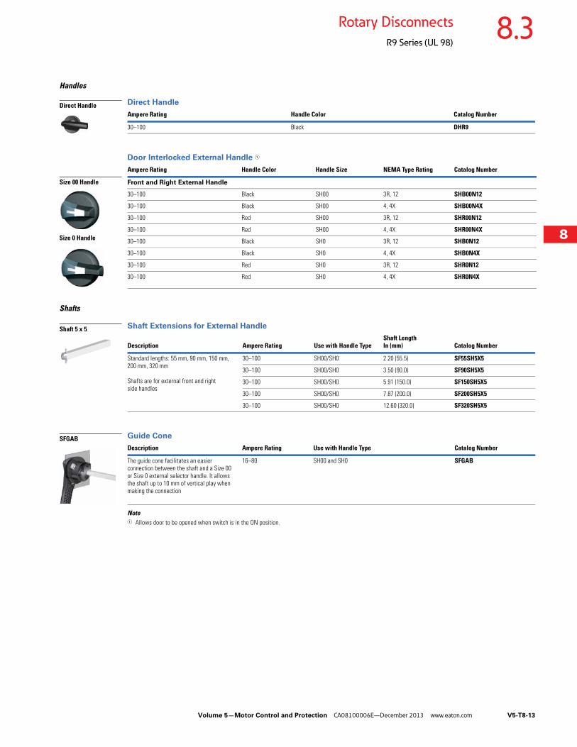
Handles
Direct Handle
Door Interlocked External Handle 1
Shafts
Shaft Extensions for External Handle
Guide Cone
Note1 Allows door to be opened when switch is in the ON position.
Ampere Rating Handle Color Catalog Number
30–100 Black DHR9
Ampere Rating Handle Color Handle Size NEMA Type Rating Catalog Number
Front and Right External Handle
30–100 Black SH00 3R, 12 SHB00N12
30–100 Black SH00 4, 4X SHB00N4X
30–100 Red SH00 3R, 12 SHR00N12
30–100 Red SH00 4, 4X SHR00N4X
30–100 Black SH0 3R, 12 SHB0N12
30–100 Black SH0 4, 4X SHB0N4X
30–100 Red SH0 3R, 12 SHR0N12
30–100 Red SH0 4, 4X SHR0N4X
Description Ampere Rating Use with Handle TypeShaft Length In (mm) Catalog Number
Standard lengths: 55 mm, 90 mm, 150 mm, 200 mm, 320 mm
Shafts are for external front and rightside handles
30–100 SH00/SH0 2.20 (55.5) SF55SH5X5
30–100 SH00/SH0 3.50 (90.0) SF90SH5X5
30–100 SH00/SH0 5.91 (150.0) SF150SH5X5
30–100 SH00/SH0 7.87 (200.0) SF200SH5X5
30–100 SH00/SH0 12.60 (320.0) SF320SH5X5
Description Ampere Rating Use with Handle Type Catalog Number
The guide cone facilitates an easier connection between the shaft and a Size 00 or Size 0 external selector handle. It allows the shaft up to 10 mm of vertical play when making the connection
16–80 SH00 and SH0 SFGAB
Direct Handle
Size 00 Handle
Size 0 Handle
Shaft 5 x 5
SFGAB
V5-T8-14 Volume 5—Motor Control and Protection CA08100006E—December 2013 www.eaton.com
8
8
8
8
8
8
8
8
8
8
8
8
8
8
8
8
8
8
8
8
8
8
8
8
8
8
8
8
8
8
8.3 Rotary Disconnects
R9 Series (UL 98)
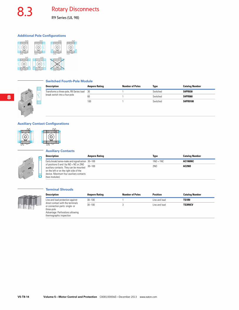
Additional Pole Configurations
Switched Fourth-Pole Module
Auxiliary Contact Configurations
Auxiliary Contacts
Terminal Shrouds
Description Ampere Rating Number of Poles Type Catalog Number
Transforms a three-pole, R9 Series load break switch into a four-pole
30 1 Switched S4PR930
60 1 Switched S4PR960
100 1 Switched S4PR9100
Description Ampere Rating Type Catalog Number
Early-break/same-make and signalization of positions 0 and I by NO + NC or 2NO auxiliary contacts. They can be mounted on the left or on the right side of the device. Maximum four auxiliary contacts (two modules)
30–100 1NO + 1NC AC1N0NC
30–100 2NO AC2NO
Description Ampere Rating Number of Poles Position Catalog Number
Line and load protection against direct contact with the terminals or connection parts: single- or three-poleAdvantage: Perforations allowing thermographic inspection
30–100 1 Line and load TS1R9
30–100 3 Line and load TS3R9CV
Volume 5—Motor Control and Protection CA08100006E—December 2013 www.eaton.com V5-T8-15
8
8
8
8
8
8
8
8
8
8
8
8
8
8
8
8
8
8
8
8
8
8
8
8
8
8
8
8
8
8
8.3Rotary Disconnects
R9 Series (UL 98)
Technical Data and Specifications
UL and CSA Characteristics
UL 98/CSA 22.2 No. 4
IEC 60647-3 Characteristics
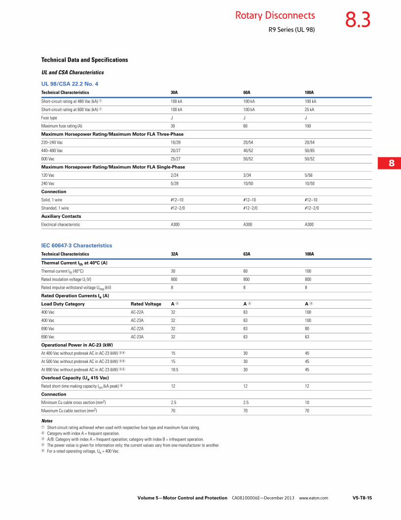
Notes1 Short-circuit rating achieved when used with respective fuse type and maximum fuse rating.2 Category with index A = frequent operation.3 A/B: Category with index A = frequent operation; category with index B = infrequent operation.4 The power value is given for information only; the current values vary from one manufacturer to another.5 For a rated operating voltage, Ue = 400 Vac.
Technical Characteristics 30A 60A 100A
Short-circuit rating at 480 Vac (kA) 1 100 kA 100 kA 100 kA
Short-circuit rating at 600 Vac (kA) 1 100 kA 100 kA 25 kA
Fuse type J J J
Maximum fuse rating (A) 30 60 100
Maximum Horsepower Rating/Maximum Motor FLA Three-Phase
220–240 Vac 10/28 20/54 20/54
440–480 Vac 20/27 40/52 50/65
600 Vac 25/27 50/52 50/52
Maximum Horsepower Rating/Maximum Motor FLA Single-Phase
120 Vac 2/24 3/34 5/56
240 Vac 5/28 10/50 10/50
Connection
Solid, 1 wire #12–10 #12–10 #12–10
Stranded, 1 wire #12–2/0 #12–2/0 #12–2/0
Auxiliary Contacts
Electrical characteristic A300 A300 A300
Technical Characteristics 32A 63A 100A
Thermal Current Ith at 40°C (A)
Thermal current Ith (40°C) 30 60 100
Rated insulation voltage Ui (V) 800 800 800
Rated impulse withstand voltage Uimp (kV) 8 8 8
Rated Operation Currents Ie (A)
Load Duty Category Rated Voltage A 2 A 2 A 2
400 Vac AC-22A 32 63 100
400 Vac AC-23A 32 63 100
690 Vac AC-22A 32 63 80
690 Vac AC-23A 32 63 63
Operational Power in AC-23 (kW)
At 400 Vac without prebreak AC in AC-23 (kW) 34 15 30 45
At 500 Vac without prebreak AC in AC-23 (kW) 34 15 30 45
At 690 Vac without prebreak AC in AC-23 (kW) 34 18.5 30 45
Overload Capacity (Ue 415 Vac)
Rated short-time making capacity Icm (kA peak) 5 12 12 12
Connection
Minimum Cu cable cross section (mm2) 2.5 2.5 10
Maximum Cu cable section (mm2) 70 70 70
V5-T8-16 Volume 5—Motor Control and Protection CA08100006E—December 2013 www.eaton.com
8
8
8
8
8
8
8
8
8
8
8
8
8
8
8
8
8
8
8
8
8
8
8
8
8
8
8
8
8
8
8.3 Rotary Disconnects
R9 Series (UL 98)
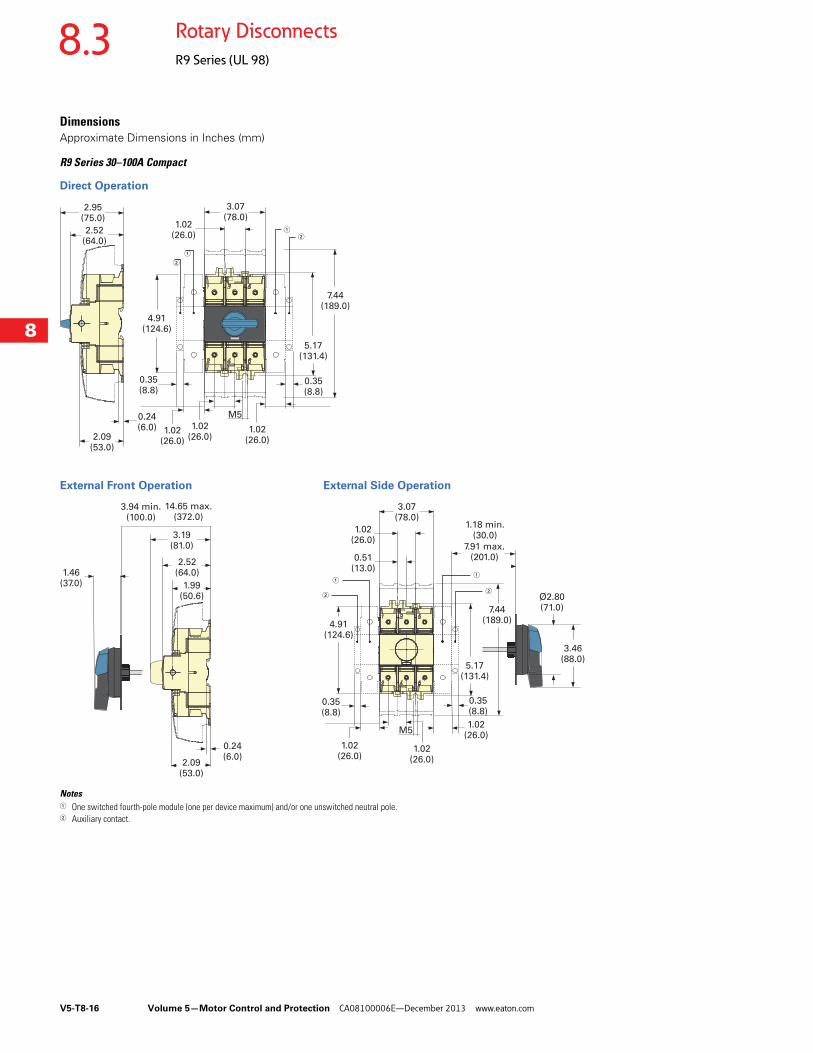
DimensionsApproximate Dimensions in Inches (mm)
R9 Series 30–100A Compact
Direct Operation
External Front Operation External Side Operation
Notes1 One switched fourth-pole module (one per device maximum) and/or one unswitched neutral pole.2 Auxiliary contact.
2.95(75.0)
2.52(64.0)
2.09(53.0)
0.24(6.0)
4.91(124.6)
5.17(131.4)
7.44(189.0)
1.02(26.0)
3.07(78.0)
0.35(8.8)
1.02(26.0)
M5
26.00(660.4)
1.02(26.0)
1.02(26.0)
0.35(8.8)
1
2
12
0.51(13.0)
4.91(124.6)
5.17(131.4)
7.44(189.0)
1.02(26.0)
3.07(78.0)
0.35(8.8)
1.02(26.0)
M5
3.46(88.0)
Ø2.80(71.0)
1.18 min.(30.0)
7.91 max.(201.0)
0.35(8.8)
1.02(26.0)
1.02(26.0)
1.46(37.0)
3.94 min.(100.0)
3.19(81.0)
2.52(64.0)
2.09(53.0)
0.24(6.0)
1.99(50.6)
14.65 max.(372.0)
1
2
1
2
Volume 5—Motor Control and Protection CA08100006E—December 2013 www.eaton.com V5-T8-17
8
8
8
8
8
8
8
8
8
8
8
8
8
8
8
8
8
8
8
8
8
8
8
8
8
8
8
8
8
8
8.3Rotary Disconnects
R9 Series (UL 98)
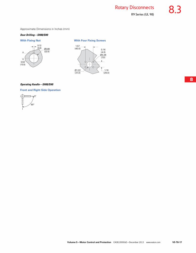
Approximate Dimensions in Inches (mm)
Door Drilling—SH00/SH0
With Fixing Nut With Four Fixing Screws
Operating Handle—SH00/SH0
Front and Right Side Operation
0.53(13.5)
0.12(3.0) Ø0.89
(22.5)
1.57(40.0)
Ø0.28(7.0)
Ø1.22(31.0)
1.10(28.0)
0.16(4.0)
90º
0º
I
V5-T8-18 Volume 5—Motor Control and Protection CA08100006E—December 2013 www.eaton.com
8
8
8
8
8
8
8
8
8
8
8
8
8
8
8
8
8
8
8
8
8
8
8
8
8
8
8
8
8
8
8.3 Rotary Disconnects
R9 Series (UL 98)
Non-Fusible 100–1200A ContentsDescription Page
Non-Fusible 30–100A Compact . . . . . . . . . . . . . . . V5-T8-11
Non-Fusible 100–1200AProduct Selection . . . . . . . . . . . . . . . . . . . . . . . V5-T8-19
Accessories. . . . . . . . . . . . . . . . . . . . . . . . . . . . V5-T8-20
Technical Data and Specifications . . . . . . . . . . . V5-T8-22
Dimensions . . . . . . . . . . . . . . . . . . . . . . . . . . . V5-T8-23
Fusible 30–800A . . . . . . . . . . . . . . . . . . . . . . . . . . V5-T8-26
DC Rated Disconnects . . . . . . . . . . . . . . . . . . . . . V5-T8-45
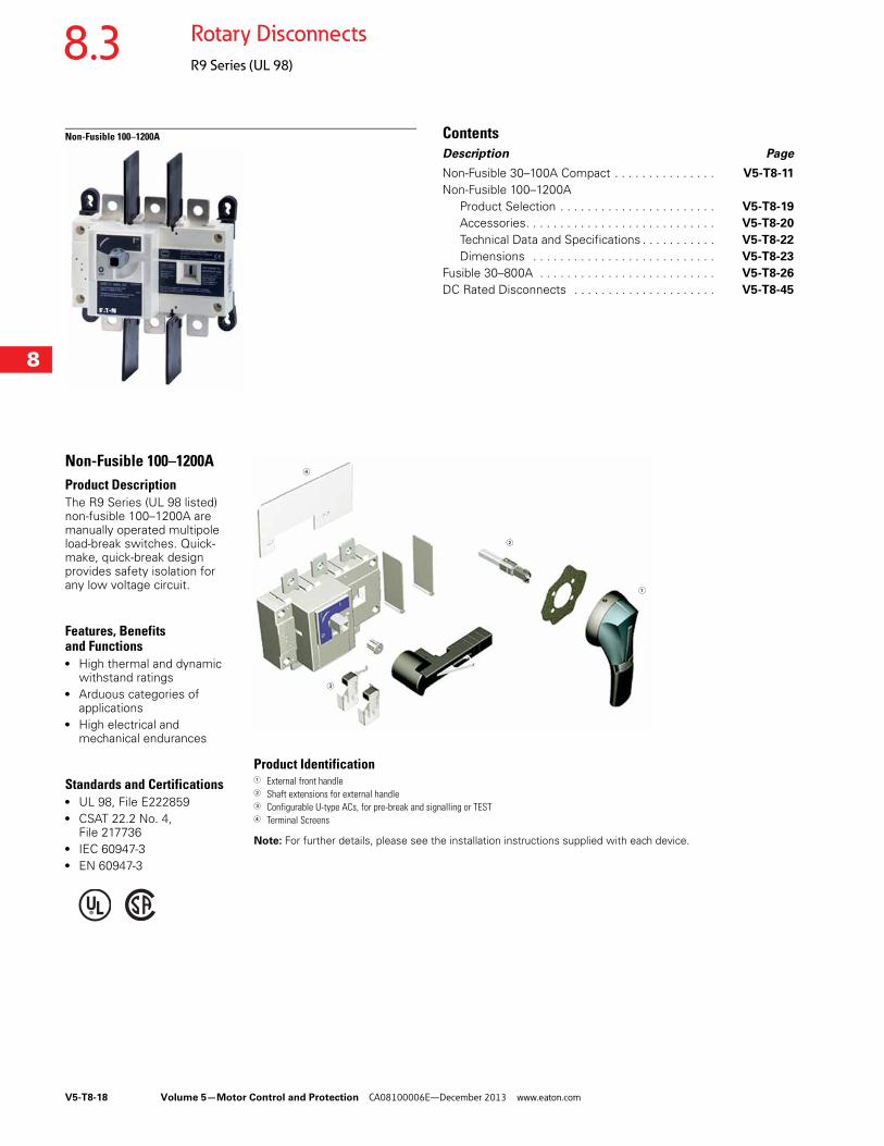
Non-Fusible 100–1200AProduct DescriptionThe R9 Series (UL 98 listed) non-fusible 100–1200A are manually operated multipole load-break switches. Quick-make, quick-break design provides safety isolation for any low voltage circuit.
Features, Benefits and Functions● High thermal and dynamic
withstand ratings● Arduous categories of
applications● High electrical and
mechanical endurances
Standards and Certifications● UL 98, File E222859● CSAT 22.2 No. 4,
File 217736● IEC 60947-3● EN 60947-3
Product Identification1 External front handle2 Shaft extensions for external handle3 Configurable U-type ACs, for pre-break and signalling or TEST4 Terminal Screens
Note: For further details, please see the installation instructions supplied with each device.
1
2
3
4

Volume 5—Motor Control and Protection CA08100006E—December 2013 www.eaton.com V5-T8-19
8
8
8
8
8
8
8
8
8
8
8
8
8
8
8
8
8
8
8
8
8
8
8
8
8
8
8
8
8
8
8.3Rotary Disconnects
R9 Series (UL 98)
Product Selection
R9 Series Non-Fusible 100–1200A
Notes1 Top (line side) supplied as standard.2 Auxiliary contact requires holder (catalog number ACHFG) when used on F and G-Frame switches (non-fusible 600–1200A).3 Each catalog number is for line or load side. For both line and load, please order two sets.4 FS suffix = Finger Safe.
Ampere Rating(Frame)
Number of Poles
Switch Body Only
Direct Handle
Door Interlocked External Pistol Handle (Choose one)
Shaft Extensions for External Handle—In (mm)(Choose one)
Auxiliary Contacts
Terminal Screens(Choose one)
Terminal Lugs 3
100(D-Frame)
3 R9D3100U DHR9DE Size 2, Black1, 3R, 12DefeatablePHB2N12F
Size 2, Red1, 3R, 12DefeatablePHR2N12F
Size 2, Black4, 4XDefeatablePHB2N4XF
Size 2, Red4, 4XDefeatablePHR2N4XF
7.90 (200.0)SF200PH10X10
12.60 (320.0)SF320PH10X10
15.70 (400.0)SF400PH10X10
19.70 (500.0)SF500PH10X10
1NO + 1NCAC1N0NCDEAC1N0NCDELL
2NO + 2NCAC2N0NCDEAC2N0NCDELL
3-pole, Line side onlyTS3R9DT
3-pole, Load side onlyTS3R9DB
4-pole, Line or load sideTS4R9DTB
LK3R9DL
4 R9D4100U LK4R9DL
200(D-Frame)
3 R9D3200U LK3R9DL
4 R9D4200U LK4R9DL
400(E-Frame)
3 R9E3400U 3-pole, Line side onlyTS3R9ET
3-pole, Load side onlyTS3R9EB
4-pole, Line or load sideTS4R9ETB
LK3R9EM
4 R9E4400U LK4R9EM
600(F-Frame)
3 R9F3600U DHR9FG Size 3, Black4, 4XDefeatablePHB3N4XF
Size 3, Red4, 4X DefeatablePHR3N4XF
Size 4, Black4, 4XDefeatablePHB4N4XF
Size 4, Red4, 4XDefeatablePHR4N4XF
7.90 (200.0)SF200PH15X12
12.60 (320.0)SF320PH15X12
1.70 (400.0)SF400PH15X12
1NO AC U TypeAC1N0R9 2
1NC AC U TypeAC1NCR9 2
TS3R9F 1 LK3R9FN
4 R9F4600U TS4R9F 1 LK4R9FN
800(G-Frame)
3 R9G3800U TS3R9FFS 4 LK6R9G
4 R9G4800U TS3R9G 1 LK8R9G
1000(G-Frame)
3 R9G31000U TS4R9G 1
4 R9G41000U TS3R9GFS 4
1200(G-Frame)
3 R9G31200U
4 R9G41200U
+ + +Switch body Direct handle Switch body Shaft External handle+ + +
Direct Operation External Operation
V5-T8-20 Volume 5—Motor Control and Protection CA08100006E—December 2013 www.eaton.com
8
8
8
8
8
8
8
8
8
8
8
8
8
8
8
8
8
8
8
8
8
8
8
8
8
8
8
8
8
8
8.3 Rotary Disconnects
R9 Series (UL 98)
Accessories
Direct Handle
Door Interlocked External Handle—Front Operation
Shaft Extensions for External Front Handle
Shaft Length Minimum Dimensions (X)—Inches (mm)
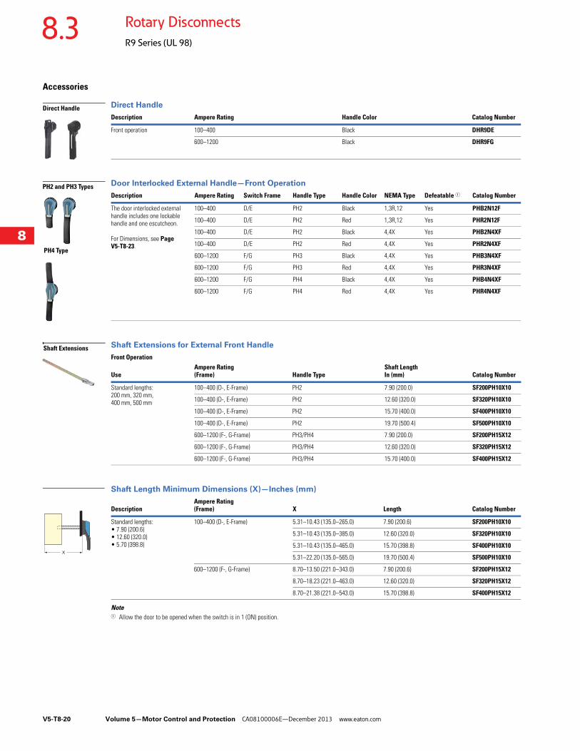
Note1 Allow the door to be opened when the switch is in 1 (ON) position.
Description Ampere Rating Handle Color Catalog Number
Front operation 100–400 Black DHR9DE
600–1200 Black DHR9FG
Description Ampere Rating Switch Frame Handle Type Handle Color NEMA Type Defeatable 1 Catalog Number
The door interlocked external handle includes one lockable handle and one escutcheon.
For Dimensions, see Page V5-T8-23.
100–400 D/E PH2 Black 1,3R,12 Yes PHB2N12F
100–400 D/E PH2 Red 1,3R,12 Yes PHR2N12F
100–400 D/E PH2 Black 4,4X Yes PHB2N4XF
100–400 D/E PH2 Red 4,4X Yes PHR2N4XF
600–1200 F/G PH3 Black 4,4X Yes PHB3N4XF
600–1200 F/G PH3 Red 4,4X Yes PHR3N4XF
600–1200 F/G PH4 Black 4,4X Yes PHB4N4XF
600–1200 F/G PH4 Red 4,4X Yes PHR4N4XF
Front Operation
UseAmpere Rating (Frame) Handle Type
Shaft Length In (mm) Catalog Number
Standard lengths:200 mm, 320 mm, 400 mm, 500 mm
100–400 (D-, E-Frame) PH2 7.90 (200.0) SF200PH10X10
100–400 (D-, E-Frame) PH2 12.60 (320.0) SF320PH10X10
100–400 (D-, E-Frame) PH2 15.70 (400.0) SF400PH10X10
100–400 (D-, E-Frame) PH2 19.70 (500.4) SF500PH10X10
600–1200 (F-, G-Frame) PH3/PH4 7.90 (200.0) SF200PH15X12
600–1200 (F-, G-Frame) PH3/PH4 12.60 (320.0) SF320PH15X12
600–1200 (F-, G-Frame) PH3/PH4 15.70 (400.0) SF400PH15X12
DescriptionAmpere Rating(Frame) X Length Catalog Number
Standard lengths:• 7.90 (200.6)• 12.60 (320.0)• 5.70 (398.8)
100–400 (D-, E-Frame) 5.31–10.43 (135.0–265.0) 7.90 (200.6) SF200PH10X10
5.31–10.43 (135.0–385.0) 12.60 (320.0) SF320PH10X10
5.31–10.43 (135.0–465.0) 15.70 (398.8) SF400PH10X10
5.31–22.20 (135.0–565.0) 19.70 (500.4) SF500PH10X10
600–1200 (F-, G-Frame) 8.70–13.50 (221.0–343.0) 7.90 (200.6) SF200PH15X12
8.70–18.23 (221.0–463.0) 12.60 (320.0) SF320PH15X12
8.70–21.38 (221.0–543.0) 15.70 (398.8) SF400PH15X12
Direct Handle
PH2 and PH3 Types
PH4 Type
Shaft Extensions
X
Volume 5—Motor Control and Protection CA08100006E—December 2013 www.eaton.com V5-T8-21
8
8
8
8
8
8
8
8
8
8
8
8
8
8
8
8
8
8
8
8
8
8
8
8
8
8
8
8
8
8
8.3Rotary Disconnects
R9 Series (UL 98)
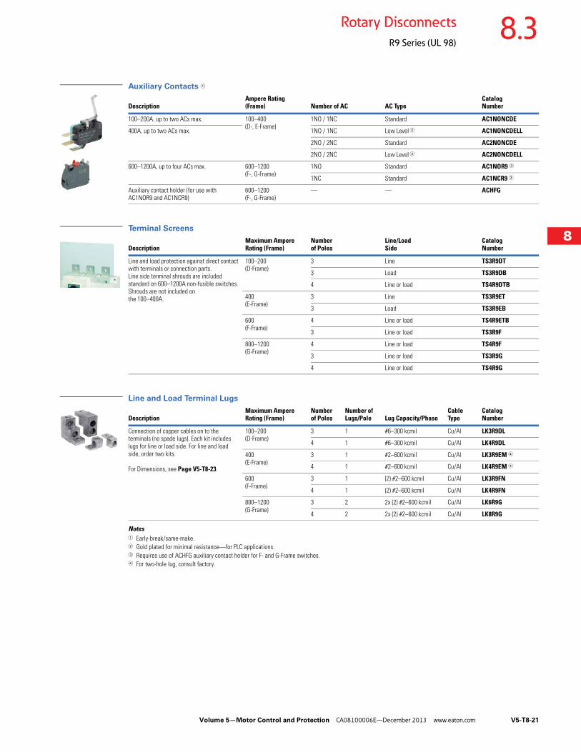
Auxiliary Contacts 1
Terminal Screens
Line and Load Terminal Lugs
Notes1 Early-break/same-make.2 Gold plated for minimal resistance—for PLC applications.3 Requires use of ACHFG auxiliary contact holder for F- and G-Frame switches.4 For two-hole lug, consult factory.
DescriptionAmpere Rating(Frame) Number of AC AC Type
Catalog Number
100–200A, up to two ACs max. 100–400(D-, E-Frame)
1NO / 1NC Standard AC1NONCDE
400A, up to two ACs max. 1NO / 1NC Low Level 2 AC1NONCDELL
2NO / 2NC Standard AC2NONCDE
2NO / 2NC Low Level 2 AC2NONCDELL
600–1200A, up to four ACs max. 600–1200(F-, G-Frame)
1NO Standard AC1NOR9 3
1NC Standard AC1NCR9 3
Auxiliary contact holder (for use with AC1NOR9 and AC1NCR9)
600–1200(F-, G-Frame)
— — ACHFG
DescriptionMaximum Ampere Rating (Frame)
Number of Poles
Line/Load Side
Catalog Number
Line and load protection against direct contact with terminals or connection parts.Line side terminal shrouds are included standard on 600–1200A non-fusible switches. Shrouds are not included on the 100–400A.
100–200(D-Frame)
3 Line TS3R9DT
3 Load TS3R9DB
4 Line or load TS4R9DTB
400(E-Frame)
3 Line TS3R9ET
3 Load TS3R9EB
600(F-Frame)
4 Line or load TS4R9ETB
3 Line or load TS3R9F
800–1200(G-Frame)
4 Line or load TS4R9F
3 Line or load TS3R9G
4 Line or load TS4R9G
DescriptionMaximum Ampere Rating (Frame)
Number of Poles
Number of Lugs/Pole Lug Capacity/Phase
Cable Type
Catalog Number
Connection of copper cables on to the terminals (no spade lugs). Each kit includes lugs for line or load side. For line and load side, order two kits.
For Dimensions, see Page V5-T8-23.
100–200(D-Frame)
3 1 #6–300 kcmil Cu/Al LK3R9DL
4 1 #6–300 kcmil Cu/Al LK4R9DL
400(E-Frame)
3 1 #2–600 kcmil Cu/Al LK3R9EM 4
4 1 #2–600 kcmil Cu/Al LK4R9EM 4
600(F-Frame)
3 1 (2) #2–600 kcmil Cu/Al LK3R9FN
4 1 (2) #2–600 kcmil Cu/Al LK4R9FN
800–1200(G-Frame)
3 2 2x (2) #2–600 kcmil Cu/Al LK6R9G
4 2 2x (2) #2–600 kcmil Cu/Al LK8R9G
V5-T8-22 Volume 5—Motor Control and Protection CA08100006E—December 2013 www.eaton.com
8
8
8
8
8
8
8
8
8
8
8
8
8
8
8
8
8
8
8
8
8
8
8
8
8
8
8
8
8
8
8.3 Rotary Disconnects
R9 Series (UL 98)
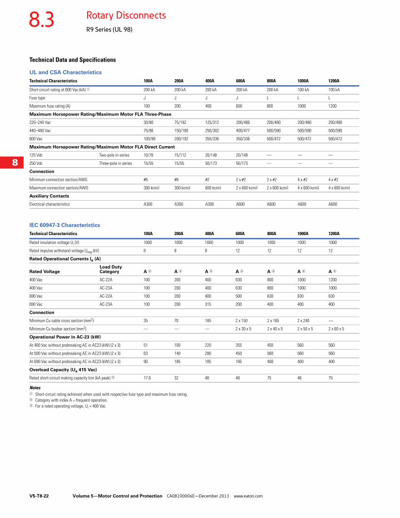
Technical Data and Specifications
UL and CSA Characteristics
IEC 60947-3 Characteristics
Notes1 Short-circuit rating achieved when used with respective fuse type and maximum fuse rating.2 Category with index A = frequent operation.3 For a rated operating voltage, Ui = 400 Vac.
Technical Characteristics 100A 200A 400A 600A 800A 1000A 1200A
Short circuit rating at 600 Vac (kA) 1 200 kA 200 kA 200 kA 200 kA 200 kA 100 kA 100 kA
Fuse type J J J J L L L
Maximum fuse rating (A) 100 200 400 600 800 1000 1200
Maximum Horsepower Rating/Maximum Motor FLA Three-Phase
220–240 Vac 30/80 75/192 125/312 200/480 200/480 200/480 200/480
440–480 Vac 75/96 150/180 250/302 400/477 500/590 500/590 500/590
600 Vac 100/99 200/192 350/336 350/336 500/472 500/472 500/472
Maximum Horsepower Rating/Maximum Motor FLA Direct Current
125 Vdc Two-pole in series 10/76 15/112 20/148 20/148 — — —
250 Vdc Three-pole in series 15/55 15/55 50/173 50/173 — — —
Connection
Minimum connection section/AWG #6 #6 #2 2 x #2 2 x #2 4 x #2 4 x #2
Maximum connection section/AWG 300 kcmil 300 kcmil 600 kcmil 2 x 600 kcmil 2 x 600 kcmil 4 x 600 kcmil 4 x 600 kcmil
Auxiliary Contacts
Electrical characteristics A300 A300 A300 A600 A600 A600 A600
Technical Characteristics 100A 200A 400A 600A 800A 1000A 1200A
Rated insulation voltage Ui (V) 1000 1000 1000 1000 1000 1000 1000
Rated impulse withstand voltage Uimp (kV) 8 8 8 12 12 12 12
Rated Operational Currents Ie (A)
Rated VoltageLoad Duty Category A 2 A 2 A 2 A 2 A 2 A 2 A 2
400 Vac AC-22A 100 200 400 630 800 1000 1200
400 Vac AC-23A 100 200 400 630 800 1000 1000
690 Vac AC-22A 100 200 400 500 630 630 630
690 Vac AC-23A 100 200 315 200 400 400 400
Connection
Minimum Cu cable cross section (mm2) 35 70 185 2 x 150 2 x 185 2 x 240 —
Minimum Cu busbar section (mm2) — — — 2 x 30 x 5 2 x 40 x 5 2 x 50 x 5 2 x 60 x 5
Operational Power in AC-23 (kW)
At 400 Vac without prebreaking AC in AC23 (kW) (2 x 3) 51 100 220 355 450 560 560
At 500 Vac without prebreaking AC in AC23 (kW) (2 x 3) 63 140 280 450 560 560 560
At 690 Vac without prebreaking AC in AC23 (kW) (2 x 3) 90 185 185 185 400 400 400
Overload Capacity (Ue 415 Vac)
Rated short-circuit making capacity Icm (kA peak) 3 17.6 32 48 48 75 48 75
Volume 5—Motor Control and Protection CA08100006E—December 2013 www.eaton.com V5-T8-23
8
8
8
8
8
8
8
8
8
8
8
8
8
8
8
8
8
8
8
8
8
8
8
8
8
8
8
8
8
8
8.3Rotary Disconnects
R9 Series (UL 98)
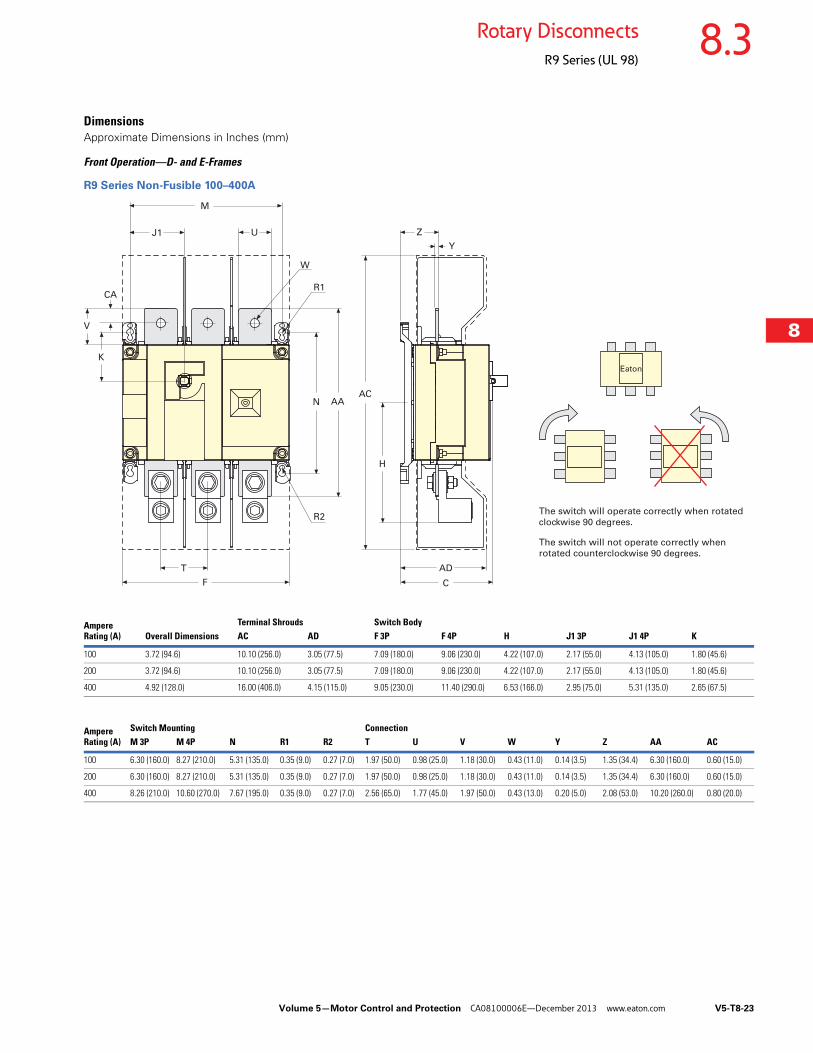
DimensionsApproximate Dimensions in Inches (mm)
Front Operation—D- and E-Frames
R9 Series Non-Fusible 100–400A
Y
AC
K
CA
V
N AA
H
ZJ1 U
R1
M
ADT
F C
R2
W
The switch will operate correctly when rotated
clockwise 90 degrees.
The switch will not operate correctly when
rotated counterclockwise 90 degrees.
Ampere Rating (A) Overall Dimensions
Terminal Shrouds Switch BodyAC AD F 3P F 4P H J1 3P J1 4P K
100 3.72 (94.6) 10.10 (256.0) 3.05 (77.5) 7.09 (180.0) 9.06 (230.0) 4.22 (107.0) 2.17 (55.0) 4.13 (105.0) 1.80 (45.6)
200 3.72 (94.6) 10.10 (256.0) 3.05 (77.5) 7.09 (180.0) 9.06 (230.0) 4.22 (107.0) 2.17 (55.0) 4.13 (105.0) 1.80 (45.6)
400 4.92 (128.0) 16.00 (406.0) 4.15 (115.0) 9.05 (230.0) 11.40 (290.0) 6.53 (166.0) 2.95 (75.0) 5.31 (135.0) 2.65 (67.5)
Ampere Rating (A)
Switch Mounting ConnectionM 3P M 4P N R1 R2 T U V W Y Z AA AC
100 6.30 (160.0) 8.27 (210.0) 5.31 (135.0) 0.35 (9.0) 0.27 (7.0) 1.97 (50.0) 0.98 (25.0) 1.18 (30.0) 0.43 (11.0) 0.14 (3.5) 1.35 (34.4) 6.30 (160.0) 0.60 (15.0)
200 6.30 (160.0) 8.27 (210.0) 5.31 (135.0) 0.35 (9.0) 0.27 (7.0) 1.97 (50.0) 0.98 (25.0) 1.18 (30.0) 0.43 (11.0) 0.14 (3.5) 1.35 (34.4) 6.30 (160.0) 0.60 (15.0)
400 8.26 (210.0) 10.60 (270.0) 7.67 (195.0) 0.35 (9.0) 0.27 (7.0) 2.56 (65.0) 1.77 (45.0) 1.97 (50.0) 0.43 (13.0) 0.20 (5.0) 2.08 (53.0) 10.20 (260.0) 0.80 (20.0)
V5-T8-24 Volume 5—Motor Control and Protection CA08100006E—December 2013 www.eaton.com
8
8
8
8
8
8
8
8
8
8
8
8
8
8
8
8
8
8
8
8
8
8
8
8
8
8
8
8
8
8
8.3 Rotary Disconnects
R9 Series (UL 98)
Approximate Dimensions in Inches (mm)
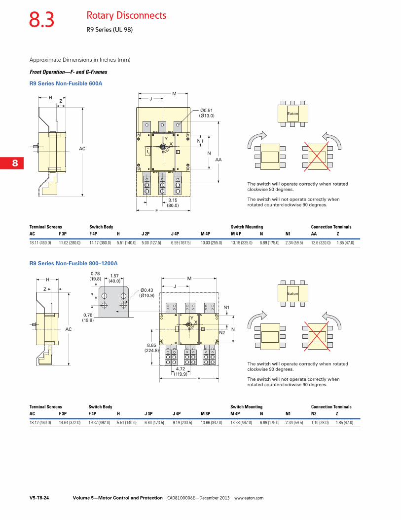
Front Operation—F- and G-Frames
R9 Series Non-Fusible 600A
R9 Series Non-Fusible 800–1200A
HZ
M
Ø0.51(Ø13.0)
J
N1
N
AA
F
X
Y
3.15(80.0)
AC
The switch will operate correctly when rotated
clockwise 90 degrees.
The switch will not operate correctly when
rotated counterclockwise 90 degrees.
Terminal Screens Switch Body Switch Mounting Connection TerminalsAC F 3P F 4P H J 2P J 4P M 4P M 4 P N N1 AA Z
18.11 (460.0) 11.02 (280.0) 14.17 (360.0) 5.51 (140.0) 5.00 (127.5) 6.59 (167.5) 10.03 (255.0) 13.19 (335.0) 6.89 (175.0) 2.34 (59.5) 12.6 (320.0) 1.85 (47.0)
M
J
F
XY
NN2
H
Z
N1
AC
0.78(19.8)
0.78(19.8)
1.57(40.0)
Ø0.43(Ø10.9)
8.85(224.8)
4.72(119.9)
The switch will operate correctly when rotated
clockwise 90 degrees.
The switch will not operate correctly when
rotated counterclockwise 90 degrees.
Terminal Screens Switch Body Switch Mounting Connection TerminalsAC F 3P F 4P H J 3P J 4P M 3P M 4P N N1 N2 Z
18.12 (460.0) 14.64 (372.0) 19.37 (492.0) 5.51 (140.0) 6.83 (173.5) 9.19 (233.5) 13.66 (347.0) 18.38 (467.0) 6.89 (175.0) 2.34 (59.5) 1.10 (28.0) 1.85 (47.0)
Volume 5—Motor Control and Protection CA08100006E—December 2013 www.eaton.com V5-T8-25
8
8
8
8
8
8
8
8
8
8
8
8
8
8
8
8
8
8
8
8
8
8
8
8
8
8
8
8
8
8
8.3Rotary Disconnects
R9 Series (UL 98)
Approximate Dimensions in Inches (mm)
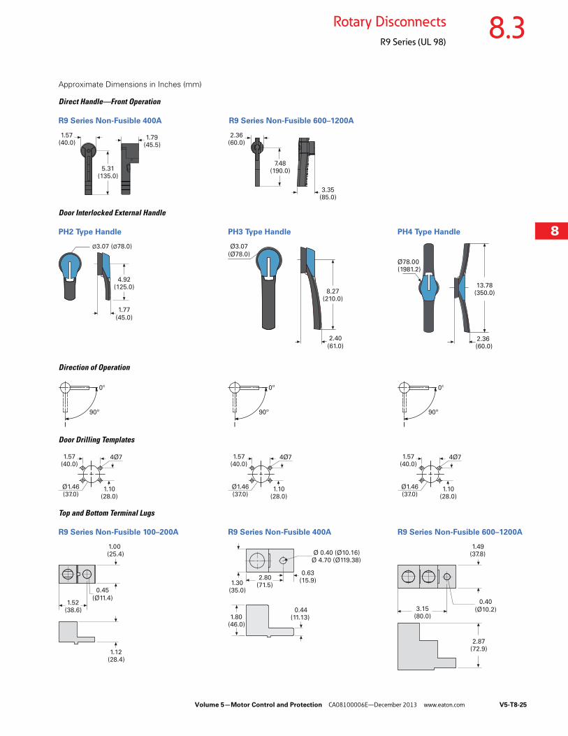
Direct Handle—Front Operation
R9 Series Non-Fusible 400A R9 Series Non-Fusible 600–1200A
Door Interlocked External Handle
PH2 Type Handle PH3 Type Handle PH4 Type Handle
Direction of Operation
Door Drilling Templates
Top and Bottom Terminal Lugs
R9 Series Non-Fusible 100–200A R9 Series Non-Fusible 400A R9 Series Non-Fusible 600–1200A
2.36(60.0)
7.48(190.0)
3.35(85.0)
1.57(40.0)
5.31(135.0)
1.79(45.5)
Ø3.07 (Ø78.0)
4.92(125.0)
1.77
(45.0)
Ø3.07
(Ø78.0)
8.27(210.0)
2.40
(61.0)2.36 (60.0)
13.78(350.0)
Ø78.00 (1981.2)
90º
0º
I
90º
0º
I
90º
0º
I
1.57(40.0)
4Ø7
Ø1.46(37.0)
1.10(28.0)
1.57(40.0)
4Ø7
Ø1.46(37.0)
1.10(28.0)
1.57(40.0)
4Ø7
Ø1.46(37.0)
1.10(28.0)
2.87(72.9)
3.15(80.0)
1.49(37.8)
0.40
(Ø10.2)
2.80(71.5)
Ø 0.40 (Ø10.16)Ø 4.70 (Ø119.38)
1.30(35.0)
1.80(46.0)
0.44(11.13)
0.63(15.9)
1.00 (25.4)
1.52(38.6)
1.12(28.4)
0.45
(Ø11.4)
V5-T8-26 Volume 5—Motor Control and Protection CA08100006E—December 2013 www.eaton.com
8
8
8
8
8
8
8
8
8
8
8
8
8
8
8
8
8
8
8
8
8
8
8
8
8
8
8
8
8
8
8.3 Rotary Disconnects
R9 Series (UL 98)
Fusible 30–800A ContentsDescription Page
Non-Fusible 30–100A Compact . . . . . . . . . . . . . . . V5-T8-11
Non-Fusible 100–1200A . . . . . . . . . . . . . . . . . . . . V5-T8-18
Fusible 30–800AProduct Identification . . . . . . . . . . . . . . . . . . . . V5-T8-27
Product Selection . . . . . . . . . . . . . . . . . . . . . . . V5-T8-28
Accessories. . . . . . . . . . . . . . . . . . . . . . . . . . . . V5-T8-32
Technical Data and Specifications . . . . . . . . . . . V5-T8-37
Dimensions. . . . . . . . . . . . . . . . . . . . . . . . . . . . V5-T8-39
DC Rated Disconnects . . . . . . . . . . . . . . . . . . . . . V5-T8-45
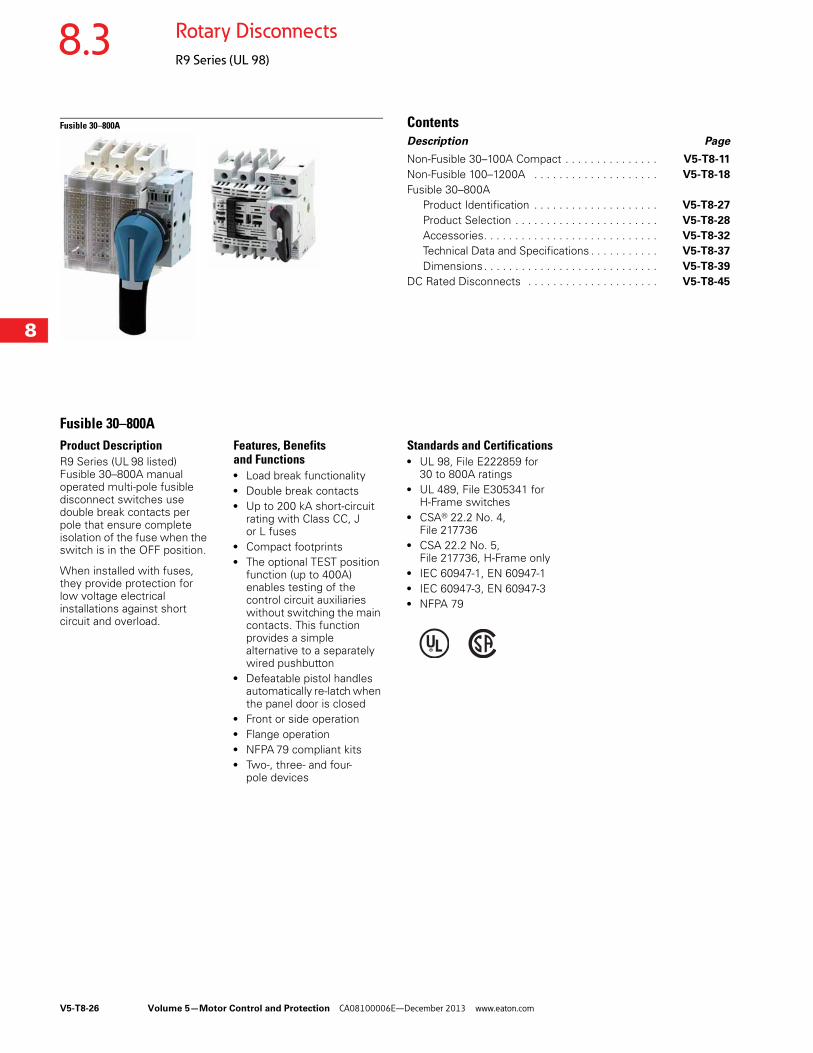
Fusible 30–800AProduct DescriptionR9 Series (UL 98 listed) Fusible 30–800A manual operated multi-pole fusible disconnect switches use double break contacts per pole that ensure complete isolation of the fuse when the switch is in the OFF position.
When installed with fuses, they provide protection for low voltage electrical installations against short circuit and overload.
Features, Benefits and Functions● Load break functionality● Double break contacts● Up to 200 kA short-circuit
rating with Class CC, J or L fuses
● Compact footprints● The optional TEST position
function (up to 400A) enables testing of the control circuit auxiliaries without switching the main contacts. This function provides a simple alternative to a separately wired pushbutton
● Defeatable pistol handles automatically re-latch when the panel door is closed
● Front or side operation● Flange operation● NFPA 79 compliant kits● Two-, three- and four-
pole devices
Standards and Certifications● UL 98, File E222859 for
30 to 800A ratings● UL 489, File E305341 for
H-Frame switches● CSA® 22.2 No. 4,
File 217736● CSA 22.2 No. 5,
File 217736, H-Frame only● IEC 60947-1, EN 60947-1● IEC 60947-3, EN 60947-3● NFPA 79
Volume 5—Motor Control and Protection CA08100006E—December 2013 www.eaton.com V5-T8-27
8
8
8
8
8
8
8
8
8
8
8
8
8
8
8
8
8
8
8
8
8
8
8
8
8
8
8
8
8
8
8.3Rotary Disconnects
R9 Series (UL 98)
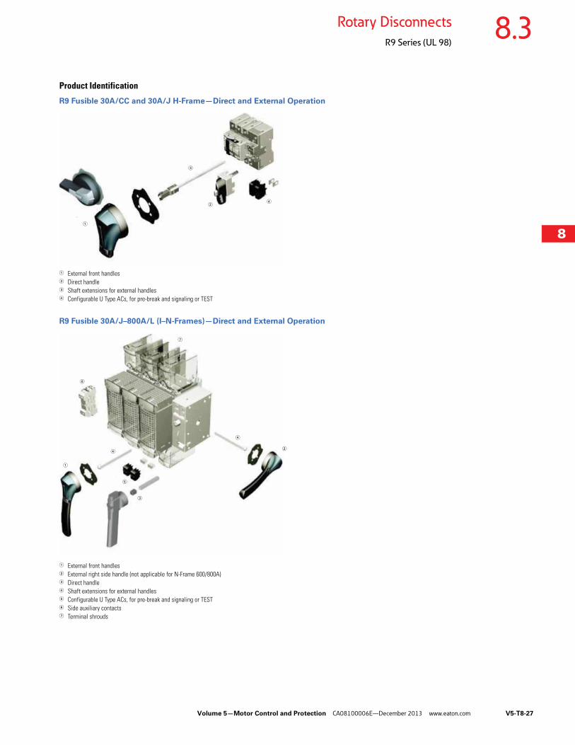
Product Identification
R9 Fusible 30A/CC and 30A/J H-Frame—Direct and External Operation
1 External front handles2 Direct handle3 Shaft extensions for external handles4 Configurable U Type ACs, for pre-break and signaling or TEST
R9 Fusible 30A/J–800A/L (I–N-Frames)—Direct and External Operation
1 External front handles2 External right side handle (not applicable for N-Frame 600/800A)3 Direct handle4 Shaft extensions for external handles5 Configurable U Type ACs, for pre-break and signaling or TEST6 Side auxiliary contacts7 Terminal shrouds
1
2
3
4
1
2
3
4
5
6
7
4
V5-T8-28 Volume 5—Motor Control and Protection CA08100006E—December 2013 www.eaton.com
8
8
8
8
8
8
8
8
8
8
8
8
8
8
8
8
8
8
8
8
8
8
8
8
8
8
8
8
8
8
8.3 Rotary Disconnects
R9 Series (UL 98)
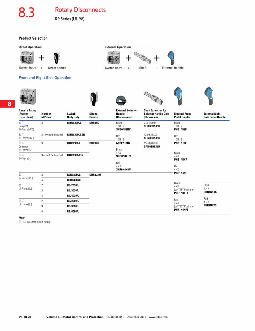
Product Selection
Front and Right Side Operation
Note1 100 kA short-circuit rating.
Ampere Rating(Frame) (Fuse Class)
Number of Poles
Switch Body Only
Direct Handle
External Selector Handle (Choose one)
Shaft Extension for Selector Handle Only (Choose one)
External Front Pistol Handle
External Right Side Pistol Handle
30 1Compact (H-Frame) (CC)
3 R4H3030FCC DHR9HC Black1,3R,12SHB0N12HV
Red1,3R,12SHR0N12HV
Black4,4XSHB0N4XHV
Red4,4XSHR0N4XHV
7.90 (200.0)SF200SH5X5H
Black1,3R,12PHB1N12F
Red1,3R,12PHR1N12F
Black4,4XPHB1N4XF
Red4,4XPHR1N4XF
Black4,4X(w/ TEST Position)PHB1N4XFT
Red4,4X(w/ TEST Position)PHR1N4XFT
—
30 1(H-Frame) (CC)
3 + switched neutral R4H3030FCCSN 12.60 320.0)SF320SH5X5H
30 1Compact (H-Frame) (J)
3 R4H3030FJ DHR9HJ 15.70 (400.0)SF400SH5X5H
30 1(H-Frame) (J)
3 + switched neutral R4H3030FJSN
30 (I-Frame) (CC)
3 R9I3030FCC DHR9J2M — —
4 R9I4030FCC
30(J-Frame) (J)
2 R9J2030FJ Black4, 4XPHB1N4XS
Red4, 4XPHR1N4XS
3 R9J3030FJ
4 R9J4030FJ
60 1(J-Frame) (J)
2 R9J2060FJ
3 R9J3060FJ
4 R9J4060FJ
+ + +Switch body Direct handle Switch body Shaft External handle+ + +
Direct Operation External Operation
Volume 5—Motor Control and Protection CA08100006E—December 2013 www.eaton.com V5-T8-29
8
8
8
8
8
8
8
8
8
8
8
8
8
8
8
8
8
8
8
8
8
8
8
8
8
8
8
8
8
8
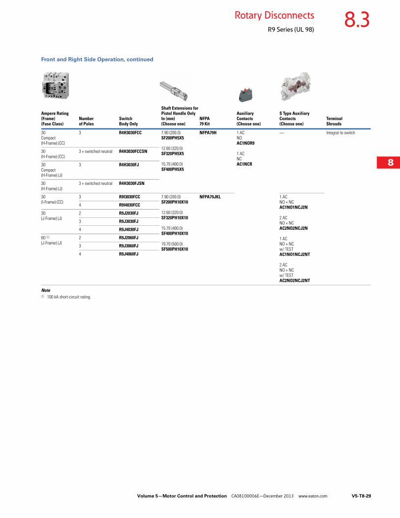
8.3Rotary Disconnects
R9 Series (UL 98)
Front and Right Side Operation, continued
Note1 100 kA short-circuit rating.
Ampere Rating(Frame) (Fuse Class)
Number of Poles
Switch Body Only
Shaft Extensions for Pistol Handle OnlyIn (mm)(Choose one)
NFPA 79 Kit
Auxiliary Contacts (Choose one)
S Type Auxiliary Contacts (Choose one)
Terminal Shrouds
30 Compact(H-Frame) (CC)
3 R4H3030FCC 7.90 (200.0)SF200PH5X5
12.60 (320.0)SF320PH5X5
15.70 (400.0)SF400PH5X5
NFPA79H 1 ACNOAC1NOR9
1 ACNCAC1NCR
— Integral to switch
30 (H-Frame) (CC)
3 + switched neutral R4H3030FCCSN
30 Compact(H-Frame) (J)
3 R4H3030FJ
30 (H-Frame) (J)
3 + switched neutral R4H3030FJSN
30 (I-Frame) (CC)
3 R9I3030FCC 7.90 (200.0)SF200PH10X10
12.60 (320.0)SF320PH10X10
15.70 (400.0)SF400PH10X10
19.70 (500.0)SF500PH10X10
NFPA79JKL 1 ACNO + NCAC1NO1NCJ2N
2 ACNO + NCAC2NO2NCJ2N
1 ACNO + NCw/ TESTAC1NO1NCJ2NT
2 ACNO + NCw/ TESTAC2NO2NCJ2NT
4 R9I4030FCC
30 (J-Frame) (J)
2 R9J2030FJ
3 R9J3030FJ
4 R9J4030FJ
60 1(J-Frame) (J)
2 R9J2060FJ
3 R9J3060FJ
4 R9J4060FJ
V5-T8-30 Volume 5—Motor Control and Protection CA08100006E—December 2013 www.eaton.com
8
8
8
8
8
8
8
8
8
8
8
8
8
8
8
8
8
8
8
8
8
8
8
8
8
8
8
8
8
8
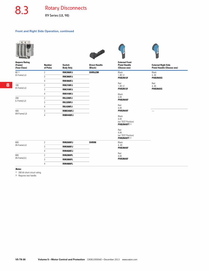
8.3 Rotary Disconnects
R9 Series (UL 98)
Front and Right Side Operation, continued
Notes1 200 kA short-circuit rating.2 Requires test handle.
Ampere Rating (Frame) (Fuse Class)
Number of Poles
Switch Body Only
Direct Handle (Black)
External Front Pistol Handle (Choose one)
External Right Side Pistol Handle (Choose one)
60 1(K-Frame) (J)
2 R9K2060FJ DHR9J2M Black1,3R,12PHB2N12F
Red1,3R,12PHR2N12F
Black4,4XPHB2N4XF
Red4,4XPHR2N4XF
Black4,4X(w/ TEST Position)PHB2N4XFT 2
Red4,4X(w/ TEST Position)PHR2N4XFT 2
Black4, 4XPHB2N4XS
Red4, 4XPHR2N4XS
3 R9K3060FJ
4 R9K4060FJ
100(K-Frame) (J)
2 R9K2100FJ
3 R9K3100FJ
4 R9K4100FJ
200(L-Frame) (J)
2 R9L2200FJ
3 R9L3200FJ
4 R9L4200FJ
400(M-Frame) (J)
3 R9M3400FJ —
4 R9M4400FJ
600(N-Frame) (J)
2 R9N2600FJ DHR9N Black4, 4XPHB3N4XF
Red4,4XPHR3N4XF
3 R9N3600FJ
4 R9N4600FJ
800(N-Frame) (L)
2 R9N2800FL
3 R9N3800FL
4 R9N4800FL
Volume 5—Motor Control and Protection CA08100006E—December 2013 www.eaton.com V5-T8-31
8
8
8
8
8
8
8
8
8
8
8
8
8
8
8
8
8
8
8
8
8
8
8
8
8
8
8
8
8
8
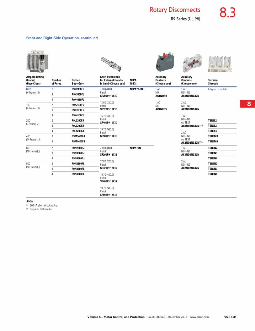
8.3Rotary Disconnects
R9 Series (UL 98)
Front and Right Side Operation, continued
Notes1 200 kA short-circuit rating.2 Requires test handle.
Ampere Rating(Frame) (Fuse Class)
Number of Poles
Switch Body Only
Shaft Extensions for External Handle In (mm) (Choose one)
NFPA 79 Kit
Auxiliary Contacts (Choose one)
Auxiliary Contacts (Choose one)
Terminal Shrouds
60 1(K-Frame) (J)
2 R9K2060FJ 7.90 (200.0)PistolSF200PH10X10
12.60 (320.0)PistolSF320PH10X10
15.70 (400.0)PistolSF400PH10X10
19.70 (500.0)PistolSF500PH10X10
NFPA79JKL 1 ACNOAC1NOR9
1 ACNCAC1NCR9
1 ACNO + NCAC1NO1NCJ2N
2 ACNO + NCAC2NO2NCJ2N
1 ACNO + NCw/ TESTAC1NO1NCJ2NT 2
2 ACNO + NCw/ TESTAC2NO2NCJ2NT 2
Integral to switch
3 R9K3060FJ
4 R9K4060FJ
100(K-Frame) (J)
2 R9K2100FJ
3 R9K3100FJ
4 R9K4100FJ
200(L-Frame) (J)
2 R9L2200FJ TSR9L2
3 R9L3200FJ TSR9L3
4 R9L4200FJ TSR9L4
400(M-Frame) (J)
3 R9M3400FJ TSR9M3
4 R9M4400FJ TSR9M4
600(N-Frame) (J)
2 R9N2600FJ 7.90 (200.0)PistolSF200PH12X12
12.60 (320.0)PistolSF320PH12X12
15.70 (400.0)PistolSF400PH12X12
19.70 (500.0)PistolSF500PH12X12
NFPA79N 1 ACNO + NCAC1NO1NCJ2N
2 ACNO + NCAC2NO2NCJ2N
TSR9N2
3 R9N3600FJ TSR9N3
4 R9N4600FJ TSR9N4
800(N-Frame) (L)
2 R9N2800FL TSR9N2
3 R9N3800FL TSR9N3
4 R9N4800FL TSR9N4
V5-T8-32 Volume 5—Motor Control and Protection CA08100006E—December 2013 www.eaton.com
8
8
8
8
8
8
8
8
8
8
8
8
8
8
8
8
8
8
8
8
8
8
8
8
8
8
8
8
8
8
8.3 Rotary Disconnects
R9 Series (UL 98)
Accessories
NFPA 79 Compliant
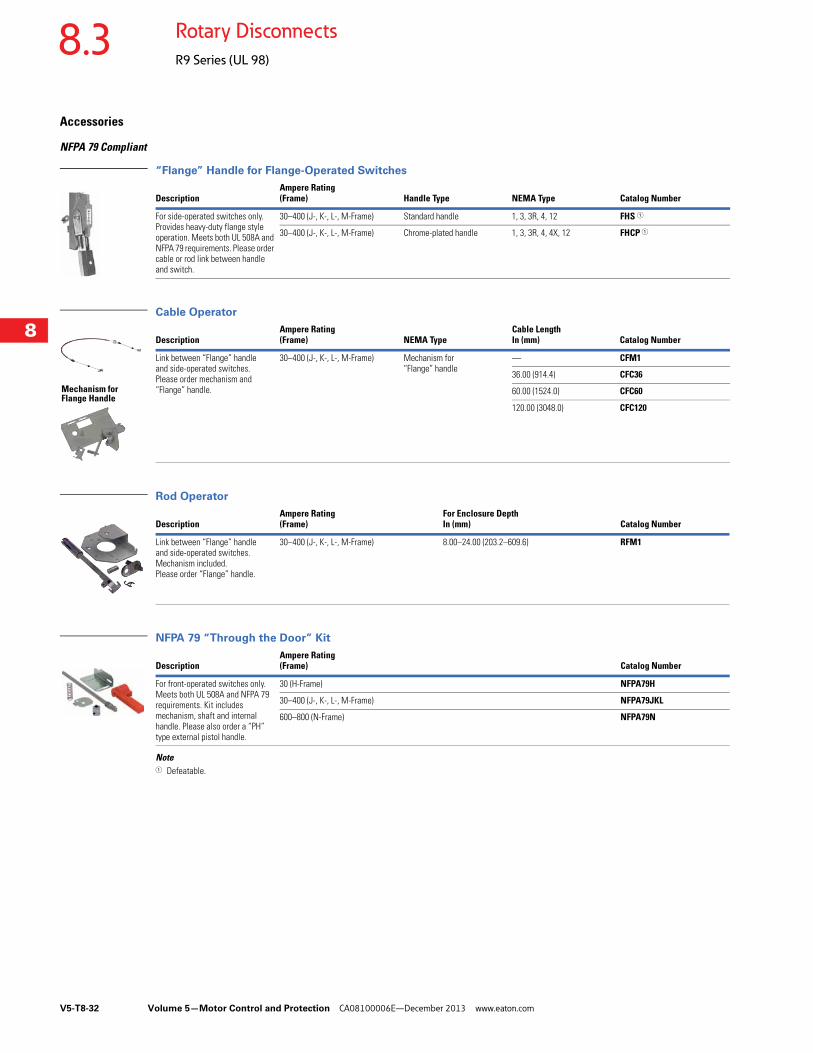
“Flange” Handle for Flange-Operated Switches
Cable Operator
Rod Operator
NFPA 79 “Through the Door” Kit
Note1 Defeatable.
DescriptionAmpere Rating (Frame) Handle Type NEMA Type Catalog Number
For side-operated switches only. Provides heavy-duty flange style operation. Meets both UL 508A and NFPA 79 requirements. Please order cable or rod link between handle and switch.
30–400 (J-, K-, L-, M-Frame) Standard handle 1, 3, 3R, 4, 12 FHS 1
30–400 (J-, K-, L-, M-Frame) Chrome-plated handle 1, 3, 3R, 4, 4X, 12 FHCP 1
DescriptionAmpere Rating(Frame) NEMA Type
Cable LengthIn (mm) Catalog Number
Link between “Flange” handle and side-operated switches. Please order mechanism and “Flange” handle.
30–400 (J-, K-, L-, M-Frame) Mechanism for “Flange” handle
— CFM1
36.00 (914.4) CFC36
60.00 (1524.0) CFC60
120.00 (3048.0) CFC120
DescriptionAmpere Rating(Frame)
For Enclosure Depth In (mm) Catalog Number
Link between “Flange” handle and side-operated switches. Mechanism included.Please order “Flange” handle.
30–400 (J-, K-, L-, M-Frame) 8.00–24.00 (203.2–609.6) RFM1
DescriptionAmpere Rating (Frame) Catalog Number
For front-operated switches only. Meets both UL 508A and NFPA 79 requirements. Kit includes mechanism, shaft and internal handle. Please also order a “PH”type external pistol handle.
30 (H-Frame) NFPA79H
30–400 (J-, K-, L-, M-Frame) NFPA79JKL
600–800 (N-Frame) NFPA79N
Mechanism for Flange Handle
Volume 5—Motor Control and Protection CA08100006E—December 2013 www.eaton.com V5-T8-33
8
8
8
8
8
8
8
8
8
8
8
8
8
8
8
8
8
8
8
8
8
8
8
8
8
8
8
8
8
8
8.3Rotary Disconnects
R9 Series (UL 98)
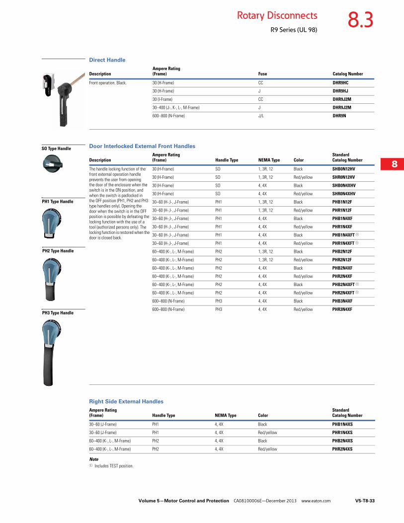
Direct Handle
Door Interlocked External Front Handles
Right Side External Handles
Note1 Includes TEST position.
DescriptionAmpere Rating (Frame) Fuse Catalog Number
Front operation. Black. 30 (H-Frame) CC DHR9HC
30 (H-Frame) J DHR9HJ
30 (I-Frame) CC DHR9J2M
30–400 (J-, K-, L-, M-Frame) J DHR9J2M
600–800 (N-Frame) J/L DHR9N
DescriptionAmpere Rating (Frame) Handle Type NEMA Type Color
Standard Catalog Number
The handle locking function of the front external operation handle prevents the user from opening the door of the enclosure when the switch is in the ON position, and when the switch is padlocked in the OFF position (PH1, PH2 and PH3 type handles only). Opening the door when the switch is in the OFF position is possible by defeating the locking function with the use of a tool (authorized persons only). The locking function is restored when the door is closed back.
30 (H-Frame) SO 1, 3R, 12 Black SHB0N12HV
30 (H-Frame) SO 1, 3R, 12 Red/yellow SHR0N12HV
30 (H-Frame) SO 4, 4X Black SHB0N4XHV
30 (H-Frame) SO 4, 4X Red/yellow SHR0N4XHV
30–60 (H-,I-, J-Frame) PH1 1, 3R, 12 Black PHB1N12F
30–60 (H-,I-, J-Frame) PH1 1, 3R, 12 Red/yellow PHR1N12F
30–60 (H-,I-, J-Frame) PH1 4, 4X Black PHB1N4XF
30–60 (H-,I-, J-Frame) PH1 4, 4X Red/yellow PHR1N4XF
30–60 (H-,I-, J-Frame) PH1 4, 4X Black PHB1N4XFT 1
30–60 (H-,I-, J-Frame) PH1 4, 4X Red/yellow PHR1N4XFT 1
60–400 (K-, L-, M-Frame) PH2 1, 3R, 12 Black PHB2N12F
60–400 (K-, L-, M-Frame) PH2 1, 3R, 12 Red/yellow PHR2N12F
60–400 (K-, L-, M-Frame) PH2 4, 4X Black PHB2N4XF
60–400 (K-, L-, M-Frame) PH2 4, 4X Red/yellow PHR2N4XF
60–400 (K-, L-, M-Frame) PH2 4, 4X Black PHB2N4XFT 1
60–400 (K-, L-, M-Frame) PH2 4, 4X Red/yellow PHR2N4XFT 1
600–800 (N-Frame) PH3 4, 4X Black PHB3N4XF
600–800 (N-Frame) PH3 4, 4X Red/yellow PHR3N4XF
Ampere Rating (Frame) Handle Type NEMA Type Color
StandardCatalog Number
30–60 (J-Frame) PH1 4, 4X Black PHB1N4XS
30–60 (J-Frame) PH1 4, 4X Red/yellow PHR1N4XS
60–400 (K-, L-, M-Frame) PH2 4, 4X Black PHB2N4XS
60–400 (K-, L-, M-Frame) PH2 4, 4X Red/yellow PHR2N4XS
SO Type Handle
PH1 Type Handle
PH2 Type Handle
PH3 Type Handle
V5-T8-34 Volume 5—Motor Control and Protection CA08100006E—December 2013 www.eaton.com
8
8
8
8
8
8
8
8
8
8
8
8
8
8
8
8
8
8
8
8
8
8
8
8
8
8
8
8
8
8
8.3 Rotary Disconnects
R9 Series (UL 98)
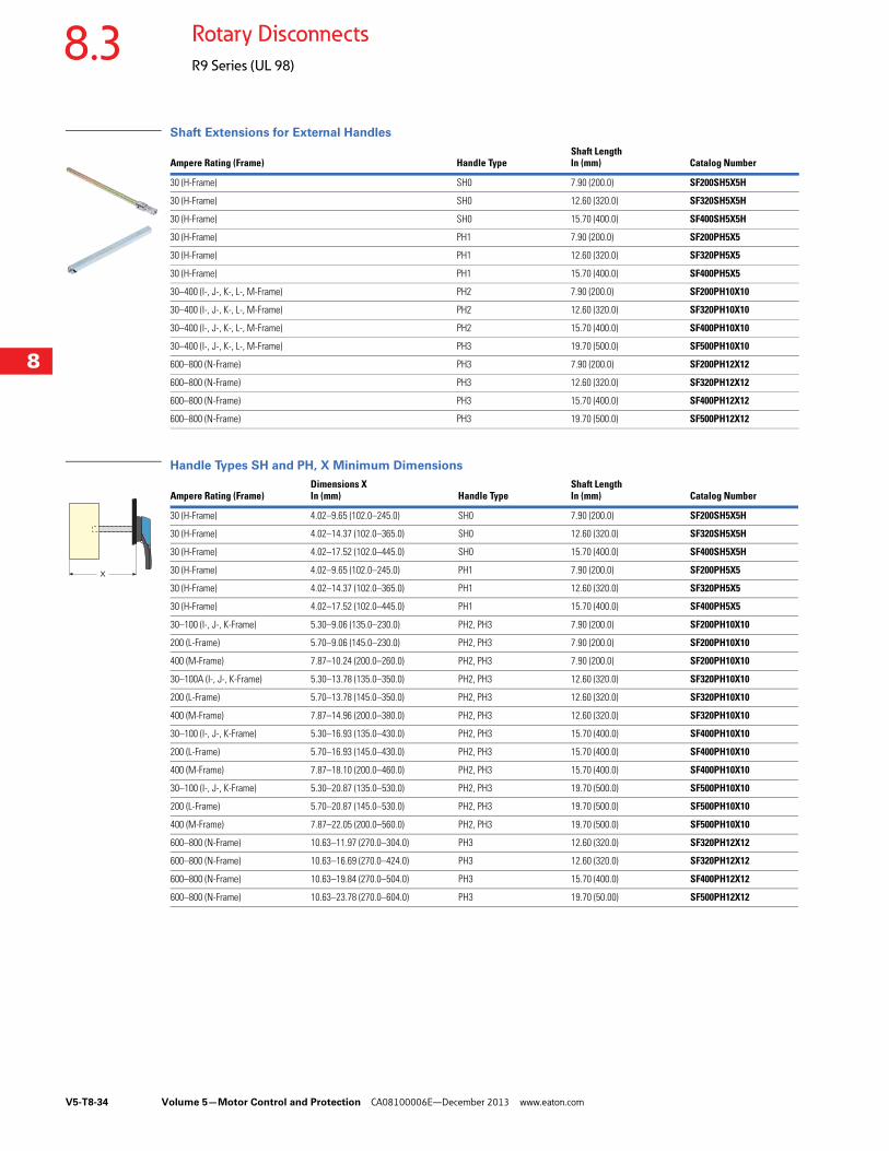
Shaft Extensions for External Handles
Handle Types SH and PH, X Minimum Dimensions
Ampere Rating (Frame) Handle TypeShaft Length In (mm) Catalog Number
30 (H-Frame) SH0 7.90 (200.0) SF200SH5X5H
30 (H-Frame) SH0 12.60 (320.0) SF320SH5X5H
30 (H-Frame) SH0 15.70 (400.0) SF400SH5X5H
30 (H-Frame) PH1 7.90 (200.0) SF200PH5X5
30 (H-Frame) PH1 12.60 (320.0) SF320PH5X5
30 (H-Frame) PH1 15.70 (400.0) SF400PH5X5
30–400 (I-, J-, K-, L-, M-Frame) PH2 7.90 (200.0) SF200PH10X10
30–400 (I-, J-, K-, L-, M-Frame) PH2 12.60 (320.0) SF320PH10X10
30–400 (I-, J-, K-, L-, M-Frame) PH2 15.70 (400.0) SF400PH10X10
30–400 (I-, J-, K-, L-, M-Frame) PH3 19.70 (500.0) SF500PH10X10
600–800 (N-Frame) PH3 7.90 (200.0) SF200PH12X12
600–800 (N-Frame) PH3 12.60 (320.0) SF320PH12X12
600–800 (N-Frame) PH3 15.70 (400.0) SF400PH12X12
600–800 (N-Frame) PH3 19.70 (500.0) SF500PH12X12
Ampere Rating (Frame)Dimensions XIn (mm) Handle Type
Shaft LengthIn (mm) Catalog Number
30 (H-Frame) 4.02–9.65 (102.0–245.0) SH0 7.90 (200.0) SF200SH5X5H
30 (H-Frame) 4.02–14.37 (102.0–365.0) SH0 12.60 (320.0) SF320SH5X5H
30 (H-Frame) 4.02–17.52 (102.0–445.0) SH0 15.70 (400.0) SF400SH5X5H
30 (H-Frame) 4.02–9.65 (102.0–245.0) PH1 7.90 (200.0) SF200PH5X5
30 (H-Frame) 4.02–14.37 (102.0–365.0) PH1 12.60 (320.0) SF320PH5X5
30 (H-Frame) 4.02–17.52 (102.0–445.0) PH1 15.70 (400.0) SF400PH5X5
30–100 (I-, J-, K-Frame) 5.30–9.06 (135.0–230.0) PH2, PH3 7.90 (200.0) SF200PH10X10
200 (L-Frame) 5.70–9.06 (145.0–230.0) PH2, PH3 7.90 (200.0) SF200PH10X10
400 (M-Frame) 7.87–10.24 (200.0–260.0) PH2, PH3 7.90 (200.0) SF200PH10X10
30–100A (I-, J-, K-Frame) 5.30–13.78 (135.0–350.0) PH2, PH3 12.60 (320.0) SF320PH10X10
200 (L-Frame) 5.70–13.78 (145.0–350.0) PH2, PH3 12.60 (320.0) SF320PH10X10
400 (M-Frame) 7.87–14.96 (200.0–380.0) PH2, PH3 12.60 (320.0) SF320PH10X10
30–100 (I-, J-, K-Frame) 5.30–16.93 (135.0–430.0) PH2, PH3 15.70 (400.0) SF400PH10X10
200 (L-Frame) 5.70–16.93 (145.0–430.0) PH2, PH3 15.70 (400.0) SF400PH10X10
400 (M-Frame) 7.87–18.10 (200.0–460.0) PH2, PH3 15.70 (400.0) SF400PH10X10
30–100 (I-, J-, K-Frame) 5.30–20.87 (135.0–530.0) PH2, PH3 19.70 (500.0) SF500PH10X10
200 (L-Frame) 5.70–20.87 (145.0–530.0) PH2, PH3 19.70 (500.0) SF500PH10X10
400 (M-Frame) 7.87–22.05 (200.0–560.0) PH2, PH3 19.70 (500.0) SF500PH10X10
600–800 (N-Frame) 10.63–11.97 (270.0–304.0) PH3 12.60 (320.0) SF320PH12X12
600–800 (N-Frame) 10.63–16.69 (270.0–424.0) PH3 12.60 (320.0) SF320PH12X12
600–800 (N-Frame) 10.63–19.84 (270.0–504.0) PH3 15.70 (400.0) SF400PH12X12
600–800 (N-Frame) 10.63–23.78 (270.0–604.0) PH3 19.70 (50.00) SF500PH12X12
X

Volume 5—Motor Control and Protection CA08100006E—December 2013 www.eaton.com V5-T8-35
8
8
8
8
8
8
8
8
8
8
8
8
8
8
8
8
8
8
8
8
8
8
8
8
8
8
8
8
8
8
8.3Rotary Disconnects
R9 Series (UL 98)
Auxiliary Contacts—NO + NC 1
Auxiliary Contacts—NO or NC 3
Characteristics for Pre-Break Auxiliary Contacts
Terminal Shrouds
Notes1 Same-make/same-break auxiliary contacts.2 Auxiliary contacts without “Test” cannot be used on I–M-Frame switches.3 Early-break/same-make auxiliary contacts.4 For replacement only. Both line and load side terminal shrouds are included with 400A switch.
Operating Current Ie (Amperes)
DescriptionAmpere Rating (Frame)
Number of ACs Nominal Current (Amperes)
Catalog Number
For the R9 Series Fusible 30–800A, indication of the O and I positions by 1 to 4 NO + NC auxiliary contacts.Electrical principle:Cabling by terminal cage with #16 AWG maximum.High electrical characteristics:A600/D600
600–800 (N-Frame) 1NO + 1NC 10 AC1NO1NCJ2N 2
600–800 (N-Frame) 2NO + 2NC 10 AC2NO2NCJ2N 2
30–400 (I–M-Frame) 1NO + 1NC (w/ TEST) 10 AC1NO1NCJ2NT
30–400 (I–M-Frame) 2NO + 2NC (w/ TEST) 10 AC2NO2NCJ2NT
Description Ampere Rating (Frame) Number of ACs Catalog Number
The different functions (pre-break, 0 and 1 indication, TEST feature) are easily configurable with pegs (one or two pegs per position). Two superposed auxiliary contacts maximum.For 30A/CC (H-Frame), maximum of four ACs.For 30A/J (H-Frame), maximum of two ACs.For 30 to 100A/J (I, J and K-Frame), maximum of four ACs.For 200 to 600A/J (L and M-Frame), maximum of eight ACs.Cabling to the control circuit by terminals with a maximum section of 2 x 2.5 mm2.Electrical characteristics: A300
NO Auxiliary Contact
30–600 (H–M-Frame) 1 AC1NOR9
NC Auxiliary Contact
30–600 (H–M-Frame) 1 AC1NCR9
Operating Current Ie (Amperes)
Ampere Rating Contact TypeNominal Current Amperes 250 Vac AC-13 400 Vac AC-13 24 Vdc DC-13 48 Vdc DC-13
30–800 NO + NC 10 6 4 5 3
Description Ampere Rating (Frame) Number of Poles Catalog Number
Line or load side protection against direct contact with terminals or the connection parts
30–100 (H-, I-, J-, K-Frame) 2/3/4 Integral to switch
200 (L-Frame) 2 TSR9L2
200 (L-Frame) 3 TSR9L3
200 (L-Frame) 4 TSR9L3
400 (M-Frame) 2 TSR9M2 4
400 (M-Frame) 3 TSR9M3 4
400 (M-Frame) 4 TSR9M4 4
600–800 (N-Frame) 2 TSR9N2
600–800 (N-Frame) 3 TSR9N3
600–800 (N-Frame) 4 TSR9N4
Terminal Shrouds
V5-T8-36 Volume 5—Motor Control and Protection CA08100006E—December 2013 www.eaton.com
8
8
8
8
8
8
8
8
8
8
8
8
8
8
8
8
8
8
8
8
8
8
8
8
8
8
8
8
8
8
8.3 Rotary Disconnects
R9 Series (UL 98)
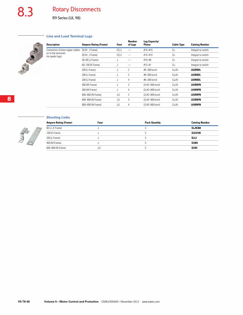
Line and Load Terminal Lugs
Shorting Links
Description Ampere Rating (Frame) FuseNumber of Lugs
Lug Capacity/Phase Cable Type Catalog Number
Connection of bare copper cables on to the terminals (no spade lugs).
30 (H-, I-Frame) CC/J — #14–#10 Cu Integral to switch
30 (H-, I-Frame) CC/J — #14–#10 Cu Integral to switch
30–60 (J-Frame) J — #10–#6 Cu Integral to switch
60–100 (K-Frame) J — #12–#1 Cu Integral to switch
200 (L-Frame) J 2 #6–300 kcmil Cu/Al LK2R9DL
200 (L-Frame) J 3 #6–300 kcmil Cu/Al LK3R9DL
200 (L-Frame) J 4 #6–300 kcmil Cu/Al LK4R9DL
400 (M-Frame) J 3 (2) #2–600 kcmil Cu/Al LK3R9FN
400 (M-Frame) J 4 (2) #2–600 kcmil Cu/Al LK4R9FN
600–800 (N-Frame) J/L 2 (2) #2–600 kcmil Cu/Al LK2R9FN
600–800 (N-Frame) J/L 3 (2) #2–600 kcmil Cu/Al LK3R9FN
600–800 (N-Frame) J/L 4 (2) #2–600 kcmil Cu/Al LK4R9FN
Ampere Rating (Frame) Fuse Pack Quantity Catalog Number
60 (J-,K-Frame) J 3 SLJK360
100 (K-Frame) J 3 SLK3100
200 (L-Frame) J 3 SLL3
400 (M-Frame) J 3 SLM3
600–800 (N-Frame) J/L 3 SLN3
Volume 5—Motor Control and Protection CA08100006E—December 2013 www.eaton.com V5-T8-37
8
8
8
8
8
8
8
8
8
8
8
8
8
8
8
8
8
8
8
8
8
8
8
8
8
8
8
8
8
8
8.3Rotary Disconnects
R9 Series (UL 98)
Technical Data and Specifications
UL and CSA Characteristics
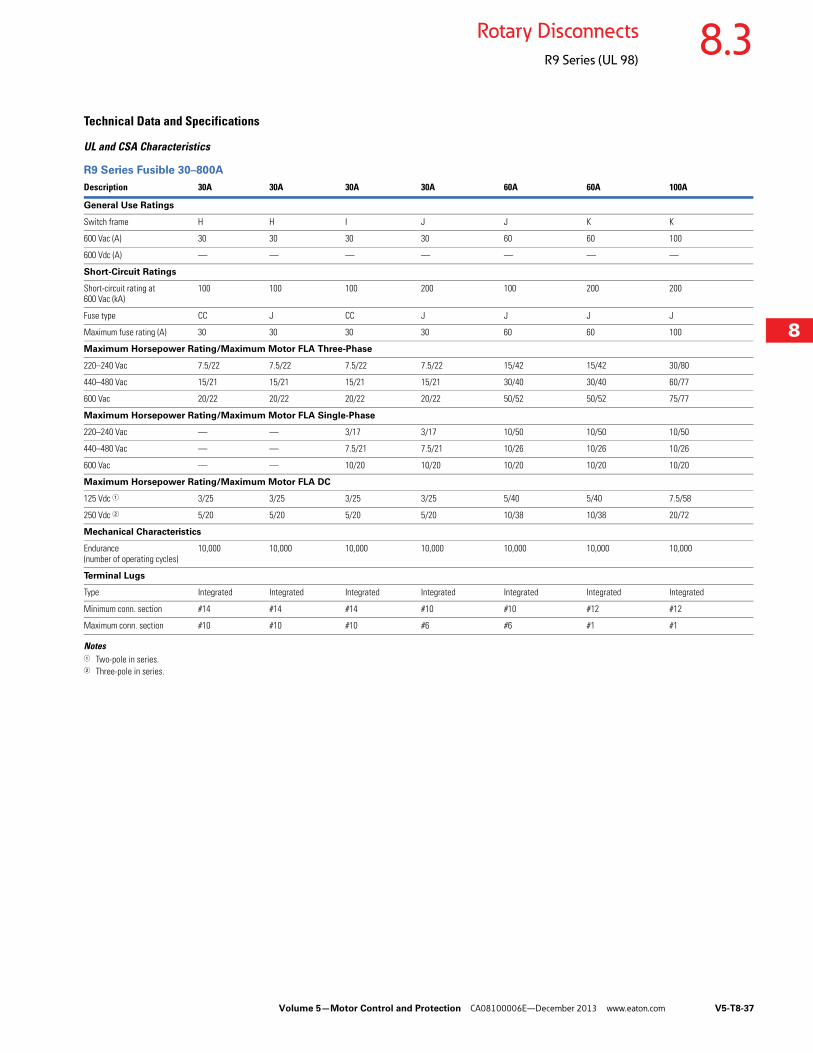
R9 Series Fusible 30–800A
Notes1 Two-pole in series.2 Three-pole in series.
Description 30A 30A 30A 30A 60A 60A 100A
General Use Ratings
Switch frame H H I J J K K
600 Vac (A) 30 30 30 30 60 60 100
600 Vdc (A) — — — — — — —
Short-Circuit Ratings
Short-circuit rating at 600 Vac (kA)
100 100 100 200 100 200 200
Fuse type CC J CC J J J J
Maximum fuse rating (A) 30 30 30 30 60 60 100
Maximum Horsepower Rating/Maximum Motor FLA Three-Phase
220–240 Vac 7.5/22 7.5/22 7.5/22 7.5/22 15/42 15/42 30/80
440–480 Vac 15/21 15/21 15/21 15/21 30/40 30/40 60/77
600 Vac 20/22 20/22 20/22 20/22 50/52 50/52 75/77
Maximum Horsepower Rating/Maximum Motor FLA Single-Phase
220–240 Vac — — 3/17 3/17 10/50 10/50 10/50
440–480 Vac — — 7.5/21 7.5/21 10/26 10/26 10/26
600 Vac — — 10/20 10/20 10/20 10/20 10/20
Maximum Horsepower Rating/Maximum Motor FLA DC
125 Vdc 1 3/25 3/25 3/25 3/25 5/40 5/40 7.5/58
250 Vdc 2 5/20 5/20 5/20 5/20 10/38 10/38 20/72
Mechanical Characteristics
Endurance (number of operating cycles)
10,000 10,000 10,000 10,000 10,000 10,000 10,000
Terminal Lugs
Type Integrated Integrated Integrated Integrated Integrated Integrated Integrated
Minimum conn. section #14 #14 #14 #10 #10 #12 #12
Maximum conn. section #10 #10 #10 #6 #6 #1 #1

V5-T8-38 Volume 5—Motor Control and Protection CA08100006E—December 2013 www.eaton.com
8
8
8
8
8
8
8
8
8
8
8
8
8
8
8
8
8
8
8
8
8
8
8
8
8
8
8
8
8
8
8.3 Rotary Disconnects
R9 Series (UL 98)
R9 Series Fusible 30–800A, continued
Notes1 Two-pole in series.2 Three-pole in series.
Description 200A 400A 600A 800A
General Use Ratings
Switch Frame L M N N
600 Vac (A) 200 400 600 800
600 Vdc (A) — — 600 2 800 2
Short-Circuit Ratings
Short-circuit rating at 600 Vac (kA) 200 200 200 200
Fuse type J J J L
Maximum fuse rating (A) 200 400 600 800
Maximum Horsepower Rating/Maximum Motor FLA Single-Phase
220–240 Vac — — — —
440–480 Vac — — — —
600 Vac — — — —
Maximum Horsepower Rating/Maximum Motor FLA Three-Phase
220–240 Vac 60/154 125/312 200/480 200/480
440–480 Vac 125/156 250/302 500/590 500/590
600 Vac 150/144 350/336 500/472 500/472
Maximum Horsepower Rating/Maximum Motor FLA DC
125 Vdc 1 — 20/148 — —
250 Vdc 2 — 50/173 2 — —
Mechanical Characteristics
Endurance (number of operating cycles)
8000 6000 5000 5000
Terminal Lugs
Type Option Option Option Option
Minimum conn. section #6 #2 2x#2 2x#2
Maximum conn. section 3/0 300 kcmil 2 x 600 kcmil 2 x 600 kcmil
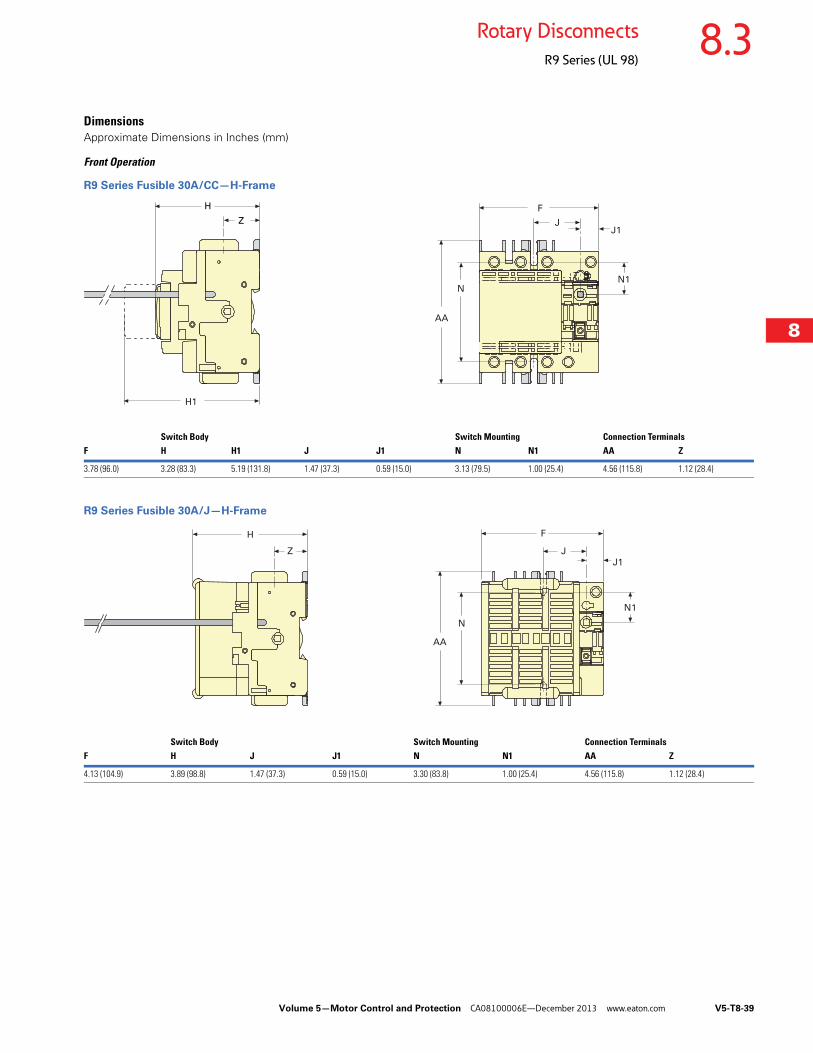
Volume 5—Motor Control and Protection CA08100006E—December 2013 www.eaton.com V5-T8-39
8
8
8
8
8
8
8
8
8
8
8
8
8
8
8
8
8
8
8
8
8
8
8
8
8
8
8
8
8
8
8.3Rotary Disconnects
R9 Series (UL 98)
DimensionsApproximate Dimensions in Inches (mm)
Front Operation
R9 Series Fusible 30A/CC—H-Frame
R9 Series Fusible 30A/J—H-Frame
H
Z
H1
AA
NN1
F
JJ1
Switch Body Switch Mounting Connection TerminalsF H H1 J J1 N N1 AA Z
3.78 (96.0) 3.28 (83.3) 5.19 (131.8) 1.47 (37.3) 0.59 (15.0) 3.13 (79.5) 1.00 (25.4) 4.56 (115.8) 1.12 (28.4)
H
Z
F
J
J1
AA
N
N1
Switch Body Switch Mounting Connection TerminalsF H J J1 N N1 AA Z
4.13 (104.9) 3.89 (98.8) 1.47 (37.3) 0.59 (15.0) 3.30 (83.8) 1.00 (25.4) 4.56 (115.8) 1.12 (28.4)
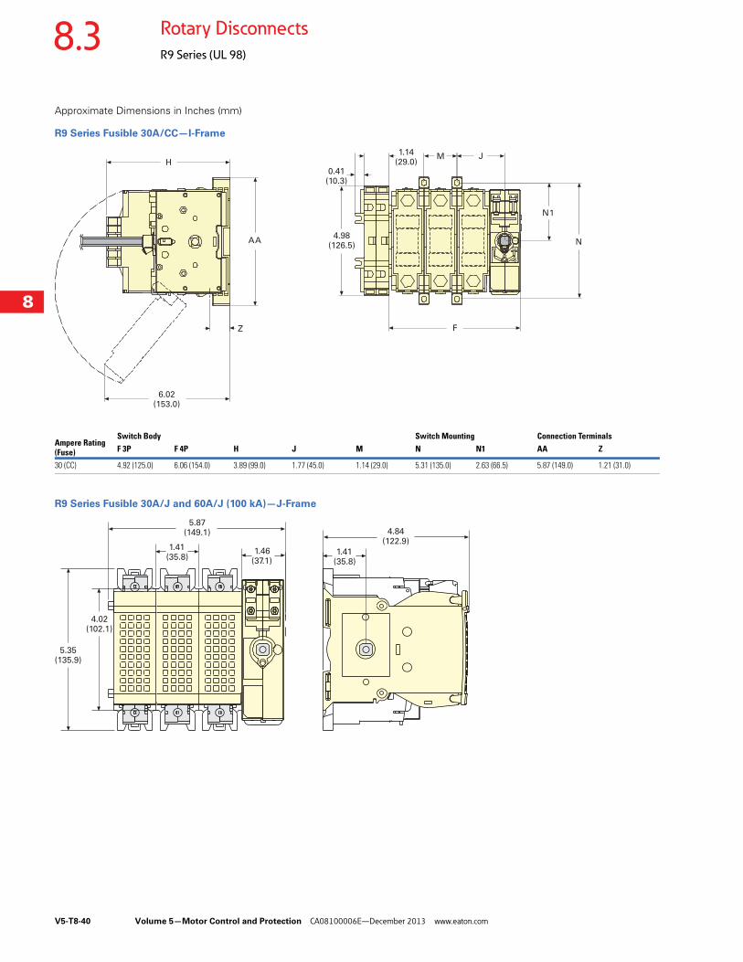
V5-T8-40 Volume 5—Motor Control and Protection CA08100006E—December 2013 www.eaton.com
8
8
8
8
8
8
8
8
8
8
8
8
8
8
8
8
8
8
8
8
8
8
8
8
8
8
8
8
8
8
8.3 Rotary Disconnects
R9 Series (UL 98)
Approximate Dimensions in Inches (mm)
R9 Series Fusible 30A/CC—I-Frame
R9 Series Fusible 30A/J and 60A/J (100 kA)—J-Frame
M J
F
N1
N
H
AA
Z
1.14(29.0)
0.41(10.3)
4.98(126.5)
6.02(153.0)
Ampere Rating (Fuse)
Switch Body Switch Mounting Connection TerminalsF 3P F 4P H J M N N1 AA Z
30 (CC) 4.92 (125.0) 6.06 (154.0) 3.89 (99.0) 1.77 (45.0) 1.14 (29.0) 5.31 (135.0) 2.63 (66.5) 5.87 (149.0) 1.21 (31.0)
5.35(135.9)
5.87(149.1)
1.41(35.8)
1.46(37.1)
4.84(122.9)
1.41(35.8)
4.02(102.1)
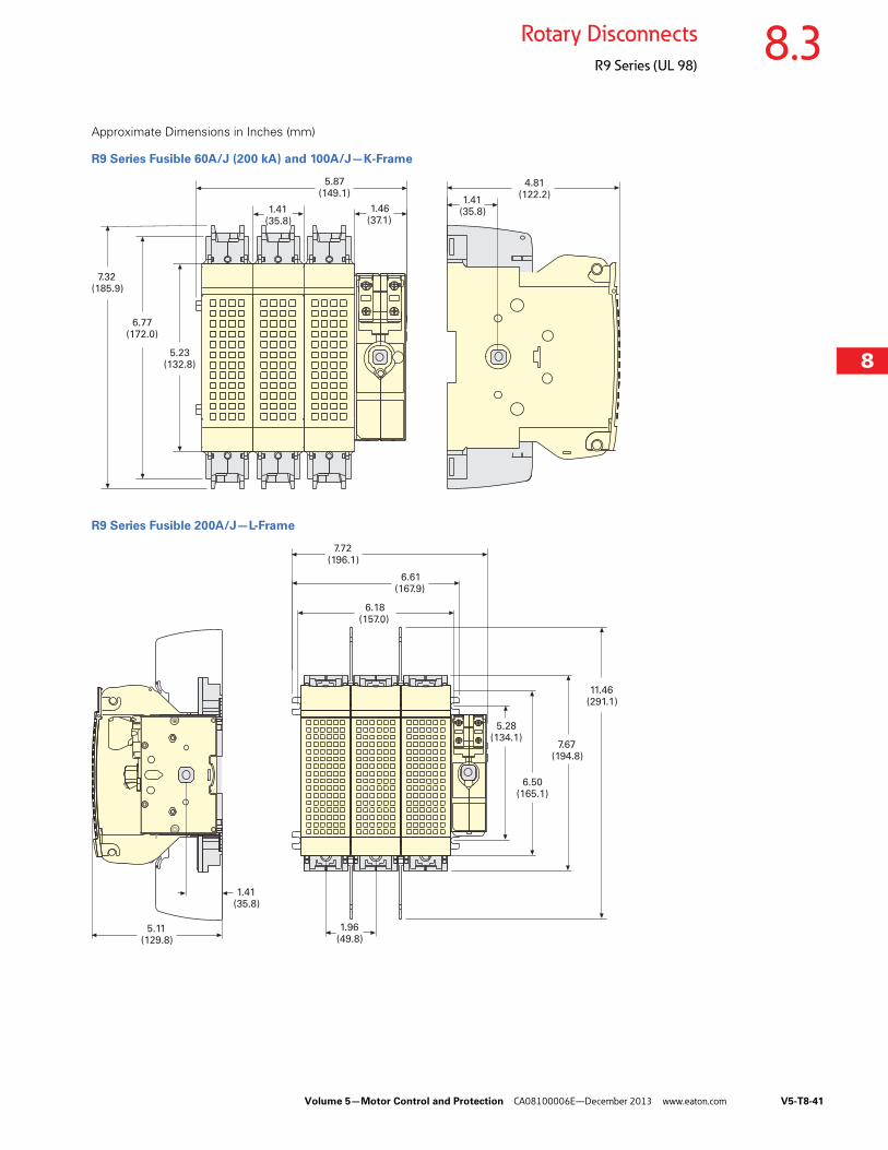
Volume 5—Motor Control and Protection CA08100006E—December 2013 www.eaton.com V5-T8-41
8
8
8
8
8
8
8
8
8
8
8
8
8
8
8
8
8
8
8
8
8
8
8
8
8
8
8
8
8
8
8.3Rotary Disconnects
R9 Series (UL 98)
Approximate Dimensions in Inches (mm)
R9 Series Fusible 60A/J (200 kA) and 100A/J—K-Frame
R9 Series Fusible 200A/J—L-Frame
7.32(185.9)
5.87(149.1)
1.41(35.8)
1.46(37.1)
4.81(122.2)
1.41(35.8)
6.77(172.0)
5.23(132.8)
7.72(196.1)
6.61(167.9)
6.18(157.0)
1.41(35.8)
5.11(129.8)
1.96(49.8)
5.28(134.1)
6.50(165.1)
7.67(194.8)
11.46(291.1)
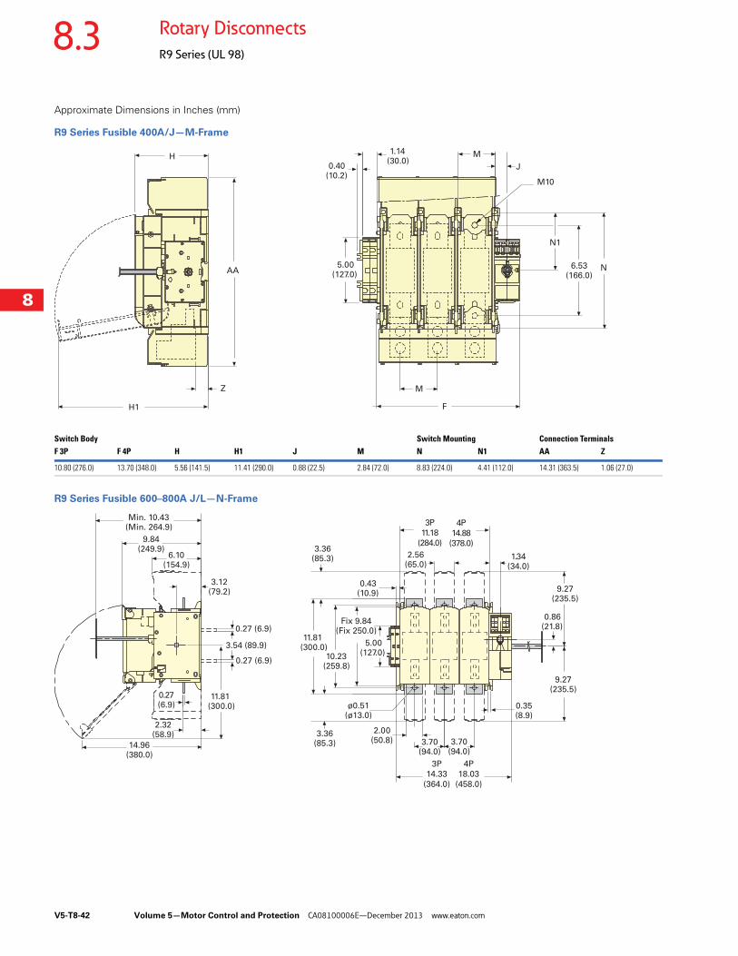
V5-T8-42 Volume 5—Motor Control and Protection CA08100006E—December 2013 www.eaton.com
8
8
8
8
8
8
8
8
8
8
8
8
8
8
8
8
8
8
8
8
8
8
8
8
8
8
8
8
8
8
8.3 Rotary Disconnects
R9 Series (UL 98)
Approximate Dimensions in Inches (mm)
R9 Series Fusible 400A/J—M-Frame
R9 Series Fusible 600–800A J/L—N-Frame
H
AA
H1
Z
0.40(10.2)
5.00(127.0)
1.14(30.0)
M
M10
J
F
M
N1
N6.53(166.0)
Switch Body Switch Mounting Connection TerminalsF 3P F 4P H H1 J M N N1 AA Z
10.80 (276.0) 13.70 (348.0) 5.56 (141.5) 11.41 (290.0) 0.88 (22.5) 2.84 (72.0) 8.83 (224.0) 4.41 (112.0) 14.31 (363.5) 1.06 (27.0)
9.84(249.9)
6.10(154.9)
3.12(79.2)
0.27(6.9)
2.32(58.9)
14.96(380.0)
Min. 10.43(Min. 264.9)
0.43(10.9)
2.56(65.0)
1.34(34.0)
0.35(8.9)
3.70(94.0)
3.70(94.0)
Fix 9.84(Fix 250.0)
5.00(127.0)
11.81(300.0)
0.86(21.8)
9.27(235.5)
9.27(235.5)
10.23(259.8)
3.36(85.3)
2.00(50.8)
ø0.51(ø13.0)
3.36(85.3)
11.81(300.0)
3.54 (89.9)
0.27 (6.9)
0.27 (6.9)
3P
14.33
(364.0)
4P
18.03
(458.0)
3P
11.18
(284.0)
4P
14.88
(378.0)
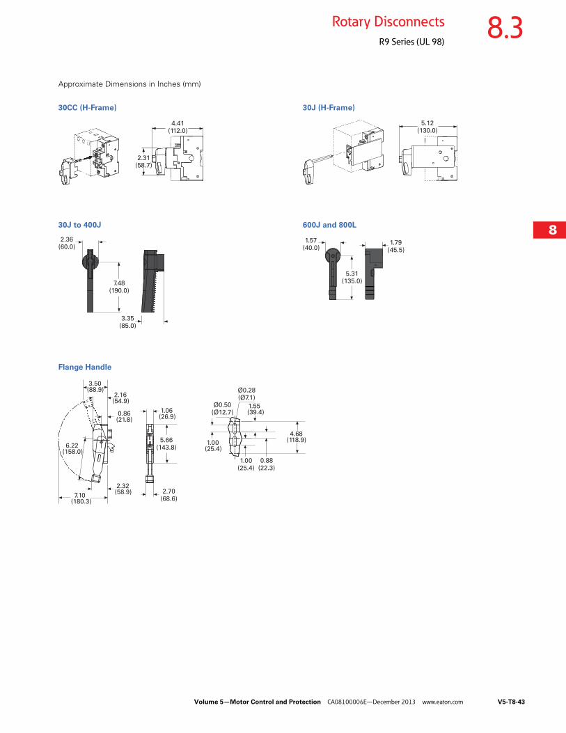
Volume 5—Motor Control and Protection CA08100006E—December 2013 www.eaton.com V5-T8-43
8
8
8
8
8
8
8
8
8
8
8
8
8
8
8
8
8
8
8
8
8
8
8
8
8
8
8
8
8
8
8.3Rotary Disconnects
R9 Series (UL 98)
Approximate Dimensions in Inches (mm)
30CC (H-Frame) 30J (H-Frame)
30J to 400J 600J and 800L
Flange Handle
4.41(112.0)
2.31(58.7)
5.12(130.0)
2.36(60.0)
7.48(190.0)
3.35(85.0)
1.57(40.0)
5.31(135.0)
1.79(45.5)
3.50(88.9)
2.16(54.9)
0.86(21.8)
1.06(26.9)
4.68(118.9)
1.55 (39.4)
0.88(22.3)
1.00(25.4)
1.00(25.4)
6.22(158.0)
2.32(58.9)
7.10(180.3)
Ø0.50(Ø12.7)
Ø0.28(Ø7.1)
2.70(68.6)
5.66(143.8)
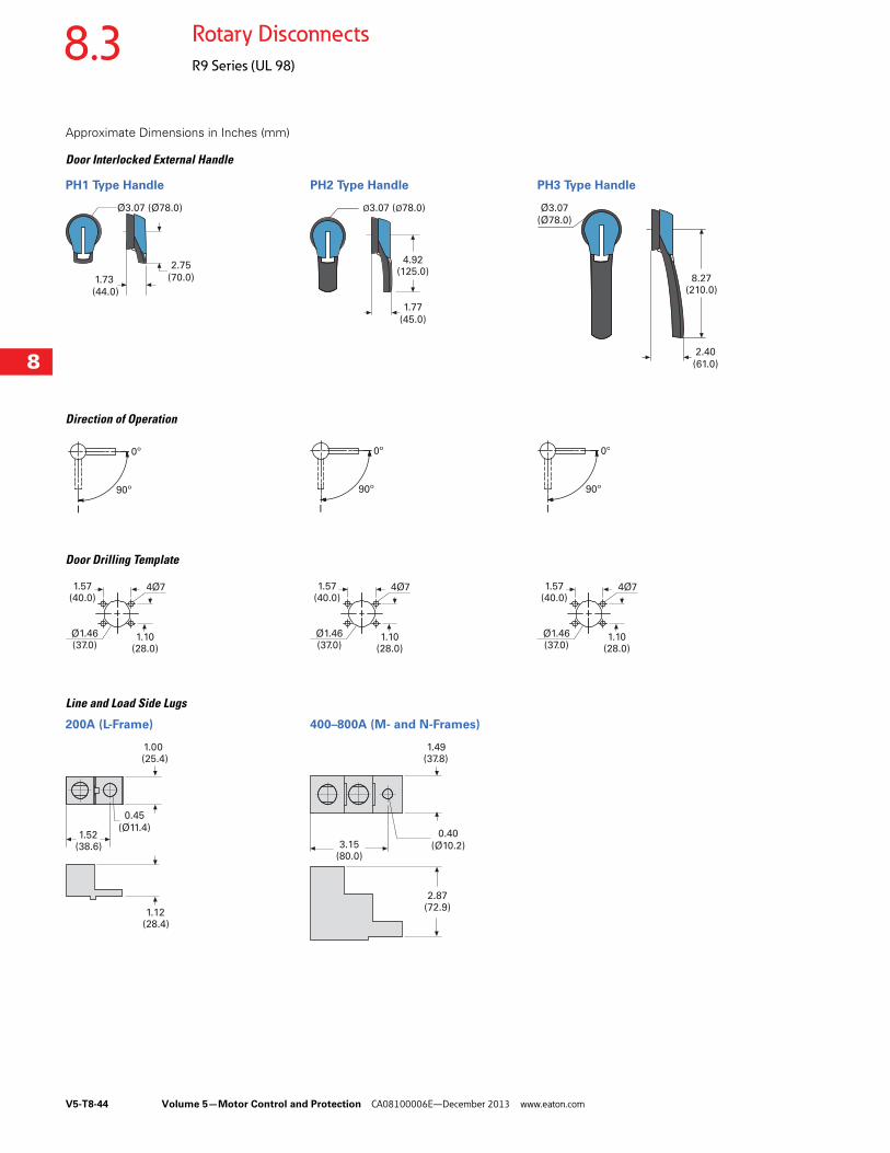
V5-T8-44 Volume 5—Motor Control and Protection CA08100006E—December 2013 www.eaton.com
8
8
8
8
8
8
8
8
8
8
8
8
8
8
8
8
8
8
8
8
8
8
8
8
8
8
8
8
8
8
8.3 Rotary Disconnects
R9 Series (UL 98)
Approximate Dimensions in Inches (mm)
Door Interlocked External Handle
PH1 Type Handle PH2 Type Handle PH3 Type Handle
Direction of Operation
Door Drilling Template
Line and Load Side Lugs
200A (L-Frame) 400–800A (M- and N-Frames)
2.75
(70.0)1.73
(44.0)
Ø3.07 (Ø78.0) Ø3.07 (Ø78.0)
4.92(125.0)
1.77
(45.0)
Ø3.07
(Ø78.0)
8.27(210.0)
2.40
(61.0)
90º
0º
I
90º
0º
I
90º
0º
I
1.57(40.0)
4Ø7
Ø1.46(37.0)
1.10(28.0)
1.57(40.0)
4Ø7
Ø1.46(37.0)
1.10(28.0)
1.57(40.0)
4Ø7
Ø1.46(37.0)
1.10(28.0)
1.00 (25.4)
1.52(38.6)
1.12(28.4)
0.45
(Ø11.4)
2.87(72.9)
3.15(80.0)
1.49(37.8)
0.40
(Ø10.2)
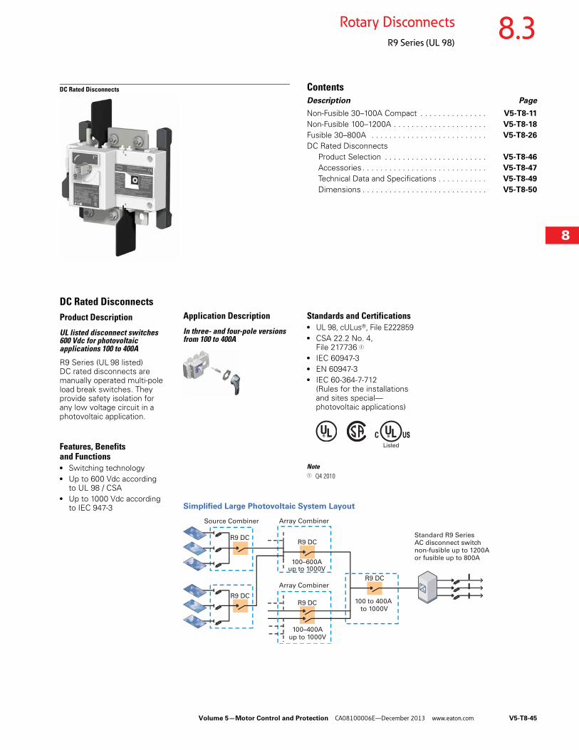
Volume 5—Motor Control and Protection CA08100006E—December 2013 www.eaton.com V5-T8-45
8
8
8
8
8
8
8
8
8
8
8
8
8
8
8
8
8
8
8
8
8
8
8
8
8
8
8
8
8
8
8.3Rotary Disconnects
R9 Series (UL 98)
DC Rated Disconnects ContentsDescription Page
Non-Fusible 30–100A Compact . . . . . . . . . . . . . . . V5-T8-11
Non-Fusible 100–1200A . . . . . . . . . . . . . . . . . . . . . V5-T8-18
Fusible 30–800A . . . . . . . . . . . . . . . . . . . . . . . . . . V5-T8-26
DC Rated Disconnects Product Selection . . . . . . . . . . . . . . . . . . . . . . . V5-T8-46
Accessories . . . . . . . . . . . . . . . . . . . . . . . . . . . . V5-T8-47
Technical Data and Specifications . . . . . . . . . . . V5-T8-49
Dimensions . . . . . . . . . . . . . . . . . . . . . . . . . . . . V5-T8-50
DC Rated DisconnectsProduct Description
UL listed disconnect switches 600 Vdc for photovoltaic applications 100 to 400A
R9 Series (UL 98 listed) DC rated disconnects are manually operated multi-pole load break switches. They provide safety isolation for any low voltage circuit in a photovoltaic application.
Features, Benefits and Functions● Switching technology● Up to 600 Vdc according
to UL 98 / CSA● Up to 1000 Vdc according
to IEC 947-3
Application Description
In three- and four-pole versions from 100 to 400A
Standards and Certifications● UL 98, cULus®, File E222859● CSA 22.2 No. 4,
File 217736 1
● IEC 60947-3● EN 60947-3● IEC 60-364-7-712
(Rules for the installations and sites special—photovoltaic applications)
Note1 Q4 2010
Simplified Large Photovoltaic System Layout
R9 DC
100 to 400A to 1000V
R9 DC
R9 DC
R9 DC
100–600Aup to 1000V
Array CombinerSource Combiner
R9 DC
100–400Aup to 1000V
Standard R9 Series AC disconnect switchnon-fusible up to 1200A or fusible up to 800A
Array Combiner
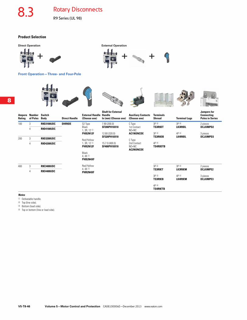
V5-T8-46 Volume 5—Motor Control and Protection CA08100006E—December 2013 www.eaton.com
8
8
8
8
8
8
8
8
8
8
8
8
8
8
8
8
8
8
8
8
8
8
8
8
8
8
8
8
8
8
8.3 Rotary Disconnects
R9 Series (UL 98)
Product Selection
Front Operation—Three- and Four-Pole
Notes1 Defeatable handle.2 Top (line side).3 Bottom (load side).4 Top or bottom (line or load side).
Ampere Rating
Number of Poles
Switch Body Direct Handle
External Handle (Choose one)
Shaft for External Handle In (mm) (Choose one)
Auxiliary Contacts (Choose one)
Terminals Shroud Terminal Lugs
Jumpers for Connecting Poles in Series
100 3 R9D3100UDC DHR9DE S2 Type Black 1, 3R, 12 1PHB2N12F
Red/Yellow 1, 3R, 12 1PHR2N12F
Black 4, 4X 1PHB2N4XF
Red/Yellow 4, 4X 1PHR2N4XF
7.90 (200.0)SF200PH10X10
12.60 (320.0)SF320PH10X10
15.7 0 (400.0)SF400PH10X10
C Type 1st Contact NO+NC AC1NONCDE
C Type 2nd Contact NO+NC AC2NONCDE
3P 2TS3R9DT
3P 3TS3R9DB
4P 4TS4R9DTB
3P 4LK3R9DL
4P 4LK4R9DL
2 piecesDCJUMPD2
3 piecesDCJUMPD3
4 R9D4100UDC
200 3 R9D3200UDC
4 R9D4200UDC
400 3 R9E3400UDC 3P 2
TS3R9ET
3P 3TS3R9EB
4P 4TS4R9ETB
3P 4LK3R9EM
4P 4LK4R9EM
2 piecesDCJUMPE2
3 piecesDCJUMPE3
4 R9E4400UDC
+ + +
Direct Operation External Operation
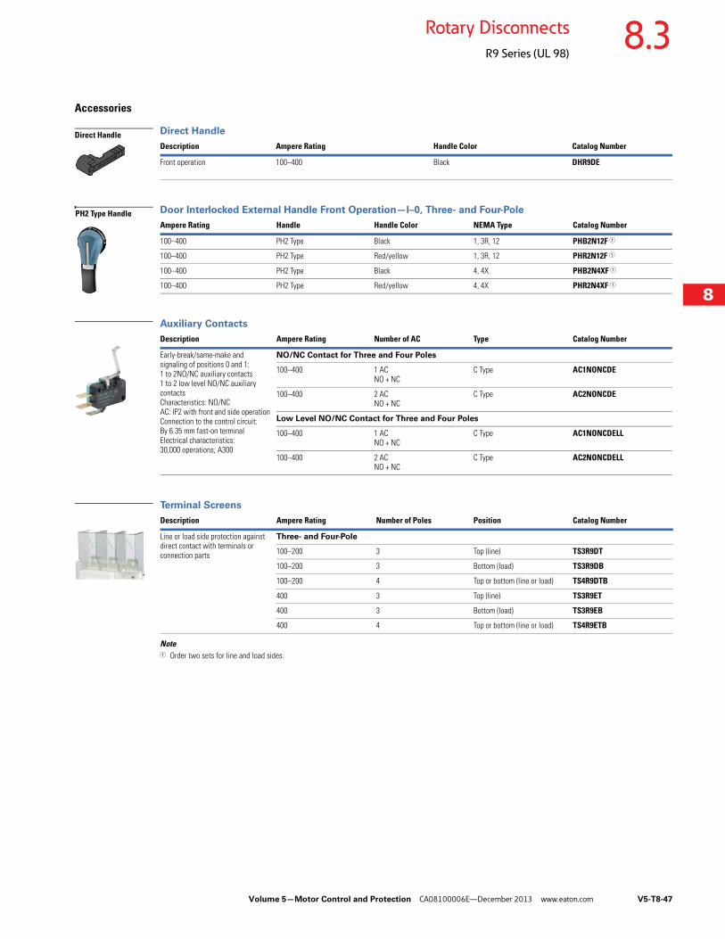
Volume 5—Motor Control and Protection CA08100006E—December 2013 www.eaton.com V5-T8-47
8
8
8
8
8
8
8
8
8
8
8
8
8
8
8
8
8
8
8
8
8
8
8
8
8
8
8
8
8
8
8.3Rotary Disconnects
R9 Series (UL 98)
Accessories
Direct Handle
Door Interlocked External Handle Front Operation—l–0, Three- and Four-Pole
Auxiliary Contacts
Terminal Screens
Note1 Order two sets for line and load sides.
Description Ampere Rating Handle Color Catalog Number
Front operation 100–400 Black DHR9DE
Ampere Rating Handle Handle Color NEMA Type Catalog Number
100–400 PH2 Type Black 1, 3R, 12 PHB2N12F 1
100–400 PH2 Type Red/yellow 1, 3R, 12 PHR2N12F 1
100–400 PH2 Type Black 4, 4X PHB2N4XF 1
100–400 PH2 Type Red/yellow 4, 4X PHR2N4XF 1
Description Ampere Rating Number of AC Type Catalog Number
Early-break/same-make and signaling of positions 0 and 1:1 to 2NO/NC auxiliary contacts1 to 2 low level NO/NC auxiliary contactsCharacteristics: NO/NC AC: IP2 with front and side operationConnection to the control circuit: By 6.35 mm fast-on terminalElectrical characteristics: 30,000 operations; A300
NO/NC Contact for Three and Four Poles
100–400 1 ACNO + NC
C Type AC1NONCDE
100–400 2 ACNO + NC
C Type AC2NONCDE
Low Level NO/NC Contact for Three and Four Poles
100–400 1 ACNO + NC
C Type AC1NONCDELL
100–400 2 ACNO + NC
C Type AC2NONCDELL
Description Ampere Rating Number of Poles Position Catalog Number
Line or load side protection against direct contact with terminals or connection parts
Three- and Four-Pole
100–200 3 Top (line) TS3R9DT
100–200 3 Bottom (load) TS3R9DB
100–200 4 Top or bottom (line or load) TS4R9DTB
400 3 Top (line) TS3R9ET
400 3 Bottom (load) TS3R9EB
400 4 Top or bottom (line or load) TS4R9ETB
Direct Handle
PH2 Type Handle
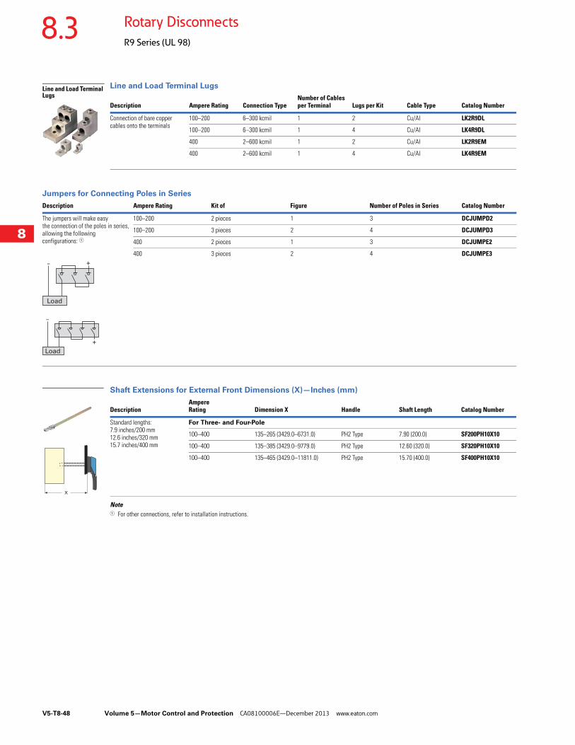
V5-T8-48 Volume 5—Motor Control and Protection CA08100006E—December 2013 www.eaton.com
8
8
8
8
8
8
8
8
8
8
8
8
8
8
8
8
8
8
8
8
8
8
8
8
8
8
8
8
8
8
8.3 Rotary Disconnects
R9 Series (UL 98)
Line and Load Terminal Lugs
Jumpers for Connecting Poles in Series
Shaft Extensions for External Front Dimensions (X)—Inches (mm)
Note1 For other connections, refer to installation instructions.
Description Ampere Rating Connection TypeNumber of Cables per Terminal Lugs per Kit Cable Type Catalog Number
Connection of bare copper cables onto the terminals
100–200 6–300 kcmil 1 2 Cu/Al LK2R9DL
100–200 6–300 kcmil 1 4 Cu/Al LK4R9DL
400 2–600 kcmil 1 2 Cu/Al LK2R9EM
400 2–600 kcmil 1 4 Cu/Al LK4R9EM
Description Ampere Rating Kit of Figure Number of Poles in Series Catalog Number
The jumpers will make easy the connection of the poles in series, allowing the following configurations: 1
100–200 2 pieces 1 3 DCJUMPD2
100–200 3 pieces 2 4 DCJUMPD3
400 2 pieces 1 3 DCJUMPE2
400 3 pieces 2 4 DCJUMPE3
DescriptionAmpere Rating Dimension X Handle Shaft Length Catalog Number
Standard lengths:7.9 inches/200 mm12.6 inches/320 mm15.7 inches/400 mm
For Three- and Four-Pole
100–400 135–265 (3429.0–6731.0) PH2 Type 7.90 (200.0) SF200PH10X10
100–400 135–385 (3429.0–9779.0) PH2 Type 12.60 (320.0) SF320PH10X10
100–400 135–465 (3429.0–11811.0) PH2 Type 15.70 (400.0) SF400PH10X10
Line and Load Terminal Lugs
- +
Load
Load
-
+
X
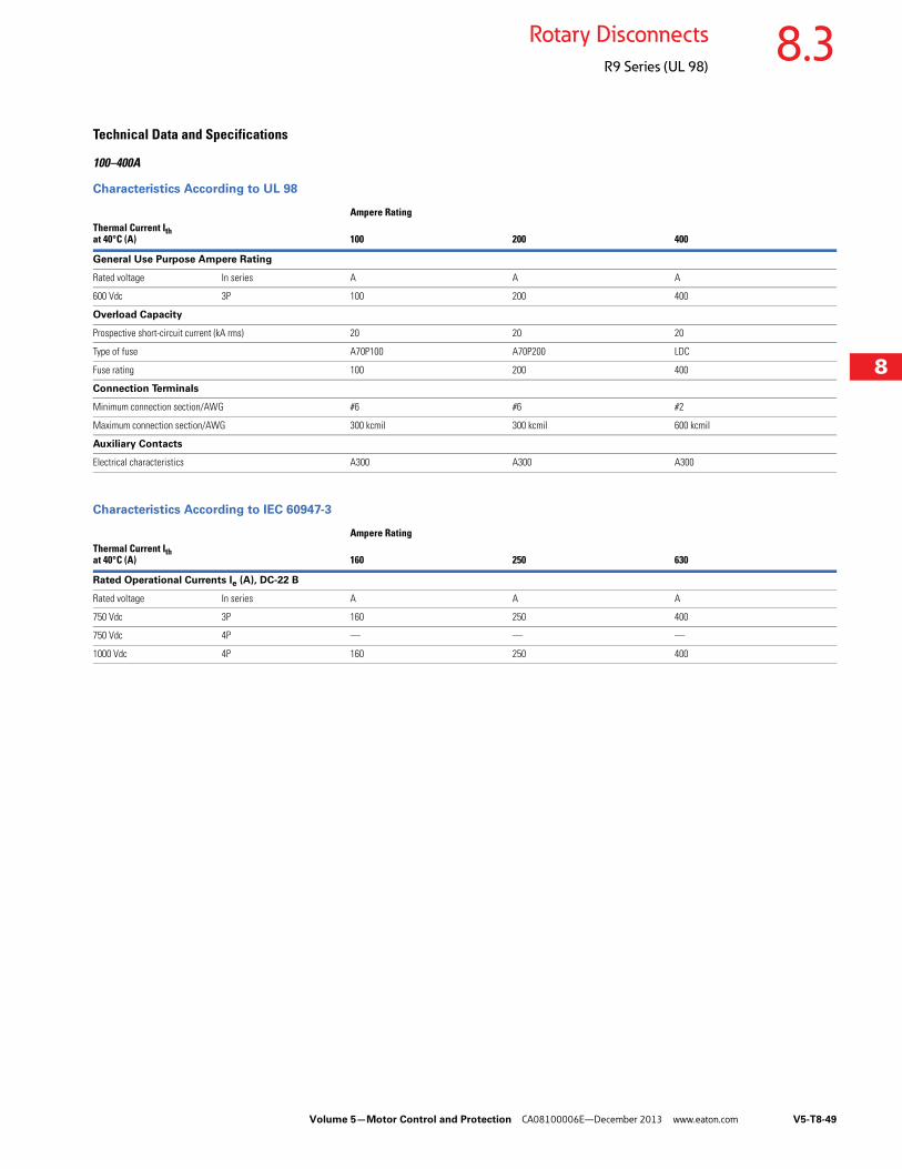
Volume 5—Motor Control and Protection CA08100006E—December 2013 www.eaton.com V5-T8-49
8
8
8
8
8
8
8
8
8
8
8
8
8
8
8
8
8
8
8
8
8
8
8
8
8
8
8
8
8
8
8.3Rotary Disconnects
R9 Series (UL 98)
Technical Data and Specifications
100–400A
Characteristics According to UL 98
Characteristics According to IEC 60947-3
Ampere RatingThermal Current Ith at 40°C (A) 100 200 400
General Use Purpose Ampere Rating
Rated voltage In series A A A
600 Vdc 3P 100 200 400
Overload Capacity
Prospective short-circuit current (kA rms) 20 20 20
Type of fuse A70P100 A70P200 LDC
Fuse rating 100 200 400
Connection Terminals
Minimum connection section/AWG #6 #6 #2
Maximum connection section/AWG 300 kcmil 300 kcmil 600 kcmil
Auxiliary Contacts
Electrical characteristics A300 A300 A300
Ampere RatingThermal Current Ith at 40°C (A) 160 250 630
Rated Operational Currents Ie (A), DC-22 B
Rated voltage In series A A A
750 Vdc 3P 160 250 400
750 Vdc 4P — — —
1000 Vdc 4P 160 250 400

V5-T8-50 Volume 5—Motor Control and Protection CA08100006E—December 2013 www.eaton.com
8
8
8
8
8
8
8
8
8
8
8
8
8
8
8
8
8
8
8
8
8
8
8
8
8
8
8
8
8
8
8.3 Rotary Disconnects
R9 Series (UL 98)
DimensionsApproximate Dimensions in Inches (mm)
R9 Series DC Rated Disconnects 100–400A
Front Operation
R9 Series DC Rated Disconnects
Ampere Rating C AC AD F 3P F 4P H J1 3P J1 4P K M 3P M 4P
100–200 3.72 (94.5) 10.10 (256.5) 3.05 (77.5) 7.09 (180.1) 9.06 (230.0) 4.22 (107.2) 2.17 (55.1) 4.13 (104.9) 1.80 (45.7) 6.30 (160.0) 8.27 (210.1)
400 4.92 (125.0) 16.00 (406.4) 4.51 (114.5) 9.05 (230.0) 11.40 (290.0) 6.53 (166.0) 2.95 (75.7) 5.31 (134.9) 2.65 (67.3) 8.26 (209.8) 10.60 (269.2)
Y
AC
K
CA
V
N AA
H
ZJ1 U
R1
M
ADT
F C
R2
W
The switch will operate correctly when rotated
clockwise 90 degrees.
The switch will not operate correctly when
rotated counterclockwise 90 degrees.
Ampere Rating N R1 R2 T U V W Y Z AA CA
100–200 5.31 (135.0) 0.35 (8.9) 0.27 (6.9) 1.97 (50.0) 0.98 (24.9) 1.18 (30.0) 0.43 (10.9) 0.14 (3.6) 1.35 (34.3) 6.30 (160.0) 0.60 (15.2)
400 7.60 (193.0) 0.35 (8.9) 0.27 (6.9) 2.56 (65.0) 1.77 (45.0) 1.97 (50.0) 0.43 (10.9) 0.20 (5.1) 2.08 (52.8) 10.20 (259.1) 0.80 (20.3)
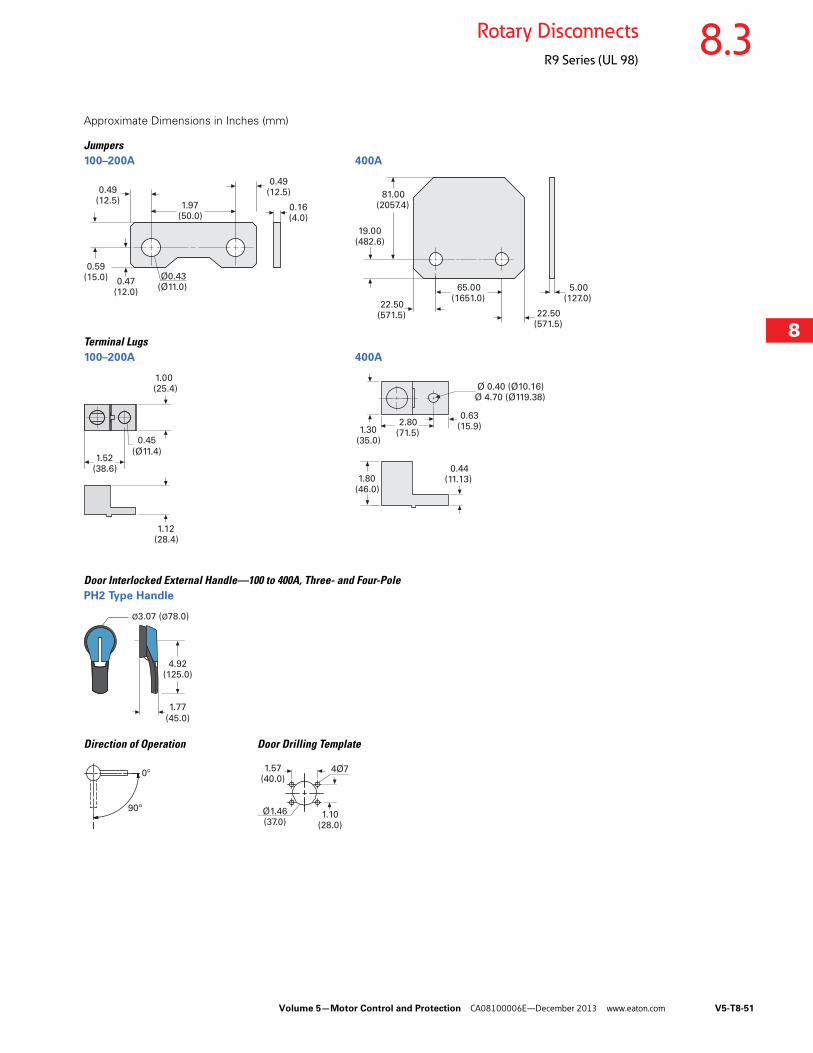
Volume 5—Motor Control and Protection CA08100006E—December 2013 www.eaton.com V5-T8-51
8
8
8
8
8
8
8
8
8
8
8
8
8
8
8
8
8
8
8
8
8
8
8
8
8
8
8
8
8
8
8.3Rotary Disconnects
R9 Series (UL 98)
Approximate Dimensions in Inches (mm)
Jumpers100–200A 400A
Terminal Lugs100–200A 400A
Door Interlocked External Handle—100 to 400A, Three- and Four-PolePH2 Type Handle
Direction of Operation Door Drilling Template
22.50(571.5)
19.00(482.6)
81.00(2057.4)
22.50(571.5)
5.00(127.0)
65.00(1651.0)
0.49(12.5)
Ø0.43(Ø11.0)
0.47(12.0)
0.59(15.0)
1.97(50.0)
0.49(12.5)
0.16(4.0)
1.00 (25.4)
1.52(38.6)
1.12(28.4)
0.45
(Ø11.4)
2.80(71.5)
Ø 0.40 (Ø10.16)Ø 4.70 (Ø119.38)
1.30(35.0)
1.80(46.0)
0.44(11.13)
0.63(15.9)
Ø3.07 (Ø78.0)
4.92(125.0)
1.77
(45.0)
90º
0º
I
1.57(40.0)
4Ø7
Ø1.46(37.0)
1.10(28.0)
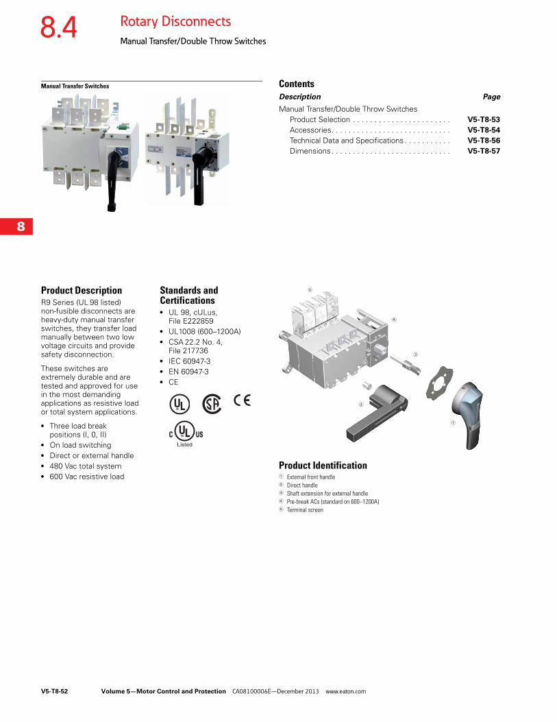
V5-T8-52 Volume 5—Motor Control and Protection CA08100006E—December 2013 www.eaton.com
8
8
8
8
8
8
8
8
8
8
8
8
8
8
8
8
8
8
8
8
8
8
8
8
8
8
8
8
8
8
8.4 Rotary Disconnects
Manual Transfer/Double Throw Switches
Manual Transfer Switches ContentsDescription Page
Manual Transfer/Double Throw Switches Product Selection . . . . . . . . . . . . . . . . . . . . . . . V5-T8-53
Accessories. . . . . . . . . . . . . . . . . . . . . . . . . . . . V5-T8-54
Technical Data and Specifications . . . . . . . . . . . V5-T8-56
Dimensions. . . . . . . . . . . . . . . . . . . . . . . . . . . . V5-T8-57
Product DescriptionR9 Series (UL 98 listed) non-fusible disconnects are heavy-duty manual transfer switches, they transfer load manually between two low voltage circuits and provide safety disconnection.
These switches are extremely durable and are tested and approved for use in the most demanding applications as resistive load or total system applications.
● Three load break positions (I, 0, II)
● On load switching● Direct or external handle● 480 Vac total system● 600 Vac resistive load
Standards and Certifications ● UL 98, cULus,
File E222859● UL1008 (600–1200A)● CSA 22.2 No. 4,
File 217736● IEC 60947-3● EN 60947-3● CE
Product Identification1 External front handle2 Direct handle3 Shaft extension for external handle4 Pre-break ACs (standard on 600–1200A)5 Terminal screen
5
4
1
3
2

Volume 5—Motor Control and Protection CA08100006E—December 2013 www.eaton.com V5-T8-53
8
8
8
8
8
8
8
8
8
8
8
8
8
8
8
8
8
8
8
8
8
8
8
8
8
8
8
8
8
8
8.4Rotary Disconnects
Manual Transfer/Double Throw Switches
Product Selection
Manual Transfer/Double Throw Switches—UL 98 Standard 1
Notes1 All ratings, 100–1200A, are UL 98 listed. Switches rated 600–1200A are UL 1008 listed as well.2 Line or load (top or bottom); for both line and load, order two kits.3 Low level auxiliary contact—gold plated for minimal resistance—for PLC applications.
Ampere Rating
Number of Poles
Switch Body Only 1
Direct Handle (Black)
External Three-Position Handle(Choose one)
Shaft Extensions for External HandleIn (mm) (Choose one)
Bridging Bars
Auxiliary Contacts
Terminal Screens 2
100 3 RMTS3100U DHMTSSL Size 2, BlackI–0–IIType 4/4XPHB2N4X3P
Size 2, RedI–0–IIType 4/4XPHR2N4X3P
7.90 (200.6)SF200PH10X10
12.60 (320.0)SF320PH10X10
15.70 (398.8)SF400PH10X10
3PBB3P200
4PBB4P200
NO/NCAC1NONCMTS400
Low levelAC1NONCMTS400LL 3
3PTS3MTS200TB
4PTS4MTS200TB
4 RMTS4100U
200 3 RMTS3200U
4 RMTS4200U
400 3 RMTS3400U Size 3, BlackI–0–IIType 4/4XPHB3N4X3P
Size 3, RedI–0–IIType 4/4XPHR3N4X3P
7.90 (200.6)SF200PH15X12
12.60 (320.0)SF320PH15X12
15.70 (398.8)SF400PH15X12
3PBB3P400
4PBB4P400
3PTS3MTS400TB
4PTS4MTS400TB
4 RMTS4400U
600 3 RMTS3600U DHMTSDL Size 4, BlackI–0–IIType 4/4XPHB4N4X3P
Size 4, RedI–0–IIType 4/4XPHR4N4X3P
3PBB3P600
4PBB4P600
NO/NC contact standard
3PTS3MTS600
4PTS4MTS600
4 RMTS4600U
800 3 RMTS3800U DHMTSDLM 3PBB3P1200
4PBB4P1200
3PTS3MTS1200
4PTS4MTS1200
4 RMTS4800U
1200 3 RMTS31200U
4 RMTS41200U
+ + +Switch body Direct handle Switch body Shaft External handle+ + +
Direct Operation External Operation
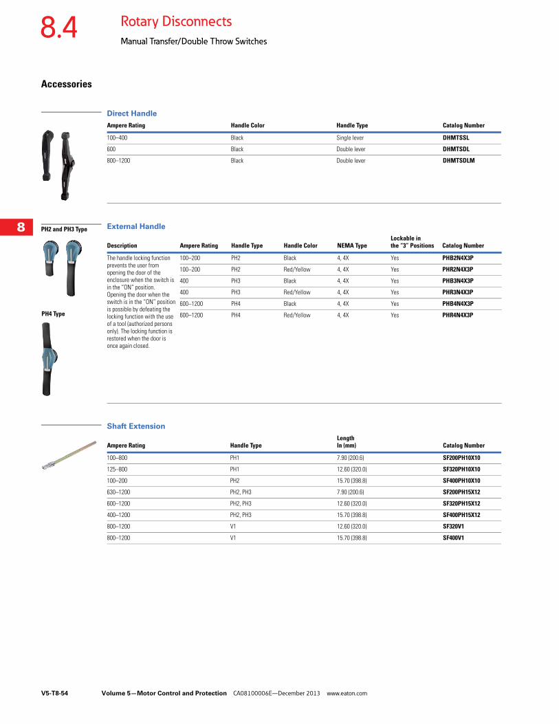
V5-T8-54 Volume 5—Motor Control and Protection CA08100006E—December 2013 www.eaton.com
8
8
8
8
8
8
8
8
8
8
8
8
8
8
8
8
8
8
8
8
8
8
8
8
8
8
8
8
8
8
8.4 Rotary Disconnects
Manual Transfer/Double Throw Switches
Accessories
Direct Handle
External Handle
Shaft Extension
Ampere Rating Handle Color Handle Type Catalog Number
100–400 Black Single lever DHMTSSL
600 Black Double lever DHMTSDL
800–1200 Black Double lever DHMTSDLM
Description Ampere Rating Handle Type Handle Color NEMA TypeLockable inthe “3” Positions Catalog Number
The handle locking function prevents the user from opening the door of theenclosure when the switch is in the “ON” position.Opening the door when the switch is in the “ON” position is possible by defeating the locking function with the use of a tool (authorized persons only). The locking function is restored when the door is once again closed.
100–200 PH2 Black 4, 4X Yes PHB2N4X3P
100–200 PH2 Red/Yellow 4, 4X Yes PHR2N4X3P
400 PH3 Black 4, 4X Yes PHB3N4X3P
400 PH3 Red/Yellow 4, 4X Yes PHR3N4X3P
600–1200 PH4 Black 4, 4X Yes PHB4N4X3P
600–1200 PH4 Red/Yellow 4, 4X Yes PHR4N4X3P
Ampere Rating Handle TypeLength In (mm) Catalog Number
100–800 PH1 7.90 (200.6) SF200PH10X10
125–800 PH1 12.60 (320.0) SF320PH10X10
100–200 PH2 15.70 (398.8) SF400PH10X10
630–1200 PH2, PH3 7.90 (200.6) SF200PH15X12
600–1200 PH2, PH3 12.60 (320.0) SF320PH15X12
400–1200 PH2, PH3 15.70 (398.8) SF400PH15X12
800–1200 V1 12.60 (320.0) SF320V1
800–1200 V1 15.70 (398.8) SF400V1
PH4 Type
PH2 and PH3 Type

Volume 5—Motor Control and Protection CA08100006E—December 2013 www.eaton.com V5-T8-55
8
8
8
8
8
8
8
8
8
8
8
8
8
8
8
8
8
8
8
8
8
8
8
8
8
8
8
8
8
8
8.4Rotary Disconnects
Manual Transfer/Double Throw Switches
Bridging Bars
Terminals Protection Screen
Mounting Spacers
Auxiliary Contacts
Line and Load Terminal Lugs
Note1 Gold plated for minimal resistance—for PLC applications.
Description Ampere Rating Number of Bridging Bars Catalog Number
Creation of a common point, above or below the switch, between positions I and II.
100 –200 3 BB3P200
100–200 4 BB4P200
400 3 BB3P400
400 4 BB4P400
600 3 BB3P600
600 4 BB4P600
800–1200 3 BB3P1200
800–1200 4 BB4P1200
Description Ampere Rating Number of Poles Catalog Number
Top or bottom (line or load) protection against direct contacts with terminal or connecting parts.
100–200 3 TS3MTS200TB
100–200 4 TS4MTS200TB
400 3 TS3MTS400TB
400 4 TS4MTS400TB
600 6 TS3MTS600
600 4 TS4MTS600
800–1200 3 TS3MTS1200
800–1200 4 TS4MTS1200
Description Ampere Rating Number of Poles Catalog Number
Raises the device’s terminals 10 mm away from the bottom of the enclosure or frame on which the device is mounted.
100–400 1 set of 2 spacers MSP400
Description Ampere Rating Contact(s) Catalog Number
Early-break/same-make and signalization per position 1 and 2. Electrical characteristics: A300.
100–400 1NO/NC per position 1 and 2 AC1NONCMTS400
100–400 1NO/NC per position 1 and 2 low level AC1NONCMTS400LL 1
600–1200 1NO/NC per position 1 and 2 Standard
Description Ampere RatingConnection Type
Number of Poles
Number of Cables/Lug Lugs per Kit Cable Type Catalog Number
Connection of bare copper cables onto the terminals (without spade lugs).
100–200 6–300 kcmil 3 1 3 Cu/Al LK3R9DL
100–200 6–300 kcmil 4 1 4 Cu/Al LK4R9DL
400 4–600 kcmil 3 1 3 Cu/Al LK3R9EM
400 4–600 kcmil 4 1 4 Cu/Al LK4R9EM
600 2x (#2–600 kcmil) 3 2 3 Cu/Al LK3R9FN
600 2x (#2–600 kcmil) 4 2 4 Cu/Al LK4R9FN
800–1200 2x (#2–600 kcmil) 3 2 6 Cu/Al LK6R9G
800–1200 2x (#2 –600 kcmil) 4 2 8 Cu/Al LK8R9G
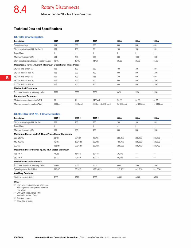
V5-T8-56 Volume 5—Motor Control and Protection CA08100006E—December 2013 www.eaton.com
8
8
8
8
8
8
8
8
8
8
8
8
8
8
8
8
8
8
8
8
8
8
8
8
8
8
8
8
8
8
8.4 Rotary Disconnects
Manual Transfer/Double Throw Switches
Technical Data and Specifications
UL 1008 Characteristics
UL 98/CSA 22.2 No. 4 Characteristics
Notes1 Short-circuit rating achieved when used
with respective fuse type and maximum fuse rating.
2 Only UL 98 listed. For UL 1008 availability, contact Eaton.
3 Two-pole in series.4 Three-pole in series.
Description 100A 200A 400A 600A 800A 1200A
Operation voltage 600 600 600 600 600 600
Short-circuit rating at 600 Vac (kA) 1 100 100 65 100 100 100
Type of fuse J J J L L L
Maximum fuse rating (A) 200 400 600 800 1000 1600
Short-circuit rating with circuit breaker (kA/ms) 10/25 10/25 14/50 35/50 35/50 35/50
Operational Power/Current Maximum Operational Three-Phase
240 Vac total system (A) 100 100 250 400 700 700
240 Vac resistive load (A) 100 200 400 600 800 1200
480 Vac total system (A) 100 100 125 350 600 600
480 Vac resistive load (A) 100 200 400 600 800 1200
600 Vac resistive load (A) 100 200 400 400 800 1200
Mechanical Endurance
Endurance (number of operating cycles) 6050 6050 6050 6050 3550 3550
Connection Terminals
Minimum connection section/AWG #6 #6 #4/2 x #6 2x #2 4x #2 4x #2
Maximum connection section/AWG 300 kcmil 300 kcmil 600 kcmil/2x 350 kcmil 2x 600 kcmil 4x 600 kcmil 4x 600 kcmil
Description 100A 2 200A 2 400A 2 600A 800A 1200A
Short-circuit rating at 600 Vac (kA) 200 200 200 200 100 100
Type of fuse J J J J L L
Maximum fuse rating (A) 100 200 400 600 800 1200
Maximum Motor, hp/FLA Three-Phase Motor Maximum
220–240 Vac 30/80 75/192 125/312 200/480 200/480 200/480
440–480 Vac 75/96 180/180 250/302 400/477 500/590 500/590
600 Vac 100/99 200/192 350/336 350/336 500/472 500/472
Maximum Motor Power, hp/DC FLA Motor Maximum
125 Vdc 3 7.5/58 15/112 20/148 20/148 — —
250 Vdc 4 20/72 40/140 50/173 50/173 — —
Mechanical Characteristics
Endurance (number of operating cycles) 10,000 8000 6000 6000 3500 3500
Operating torque (lbs.in/Nm) 88.5/10 88.5/10 128.3/14.5 327.5/37 442.5/50 442.5/50
Auxiliary Contacts
Electrical characteristics A300 A300 A300 A300 A300 A300
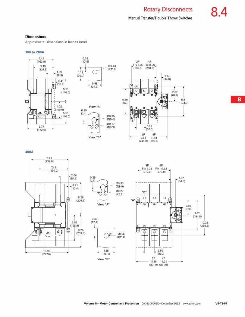
Volume 5—Motor Control and Protection CA08100006E—December 2013 www.eaton.com V5-T8-57
8
8
8
8
8
8
8
8
8
8
8
8
8
8
8
8
8
8
8
8
8
8
8
8
8
8
8
8
8
8
8.4Rotary Disconnects
Manual Transfer/Double Throw Switches
DimensionsApproximate Dimensions in Inches (mm)
100 to 200A
400A
6.41(162.8)
5.19(131.8)
1.53(38.9)
5.51(140.0)
4.29(109.0)
6.77(172.0)
5.51(140.0)
0.41(10.4)
1.18(30.0)
0.98(24.9)
1.37(34.8)
0.53(13.5)
Ø0.43Ø(11.0)
View “A”
View “B”
“B”
“A”
Ø0.35Ø(9.0)
Ø0.27Ø(6.9)
0.29(7.4)
1.97(50.0)
6.30(160)
5.31(134.9)
2.67(67.8)
3P Fix 6.30(160.0)
4PFix 8.26(210.0)
3P9.64
(245.0)
4P11.41
(290.0)
9.41(239.0)
7.48(190.0)
2.04(51.8)
0.41(10.4)
View “A”
View “B”
Ø0.35Ø(9.0)
Ø0.27Ø(6.9)
0.29(7.4)
8.26(209.8)
8.26(209.8)
6.53(165.9)
10.90(277.0)
“A”
1.38(35.1)
Ø0.43Ø(11.0)
0.49(12.4)
“B”
1.37(34.8)
7.67(194.8)
3.85(97.8)
10.23(259.8)
2.56(65.0)
3PFix 8.26(210.0)
4PFix 10.63(270.0)
3P11.85
(301.0)
4P14.21
(361.0)
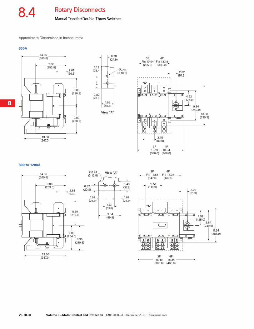
V5-T8-58 Volume 5—Motor Control and Protection CA08100006E—December 2013 www.eaton.com
8
8
8
8
8
8
8
8
8
8
8
8
8
8
8
8
8
8
8
8
8
8
8
8
8
8
8
8
8
8
8.4 Rotary Disconnects
Manual Transfer/Double Throw Switches
Approximate Dimensions in Inches (mm)
600A
800 to 1200A
14.56(369.8)
9.98(253.5)
2.61(66.3)
9.09(230.9)
9.09(230.9)
13.66(347.0)
View “A”
“A”
Ø0.41Ø(10.5)
1.12(28.4)
0.82(20.8)
1.96(49.8)
0.98(24.9)
2.02(51.3)
4.92(125.0)
9.84(249.9)
13.38(339.9)
3.15(80.0)
3PFix 10.04(255.0)
4PFix 13.18(335.0)
3P15.19
(386.0)
4P18.34
(466.0)
14.56(369.8)
9.98(253.5)
2.65(67.3)
8.30(210.8)
8.30(210.8)
8.03(204.0)
13.66(347.0)
Ø0.41Ø(10.5)
View “A”
“A”
3.54(89.9)
1.49(37.8)
1.02(25.9)
0.82(20.8)
1.02(25.9)
1.49(37.8)
2.02(51.3)
11.34(288.0)
4.72(119.9)
9.84(249.9)
4.92(125.0)
3PFix 13.66
(347.0)
4PFix 18.38
(467.0)
3P15.19
(386.0)
4P18.34
(466.0)
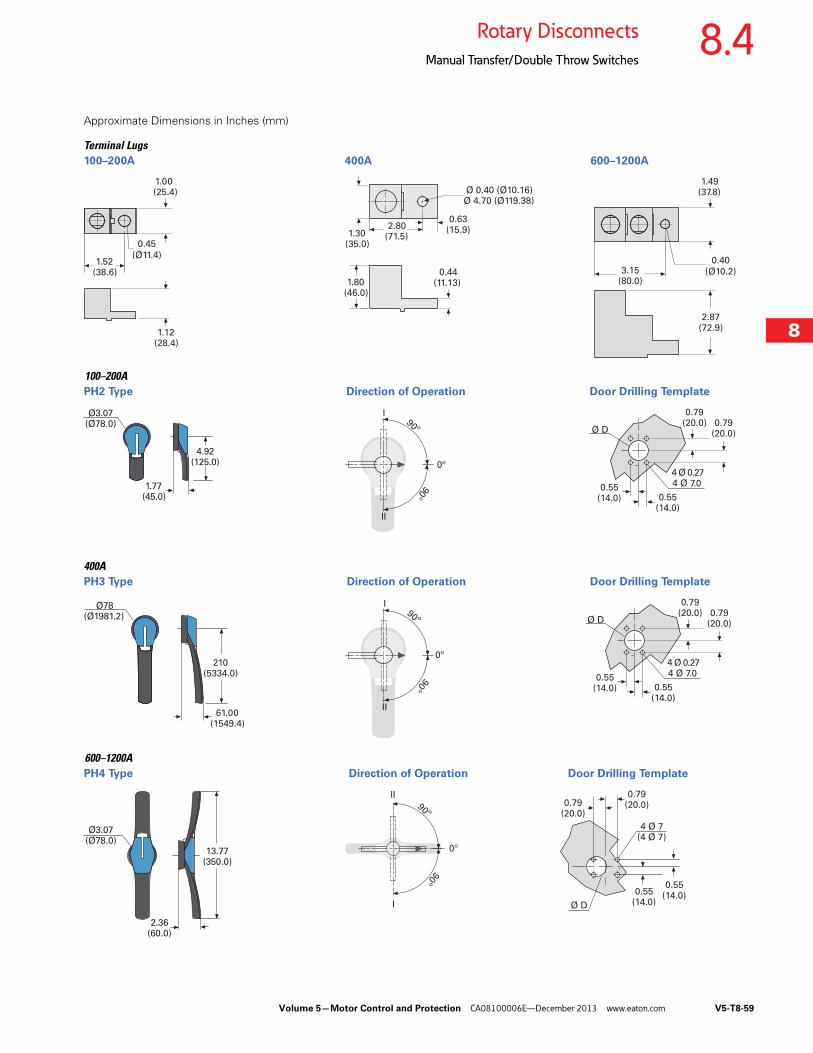
Volume 5—Motor Control and Protection CA08100006E—December 2013 www.eaton.com V5-T8-59
8
8
8
8
8
8
8
8
8
8
8
8
8
8
8
8
8
8
8
8
8
8
8
8
8
8
8
8
8
8
8.4Rotary Disconnects
Manual Transfer/Double Throw Switches
Approximate Dimensions in Inches (mm)
Terminal Lugs100–200A 400A 600–1200A
100–200APH2 Type Direction of Operation Door Drilling Template
400APH3 Type Direction of Operation Door Drilling Template
600–1200APH4 Type Direction of Operation Door Drilling Template
1.00 (25.4)
1.52(38.6)
1.12(28.4)
0.45
(Ø11.4)
2.80(71.5)
Ø 0.40 (Ø10.16)Ø 4.70 (Ø119.38)
1.30(35.0)
1.80(46.0)
0.44(11.13)
0.63(15.9)
2.87(72.9)
3.15(80.0)
1.49(37.8)
0.40
(Ø10.2)
Ø3.07(Ø78.0)
1.77(45.0)
4.92(125.0)
4 Ø 0.274 Ø 7.0
Ø D90º
90º
I
II
0.79(20.0)
0º
0.79(20.0)
0.55(14.0) 0.55
(14.0)
Ø78(Ø1981.2)
61.00(1549.4)
210(5334.0)
90º
90º
I
II
0º4 Ø 0.274 Ø 7.0
Ø D0.79
(20.0)
0.79(20.0)
0.55(14.0) 0.55
(14.0)
0º
I
II
2.36(60.0)
13.77(350.0)
4 Ø 7(4 Ø 7)
Ø D
90º
90º
0.79(20.0)
Ø3.07(Ø78.0)
0.79(20.0)
0.55(14.0)
0.55(14.0)
V5-T8-60 Volume 5—Motor Control and Protection CA08100006E—December 2013 www.eaton.com
8
8
8
8
8
8
8
8
8
8
8
8
8
8
8
8
8
8
8
8
8
8
8
8
8
8
8
8
8
8
8.4 Rotary Disconnects
Manual Transfer/Double Throw Switches
Recommended
![02363011 - [GB] - T8-Netzwork- und MY.ZSK-Einrichtung · IP Adress of T8-/T8-2 control in local network 2.2 IP Adress of T8-/T8-2 control in local network In a network, the IP addresses](https://img.pdfslide.us/doc/110x75/5f07578e7e708231d41c8223/02363011-gb-t8-netzwork-und-myzsk-einrichtung-ip-adress-of-t8-t8-2-control.jpg)