Rendering Pipeline
Teacher: A.prof. Chengying Gao(高成英)
E-mail: [email protected]
School of Data and Computer Science
Computer Graphics
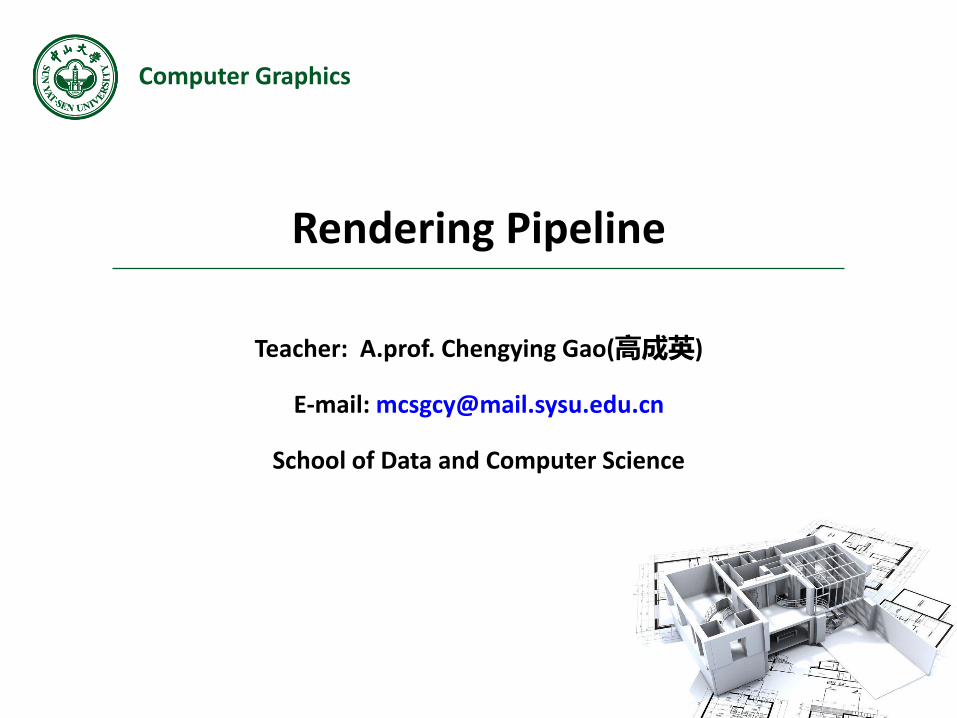
Outline
• Computer Graphics System
• Physical Imaging System
• Graphics Rendering Pipeline
2Computer Graphics
Example
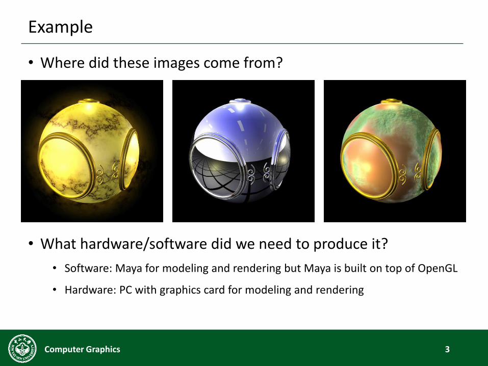
• Where did these images come from?
• What hardware/software did we need to produce it?
• Software: Maya for modeling and rendering but Maya is built on top of OpenGL
• Hardware: PC with graphics card for modeling and rendering
3Computer Graphics
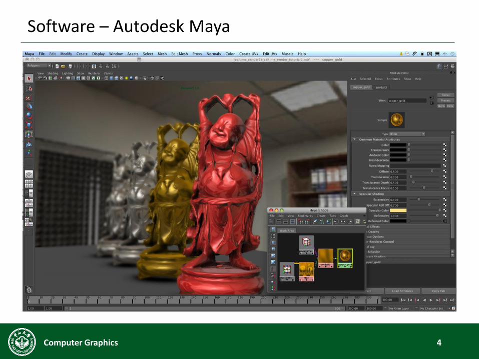
Software – Autodesk Maya
4Computer Graphics
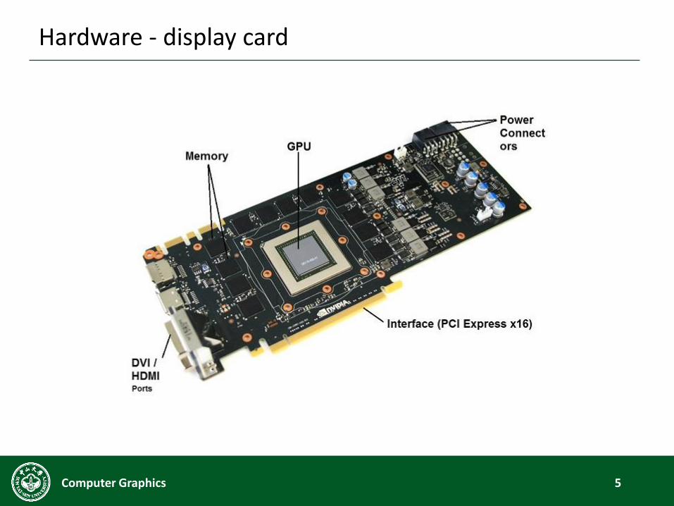
Hardware - display card
5Computer Graphics
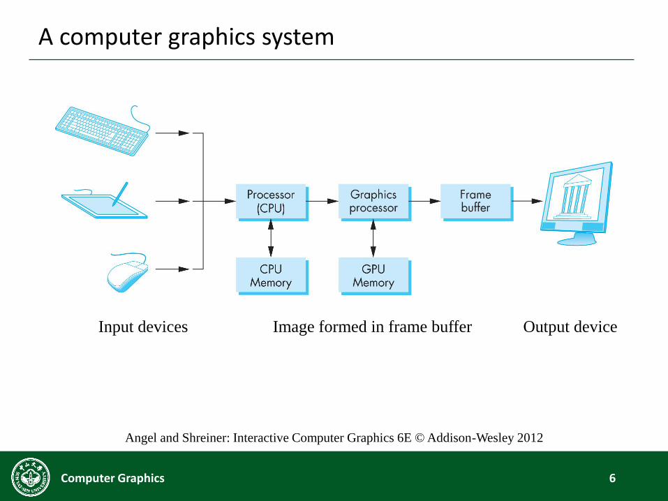
A computer graphics system
6Computer Graphics
Input devices Output deviceImage formed in frame buffer
Angel and Shreiner: Interactive Computer Graphics 6E © Addison-Wesley 2012
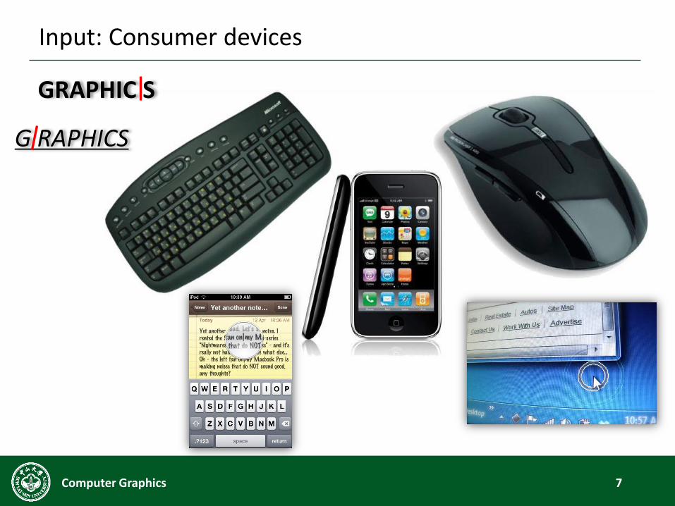
Input: Consumer devices
7Computer Graphics
GRAPHIC S
G RAPHICS

Input: Image & video
8Computer Graphics

The modern era of easy photography
9Computer Graphics
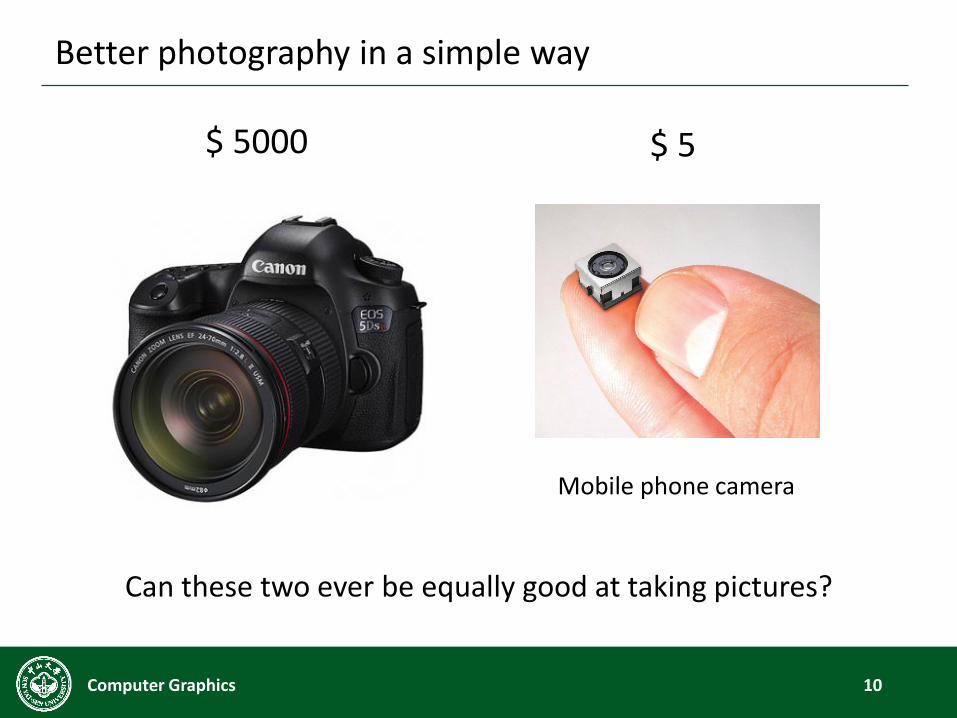
Better photography in a simple way
10Computer Graphics
$ 5000 $ 5
Can these two ever be equally good at taking pictures?
Mobile phone camera
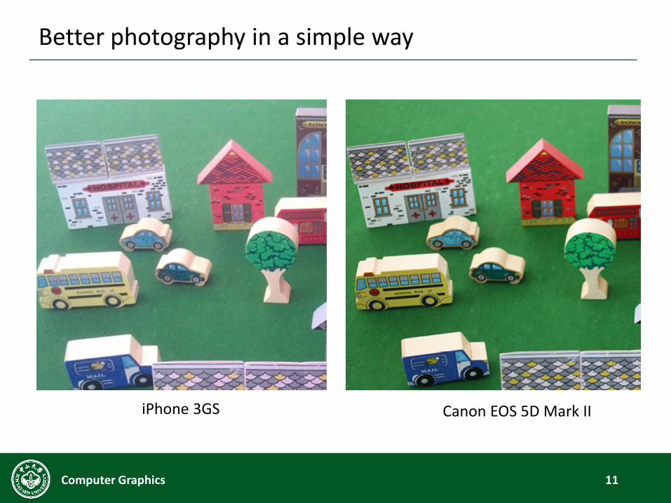
Better photography in a simple way
11Computer Graphics
iPhone 3GS Canon EOS 5D Mark II
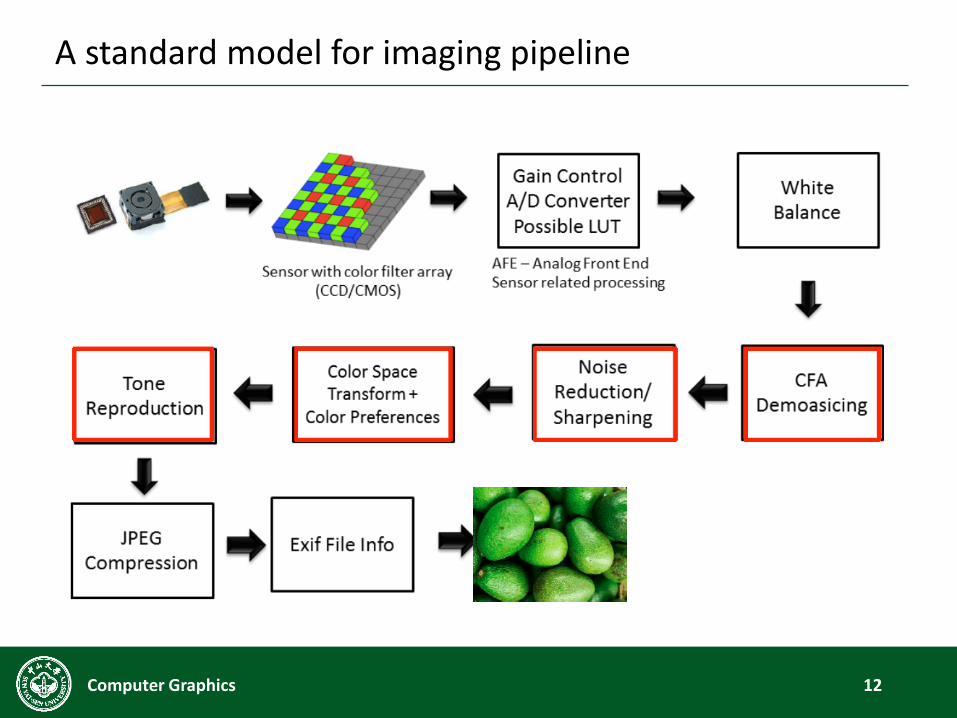
A standard model for imaging pipeline
12Computer Graphics
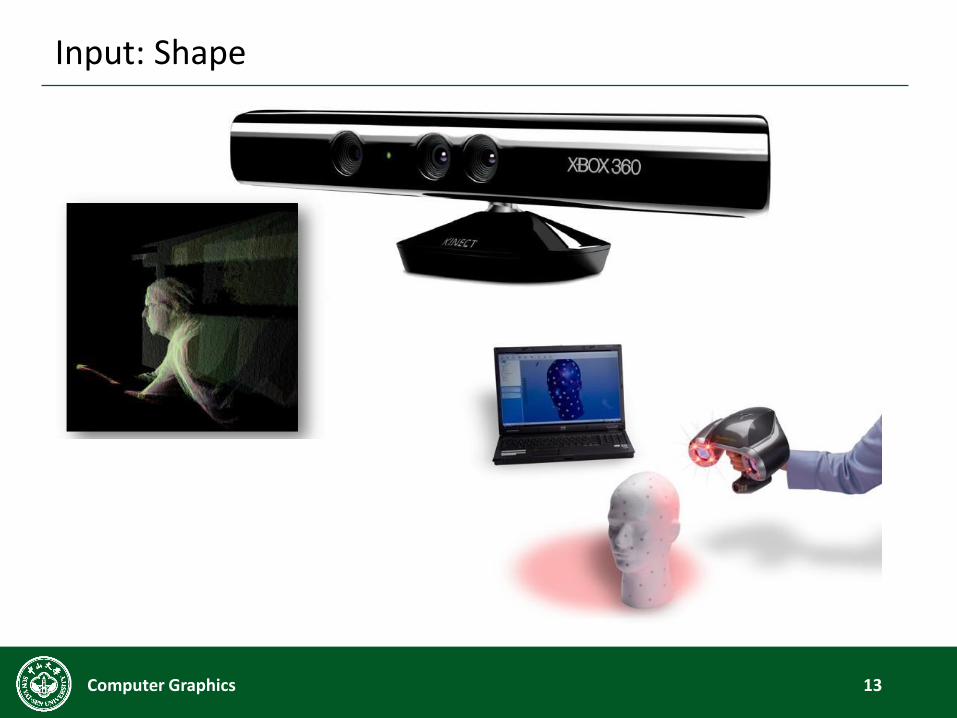
Input: Shape
13Computer Graphics

Kinect Fusion
14Computer Graphics
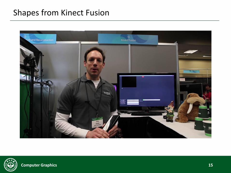
Shapes from Kinect Fusion
15Computer Graphics
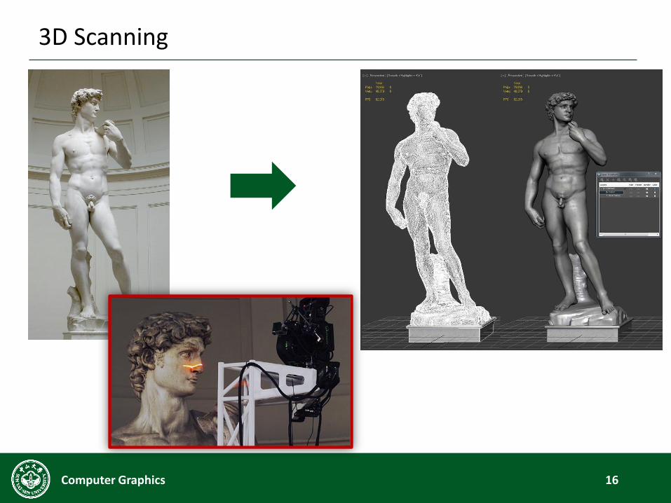
3D Scanning
16Computer Graphics
Desktop 3D scanner
17Computer Graphics
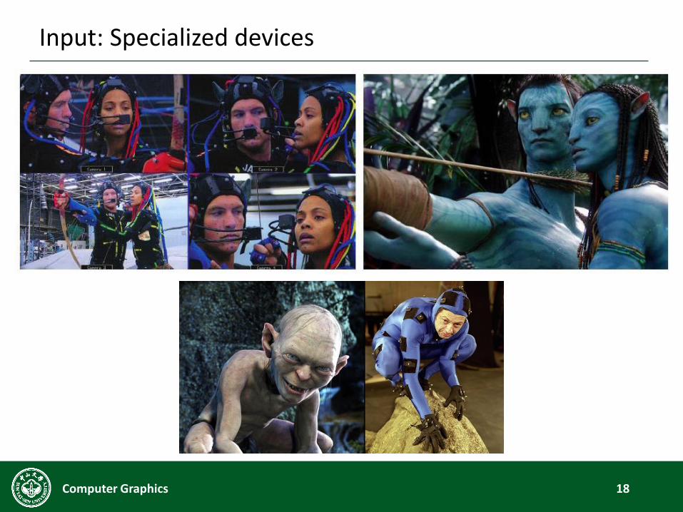
Input: Specialized devices
18Computer Graphics

What about the output device?
19Computer Graphics
Display Devices
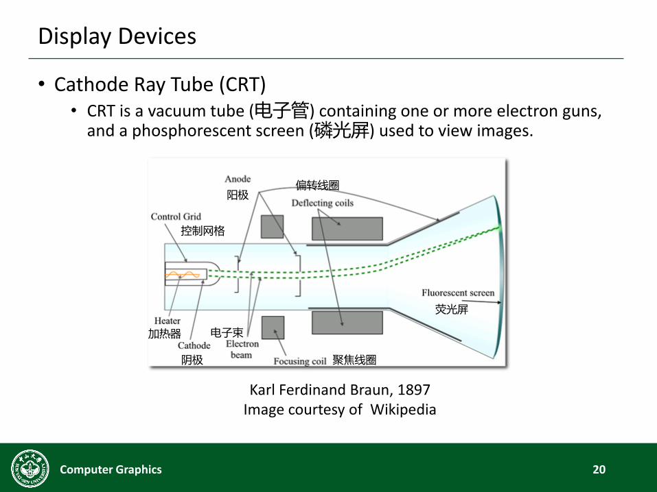
• Cathode Ray Tube (CRT)• CRT is a vacuum tube (电子管) containing one or more electron guns,
and a phosphorescent screen (磷光屏) used to view images.
20Computer Graphics
Karl Ferdinand Braun, 1897Image courtesy of Wikipedia
阳极偏转线圈
聚焦线圈
电子束
阴极
荧光屏
控制网格
加热器

Display Devices
• Vector Displays
21Computer Graphics
HP Oscilloscope
Asteroids, 1979 (行星游戏)
Star Wars, 1983 (星球大战)
Display Devices
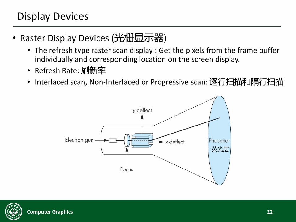
• Raster Display Devices (光栅显示器)• The refresh type raster scan display : Get the pixels from the frame buffer
individually and corresponding location on the screen display.
• Refresh Rate: 刷新率
• Interlaced scan, Non-Interlaced or Progressive scan: 逐行扫描和隔行扫描
22Computer Graphics
荧光层
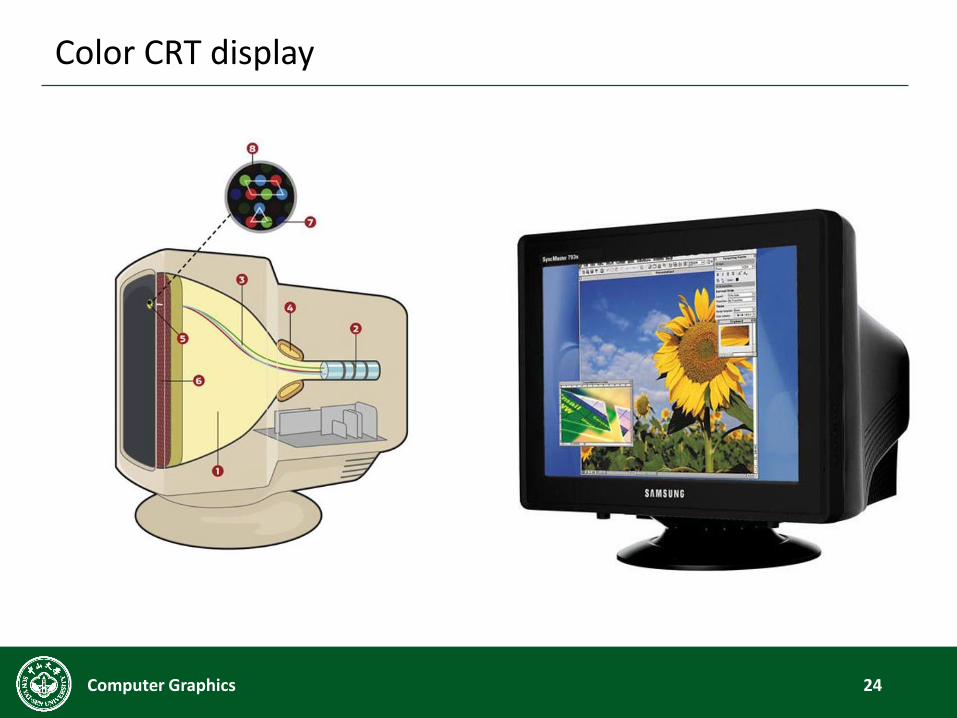
Color CRT display
23Computer Graphics
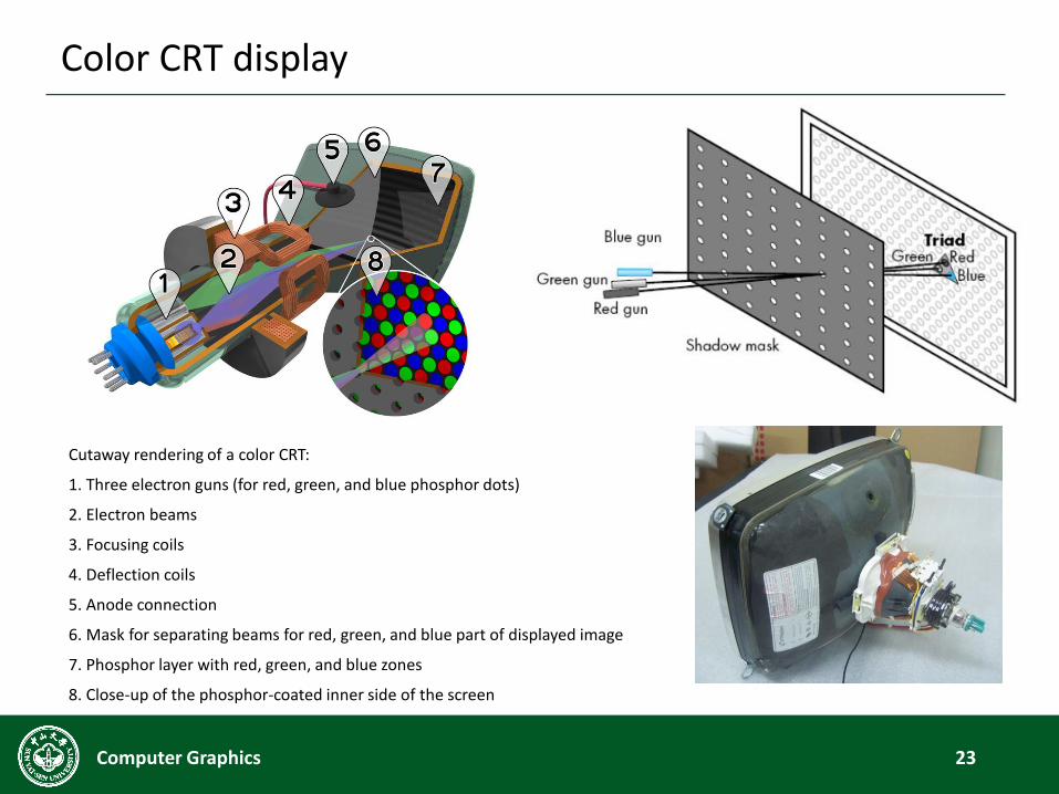
Cutaway rendering of a color CRT:
1. Three electron guns (for red, green, and blue phosphor dots)
2. Electron beams
3. Focusing coils
4. Deflection coils
5. Anode connection
6. Mask for separating beams for red, green, and blue part of displayed image
7. Phosphor layer with red, green, and blue zones
8. Close-up of the phosphor-coated inner side of the screen
Color CRT display
24Computer Graphics
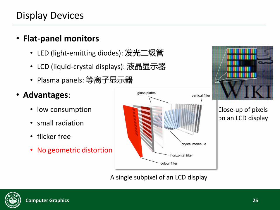
A single subpixel of an LCD display
• Flat-panel monitors
• LED (light-emitting diodes): 发光二级管
• LCD (liquid-crystal displays): 液晶显示器
• Plasma panels: 等离子显示器
• Advantages:
• low consumption
• small radiation
• flicker free
• No geometric distortion
Display Devices
25Computer Graphics
Close-up of pixels on an LCD display
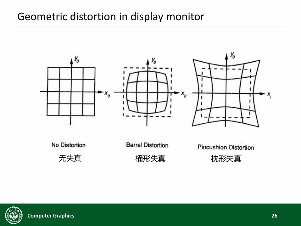
Geometric distortion in display monitor
26Computer Graphics
枕形失真桶形失真无失真
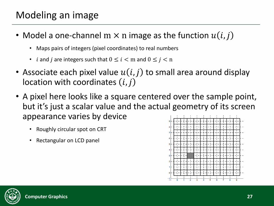
Modeling an image
• Model a one-channel m× n image as the function 𝑢 𝑖, 𝑗
• Maps pairs of integers (pixel coordinates) to real numbers
• 𝑖 and 𝑗 are integers such that 0 ≤ 𝑖 < m and 0 ≤ 𝑗 < n
• Associate each pixel value 𝑢 𝑖, 𝑗 to small area around display location with coordinates 𝑖, 𝑗
• A pixel here looks like a square centered over the sample point, but it’s just a scalar value and the actual geometry of its screen appearance varies by device
• Roughly circular spot on CRT
• Rectangular on LCD panel
27Computer Graphics
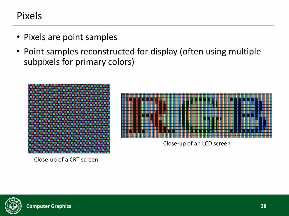
Pixels
• Pixels are point samples
• Point samples reconstructed for display (often using multiple subpixels for primary colors)
28Computer Graphics
Close-up of a CRT screen
Close-up of an LCD screen
Frame buffer
• Frame buffer (帧缓冲区): a buffer that stores the contents of
an image pixel by pixel
• Resolution (分辨率): the number of pixels per square inch on a
computer-generated display
• Rasterization (光栅化)
• Graphics Processing Units (GPU, 图形处理器)
29Computer Graphics
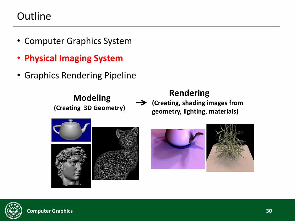
Outline
• Computer Graphics System
• Physical Imaging System
• Graphics Rendering Pipeline
30Computer Graphics
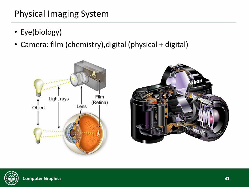
Physical Imaging System
• Eye(biology)
• Camera: film (chemistry),digital (physical + digital)
31Computer Graphics
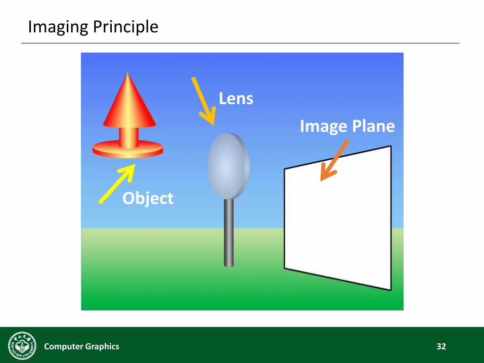
Imaging Principle
32Computer Graphics
Lens
Object
Image Plane
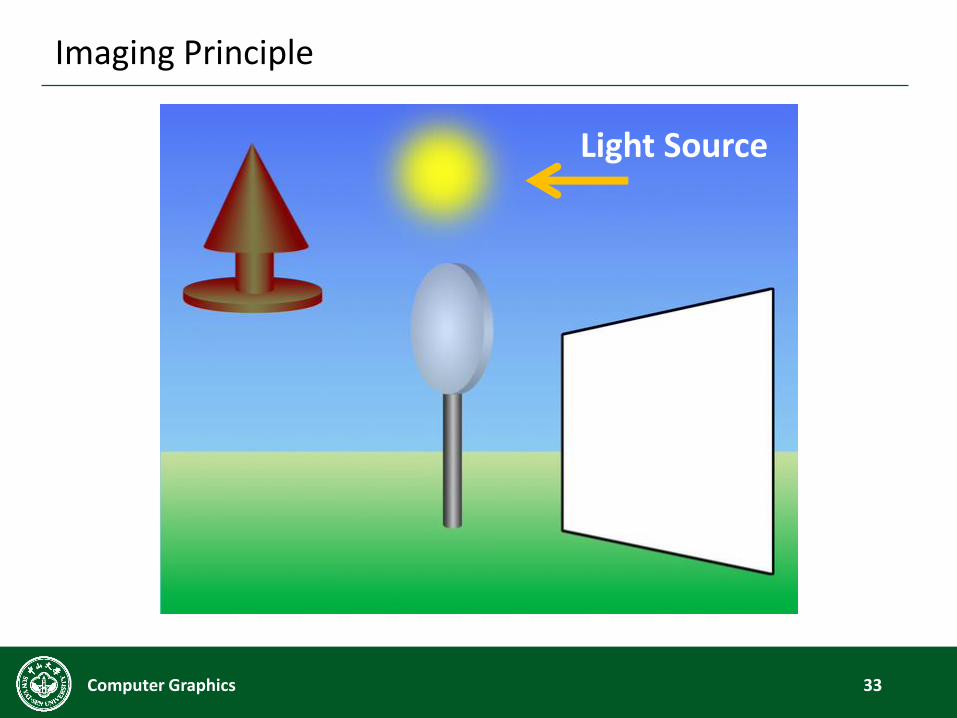
Imaging Principle
33Computer Graphics
Light Source
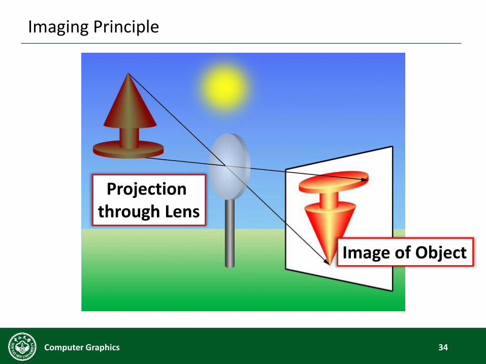
Imaging Principle
34Computer Graphics
Image of Object
Projection through Lens
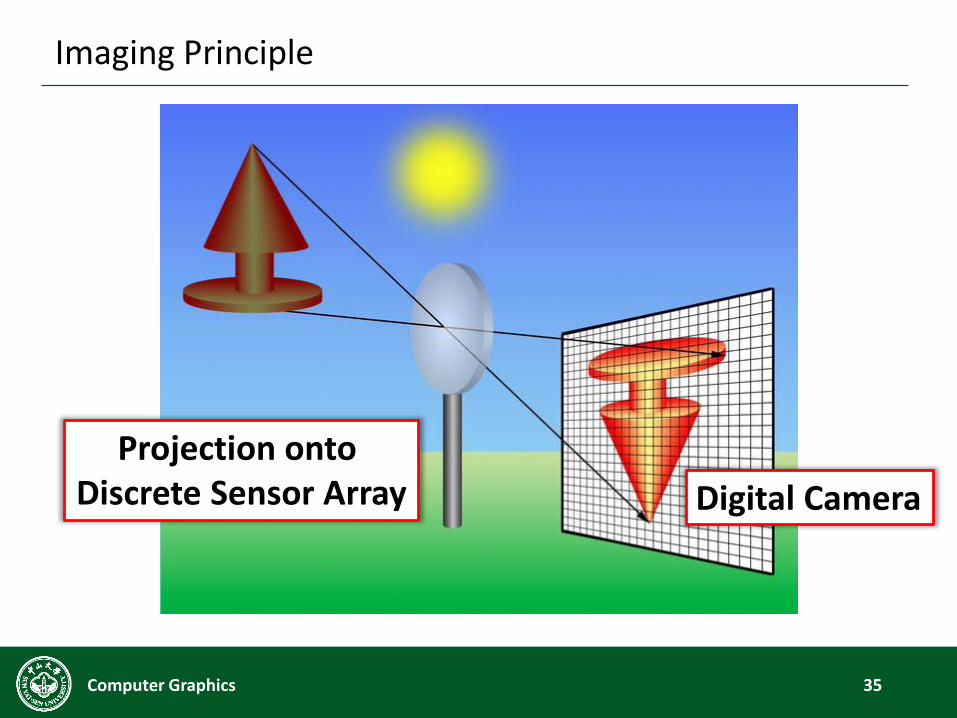
Imaging Principle
35Computer Graphics
Digital Camera
Projection onto Discrete Sensor Array
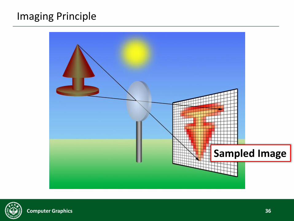
Imaging Principle
36Computer Graphics
Sampled Image

Digital Image
37Computer Graphics
ColorImage
GreyImage

Color Space
38Computer Graphics
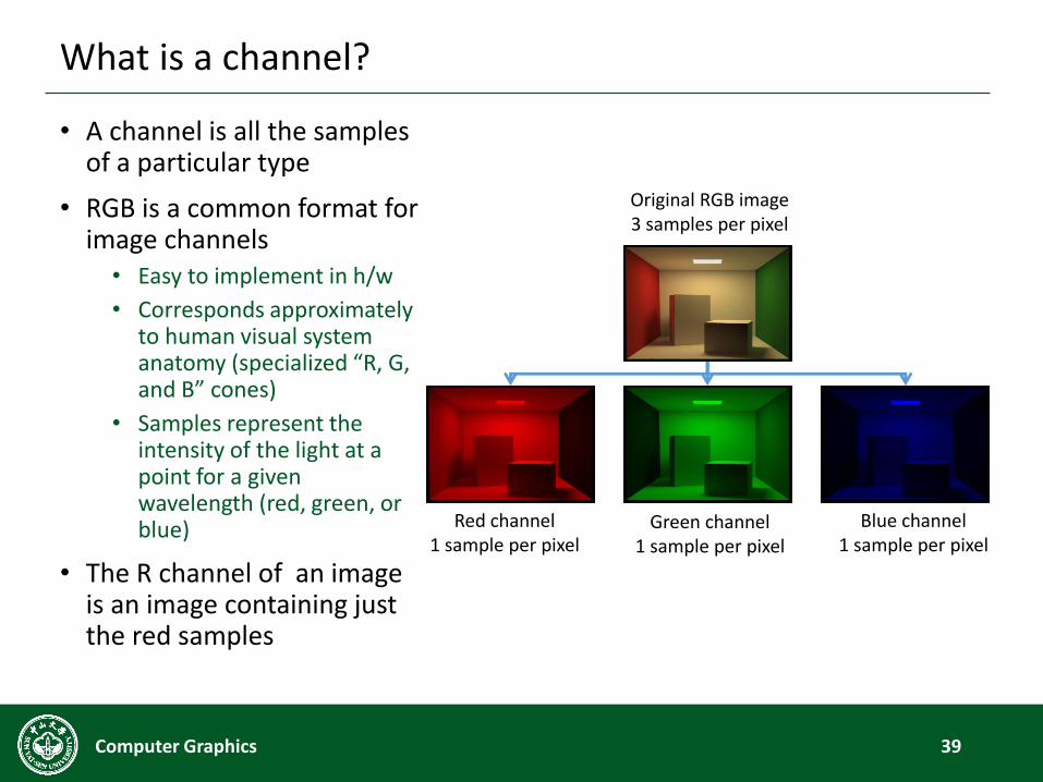
What is a channel?
• A channel is all the samples of a particular type
• RGB is a common format for image channels
• Easy to implement in h/w
• Corresponds approximately to human visual system anatomy (specialized “R, G, and B” cones)
• Samples represent the intensity of the light at a point for a given wavelength (red, green, or blue)
• The R channel of an image is an image containing just the red samples
39Computer Graphics
Original RGB image3 samples per pixel
Red channel1 sample per pixel
Blue channel1 sample per pixel
Green channel1 sample per pixel
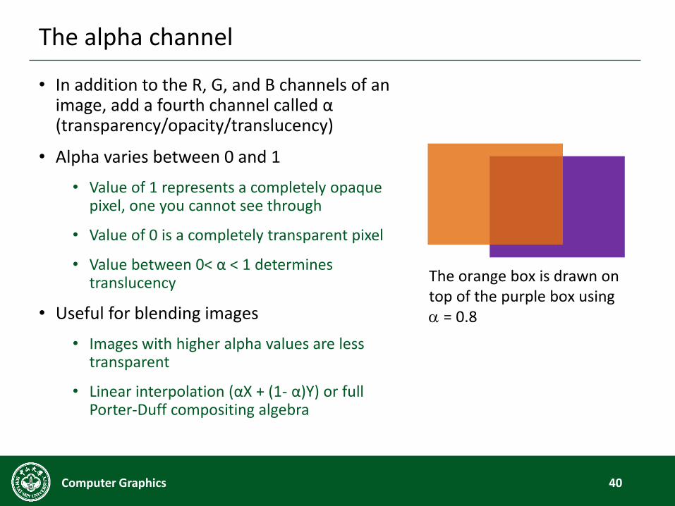
The alpha channel
• In addition to the R, G, and B channels of an image, add a fourth channel called α (transparency/opacity/translucency)
• Alpha varies between 0 and 1
• Value of 1 represents a completely opaque pixel, one you cannot see through
• Value of 0 is a completely transparent pixel
• Value between 0< α < 1 determines translucency
• Useful for blending images
• Images with higher alpha values are less transparent
• Linear interpolation (αX + (1- α)Y) or full Porter-Duff compositing algebra
40Computer Graphics
The orange box is drawn on top of the purple box using = 0.8
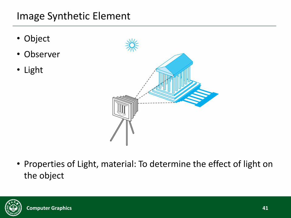
Image Synthetic Element
• Object
• Observer
• Light
• Properties of Light, material: To determine the effect of light on the object
41Computer Graphics
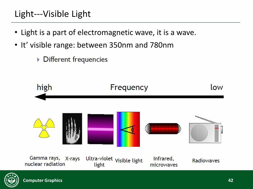
Light---Visible Light
• Light is a part of electromagnetic wave, it is a wave.
• It’ visible range: between 350nm and 780nm
42Computer Graphics
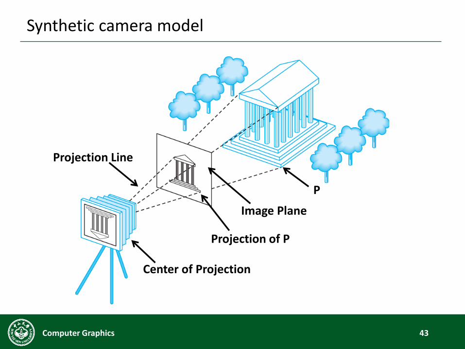
Synthetic camera model
43Computer Graphics
Image Plane
Center of Projection
Projection Line
Projection of P
P
Advantages of Synthetic camera model
• Object (物体), Observer (观察者) and light (光源) is complete
independent
• 2D graphics is a special case of 3D
• Easy to implement by API
• Set the properties of light, camera and material.
• To determine the results of image by API.
• Quick hardware implement is supported :OpenGL, Direct 3D etc.
is based on this model.
44Computer Graphics
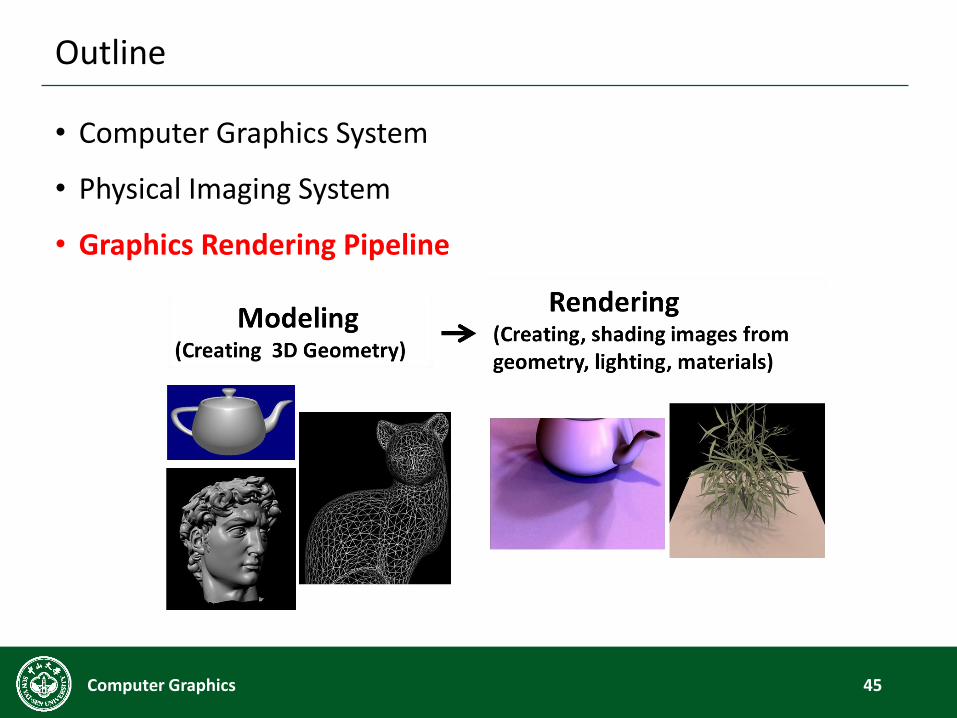
Outline
• Computer Graphics System
• Physical Imaging System
• Graphics Rendering Pipeline
45Computer Graphics
Demo - World War Z
46Computer Graphics
Graphics Rendering Pipeline
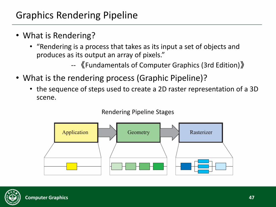
• What is Rendering?• “Rendering is a process that takes as its input a set of objects and
produces as its output an array of pixels.”
--《Fundamentals of Computer Graphics (3rd Edition)》
• What is the rendering process (Graphic Pipeline)?• the sequence of steps used to create a 2D raster representation of a 3D
scene.
47Computer Graphics
Rendering Pipeline Stages
Rendering Pipeline Stages
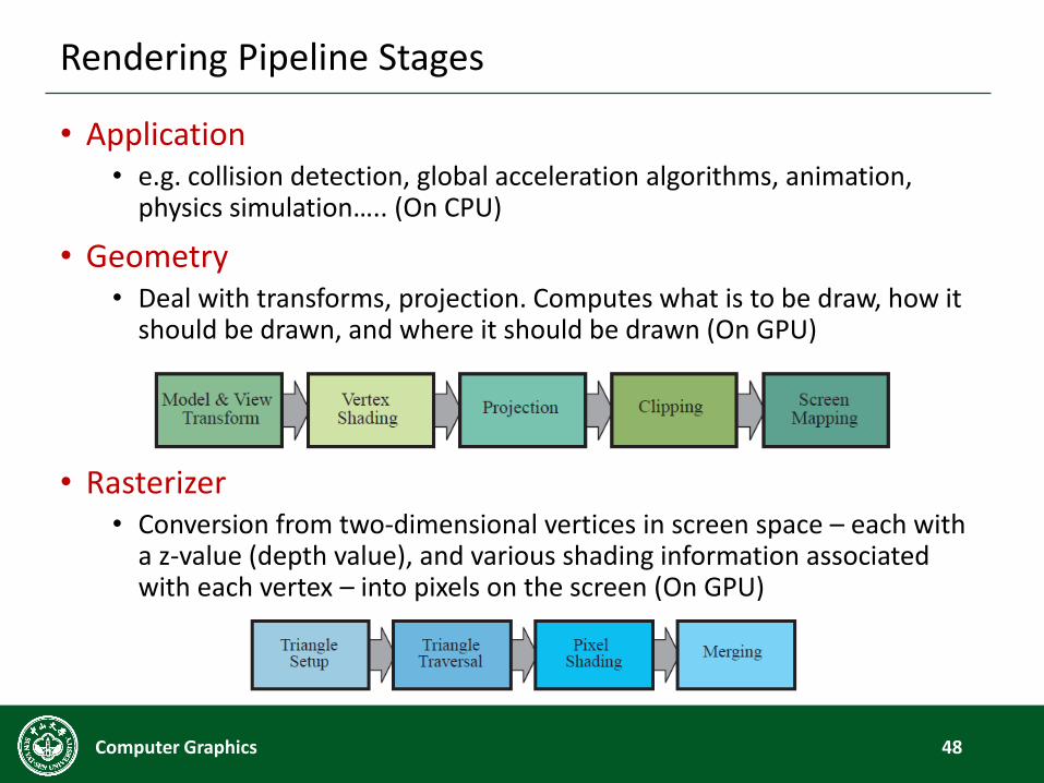
• Application• e.g. collision detection, global acceleration algorithms, animation,
physics simulation….. (On CPU)
• Geometry• Deal with transforms, projection. Computes what is to be draw, how it
should be drawn, and where it should be drawn (On GPU)
• Rasterizer• Conversion from two-dimensional vertices in screen space – each with
a z-value (depth value), and various shading information associated with each vertex – into pixels on the screen (On GPU)
48Computer Graphics
Rendering Pipeline
• Abstract model
• sequence of operations to transform geometric model into digital image
• graphics hardware workflow
• Underlying API model for programming graphics hardware
• OpenGL
• Direct 3D
• Many actual implementations
49Computer Graphics
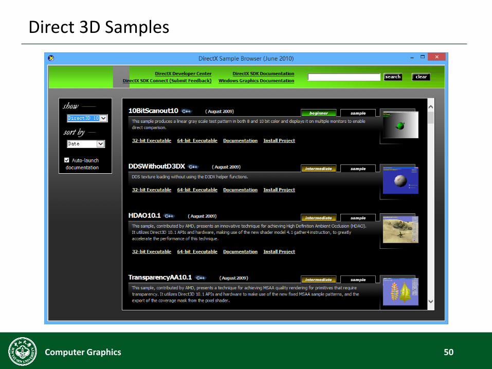
Direct 3D Samples
50Computer Graphics
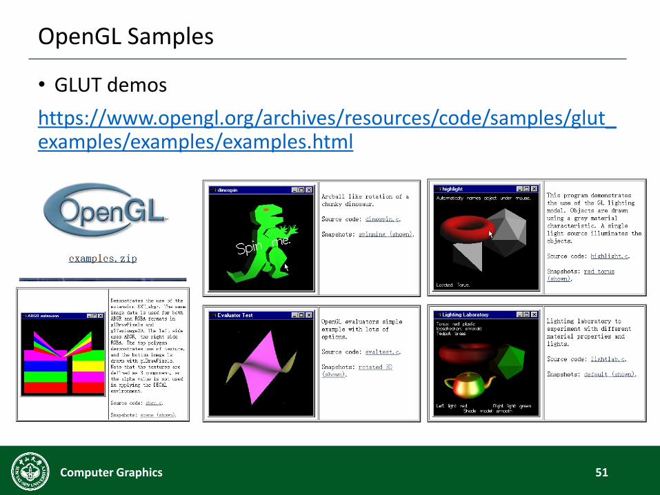
OpenGL Samples
• GLUT demos
https://www.opengl.org/archives/resources/code/samples/glut_examples/examples/examples.html
51Computer Graphics
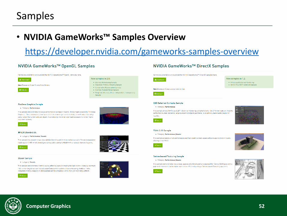
Samples
• NVIDIA GameWorks™ Samples Overview
https://developer.nvidia.com/gameworks-samples-overview
52Computer Graphics
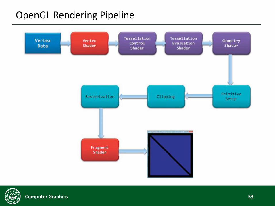
OpenGL Rendering Pipeline
53Computer Graphics
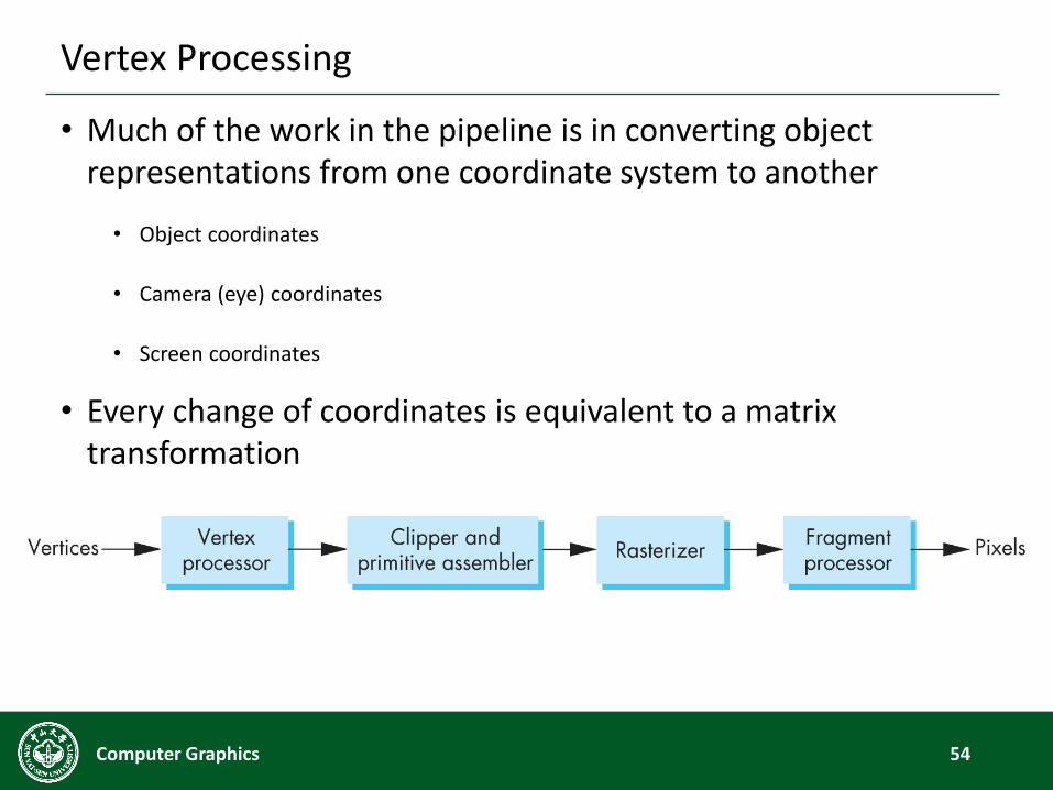
Vertex Processing
• Much of the work in the pipeline is in converting object representations from one coordinate system to another
• Object coordinates
• Camera (eye) coordinates
• Screen coordinates
• Every change of coordinates is equivalent to a matrix transformation
54Computer Graphics
Vertex Processing
55Computer Graphics
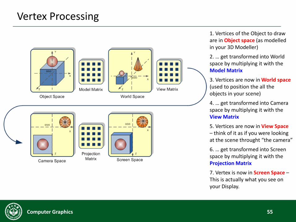
1. Vertices of the Object to draw are in Object space (as modelledin your 3D Modeller)
2. … get transformed into World space by multiplying it with the Model Matrix
3. Vertices are now in World space(used to position the all the objects in your scene)
4. … get transformed into Camera space by multiplying it with the View Matrix
5. Vertices are now in View Space– think of it as if you were looking at the scene throught “the camera”
6. … get transformed into Screen space by multiplying it with the Projection Matrix
7. Vertex is now in Screen Space –This is actually what you see on your Display.
Geometric Primitives
56Computer Graphics
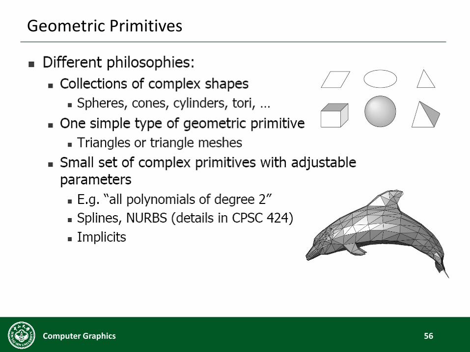
Geometric Primitives
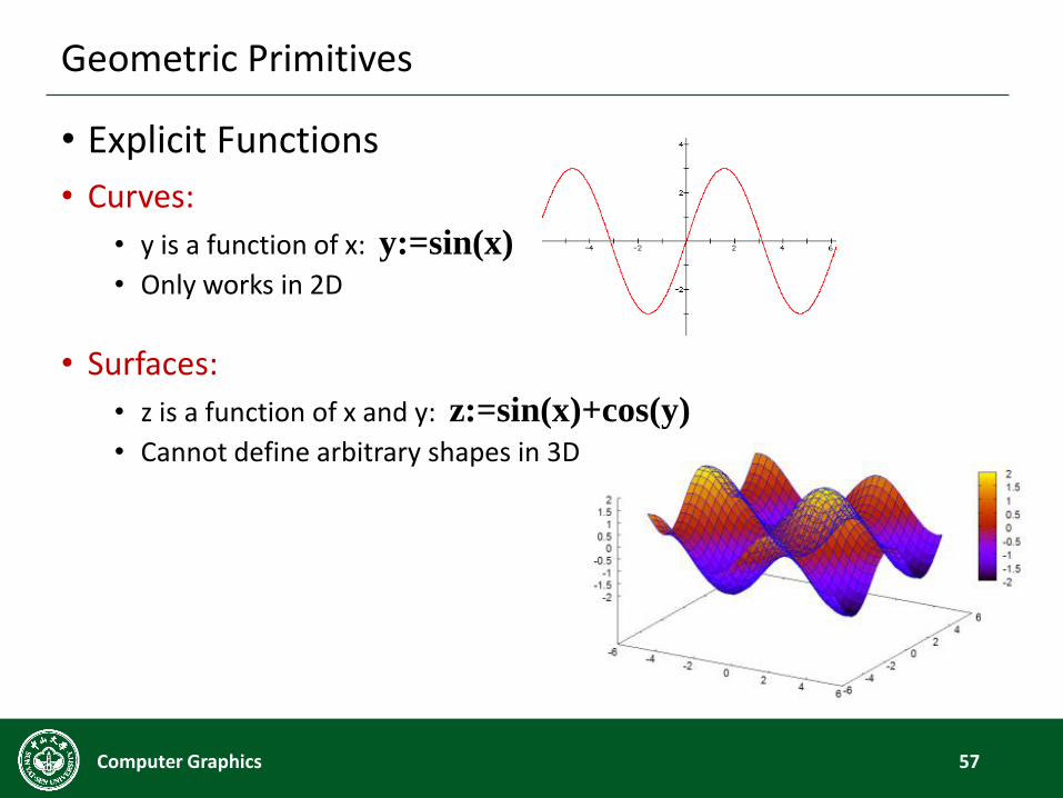
• Explicit Functions
• Curves:
• y is a function of x: y:=sin(x)
• Only works in 2D
• Surfaces:
• z is a function of x and y: z:=sin(x)+cos(y)
• Cannot define arbitrary shapes in 3D
57Computer Graphics
Geometric Primitives
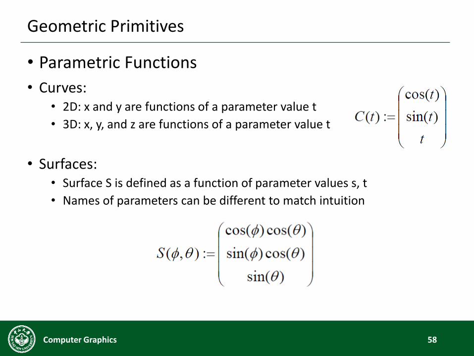
• Parametric Functions
• Curves:• 2D: x and y are functions of a parameter value t
• 3D: x, y, and z are functions of a parameter value t
• Surfaces:• Surface S is defined as a function of parameter values s, t
• Names of parameters can be different to match intuition
58Computer Graphics
Geometric Primitives
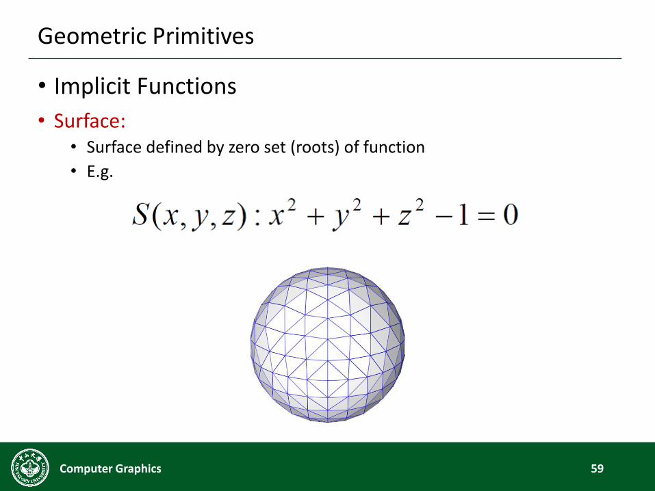
• Implicit Functions
• Surface:• Surface defined by zero set (roots) of function
• E.g.
59Computer Graphics
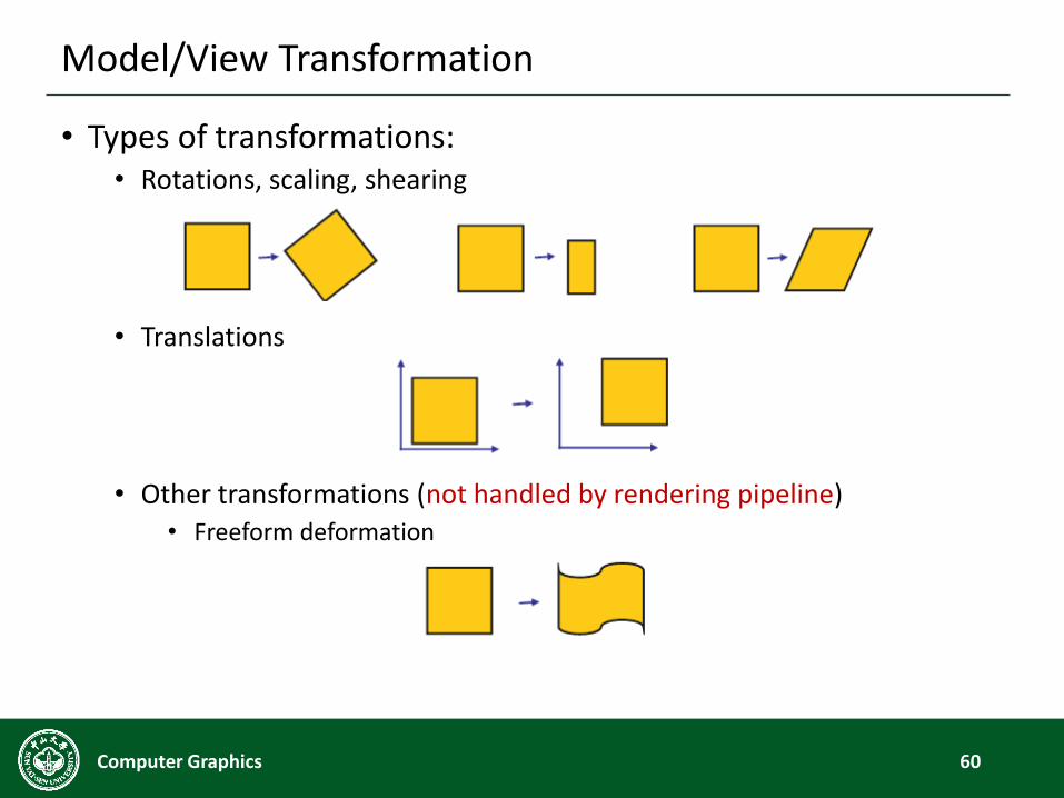
Model/View Transformation
• Types of transformations:• Rotations, scaling, shearing
• Translations
• Other transformations (not handled by rendering pipeline)• Freeform deformation
60Computer Graphics
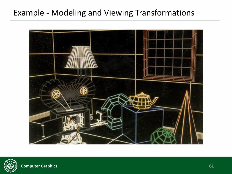
Example - Modeling and Viewing Transformations
61Computer Graphics
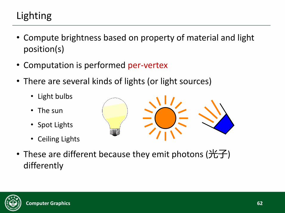
Lighting
• Compute brightness based on property of material and light position(s)
• Computation is performed per-vertex
• There are several kinds of lights (or light sources)
• Light bulbs
• The sun
• Spot Lights
• Ceiling Lights
• These are different because they emit photons (光子) differently
62Computer Graphics
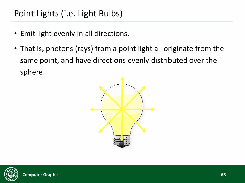
Point Lights (i.e. Light Bulbs)
• Emit light evenly in all directions.
• That is, photons (rays) from a point light all originate from the
same point, and have directions evenly distributed over the
sphere.
63Computer Graphics

Directional Lights (i.e. the Sun)
• Point light sources at an infinite (or near infinite) distance.
• Can assume that all rays are parallel.
64Computer Graphics
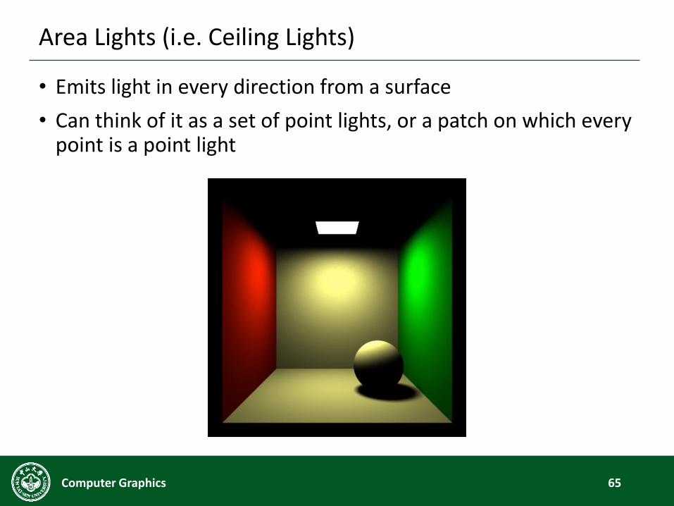
Area Lights (i.e. Ceiling Lights)
• Emits light in every direction from a surface
• Can think of it as a set of point lights, or a patch on which every point is a point light
65Computer Graphics
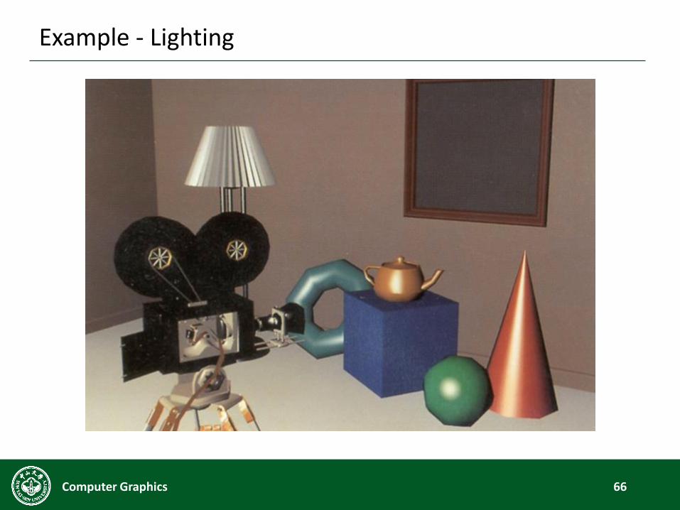
Example - Lighting
66Computer Graphics
Shading
67Computer Graphics
• Problem: How do we determine the color of a piece of
geometry?
• In the real world, color depends on the object’s surface color
and the color of the light.
• It is the same way in computer graphics.
• “Shading” is the process by which color is assigned to geometry.
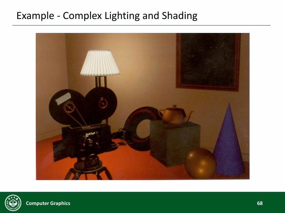
Example - Complex Lighting and Shading
68Computer Graphics
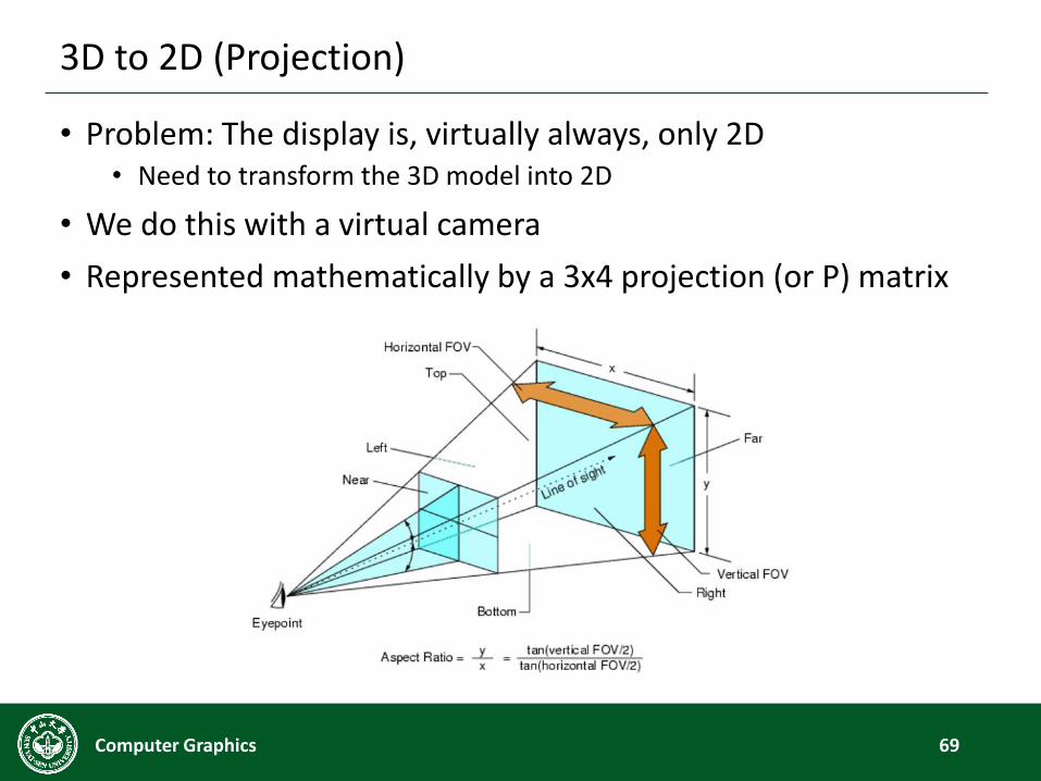
3D to 2D (Projection)
• Problem: The display is, virtually always, only 2D• Need to transform the 3D model into 2D
• We do this with a virtual camera
• Represented mathematically by a 3x4 projection (or P) matrix
69Computer Graphics
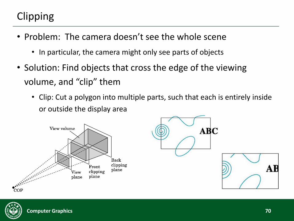
Clipping
• Problem: The camera doesn’t see the whole scene
• In particular, the camera might only see parts of objects
• Solution: Find objects that cross the edge of the viewing
volume, and “clip” them
• Clip: Cut a polygon into multiple parts, such that each is entirely inside
or outside the display area
70Computer Graphics
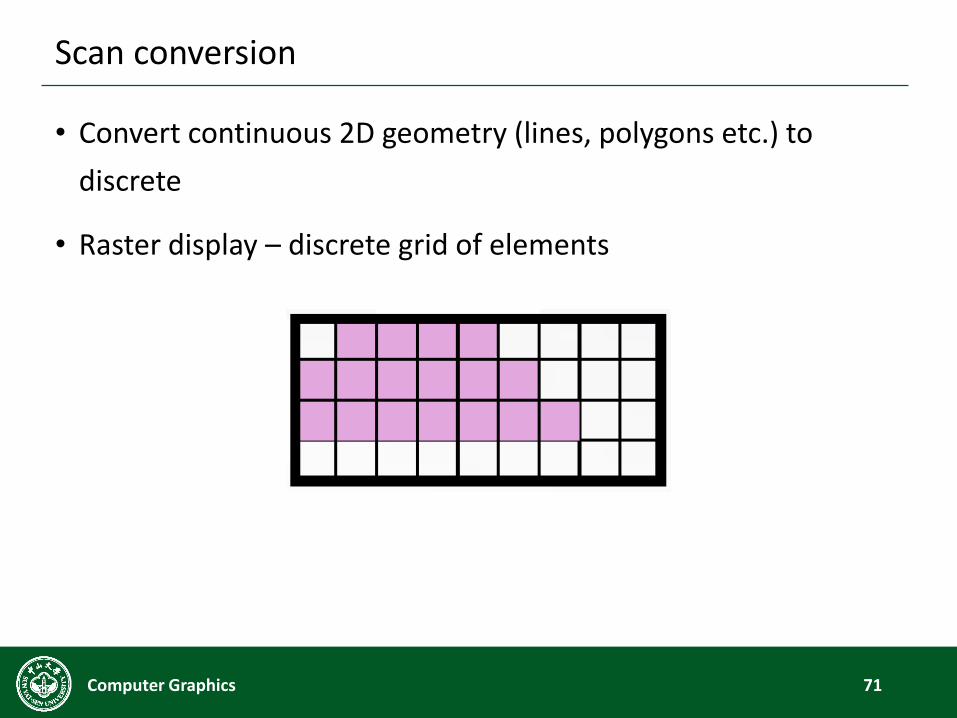
Scan conversion
• Convert continuous 2D geometry (lines, polygons etc.) to
discrete
• Raster display – discrete grid of elements
71Computer Graphics
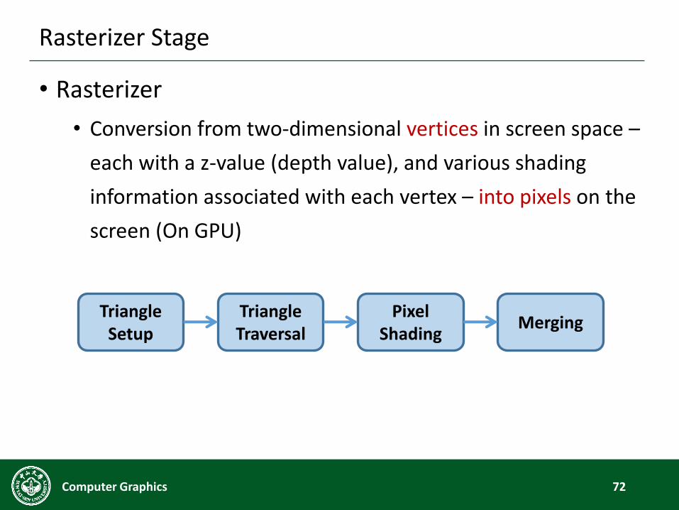
Rasterizer Stage
• Rasterizer
• Conversion from two-dimensional vertices in screen space –
each with a z-value (depth value), and various shading
information associated with each vertex – into pixels on the
screen (On GPU)
72Computer Graphics
TriangleSetup
TriangleTraversal
MergingPixel
Shading
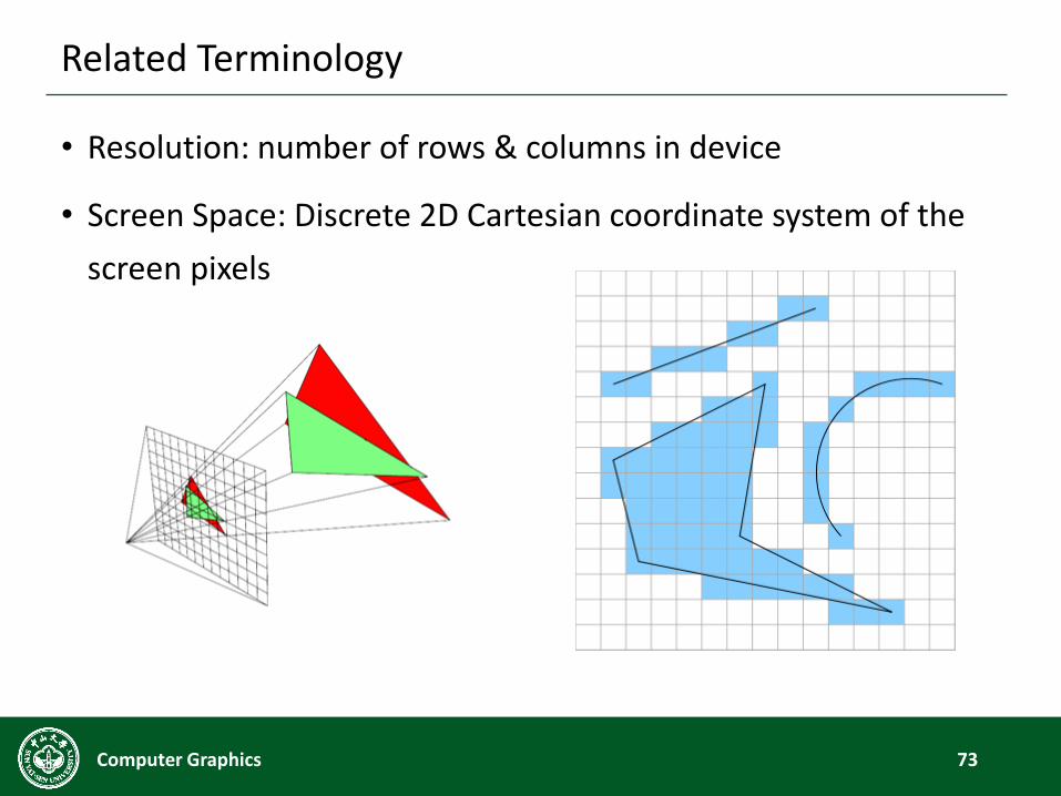
Related Terminology
• Resolution: number of rows & columns in device
• Screen Space: Discrete 2D Cartesian coordinate system of the
screen pixels
73Computer Graphics
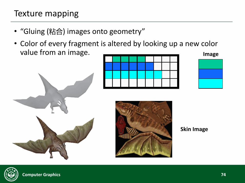
Texture mapping
• “Gluing (粘合) images onto geometry”
• Color of every fragment is altered by looking up a new color value from an image.
74Computer Graphics
Image
Skin Image
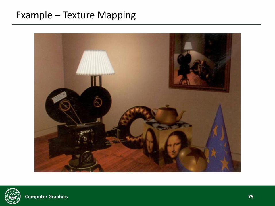
Example – Texture Mapping
75Computer Graphics
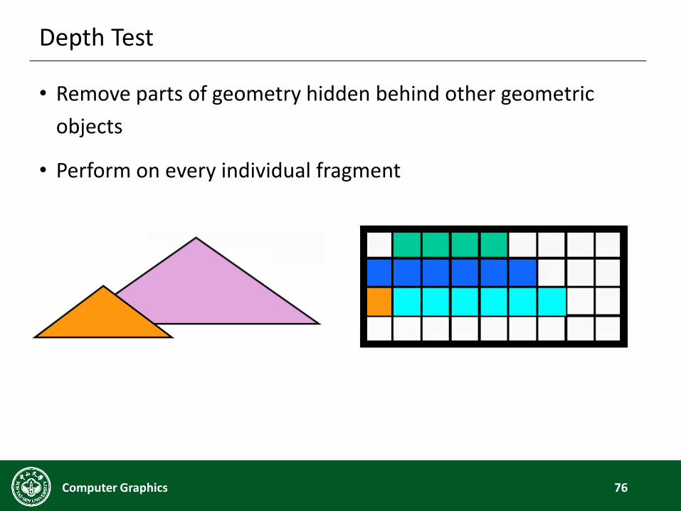
Depth Test
• Remove parts of geometry hidden behind other geometric
objects
• Perform on every individual fragment
76Computer Graphics
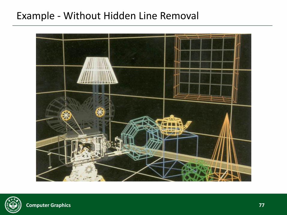
Example - Without Hidden Line Removal
77Computer Graphics
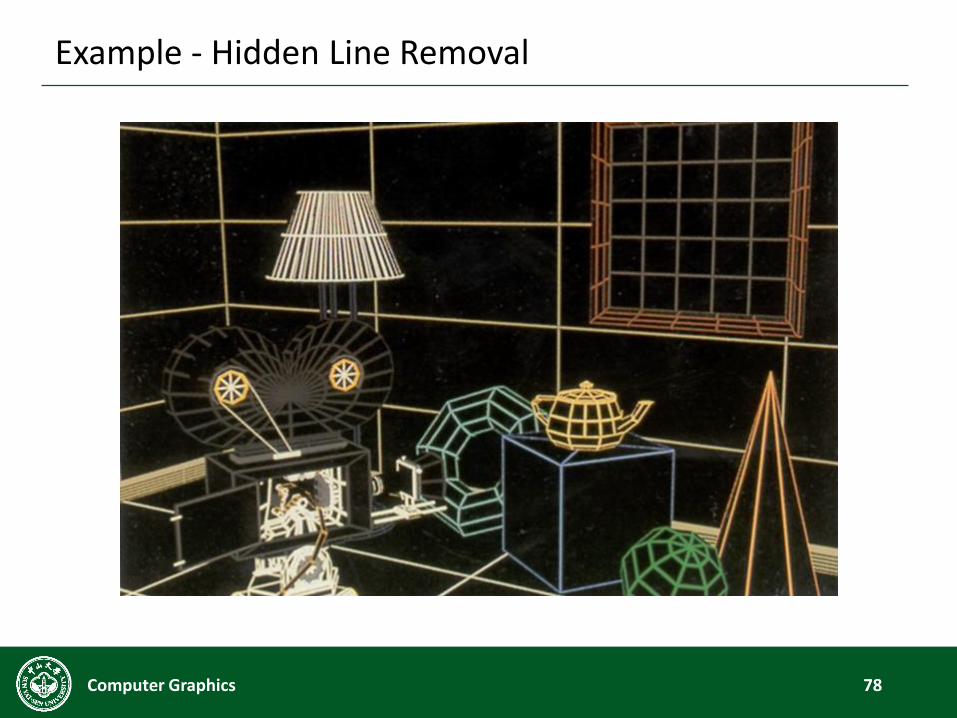
Example - Hidden Line Removal
78Computer Graphics
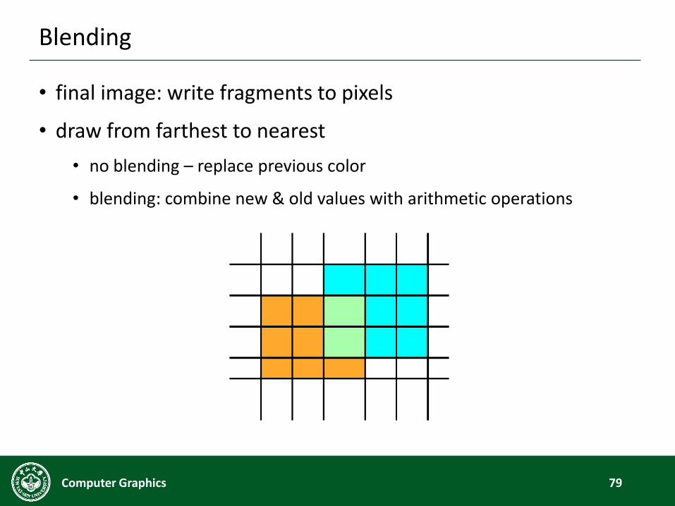
Blending
• final image: write fragments to pixels
• draw from farthest to nearest
• no blending – replace previous color
• blending: combine new & old values with arithmetic operations
79Computer Graphics
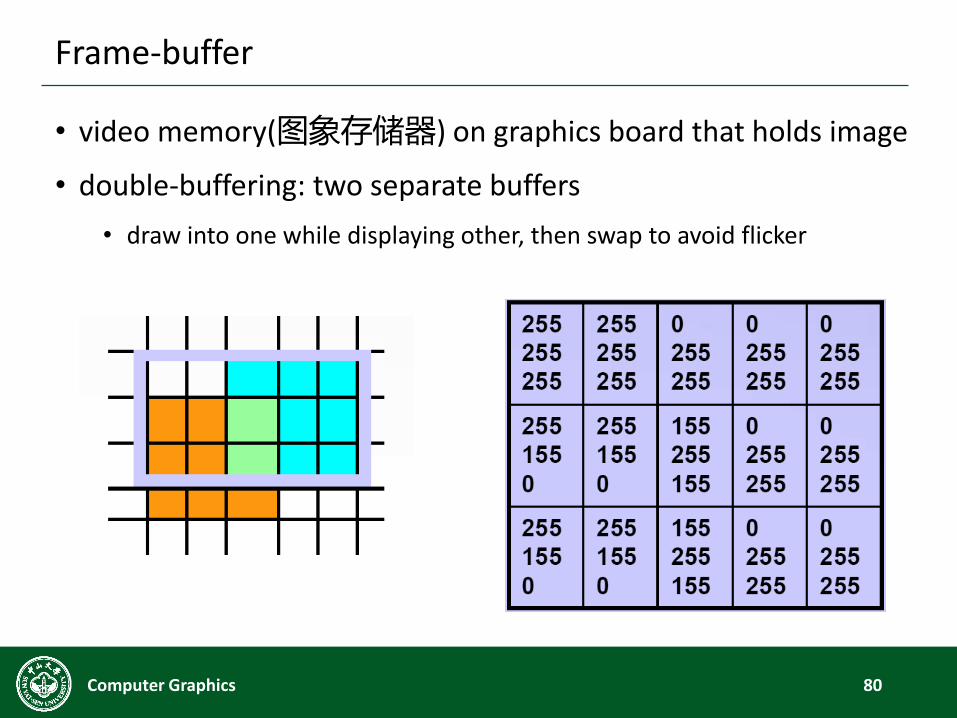
Frame-buffer
• video memory(图象存储器) on graphics board that holds image
• double-buffering: two separate buffers
• draw into one while displaying other, then swap to avoid flicker
80Computer Graphics
Modeling vs. Rendering
81Computer Graphics
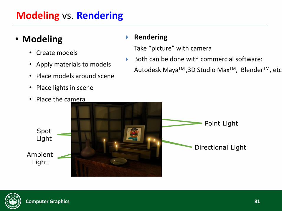
• Modeling• Create models
• Apply materials to models
• Place models around scene
• Place lights in scene
• Place the camera
Directional LightAmbient
Light
Point Light
Spot Light
Rendering
Take “picture” with camera
Both can be done with commercial software:
Autodesk MayaTM ,3D Studio MaxTM, BlenderTM, etc.
Summary
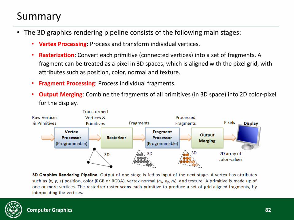
• The 3D graphics rendering pipeline consists of the following main stages:
• Vertex Processing: Process and transform individual vertices.
• Rasterization: Convert each primitive (connected vertices) into a set of fragments. A
fragment can be treated as a pixel in 3D spaces, which is aligned with the pixel grid, with
attributes such as position, color, normal and texture.
• Fragment Processing: Process individual fragments.
• Output Merging: Combine the fragments of all primitives (in 3D space) into 2D color-pixel
for the display.
82Computer Graphics
Recommended