A composite manufacturing process
for producing Class A finished components References
92
The main sources used for this document are indicated below. At the time of publication, the
editions indicated were valid. All standards are subject to revision, and parties to
agreements based on this document are encouraged to investigate the possibility of applying
the most recent editions of the standards indicated below:
3M, 2011. Technical data sheet for the Growth Market car. [Online] Available at: http://www.visteon.com/innovate/growthmarket/pdfs/3M_Paint_Protection_Film.pdf [Accessed 10 November 2013].
AWR., n.d. A.W.R. Smith Process Instrumentation cc. [Online] Available at: http://www.instruments.co.za/Catalog/Surface%20Roughness%20Tester.htm [Accessed 10 November 2013].
Aiken, D. & Aiken, Z. 2012. Fibre glass repair polyester or epoxy. 2nd ed. Atglen, PA: Schiffer Publishing, Ltd.
AMT Composites, 2013. AMT composites. [Online] Available at: http://www.amtcomposites.co.za/ [Accessed 10 November 2013].
Argotec, 2008-2013. The clear choice, why polyurethane. [Online] Available at: http://www.argotec.com/P_WhyPolyurethane.html [Accessed 10 November 2013].
AVS, Opencart, 2013. Auto vinyl solutions. [Online] Available at: http://autovinylsolutions.com/3M_1080/Gloss_White_Vinyl_Wrap [Accessed 10 November 2013].
Babin, P. n.d. Working with acrylic. [Online] Available at: http://www.bcae1.com/plexi.htm [Accessed 10 November 2013].
Berg, P. 2013. POPULAR MECHANICS, How to vinyl-wrap a car. [Online] Available at: http://www.popularmechanics.com/cars/how-to/repair/how-to-vinyl-wrap-a-car#slide-1 [Accessed 10 November 2013].
Campbell, F. 2004. Manufacturing processes for advanced composites. Oxford: Elsevier Advanced Technology.
Canning, W. 1982. The Canning handbook: surface finishing technology. 23rd ed. New York: W. Canning plc. Birmingham.
Catia, 2012. Catia Tutor, your best way to learn Catia V5. [Online] Available at: http://catiatutor.com/Basic/CATIA-Handbook/class-a-surfacing.html
A composite manufacturing process
for producing Class A finished components References
93
[Accessed 10 November 2013].
Clubkit clearcote, n.d. Clubkit clearcote. [Online] Available at: http://www.clubkitclearcote.com/instructions/Howtomake%20a%20fiberglass%20mold.pdf [Accessed 10 November 2013].
CNC cookbook, n.d. CNC cookbook software and information for machinist. [Online] Available at: http://www.cnccookbook.com/CCCNCMillFeedsSpeeds.htm [Accessed 10 November 2013].
Coetzee, G. 2013. Jonker Sailplanes 10day production cycle [Interview] (4 October 2013). Notes in possession of the author of this dissertation.
Degarmo, E.P., Black, J.T. & Kohser, R.A., 2003. Materials and processes in manufacturing (9th ed.). In: s.l.:Wiley, p. 223.
Dirks, W. 2012. DG Flugzeugbau GmbH. [Online] Available at: http://dg-flugzeugbau.de/pur-lack-e.html [Accessed 10 November 2013].
DME. 2013. Plastic University, Mold Technology Series. [Online] Available at: http://www.dmeuniversity.net/english/c5.cfm?index=1 [Accessed 10 November 2013]. Duffy, J. 2004. Auto body repair technology. 4th ed. New York: Thomson, Delmar Learning. Farlex, Inc., 2012. The free dictionary. [Online] Available at: http://www.TheFreeDictionary.com/ [Accessed 10 November 2013].
Fibreglass Warehouse, 2013. Learning centre, gelcoat application and preparation. [Online] Available at: https://www.fiberglasswarehouse.com/gelcoat_application.php [Accessed 10 November 2013].
Fibreglast, 2012. Plug surface preparation and mold surface maintenance. [Online] Available at: http://www.fibreglast.com/product/plug-surface-preparation-and-mold-surface-maintenance [Accessed 10 November 2013].
Gaunle, K. 2012. ehow-Surface Finish Specifications. [Online] Available at: http://www.ehow.com/list_7684300_surface-finish-specifications.html [Accessed 10 November 2013].
GlasCraft. 2012. GlasCraft. [Online] Available at: http://www.glascraft.co.uk/product.asp?catid=76&prodid=560 [Accessed 10 November 2013].
Gliding Federation of Australia. 2001. Chapter 3: Basic theory. In: Basic gliding knowledge. Victoria, Australia: The Gliding Federation of Australia, p. 130.
A composite manufacturing process
for producing Class A finished components References
94
Haddock, R. 2002. Paint finishes for metal. Metalmag. March/April 2002. [Online] Available at: http://www.metalcoaters.com/pdf/AtoZPrt3_reprint.pdf [Accessed 20 May 2014] H&M. 2011. H&M Houtbewerkingsmasjiene. [Online] Available at: http://h-m.nl/index.php?lang=nl-NL [Accessed 10 November 2013].
Höchsmann GmbH, 2007-2013 . Höchsmann, technology for wood. [Online] Available at: http://www.hoechsmann.com/index.php?module=16&category=1&fbID=11345&lang=en [Accessed 10 November 2013].
James Town Distributers, 2008. MEKP Liquid hardener. [Online] Available at: http://www.jamestowndistributors.com/userportal/show_product.do?pid=2084 [Accessed 10 November 2013].
Jones, R. 2006-2007. One piece fibre glass mold construction. [Online] Available at: http://www.fiberglassmoldmanual.com/ [Accessed 10 November 2013].
Jonker, A. 2003. Laminate analysis of composite materials. Potchefstroom, SA: NWU, Mechanical Engineering.
Julie, Z. Joseph, C. & Kirby, E., 2006. Surface roughness optimisation in an end-milling operation using the taguchi design method. Journal of Material Processing Technology.
Kirchoff, H, 2011. ehow - SPI mold finish standards. [Online] Available at: http://www.ehow.com/info_12214752_spi-mold-finish-standards.html [Accessed 10 November 2013].
Lion-Cachet, B., 2013. AMT composites, Infusion tooling process for high temperature processing [Interview] (March 2013). (Notes in possession of the author of the dissertation) Lion-Cachet, B., 2013. Zyvax - Mould release philosophy and application presentation. Johannesburg: AMT Composites.
LLC. 2013. Dictionary.com. [Online] Available at: http://m.dictionary.com/ [Accessed 10 November 2013].
MacKenzie, D. 2008. Metrology centre, surface texture measurement fundamentals, technical seminar, metrology center open house. [Online] Available at: http://www.metrologycenter.com/Open%20House/Surface%20Texture%20Measurement%20Fundamentals%20For%20Metrology%20Center%20Open%20House.pdf [Accessed 10 November 2013].
Mike, S., Caleb, M. & Li, D. 1998-1999. Surface Roughness prediction technique for CNC end-milling. Journal of Industrial Technology, Volume 15(1):bladsynommers.
A composite manufacturing process
for producing Class A finished components References
95
Mjet, 2006. Grafiwrap vehicle wrapping system. [Online] Available at: http://www.sesoma.lv/sites/sesoma.lv/files/Grafiwrap-Spec.pdf [Accessed 10 November 2013].
Morena, J. 1994. Advanced composite mould making. Malabar, Florida: Krieger Publishing Company. NGCC, 2013. Network group for composites in construction, Glossary. [Online] Available at: http://www.ngcc.org.uk/Information/Introduction/Glossary.aspx [Accessed 10 November 2013].
Paint Shield, n.d. Automotive protection specialists. [Online] Available at: http://www.paintshield-china.com/en/paint-protection-film-101.php [Accessed 10 November 2013].
Pandey, P., 2004. Composite material, web based course. [Online] Available at: http://ecourses.vtu.ac.in/nptel/courses/Webcourse-contents/IISc-BANG/Composite%20Materials/Learning%20material%20-%20composite%20material.pdf [Accessed 10 November 2013].
Perspex SA, n.d. Perspex South Africa, acrylic sheet information manual. [Online] Available at: http://www.perspex.co.za/Uploads/TechnicalManual/663ACRYLIC%20SHEET%20INFORMATION-COMPLETE.pdf [Accessed 10 November 2013].
Pilkington, 2009. Pilkington plateau. [Online] Available at: http://www.pilkington.com/assetmanager_ws/fileserver.aspx?cmd=get_file&file_id=1008&digest=Hr0z66OF19XN3gkbZu611w==&ct=pdf [Accessed 10 November 2013].
Raja, M., November, 2005. Experimental optimization of process parameters to obtain class a surface finish in resin transfer moulding process. Montreal: Doctorial Thesis, Department of Mechanical Engineering, McGill University.
Rapp, P., 2002. Surface roughness & conversion tables. In: Engineers black book. 2nd Ed. Perth, Western Australia: Pat Rapp Enterprises, p. 150.
Rashid, M. & Abdul Lani, M., 2010. Surface roughness prediction for cnc milling process using artificial neural network. World Congress on Engineering 2010, Vol III, WCE.
SP systems, 2013. AMTcomposites, guide to composites. the advantages of epoxy resin versus polyester in marine composite structures. [Online] Available at: http://www.amtcomposites.co.za/sites/default/files/media/howto/Advantages%20of%20Epoxy%20over%20Polyester.pdf [Accessed 10 November 2013].
SPAREPARTS, 2012. Pistonheads. [Online] Available at: http://www.pistonheads.com/gassing/topic.asp?t=1125982 [Accessed 10 November 2013].
A composite manufacturing process
for producing Class A finished components References
96
Standox, 2008. Standox. [Online] Available at: http://www.standox.co.za/ [Accessed 10 November 2013].
Sunbelt Materials, 1998. Sunbelt materials. [Online] Available at: http://www.sunbeltmaterials.com/clicoat_intro.htm [Accessed 10 November 2013].
Sutherland, J., 2009. The John W. Sutherland research page. [Online] Available at: http://www.mfg.mtu.edu/cyberman/quality/metrology/surface.html [Accessed 10 November 2013].
The Eastwood company, 2013. Eastwood do the right job. [Online] Available at: http://eastwood.com/1k-coating-vs-2k-coatings [Accessed 10 November 2013].
The mold polishing Co. Inc., 2012. The mold polishing Co. Inc.. [Online] Available at: http://www.moldpolishing.com/FinishingGuide.htm [Accessed 10 November 2013].
TIA 1, Technology Innovation Association, 2011-2012. Standard workshop practise 13 composite repairs. TIA. Available at Potchefstroom: Jonker Sailplanes
TIA 2, Technoligy innovation association, 2011-2012. Standard workshop practise 28 spraying facilities. TIA. Available at Potchefstroom: Jonker Sailplanes
TIA 3, Technoligy innovation association, 2011-2012. Standard workshop practise 29 Spraying Facilities. TIA. Available at Potchefstroom: Jonker Sailplanes
TIA 4, Technoligy innovation association, 2011-2012. Standard workshop practise 36 release agents. TIA. Available at Potchefstroom: Jonker Sailplanes
TIA 5, Technoligy innovation association, 2011-2012. Standard workshop practise 41 composite tooling. TIA. Available at Potchefstroom: Jonker Sailplanes
TIA 6, Technoligy innovation association, 2011-2012. Standard workshop practise 50 glossary. TIA. Available at Potchefstroom: Jonker Sailplanes
TIA 5, Technoligy innovation association, 2011-2012. Standard workshop practise 10 composite repairs. TIA. Available at Potchefstroom: Jonker Sailplanes
Trotec, n.d. Laser, Marking, cutting, engraving. [Online] Available at: www.troteclaser.com [Accessed 10 November 2013].
VISI, n.d. VISI. [Online] Available at: http://www.visicadcam.com/products [Accessed 10 November 2013].
VPS, 2012. Vehicle protection shield. [Online] Available at: http://www.vpsprotection.co.za/Aviation_Home/aviation_home.html [Accessed 10 November 2013].

A composite manufacturing process
for producing Class A finished components References
97
Wanberg, 2009. Composite materials fabriction handbook #1. Stillwater: Wolfgang Publications Inc.
Wanberg, 2012. Composite materials fabrication handbook #2. Stillwater: Wolfgang Publications Inc.
A composite manufacturing process
for producing Class A finished components
APPENDIX A:
Factory Mould Survey Data
A1
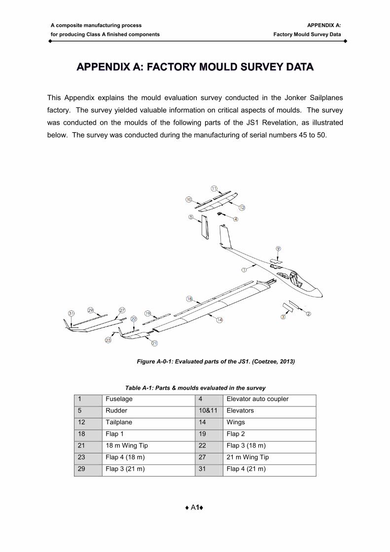
This Appendix explains the mould evaluation survey conducted in the Jonker Sailplanes
factory. The survey yielded valuable information on critical aspects of moulds. The survey
was conducted on the moulds of the following parts of the JS1 Revelation, as illustrated
below. The survey was conducted during the manufacturing of serial numbers 45 to 50.
Table A-1: Parts & moulds evaluated in the survey
1 Fuselage 4 Elevator auto coupler
5 Rudder 10&11 Elevators
12 Tailplane 14 Wings
18 Flap 1 19 Flap 2
21 18 m Wing Tip 22 Flap 3 (18 m)
23 Flap 4 (18 m) 27 21 m Wing Tip
29 Flap 3 (21 m) 31 Flap 4 (21 m)
Figure A-0-1: Evaluated parts of the JS1. (Coetzee, 2013)
A composite manufacturing process
for producing Class A finished components
APPENDIX A:
Factory Mould Survey Data
A2
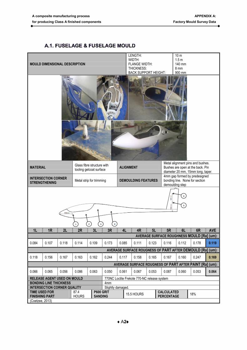
MOULD DIMENSIONAL DESCRIPTION
LENGTH: WIDTH: FLANGE WIDTH: THICKNESS: BACK SUPPORT HEIGHT:
10 m 1.5 m 140 mm 8 mm 900 mm
MATERIAL Glass fibre structure with tooling gelcoat surface
ALIGNMENT Metal alignment pins and bushes. Bushes are open at the back. Pin diameter 20 mm, 15mm long, taper.
INTERSECTION CORNER STRENGTHENING
Metal strip for trimming DEMOULDING FEATURES 4mm gap formed by predesigned bonding line. None for section demoulding step
1L 1R 2L 2R 3L 3R 4L 4R 5L 5R 6L 6R AVE
AVERAGE SURFACE ROUGHNESS MOULD [Ra] (um):
0.084 0.107 0.118 0.114 0.109 0.173 0.085 0.111 0.123 0.116 0.112 0.178 0.119
AVERAGE SURFACE ROUGNESS OF PART AFTER DEMOULD [Ra] (um):
0.118 0.156 0.167 0.163 0.162 0.244 0.117 0.158 0.165 0.167 0.160 0.247 0.169
AVERAGE SURFACE ROUGNESS OF PART AFTER PAINT [Ra] (um):
0.066 0.065 0.056 0.086 0.063 0.050 0.061 0.067 0.053 0.087 0.060 0.053 0.064
RELEASE AGENT USED ON MOULD 770NC Loctite Frekote 770-NC release system
BONDING LINE THICKNESS 4mm
INTERSECTION CORNER QUALITY Slightly damaged.
TIME USED FOR FINISHING PART
87.4 HOURS
P600 GRIT SANDING
15.5 HOURS CALCULATED PERCENTAGE
18%
(Coetzee, 2013)
A composite manufacturing process
for producing Class A finished components
APPENDIX A:
Factory Mould Survey Data
A3
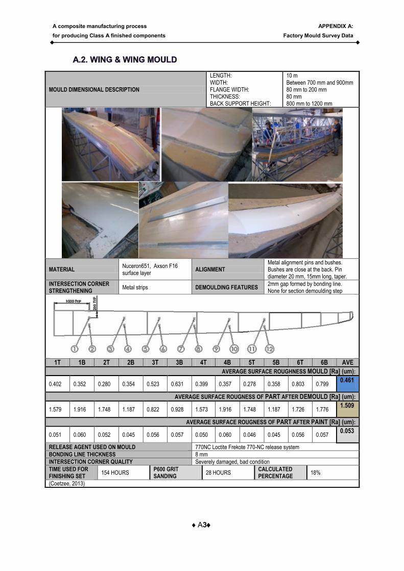
MOULD DIMENSIONAL DESCRIPTION
LENGTH: WIDTH: FLANGE WIDTH: THICKNESS: BACK SUPPORT HEIGHT:
10 m Between 700 mm and 900mm 80 mm to 200 mm 80 mm 800 mm to 1200 mm
MATERIAL Nuceron651, Axson F16 surface layer
ALIGNMENT Metal alignment pins and bushes. Bushes are close at the back. Pin diameter 20 mm, 15mm long, taper.
INTERSECTION CORNER STRENGTHENING
Metal strips DEMOULDING FEATURES 2mm gap formed by bonding line. None for section demoulding step
1T 1B 2T 2B 3T 3B 4T 4B 5T 5B 6T 6B AVE
AVERAGE SURFACE ROUGHNESS MOULD [Ra] (um):
0.402 0.352 0.280 0.354 0.523 0.631 0.399 0.357 0.278 0.358 0.803 0.799 0.461
AVERAGE SURFACE ROUGNESS OF PART AFTER DEMOULD [Ra] (um):
1.579 1.916 1.748 1.187 0.822 0.928 1.573 1.916 1.748 1.187 1.726 1.776 1.509
AVERAGE SURFACE ROUGNESS OF PART AFTER PAINT [Ra] (um):
0.051 0.060 0.052 0.045 0.056 0.057 0.050 0.060 0.046 0.045 0.056 0.057 0.053
RELEASE AGENT USED ON MOULD 770NC Loctite Frekote 770-NC release system
BONDING LINE THICKNESS 8 mm
INTERSECTION CORNER QUALITY Severely damaged, bad condition
TIME USED FOR FINISHING SET
154 HOURS P600 GRIT SANDING
28 HOURS CALCULATED PERCENTAGE
18%
(Coetzee, 2013)
A composite manufacturing process
for producing Class A finished components
APPENDIX A:
Factory Mould Survey Data
A4
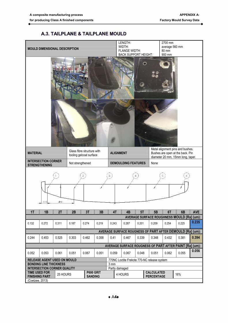
MOULD DIMENSIONAL DESCRIPTION
LENGTH: WIDTH: FLANGE WIDTH: BACK SUPPORT HEIGHT:
2700 mm average 560 mm 80 mm 900 mm
MATERIAL Glass fibre structure with tooling gelcoat surface
ALIGNMENT Metal alignment pins and bushes. Bushes are open at the back. Pin diameter 20 mm, 15mm long, taper.
INTERSECTION CORNER STRENGTHENING
Not strengthened DEMOULDING FEATURES None
1T 1B 2T 2B 3T 3B 4T 4B 5T 5B 6T 6B AVE
AVERAGE SURFACE ROUGHNESS MOULD [Ra] (um):
0.132 0.272 0.311 0.187 0.274 0.219 0.243 0.287 0.201 0.209 0.254 0.225 0.235
AVERAGE SURFACE ROUGNESS OF PART AFTER DEMOULD [Ra] (um):
0.244 0.453 0.525 0.303 0.462 0.358 0.41 0.467 0.339 0.348 0.432 0.381 0.394
AVERAGE SURFACE ROUGNESS OF PART AFTER PAINT [Ra] (um):
0.052 0.053 0.061 0.051 0.067 0.051 0.059 0.067 0.048 0.051 0.062 0.055 0.056
RELEASE AGENT USED ON MOULD 770NC Loctite Frekote 770-NC release system
BONDING LINE THICKNESS 3 mm
INTERSECTION CORNER QUALITY Partly damaged
TIME USED FOR FINISHING PART
25 HOURS P600 GRIT SANDING
4 HOURS CALCULATED PERCENTAGE
16%
(Coetzee, 2013)
A composite manufacturing process
for producing Class A finished components
APPENDIX A:
Factory Mould Survey Data
A5
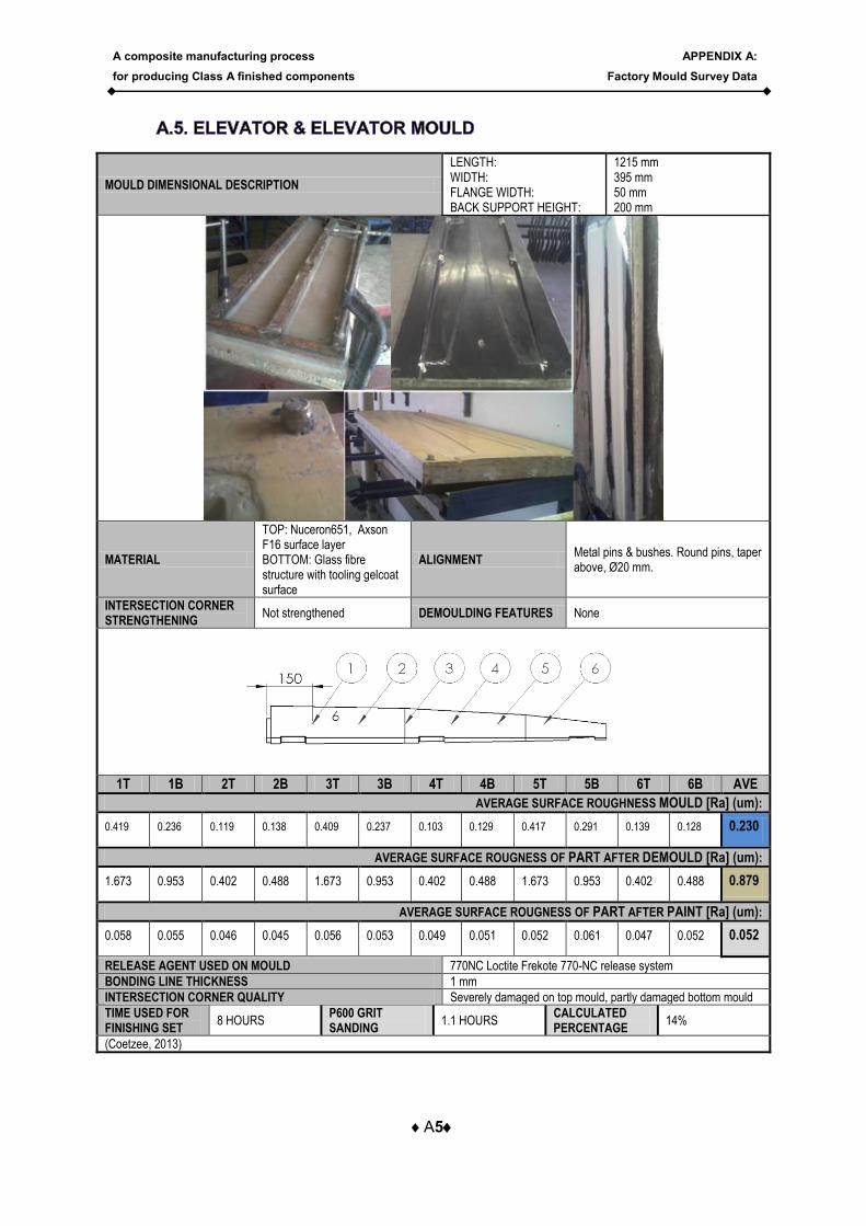
MOULD DIMENSIONAL DESCRIPTION
LENGTH: WIDTH: FLANGE WIDTH: BACK SUPPORT HEIGHT:
1215 mm 395 mm 50 mm 200 mm
MATERIAL
TOP: Nuceron651, Axson F16 surface layer BOTTOM: Glass fibre structure with tooling gelcoat surface
ALIGNMENT Metal pins & bushes. Round pins, taper above, Ø20 mm.
INTERSECTION CORNER STRENGTHENING
Not strengthened DEMOULDING FEATURES None
1T 1B 2T 2B 3T 3B 4T 4B 5T 5B 6T 6B AVE
AVERAGE SURFACE ROUGHNESS MOULD [Ra] (um):
0.419 0.236 0.119 0.138 0.409 0.237 0.103 0.129 0.417 0.291 0.139 0.128 0.230
AVERAGE SURFACE ROUGNESS OF PART AFTER DEMOULD [Ra] (um):
1.673 0.953 0.402 0.488 1.673 0.953 0.402 0.488 1.673 0.953 0.402 0.488 0.879
AVERAGE SURFACE ROUGNESS OF PART AFTER PAINT [Ra] (um):
0.058 0.055 0.046 0.045 0.056 0.053 0.049 0.051 0.052 0.061 0.047 0.052 0.052
RELEASE AGENT USED ON MOULD 770NC Loctite Frekote 770-NC release system
BONDING LINE THICKNESS 1 mm
INTERSECTION CORNER QUALITY Severely damaged on top mould, partly damaged bottom mould
TIME USED FOR FINISHING SET
8 HOURS P600 GRIT SANDING
1.1 HOURS CALCULATED PERCENTAGE
14%
(Coetzee, 2013)
A composite manufacturing process
for producing Class A finished components
APPENDIX A:
Factory Mould Survey Data
A6
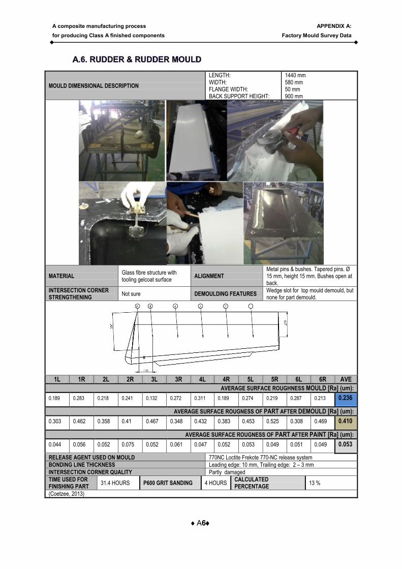
MOULD DIMENSIONAL DESCRIPTION
LENGTH: WIDTH: FLANGE WIDTH: BACK SUPPORT HEIGHT:
1440 mm 580 mm 50 mm 900 mm
MATERIAL Glass fibre structure with tooling gelcoat surface
ALIGNMENT Metal pins & bushes. Tapered pins. Ø 15 mm, height 15 mm. Bushes open at back.
INTERSECTION CORNER STRENGTHENING
Not sure DEMOULDING FEATURES Wedge slot for top mould demould, but none for part demould.
1L 1R 2L 2R 3L 3R 4L 4R 5L 5R 6L 6R AVE
AVERAGE SURFACE ROUGHNESS MOULD [Ra] (um):
0.189 0.283 0.218 0.241 0.132 0.272 0.311 0.189 0.274 0.219 0.287 0.213 0.236
AVERAGE SURFACE ROUGNESS OF PART AFTER DEMOULD [Ra] (um):
0.303 0.462 0.358 0.41 0.467 0.348 0.432 0.383 0.453 0.525 0.308 0.469 0.410
AVERAGE SURFACE ROUGNESS OF PART AFTER PAINT [Ra] (um):
0.044 0.056 0.052 0.075 0.052 0.061 0.047 0.052 0.053 0.049 0.051 0.049 0.053
RELEASE AGENT USED ON MOULD 770NC Loctite Frekote 770-NC release system
BONDING LINE THICKNESS Leading edge: 10 mm, Trailing edge: 2 – 3 mm
INTERSECTION CORNER QUALITY Partly damaged
TIME USED FOR FINISHING PART
31.4 HOURS P600 GRIT SANDING 4 HOURS CALCULATED PERCENTAGE
13 %
(Coetzee, 2013)
A composite manufacturing process
for producing Class A finished components
APPENDIX A:
Factory Mould Survey Data
A7
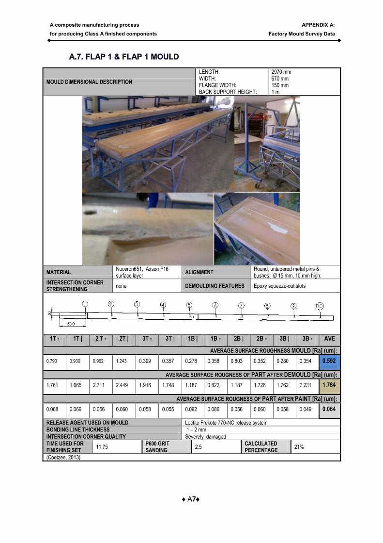
MOULD DIMENSIONAL DESCRIPTION
LENGTH: WIDTH: FLANGE WIDTH: BACK SUPPORT HEIGHT:
2970 mm 670 mm 150 mm 1 m
MATERIAL Nuceron651, Axson F16 surface layer
ALIGNMENT Round, untapered metal pins & bushes; Ø 15 mm, 10 mm high.
INTERSECTION CORNER STRENGTHENING
none DEMOULDING FEATURES Epoxy squeeze-out slots
1T - 1T | 2 T - 2T | 3T - 3T | 1B | 1B - 2B | 2B - 3B | 3B - AVE
AVERAGE SURFACE ROUGHNESS MOULD [Ra] (um):
0.790 0.930 0.962 1.243 0.399 0.357 0.278 0.358 0.803 0.352 0.280 0.354 0.592
AVERAGE SURFACE ROUGNESS OF PART AFTER DEMOULD [Ra] (um):
1.761 1.665 2.711 2.449 1.916 1.748 1.187 0.822 1.187 1.726 1.762 2.231 1.764
AVERAGE SURFACE ROUGNESS OF PART AFTER PAINT [Ra] (um):
0.068 0.069 0.056 0.060 0.058 0.055 0.092 0.086 0.056 0.060 0.058 0.049 0.064
RELEASE AGENT USED ON MOULD Loctite Frekote 770-NC release system
BONDING LINE THICKNESS 1 – 2 mm
INTERSECTION CORNER QUALITY Severely damaged
TIME USED FOR FINISHING SET
11.75 P600 GRIT SANDING
2.5 CALCULATED PERCENTAGE
21%
(Coetzee, 2013)
A composite manufacturing process
for producing Class A finished components
APPENDIX A:
Factory Mould Survey Data
A8
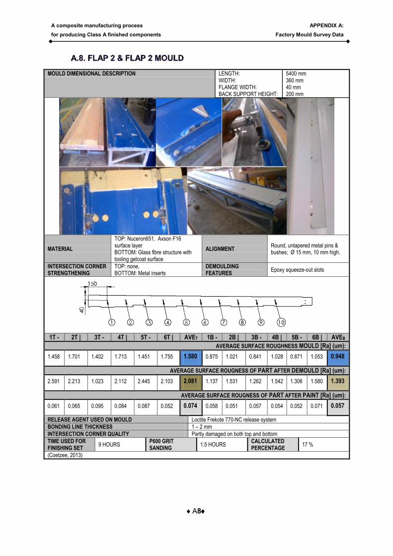
MOULD DIMENSIONAL DESCRIPTION LENGTH: WIDTH: FLANGE WIDTH: BACK SUPPORT HEIGHT:
5400 mm 360 mm 40 mm 200 mm
MATERIAL
TOP: Nuceron651, Axson F16 surface layer BOTTOM: Glass fibre structure with tooling gelcoat surface
ALIGNMENT Round, untapered metal pins & bushes; Ø 15 mm, 10 mm high.
INTERSECTION CORNER STRENGTHENING
TOP: none, BOTTOM: Metal inserts
DEMOULDING FEATURES
Epoxy squeeze-out slots
1T - 2T | 3T - 4T | 5T - 6T | AVET 1B - 2B | 3B - 4B | 5B - 6B | AVEB
AVERAGE SURFACE ROUGHNESS MOULD [Ra] (um):
1.458 1.701 1.402 1.713 1.451 1.755 1.580 0.875 1.021 0.841 1.028 0.871 1.053 0.948
AVERAGE SURFACE ROUGNESS OF PART AFTER DEMOULD [Ra] (um):
2.591 2.213 1.023 2.112 2.445 2.103 2.081 1.137 1.531 1.262 1.542 1.306 1.580 1.393
AVERAGE SURFACE ROUGNESS OF PART AFTER PAINT [Ra] (um):
0.061 0.065 0.095 0.084 0.087 0.052 0.074 0.058 0.051 0.057 0.054 0.052 0.071 0.057
RELEASE AGENT USED ON MOULD Loctite Frekote 770-NC release system
BONDING LINE THICKNESS 1 – 2 mm
INTERSECTION CORNER QUALITY Partly damaged on both top and bottom
TIME USED FOR FINISHING SET
9 HOURS P600 GRIT SANDING
1.5 HOURS CALCULATED PERCENTAGE
17 %
(Coetzee, 2013)
A composite manufacturing process
for producing Class A finished components
APPENDIX A:
Factory Mould Survey Data
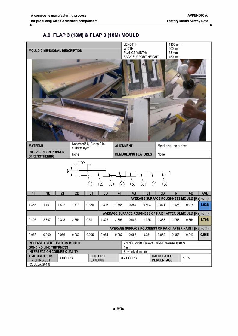
A9
MOULD DIMENSIONAL DESCRIPTION
LENGTH: WIDTH: FLANGE WIDTH: BACK SUPPORT HEIGHT:
1160 mm 200 mm 35 mm 150 mm
MATERIAL Nuceron651, Axson F16 surface layer
ALIGNMENT Metal pins, no bushes.
INTERSECTION CORNER STRENGTHENING
None DEMOULDING FEATURES None
1T 1B 2T 2B 3T 3B 4T 4B 5T 5B 6T 6B AVE
AVERAGE SURFACE ROUGHNESS MOULD [Ra] (um):
1.458 1.701 1.402 1.713 0.358 0.803 1.755 0.354 0.803 0.841 1.028 0.215 1.036
AVERAGE SURFACE ROUGNESS OF PART AFTER DEMOULD [Ra] (um):
2.406 2.807 2.313 2.354 0.591 1.325 2.896 0.985 1.325 1.388 1.753 0.354 1.708
AVERAGE SURFACE ROUGNESS OF PART AFTER PAINT [Ra] (um):
0.068 0.069 0.056 0.060 0.095 0.084 0.087 0.057 0.054 0.052 0.058 0.049 0.066
RELEASE AGENT USED ON MOULD 770NC Loctite Frekote 770-NC release system
BONDING LINE THICKNESS 1 mm
INTERSECTION CORNER QUALITY Severely damaged
TIME USED FOR FINISHING SET
4 HOURS P600 GRIT SANDING
0.7 HOURS CALCULATED PERCENTAGE
18 %
(Coetzee, 2013)
A composite manufacturing process
for producing Class A finished components
APPENDIX A:
Factory Mould Survey Data
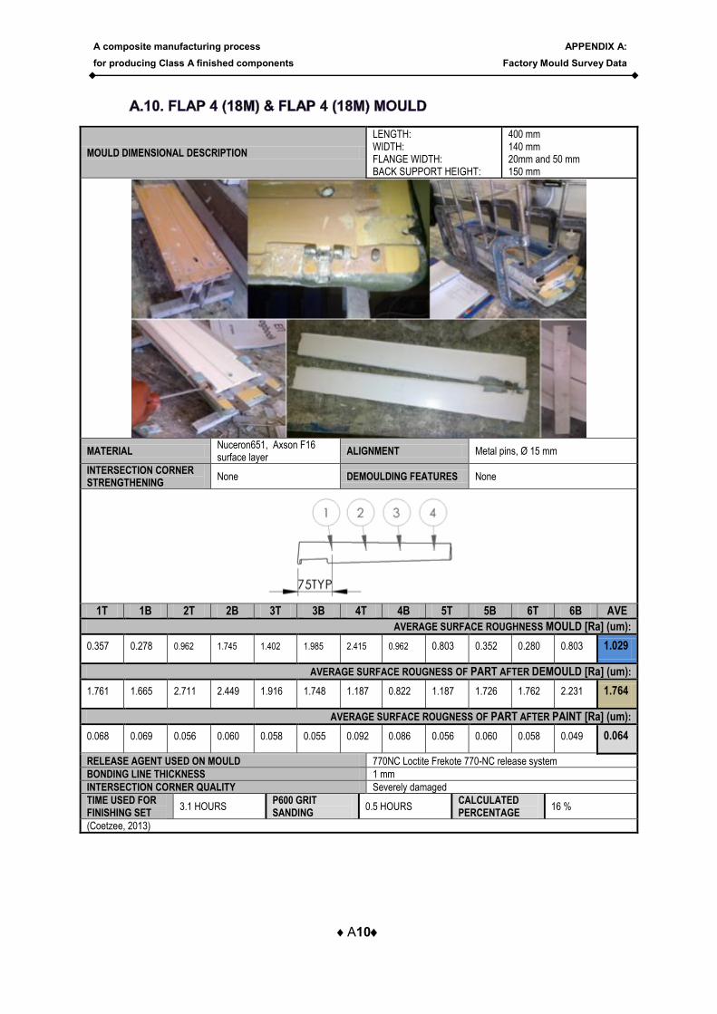
A10
MOULD DIMENSIONAL DESCRIPTION
LENGTH: WIDTH: FLANGE WIDTH: BACK SUPPORT HEIGHT:
400 mm 140 mm 20mm and 50 mm 150 mm
MATERIAL Nuceron651, Axson F16 surface layer
ALIGNMENT Metal pins, Ø 15 mm
INTERSECTION CORNER STRENGTHENING
None DEMOULDING FEATURES None
1T 1B 2T 2B 3T 3B 4T 4B 5T 5B 6T 6B AVE
AVERAGE SURFACE ROUGHNESS MOULD [Ra] (um):
0.357 0.278 0.962 1.745 1.402 1.985 2.415 0.962 0.803 0.352 0.280 0.803 1.029
AVERAGE SURFACE ROUGNESS OF PART AFTER DEMOULD [Ra] (um):
1.761 1.665 2.711 2.449 1.916 1.748 1.187 0.822 1.187 1.726 1.762 2.231 1.764
AVERAGE SURFACE ROUGNESS OF PART AFTER PAINT [Ra] (um):
0.068 0.069 0.056 0.060 0.058 0.055 0.092 0.086 0.056 0.060 0.058 0.049 0.064
RELEASE AGENT USED ON MOULD 770NC Loctite Frekote 770-NC release system
BONDING LINE THICKNESS 1 mm
INTERSECTION CORNER QUALITY Severely damaged
TIME USED FOR FINISHING SET
3.1 HOURS P600 GRIT SANDING
0.5 HOURS CALCULATED PERCENTAGE
16 %
(Coetzee, 2013)
A composite manufacturing process
for producing Class A finished components
APPENDIX A:
Factory Mould Survey Data
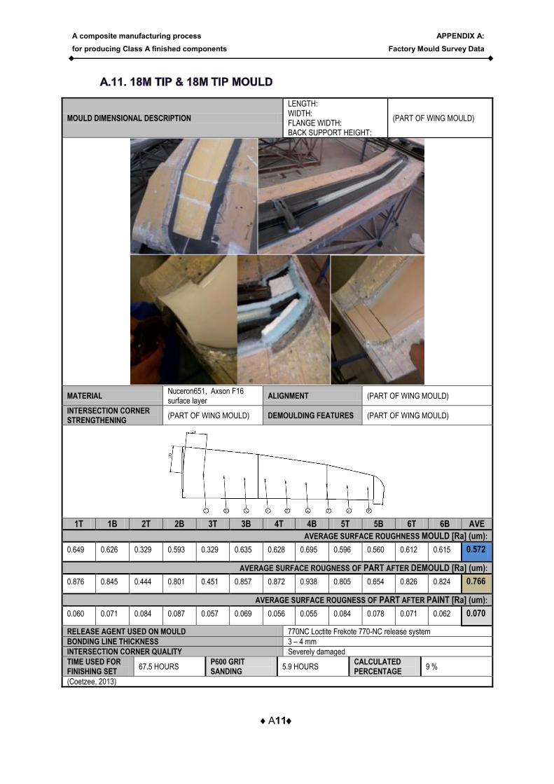
A11
MOULD DIMENSIONAL DESCRIPTION
LENGTH: WIDTH: FLANGE WIDTH: BACK SUPPORT HEIGHT:
(PART OF WING MOULD)
MATERIAL Nuceron651, Axson F16 surface layer
ALIGNMENT (PART OF WING MOULD)
INTERSECTION CORNER STRENGTHENING
(PART OF WING MOULD) DEMOULDING FEATURES (PART OF WING MOULD)
1T 1B 2T 2B 3T 3B 4T 4B 5T 5B 6T 6B AVE
AVERAGE SURFACE ROUGHNESS MOULD [Ra] (um):
0.649 0.626 0.329 0.593 0.329 0.635 0.628 0.695 0.596 0.560 0.612 0.615 0.572
AVERAGE SURFACE ROUGNESS OF PART AFTER DEMOULD [Ra] (um):
0.876 0.845 0.444 0.801 0.451 0.857 0.872 0.938 0.805 0.654 0.826 0.824 0.766
AVERAGE SURFACE ROUGNESS OF PART AFTER PAINT [Ra] (um):
0.060 0.071 0.084 0.087 0.057 0.069 0.056 0.055 0.084 0.078 0.071 0.062 0.070
RELEASE AGENT USED ON MOULD 770NC Loctite Frekote 770-NC release system
BONDING LINE THICKNESS 3 – 4 mm
INTERSECTION CORNER QUALITY Severely damaged
TIME USED FOR FINISHING SET
67.5 HOURS P600 GRIT SANDING
5.9 HOURS CALCULATED PERCENTAGE
9 %
(Coetzee, 2013)
A composite manufacturing process
for producing Class A finished components
APPENDIX A:
Factory Mould Survey Data
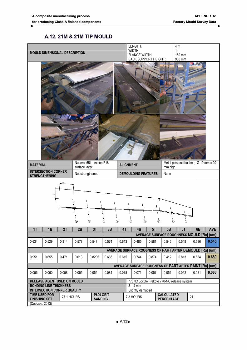
A12
MOULD DIMENSIONAL DESCRIPTION
LENGTH: WIDTH: FLANGE WIDTH: BACK SUPPORT HEIGHT:
4 m 1m 150 mm 900 mm
MATERIAL Nuceron651, Axson F16 surface layer
ALIGNMENT Metal pins and bushes; Ø 10 mm x 20 mm high.
INTERSECTION CORNER STRENGTHENING
Not strengthened DEMOULDING FEATURES None
1T 1B 2T 2B 3T 3B 4T 4B 5T 5B 6T 6B AVE
AVERAGE SURFACE ROUGHNESS MOULD [Ra] (um):
0.634 0.529 0.314 0.578 0.547 0.574 0.613 0.485 0.581 0.545 0.548 0.596 0.545
AVERAGE SURFACE ROUGNESS OF PART AFTER DEMOULD [Ra] (um):
0.951 0.655 0.471 0.613 0.8205 0.665 0.615 0.744 0.874 0.412 0.813 0.634 0.689
AVERAGE SURFACE ROUGNESS OF PART AFTER PAINT [Ra] (um):
0.056 0.060 0.058 0.055 0.055 0.084 0.078 0.071 0.057 0.054 0.052 0.081 0.063
RELEASE AGENT USED ON MOULD 770NC Loctite Frekote 770-NC release system
BONDING LINE THICKNESS 3 – 4 mm
INTERSECTION CORNER QUALITY Slightly damaged
TIME USED FOR FINISHING SET
77.1 HOURS P600 GRIT SANDING
7.3 HOURS CALCULATED PERCENTAGE
21
(Coetzee, 2013)
A composite manufacturing process
for producing Class A finished components
APPENDIX A:
Factory Mould Survey Data
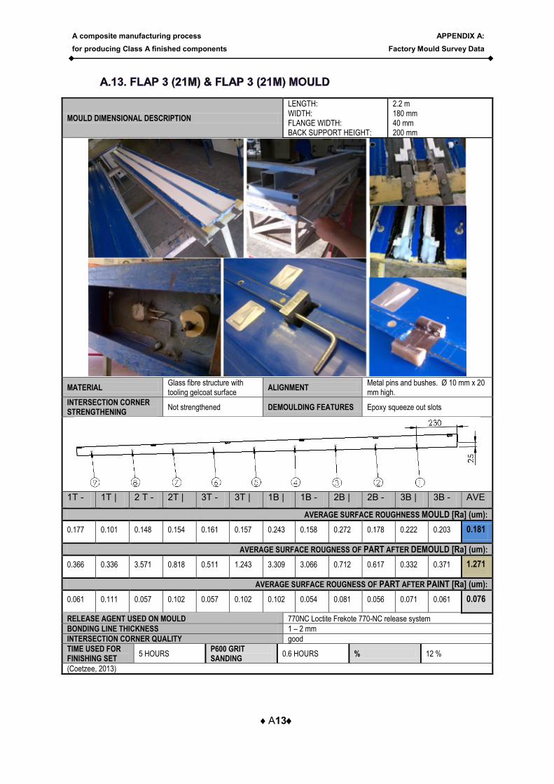
A13
MOULD DIMENSIONAL DESCRIPTION
LENGTH: WIDTH: FLANGE WIDTH: BACK SUPPORT HEIGHT:
2.2 m 180 mm 40 mm 200 mm
MATERIAL Glass fibre structure with tooling gelcoat surface
ALIGNMENT Metal pins and bushes. Ø 10 mm x 20 mm high.
INTERSECTION CORNER STRENGTHENING
Not strengthened DEMOULDING FEATURES Epoxy squeeze out slots
1T - 1T | 2 T - 2T | 3T - 3T | 1B | 1B - 2B | 2B - 3B | 3B - AVE
AVERAGE SURFACE ROUGHNESS MOULD [Ra] (um):
0.177 0.101 0.148 0.154 0.161 0.157 0.243 0.158 0.272 0.178 0.222 0.203 0.181
AVERAGE SURFACE ROUGNESS OF PART AFTER DEMOULD [Ra] (um):
0.366 0.336 3.571 0.818 0.511 1.243 3.309 3.066 0.712 0.617 0.332 0.371 1.271
AVERAGE SURFACE ROUGNESS OF PART AFTER PAINT [Ra] (um):
0.061 0.111 0.057 0.102 0.057 0.102 0.102 0.054 0.081 0.056 0.071 0.061 0.076
RELEASE AGENT USED ON MOULD 770NC Loctite Frekote 770-NC release system
BONDING LINE THICKNESS 1 – 2 mm
INTERSECTION CORNER QUALITY good
TIME USED FOR FINISHING SET
5 HOURS P600 GRIT SANDING
0.6 HOURS % 12 %
(Coetzee, 2013)
A composite manufacturing process
for producing Class A finished components
APPENDIX A:
Factory Mould Survey Data
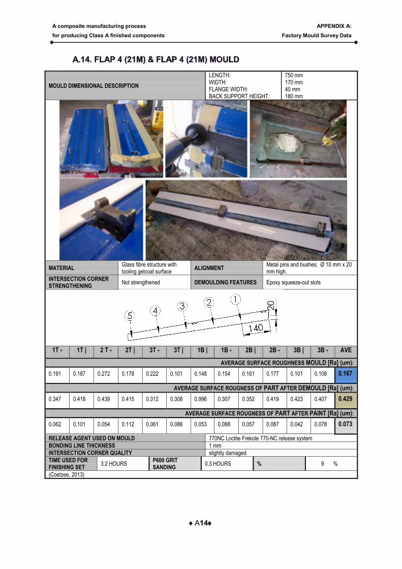
A14
MOULD DIMENSIONAL DESCRIPTION
LENGTH: WIDTH: FLANGE WIDTH: BACK SUPPORT HEIGHT:
750 mm 170 mm 40 mm 180 mm
MATERIAL Glass fibre structure with tooling gelcoat surface
ALIGNMENT Metal pins and bushes; Ø 10 mm x 20 mm high.
INTERSECTION CORNER STRENGTHENING
Not strengthened DEMOULDING FEATURES Epoxy squeeze-out slots
1T - 1T | 2 T - 2T | 3T - 3T | 1B | 1B - 2B | 2B - 3B | 3B - AVE
AVERAGE SURFACE ROUGHNESS MOULD [Ra] (um):
0.191 0.187 0.272 0.178 0.222 0.101 0.148 0.154 0.161 0.177 0.101 0.108 0.167
AVERAGE SURFACE ROUGNESS OF PART AFTER DEMOULD [Ra] (um):
0.347 0.418 0.439 0.415 0.312 0.308 0.996 0.307 0.352 0.419 0.423 0.407 0.429
AVERAGE SURFACE ROUGNESS OF PART AFTER PAINT [Ra] (um):
0.062 0.101 0.054 0.112 0.061 0.086 0.053 0.088 0.057 0.087 0.042 0.078 0.073
RELEASE AGENT USED ON MOULD 770NC Loctite Frekote 770-NC release system
BONDING LINE THICKNESS 1 mm
INTERSECTION CORNER QUALITY slightly damaged
TIME USED FOR FINISHING SET
3.2 HOURS P600 GRIT SANDING
0.3 HOURS % 9 %
(Coetzee, 2013)
A composite manufacturing process
for producing Class A finished components
APPENDIX B:
Extra detail on tests
B1
The purpose of the surface roughness testing is to provide a measurable value for each
sample and to determine whether one particular sample is in fact a better quality than the
other. Samples are compared in terms of their surface roughness (Rz) and the arithmetical
average height (Ra).
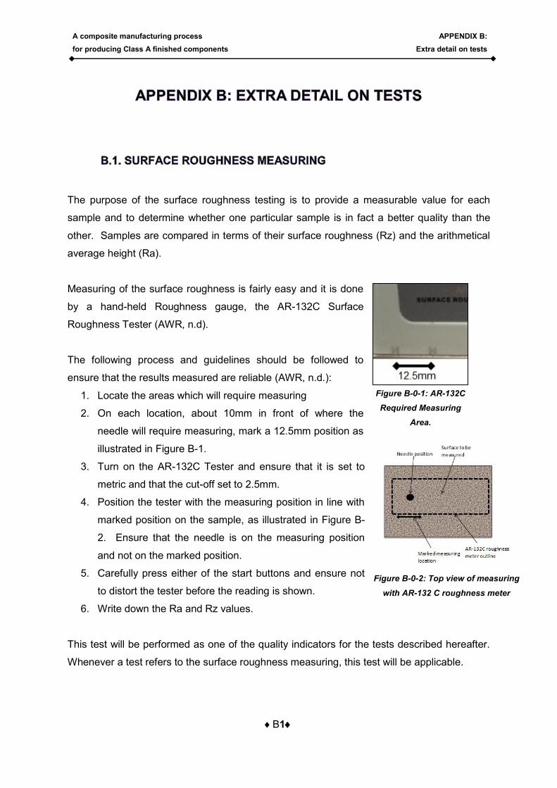
Measuring of the surface roughness is fairly easy and it is done
by a hand-held Roughness gauge, the AR-132C Surface
Roughness Tester (AWR, n.d).
The following process and guidelines should be followed to
ensure that the results measured are reliable (AWR, n.d.):
1. Locate the areas which will require measuring
2. On each location, about 10mm in front of where the
needle will require measuring, mark a 12.5mm position as
illustrated in Figure B-1.
3. Turn on the AR-132C Tester and ensure that it is set to
metric and that the cut-off set to 2.5mm.
4. Position the tester with the measuring position in line with
marked position on the sample, as illustrated in Figure B-
2. Ensure that the needle is on the measuring position
and not on the marked position.
5. Carefully press either of the start buttons and ensure not
to distort the tester before the reading is shown.
6. Write down the Ra and Rz values.
This test will be performed as one of the quality indicators for the tests described hereafter.
Whenever a test refers to the surface roughness measuring, this test will be applicable.
Figure B-0-1: AR-132C
Required Measuring
Area.
Figure B-0-2: Top view of measuring
with AR-132 C roughness meter
A composite manufacturing process
for producing Class A finished components
APPENDIX B:
Extra detail on tests
B2
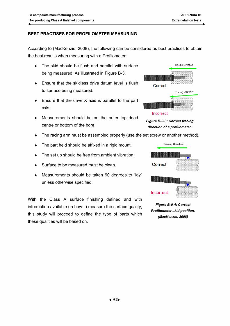
BEST PRACTISES FOR PROFILOMETER MEASURING
According to (MacKenzie, 2008), the following can be considered as best practises to obtain
the best results when measuring with a Profilometer:
The skid should be flush and parallel with surface
being measured. As illustrated in Figure B-3.
Ensure that the skidless drive datum level is flush
to surface being measured.
Ensure that the drive X axis is parallel to the part
axis.
Measurements should be on the outer top dead
centre or bottom of the bore.
The racing arm must be assembled properly (use the set screw or another method).
The part held should be affixed in a rigid mount.
The set up should be free from ambient vibration.
Surface to be measured must be clean.
Measurements should be taken 90 degrees to “lay”
unless otherwise specified.
With the Class A surface finishing defined and with
information available on how to measure the surface quality,
this study will proceed to define the type of parts which
these qualities will be based on.
Figure B-0-3: Correct tracing
direction of a profilometer.
Figure B-0-4: Correct
Profilometer skid position.
(MacKenzie, 2008)
A composite manufacturing process
for producing Class A finished components
APPENDIX B:
Extra detail on tests
B3
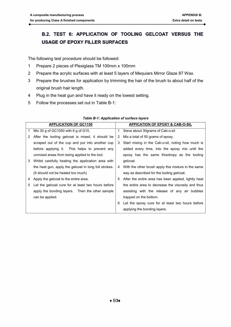
The following test procedure should be followed:
1 Prepare 2 pieces of Plexiglass TM 100mm x 100mm
2 Prepare the acrylic surfaces with at least 5 layers of Mequiars Mirror Glaze 87 Wax.
3 Prepare the brushes for application by trimming the hair of the brush to about half of the
original brush hair length.
4 Plug in the heat gun and have it ready on the lowest setting.
5 Follow the processes set out in Table B-1:
Table B-1: Application of surface layers
APPLICATION OF GC1150 APPICATION OF EPOXY & CAB-O-SIL
1 Mix 30 g of GC1050 with 6 g of G15.
2 After the tooling gelcoat is mixed, it should be
scraped out of the cup and put into another cup
before applying it. This helps to prevent any
unmixed areas from being applied to the tool.
3 Whilst carefully heating the application area with
the heat gun, apply the gelcoat in long full strokes.
(It should not be heated too much)
4 Apply the gelcoat to the entire area.
5 Let the gelcoat cure for at least two hours before
apply the bonding layers. Then the other sample
can be applied.
1 Sieve about 30grams of Cab-o-sil
2 Mix a total of 50 grams of epoxy.
3 Start mixing in the Cab-o-sil, noting how much is
added every time, into the epoxy mix until the
epoxy has the same thixotropy as the tooling
gelcoat.
4 With the other brush apply this mixture in the same
way as described for the tooling gelcoat.
5 After the entire area has been applied, lightly heat
the entire area to decrease the viscosity and thus
assisting with the release of any air bubbles
trapped on the bottom.
6 Let the epoxy cure for at least two hours before
applying the bonding layers.

A composite manufacturing process
for producing Class A finished components
APPENDIX B:
Extra detail on tests
B4
Application of layers
After the surface layers have cured for about 1h30min,
the following bonding/structural layers can be cut in
blocks (balanced & symmetric layup):
Table B-2: Orientation and layer style of samples
Layer number
Material Orientation layer style
1 Glass veil NA Layer A style
2 Glass veil NA Layer B style
3 90070 45 Layer A style
4 90070 90 Layer B style
5 92110 45 Layer A style
6 92110 90 Layer B style
7 92125 45 Layer A style
8 92125 90 Layer B style
9 92125 90 Layer A style
10 92125 45 Layer B style
11 92110 90 Layer A style
12 92110 45 Layer B style
13 90070 90 Layer A style
14 90070 45 Layer B style
Figure B-0-5: Layer style of Fibre
blocks
A composite manufacturing process
for producing Class A finished components
APPENDIX C:
Test 2 CNC Sample test data
C1
In this section the entire process of how the CNC samples were designed and manufactured
is explained. The section will first look at the design and will then explain the steps followed
for each of the individual features of the CNC test samples.
The CNC sample design needed to test certain features which influence CNC machining.
The “S”-shaped samples were designed to capture those features, whereas the block design
formed part of the conventional material tests.
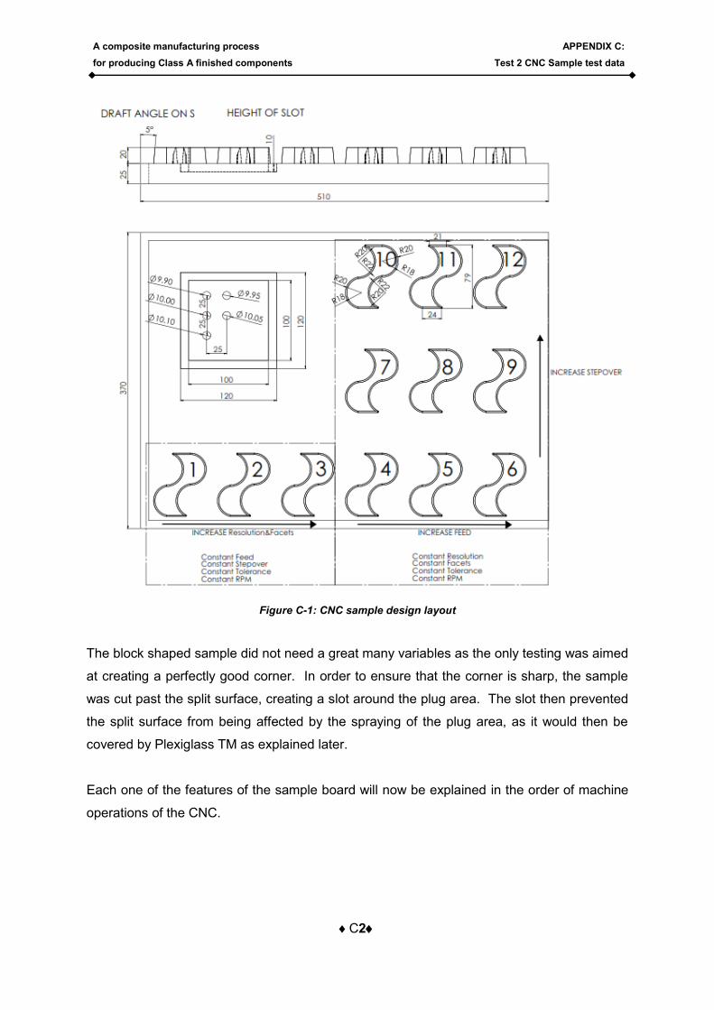
The “S”-shaped samples were all dimensionally the same and had the following features, as
illustrated in the Figure C-1:
- As only one size ball nose cutter would be used, the radiuses needed to be larger
than the radius of the cutter. The cutter size was 12mm, thus the radii were made
22mm.
- The samples needed to have a draft angle as to let the cutter avoid roughening a 90
degree vertical surface when it is cutting close to the bottom
- The samples needed to form curves, as flat block samples (like the block in the
sample board) only need the roughing tools to obtain a perfectly good surface finish,
whereas curves need the use of ball nose cutters.
- The sample needed to change direction, as any change in direction of the sample
can cause defect points in the cutting process, which will reflect on resulted sample.
- Because the surface roughness actually needed testing, the top surface needed to
be flat, to allow for a more accurate testing surface.
A composite manufacturing process
for producing Class A finished components
APPENDIX C:
Test 2 CNC Sample test data
C2
Figure C-1: CNC sample design layout
The block shaped sample did not need a great many variables as the only testing was aimed
at creating a perfectly good corner. In order to ensure that the corner is sharp, the sample
was cut past the split surface, creating a slot around the plug area. The slot then prevented
the split surface from being affected by the spraying of the plug area, as it would then be
covered by Plexiglass TM as explained later.
Each one of the features of the sample board will now be explained in the order of machine
operations of the CNC.

A composite manufacturing process
for producing Class A finished components
APPENDIX C:
Test 2 CNC Sample test data
C3
CNC machining consists of a few steps that are necessary in order to optimise tool
capabilities. The part is first broadly roughened to a near shape, and then roughened more
to a close near shape with a roughening tool. After the roughening is completed, the actually
testing starts by applying different settings to a ball nose cutter.
The final steps are each completed on its own. This section will explain these steps in order
of the machining processes, with illustrations taken from the VISICAM software used to
program the SCM RECORD 110 AL PRISMA, CNC machine, which makes use of the Xilog
Plus operating software for cutting. Each one of the different tools has been programmed
into the Visicadcam software. The Tables below provide information for each individual step
in the process:

A composite manufacturing process
for producing Class A finished components
APPENDIX C:
Test 2 CNC Sample test data
C4
Tool used: T3 - END MILL Ø40mm ROUGHNING SPIRAL IN
Cutting illustration SETTINGS
Pa
ss
es
Side allowance 0.5
Bottom allowance 0.5
Step-over method Spiral in
Step-over setting 20
Step down method Automatic
Step down setting 4
Lim
it
Min 20
Max 50
Boundary Past L
ea
ds
Plunging method Helical
Rapid style Clearance plane
Lead in Horizontal
Lead out Horizontal
Cu
ttin
g
pa
ram
ete
rs Cut mode Rough
Spindle speed ( rev/min) 17109
Feed (mm/min) 7186
Reduction feed (mm/min) 3596
RESOLUTION 20
FACETS 2.5
tim
e
Time taken to cut
21min
A composite manufacturing process
for producing Class A finished components
APPENDIX C:
Test 2 CNC Sample test data
C5
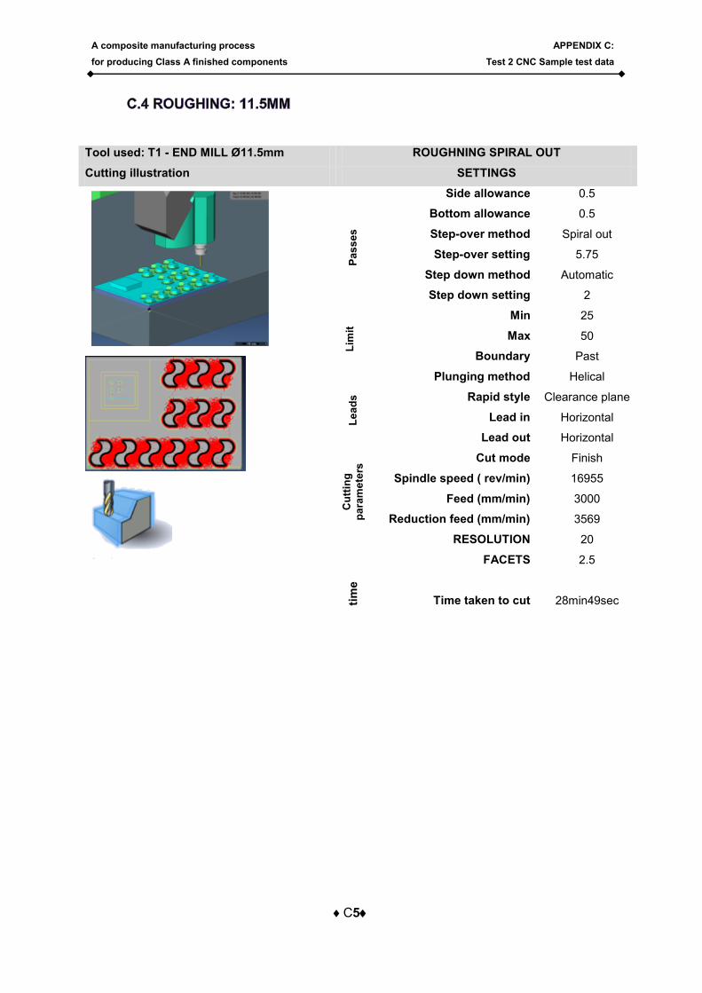
Tool used: T1 - END MILL Ø11.5mm ROUGHNING SPIRAL OUT
Cutting illustration SETTINGS
Pa
ss
es
Side allowance 0.5
Bottom allowance 0.5
Step-over method Spiral out
Step-over setting 5.75
Step down method Automatic
Step down setting 2
Lim
it
Min 25
Max 50
Boundary Past L
ea
ds
Plunging method Helical
Rapid style Clearance plane
Lead in Horizontal
Lead out Horizontal
Cu
ttin
g
pa
ram
ete
rs Cut mode Finish
Spindle speed ( rev/min) 16955
Feed (mm/min) 3000
Reduction feed (mm/min) 3569
RESOLUTION 20
FACETS 2.5
tim
e
Time taken to cut
28min49sec
A composite manufacturing process
for producing Class A finished components
APPENDIX C:
Test 2 CNC Sample test data
C6
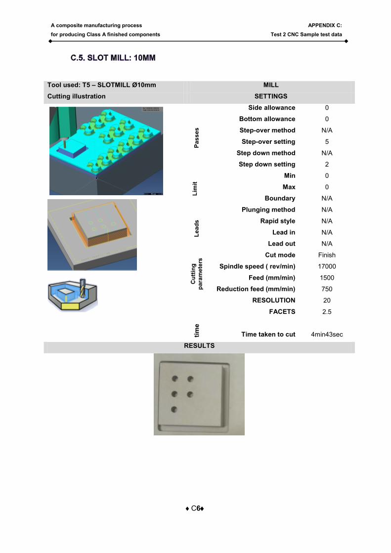
Tool used: T5 – SLOTMILL Ø10mm MILL
Cutting illustration SETTINGS
Pa
ss
es
Side allowance 0
Bottom allowance 0
Step-over method N/A
Step-over setting 5
Step down method N/A
Step down setting 2
Lim
it
Min 0
Max 0
Boundary N/A L
ea
ds
Plunging method N/A
Rapid style N/A
Lead in N/A
Lead out N/A
Cu
ttin
g
pa
ram
ete
rs Cut mode Finish
Spindle speed ( rev/min) 17000
Feed (mm/min) 1500
Reduction feed (mm/min) 750
RESOLUTION 20
FACETS 2.5
tim
e
Time taken to cut
4min43sec
RESULTS

A composite manufacturing process
for producing Class A finished components
APPENDIX C:
Test 2 CNC Sample test data
C7
Tool used: T9 – SLOTMILL Ø6.05mm MILL
Cutting illustration SETTINGS
Pa
ss
es
Side allowance 0
Bottom allowance 0
Step-over method N/A
Step-over setting 3.025
Step down method N?A
Step down setting 2
Lim
it
Min 0
Max 0
Boundary N/A
Le
ad
s
Plunging method N/A
Rapid style N/A
Lead in N/A
Lead out N/A
Cu
ttin
g
pa
ram
ete
rs Cut mode Finish
Spindle speed ( rev/min) 17000
Feed (mm/min) 1000
Reduction feed (mm/min) 1000
RESOLUTION
FACETS
tim
e
Time taken to cut
1min9sec
HOLE DIAMETERS RESULTS
HOLE PROGRAMMED
DIAMETER
FITMENT WITH G6
TOLERANCE SHAFTS
For a 10mm g6 shaft, the best setting for the
CNC machine is 9.95 and 10 mm
1 9.9 TO SMALL
2 9.95 FIT
3 10 FIT
4 10.05 TO LOOSE
5 10.1 TO LOOSE
1 2
3 4
5
A composite manufacturing process
for producing Class A finished components
APPENDIX C:
Test 2 CNC Sample test data
C8
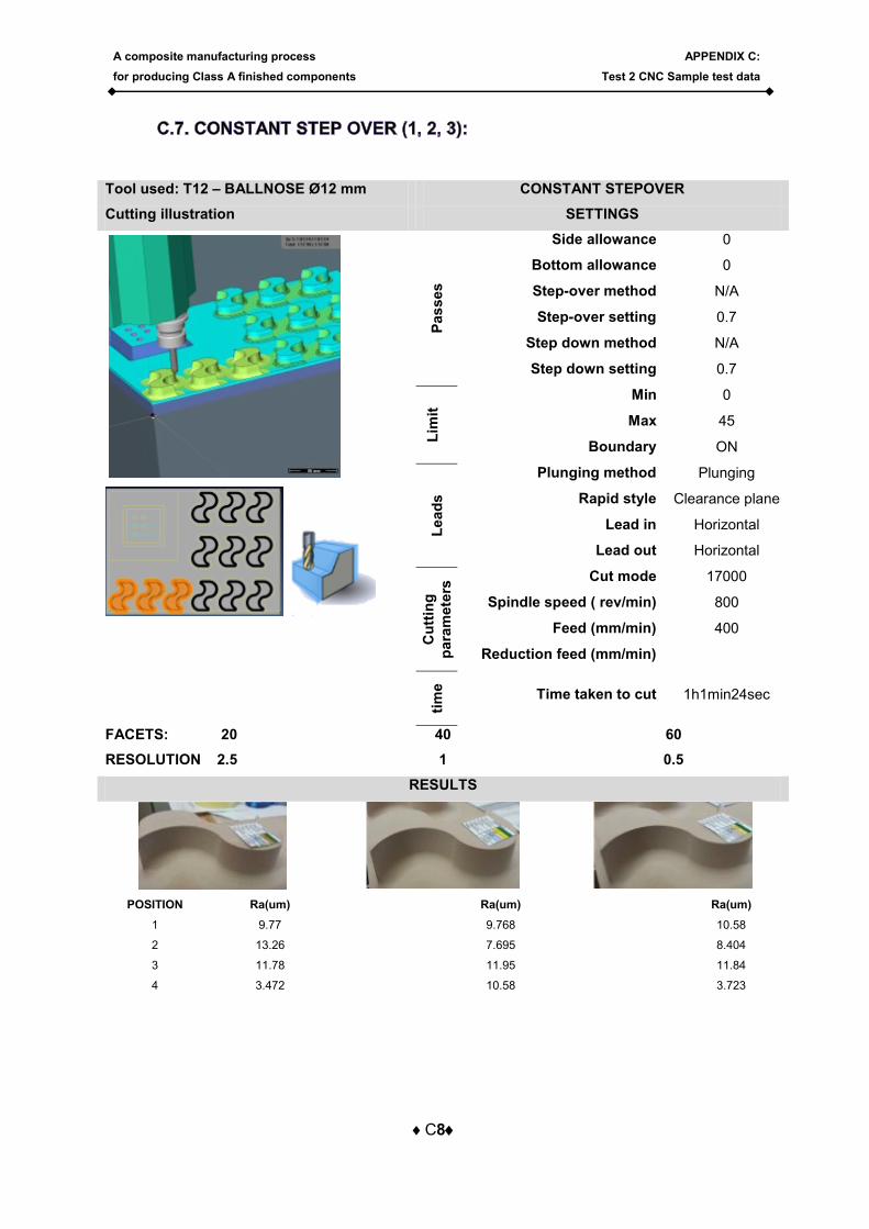
Tool used: T12 – BALLNOSE Ø12 mm CONSTANT STEPOVER
Cutting illustration SETTINGS
Pas
ses
Side allowance 0
Bottom allowance 0
Step-over method N/A
Step-over setting 0.7
Step down method N/A
Step down setting 0.7
Lim
it
Min 0
Max 45
Boundary ON L
ead
s
Plunging method Plunging
Rapid style Clearance plane
Lead in Horizontal
Lead out Horizontal
Cu
ttin
g
para
mete
rs Cut mode 17000
Spindle speed ( rev/min) 800
Feed (mm/min) 400
Reduction feed (mm/min)
tim
e
Time taken to cut 1h1min24sec
FACETS: 20 40 60
RESOLUTION 2.5 1 0.5
RESULTS
POSITION Ra(um) Ra(um) Ra(um)
1 9.77 9.768 10.58
2 13.26 7.695 8.404
3 11.78 11.95 11.84
4 3.472 10.58 3.723
A composite manufacturing process
for producing Class A finished components
APPENDIX C:
Test 2 CNC Sample test data
C9
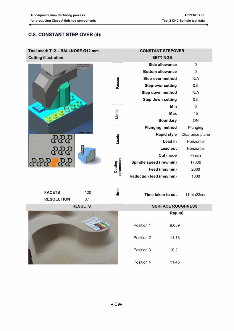
Tool used: T12 – BALLNOSE Ø12 mm CONSTANT STEPOVER
Cutting illustration SETTINGS
FACETS 120
RESOLUTION 0.1
Pa
ss
es
Side allowance 0
Bottom allowance 0
Step-over method N/A
Step-over setting 0.5
Step down method N/A
Step down setting 0.5
Lim
it
Min 0
Max 45
Boundary ON L
ea
ds
Plunging method Plunging
Rapid style Clearance plane
Lead in Horizontal
Lead out Horizontal
Cu
ttin
g
pa
ram
ete
rs Cut mode Finish
Spindle speed ( rev/min) 17000
Feed (mm/min) 2000
Reduction feed (mm/min) 1000
tim
e
Time taken to cut
11min23sec
RESULTS SURFACE ROUGHNESS
Ra(um)
Position 1 9.659
Position 2 11.18
Position 3 10.2
Position 4 11.45
A composite manufacturing process
for producing Class A finished components
APPENDIX C:
Test 2 CNC Sample test data
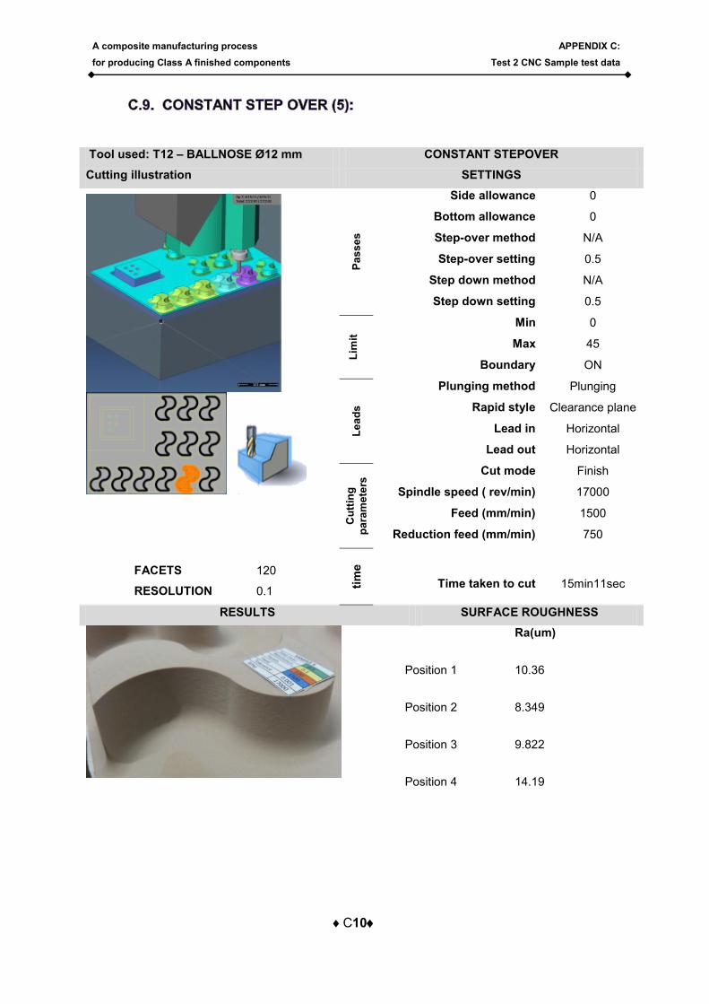
C10
Tool used: T12 – BALLNOSE Ø12 mm CONSTANT STEPOVER
Cutting illustration SETTINGS
FACETS 120
RESOLUTION 0.1
Pa
ss
es
Side allowance 0
Bottom allowance 0
Step-over method N/A
Step-over setting 0.5
Step down method N/A
Step down setting 0.5
Lim
it
Min 0
Max 45
Boundary ON L
ea
ds
Plunging method Plunging
Rapid style Clearance plane
Lead in Horizontal
Lead out Horizontal
Cu
ttin
g
pa
ram
ete
rs Cut mode Finish
Spindle speed ( rev/min) 17000
Feed (mm/min) 1500
Reduction feed (mm/min) 750
tim
e
Time taken to cut
15min11sec
RESULTS SURFACE ROUGHNESS
Ra(um)
Position 1 10.36
Position 2 8.349
Position 3 9.822
Position 4 14.19
A composite manufacturing process
for producing Class A finished components
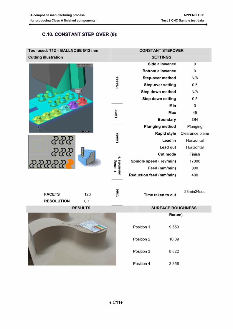
APPENDIX C:
Test 2 CNC Sample test data
C11
Tool used: T12 – BALLNOSE Ø12 mm CONSTANT STEPOVER
Cutting illustration SETTINGS
FACETS 120
RESOLUTION 0.1
Pa
ss
es
Side allowance 0
Bottom allowance 0
Step-over method N/A
Step-over setting 0.5
Step down method N/A
Step down setting 0.5
Lim
it
Min 0
Max 45
Boundary ON L
ea
ds
Plunging method Plunging
Rapid style Clearance plane
Lead in Horizontal
Lead out Horizontal
Cu
ttin
g
pa
ram
ete
rs Cut mode Finish
Spindle speed ( rev/min) 17000
Feed (mm/min) 800
Reduction feed (mm/min) 400
tim
e
Time taken to cut 28min24sec
RESULTS SURFACE ROUGHNESS
Ra(um)
Position 1 9.659
Position 2 10.09
Position 3 8.622
Position 4 3.356
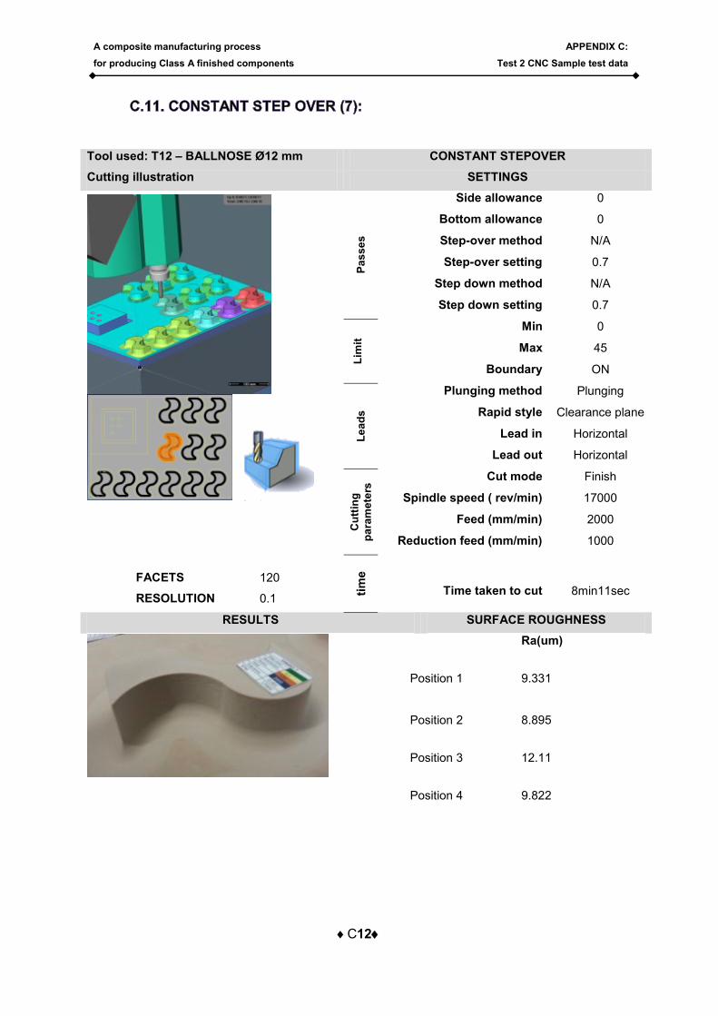
A composite manufacturing process
for producing Class A finished components
APPENDIX C:
Test 2 CNC Sample test data
C12
Tool used: T12 – BALLNOSE Ø12 mm CONSTANT STEPOVER
Cutting illustration SETTINGS
FACETS 120
RESOLUTION 0.1
Pa
ss
es
Side allowance 0
Bottom allowance 0
Step-over method N/A
Step-over setting 0.7
Step down method N/A
Step down setting 0.7
Lim
it
Min 0
Max 45
Boundary ON L
ea
ds
Plunging method Plunging
Rapid style Clearance plane
Lead in Horizontal
Lead out Horizontal
Cu
ttin
g
pa
ram
ete
rs Cut mode Finish
Spindle speed ( rev/min) 17000
Feed (mm/min) 2000
Reduction feed (mm/min) 1000
tim
e
Time taken to cut
8min11sec
RESULTS SURFACE ROUGHNESS
Ra(um)
Position 1 9.331
Position 2 8.895
Position 3 12.11
Position 4 9.822
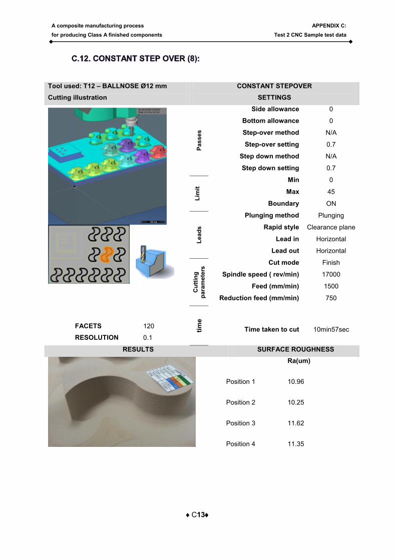
A composite manufacturing process
for producing Class A finished components
APPENDIX C:
Test 2 CNC Sample test data
C13
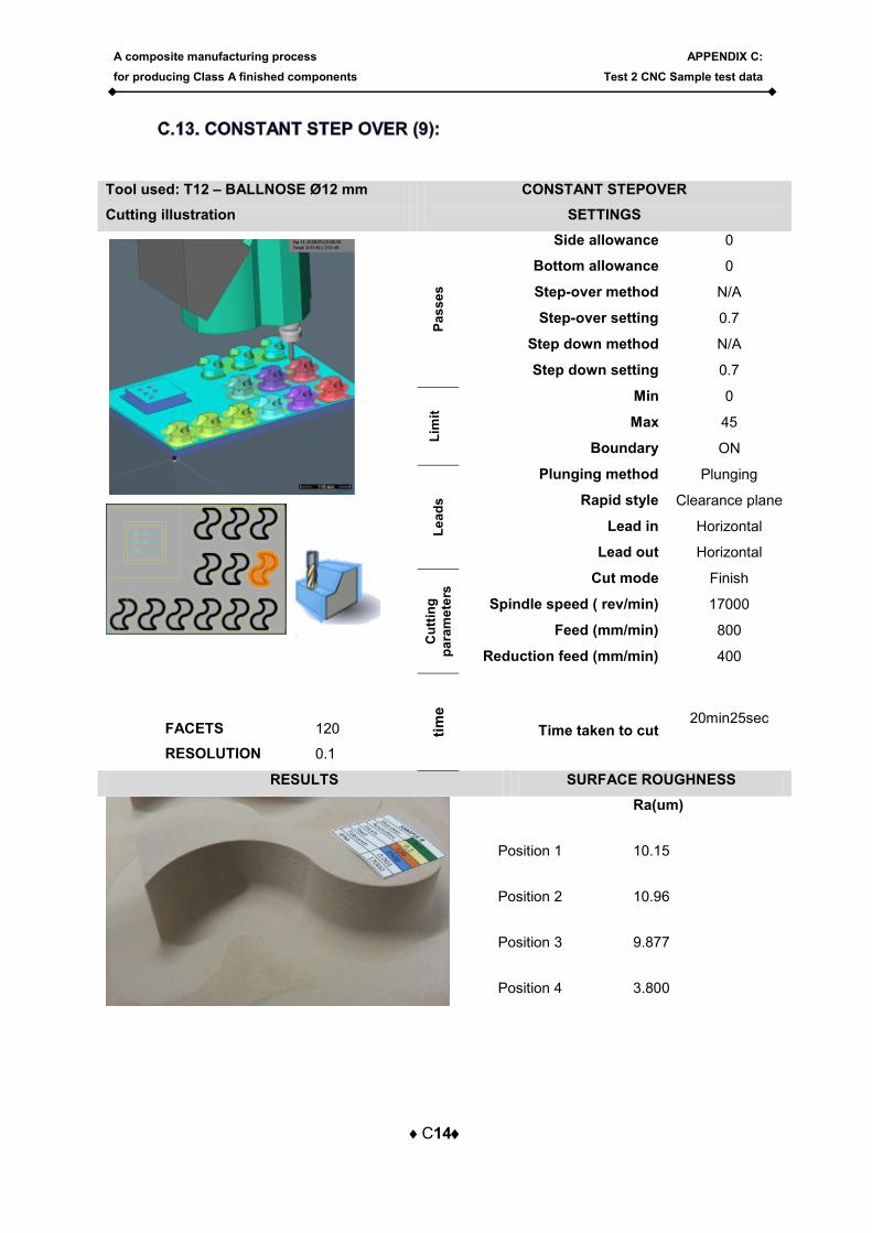
Tool used: T12 – BALLNOSE Ø12 mm CONSTANT STEPOVER
Cutting illustration SETTINGS
FACETS 120
RESOLUTION 0.1
Pa
ss
es
Side allowance 0
Bottom allowance 0
Step-over method N/A
Step-over setting 0.7
Step down method N/A
Step down setting 0.7
Lim
it
Min 0
Max 45
Boundary ON L
ea
ds
Plunging method Plunging
Rapid style Clearance plane
Lead in Horizontal
Lead out Horizontal
Cu
ttin
g
pa
ram
ete
rs Cut mode Finish
Spindle speed ( rev/min) 17000
Feed (mm/min) 1500
Reduction feed (mm/min) 750
tim
e
Time taken to cut
10min57sec
RESULTS SURFACE ROUGHNESS
Ra(um)
Position 1 10.96
Position 2 10.25
Position 3 11.62
Position 4 11.35
A composite manufacturing process
for producing Class A finished components
APPENDIX C:
Test 2 CNC Sample test data
C14
Tool used: T12 – BALLNOSE Ø12 mm CONSTANT STEPOVER
Cutting illustration SETTINGS
FACETS 120
RESOLUTION 0.1
Pa
ss
es
Side allowance 0
Bottom allowance 0
Step-over method N/A
Step-over setting 0.7
Step down method N/A
Step down setting 0.7
Lim
it
Min 0
Max 45
Boundary ON L
ea
ds
Plunging method Plunging
Rapid style Clearance plane
Lead in Horizontal
Lead out Horizontal
Cu
ttin
g
pa
ram
ete
rs Cut mode Finish
Spindle speed ( rev/min) 17000
Feed (mm/min) 800
Reduction feed (mm/min) 400
tim
e
Time taken to cut 20min25sec
RESULTS SURFACE ROUGHNESS
Ra(um)
Position 1 10.15
Position 2 10.96
Position 3 9.877
Position 4 3.800
A composite manufacturing process
for producing Class A finished components
APPENDIX C:
Test 2 CNC Sample test data
C15
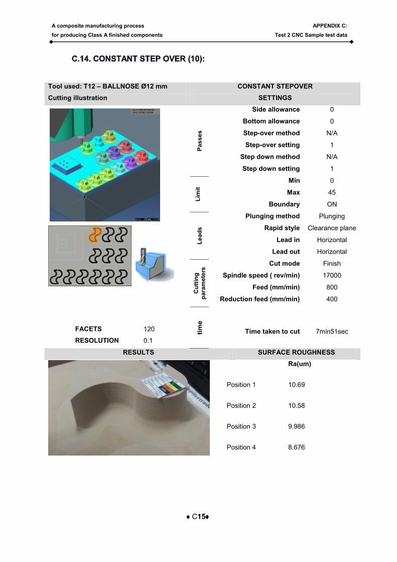
Tool used: T12 – BALLNOSE Ø12 mm CONSTANT STEPOVER
Cutting illustration SETTINGS
FACETS 120
RESOLUTION 0.1
Pa
ss
es
Side allowance 0
Bottom allowance 0
Step-over method N/A
Step-over setting 1
Step down method N/A
Step down setting 1
Lim
it
Min 0
Max 45
Boundary ON L
ea
ds
Plunging method Plunging
Rapid style Clearance plane
Lead in Horizontal
Lead out Horizontal
Cu
ttin
g
pa
ram
ete
rs Cut mode Finish
Spindle speed ( rev/min) 17000
Feed (mm/min) 800
Reduction feed (mm/min) 400
tim
e
Time taken to cut
7min51sec
RESULTS SURFACE ROUGHNESS
Ra(um)
Position 1 10.69
Position 2 10.58
Position 3 9.986
Position 4 8.676
A composite manufacturing process
for producing Class A finished components
APPENDIX C:
Test 2 CNC Sample test data
C16
Tool used: T12 – BALLNOSE Ø12 mm CONSTANT STEPOVER
Cutting illustration SETTINGS
FACETS 120
RESOLUTION 0.1
Pa
ss
es
Side allowance 0
Bottom allowance 0
Step-over method N/A
Step-over setting 1
Step down method N/A
Step down setting 1
Lim
it
Min 0
Max 45
Boundary ON L
ea
ds
Plunging method Plunging
Rapid style Clearance plane
Lead in Horizontal
Lead out Horizontal
Cu
ttin
g
pa
ram
ete
rs Cut mode Finish
Spindle speed ( rev/min) 17000
Feed (mm/min) 1500
Reduction feed (mm/min) 400
tim
e
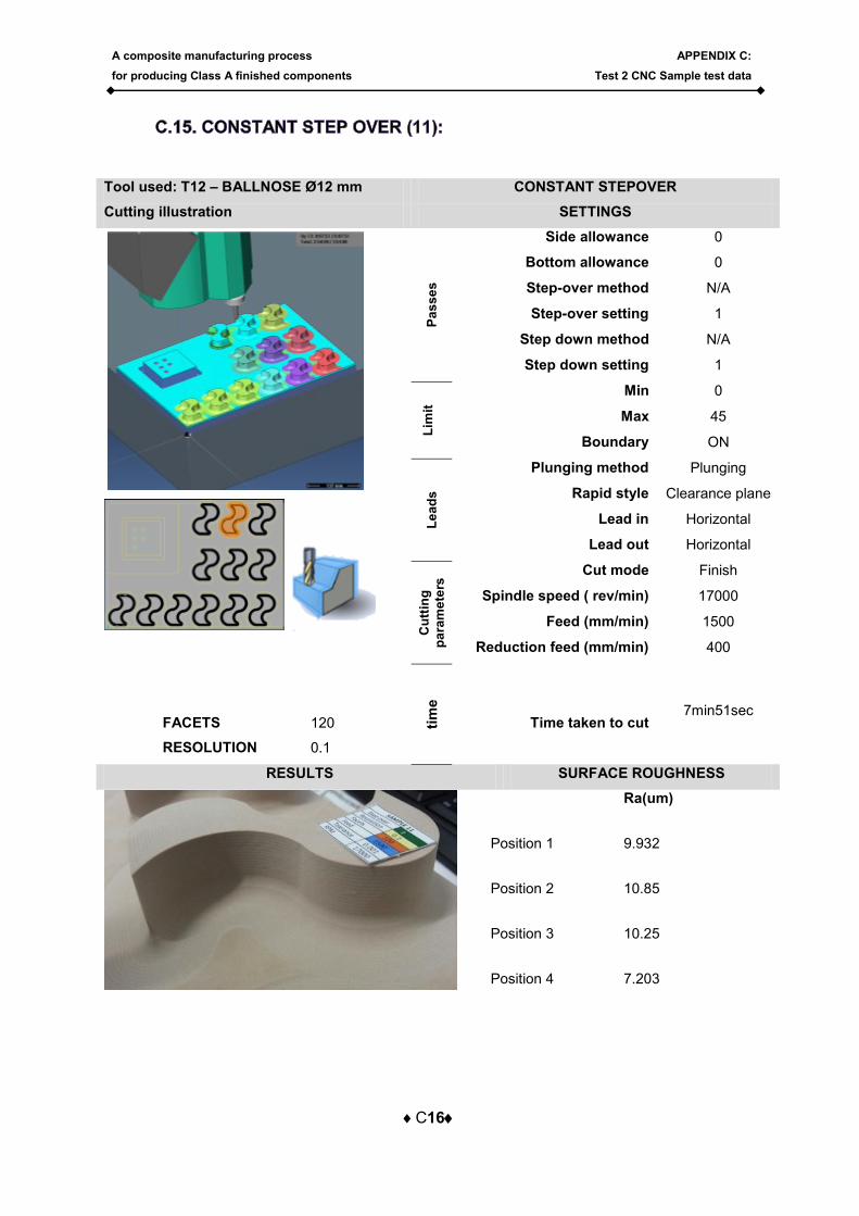
Time taken to cut 7min51sec
RESULTS SURFACE ROUGHNESS
Ra(um)
Position 1 9.932
Position 2 10.85
Position 3 10.25
Position 4 7.203
A composite manufacturing process
for producing Class A finished components
APPENDIX C:
Test 2 CNC Sample test data
C17
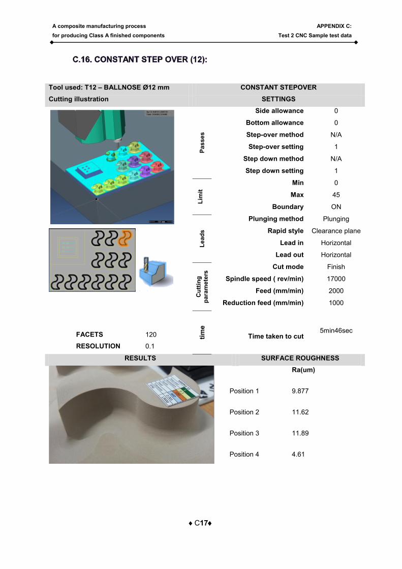
Tool used: T12 – BALLNOSE Ø12 mm CONSTANT STEPOVER
Cutting illustration SETTINGS
FACETS 120
RESOLUTION 0.1
Pa
ss
es
Side allowance 0
Bottom allowance 0
Step-over method N/A
Step-over setting 1
Step down method N/A
Step down setting 1
Lim
it
Min 0
Max 45
Boundary ON L
ea
ds
Plunging method Plunging
Rapid style Clearance plane
Lead in Horizontal
Lead out Horizontal
Cu
ttin
g
pa
ram
ete
rs Cut mode Finish
Spindle speed ( rev/min) 17000
Feed (mm/min) 2000
Reduction feed (mm/min) 1000
tim
e
Time taken to cut 5min46sec
RESULTS SURFACE ROUGHNESS
Ra(um)
Position 1 9.877
Position 2 11.62
Position 3 11.89
Position 4 4.61
A composite manufacturing process
for producing Class A finished components
APPENDIX C:
Test 2 CNC Sample test data
C18
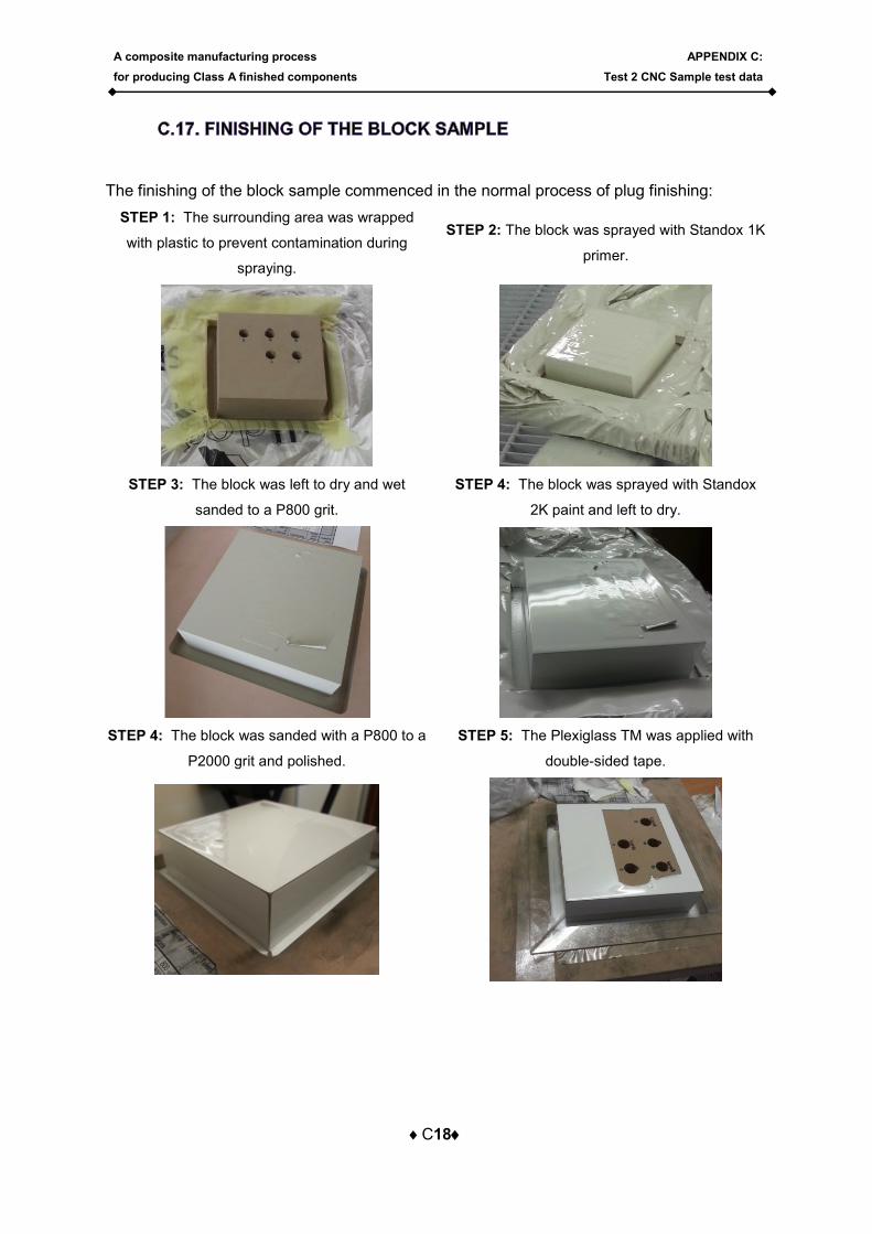
The finishing of the block sample commenced in the normal process of plug finishing:
STEP 1: The surrounding area was wrapped
with plastic to prevent contamination during
spraying.
STEP 2: The block was sprayed with Standox 1K
primer.
STEP 3: The block was left to dry and wet
sanded to a P800 grit.
STEP 4: The block was sprayed with Standox
2K paint and left to dry.
STEP 4: The block was sanded with a P800 to a
P2000 grit and polished.
STEP 5: The Plexiglass TM was applied with
double-sided tape.
A composite manufacturing process
for producing Class A finished components
APPENDIX D:
Manufacturing of instrument panel
D1
The manufacturing of the instrument panel that has been used to verify the process
described in Chapter 6 is described in this Appendix. The process started with the CAD
design and the plug manufacturing, it then proceeds to the mould design and manufacturing
and ends with the part manufacturing
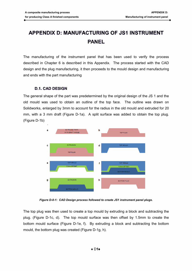
The general shape of the part was predetermined by the original design of the JS 1 and the
old mould was used to obtain an outline of the top face. The outline was drawn on
Solidworks, enlarged by 3mm to account for the radius in the old mould and extruded for 20
mm, with a 3 mm draft (Figure D-1a). A split surface was added to obtain the top plug.
(Figure D-1b)
Figure D-0-1: CAD Design process followed to create JS1 instrument panel plugs.
The top plug was then used to create a top mould by extruding a block and subtracting the
plug. (Figure D-1c, d). The top mould surface was then offset by 1.5mm to create the
bottom mould surface (Figure D-1e, f). By extruding a block and subtracting the bottom
mould, the bottom plug was created (Figure D-1g, h).
A composite manufacturing process
for producing Class A finished components
APPENDIX D:
Manufacturing of instrument panel
D2
The plugs were created by importing the parasolid file, created by the CAD modelling, into
VISCAM and creating the tool paths with settings set out in Chapter 6. The plugs were then
cut on the CNC machine out of Nuceron651 tooling board. After cutting, the plugs were
finished.
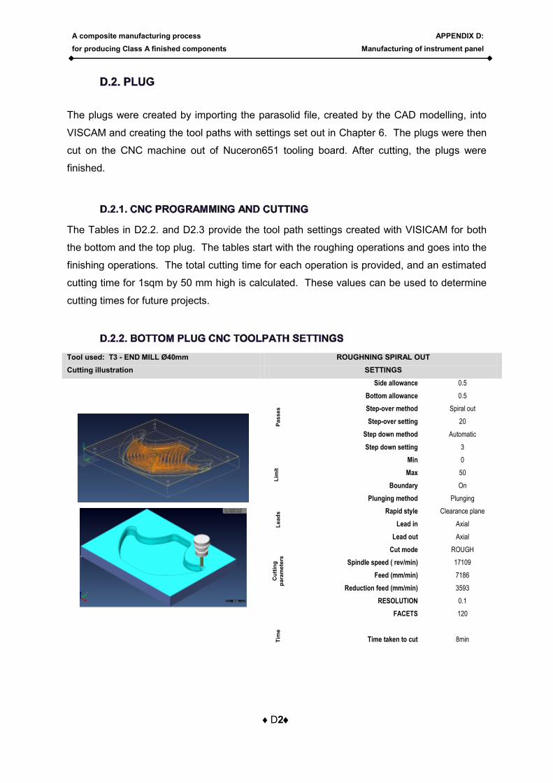
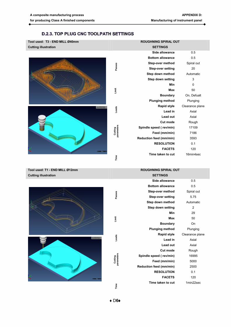
The Tables in D2.2. and D2.3 provide the tool path settings created with VISICAM for both
the bottom and the top plug. The tables start with the roughing operations and goes into the
finishing operations. The total cutting time for each operation is provided, and an estimated
cutting time for 1sqm by 50 mm high is calculated. These values can be used to determine
cutting times for future projects.
Tool used: T3 - END MILL Ø40mm ROUGHNING SPIRAL OUT
Cutting illustration SETTINGS
Pa
ss
es
Side allowance 0.5
Bottom allowance 0.5
Step-over method Spiral out
Step-over setting 20
Step down method Automatic
Step down setting 3
Lim
it
Min 0
Max 50
Boundary On
Le
ad
s
Plunging method Plunging
Rapid style Clearance plane
Lead in Axial
Lead out Axial
Cu
ttin
g
pa
ram
ete
rs
Cut mode ROUGH
Spindle speed ( rev/min) 17109
Feed (mm/min) 7186
Reduction feed (mm/min) 3593
RESOLUTION 0.1
FACETS 120
Tim
e
Time taken to cut
8min
A composite manufacturing process
for producing Class A finished components
APPENDIX D:
Manufacturing of instrument panel
D3
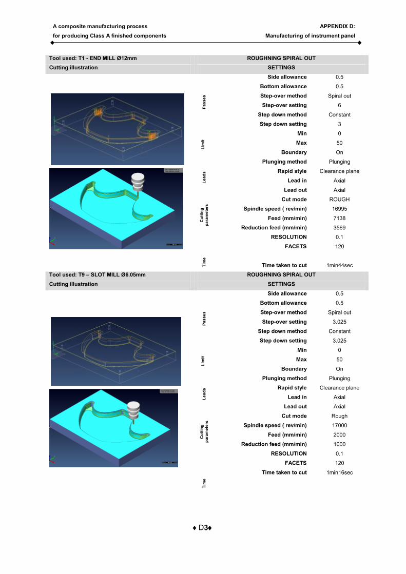
Tool used: T1 - END MILL Ø12mm ROUGHNING SPIRAL OUT
Cutting illustration SETTINGS
Pa
ss
es
Side allowance 0.5
Bottom allowance 0.5
Step-over method Spiral out
Step-over setting 6
Step down method Constant
Step down setting 3
Lim
it
Min 0
Max 50
Boundary On
Le
ad
s
Plunging method Plunging
Rapid style Clearance plane
Lead in Axial
Lead out Axial
Cu
ttin
g
pa
ram
ete
rs
Cut mode ROUGH
Spindle speed ( rev/min) 16995
Feed (mm/min) 7138
Reduction feed (mm/min) 3569
RESOLUTION 0.1
FACETS 120
Tim
e
Time taken to cut
1min44sec
Tool used: T9 – SLOT MILL Ø6.05mm ROUGHNING SPIRAL OUT
Cutting illustration SETTINGS
Pa
ss
es
Side allowance 0.5
Bottom allowance 0.5
Step-over method Spiral out
Step-over setting 3.025
Step down method Constant
Step down setting 3.025
Lim
it
Min 0
Max 50
Boundary On
Le
ad
s
Plunging method Plunging
Rapid style Clearance plane
Lead in Axial
Lead out Axial
Cu
ttin
g
pa
ram
ete
rs
Cut mode Rough
Spindle speed ( rev/min) 17000
Feed (mm/min) 2000
Reduction feed (mm/min) 1000
RESOLUTION 0.1
FACETS 120
Tim
e
Time taken to cut 1min16sec
A composite manufacturing process
for producing Class A finished components
APPENDIX D:
Manufacturing of instrument panel
D4
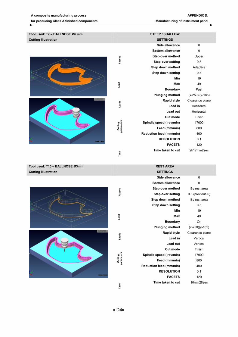
Tool used: T7 – BALLNOSE Ø6 mm STEEP / SHALLOW
Cutting illustration SETTINGS
Pa
ss
es
Side allowance 0
Bottom allowance 0
Step-over method Upper
Step-over setting 0.5
Step down method Adaptive
Step down setting 0.5
Lim
it
Min 19
Max 49
Boundary Past
Le
ad
s
Plunging method (x-250) (y-185)
Rapid style Clearance plane
Lead in Horizontal
Lead out Horizontal
Cu
ttin
g
pa
ram
ete
rs
Cut mode Finish
Spindle speed ( rev/min) 17000
Feed (mm/min) 800
Reduction feed (mm/min) 400
RESOLUTION 0.1
FACETS 120
Tim
e Time taken to cut 2h17min2sec
Tool used: T10 – BALLNOSE Ø3mm REST AREA
Cutting illustration SETTINGS
Pa
ss
es
Side allowance 0
Bottom allowance 0
Step-over method By rest area
Step-over setting 0.5 (previous 6)
Step down method By rest area
Step down setting 0.5
Lim
it
Min 19
Max 49
Boundary On
Le
ad
s
Plunging method (x-250)(y-185)
Rapid style Clearance plane
Lead in Vertical
Lead out Vertical
Cu
ttin
g
pa
ram
ete
rs
Cut mode Finish
Spindle speed ( rev/min) 17000
Feed (mm/min) 800
Reduction feed (mm/min) 400
RESOLUTION 0.1
FACETS 120
Tim
e Time taken to cut 10min28sec
A composite manufacturing process
for producing Class A finished components
APPENDIX D:
Manufacturing of instrument panel
D5
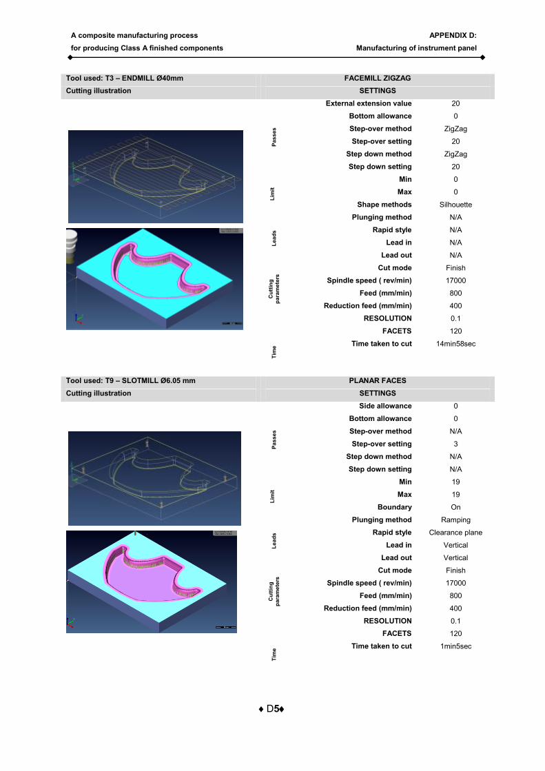
Tool used: T3 – ENDMILL Ø40mm FACEMILL ZIGZAG
Cutting illustration SETTINGS
Pa
ss
es
External extension value 20
Bottom allowance 0
Step-over method ZigZag
Step-over setting 20
Step down method ZigZag
Step down setting 20
Lim
it
Min 0
Max 0
Shape methods Silhouette
Le
ad
s
Plunging method N/A
Rapid style N/A
Lead in N/A
Lead out N/A
Cu
ttin
g
pa
ram
ete
rs
Cut mode Finish
Spindle speed ( rev/min) 17000
Feed (mm/min) 800
Reduction feed (mm/min) 400
RESOLUTION 0.1
FACETS 120
Tim
e Time taken to cut 14min58sec
Tool used: T9 – SLOTMILL Ø6.05 mm PLANAR FACES
Cutting illustration SETTINGS
Pa
ss
es
Side allowance 0
Bottom allowance 0
Step-over method N/A
Step-over setting 3
Step down method N/A
Step down setting N/A
Lim
it
Min 19
Max 19
Boundary On
Le
ad
s
Plunging method Ramping
Rapid style Clearance plane
Lead in Vertical
Lead out Vertical
Cu
ttin
g
pa
ram
ete
rs
Cut mode Finish
Spindle speed ( rev/min) 17000
Feed (mm/min) 800
Reduction feed (mm/min) 400
RESOLUTION 0.1
FACETS 120
Tim
e Time taken to cut 1min5sec
A composite manufacturing process
for producing Class A finished components
APPENDIX D:
Manufacturing of instrument panel
D6
Tool used: T3 - END MILL Ø40mm ROUGHNING SPIRAL OUT
Cutting illustration SETTINGS
Pa
ss
es
Side allowance 0.5
Bottom allowance 0.5
Step-over method Spiral out
Step-over setting 20
Step down method Automatic
Step down setting 3
Lim
it
Min 0
Max 50
Boundary On, Defualt
Le
ad
s
Plunging method Plunging
Rapid style Clearance plane
Lead in Axial
Lead out Axial C
utt
ing
pa
ram
ete
rs
Cut mode Rough
Spindle speed ( rev/min) 17109
Feed (mm/min) 7186
Reduction feed (mm/min) 3593
RESOLUTION 0.1
FACETS 120
Tim
e Time taken to cut 16min4sec
Tool used: T1 - END MILL Ø12mm ROUGHNING SPIRAL OUT
Cutting illustration SETTINGS
Pa
ss
es
Side allowance 0.5
Bottom allowance 0.5
Step-over method Spiral out
Step-over setting 5.75
Step down method Automatic
Step down setting 2
Lim
it
Min 29
Max 50
Boundary On
Le
ad
s
Plunging method Plunging
Rapid style Clearance plane
Lead in Axial
Lead out Axial
Cu
ttin
g
pa
ram
ete
rs
Cut mode Rough
Spindle speed ( rev/min) 16995
Feed (mm/min) 5000
Reduction feed (mm/min) 2500
RESOLUTION 0.1
FACETS 120
Tim
e Time taken to cut 1min22sec
A composite manufacturing process
for producing Class A finished components
APPENDIX D:
Manufacturing of instrument panel
D7
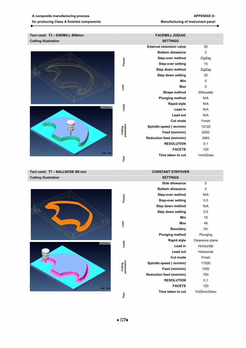
Tool used: T3 – ENDMILL Ø40mm FACEMILL ZIGZAG
Cutting illustration SETTINGS
Pa
ss
es
External extension value 50
Bottom allowance 0
Step-over method ZigZag
Step-over setting 15
Step down method ZigZag
Step down setting 20
Lim
it
Min 0
Max 0
Shape method Silhouette
Le
ad
s
Plunging method N/A
Rapid style N/A
Lead in N/A
Lead out N/A
Cu
ttin
g
pa
ram
ete
rs
Cut mode Finish
Spindle speed ( rev/min) 15120
Feed (mm/min) 6350
Reduction feed (mm/min) 3593
RESOLUTION 0.1
FACETS 120
Tim
e Time taken to cut 1min52sec
Tool used: T7 – BALLNOSE Ø6 mm CONSTANT STEPOVER
Cutting illustration SETTINGS
Pa
ss
es
Side allowance 0
Bottom allowance 0
Step-over method N/A
Step-over setting 0.5
Step down method N/A
Step down setting 0.5
Lim
it
Min 19
Max 49
Boundary On
Le
ad
s
Plunging method Plunging
Rapid style Clearance plane
Lead in Horizontal
Lead out Horizontal
Cu
ttin
g
pa
ram
ete
rs
Cut mode Finish
Spindle speed ( rev/min) 17000
Feed (mm/min) 1500
Reduction feed (mm/min) 750
RESOLUTION 0.1
FACETS 120
Tim
e Time taken to cut 1h22min33sec
A composite manufacturing process
for producing Class A finished components
APPENDIX D:
Manufacturing of instrument panel
D8
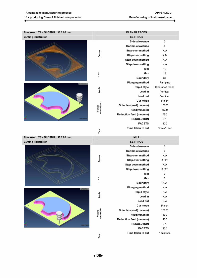
Tool used: T9 – SLOTMILL Ø 6.05 mm PLANAR FACES
Cutting illustration SETTINGS
Pa
ss
es
Side allowance 0
Bottom allowance 0
Step-over method N/A
Step-over setting 2.8
Step down method N/A
Step down setting N/A
Lim
it
Min 19
Max 19
Boundary On
Le
ad
s
Plunging method Ramping
Rapid style Clearance plane
Lead in Vertical
Lead out Vertical C
utt
ing
pa
ram
ete
rs
Cut mode Finish
Spindle speed( rev/min) 17000
Feed(mm/min) 1500
Reduction feed (mm/min) 750
RESOLUTION 0.1
FACETS 120
Tim
e Time taken to cut 37min11sec
Tool used: T9 – SLOTMILL Ø 6.05 mm MILL
Cutting illustration SETTINGS
Pa
ss
es
Side allowance 0
Bottom allowance 0
Step-over method N/A
Step-over setting 3.025
Step down method N/A
Step down setting 3.025
Lim
it
Min 0
Max 0
Boundary N/A
Le
ad
s
Plunging method N/A
Rapid style N/A
Lead in N/A
Lead out N/A
Cu
ttin
g
pa
ram
ete
rs
Cut mode Finish
Spindle speed( rev/min) 17000
Feed(mm/min) 800
Reduction feed (mm/min) 400
RESOLUTION 0.1
FACETS 120
Tim
e Time taken to cut 1min5sec
A composite manufacturing process
for producing Class A finished components
APPENDIX D:
Manufacturing of instrument panel
D9
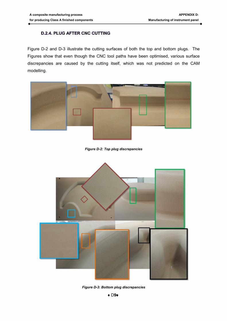
Figure D-2 and D-3 illustrate the cutting surfaces of both the top and bottom plugs. The
Figures show that even though the CNC tool paths have been optimised, various surface
discrepancies are caused by the cutting itself, which was not predicted on the CAM
modelling.
Figure D-2: Top plug discrepancies
Figure D-3: Bottom plug discrepancies
A composite manufacturing process
for producing Class A finished components
APPENDIX D:
Manufacturing of instrument panel
D10
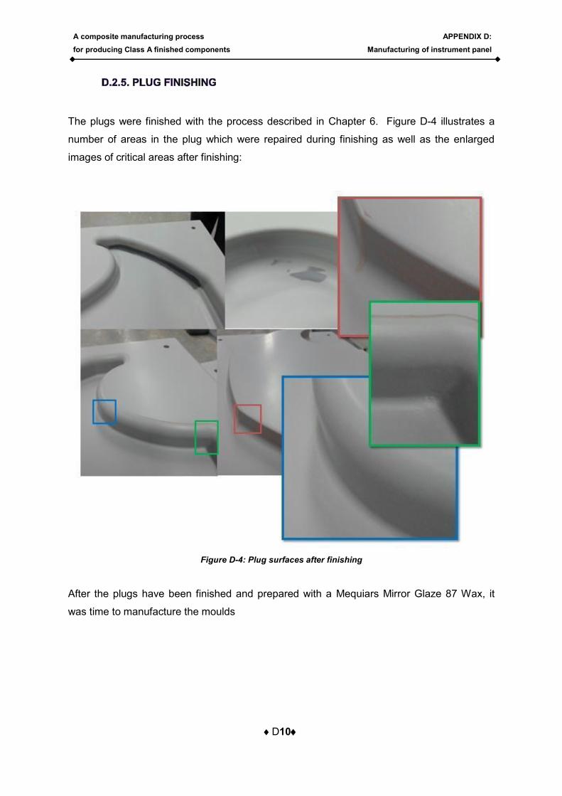
The plugs were finished with the process described in Chapter 6. Figure D-4 illustrates a
number of areas in the plug which were repaired during finishing as well as the enlarged
images of critical areas after finishing:
Figure D-4: Plug surfaces after finishing
After the plugs have been finished and prepared with a Mequiars Mirror Glaze 87 Wax, it
was time to manufacture the moulds

A composite manufacturing process
for producing Class A finished components
APPENDIX D:
Manufacturing of instrument panel
D11
Creating composite moulds requires one to follow a few steps involving both design and
manufacturing. The mould composition and mould inserts required designing after which the
inserts required manufacturing before the mould manufacturing commenced. This section
describes these processes in more detail, starting with the design of the mould layup. It
should be noted that the design part and insert manufacturing commenced parallel to the
plug manufacturing, as these processes were not influenced by each other. This ensured
that the moulds could be manufactured as soon as the plugs were finished. The first step in
the mould process was to design the mould layup.
Table D-1 indicates the balanced, symmetrical layup
schedule prepared for the manufacturing of composite
moulds. The materials used were all bidirectional, thus
eliminating the need for a counter angled layer of each
material. The brick layer styles are indicated in Figure D-
5.
To determine how much material was required, the total
area of the mould was calculated. The calculated areas
were used to determine how much material will be
required in the 45º and 90º direction. The quantities of
gelcoat and epoxy were also calculated, illustrated in
Table D-2.
Figure D-5: Brick layers styles
Table D-2: Area and material required calculations
Table D-1: Layup schedule of mould
A composite manufacturing process
for producing Class A finished components
APPENDIX D:
Manufacturing of instrument panel
D12
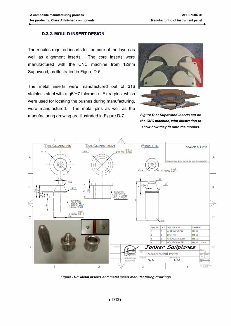
The moulds required inserts for the core of the layup as
well as alignment inserts. The core inserts were
manufactured with the CNC machine from 12mm
Supawood, as illustrated in Figure D-6.
The metal inserts were manufactured out of 316
stainless steel with a g6/H7 tolerance. Extra pins, which
were used for locating the bushes during manufacturing,
were manufactured. The metal pins as well as the
manufacturing drawing are illustrated in Figure D-7.
Figure D-7: Metal inserts and metal insert manufacturing drawings
Figure D-6: Supawood inserts cut on
the CNC machine, with illustration to
show how they fit onto the moulds.
A composite manufacturing process
for producing Class A finished components
APPENDIX D:
Manufacturing of instrument panel
D13
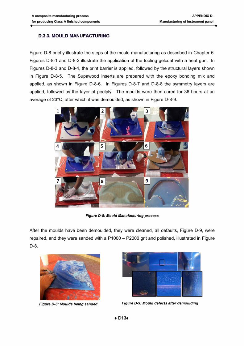
Figure D-8 briefly illustrate the steps of the mould manufacturing as described in Chapter 6.
Figures D-8-1 and D-8-2 illustrate the application of the tooling gelcoat with a heat gun. In
Figures D-8-3 and D-8-4, the print barrier is applied, followed by the structural layers shown
in Figure D-8-5. The Supawood inserts are prepared with the epoxy bonding mix and
applied, as shown in Figure D-8-6. In Figures D-8-7 and D-8-8 the symmetry layers are
applied, followed by the layer of peelply. The moulds were then cured for 36 hours at an
average of 23°C, after which it was demoulded, as shown in Figure D-8-9.
Figure D-8: Mould Manufacturing process
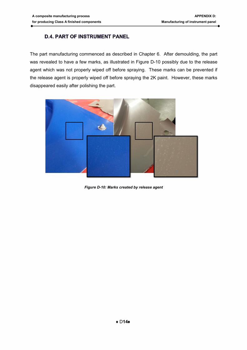
After the moulds have been demoulded, they were cleaned, all defaults, Figure D-9, were
repaired, and they were sanded with a P1000 – P2000 grit and polished, illustrated in Figure
D-8.
Figure D-9: Mould defects after demoulding Figure D-8: Moulds being sanded
A composite manufacturing process
for producing Class A finished components
APPENDIX D:
Manufacturing of instrument panel
D14
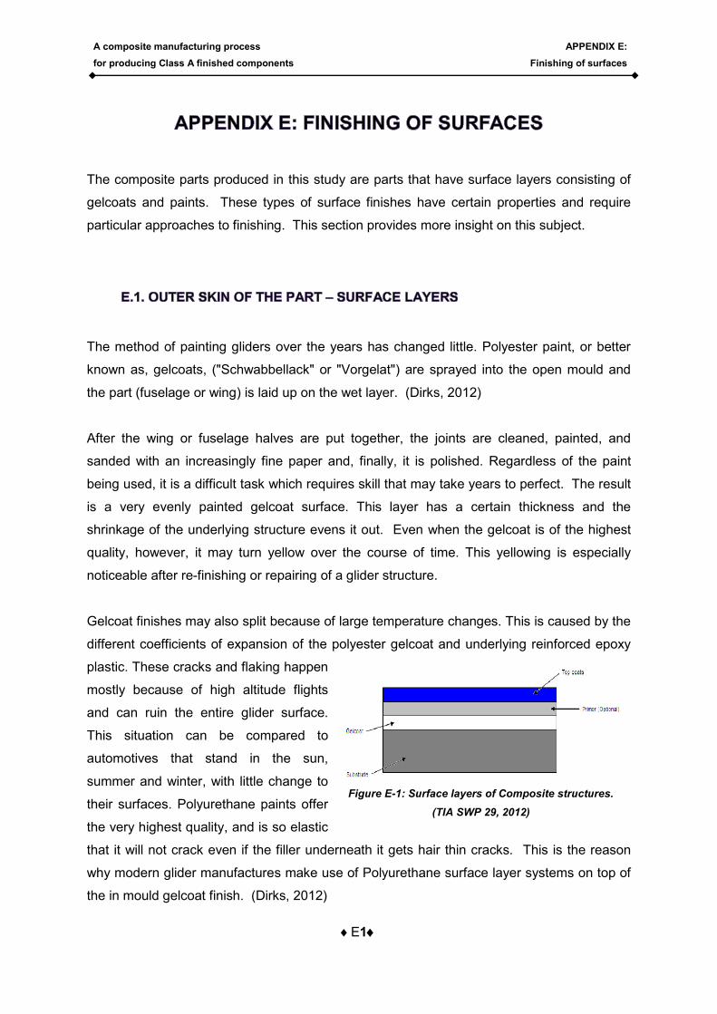
The part manufacturing commenced as described in Chapter 6. After demoulding, the part
was revealed to have a few marks, as illustrated in Figure D-10 possibly due to the release
agent which was not properly wiped off before spraying. These marks can be prevented if
the release agent is properly wiped off before spraying the 2K paint. However, these marks
disappeared easily after polishing the part.
Figure D-10: Marks created by release agent
A composite manufacturing process
for producing Class A finished components
APPENDIX E:
Finishing of surfaces
E1
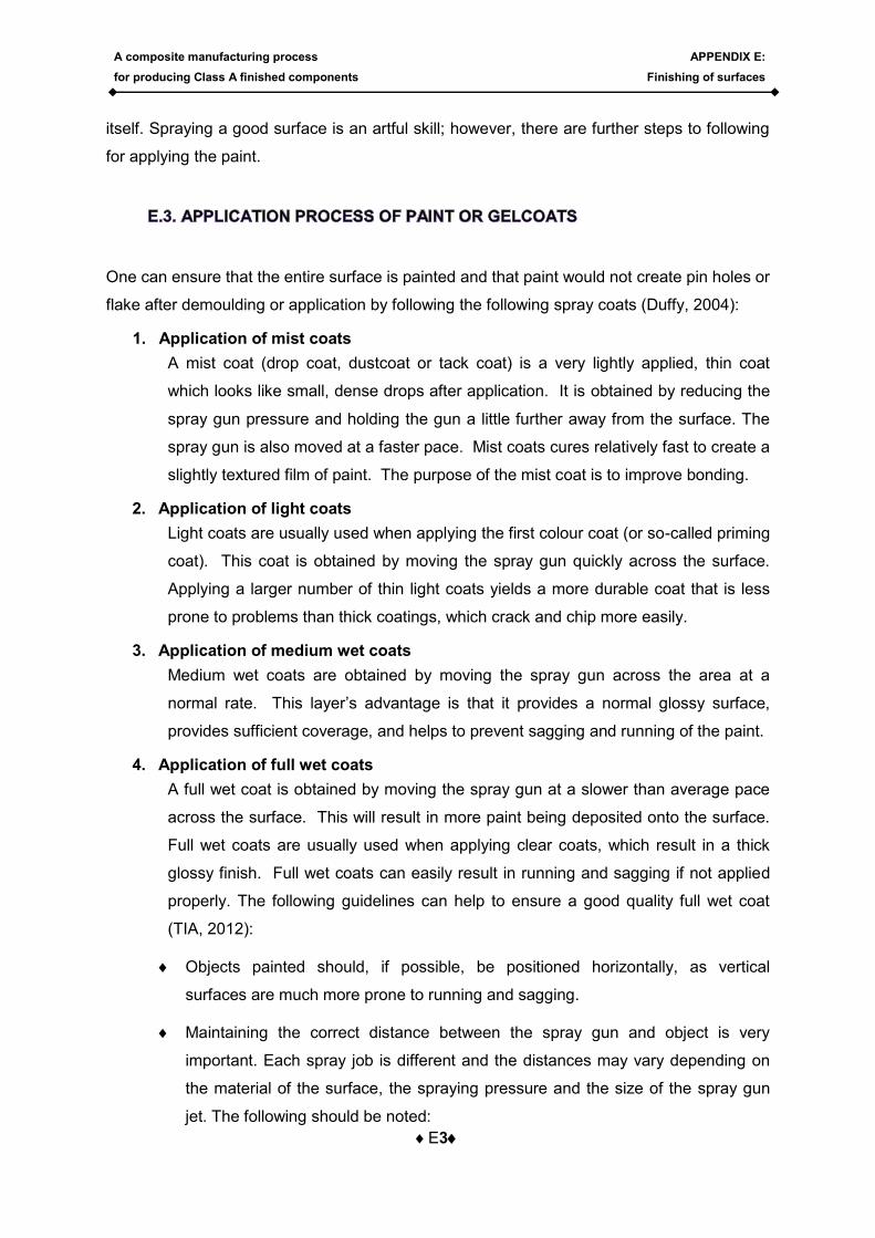
Figure E-1: Surface layers of Composite structures.
(TIA SWP 29, 2012)
The composite parts produced in this study are parts that have surface layers consisting of
gelcoats and paints. These types of surface finishes have certain properties and require
particular approaches to finishing. This section provides more insight on this subject.
The method of painting gliders over the years has changed little. Polyester paint, or better
known as, gelcoats, ("Schwabbellack" or "Vorgelat") are sprayed into the open mould and
the part (fuselage or wing) is laid up on the wet layer. (Dirks, 2012)
After the wing or fuselage halves are put together, the joints are cleaned, painted, and
sanded with an increasingly fine paper and, finally, it is polished. Regardless of the paint
being used, it is a difficult task which requires skill that may take years to perfect. The result
is a very evenly painted gelcoat surface. This layer has a certain thickness and the
shrinkage of the underlying structure evens it out. Even when the gelcoat is of the highest
quality, however, it may turn yellow over the course of time. This yellowing is especially
noticeable after re-finishing or repairing of a glider structure.
Gelcoat finishes may also split because of large temperature changes. This is caused by the
different coefficients of expansion of the polyester gelcoat and underlying reinforced epoxy
plastic. These cracks and flaking happen
mostly because of high altitude flights
and can ruin the entire glider surface.
This situation can be compared to
automotives that stand in the sun,
summer and winter, with little change to
their surfaces. Polyurethane paints offer
the very highest quality, and is so elastic
that it will not crack even if the filler underneath it gets hair thin cracks. This is the reason
why modern glider manufactures make use of Polyurethane surface layer systems on top of
the in mould gelcoat finish. (Dirks, 2012)

A composite manufacturing process
for producing Class A finished components
APPENDIX E:
Finishing of surfaces
E2
Finishing the glider with Polyurethane in the mould is, however, not conventional at the
moment, and the current study will investigate possibilities of applying Polyurethane paints
as topcoats with in-mould coatings to produce Class A finished composite structures directly
out of the mould. Because the mould finishing for these types of parts plays a significant
role in the part’s finishing, an entire section will now be devoted to the manufacturing of
moulds for these types of parts. (Dirks, 2012)
Several preparations are required for the spray painter to achieve an evenly applied gloss
shiny surface, which is free from dust flaws, pinholes, orange peel, and so on (TIA, 2012).
These include:
The surface to be sprayed on must be flawless, clean of dust or any other
contamination.
The paint must be selected and mixed correctly.
To obtain the correct viscosity of the paint, the correct amount of thinners must
be applied.
The spraying plays a crucial part and the spray area should be kept clean and
properly maintained.
It is essential to spray in a dust free environment like a spray booth.
The spray environment and surface to be coated must be kept at the prescribed
standards of the paint system to be used.
The spray gun jet must be selected correctly and be adjusted according to the
surface to be sprayed on.
Always let the paint layers flash before applying the next layer, as this will result
in better bonding between layers.
Any disturbance of the painter whilst spraying may result in thicker application or
may cause the formation to run. It is thus crucial that the area around the paint
job is obstacle free and that the spray gun airline must have sufficient reach.
Following these guidelines entails good practice and will help to ensure that the greatest
number of paint flaws is prevented, but it still does not ensure a good quality surface by
A composite manufacturing process
for producing Class A finished components
APPENDIX E:
Finishing of surfaces
E3
itself. Spraying a good surface is an artful skill; however, there are further steps to following
for applying the paint.
One can ensure that the entire surface is painted and that paint would not create pin holes or
flake after demoulding or application by following the following spray coats (Duffy, 2004):
1. Application of mist coats
A mist coat (drop coat, dustcoat or tack coat) is a very lightly applied, thin coat
which looks like small, dense drops after application. It is obtained by reducing the
spray gun pressure and holding the gun a little further away from the surface. The
spray gun is also moved at a faster pace. Mist coats cures relatively fast to create a
slightly textured film of paint. The purpose of the mist coat is to improve bonding.
2. Application of light coats
Light coats are usually used when applying the first colour coat (or so-called priming
coat). This coat is obtained by moving the spray gun quickly across the surface.
Applying a larger number of thin light coats yields a more durable coat that is less
prone to problems than thick coatings, which crack and chip more easily.
3. Application of medium wet coats
Medium wet coats are obtained by moving the spray gun across the area at a
normal rate. This layer’s advantage is that it provides a normal glossy surface,
provides sufficient coverage, and helps to prevent sagging and running of the paint.
4. Application of full wet coats
A full wet coat is obtained by moving the spray gun at a slower than average pace
across the surface. This will result in more paint being deposited onto the surface.
Full wet coats are usually used when applying clear coats, which result in a thick
glossy finish. Full wet coats can easily result in running and sagging if not applied
properly. The following guidelines can help to ensure a good quality full wet coat
(TIA, 2012):
Objects painted should, if possible, be positioned horizontally, as vertical
surfaces are much more prone to running and sagging.
Maintaining the correct distance between the spray gun and object is very
important. Each spray job is different and the distances may vary depending on
the material of the surface, the spraying pressure and the size of the spray gun
jet. The following should be noted:
A composite manufacturing process
for producing Class A finished components
APPENDIX E:
Finishing of surfaces
E4
Holding the spray gun to close to the object results in the spray angle to
decrease. This results in over-depositing of paint to the surface and usually
results in running of the paint.
Holding the spray gun too far from the object causes the material to almost
dry before it reaches the surface. The painted surface will be rough which
results in orange peel and a loss of glossiness.
The spray gun should be held exactly parallel to the object and not arched. While
spraying, the gun needs to be moved in smooth and slow wave-like movements,
so that the colour jet of the next spray route overlaps the preceding half of the
sprayed route.
By spraying crosswise, an equally coloured surface is obtained. This is achieved
by leading the gun from left to right (a horizontal process). This is followed by
transposing the jet head and leading the gun from top to bottom (vertical
process). The spray stripes should overlap wet in wet. This spraying process is
right-angled and therefore this method of gun leading is known as the “cross
process”. The process further requires that the edges of an object must be
sprayed before the areas that are more difficult to reach.
Care should be taken when filling and closing the cover of the cup of the gun, as
any paint drops which fall onto the object will cause running.
If these steps are followed by a trained painter, the resulted paint layers of the surface will be
of good quality; however, there are still a large number of causes that can result in poor paint
jobs.
A composite manufacturing process
for producing Class A finished components
APPENDIX E:
Finishing of surfaces
E5
The polishing of a painted surface can involve various abrasive pastes and liquids, which
can be applied by either hand or machine. Machine compounds reduce the polishing time,
but intricate corners and dwells or smaller parts are difficult to polish. In these cases hand
compounding may be used to obtain the sufficient surface quality.
Because sanding to a P2000 quality already produces a high surface quality, one might feel
that polishing is not required. The following reasons for polishing are provided (Canning,
1982):
To achieve a bright, semi-bright and textured surface finish for decorative and
aesthetic purposes.
To create a suitable basis for further coating.
To remove surface imperfections and contaminants.
To improve and refine the surface.
One must always use the appropriate machine compound and only apply correct sufficient
amount to polish a small area. The compound should be worked around the face of the pad
and over the surface before the machine is switched on. This will prevent the compound
from flying from the surface when the machine is switched on.
Compounds have the tendency to dry out and thus buffing of large areas should be avoided.
Even when small areas are buffed, the machine should be moved around the surface
constantly. If it is kept at one place, it may burn through the topcoat.
A higher machine speed will result in a deeper shine. The following procedures should be
followed along with the guidelines above:
The machine should be kept at a 5 degree angle to the surface and only tilted to
reach into corners or match curve lines.
The machine should not be pushed down into the surface, as it can cut through the
topcoat. Rather let the machine do the work.
Care should be taken around panel edges to avoid burn-out.
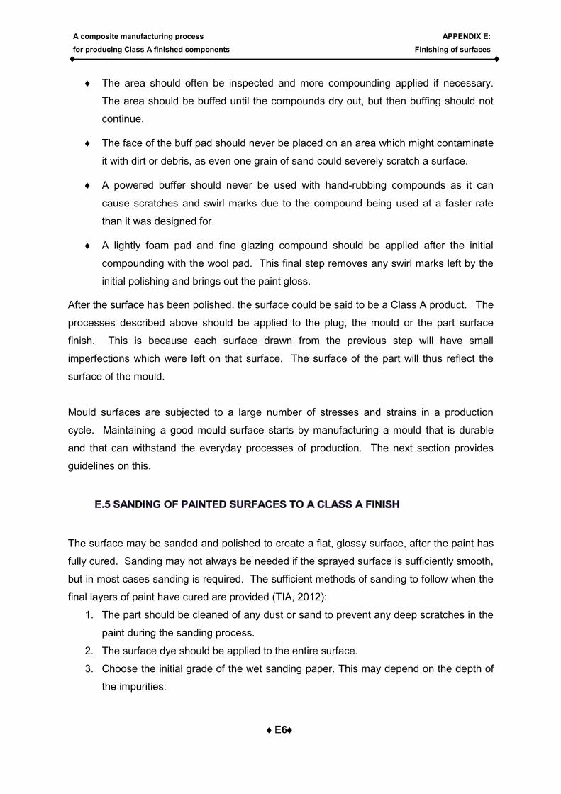
A composite manufacturing process
for producing Class A finished components
APPENDIX E:
Finishing of surfaces
E6
The area should often be inspected and more compounding applied if necessary.
The area should be buffed until the compounds dry out, but then buffing should not
continue.
The face of the buff pad should never be placed on an area which might contaminate
it with dirt or debris, as even one grain of sand could severely scratch a surface.
A powered buffer should never be used with hand-rubbing compounds as it can
cause scratches and swirl marks due to the compound being used at a faster rate
than it was designed for.
A lightly foam pad and fine glazing compound should be applied after the initial
compounding with the wool pad. This final step removes any swirl marks left by the
initial polishing and brings out the paint gloss.
After the surface has been polished, the surface could be said to be a Class A product. The
processes described above should be applied to the plug, the mould or the part surface
finish. This is because each surface drawn from the previous step will have small
imperfections which were left on that surface. The surface of the part will thus reflect the
surface of the mould.
Mould surfaces are subjected to a large number of stresses and strains in a production
cycle. Maintaining a good mould surface starts by manufacturing a mould that is durable
and that can withstand the everyday processes of production. The next section provides
guidelines on this.
The surface may be sanded and polished to create a flat, glossy surface, after the paint has
fully cured. Sanding may not always be needed if the sprayed surface is sufficiently smooth,
but in most cases sanding is required. The sufficient methods of sanding to follow when the
final layers of paint have cured are provided (TIA, 2012):
1. The part should be cleaned of any dust or sand to prevent any deep scratches in the
paint during the sanding process.
2. The surface dye should be applied to the entire surface.
3. Choose the initial grade of the wet sanding paper. This may depend on the depth of
the impurities:
A composite manufacturing process
for producing Class A finished components
APPENDIX E:
Finishing of surfaces
E7
a. To sand out orange peel on a gelcoat surface may require an initial grade of
P320 using a hard aluminium block.
b. To sand out orange peel on a 2K-paint surface may require an initial grade of
P600 using a hard aluminium block.
c. For sanding out very fine dust imperfections, a grade of P2000 may be used.
4. Sand the surface until all the impurities shown by the surface dye are removed,
always ensuring that the surface is wet.
5. After all impurities of one grade have been
removed, surface dye should be applied
again and the sanding of the next grade
should commence until a grade of P2000 is
reached. Each grade should be sanded at
a different angle opposed to the previous
grade, as illustrated in the Figure E-2.
After the surface has been sanded to a P2000 finish, it should be polished to obtain the
gloss recognised by Class A finishes.
Surface coat problems include a wide range of defects that can be found before or after
painting. To maintain repair quality and satisfy customers, one must be able to analyse and
correct finish problems efficiently (Duffy, 2004).
Surface coat defects usually originate as a result of problems in the preparation of the body
surface, painting procedure, environment, paint ingredients, and other sources;
Removal of foreign matter in wet paint
Paint foreign matter includes anything one can see in the paint that will adversely
affect the finish (dust, lint, hair, etc.). Upon noticing, try to remove immediately with
the aid of sharp tweezers, fine wire, tooth pick etc. After removal of debris, blend-
spray a coat of paint over the area right away.
Figure E-2: Directions of sanding to remove
marks of previous steps.(TIA, 2012)
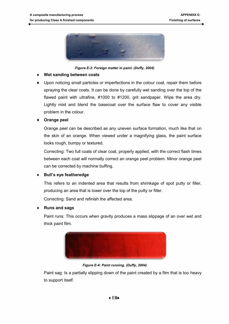
A composite manufacturing process
for producing Class A finished components
APPENDIX E:
Finishing of surfaces
E8
Figure E-3: Foreign matter in paint. (Duffy, 2004)
Wet sanding between coats
Upon noticing small particles or imperfections in the colour coat, repair them before
spraying the clear coats. It can be done by carefully wet sanding over the top of the
flawed paint with ultrafine, #1000 to #1200, grit sandpaper. Wipe the area dry.
Lightly mist and blend the basecoat over the surface flaw to cover any visible
problem in the colour.
Orange peel
Orange peel can be described as any uneven surface formation, much like that on
the skin of an orange. When viewed under a magnifying glass, the paint surface
looks rough, bumpy or textured.
Correcting: Two full coats of clear coat, properly applied, with the correct flash times
between each coat will normally correct an orange peel problem. Minor orange peel
can be corrected by machine buffing.
Bull’s eye featheredge
This refers to an indented area that results from shrinkage of spot putty or filler,
producing an area that is lower over the top of the putty or filler.
Correcting: Sand and refinish the affected area.
Runs and sags
Paint runs: This occurs when gravity produces a mass slippage of an over wet and
thick paint film.
Figure E-4: Paint running. (Duffy, 2004)
Paint sag: Is a partially slipping down of the paint created by a film that is too heavy
to support itself.
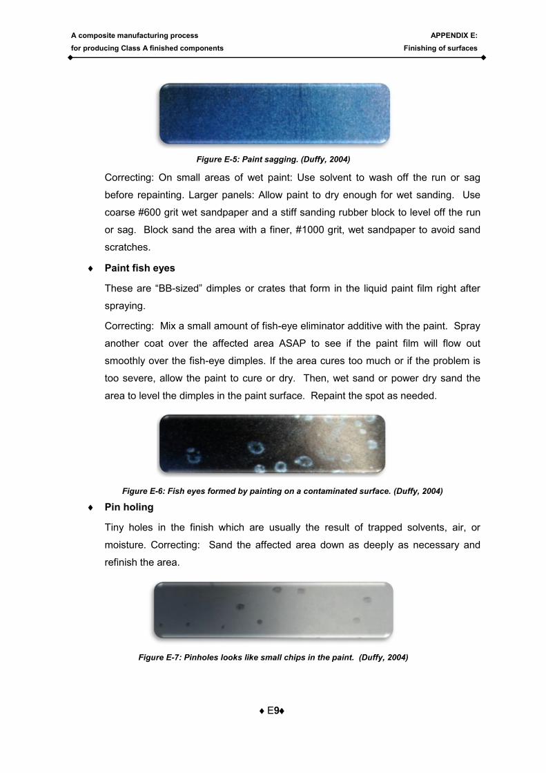
A composite manufacturing process
for producing Class A finished components
APPENDIX E:
Finishing of surfaces
E9
Figure E-5: Paint sagging. (Duffy, 2004)
Correcting: On small areas of wet paint: Use solvent to wash off the run or sag
before repainting. Larger panels: Allow paint to dry enough for wet sanding. Use
coarse #600 grit wet sandpaper and a stiff sanding rubber block to level off the run
or sag. Block sand the area with a finer, #1000 grit, wet sandpaper to avoid sand
scratches.
Paint fish eyes
These are “BB-sized” dimples or crates that form in the liquid paint film right after
spraying.
Correcting: Mix a small amount of fish-eye eliminator additive with the paint. Spray
another coat over the affected area ASAP to see if the paint film will flow out
smoothly over the fish-eye dimples. If the area cures too much or if the problem is
too severe, allow the paint to cure or dry. Then, wet sand or power dry sand the
area to level the dimples in the paint surface. Repaint the spot as needed.
Figure E-6: Fish eyes formed by painting on a contaminated surface. (Duffy, 2004)
Pin holing
Tiny holes in the finish which are usually the result of trapped solvents, air, or
moisture. Correcting: Sand the affected area down as deeply as necessary and
refinish the area.
Figure E-7: Pinholes looks like small chips in the paint. (Duffy, 2004)
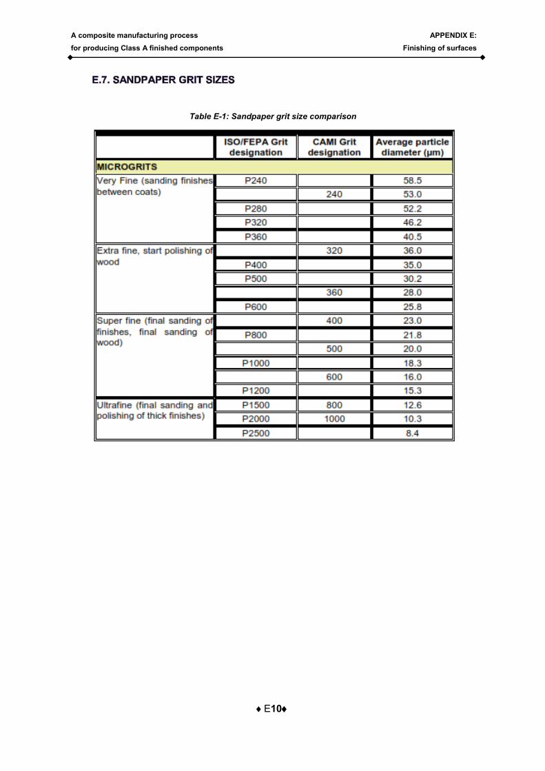
A composite manufacturing process
for producing Class A finished components
APPENDIX E:
Finishing of surfaces
E10
Table E-1: Sandpaper grit size comparison
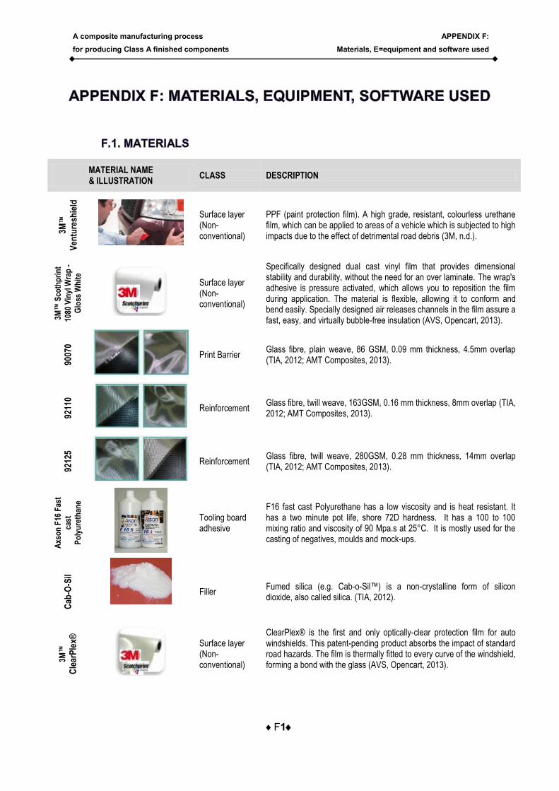
A composite manufacturing process
for producing Class A finished components
APPENDIX F:
Materials, E=equipment and software used
F1
MATERIAL NAME & ILLUSTRATION
CLASS DESCRIPTION
3M™
Ven
ture
shie
ld
Surface layer (Non-conventional)
PPF (paint protection film). A high grade, resistant, colourless urethane film, which can be applied to areas of a vehicle which is subjected to high impacts due to the effect of detrimental road debris (3M, n.d.).
3M™
Sco
thp
rin
t
1080
Vin
yl W
rap
-
Glo
ss W
hit
e
Surface layer (Non-conventional)
Specifically designed dual cast vinyl film that provides dimensional stability and durability, without the need for an over laminate. The wrap's adhesive is pressure activated, which allows you to reposition the film during application. The material is flexible, allowing it to conform and bend easily. Specially designed air releases channels in the film assure a fast, easy, and virtually bubble-free insulation (AVS, Opencart, 2013).
9007
0
Print Barrier Glass fibre, plain weave, 86 GSM, 0.09 mm thickness, 4.5mm overlap (TIA, 2012; AMT Composites, 2013).
9211
0
Reinforcement Glass fibre, twill weave, 163GSM, 0.16 mm thickness, 8mm overlap (TIA, 2012; AMT Composites, 2013).
9212
5
Reinforcement Glass fibre, twill weave, 280GSM, 0.28 mm thickness, 14mm overlap (TIA, 2012; AMT Composites, 2013).
Axs
on
F16
Fas
t
cast
Po
lyu
reth
ane
Tooling board adhesive
F16 fast cast Polyurethane has a low viscosity and is heat resistant. It has a two minute pot life, shore 72D hardness. It has a 100 to 100 mixing ratio and viscosity of 90 Mpa.s at 25°C. It is mostly used for the casting of negatives, moulds and mock-ups.
Cab
-O-S
il
Filler Fumed silica (e.g. Cab-o-Sil™) is a non-crystalline form of silicon dioxide, also called silica. (TIA, 2012).
3M™
Cle
arP
lex®
Surface layer (Non-conventional)
ClearPlex® is the first and only optically-clear protection film for auto windshields. This patent-pending product absorbs the impact of standard road hazards. The film is thermally fitted to every curve of the windshield, forming a bond with the glass (AVS, Opencart, 2013).
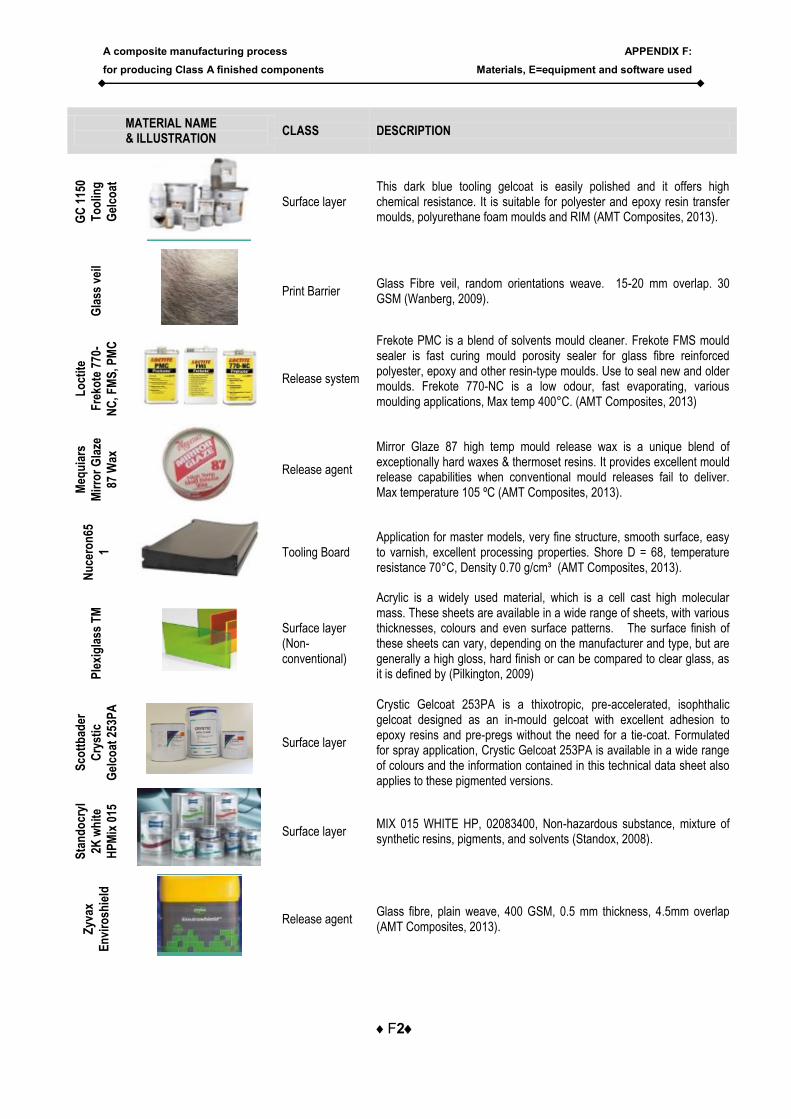
A composite manufacturing process
for producing Class A finished components
APPENDIX F:
Materials, E=equipment and software used
F2
MATERIAL NAME & ILLUSTRATION
CLASS DESCRIPTION
GC
115
0
To
olin
g
Gel
coat
Surface layer This dark blue tooling gelcoat is easily polished and it offers high chemical resistance. It is suitable for polyester and epoxy resin transfer moulds, polyurethane foam moulds and RIM (AMT Composites, 2013).
Gla
ss v
eil
Print Barrier Glass Fibre veil, random orientations weave. 15-20 mm overlap. 30 GSM (Wanberg, 2009).
Lo
ctit
e
Fre
kote
770
-
NC
, FM
S, P
MC
Release system
Frekote PMC is a blend of solvents mould cleaner. Frekote FMS mould sealer is fast curing mould porosity sealer for glass fibre reinforced polyester, epoxy and other resin-type moulds. Use to seal new and older moulds. Frekote 770-NC is a low odour, fast evaporating, various moulding applications, Max temp 400°C. (AMT Composites, 2013)
Meq
uia
rs
Mir
ror
Gla
ze
87 W
ax
Release agent
Mirror Glaze 87 high temp mould release wax is a unique blend of exceptionally hard waxes & thermoset resins. It provides excellent mould release capabilities when conventional mould releases fail to deliver. Max temperature 105 ºC (AMT Composites, 2013).
Nu
cero
n65
1
Tooling Board Application for master models, very fine structure, smooth surface, easy to varnish, excellent processing properties. Shore D = 68, temperature resistance 70°C, Density 0.70 g/cm³ (AMT Composites, 2013).
Ple
xig
lass
TM
Surface layer (Non-conventional)
Acrylic is a widely used material, which is a cell cast high molecular mass. These sheets are available in a wide range of sheets, with various thicknesses, colours and even surface patterns. The surface finish of these sheets can vary, depending on the manufacturer and type, but are generally a high gloss, hard finish or can be compared to clear glass, as it is defined by (Pilkington, 2009)
Sco
ttb
ader
Cry
stic
Gel
coat
253
PA
Surface layer
Crystic Gelcoat 253PA is a thixotropic, pre-accelerated, isophthalic gelcoat designed as an in-mould gelcoat with excellent adhesion to epoxy resins and pre-pregs without the need for a tie-coat. Formulated for spray application, Crystic Gelcoat 253PA is available in a wide range of colours and the information contained in this technical data sheet also applies to these pigmented versions.
Sta
nd
ocr
yl
2K w
hit
e
HP
Mix
015
Surface layer MIX 015 WHITE HP, 02083400, Non-hazardous substance, mixture of synthetic resins, pigments, and solvents (Standox, 2008).
Zyv
ax
En
viro
shie
ld
Release agent Glass fibre, plain weave, 400 GSM, 0.5 mm thickness, 4.5mm overlap (AMT Composites, 2013).

A composite manufacturing process
for producing Class A finished components
APPENDIX F:
Materials, E=equipment and software used
F3
MATERIAL NAME & ILLUSTRATION
CLASS DESCRIPTION
Zyv
ax S
eale
r
GP
Release system sealer
Universal solvent-free release agent designed specifically to meet the “green chemistry” requirements, Thermal stability: 260 ºC, High gloss, high slip / lubricity, No build-up on mould. No transfer to mould (AMT Composites, 2013).
Zyv
ax F
lex-
Z1,
Z3
Release agent
High modulus, clear, flexible film with superior substrate adhesion that forms a protective shield on the mould or tool surface. As a conditioner, designed to treat both the chemical and physical bonding sites (AMT Composites, 2013).
Zyv
ax N
ano
Release agent
A variable release system that gives total control to the moulder. Thermal stability: 480 °C. Z1: minimum slip; Iinhibits pre-release and promotes tape adhesion. Prevents styrene build up. Z3: medium slip, standard choice for large hulls and flat areas (AMT Composites, 2013).
Zyv
ax
Wat
ercl
ean
Release system cleaner
Nano release high performance coating is a breakthrough in green chemistry based on non-polluting, odour-free Nano E.G.O. polymer technology. Hazard-free and user safe (AMT Composites, 2013).
EQUIPMENT NAME & ILLUSTRATION
CLASS DESCRIPTION
3M
wet
ord
ryT
M
Sanding Paper 3M wet or dry TM sanding paper GRIT P400 to P3000. COLAD foam sanding pads - medium, fine.
BA
LL
NO
SE
Ø6m
m
Equipment CNC ball nose finishing tool. CARBIDE, JS internal code none, d=6mm, r=3mm, L=131.15mm, I=10mm, Le=17.5mm, P=0mm
EN
D M
ILL
Ø12
mm
CNC End mill roughing tool. CARBIDE, JS internal code M30120CN, d=12mm, r=0mm, L=101mm, I=55mm, Le=59mm, P=0mm
EN
D M
ILL
Ø40
mm
Equipment CNC End mill roughing tool. CARBIDE, JS internal code M00450AR, d=40mm, r=0mm, L=128.42mm, I=29mm, Le=54mm, P=0mm
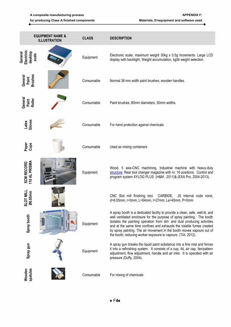
A composite manufacturing process
for producing Class A finished components
APPENDIX F:
Materials, E=equipment and software used
F4
EQUIPMENT NAME & ILLUSTRATION
CLASS DESCRIPTION
Gen
eral
Ele
ctri
nic
des
kto
p
scal
e
Equipment Electronic scale, maximum weight 30kg x 0.5g increments. Large LCD display with backlight, Weight accumulation, kg/lb weight selection.
Gen
eral
Pai
nt
Bru
shes
Consumable Normal 38 mm width paint brushes, wooden handles.
Gen
eral
Pai
nt
Ro
ller
Consumable Paint brushes, 80mm diameters, 50mm widths.
Lat
ex
Glo
ves
Consumable For hand protection against chemicals
Pap
er
Cu
ps
Consumable Used as mixing containers
SC
M R
EC
OR
D
110
AL
PR
ISM
A
Equipment Wood, 5 axis-CNC machining, Industrial machine with heavy-duty structure. Rear tool changer magazine with nr. 16 positions. Control and program system XYLOG PLUS (H&M , 2011)& (EXA Pro, 2004-2013).
SL
OT
MIL
L
Ø6.
05m
m
CNC Slot mill finishing tool. CARBIDE, JS internal code none, d=6.05mm, r=0mm, L=64mm, I=27mm, Le=45mm, P=0mm
Sp
ray
bo
oth
Equipment
A spray booth is a dedicated facility to provide a clean, safe, well-lit, and well ventilated enclosure for the purpose of spray painting. The booth isolates the painting operation from dirt- and dust producing activities and at the same time confines and exhausts the volatile fumes created by spray painting. The air movement in the booth moves vapours out of the booth, reducing worker exposure to vapours (TIA, 2012).
Sp
ray
gu
n
Equipment
A spray gun breaks the liquid paint substance into a fine mist and forces it into a refinishing system. It consists of a cup, lid, air cap, fan/pattern adjustment, flow adjustment, handle and air inlet. It is operated with air pressure (Duffy, 2004).
Wo
od
en
spat
ula
s
Consumable For mixing of chemicals
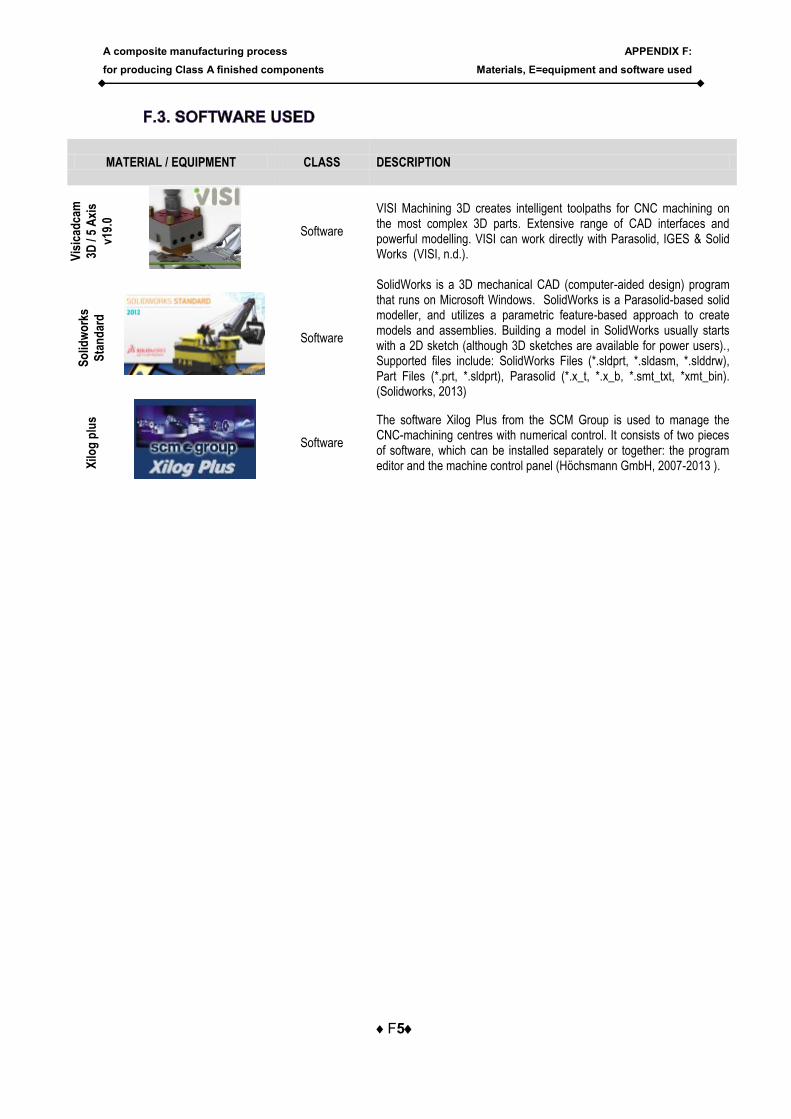
A composite manufacturing process
for producing Class A finished components
APPENDIX F:
Materials, E=equipment and software used
F5
MATERIAL / EQUIPMENT CLASS DESCRIPTION
Vis
icad
cam
3D /
5 A
xis
v19.
0
Software
VISI Machining 3D creates intelligent toolpaths for CNC machining on the most complex 3D parts. Extensive range of CAD interfaces and powerful modelling. VISI can work directly with Parasolid, IGES & Solid Works (VISI, n.d.).
So
lidw
ork
s
Sta
nd
ard
Software
SolidWorks is a 3D mechanical CAD (computer-aided design) program that runs on Microsoft Windows. SolidWorks is a Parasolid-based solid modeller, and utilizes a parametric feature-based approach to create models and assemblies. Building a model in SolidWorks usually starts with a 2D sketch (although 3D sketches are available for power users)., Supported files include: SolidWorks Files (*.sldprt, *.sldasm, *.slddrw), Part Files (*.prt, *.sldprt), Parasolid (*.x_t, *.x_b, *.smt_txt, *xmt_bin). (Solidworks, 2013)
Xilo
g p
lus
Software
The software Xilog Plus from the SCM Group is used to manage the CNC-machining centres with numerical control. It consists of two pieces of software, which can be installed separately or together: the program editor and the machine control panel (Höchsmann GmbH, 2007-2013 ).
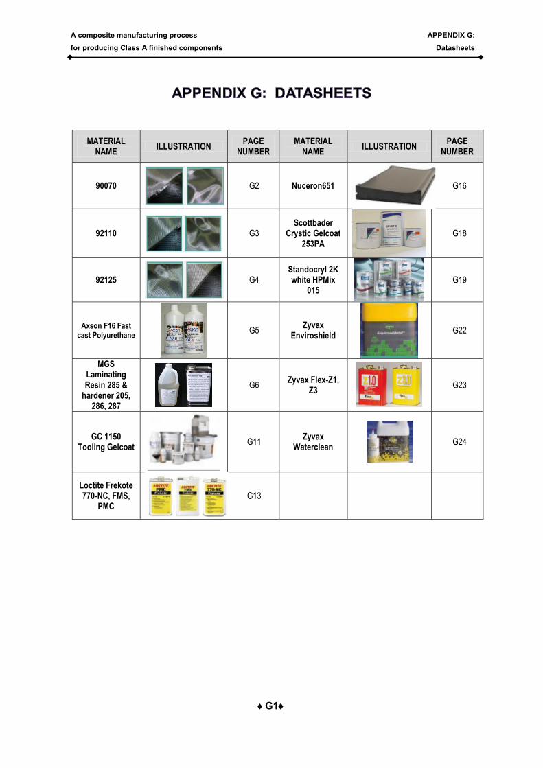
A composite manufacturing process
for producing Class A finished components
APPENDIX G:
Datasheets
G1
MATERIAL NAME
ILLUSTRATION PAGE
NUMBER MATERIAL
NAME ILLUSTRATION
PAGE NUMBER
90070
G2 Nuceron651
G16
92110
G3 Scottbader
Crystic Gelcoat 253PA
G18
92125
G4 Standocryl 2K white HPMix
015
G19
Axson F16 Fast cast Polyurethane
G5 Zyvax
Enviroshield
G22
MGS Laminating Resin 285 &
hardener 205, 286, 287
G6 Zyvax Flex-Z1,
Z3
G23
GC 1150 Tooling Gelcoat
G11 Zyvax
Waterclean
G24
Loctite Frekote 770-NC, FMS,
PMC
G13
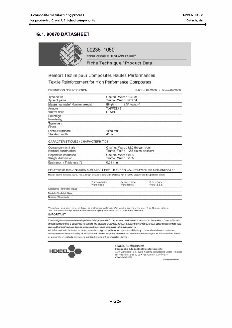
A composite manufacturing process
for producing Class A finished components
APPENDIX G:
Datasheets
G2
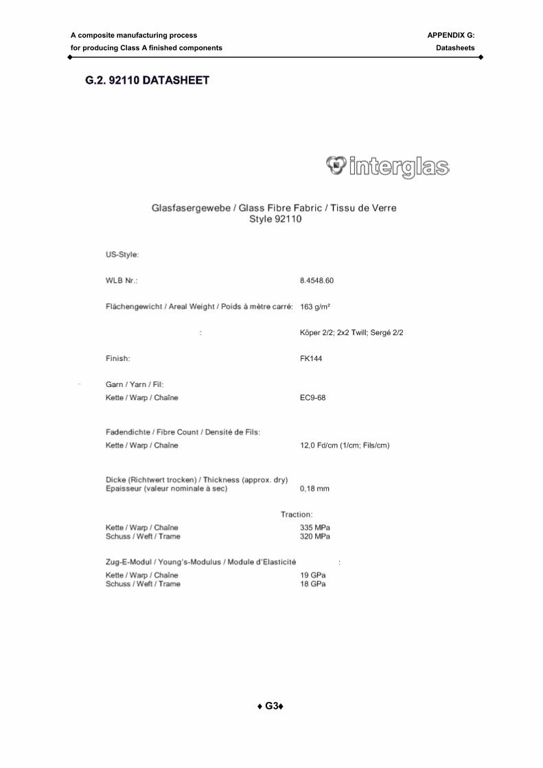
A composite manufacturing process
for producing Class A finished components
APPENDIX G:
Datasheets
G3
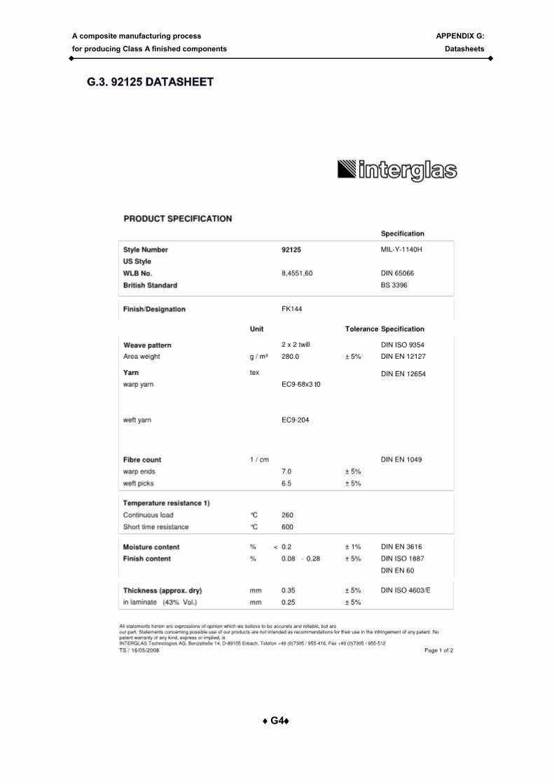
A composite manufacturing process
for producing Class A finished components
APPENDIX G:
Datasheets
G4
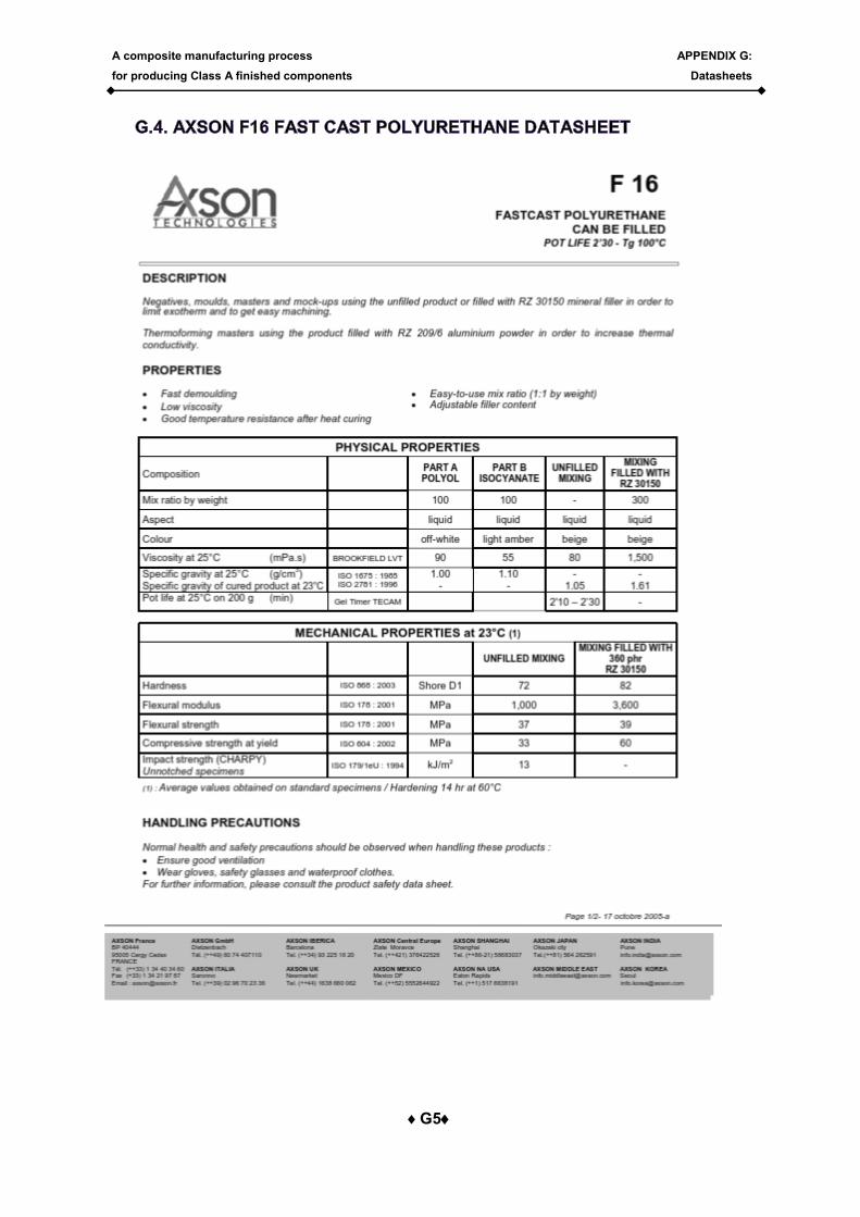
A composite manufacturing process
for producing Class A finished components
APPENDIX G:
Datasheets
G5
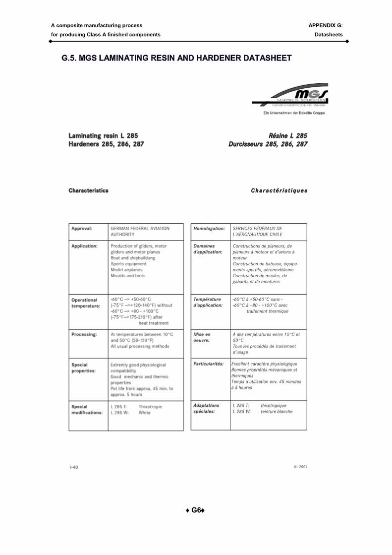
A composite manufacturing process
for producing Class A finished components
APPENDIX G:
Datasheets
G6

A composite manufacturing process
for producing Class A finished components
APPENDIX G:
Datasheets
G7
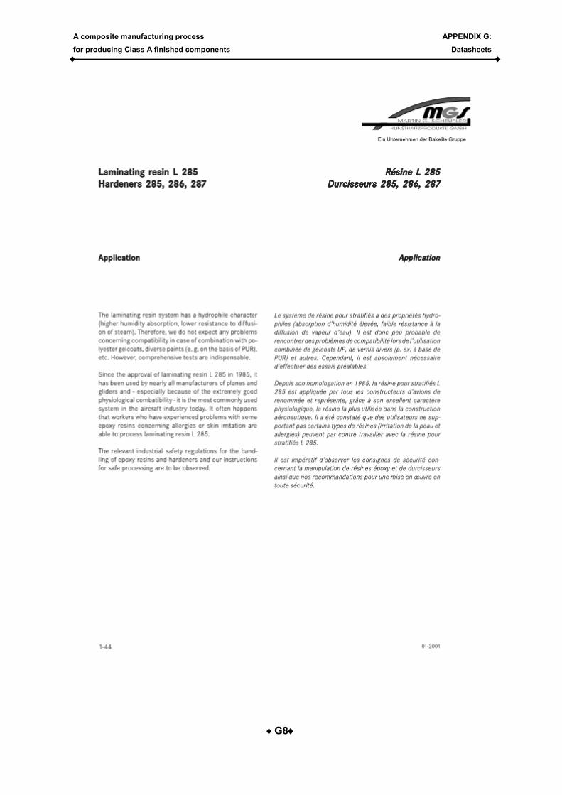
A composite manufacturing process
for producing Class A finished components
APPENDIX G:
Datasheets
G8
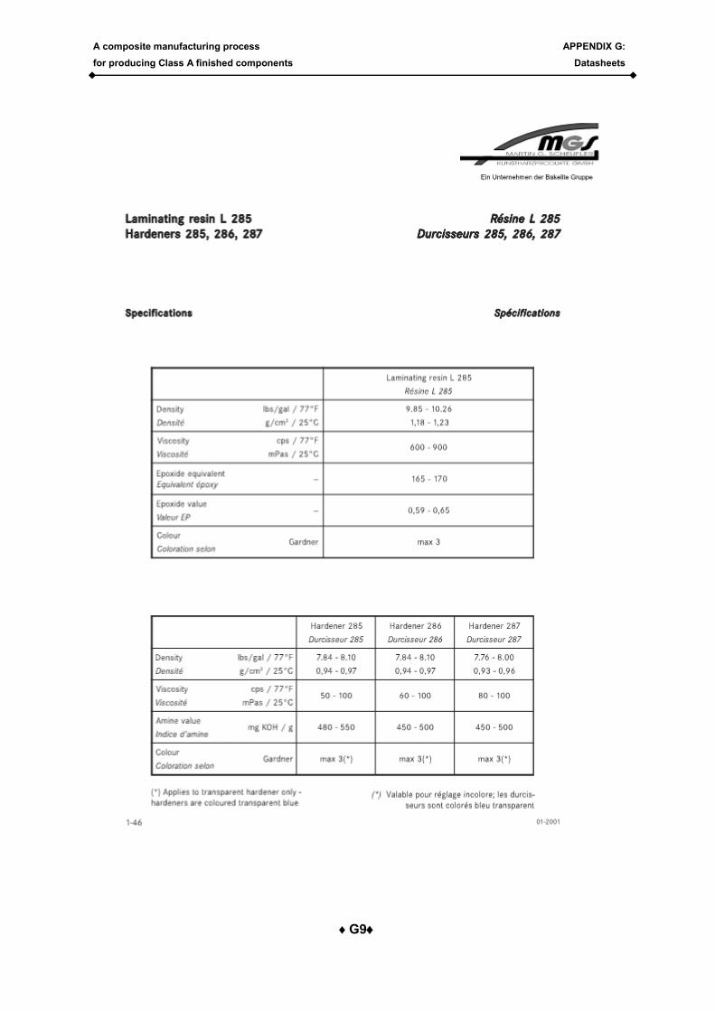
A composite manufacturing process
for producing Class A finished components
APPENDIX G:
Datasheets
G9
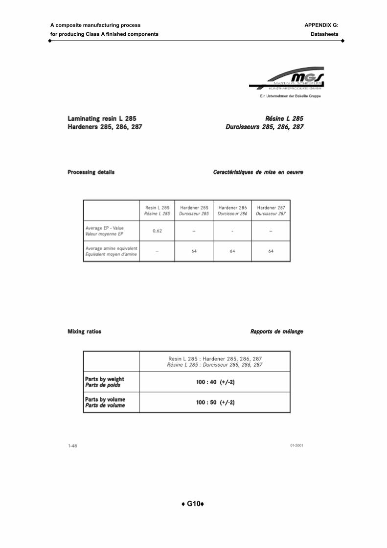
A composite manufacturing process
for producing Class A finished components
APPENDIX G:
Datasheets
G10
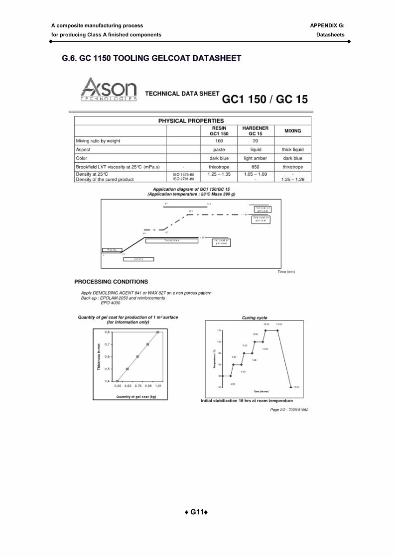
A composite manufacturing process
for producing Class A finished components
APPENDIX G:
Datasheets
G11
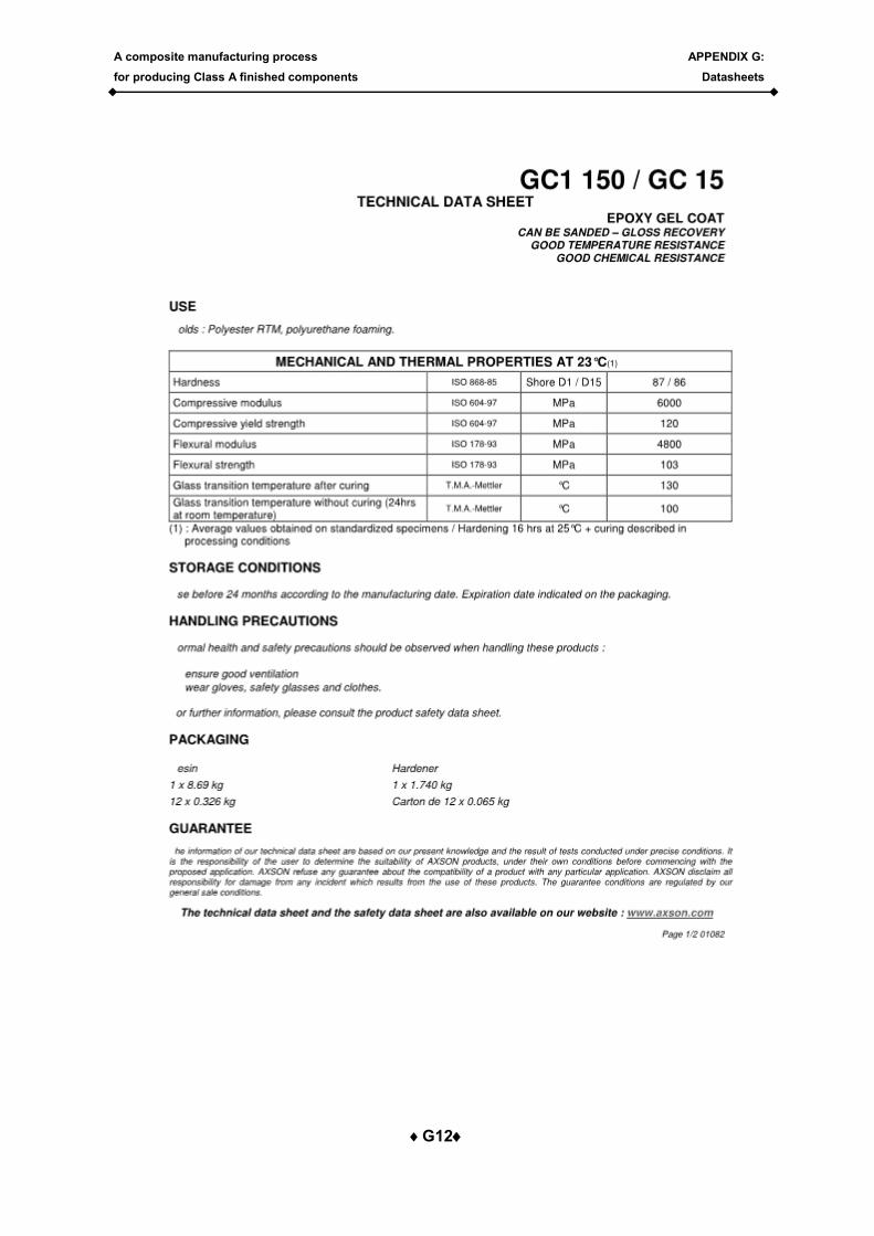
A composite manufacturing process
for producing Class A finished components
APPENDIX G:
Datasheets
G12
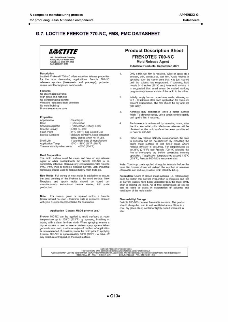
A composite manufacturing process
for producing Class A finished components
APPENDIX G:
Datasheets
G13
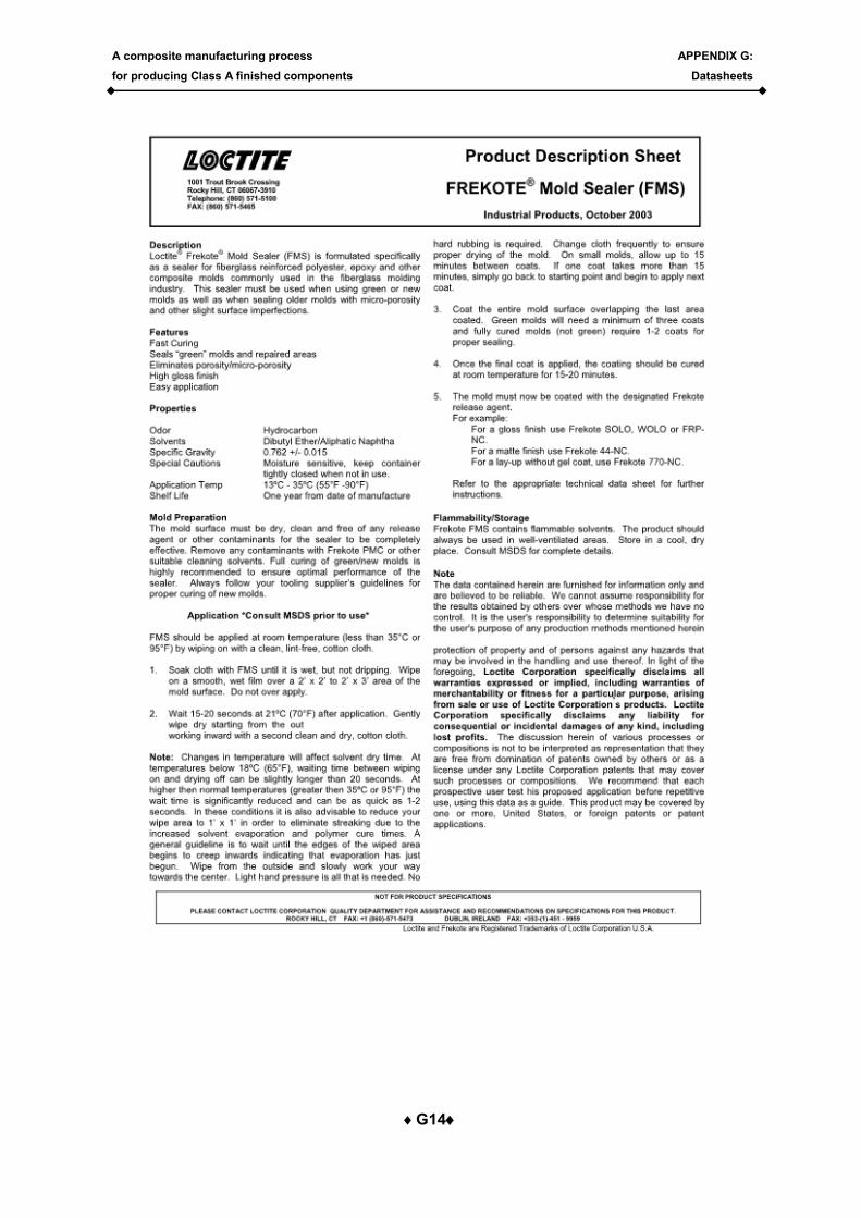
A composite manufacturing process
for producing Class A finished components
APPENDIX G:
Datasheets
G14
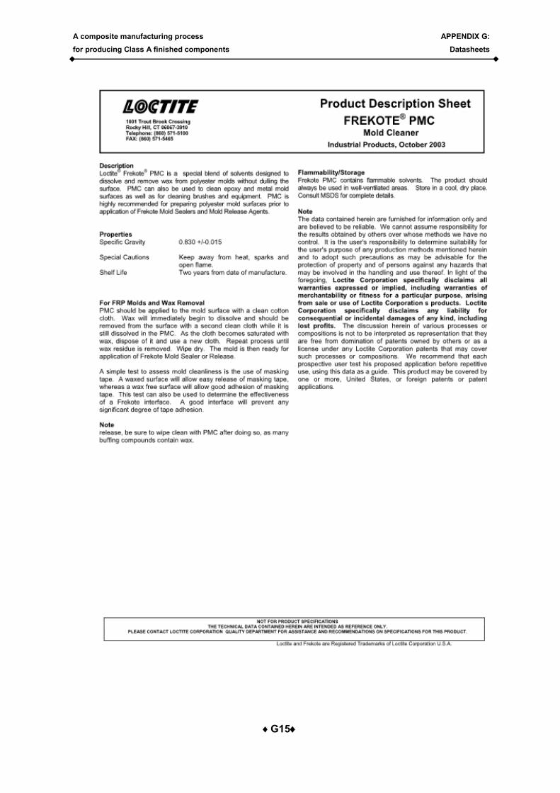
A composite manufacturing process
for producing Class A finished components
APPENDIX G:
Datasheets
G15
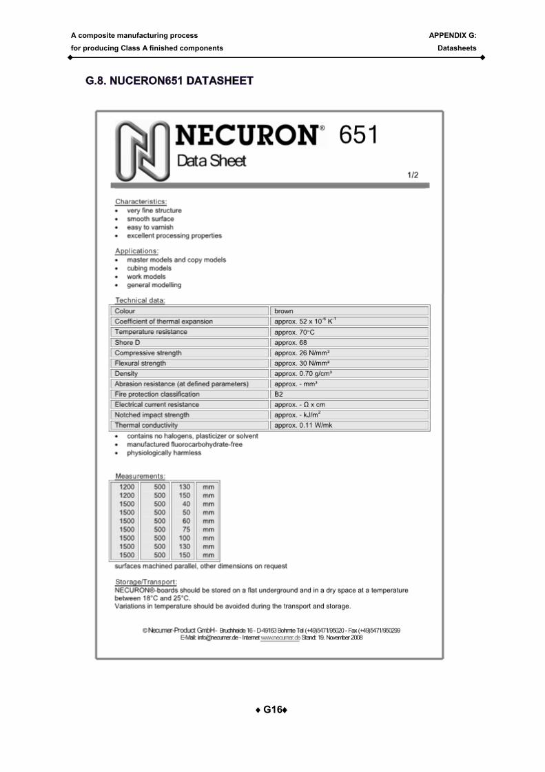
A composite manufacturing process
for producing Class A finished components
APPENDIX G:
Datasheets
G16

A composite manufacturing process
for producing Class A finished components
APPENDIX G:
Datasheets
G17
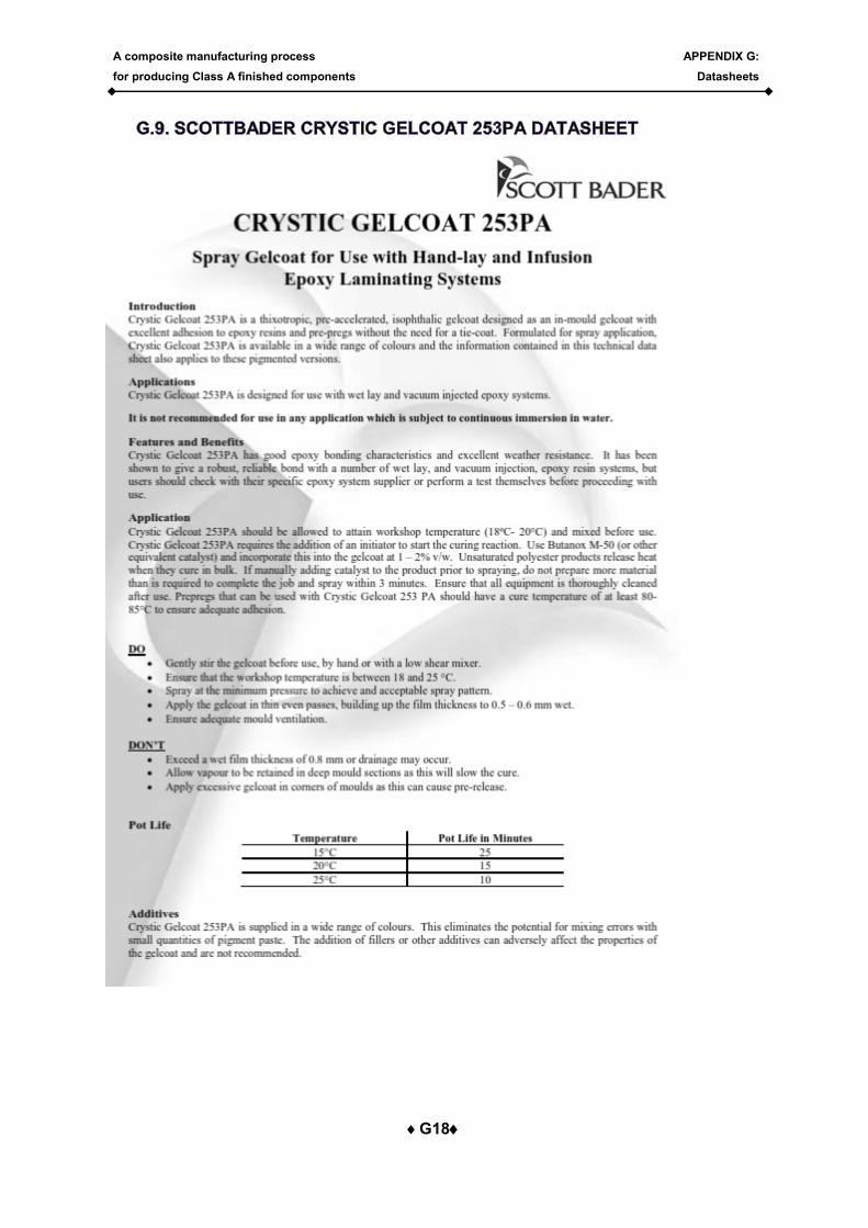
A composite manufacturing process
for producing Class A finished components
APPENDIX G:
Datasheets
G18
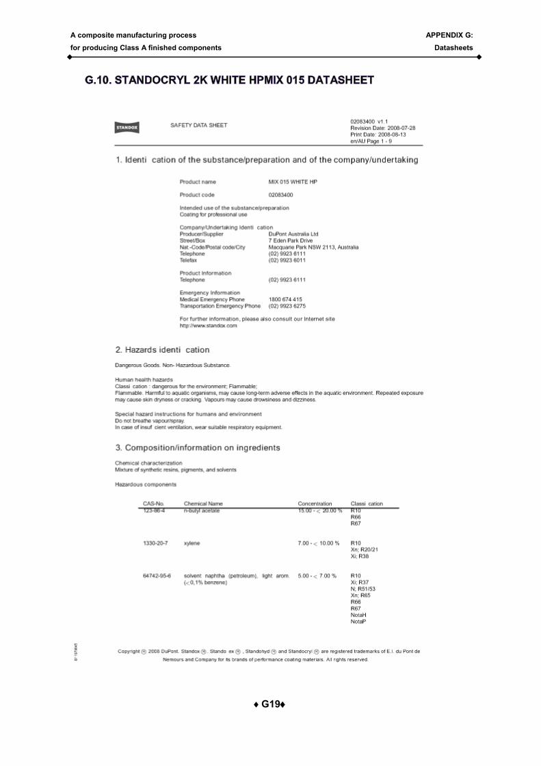
A composite manufacturing process
for producing Class A finished components
APPENDIX G:
Datasheets
G19
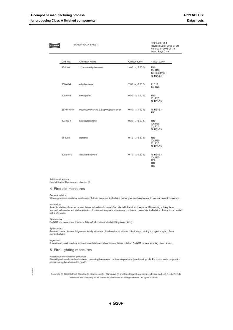
A composite manufacturing process
for producing Class A finished components
APPENDIX G:
Datasheets
G20
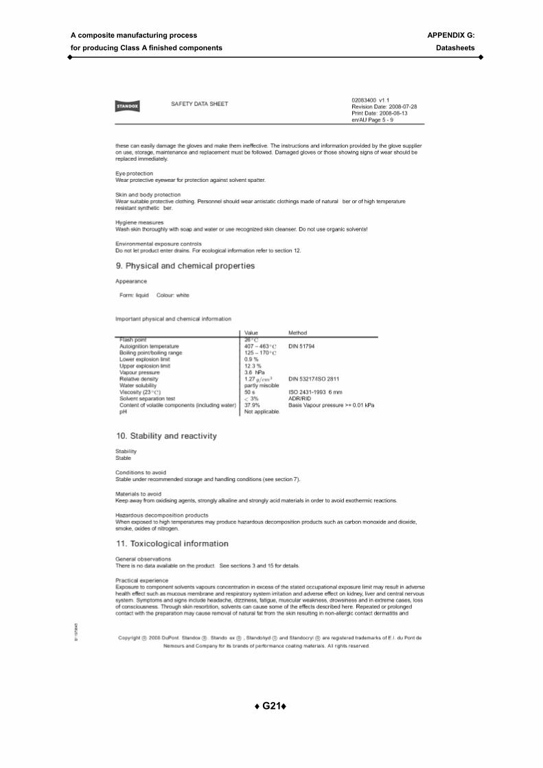
A composite manufacturing process
for producing Class A finished components
APPENDIX G:
Datasheets
G21
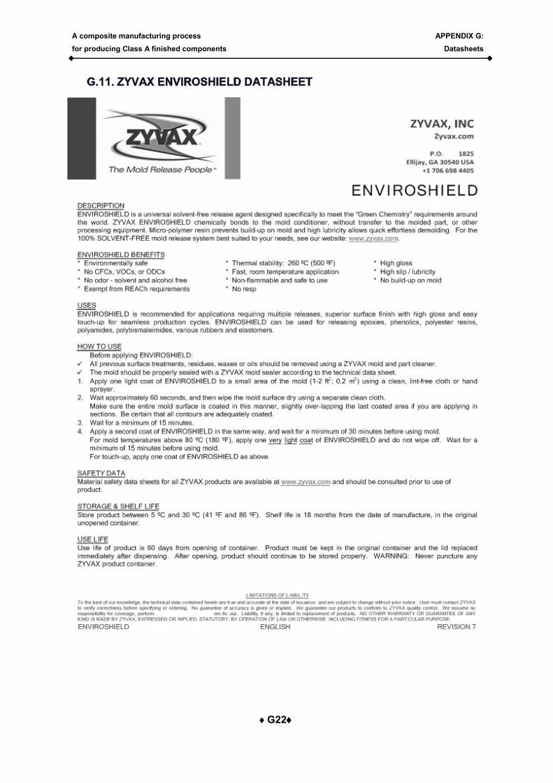
A composite manufacturing process
for producing Class A finished components
APPENDIX G:
Datasheets
G22
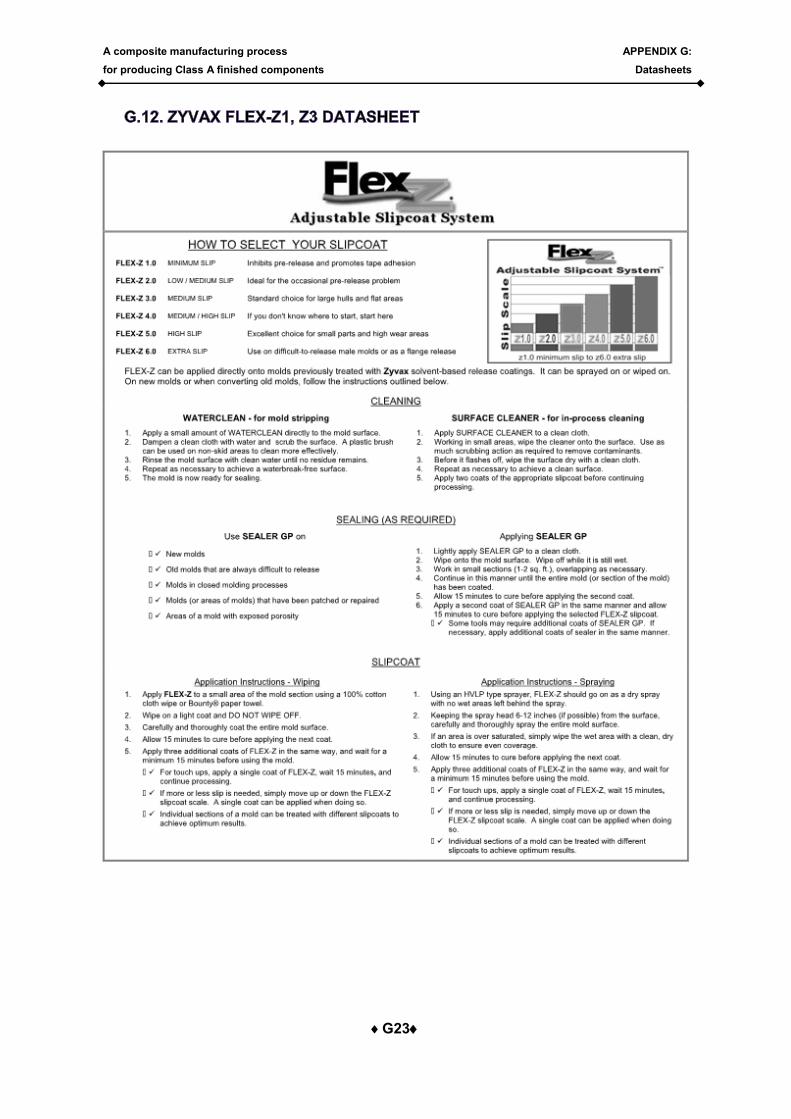
A composite manufacturing process
for producing Class A finished components
APPENDIX G:
Datasheets
G23
A composite manufacturing process
for producing Class A finished components
APPENDIX G:
Datasheets
G24
A composite manufacturing process
for producing Class A finished components
APPENDIX G:
Datasheets
G25
Recommended