Energy System Initiative
March 6, 2011
Reduced Order Modeling for CFD Units
Yidong Lang1,2, Stephen E. Zitney2 and Lorenz T. Biegler* 1,2
1Department of Chemical Engineering Carnegie Mellon University
Pittsburgh, PA
2Collaboratory for Process & Dynamic Systems Research National Energy Technology Laboratory
Morgantown, WV

3/9/11 14:34 2
Outline
• Mo=va=on • Development of PCA based ROM • Valida=ons of ROMs • Encapsulate yROM as Unit Module in Process
simulator, e.g. USER3 Model in Aspen Plus • Integra=ng the USER3 with IGCC in Aspen Plus for
Process Op=miza=on with EO mode • Conclusions

3/9/11 14:34 3
Extending Concepts of APECS: Co‐Simula=on into Process Op=miza=on
CFD Model
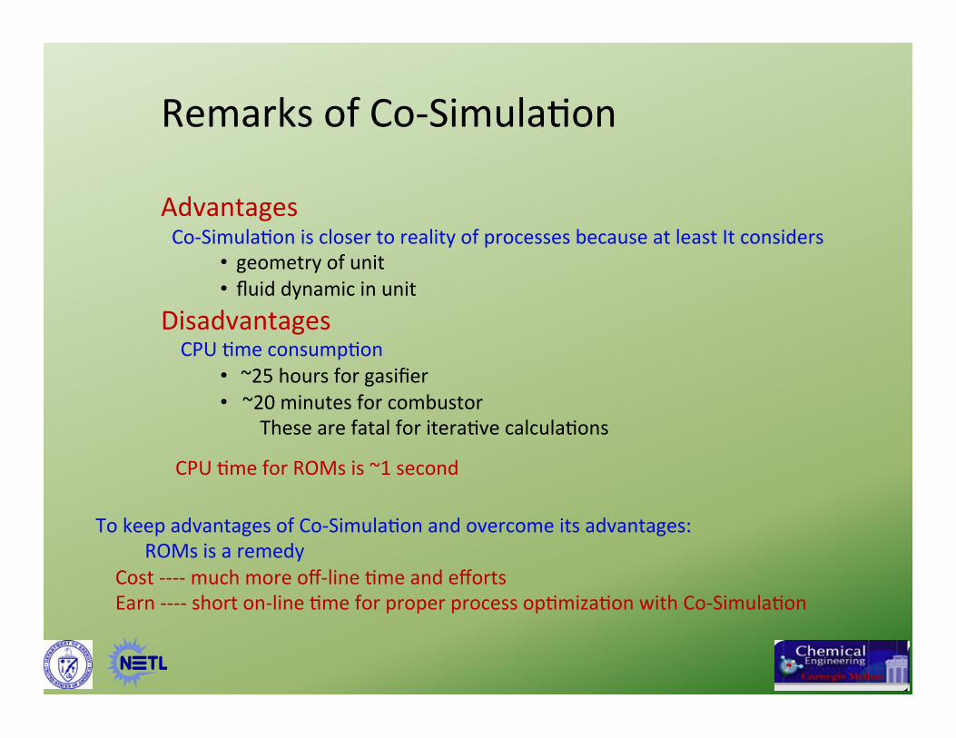
Remarks of Co‐Simula=on Advantages Co‐Simula=on is closer to reality of processes because at least It considers
• geometry of unit • fluid dynamic in unit
Disadvantages CPU =me consump=on
• ~25 hours for gasifier • ~20 minutes for combustor
These are fatal for itera=ve calcula=ons
CPU =me for ROMs is ~1 second
To keep advantages of Co‐Simula=on and overcome its advantages: ROMs is a remedy Cost ‐‐‐‐ much more off‐line =me and efforts Earn ‐‐‐‐ short on‐line =me for proper process op=miza=on with Co‐Simula=on

5
p
j
in
in
i fPT
u ℜ∈
=
)(mqi v
PT
X ℜ∈
=
=
nco
j
out
out
i
d
dPT
Y
Input Space
np×ℜ∈u
YX
ROM u:
ROM is a mapping
from input space into state space and output space
)( nmqX ×ℜ∈
State Space
Output Space
Y
5

3/9/11 14:34 6
ROM Development for CFD Model
Ref: Yidong Lang et al., Reduced Order Model Based on Principal Component Analysis for
Process Simula=on and Op=miza=on†, Energy & Fuels 2009, 23, 1695–1706
xROM PCA ROM
yROM For Iterative process simulation and optimization
Display fields of states after convergence Cases of
CFD Model
ROM is a remedy to overcome CPU =me prohibited of CFD model in itera=ve compu=ng of co‐simulated flowsheet simula=on and op=miza=on

Procedures for ROM development
1. Domain determina=on 2. Experimental design (LHS) 3. Run CFD models to obtain a set of snapshots with outputs 4. Implement the set with PCA (Principal Component Analysis) 5. Regression:
• NNET (Neural Network) • Kriging (Geosta=s=cal Technique)
u⋅
=
⇒
)()(
00
)()(
uwuv
IP
uYuX
yROMxROM

8
Entrained-Flow Coal Gasifier
Entrained‐flow Gasifier, its typical temperature profile, meshed with Fluent and interest area
Lower bound Shi’s value Upper bound
u1 25 30 35
u2 0.75 0.817 0.85
u3 70 78 85
Opera0on Window of Gasifier u1 ‐‐‐ the percentage of coal to inject between stage one and stage two; u2 ‐‐‐ the water percentage in the slurry; u3 ‐‐‐ the oxygen/coal feed ra=o.
N > 12,000
n=225

9
Valida0on of xROM for Gasifier
Contour plots of seven state variables for an example case. The le; figure in each set is the
FLUENT result, while the right figure is the ROM predicDon.

Gas turbine combustor
Geometry & mesh of the combustor
Typical temperature field in the combustor
N = 5996
Interest area of temperature field
N’ = 2601
10
11
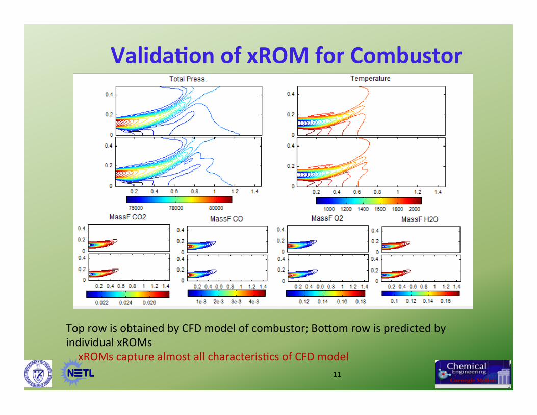
Top row is obtained by CFD model of combustor; Bomom row is predicted by individual xROMs xROMs capture almost all characteris=cs of CFD model
Valida0on of xROM for Combustor

3/9/11 12
Sta=s=cs of Cross‐Valida=on for yROMs
yROM of Combustor 896 data points (128 cases, 7 variables) relative errors of all prediction are < 1.0%, except one is up to 1.7%.
yROM of Gasifier: 196 data points (28 cases, 7 outputs) Relative erros of predictions: H2S & Temp 100% data points < 1.0% CO2 : 15% is within 1.0% and 60% within 5.0%. Cause: Discrete Phase Model (DMP) was used
ji
jijiji y
yyrlerr
,
,,,
|ˆ| −=

13
AIR
FUEL
LP CONS . MP
CONS . HP CONS .
CW
DW
High Pressure ( HP ) Header
Vacuum Header Condensate
Header
Medium Pressure ( MP ) Header
Low Pressure ( LP ) Header
Deaerator
HRSG
Gas Turbine
S 1 S 58
S 2
S 3
S 59
S 4
S 60
S 61
S 5
S 6 S 7
S 8
S 9
S 15 S 20
S 16 S 12
S 11 S 17 S 10 S 37 S 38
S 34 S 35 S 36
S 41 S 46
S 43
S 42
S 45
S 40
S 39 S 47 S 54
Gas
ifier
wat
er
Coa
l
O2
Flowsheet for Closed Loop Tes0ng Integra=ng yROM of Gasifier and Steam Cycle
14
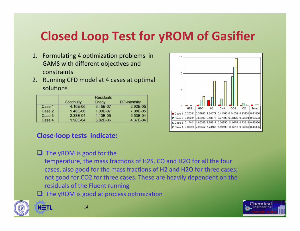
Closed Loop Test for yROM of Gasifier
0
5
10
15
Case 1 0.20311 0.37995 1.84072 0.41165 0.44552 0.23151 0.41060
Case 2 0.02011 0.62983 0.48576 2.27500 9.08430 0.93594 0.03693
Case 3 0.17401 1.80365 2.76817 0.06850 11.9952 0.73518 0.45936
Case 4 0.09924 2.96652 7.73165 7.59190 14.6513 0.33569 0.48395
H2S H2O H2 CH4 CO2 CO Temp
Close‐loop tests indicate: The yROM is good for the temperature, the mass frac=ons of H2S, CO and H2O for all the four cases, also good for the mass frac=ons of H2 and H2O for three cases; not good for CO2 for three cases. These are heavily dependent on the residuals of the Fluent running The yROM is good at process op=miza=on
Residuals Continuity Enegy DO-intensity
Case 1 4.10E-06 6.45E-07 2.92E-05 Case 2 9.48E-06 1.09E-07 7.98E-05 Case 3 2.33E-04 4.10E-05 5.53E-04 Case 4 1.98E-04 6.82E-06 4.37E-04
1. Formula=ng 4 op=miza=on problems in GAMS with different objec=ves and constraints
2. Running CFD model at 4 cases at op=mal solu=ons

We are confident to invoke ROMs in process op=miza=on
yROM must be encapsulated
EO (Equa=on Oriented) mode defined as User3 modeling in Aspen Plus is chosen for its poten=al advantages (e.q. more NLP solver
such as IPOPT are available)

Gasifier model and its vicinity Combustor model and its vicinity
yROMs Wrapped as USER3 models with protocol of Aspen Plus

17
TNO‐IGCC and integra=on of replaced CFD models
Water shio
TSA and CO2 compress
Gas‐Combustor‐Turbine
Steam cycle
Gasif
USER3
Cmbst USER3

Starting point Optimal solution [NLP 5] [NLP 6]
Net-work-of-gas- turbine[MWe] 225.338 228.143 228.270 WCMP -73.846 -73.843 -73.844 W04 299.184 301.986 302.114 SC-w-tot [MWe] 116.095 129.626 136.382 W07 23.828 26.832 30.045 W09 27.383 30.227 31.059 W10-1 37.130 41.239 42.579 W10-2 31.678 35.252 36.475 Wpump -3.925 -3.925 -3.775 Power output of plant [MWe] 341.433 357.768 364.652 No. of iterations 8 15 CPU time [sec] 1.37 2.38 Independents Gasifier_Ratio (R1) [%] 80.2601 70.3411 70.3411 Gasifier_Ratio (R2)[%] 26.2087 31.4308 30.7035 Gasifier_Ratio (R3)[%] 84.8813 84.8813 84.8813 Split ratio of MC301[%] 24.0000 24.0036 24.0047 Split ratio of Q8 [%] 60.0 --- 70 Mass flow of Stream 413 [kg/hr] 750,000 --- 721,417 Mass flow of WGS Feed [kg/hr] 245,023 --- 239,500
Optimal solutions
[NLP 5] --- 4 independents related to yROMs only [NLP 6] ---- 3 additional independent inserted to [NLP 5] Optimal solutions increase net power output [NLP 5] 4.8 % or 16.34 MWe [NLP 6] 6.8 % or 23.22 MWe 6.88 MWe

19
Conclusions • The concept of APECS is extended to process op=miza=on by replacing CFD model
with its PCA ROM in IGCC flowsheet. • ROMs for gasifier and combustor are developed and validated. • ‘Close loop’ tests with ROM of gasifier in GAMS show that valida=on from converged
Fluent case is encouraging. • Conversion from yROMs into USER3 models are successfully implemented and can
be integrated with an exis=ng TNO‐IGCC flowsheet. • Stand alone tests verified that the user3 models of the gasifier and the combustor
could be confident for op=miza=on. • Op=miza=on of TNO‐IGCC process with the ‘black box’ showed interes=ng benefit
that the efficiency of IGCC could increase 5‐7 % by primarily op=mizing the process. • We have been aiming at EO mode of the simulator, it is poten=ally possible to used
novel NLP solver like Ipopt in process op=miza=on for IGCC
Recommended


![BestPracAces*for*Integrang* Oracle*BIand*Oracle…€¦ · – Sales*managers* – A]riAon*analysis* ... Oracle Applications Cloud Applications Unlimited (On-premise) 3rd party SaaS](https://img.pdfslide.us/doc/110x75/5b1566ca7f8b9ae7348c3c07/bestpracacesforintegrang-oraclebiandoracle-salesmanagers-ariaonanalysis.jpg)