10 10 Gb/s Transmission in 2.2 km Multimode Fiber Using Integrated
DWDM Transceiver and Adaptive Optics
Rahul A. Panicker1, Jeffrey P. Wilde1,
Joseph M. Kahn1,
David F. Welch2, Ilya Lyubomirsky2
1Stanford University, Dept. of Electrical Engineering, Stanford, CA
2Infinera Corporation, Sunnyvale, CA
2
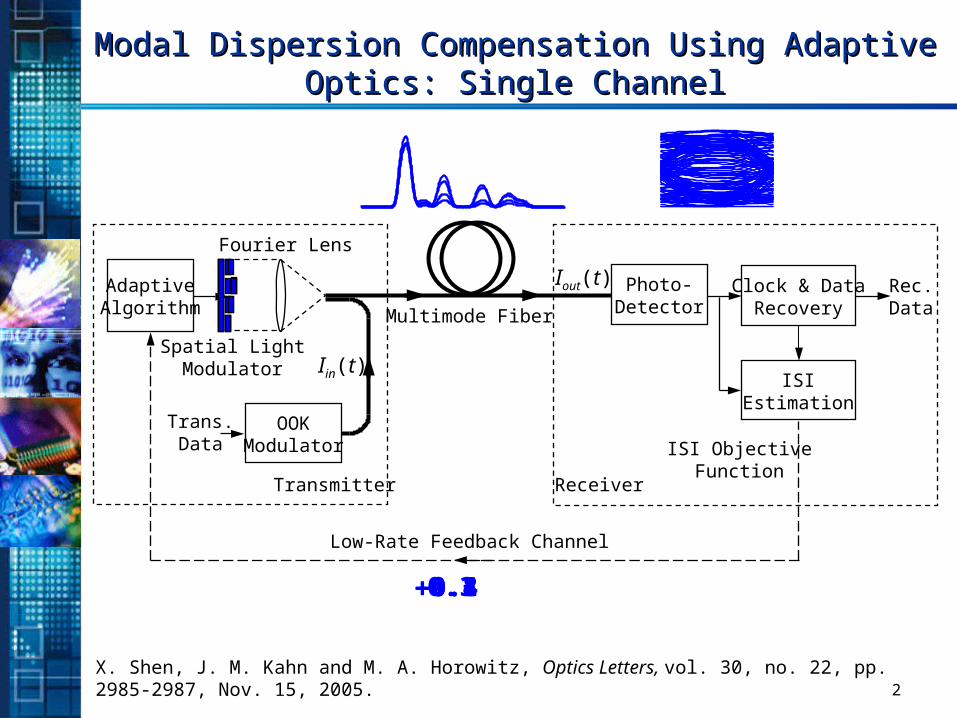
Modal Dispersion Compensation Using Adaptive Modal Dispersion Compensation Using Adaptive Optics: Single ChannelOptics: Single Channel
X. Shen, J. M. Kahn and M. A. Horowitz, Optics Letters, vol. 30, no. 22, pp. 2985-2987, Nov. 15, 2005.
Spatial LightModulator
Multimode Fiber
OOKModulator
AdaptiveAlgorithm
Fourier Lens
Iin(t)
Trans.Data
Transmitter
Low-Rate Feedback Channel
Photo-Detector
Clock & DataRecovery
ISIEstimation
Rec.Data
ISI ObjectiveFunction
Receiver
Iout(t)
0.30.10.40.8
3
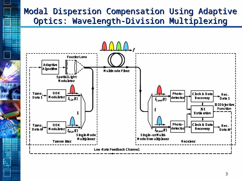
Modal Dispersion Compensation Using Adaptive Modal Dispersion Compensation Using Adaptive Optics: Wavelength-Division MultiplexingOptics: Wavelength-Division Multiplexing
Spatial LightModulator
Multimode Fiber
AdaptiveAlgorithm
Fourier Lens
OOKModulator
Trans.Data 1
Transmitter
Low-Rate Feedback Channel
Photo-detector
Clock & DataRecovery
ISIEstimation
Rec.Data 1
ISI ObjectiveFunction
Receiver
f
OOKModulator
Trans.Data M
…
Single-ModeMultiplexer
I1,in(t)
IM,in(t)Single- or Multi-
Mode Demultiplexer
…
I1,out(t)
IM,out(t)
Photo-detector
Clock & DataRecovery
Rec.Data M
Spatial LightModulator
Multimode Fiber
AdaptiveAlgorithm
Fourier Lens
OOKModulator
Trans.Data 1
Transmitter
Low-Rate Feedback Channel
Photo-detector
Clock & DataRecovery
ISIEstimation
ISIEstimation
Rec.Data 1
ISI ObjectiveFunction
Receiver
ff
OOKModulator
Trans.Data M
…
Single-ModeMultiplexer
I1,in(t)
IM,in(t)Single- or Multi-
Mode Demultiplexer
…
I1,out(t)
IM,out(t)
Photo-detector
Clock & DataRecovery
Clock & DataRecovery
Rec.Data M
4
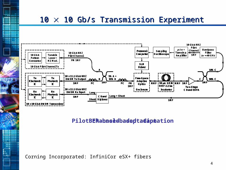
10 10 10 Gb/s Transmission Experiment 10 Gb/s Transmission Experiment
Corning Incorporated: InfiniCor eSX+ fibers
10 10 Gb/s DWDM Transceiver
SMF
10 11.1 Gb/s NRZDWDM Tx Output
SMF
10 11.1 Gb/s NRZDWDM Rx Input
TxElectronic
IC
. . .
TxPhotonic
IC
RxElectronic
IC
RxPhotonic
IC
. . .
C BandDiplexer
Long
Short
Long + Short
PC
A
B5% A +95% B
SMF PMSMF
MMFPC
Free-SpaceAdaptive
Optics
Enclosure
MMF50 m GRINMMF 2.2 km
IncubatorTwo-Stage
C Band EDFA
SMF
C 90% CSMF
10% C
SMF
PersonalComputer
SLMDriver
10 10 Gb/s DWDM Transceiver
SMF
10 11.1 Gb/s NRZDWDM Tx Output
SMF
10 11.1 Gb/s NRZDWDM Rx Input
TxElectronic
IC
TxElectronic
IC
. . .
TxPhotonic
IC
TxPhotonic
IC
RxElectronic
IC
RxElectronic
IC
RxPhotonic
IC
RxPhotonic
IC
. . .
C BandDiplexer
Long
Short
Long + Short
PC
A
B5% A +95% B
SMF PMSMF
MMFPC
Free-SpaceAdaptive
Optics
Enclosure
MMF50 m GRINMMF 2.2 km
IncubatorTwo-Stage
C Band EDFA
SMF
C 90% CSMF
10% C
SMF
PersonalComputerPersonalComputer
SLMDriverSLM
Driver
BER-based adaptation
10 10 Gb/s DWDM Transceiver
SMF
10 11.1 Gb/s NRZDWDM Tx Output
SMF
10 11.1 Gb/s NRZDWDM Rx Input
TxElectronic
IC
. . .
TxPhotonic
IC
RxElectronic
IC
RxPhotonic
IC
. . .
C BandDiplexer
Long
Short
Long + Short
PC
10 Gb/s Pilot Channel Tx
10 Gb/sPattern
Generator
Tunable Laser +MZ Mod. PM SMF
10 Gb/s NRZPilot Channel
A
B5% A +95% B
SMF PMSMF
MMFPC
Free-SpaceAdaptive
Optics
Enclosure
MMF50 m GRINMMF 2.2 km
IncubatorTwo-Stage
C Band EDFA
SMF
C 90% CSMF
10% C
SMF
BandpassFilter
40 GHz
p-i-n +Transimp.Amplifier
PersonalComputer
SLMDriver
SamplingOscilloscope
10 Gb/s NRZPilot
Channel
SMF
10 10 Gb/s DWDM Transceiver
SMF
10 11.1 Gb/s NRZDWDM Tx Output
SMF
10 11.1 Gb/s NRZDWDM Rx Input
TxElectronic
IC
TxElectronic
IC
. . .
TxPhotonic
IC
TxPhotonic
IC
RxElectronic
IC
RxElectronic
IC
RxPhotonic
IC
RxPhotonic
IC
. . .
C BandDiplexer
Long
Short
Long + Short
PC
10 Gb/s Pilot Channel Tx
10 Gb/sPattern
Generator
Tunable Laser +MZ Mod. PM SMF
10 Gb/s NRZPilot Channel
A
B5% A +95% B
SMF PMSMF
MMFPC
Free-SpaceAdaptive
Optics
Enclosure
MMF50 m GRINMMF 2.2 km
IncubatorTwo-Stage
C Band EDFA
SMF
C 90% CSMF
10% C
SMF
BandpassFilter
40 GHz
p-i-n +Transimp.Amplifier
PersonalComputerPersonalComputer
SLMDriverSLM
Driver
SamplingOscilloscope
SamplingOscilloscope
10 Gb/s NRZPilot
Channel
SMF
Pilot channel-based adaptation
5
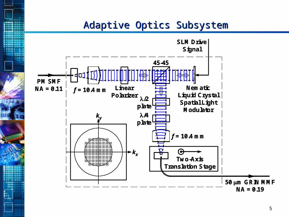
Adaptive Optics SubsystemAdaptive Optics Subsystem
PM SMFNA = 0.11 f = 10.4 mm
f = 10.4 mm
50 m GRIN MMFNA = 0.19
45-45
Linear Polarizer
NematicLiquid Crystal Spatial Light
Modulator
/2plate
/4plate
Enclosure
SLM DriveSignal
Two-AxisTranslation Stage
PM SMFNA = 0.11 f = 10.4 mm
f = 10.4 mm
50 m GRIN MMFNA = 0.19
45-45
Linear Polarizer
NematicLiquid Crystal Spatial Light
Modulator
/2plate
/4plate
Enclosure
SLM DriveSignal
Two-AxisTranslation Stage
kx
ky
kx
ky
6
Po
we
r in
0.2
nm
BW
(d
Bm
)
Wavelength (nm)
5
10
15
20
25
1545 1549 1553 1557 1561 1565
Po
we
r in
0.2
nm
BW
(d
Bm
)
Wavelength (nm)
5
10
15
20
25
1545 1549 1553 1557 1561 1565
Po
we
r in
0.2
nm
BW
(d
Bm
)
Wavelength (nm)
5
10
15
20
25
1545 1549 1553 1557 1561 15650 1 2 3 4 5 6 7 8 9 10
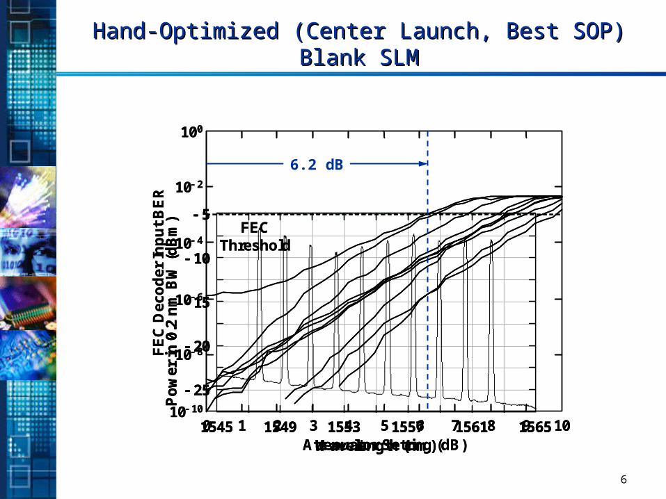
FE
C D
eco
der
In
pu
t B
ER
Attenuator Setting (dB)
100
10 2
10 4
10 6
10 8
10 10
FECThreshold
0 1 2 3 4 5 6 7 8 9 10
FE
C D
eco
der
In
pu
t B
ER
Attenuator Setting (dB)
100
10 2
10 4
10 6
10 8
10 10
FECThreshold
Hand-Optimized (Center Launch, Best SOP)Hand-Optimized (Center Launch, Best SOP)Blank SLMBlank SLM
6.2 dB
7
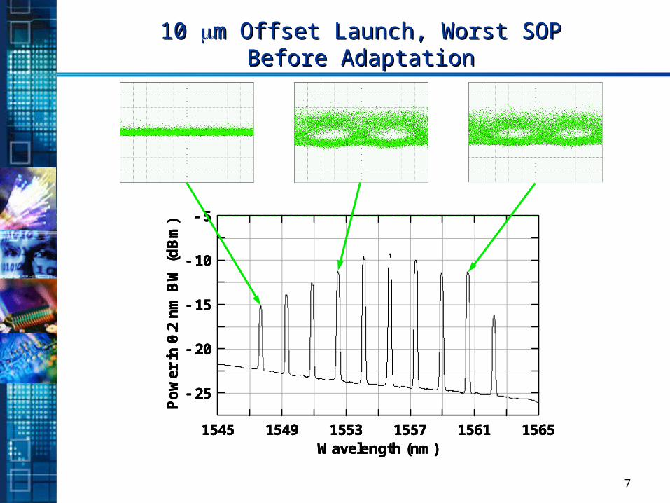
10 10 m Offset Launch, Worst SOPm Offset Launch, Worst SOPBefore AdaptationBefore Adaptation
Po
we
r in
0.2
nm
BW
(d
Bm
)
Wavelength (nm)
5
10
15
20
25
1545 1549 1553 1557 1561 1565
Po
we
r in
0.2
nm
BW
(d
Bm
)
Wavelength (nm)
5
10
15
20
25
1545 1549 1553 1557 1561 1565
Po
we
r in
0.2
nm
BW
(d
Bm
)
Wavelength (nm)
5
10
15
20
25
1545 1549 1553 1557 1561 1565
8
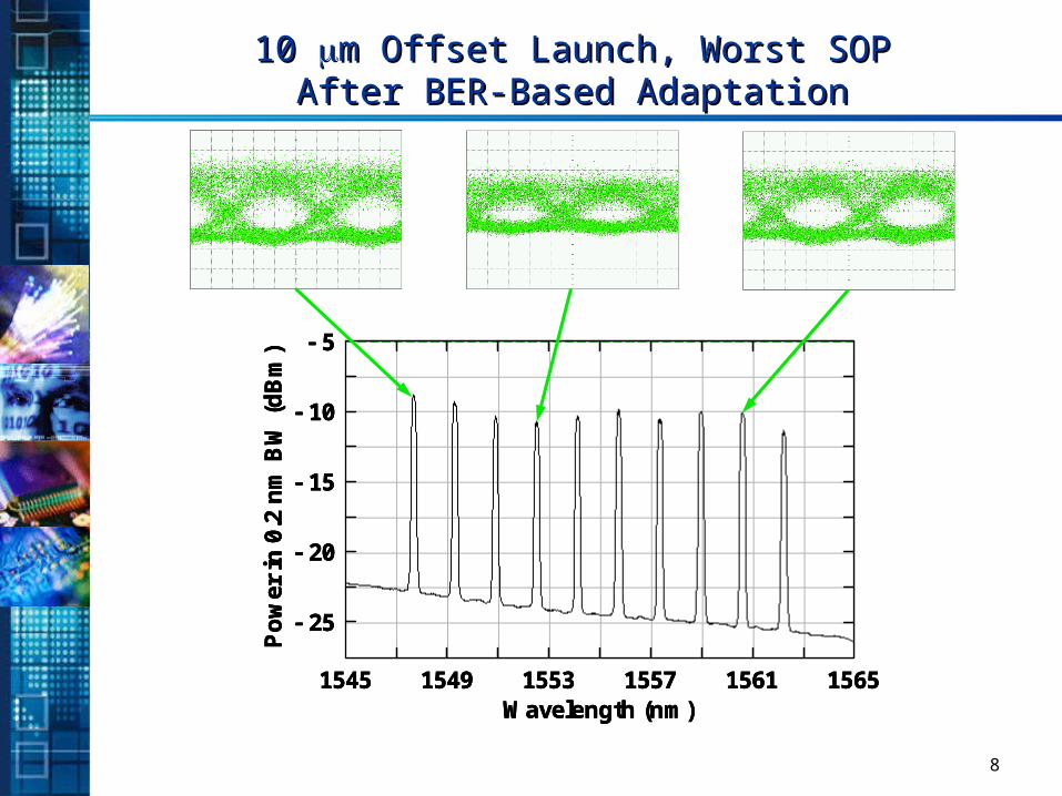
10 10 m Offset Launch, Worst SOPm Offset Launch, Worst SOPAfter BER-Based AdaptationAfter BER-Based Adaptation
Po
wer
in 0
.2 n
m B
W (
dB
m)
Wavelength (nm)
5
10
15
20
25
1545 1549 1553 1557 1561 1565
Po
wer
in 0
.2 n
m B
W (
dB
m)
Wavelength (nm)
5
10
15
20
25
1545 1549 1553 1557 1561 1565
Po
wer
in 0
.2 n
m B
W (
dB
m)
Wavelength (nm)
5
10
15
20
25
1545 1549 1553 1557 1561 1565
9
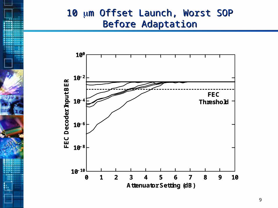
10 10 m Offset Launch, Worst SOPm Offset Launch, Worst SOPBefore AdaptationBefore Adaptation
0 1 2 3 4 5 6 7 8 9 10
FE
C D
eco
der
In
pu
t B
ER
Attenuator Setting (dB)
100
10 2
10 4
10 6
10 8
10 10
FECThreshold
0 1 2 3 4 5 6 7 8 9 10
FE
C D
eco
der
In
pu
t B
ER
Attenuator Setting (dB)
100
10 2
10 4
10 6
10 8
10 10
FECThreshold
10
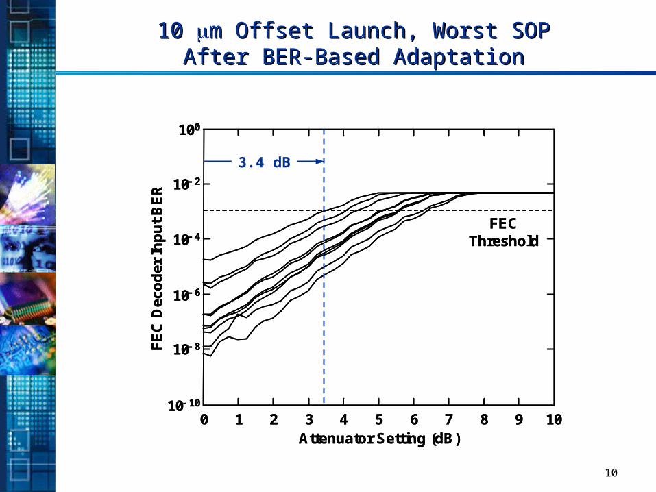
10 10 m Offset Launch, Worst SOPm Offset Launch, Worst SOPAfter BER-Based AdaptationAfter BER-Based Adaptation
0 1 2 3 4 5 6 7 8 9 10
FE
C D
eco
der
In
pu
t B
ER
Attenuator Setting (dB)
100
10 2
10 4
10 6
10 8
10 10
FECThreshold
0 1 2 3 4 5 6 7 8 9 10
FE
C D
eco
der
In
pu
t B
ER
Attenuator Setting (dB)
100
10 2
10 4
10 6
10 8
10 10
FECThreshold
3.4 dB
11
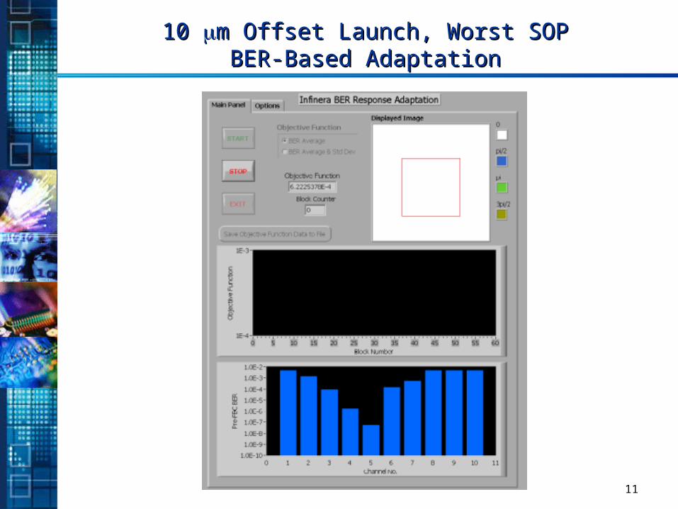
10 10 m Offset Launch, Worst SOPm Offset Launch, Worst SOPBER-Based AdaptationBER-Based Adaptation
Recommended