Innovative Fluid Power
Proper Pump Installation Practices
80-779, Rev. 10/08
Innovative Fluid Power
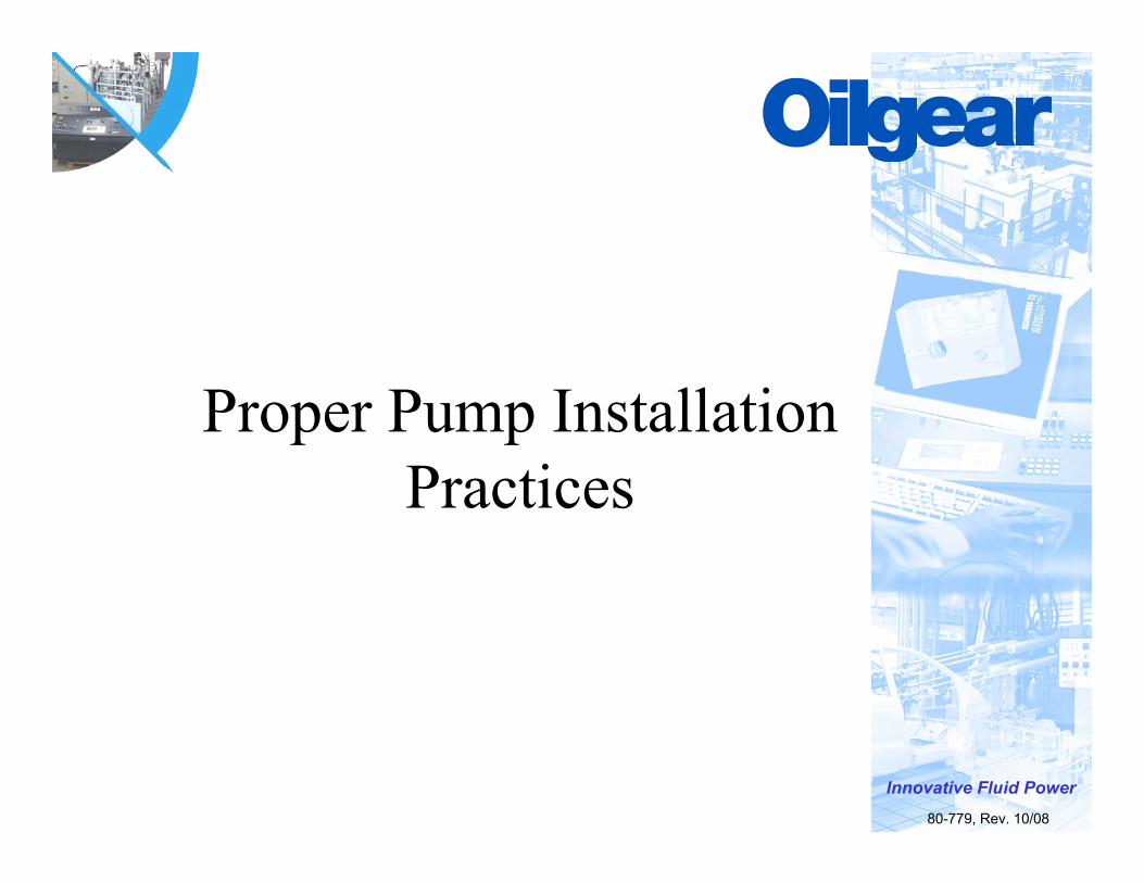
There is a Reason Every Unit Comes With This Bright
Orange Tag !

Innovative Fluid Power
Proper Alignment and Coupling Installation
• Do Not Drive Coupling Onto Shaft• Pump Alignment Must be .005” TIR• Make Sure Coupling Halves are Not Touching
*Can Induce Thrust load and Misalignment• Use Keyed Shaft for Industrial Applications
*Oilgear Standard Splines are Designed to be Loose*Do Not Use Split Spline Couplings
Innovative Fluid Power
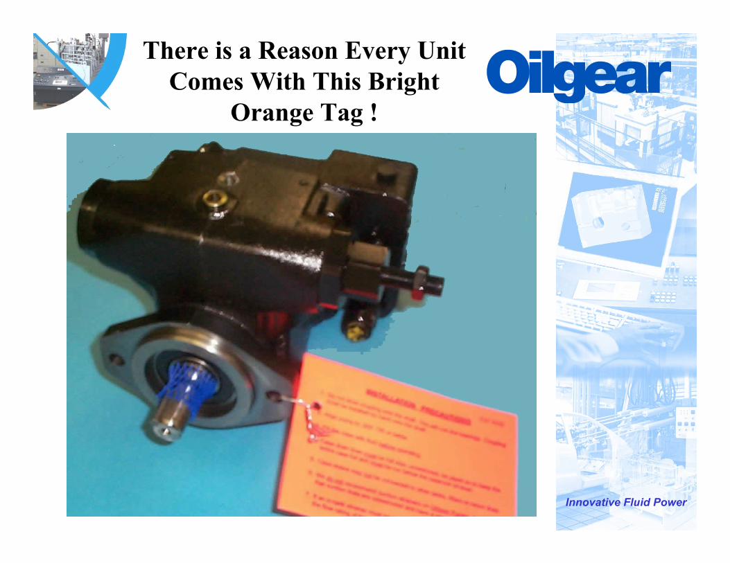
Bearings are Designed to Carry Side Loads Not Thrust Loads
Side Load
Thrust Load
Driving on a coupling or coupling halves touching -Creates a thrust load, damaging balls and race’s of front bearing.
Innovative Fluid Power
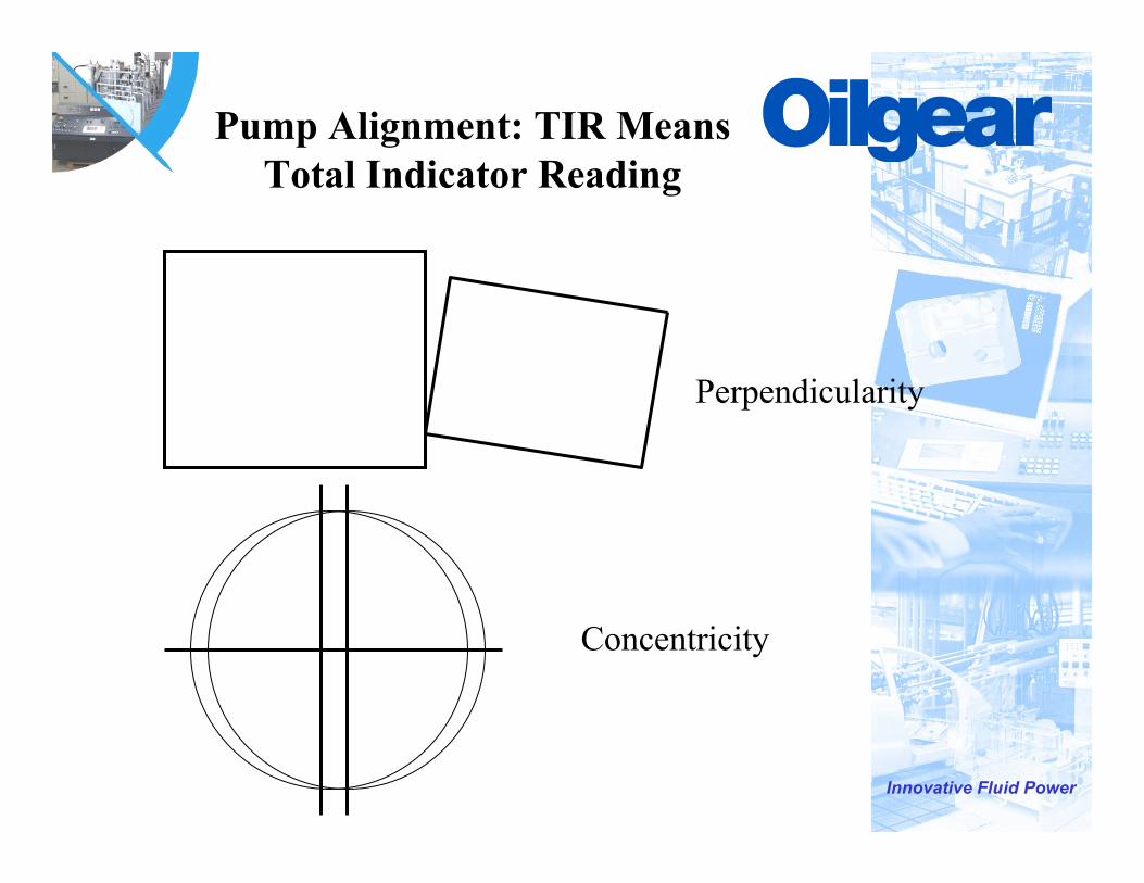
Pump Alignment: TIR Means Total Indicator Reading
Perpendicularity
Concentricity

Innovative Fluid Power
Effect of Misalignment
Side Load
Cylinder Not Parallel with Valve Plate
Innovative Fluid Power
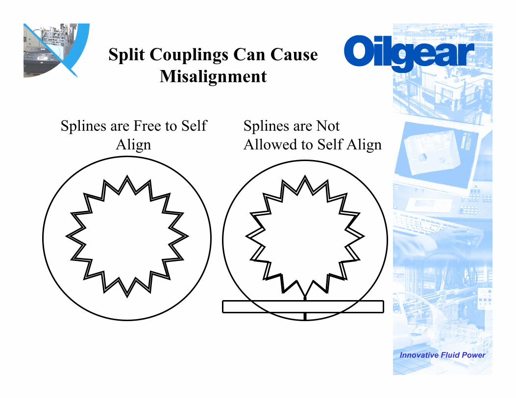
Split Couplings Can Cause Misalignment
Splines are Free to Self Align
Splines are Not Allowed to Self Align

Innovative Fluid Power
Case Drain Lines
• Lines Must be Full Size• Lines Must be Unrestricted• Lines May Not be Connected to Other Return
Lines• Lines May Not be Connected to Filters, Coolers• Lines Must be Plumbed so that Case Remains Full
at All Times • Lines Must be Terminated Below Oil Level
Innovative Fluid Power
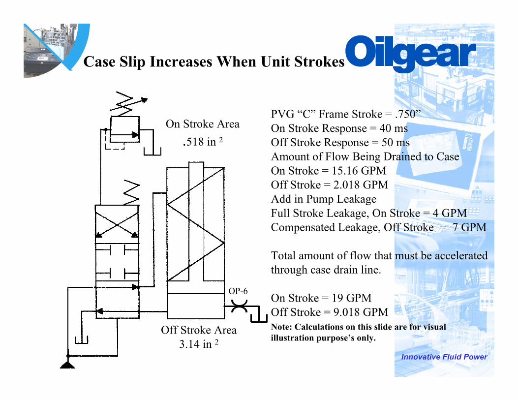
Case Slip Increases When Unit Strokes
Off Stroke Area3.14 in 2
On Stroke Area.518 in 2
PVG “C” Frame Stroke = .750”On Stroke Response = 40 msOff Stroke Response = 50 msAmount of Flow Being Drained to CaseOn Stroke = 15.16 GPMOff Stroke = 2.018 GPMAdd in Pump LeakageFull Stroke Leakage, On Stroke = 4 GPMCompensated Leakage, Off Stroke = 7 GPM
Total amount of flow that must be accelerated through case drain line.
On Stroke = 19 GPMOff Stroke = 9.018 GPMNote: Calculations on this slide are for visual illustration purpose’s only.
OP-6
Innovative Fluid Power
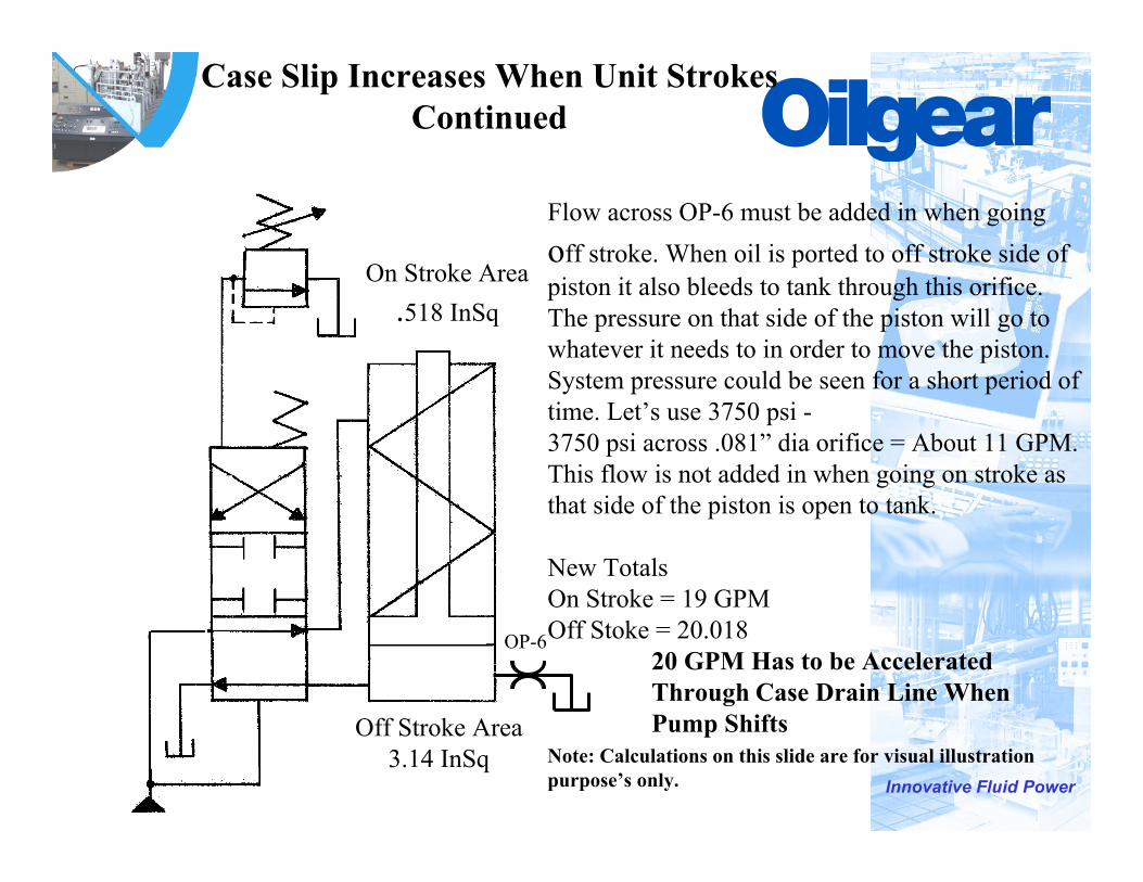
Case Slip Increases When Unit StrokesContinued
Off Stroke Area3.14 InSq
On Stroke Area.518 InSq
OP-6
Flow across OP-6 must be added in when goingoff stroke. When oil is ported to off stroke side of piston it also bleeds to tank through this orifice. The pressure on that side of the piston will go to whatever it needs to in order to move the piston. System pressure could be seen for a short period of time. Let’s use 3750 psi -3750 psi across .081” dia orifice = About 11 GPM. This flow is not added in when going on stroke as that side of the piston is open to tank.
New TotalsOn Stroke = 19 GPMOff Stoke = 20.018
20 GPM Has to be Accelerated Through Case Drain Line When Pump Shifts
Note: Calculations on this slide are for visual illustration purpose’s only.
Innovative Fluid Power
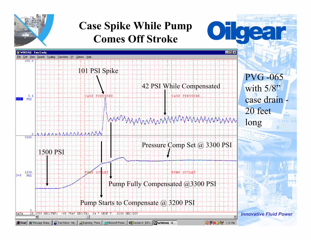
Case Spike While Pump Comes Off Stroke
Pressure Comp Set @ 3300 PSI1500 PSI
Pump Starts to Compensate @ 3200 PSI
Pump Fully Compensated @3300 PSI
101 PSI Spike
42 PSI While CompensatedPVG -065 with 5/8”case drain -20 feet long
Innovative Fluid Power
Effects of Case Pressure
• Shaft Seal Failure*Standard Seal Rated to 25 PSI
• Gasket Failures• Piston Shoe Swashblock Failure
*Shoe Lift
Innovative Fluid Power
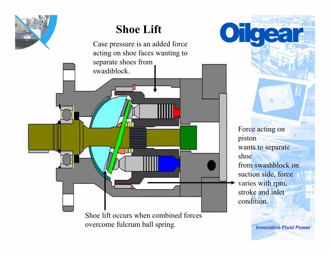
Shoe Lift
Force acting on pistonwants to separate shoefrom swashblock on suction side, force varies with rpm, stroke and inlet condition.
Case pressure is an added force acting on shoe faces wanting to separate shoes from swashblock.
Shoe lift occurs when combined forces overcome fulcrum ball spring.
Innovative Fluid Power
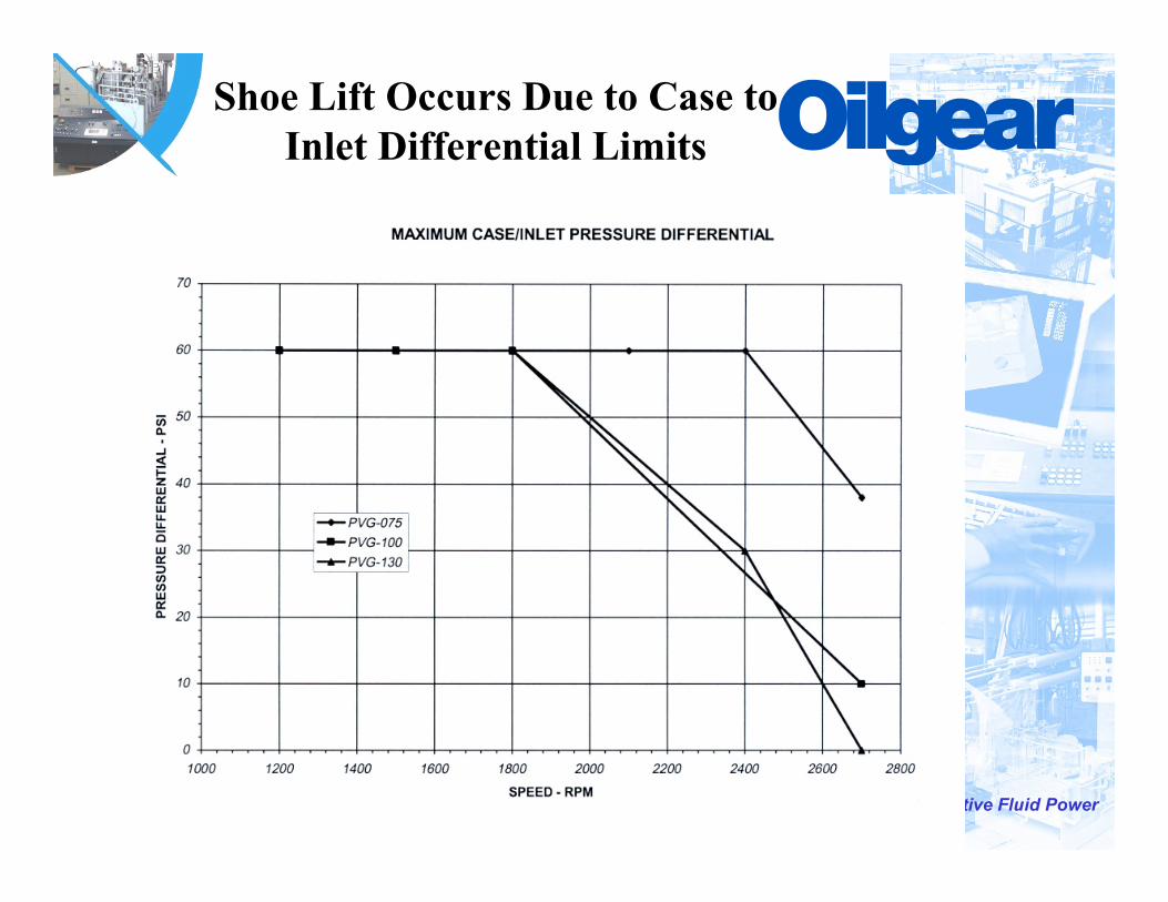
Shoe Lift Occurs Due to Case to Inlet Differential Limits
Innovative Fluid Power
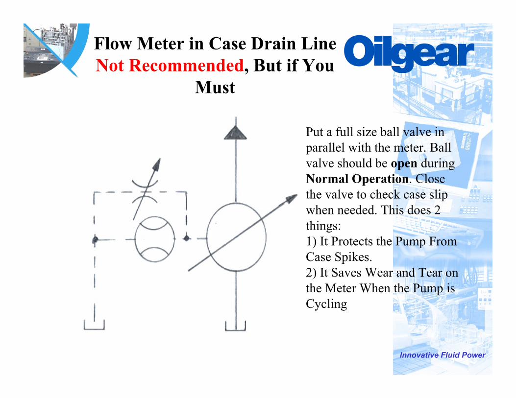
Flow Meter in Case Drain Line Not Recommended, But if You
Must
Put a full size ball valve in parallel with the meter. Ball valve should be open during Normal Operation. Close the valve to check case slip when needed. This does 2 things:1) It Protects the Pump From Case Spikes.2) It Saves Wear and Tear on the Meter When the Pump is Cycling
Innovative Fluid Power
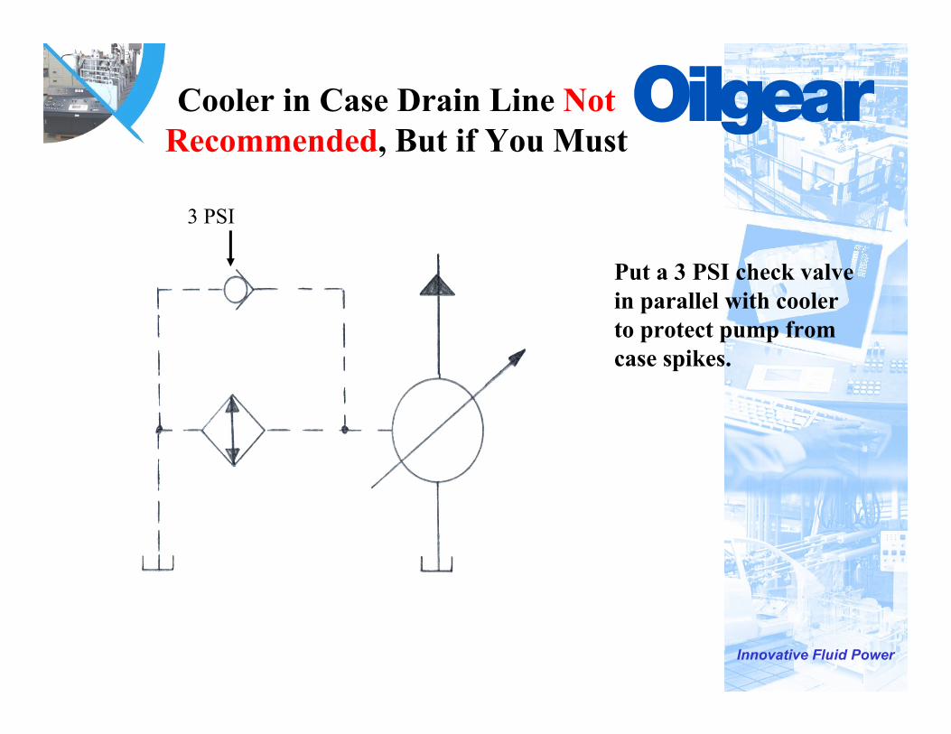
Cooler in Case Drain Line Not Recommended, But if You Must
Put a 3 PSI check valve in parallel with cooler to protect pump from case spikes.
3 PSI
Innovative Fluid Power
Inlet Conditions
• Inlet Lines Should be Full Size• Inlet Lines Should be Unrestricted and as Short
as Possible• Inlet Lines Should Have a Minimum of Fittings
and Elbows• Inlet Location
*Away From Return Lines*Proper Reservoir Baffling
• Suction Strainers are Not Recommended*If Required Size for 3 Times Pump
Volume
Innovative Fluid Power
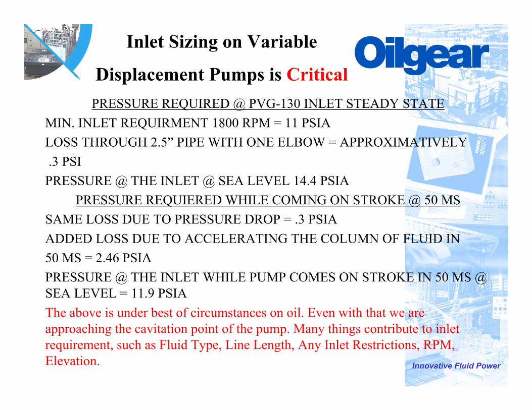
Inlet Sizing on Variable
Displacement Pumps is CriticalPRESSURE REQUIRED @ PVG-130 INLET STEADY STATE
MIN. INLET REQUIRMENT 1800 RPM = 11 PSIA LOSS THROUGH 2.5” PIPE WITH ONE ELBOW = APPROXIMATIVELY.3 PSIPRESSURE @ THE INLET @ SEA LEVEL 14.4 PSIA
PRESSURE REQUIERED WHILE COMING ON STROKE @ 50 MSSAME LOSS DUE TO PRESSURE DROP = .3 PSIAADDED LOSS DUE TO ACCELERATING THE COLUMN OF FLUID IN50 MS = 2.46 PSIAPRESSURE @ THE INLET WHILE PUMP COMES ON STROKE IN 50 MS @ SEA LEVEL = 11.9 PSIAThe above is under best of circumstances on oil. Even with that we are approaching the cavitation point of the pump. Many things contribute to inlet requirement, such as Fluid Type, Line Length, Any Inlet Restrictions, RPM, Elevation.
Innovative Fluid Power
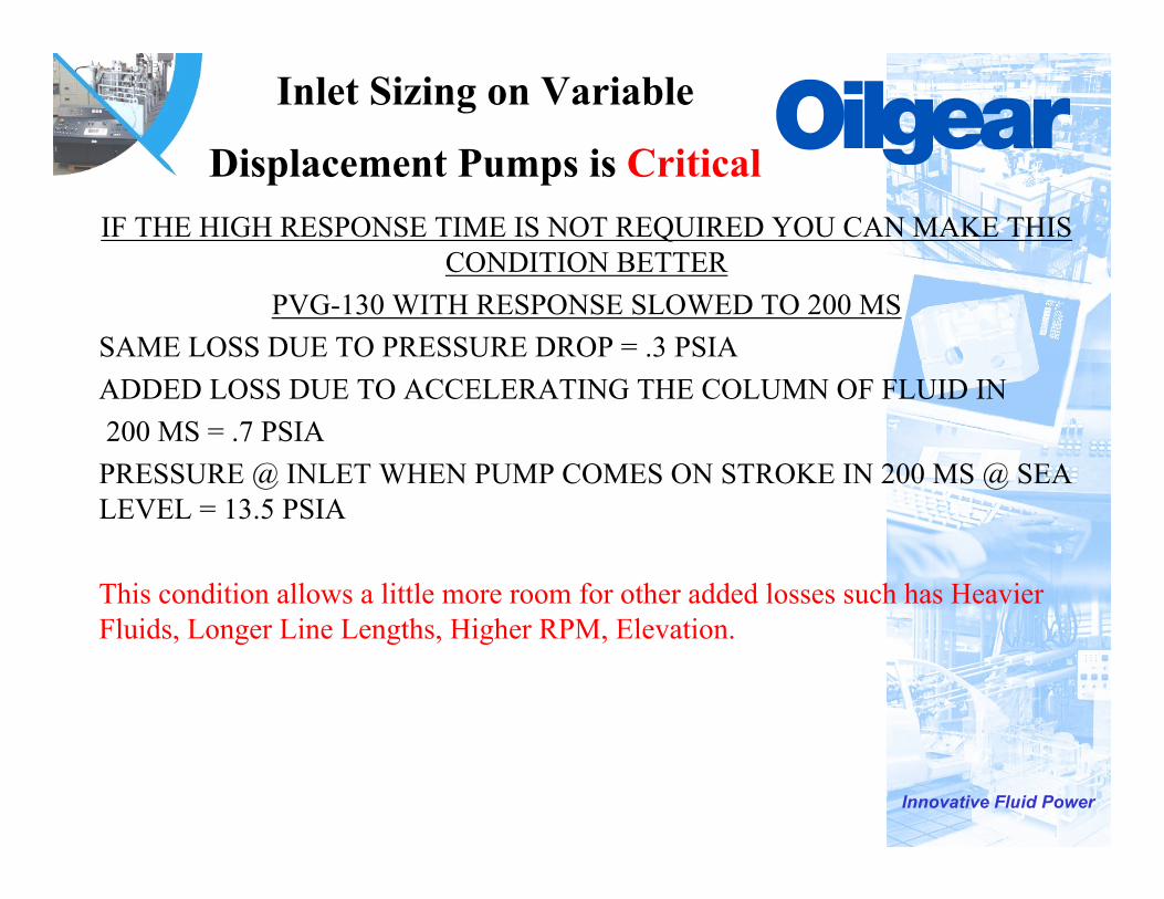
Inlet Sizing on Variable
Displacement Pumps is CriticalIF THE HIGH RESPONSE TIME IS NOT REQUIRED YOU CAN MAKE THIS
CONDITION BETTERPVG-130 WITH RESPONSE SLOWED TO 200 MS
SAME LOSS DUE TO PRESSURE DROP = .3 PSIAADDED LOSS DUE TO ACCELERATING THE COLUMN OF FLUID IN200 MS = .7 PSIAPRESSURE @ INLET WHEN PUMP COMES ON STROKE IN 200 MS @ SEA LEVEL = 13.5 PSIA
This condition allows a little more room for other added losses such has Heavier Fluids, Longer Line Lengths, Higher RPM, Elevation.
Innovative Fluid Power
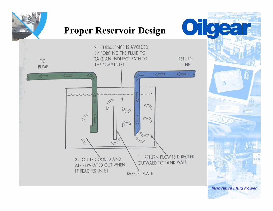
Proper Reservoir Design

Innovative Fluid Power
Be Aware of Pump Inlet Characteristics

Innovative Fluid Power
Fast Acting Relief
• Fast Acting Relief Always Recommended
• Pressure Compensators Not Meant to Act as System Relief
*Flow is Still Being Delivered to the System While Pump is Coming Off Stroke
• Relief Should be Set 300 PSI Above Compensator Setting
Innovative Fluid Power
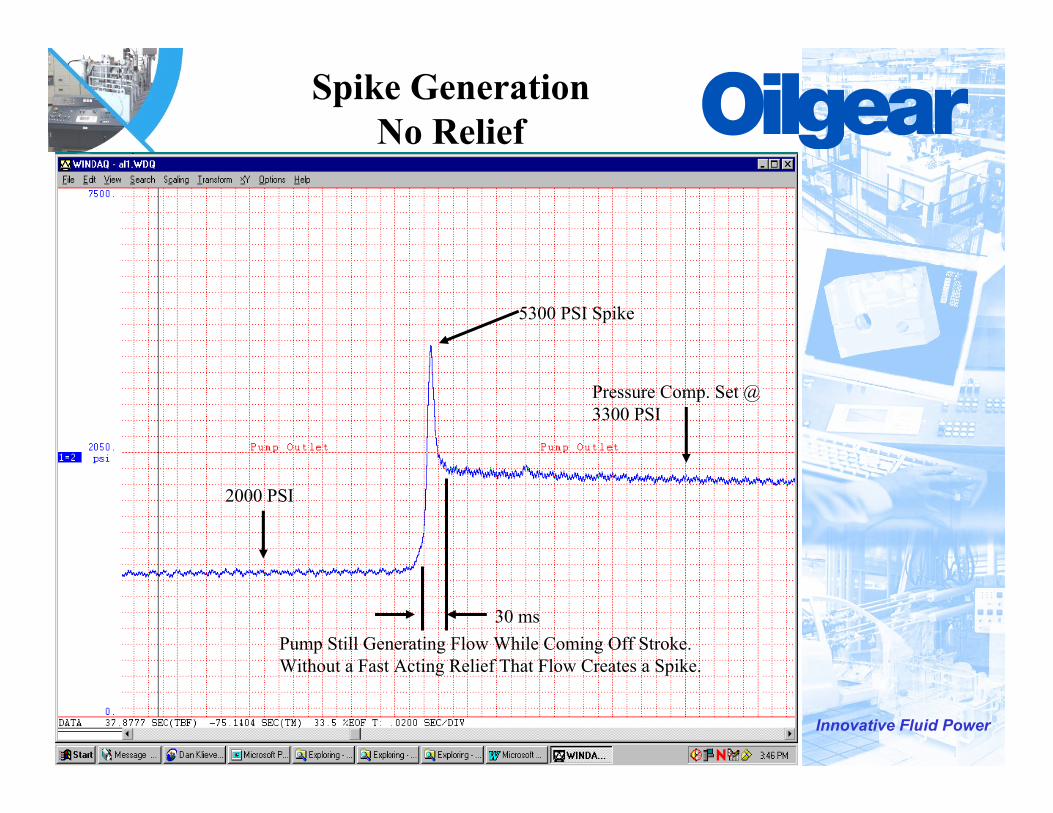
Spike GenerationNo Relief
Pressure Comp. Set @ 3300 PSI
5300 PSI Spike
2000 PSI
30 msPump Still Generating Flow While Coming Off Stroke.Without a Fast Acting Relief That Flow Creates a Spike.
Innovative Fluid Power
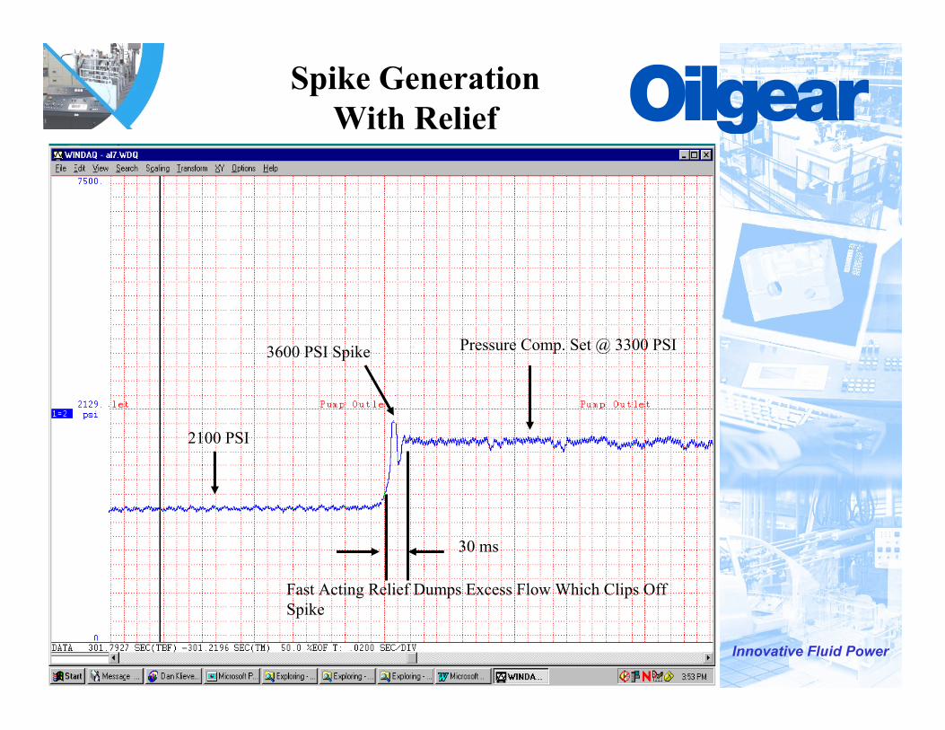
Spike GenerationWith Relief
Pressure Comp. Set @ 3300 PSI3600 PSI Spike
30 ms
2100 PSI
Fast Acting Relief Dumps Excess Flow Which Clips Off Spike
Innovative Fluid Power
Filtration
• Use Minimum 10 Micron Filters• Use By-Pass Filters With Indicators• Off Line Filtration Preferred• Keep Fluid to Recommended ISO Level
Innovative Fluid Power
Start Up
• Make Sure Tank is Full of Fluid• Make Sure All Shut off Valves are Open• Fill Case Completely Before Operating• Check for Proper Rotation
*Rotation is Referenced Looking at Pump Shaft
• Provide a Means of Purging Air From Discharge Line
• Back Out Pressure Compensator and System Relief
• Jog Motor if Possible

Innovative Fluid Power
• Following the proper installation procedure directly relates to the success of the application and the life of the pump.
Thank-You
Recommended