1
1
Ji Zhong (季忠) Ph.D., Professor
Packaging Research Institute
Phone: 0531-88392817
Email: [email protected]
Http://www.dplab.sdu.edu.cn
Office: RM908, Main Building (Qianfoshan Campus);
RM510, Xipeilou
2/43
Plastic in Packaging
Lesson 4 c
3/43
Plastic and polymer are often used interchangeably
Smallest repetitive unit in a polymer
Monomer units are joined together to make a a larger polymer molecule
But plastic tends to be used to describe finished partspolymer tends to describe raw materials
Polymers can be grouped into two classes:Thermoplastic and thermoset or commodity and engineering polymers
日用品
Plastics: 1. plastic +s 信用卡,塑料件2. plastics 塑料 整形外科
Derived from petrochemicals
Polymer and Plastic
4/43
1. What elements are in the molecule? (C, H, Cl chlorine)a water molecule has only three atoms
a typical molecule contains hundreds or thousands of atoms
2. What size (molecular weight) is the molecule?• Today there are hundred of identified(识别,认明)species
|| ‘spɪːʃɪːz 种类of synthetic 合成的 polymer.• Any polymer is available in a range of molecular masses, most can
be modified by the addition of other monomers.• In reality, the choice in plastics is almost limitless.• Properties such as melting point, stiffness will change as
molecular weight changes
Polymer Properties Depend On:
[ˈklɔrin]
2
5/43
3. Is the molecule polar or non-polar?It’s depending on the participating参与 含有 atoms [,sɔlju'biliti]
Often influence melting point , COF, solubility 溶性, barrier properties
4. What shape is the molecule?
It will determine how large numbers of them will fit together
Many physical properties are affected by the molecule’s shape
5. What is its thermal history?
Final property depends on it. Changing it changes the plastic’s
performance characteristics
Polymer Properties Depend On:
6/43
6. What is its mechanical history?
A plastic’s final properties also depend on its mechanical history, how it flowed in the molten state and how it was stressed when
cold.
Polymer Properties Depend On:
7/43
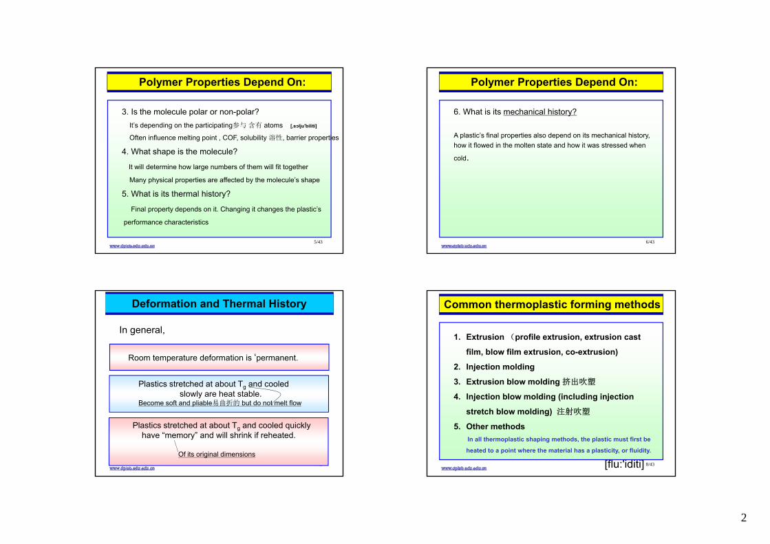
Deformation and Thermal History
Room temperature deformation is ‘permanent.
Plastics stretched at about Tg and cooled slowly are heat stable.
Become soft and pliable易曲折的 but do not melt flow
Plastics stretched at about Tg and cooled quicklyhave “memory” and will shrink if reheated.
Of its original dimensions
In general,
8/43
1. Extrusion (profile extrusion, extrusion cast
film, blow film extrusion, co-extrusion)
2. Injection molding
3. Extrusion blow molding 挤出吹塑
4. Injection blow molding (including injection
stretch blow molding) 注射吹塑
5. Other methodsIn all thermoplastic shaping methods, the plastic must first be
heated to a point where the material has a plasticity, or fluidity.
Common thermoplastic forming methods
[flu:'iditi]
3
9/43
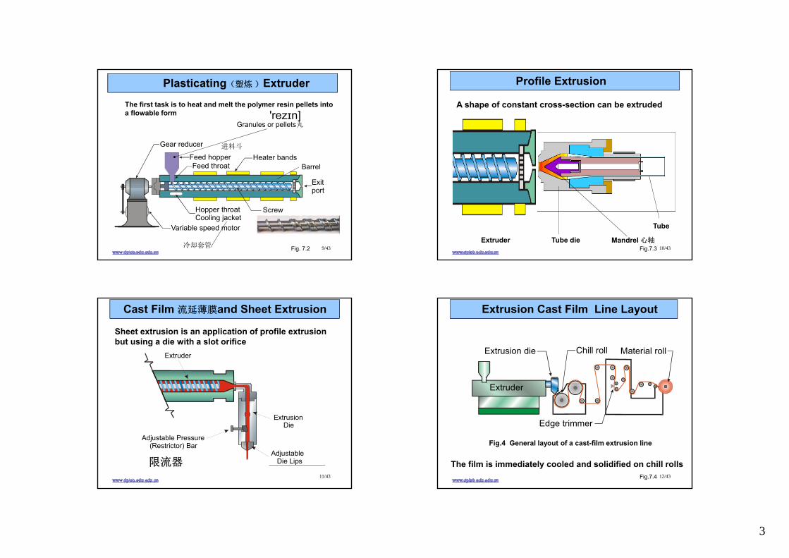
Plasticating(塑炼 )Extruder
Exitport
Gear reducer
Variable speed motor
Feed throatFeed hopper
Hopper throatCooling jacket
Screw
Heater bands
Fig. 7.2
Granules or pellets丸
进料斗
冷却套管
Barrel
The first task is to heat and melt the polymer resin pellets into a flowable form 'rezɪn]
10/43Fig.7.3Extruder Tube die Mandrel 心轴
Tube
Profile Extrusion
A shape of constant cross-section can be extruded
11/43
Adjustable Die Lips
Extrusion Die
Adjustable Pressure (Restrictor) Bar
Extruder
Cast Film 流延薄膜and Sheet Extrusion
限流器
Sheet extrusion is an application of profile extrusion but using a die with a slot orifice
12/43
Extrusion Cast Film Line Layout
Extruder
Extrusion die Chill roll
Edge trimmer
Material roll
Fig.7.4
The film is immediately cooled and solidified on chill rolls
Fig.4 General layout of a cast-film extrusion line
4
13/43
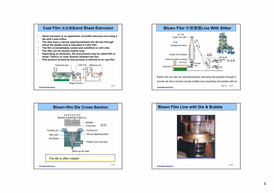
Cast Film 流延薄膜and Sheet Extrusion
• Sheet extrusion is an application of profile extrusion but using a die with a slot orifice
• The dies have a narrow opening between the die lips through which the plastic melt is extruded in a thin film
• The film is immediately cooled and solidified on chill rolls• The dies can be several metres long • Depending on thickness, the end product may be called film or
sheet. There’s no clear division between the two• Film product formed by this process is referred to as cast film
Extruder
Extrusion die Chill roll
Edge trimmer
Material roll
14/43
ExtruderCircular die
Air ringInternal bubble cooling
Plastic film bubble
Collapsing frame
Upper nip rolls
SlitterDual rollwinder
Blown Film 吹塑薄膜Line With Slitter
Fig.7.5
Plastic film can also be manufactured by extruding the polymer through a
circular die into a closed circular bubble and expanding the bubble with air
展平辊
复卷机
收缩
纵切机
15/43
Bubble
Blow-up air inlet
Cooling air Cooling air
Plastic from extruder
Die lip adjusting bolts
Die BodyDie core
Frost line
Bubble constantly pulled up
Blown-film Die Cross-Section
The die is often rotated
霜线
16/43
Blown Film Line with Die & Bubble
5
17/43
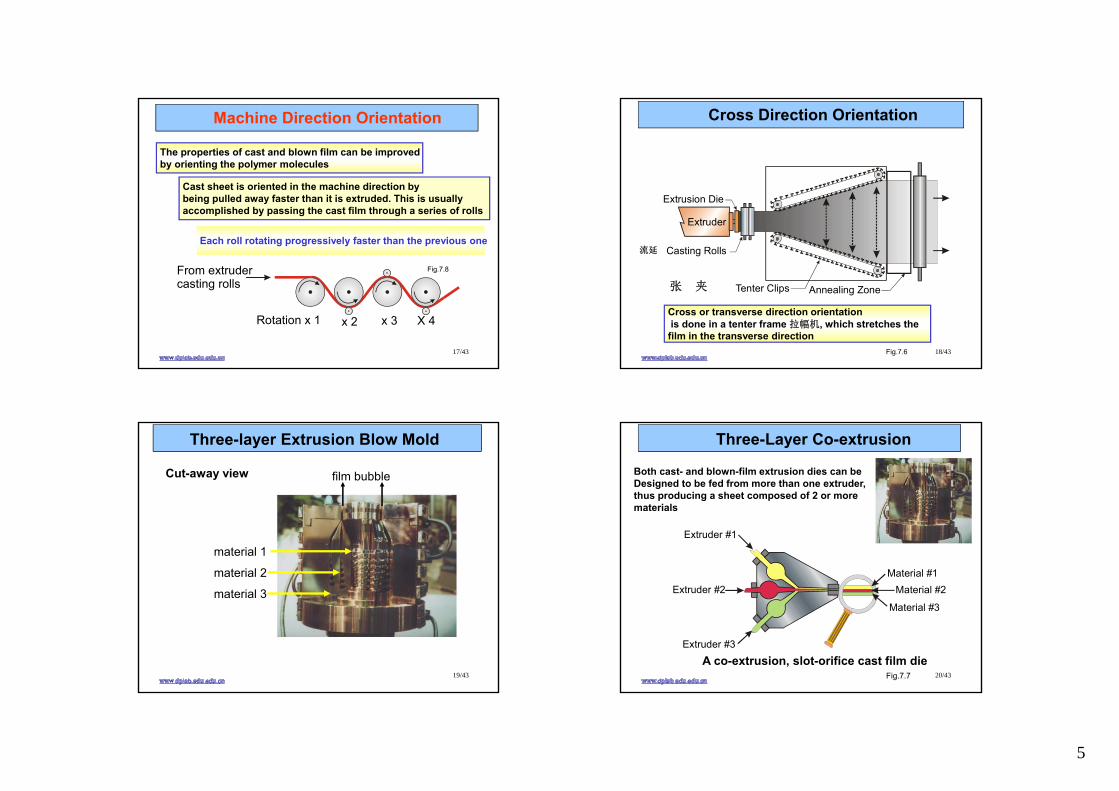
Machine Direction Orientation
Rotation x 1 x 3x 2 X 4
From extruder casting rolls
Fig.7.8
The properties of cast and blown film can be improved by orienting the polymer molecules
Cast sheet is oriented in the machine direction by being pulled away faster than it is extruded. This is usually accomplished by passing the cast film through a series of rolls
Each roll rotating progressively faster than the previous one
18/43
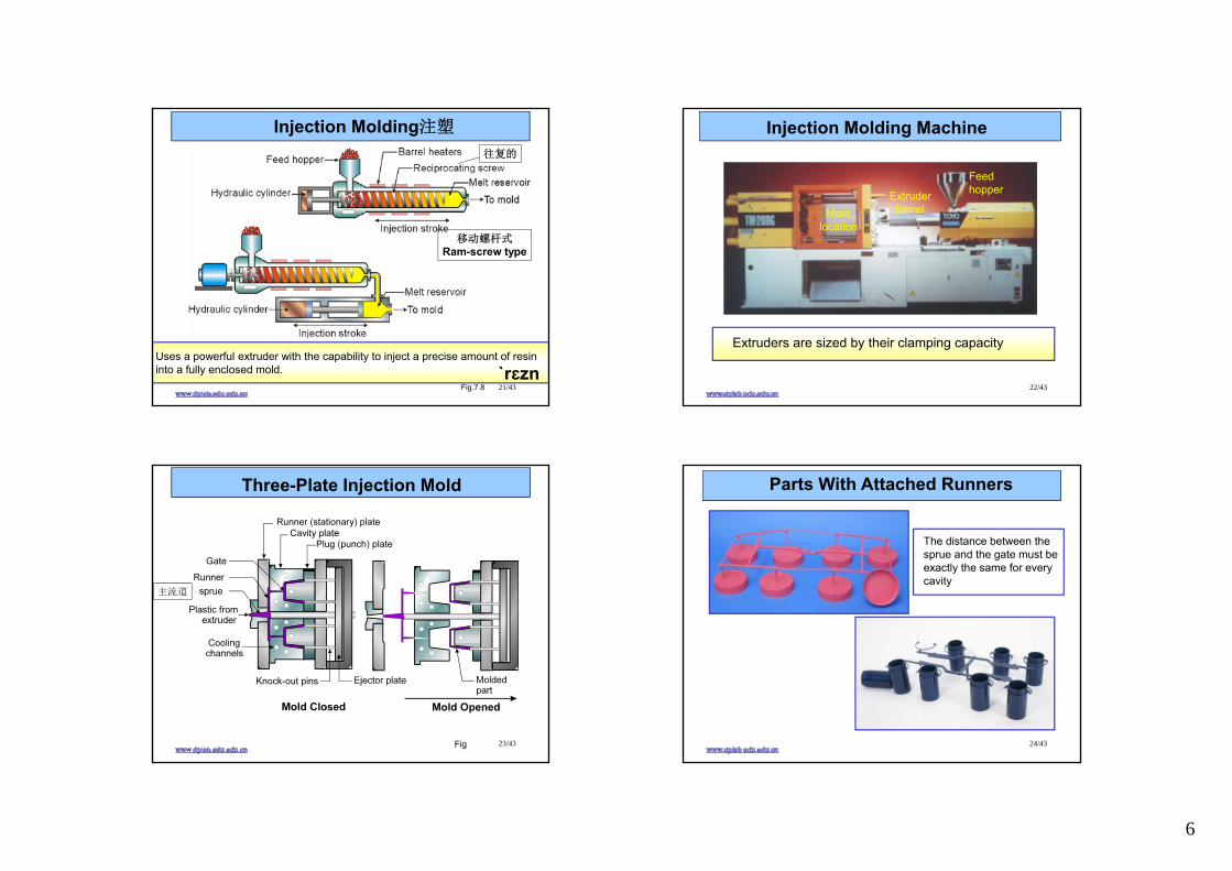
Extruder
Casting Rolls
Annealing Zone
Extrusion Die
Tenter Clips
Cross Direction Orientation
Fig.7.6
Cross or transverse direction orientationis done in a tenter frame 拉幅机, which stretches the film in the transverse direction
张 夹
流延
19/43
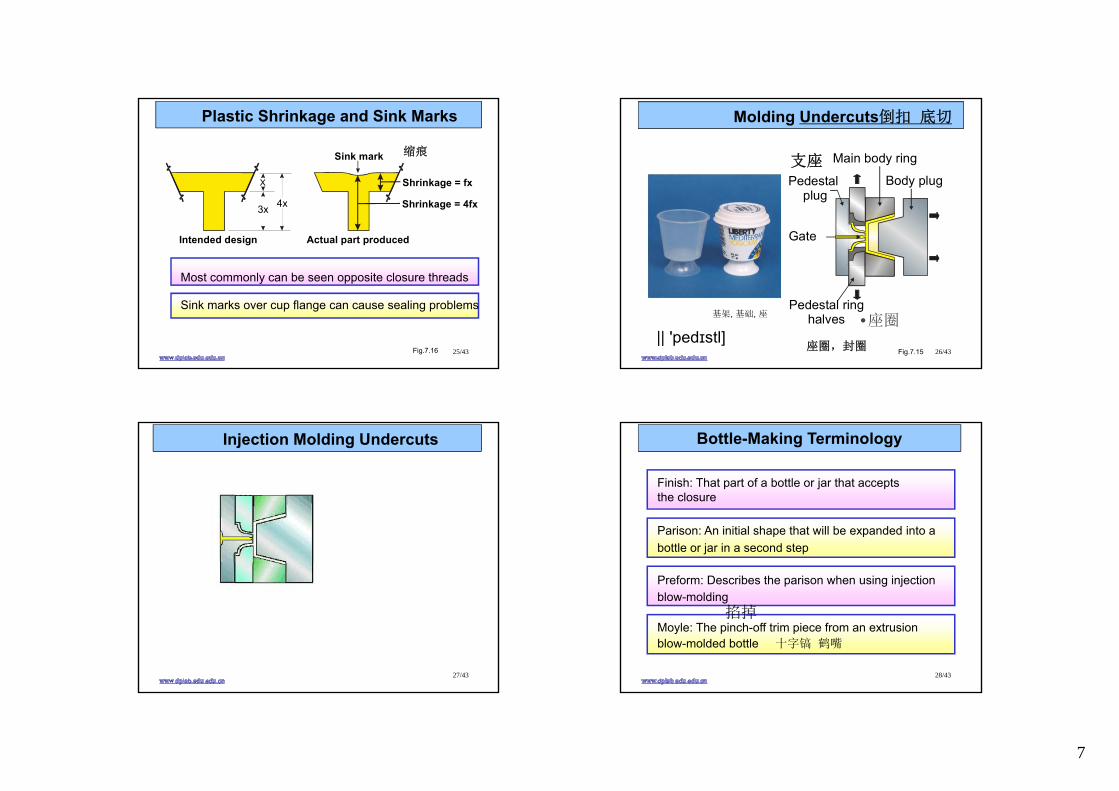
Three-layer Extrusion Blow Mold
Cut-away view
material 1
material 2
material 3
film bubble
20/43
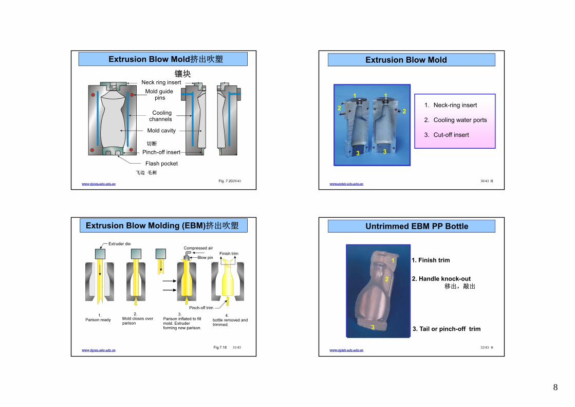
Extruder #1
Extruder #2
Extruder #3
Material #1Material #2
Material #3
Three-Layer Co-extrusion
Fig.7.7
Both cast- and blown-film extrusion dies can be Designed to be fed from more than one extruder,thus producing a sheet composed of 2 or morematerials
A co-extrusion, slot-orifice cast film die
6
21/43
Injection Molding注塑
Fig.7.8
往复的
Uses a powerful extruder with the capability to inject a precise amount of resininto a fully enclosed mold.
移动螺杆式Ram-screw type
ˋrɛzn22/43
Injection Molding Machine
Extruderbarrel
Feed hopper
Mold location
Extruders are sized by their clamping capacity
23/43
Three-Plate Injection Mold
Fig
主流道
24/43
Parts With Attached Runners
9
The distance between the sprue and the gate must beexactly the same for every cavity
7
25/43
Plastic Shrinkage and Sink Marks
Fig.7.16
Most commonly can be seen opposite closure threads
Sink marks over cup flange can cause sealing problems
Intended design
Shrinkage = fx
Shrinkage = 4fx
Actual part produced
Sink mark
3x 4x
X
缩痕
26/43
Molding Undercuts倒扣 底切
Fig.7.15
Pedestal plug
Main body ring
Pedestal ringhalves
Body plug
Gate
支座
基架, 基础, 座
座圈,封圈|| 'pedɪstl]
•座圈
27/43
Injection Molding Undercuts
28/43
Bottle-Making Terminology
Finish: That part of a bottle or jar that acceptsthe closure
Parison: An initial shape that will be expanded into abottle or jar in a second step
Preform: Describes the parison when using injection blow-molding
Moyle: The pinch-off trim piece from an extrusion blow-molded bottle 十字镐 鹤嘴
掐掉
8
29/43
Neck ring insert
Pinch-off insert
Flash pocket
Mold cavity
Mold guide pins
Coolingchannels
Extrusion Blow Mold挤出吹塑
Fig. 7.20
切断
飞边 毛剌
镶块
30/43
Extrusion Blow Mold
R
1. Neck-ring insert
2. Cooling water ports
3. Cut-off insert
1
2
3
1
3
2
31/43
Extrusion Blow Molding (EBM)挤出吹塑
Fig.7.18 32/43
Untrimmed EBM PP Bottle
R
3. Tail or pinch-off trim
1. Finish trim
2. Handle knock-out移出,敲出
1
2
3
9
33/43
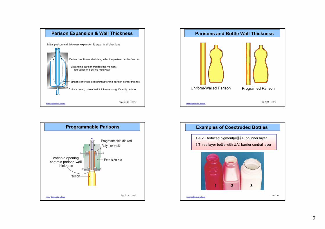
Parison Expansion & Wall Thickness
Initial parison expansion is equal in all directions wall thickness
Expanding parison freezes the moment it touches the chilled mold wall
Parison continues stretching after the parison center freezes
Parison continues stretching after the parison center freezes
As a result, corner wall thickness is significantly reduced
Figure 7.24 34/43
Uniform-Walled Parison Programed Parison
Fig. 7.22
Parisons and Bottle Wall Thickness
35/43
Variable openingcontrols parison-wall
thickness
Programmable Parisons
Fig. 7.23 36/43
Examples of Coextruded Bottles
1 & 2 Reduced pigment(颜料) on inner layer
3 Three layer bottle with U.V. barrier central layer
1 2 3
R
10
37/43
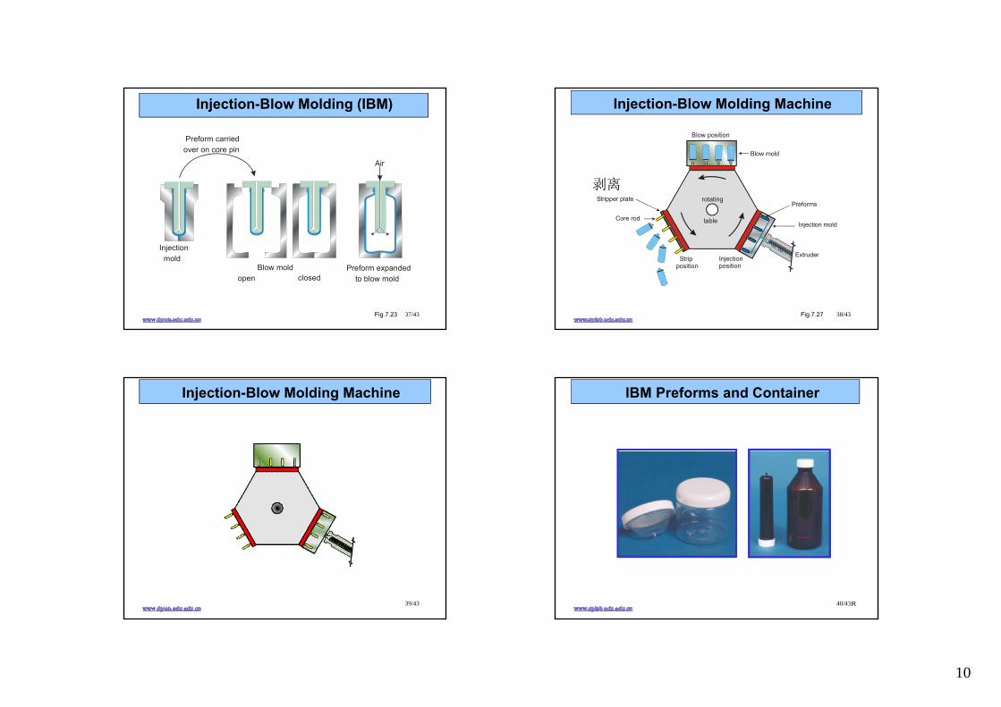
Injection-Blow Molding (IBM)
Fig.7.23
Injection mold
Blow mold open closed
Preform expanded to blow mold
Preform carriedover on core pin
Air
38/43
Injection-Blow Molding Machine
Fig.7.27
Blow position
Stripposition
Preforms
Injection mold
Blow mold
Stripper plate
ExtruderInjectionposition
rotating
tableCore rod
剥离
39/43
Injection-Blow Molding Machine
40/43
IBM Preforms and Container
R
11
41/43
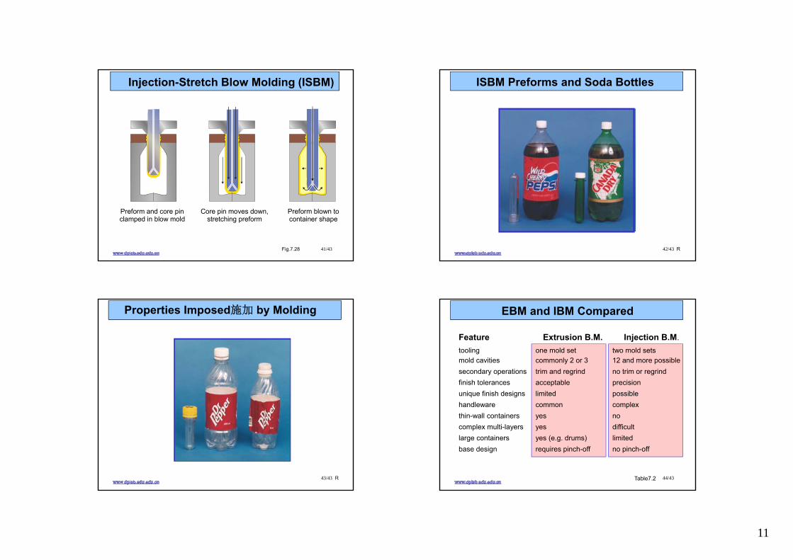
Injection-Stretch Blow Molding (ISBM)
Fig.7.28
Preform and core pinclamped in blow mold
Core pin moves down,stretching preform
Preform blown tocontainer shape
42/43
ISBM Preforms and Soda Bottles
R
43/43
Properties Imposed施加 by Molding
R 44/43
EBM and IBM Compared
tooling one mold set two mold setsmold cavities commonly 2 or 3 12 and more possiblesecondary operations trim and regrind no trim or regrindfinish tolerances acceptable precisionunique finish designs limited possiblehandleware common complexthin-wall containers yes nocomplex multi-layers yes difficultlarge containers yes (e.g. drums) limitedbase design requires pinch-off no pinch-off
Feature Extrusion B.M. Injection B.M.
Table7.2
Recommended


![Perchta Belly Slitter[1]](https://img.pdfslide.us/doc/110x75/545a8917b1af9f4a1d8b4996/perchta-belly-slitter1.jpg)