PLC INTERFACE UNIT
SIF-600INSTRUCTION MANUAL

2
PrefaceThank you for purchasing our SIF-600, PLC interface unit.This manual contains instructions for the mounting, functions, operations and notes when operating theSIF-600. To ensure safe and correct use, thoroughly read and understand this manual before using thisinstrument. To prevent accidents arising from the misuse of this instrument, please ensure the operatorreceives this manual.
Notes• This instrument should be used in accordance with the specifications described in the manual.
If it is not used according to the specifications, it may malfunction or cause a fire.• Be sure to follow all of the warnings, cautions and notices. If they are not observed, serious injury or
malfunction may occur.• The contents of this instruction manual are subject to change without notice.• Care has been taken to assure that the contents of this instruction manual are correct, but if there are any
doubts, mistakes or questions, please inform our sales department.• This instrument is designed to be installed on a DIN rail within a control panel. If it is not, measures must be
taken to ensure that the operator cannot touch power terminals or other high voltage sections.• Any unauthorized transfer or copying of this document, in part or in whole, is prohibited.• Shinko Technos CO., LTD. is not liable for any damage or secondary damage(s) incurred as a result of usingthis product, including any indirect damage.
Safety Precautions (Be sure to read these precautions before using our products.)
The safety precautions are classified into 2 categories: “Warning” and “Caution”.Depending on the circumstances, procedures indicated by Caution may cause serious results, so be sureto follow the directions for usage.
WarningProcedures which may lead to dangerous conditions and cause death or serious injury, if not carriedout properly.
Procedures which may lead to dangerous conditions and cause superficial to medium injury or physicaldamage or may degrade or damage the product, if not carried out properly.
Warning• To prevent an electric shock or fire, only Shinko or other qualified service personnel may handle theinner assembly.
• To prevent an electric shock, fire or damage to the instrument, parts replacement may only beundertaken by Shinko or other qualified service personnel.
SAFETY PRECAUTIONS• To ensure safe and correct use, thoroughly read and understand this manual before using thisinstrument.
• This instrument is intended to be used for industrial machinery, machine tools and measuringequipment. Verify correct usage after purpose-of-use consultation with our agency or main office.(Never use this instrument for medical purposes with which human lives are involved.)
• External protection devices such as protective equipment against excessive temperature rise, etc.must be installed, as malfunction of this product could result in serious damage to the system or injuryto personnel. Also proper periodic maintenance is required.
• This instrument must be used under the conditions and environment described in this manual.Shinko Technos Co., Ltd. does not accept liability for any injury, loss of life or damage occurring due tothe instrument being used under conditions not otherwise stated in this manual.
Caution with respect to Export Trade Control OrdinanceTo avoid this instrument from being used as a component in, or as being utilized in the manufacture ofweapons of mass destruction (i.e. military applications, military equipment, etc.), please investigate the endusers and the final use of this instrument.In the case of resale, ensure that this instrument is not illegally exported.
Caution

3
1. Installation Precautions
CautionThis instrument is intended to be used under the following environmental conditions
(IEC61010-1): Overvoltage category , Pollution degree 2
Ensure the mounting location corresponds to the following conditions:
• A minimum of dust, and an absence of corrosive gases
• No flammable, explosive gases
• No mechanical vibrations or shocks
• No exposure to direct sunlight, an ambient temperature of 0 to 50 (32 to 122 ) that does not change
rapidly, and no icing
• An ambient non-condensing humidity of 35 to 85%RH
• No large capacity electromagnetic switches or cables through which large current is flowing
• No water, oil or chemicals or where the vapors of these substances can come into direct contact with
the unit
• If the SIF-600 is mounted within a control panel, the ambient temperature of the unit - not the ambient
temperature of the control panel - must be kept to under 50 . Otherwise the life of electronic parts
(especially electrolytic capacitors) of the unit will be shortened.
Note: Do not install this instrument on or near flammable material even though the case of this
instrument is made of flame-resistant resin.
2. Wiring Precautions
Caution• Do not leave wire remnants in the instrument, because they could cause a fire or a malfunction.
• Use a solderless terminal with an insulation sleeve in which the M3 screw fits when wiring the SIF-600.
• Tighten the terminal screw using the specified torque. If excessive force is applied to the screw when
tightening, the terminal screw may be damaged.
• This instrument does not have a built-in power switch, circuit breaker or fuse.
It is necessary to install them near the instrument.
(Recommended fuse: Time-lag fuse, rated voltage 250 V AC, rated current 2 A)
• For a 24 V AC/DC power source, do not confuse polarity when using direct current (DC).
3. Operation and Maintenance Precautions
Warning• Do not touch live terminals. This may cause electric shock or problems in operation.
• Turn the power supply to the instrument OFF before retightening the terminal or cleaning.
Working or touching the terminal with the power switched ON may result in severe injury or death due to
Electric Shock.
• Use a soft, dry cloth when cleaning the instrument.
(Alcohol based substances may tarnish or deface the unit.)
• As the display section is vulnerable, do not strike or scratch it with a hard object or put pressure on it.

4
--- CONTENTS ---
1. Overview
1.1 Overview ----------------------------------------------------------------------------- 6
1.2 Configuration ------------------------------------------------------------------------ 6
1.3 PLC Memory Allocation Method ------------------------------------------------ 7
2. Model
2.1 Model ---------------------------------------------------------------------------------- 8
2.2 How to Read the Model Label -------------------------------------------------- 8
3. Name and Functions of the Sections ------------------------- 9
4. Mounting, Removal
4.1 Site Selection ----------------------------------------------------------------------- 10
4.2 External Dimensions (scale: mm) --------------------------------------------- 10
4.3 Mounting ----------------------------------------------------------------------------- 11
4.4 Removal ----------------------------------------------------------------------------- 13
5. Wiring
5.1 Lead Wire Solderless Terminal ------------------------------------------------ 15
5.2 Terminal Arrangement ------------------------------------------------------------ 16
5.3 Connecting Power Terminals --------------------------------------------------- 16
5.4 Connecting to a PLC
5.4.1 Connecting to a Mitsubishi PLC ---------------------------------------- 17
5.4.2 Connecting to an Omron PLC ------------------------------------------- 18
5.4.3 Connecting to a Keyence PLC ------------------------------------------ 19
5.4.4 Connecting to a Yokogawa PLC ---------------------------------------- 20
5.4.5 Connecting to a Fuji PLC ------------------------------------------------- 21
5.5 Connecting to Digital Indicating Controllers
5.5.1 Connecting to the WCL-13A --------------------------------------------- 22
5.5.2 Connecting to the DCL-33A --------------------------------------------- 23
5.5.3 Connecting to the NCL-13A --------------------------------------------- 24
5.5.4 Connecting to the ACx-13A, JCx-33A Series------------------------ 25
6. Setup ---------------------------------------------------------------------------------- 26
6.1 Shifting to Each Mode of the SIF-600
6.1.1 Communication Mode ----------------------------------------------------- 27
6.1.2 Console Software ----------------------------------------------------------- 27
6.1.3 Parameter Setting Mode -------------------------------------------------- 27
6.2 Setup via Console Software ---------------------------------------------------- 28
6.2.1 Setup Using the Flexible Address Method --------------------------- 31
6.2.2 Setup Using the Multi Address Method ------------------------------- 37
6.2.3 Setup Using the Flagless Method -------------------------------------- 44
6.2.4 Setup Using the Fixed Address Method ------------------------------ 51
6.3 Setup in the Parameter Setting Mode --------------------------------------- 58
6.3.1 Key Operation Flowchart in the Parameter Setting Mode ------- 59
6.3.2 Setting Items in the Parameter Setting Mode ----------------------- 60

5
6.4 Setup of the PLC
6.4.1 Setup of Mitsubishi PLC -------------------------------------------------- 63
6.4.2 Setup of Omron PLC ------------------------------------------------------ 67
6.4.3 Setup of Keyence PLC ---------------------------------------------------- 68
6.4.4 Setup of Yokogawa PLC -------------------------------------------------- 70
6.4.5 Setup of Fuji PLC ----------------------------------------------------------- 71
6.5 Setup of Digital Indicating Controllers ---------------------------------------- 73
7. Operation
7.1 Turn the Power ON ---------------------------------------------------------------- 74
7.2 Flexible Address Method
7.2.1 How to Read/Write Data on the PLC ----------------------------------- 76
7.2.2 Action Details and Notes -------------------------------------------------- 79
7.3 Multi Address Method
7.3.1 How to Read/Write Data on the PLC ----------------------------------- 80
7.3.2 Action Details and Notes -------------------------------------------------- 83
7.4 Flagless Method
7.4.1 How to Read/Write Data on the PLC ----------------------------------- 84
7.4.2 Action Details and Notes -------------------------------------------------- 91
7.5 Fixed Address Method
7.5.1 How to Read/Write Data on the PLC ----------------------------------- 92
7.5.2 Action Details and Notes -------------------------------------------------- 97
8. Specifications ------------------------------------------------------------------ 98
9. Troubleshooting
9.1 Communication ------------------------------------------------------------------ 101
9.2 Indication -------------------------------------------------------------------------- 101
10. Character Table -------------------------------------------------------------- 103
6
1. Overview1.1 Overview
The SIF-600 is a PLC interface unit to relay communication between a PLC and a maximum of 95
controllers (*).
The SIF-600 stores controllers’ data in the PLC register, and exchanges data using Read/Write flag
operation.
Digital indicating controllers equipped with Shinko protocol or Modbus protocol can be connected.
(*) When connecting 32 units or more, repeaters are necessary.
Shinko communication converter IF-400 can be used as a repeater.
1.2 Configuration
Configuration without Using Repeaters
(*) A maximum of 31 controllers can be connected (For the Fixed address method: Max. 20 units)
(Fig. 1.2-1)
Configuration Using Repeaters
(*1): A maximum of 30 controllers can be connected with the IF-400 (repeater) as the 31st unit.
(*2): UP to 3 units of the IF-400 (repeater) and up to 95 controllers can be connected.
(Fig. 1.2-2)
PLCs Corresponding to SIF-600
PLC manufacturer PLC model Host link unit
MELSEC
Q series, QnA series (*)
AJ71UC24, A1SJ71UC24-R2/R4/PRF
A1SJ71C24-R2/R4/PRF, QJ71C24Mitsubishi Electric Corp.
MELSEC FX series (*)
Omron Corp. SYSMAC CJ series CS1W-SCU21-V1
CJ1W-SCU21, CJ1W-SCU41
Keyence Corp. KV KV-L20V
Yokogawa Electric Corp. FA-M3 F3LC11-2N, F3LC11-1F, F3LC12-1F
Fuji Electric Co., Ltd.MICREX-SX series
NP1L-RS1, NP1L-RS2, NP1L-RS3
NP1L-RS4
(*) Models with compatible QR/QW communication commands
Each company’s PLC SIF-600 Digital indicating controllers (*)RS-422A
RS-485
RS-232C RS-485
Host link unit
Each company’s PLC SIF-600
Digital indicatingcontrollers
RS-422ARS-485
RS-232C RS-485
Host link unit
IF-400 (repeater)
Digital indicatingcontrollers
RS-485
Digital indicatingcontrollers
IF-400 (repeater)
RS-485
Max. 30 units (*1)
Max. 95 units (*2)
Max. 30 units (*1)
7
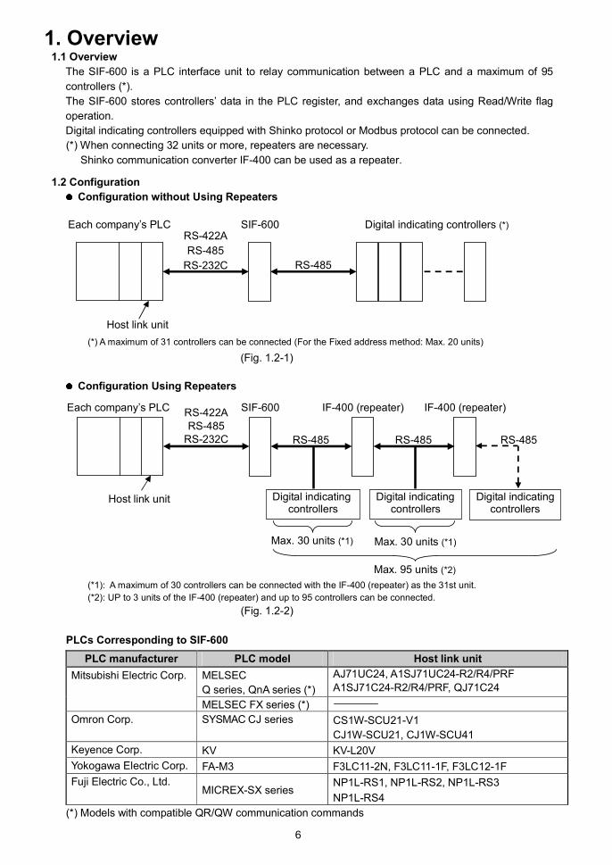
1.3 PLC Memory Allocation Method
There are 4 PLC Memory allocation methods. (Factory default value: Fixed Address method)
PLC memory allocationmethod Contents
Flexible address method Constantly updates RO (Read Only) data items.Settings of RW (Read/Write) data items are managed via the Set valuechange flag.
Multi address method Block communication command (Multiple data communicationcommand in Modbus protocol) is available.Constantly updates RO (Read Only) data items.Settings of RW (Read/Write) data items are managed via the Set valuechange flag.
Flagless method Constantly updates RO (Read Only) data items.RW (Read/Write) data items are managed without using the Set valuechange flag.
Fixed address method PLC register section is fixed for 20 units.Constantly updates RO (Read Only) data items.Settings of RW (Read/Write) data items are managed via the Set valuechange flag.
Advantages/Disadvantages of the PLC Memory Allocation Methods
PLC memoryallocationmethod
Number ofconnectablecontrollers
Advantage Disadvantage
Flexibleaddressmethod
Max. 95 units • Number of PLC register addressescan be reduced since data itemscan be set randomly.
• Initial setup (*) of the PLCis required.
• PLC data addresses changesdepending on increase/decrease of the number ofcontrollers.
Multi addressmethod
Max. 95 units • Number of PLC register addressescan be reduced since data itemscan be set randomly.
• Block communication command(Multiple data communicationcommand in Modbus protocol)can be used.
• Initial setup (*) of the PLCis required.
• Number of PLC dataaddresses changesdepending on increase/decrease of the number ofcontrollers.
Flaglessmethod
Max. 95 units • The set values can be changedeasily since the Set value changeflag is not used.[Even when settings are changedon the PLC side (or controller side),those changes will automaticallyoccur on the controller side (or PLCside)].
• Data item and instrument numbercan be changed from the PLC side.
• Initial setup (*) of the PLCis required.
• A larger number of PLCregister addresses areoccupied as the PLC data,relevant instrument numberand data item of the controllerare set.
• As the data amount isincreased, the response timebecomes slower.
Fixed addressmethod
Max. 20 units • PLC’s initial setup (*) is easierto set.
• Number of PLC data addresseswill not be changed even if thenumber of connected controllersare increased/decreased(Addresses for 20 units areconstantly needed).
• As the PLC register ispredetermined, a largernumber of PLC register isoccupied.Occupies 500-Words(20 units x 25 items).
(*) Console software (SWC-SIF01M) is used for settings.
Please download from Shinko website.
http://shinko-technos.co.jp/e/ Download To download Software

8
2. Model
2.1 Model
SIF-600
2.2 How to Read the Model Label
Model label is attached to the left side of the case.
(Fig. 2.2-1)
Model
Power supply, Power consumptionSerial number

9
3. Name and Functions of the Sections
(Fig. 3-1)
Displays (Red)
Upper display:
PLC model and communication status are indicated in the Communication mode.
Error characters flashes when communication errors occur.
Setting characters are indicated in the Parameter setting mode.
Lower display:
PLC memory allocation methods are indicated in the Communication mode.
Error codes flashes when communication errors occur.
The set values are indicated in the Parameter setting mode.
Status Indicators
PWR indicator (yellow): Lit when the power is supplied to the instrument.
ERR indicator (red): Lit when communication errors have occurred.
PLC indicator (yellow): Lit while communicating with the PLC [Serial communication Tx output
(transmitting)].
LOC indicator (yellow): Lit while communicating with the controllers [Serial communication Tx output
(transmitting)].
Keys
Increase key ( ): Increases the numeric value, or switches the selection item.
Decrease key ( ): Decreases the numeric value, or switches the selection item.
Mode key ( ): Switches the Parameter setting mode, or registers the set value.
Console communication connector:By connecting via the USB communication cable (CMB-001, sold separately), varioussetting data can be transmitted from an external computer via the Console softwareSWC-SIF01M (*).
(*) Please download from Shinko website.
http://shinko-technos.co.jp/e/ Download To download Software
Light sensor: Automatically measures and controls brightness of the displays.
Displays
(Upper display,
Lower display)
ERR indicator
Increase Key
Consolecommunicationconnector
Decrease Key
PWR indicator
LOC indicator
PLC indicator
Mode Key
Light sensor

10
4. Mounting, Removal4.1 Site Selection
CautionUse within the following temperature and humidity ranges.Temperature: 0 to 50 (32 to 122 ) (No icing), Humidity: 35 to 85%RH (Non-condensing)
If SIF-600 is mounted within a control panel, the ambient temperature of the unit - not the ambient
temperature of the control panel - must be kept to under 50 , otherwise the life of electronic parts
(especially electrolytic capacitors) of the unit will be shortened.
This instrument is intended to be used under the following environmental conditions
(IEC61010-1): Overvoltage category , Pollution degree 2
Ensure the mounting location corresponds to the following conditions:
• A minimum of dust, and an absence of corrosive gases
• No flammable, explosive gases
• No mechanical vibrations or shocks
• No exposure to direct sunlight, an ambient temperature of 0 to 50 (32 to 122 ) that does not change
rapidly
• An ambient non-condensing humidity of 35 to 85%RH
• No large capacity electromagnetic switches or cables through which large current is flowing
• No water, oil or chemicals or where the vapors of these substances can come into direct contact with
the unit
4.2 External Dimensions (scale: mm)
(Fig. 4.2-1)
Socket (sold separately)
DIN rail
30 79
108
10.8
3.3
85
3

11
4.3 Mounting
(1) Hook the upper part of the socket on the DIN rail, and mount it (A clicking sound is heard).
(Fig. 4.3-1)
CautionBefore inserting the SIF-600 into the socket, wire the unit while referring to Section “5. Wiring”
(p.15 to 26).
(2) Check that the Lock Release has been lowered.
(Fig. 4.3-2)
Hook the upper part of the
socket on the DIN rail.
Lock Release
12
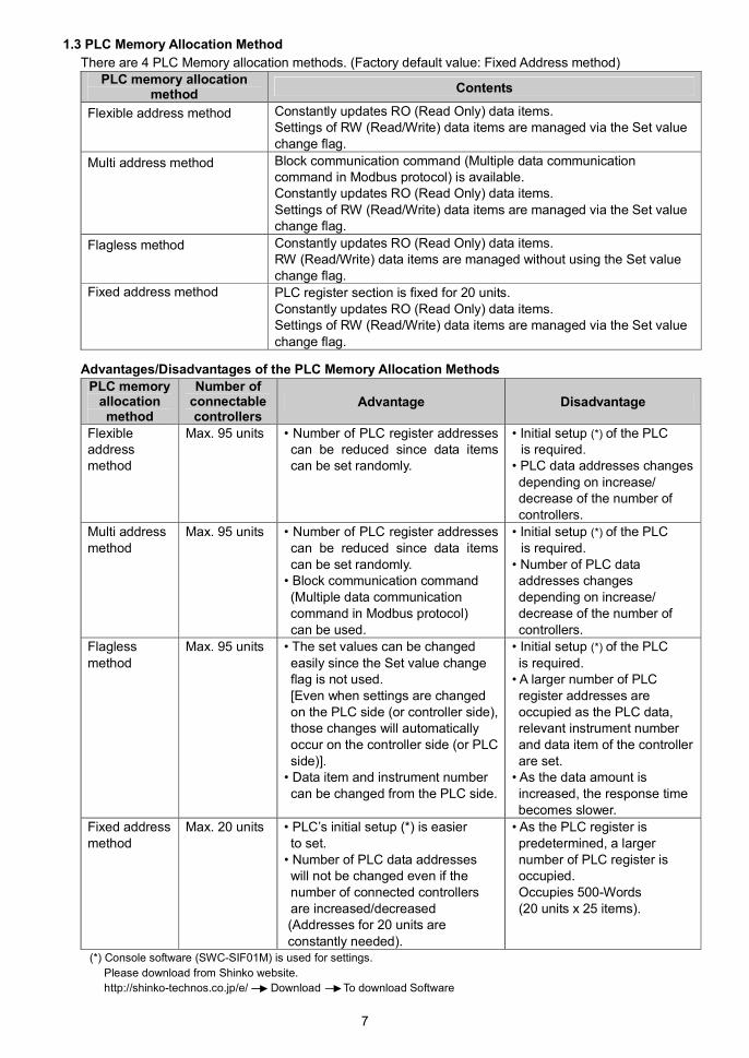
(3) Insert the SIF-600 into the socket.
(Fig. 4.3-3)
(4) Fix the SIF-600 and the socket by pushing the Lock Release up.
(Fig. 4.3-4)
When inserting, be careful about
the position of pins and slots.
Lock Release
Check that the SIF-600 and the socket
are locked by pushing the Lock Release up.

13
4.4 Removal
(1) Turn the power supply to the unit OFF.
(2) Pull the Lock Release down, and release the SIF-600 from the socket.
(Fig. 4.4-1)
(3) Separate the SIF-600 from the socket.
(Fig. 4.4-2)
Lock Release
Check that the SIF-600 and
the socket are unlocked by pulling
the Lock Release down.

14
(4) Remove the socket from the DIN rail by pulling the Socket Lock Release (at the bottom of the
socket) down.
(Fig. 4.4-3)

15
5. Wiring
WarningTurn the power supply to the instrument OFF before wiring or checking.
Working on or touching the terminal with the power switched ON may result in severe injury
or death due to Electric Shock.
Caution• Do not leave wire remnants in the instrument, because they could cause a fire or a malfunction.
• Use a solderless terminal with an insulation sleeve in which the M3 screw fits when wiring the
SIF-600.
• Tighten the terminal screw using the specified torque. If excessive force is applied to the screw
when tightening, the terminal screw may be damaged.
• This instrument does not have a built-in power switch, circuit breaker or fuse.
It is necessary to install them near the instrument.
(Recommended fuse: Time-lag fuse, rated voltage 250 V AC, rated current 2 A)
• For a 24 V AC/DC power source, do not confuse polarity when using direct current (DC).
5.1 Lead Wire Solderless Terminal
Use a solderless terminal with an insulation sleeve in which an M3 screw fits as follows.
For sockets with finger-safe & screw fall prevention functions, the ring terminals can be used.
The tightening torque should be 0.63 N•m.
Solderless
TerminalManufacturer Model
Y type Nichifu Terminal Industries CO., LTD. TMEV1.25Y-3S
Nichifu Terminal Industries CO., LTD. TMEV1.25-3Ring type
Japan Solderless Terminal MFG CO., LTD. V1.25-3
Y type Ring type
(Fig. 5.1-1) (Fig. 5.1-2)
3.2
mm
or
mo
re
5.9
mm
or
less
4 mm or less4.8 mmor more
5.9
mm
orle
ss
4 mm or less4.8 mmor more

16
5.2 Terminal Arrangement
(Fig. 5.2-1) (Fig. 5.2-2)
RS-485(PLC), RS-422A(PLC), RS-232C(PLC): Terminals for communication with PLC
For RS-422A, a terminator (200 ) is built in
between RXA and RXB.
POWER SUPPLY: Power terminals
RS-485(LOCAL): Terminals for communication with controllers, Modular jack.
Use in accordance with the controllers connected.
5.3 Connecting Power Terminals
(Fig. 5.3-1)
1234
5678
9101112
1314-
+
100 to 240 V AC
or
24 V AC/DC
1
6
5
4
3
2 NC
COM
YB(+)
YA(-)
NC
COM
1 6
Modular jack pin arrangement (SIF-600 side)RS-485 (LOCAL)

17
5.4 Connecting to a PLC
5.4.1 Connecting to a Mitsubishi PLC
RS-422A
Using the communication cable (*), connect the units.
Refer to (Fig. 5.4.1-1) below.
(Fig. 5.4.1-1)
RS-232C
Using the communication cable (*), connect the units.
Refer to (Fig. 5.4.1-2) below.
(Fig. 5.4.1-2)
(*) For the communication cable, please consult us or our agency.
Calculator link unit (AJ71UC24, A1SJ71UC24-R4, A1SJ71C24-R2/PRF)Micro PLC (FX2N-XXMR)Serial communication unit (QJ71C24)
1234
5678
9101112
1314
RD(RXD)
SD(TXD)
SG
Pin No.4
Pin No.6
Pin No.7
Pin No.8
SIF-600
Communication cable (*)
1234
5678
9101112
1314
SDA
SDB
RDA
RDB
SG
FG
SIF-600
Communication cable (*)
Calculator link unit (AJ71UC24, A1SJ71UC24-R4, A1SJ71C24-R4)Micro PLC (FX2N-XXMR)Serial communication unit (QJ71C24)

18
5.4.2 Connecting to an Omron PLC
RS-422A
Using the communication cable (*), connect the units.
Refer to (Fig. 5.4.2-1) below.
Serial communication unit
(CJ1W-SCU41)
(Fig. 5.4.2-1)
RS-232C
Using the communication cable (*), connect the units.
Refer to (Fig. 5.4.2-2) below.
Serial communication unit
(CS1W-SCU21-V1, CJ1W-SCU21)
(Fig. 5.4.2-2)
(*) For the communication cable, please consult us or our agency.
1234
5678
9101112
1314
1 SDA2 SDB6 RDA8 RDB
Shell FG
SIF-600
Communication cable (*)
1234
5678
9101112
1314
RD
SD
RS
CS
SG
SIF-600
Communication cable (*)

19
5.4.3 Connecting to a Keyence PLC
RS-422A
Using the communication cable (*), connect the units.
Refer to (Fig. 5.4.3-1) below.
Serial communication unit (KV-L20V)
(Fig.5.4.3-1)
RS-232CUsing the communication cable (*), connect the units.Refer to (Fig. 5.4.3-2) below.
Serial communication unit(KV-L20V)
(Fig. 5.4.3-2)
(*) For the communication cable, please consult us or our agency.
1234
5678
9101112
1314
3 SDA5 SDB2 RDA4 RDB1 SG
SIF-600
Communication cable (*)
1234
5678
9101112
1314
RD
SD
SG
Pin No.4
Pin No.6
Pin No.7
Pin No.8
SIF-600
Communication cable (*)

20
5.4.4 Connecting to a Yokogawa PLC
RS-422A
Using the communication cable (*), connect the units.
Refer to (Fig. 5.4.4-1) below.
Personal computer link module(F3LC11-2N)
(Fig. 5.4.4-1)
RS-232C
Using the communication cable (*), connect the units.
Refer to (Fig. 5.4.4-2) below.
Personal computer link module
(F3LC11-1F, F3LC12-1F)
(Fig. 5.4.4-2)
(*) For the communication cable, please consult us or our agency.
1234
5678
9101112
1314
RD
SD
SG
Pin No.4
Pin No.6
Pin No.7
Pin No.8
SIF-600
Communication cable (*)
1234
5678
9101112
1314
SDA
SDB
RDA
RDB
SG
SIF-600
Communication cable (*)

21
5.4.5 Connecting to a Fuji PLC
RS-422A
Using the communication cable (*), connect the units.
Refer to (Fig. 5.4.5-1) below.
(Fig. 5.4.5-1)
RS-232C
Using the communication cable (*), connect the units.
Refer to (Fig. 5.4.5-2) below.
(Fig. 5.4. 5-2)
(*) For the communication cable, please consult us or our agency.
General-purpose communication module(NP1L-RS1, NP1L-RS4)
1234
5678
9101112
1314
SDA
SDB
RDA
RDB
SG
FG
SIF-600
1234
5678
9101112
1314
RD(RXD)
SD(TXD)
SG
Pin No. 4
Pin No. 6
Pin No. 7
Pin No. 8
SIF-600
General-purpose communication module(NP1L-RS2, NP1L-RS3)
Communication cable (*)
Communication cable (*)
22
5.5 Connecting to Digital Indicating Controllers
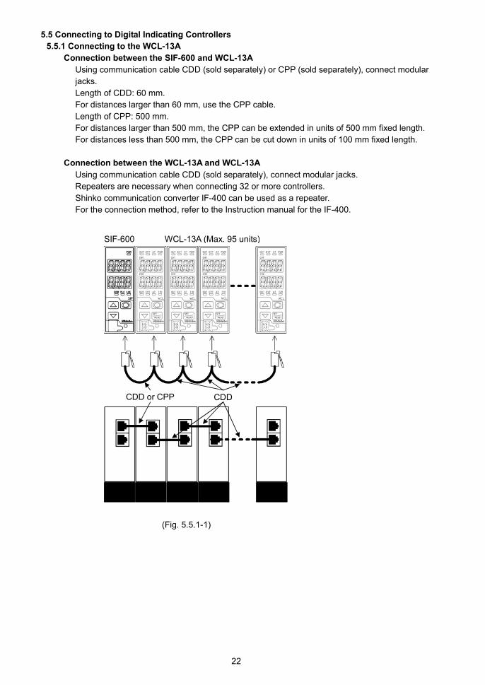
5.5.1 Connecting to the WCL-13A
Connection between the SIF-600 and WCL-13A
Using communication cable CDD (sold separately) or CPP (sold separately), connect modular
jacks.
Length of CDD: 60 mm.
For distances larger than 60 mm, use the CPP cable.
Length of CPP: 500 mm.
For distances larger than 500 mm, the CPP can be extended in units of 500 mm fixed length.
For distances less than 500 mm, the CPP can be cut down in units of 100 mm fixed length.
Connection between the WCL-13A and WCL-13A
Using communication cable CDD (sold separately), connect modular jacks.
Repeaters are necessary when connecting 32 or more controllers.
Shinko communication converter IF-400 can be used as a repeater.
For the connection method, refer to the Instruction manual for the IF-400.
(Fig. 5.5.1-1)
SIF-600 WCL-13A (Max. 95 units)
CDD or CPP CDD

23
5.5.2 Connecting to the DCL-33A
Connection between the SIF-600 and DCL-33A
Using communication cable CDD (sold separately) or CPP (sold separately), connect modular
jacks.
Length of CDD: 60 mm.
For distances larger than 60 mm, use the CPP cable.
Length of CPP: 500 mm.
For distances larger than 500 mm, the CPP can be extended in units of 500 mm fixed length.
For distances less than 500 mm, the CPP can be cut down in units of 100 mm fixed length.
Connection between the DCL-33A and DCL-33A
Using communication cable CDD (sold separately), connect modular jacks.
Repeaters are necessary when connecting 32 or more controllers.
Shinko communication converter IF-400 can be used as a repeater.
For the connection method, refer to the Instruction manual for the IF-400.
(Fig. 5.5.2-1)
SIF-600 DCL-33A (Max. 95 units)
CDD or CPP CDD
24
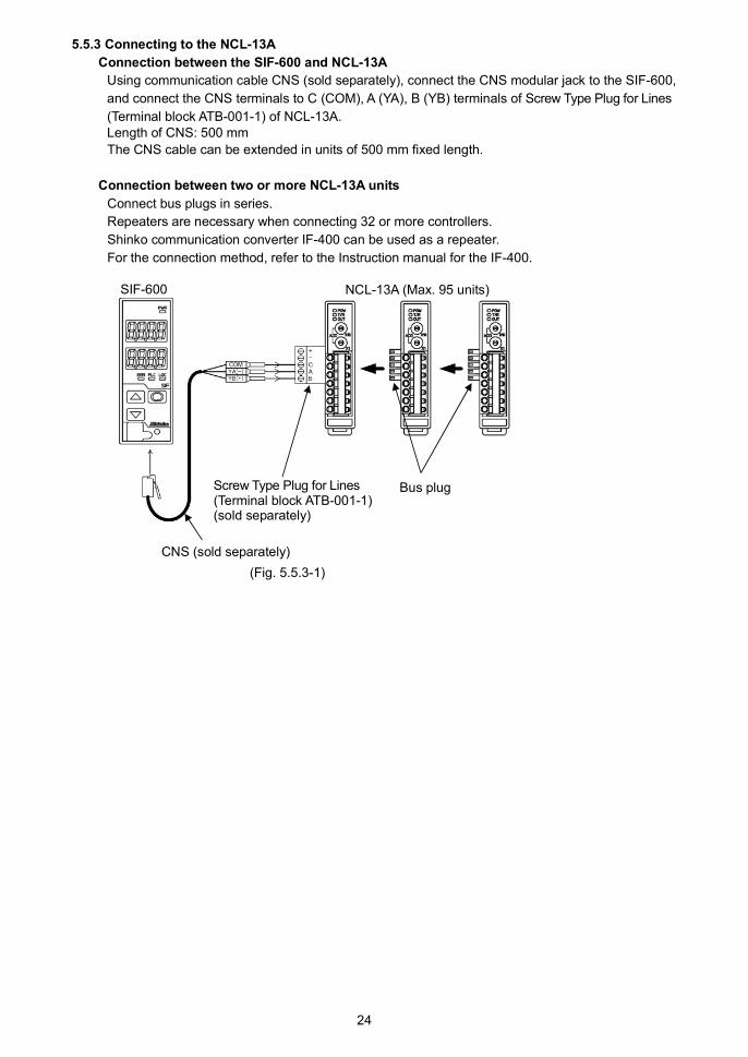
5.5.3 Connecting to the NCL-13A
Connection between the SIF-600 and NCL-13A
Using communication cable CNS (sold separately), connect the CNS modular jack to the SIF-600,
and connect the CNS terminals to C (COM), A (YA), B (YB) terminals of Screw Type Plug for Lines
(Terminal block ATB-001-1) of NCL-13A.Length of CNS: 500 mm
The CNS cable can be extended in units of 500 mm fixed length.
Connection between two or more NCL-13A units
Connect bus plugs in series.
Repeaters are necessary when connecting 32 or more controllers.
Shinko communication converter IF-400 can be used as a repeater.
For the connection method, refer to the Instruction manual for the IF-400.
(Fig. 5.5.3-1)
SIF-600 NCL-13A (Max. 95 units)
CNS (sold separately)
Screw Type Plug for Lines(Terminal block ATB-001-1)(sold separately)
Bus plug

25
5.5.4 Connecting to the ACx-13A, JCx-33A Series
Connection between the SIF-600 and ACx-13A/JCx-33A series
Using a communication cable CDM (sold separately), connect the CDM modular jack to the SIF-600,
and connect the CDM terminals to YA(-), YB(+), SG terminals of the ACx-13A/JCx-33A series.
Length of CDM: 3000 mm
The cable can be extended in units of 1000 mm fixed length.
Connection between the ACx-13A/JCx-33A
Using a shielded wire, connect YA(-) to YA(-), YB(+) to YB(+), SG to SG terminal.
Connect only one end of the shielded wire to the FG terminal so that current cannot flow to the
shielded wire.
If both ends of the shielded wire are connected to the FG terminal, the circuit will be closed between
the shielded wire and the ground. As a result, current will run through the shielded wire and this may
cause noise.
Be sure to ground FG terminal.
Recommended cable: OTSC-VB 2PX0.5SQ (made by Onamba Co., Ltd.) or equivalent (Use a
twisted pair cable.)
The JCS-33A is used as an example in the following explanation.
ACx-13A, JCx-33A series have different terminal numbers depending on the model.
For connection, refer to (Table 5.5.4-1), (Table 5.5.4-2).
Repeaters are necessary when connecting 32 or more controllers.
Shinko communication converter IF-400 can be used as a repeater.
For the connection method, refer to the Instruction manual for the IF-400.
(Table 5.5.4-1) ACx-13A Series
CDM ACS-13A ACR-13A ACD-13A
4 16 YA(-) 13 YA(-) 11 YA(-)
3 17 YB(+) 14 YB(+) 14 YB(+)
1, 6 18 SG 15 SG 17 SG
(Table 5.5.4-2) JCx-33A Series
CDM JCL-33A JCS-33A JCR-33A JCM-33A JCD-33A
4 10 YA(-) 13 YA(-) 11 YA(-) 10 YA(-) 11 YA(-)
3 11 YB(+) 14 YB(+) 14 YB(+) 13 YB(+) 14 YB(+)
1, 6 12 SG 15 SG 17 SG 14 SG 17 SG
(Fig. 5.5.4-1)
SIF-600 JCS-33A (Max. 95 units)
CDM (sold separately)
Shielded wire
Shielded wire
FG
FG

26
6. SetupSetup should be done before using this instrument, to select a PLC model, controller model, the PLC
communication parameters, etc. according to the users’ conditions.
Default value is set as shown in (Table 6-1) below.
For the SIF-600, console software and keypad operation (Parameter setting mode) are used for the setup.
For the PLC, Switches or setting tools are used for setup.
If setup has already been complete, it is not necessary to set up the SIF-600. Proceed to Section “7.
Operation (p.74)”.
(Table 6-1)
Object unit Setup method Contents of setup
Console software (SWC-SIF01M)
(*)
Sets PLC system address, PLC memory allocation
method, Data address, RO/RW, data items, etc.
See Section” 6.2 Setup via Console Software”.
(pages 28 to 57)SIF-600
Key operation (Parameter setting
mode)
Sets PLC model, controller model, PLC communica-
tion parameters, etc.
See Section “6.3 Setup in the Parameter Setting
Mode”. (pages 58 to 62).
PLC
Switches or setting tools, etc.
(Setting method differs depending
on the manufacturer or model.)
Sets communication parameters.
See Section “6.4 Setup of the PLC”. (pages 63 to 72)
(*) Please download from Shinko website.
http://shinko-technos.co.jp/e/ Download To download Software

27
6.1 Shifting to Each Mode of the SIF-600
PC
Communication Console software
(SWC-SIF01M)
Power ON
Communication Mode (3sec) Parameter Setting Mode
Communication with controllers (3sec) PLC memory allocation method
Communication with the PLC Controller
Communication protocol
Indication time
(Fig. 6.1-1)
6.1.1 Communication Mode
After the power to the SIF-600 is switched ON, the unit enters the Communication mode.
In the Communication mode, the SIF-600 communicates with the controllers and the PLC under the
conditions set by the console software and key operation (in the Parameter setting mode).
Data Read/Write is constantly performed.
6.1.2 Console Software
For the SIF-600 to communicate with the digital indicating controllers and the PLC, settings such as
PLC system address, PLC memory allocation method, PLC data address, RO/RW, data items, etc. are
carried out via the console software (SWC-SIF01M) (*).
Data can be transmitted by connecting the USB communication cable CMB-001 (sold separately).
Please download from Shinko website.
http://shinko-technos.co.jp/e/ Download To download Software
6.1.3 Parameter Setting Mode
If the key is pressed for approx. 3 seconds in the Communication mode, the unit moves to the
Parameter setting mode.
In the Parameter setting mode, PLC model, digital indicating controllers and PLC communication
parameters, etc. are set for the SIF-600 to communicate with the digital indicating controllers and the
PLC.
Use or key for settings, and register the value with the key.
If the key is held down for approx. 3 seconds, the unit reverts to the Communication mode.

28
6.2 Setup via Console Software
For the SIF-600 to communicate with the digital indicating controllers and the PLC, settings such as PLC
system address, PLC memory allocation method, PLC data address, RO/RW, data items, etc. are
carried out via the console software (SWC-SIF01M).
Data can be transmitted by connecting the USB communication cable CMB-001 (sold separately).
System configuration is shown below (Fig. 6.2-1).
(*) Ensure plugs are inserted securely.
(Fig. 6.2-1)
PLC memory allocation methods are shown in (Table 6.2-1) below.
(Table 6.2-1)
PLC memory allocation
methodContents
Flexible address method Constantly updates RO (Read Only) data items.
Manages RW (Read/Write) data item settings via the Set value
change flag.
See Section “6.2.1 Setup Using the Flexible Address Method” (pages
31 to 36).
Multi address method Block communication command (Multiple data communication
command in Modbus protocol) can be used.
Constantly updates RO (Read Only) data items.
Manages RW (Read/Write) data items via the Set value change flag.
See Section “6.2.2 Setup Using the Multi Address Method” (pages 37
to 43).
Flagless method Constantly updates RO (Read Only) data items.
Manages RW (Read/Write) data items without using the Set value
change flag.
See Section “6.2.3 Setup Using the Flagless Method” (pages 44 to
50).
Fixed address method 20 units are fixed in the PLC register.
Constantly updates RO (Read Only) data items.
Manages RW (Read/Write) data items via the Set value change flag.
See Section “6.2.4 Setup Using the Fixed Address Method” (pages
51 to 57).
PC (console software)
USB communication cable CMB-001
SIF-600
Console communication connector
PC USB port Plug
(*)

29
Factory default value: Fixed address method
PLC register section is shown in (Table 6.2-2) and (Table 6.2-3).
(Table 6.2-2) System Section
PLC address Contents
500 PLC communication status,
Controller communication status
501 Update counter
502 Set value change flag
(Table 6.2-3) Data Section
Data items correspond to the WCL-13A (Digital indicating controller).
DataNo.
PLC address RO/RW Data itemData
amountSet value changeflag number (*2)
1 1000 to 1019 RW 0001 SV 20 Read: -2/Write: 2
2 1020 to 1039 RW 0051 SV (CH2) 20 Read: -3/Write: 3
3 1040 to 1059 RW 000B Alarm 1 value (CH1) 20 Read: -4/Write: 4
4 1060 to 1079 RW 005B Alarm 1 value (CH2) 20 Read: -5/Write: 5
5 1080 to 1099 RW 0003 OUT1 proportional band
(CH1)
20 Read: -6/Write: 6
6 1100 to 1119 RW 0053 OUT1 proportional band
(CH2)
20 Read: -7/Write: 7
7 1120 to 1139 RW 0005 Integral time (CH1) 20 Read: -8/Write: 8
8 1140 to 1159 RW 0055 Integral time (CH2) 20 Read: -9/Write: 9
9 1160 to 1179 RW 0006 Derivative time (CH1) 20 Read: -10/Write: 10
10 1180 to 1199 RW 0056 Derivative time (CH2) 20 Read: -11/Write: 11
11 1200 to 1219 RW 0007 ARW (CH1) 20 Read: -12/Write: 12
12 1220 to 1239 RW 0057 ARW (CH2) 20 Read: -13/Write: 13
13 1240 to 1259 RW 0002 AT/ Auto-reset
Perform/Cancel (CH1)
20 Read: -14/Write: 14
14 1260 to 1279 RW 0052 AT/ Auto-reset
Perform/Cancel (CH2)
20 Read: -15/Write: 15
15 1280 to 1299 RW 0028Control
Allowed/Prohibited (CH1)20 Read: -16/Write: 16
16 1300 to 1319 RW 0078Control
Allowed/Prohibited (CH2)20 Read: -17/Write: 17
17 1320 to 1339 RW 0015 Sensor correction (CH1) 20 Read: -18/Write: 18
18 1340 to 1359 RW 0065 Sensor correction (CH2) 20 Read: -19/Write: 19
19 1360 to 1379 RO (*1) 0080 PV reading (CH1) 20 Read: -20/Write: 20
20 1380 to 1399 RO (*1) 0090 PV reading (CH2) 20 Read: -21/Write: 21
21 1400 to 1419 RO (*1) 0081 Output MV reading (CH1) 20 Read: -22/Write: 22
22 1420 to 1439 RO (*1) 0091 Output MV reading (CH2) 20 Read: -23/Write: 23
23 1440 to 1459 RO (*1) 0083 Status flag reading (CH1) 20 Read: -24/Write: 24
24 1460 to 1479 RO (*1) 0093 Status flag reading (CH2) 20 Read: -25/Write: 25
25 1480 to 1499 0000 Reserved 20 Read: -20/Write: 20
(*1) RO specified Data No. is Read Only item and the Set value change flag is disabled.
(*2) About Set value change flag number:
The Set value change flag in the Fixed address method is predetermined. It cannot be changed.
“Read” (Set value change flag number is negative) means that the SIF-600 reads data from the digital indicating
controllers and writes it to the PLC register section.
“Write” (Set value change flag number is positive) means that the SIF-600 reads data from the PLC register
section, and sends the setting command to the digital indicating controller.

30
When “-1” is written to the Set value change flag, the SIF-600 reads all data items (set in the PLC register section)
from the controller, and writes them to the PLC register section.
If the user’s specification is the same as the factory default value of the unit, or if setup has already
been complete, it is not necessary to set up the SIF-600. Proceed to Section “6.3 Setup in the
Parameter Setting Mode” (pages 58 to 62).
From the next page, setup method will be explained using respective PLC memory allocation methods.
31
6.2.1 Setup Using the Flexible Address Method
In the Flexible address method, RO (Read Only) data items are constantly updated.
For RW (Read/Write) data items, their settings are managed by the Set value change flag.
Data exchange occurs as follows.
RO (Read Only) data items: The SIF-600 constantly reads them from the controller, and writes them to
the PLC register.
RW (Read/Write) data items: If the Set value change flag is set, the SIF-600 sends the setting/reading
command of relevant data item and instrument number to the controller.
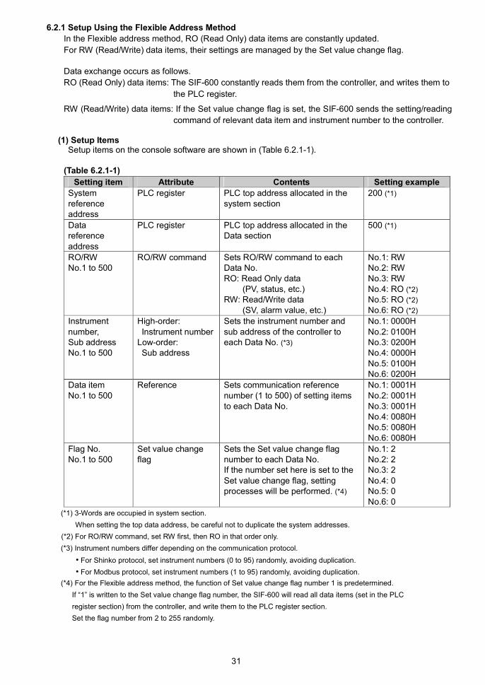
(1) Setup ItemsSetup items on the console software are shown in (Table 6.2.1-1).
(Table 6.2.1-1)
Setting item Attribute Contents Setting example
Systemreferenceaddress
PLC register PLC top address allocated in thesystem section
200 (*1)
Datareferenceaddress
PLC register PLC top address allocated in theData section
500 (*1)
RO/RWNo.1 to 500
RO/RW command Sets RO/RW command to eachData No.RO: Read Only data
(PV, status, etc.)RW: Read/Write data
(SV, alarm value, etc.)
No.1: RWNo.2: RWNo.3: RWNo.4: RO (*2)
No.5: RO (*2)
No.6: RO (*2)
Instrumentnumber,Sub addressNo.1 to 500
High-order:Instrument number
Low-order:Sub address
Sets the instrument number andsub address of the controller toeach Data No. (*3)
No.1: 0000HNo.2: 0100HNo.3: 0200HNo.4: 0000HNo.5: 0100HNo.6: 0200H
Data itemNo.1 to 500
Reference Sets communication referencenumber (1 to 500) of setting itemsto each Data No.
No.1: 0001HNo.2: 0001HNo.3: 0001HNo.4: 0080HNo.5: 0080HNo.6: 0080H
Flag No.No.1 to 500
Set value changeflag
Sets the Set value change flagnumber to each Data No.If the number set here is set to theSet value change flag, settingprocesses will be performed. (*4)
No.1: 2No.2: 2No.3: 2No.4: 0No.5: 0No.6: 0
(*1) 3-Words are occupied in system section.
When setting the top data address, be careful not to duplicate the system addresses.
(*2) For RO/RW command, set RW first, then RO in that order only.
(*3) Instrument numbers differ depending on the communication protocol.
• For Shinko protocol, set instrument numbers (0 to 95) randomly, avoiding duplication.
• For Modbus protocol, set instrument numbers (1 to 95) randomly, avoiding duplication.
(*4) For the Flexible address method, the function of Set value change flag number 1 is predetermined.
If “1” is written to the Set value change flag number, the SIF-600 will read all data items (set in the PLC
register section) from the controller, and write them to the PLC register section.
Set the flag number from 2 to 255 randomly.

32
(2) PLC System Section
The following items in (Table 6.2.1-2) are allocated in the PLC system section.
(Table 6.2.1-2)
Item Address Functions
PLC
communication status,
Controller
communication status
System reference address PLC communication status (impossible to
detect in case of no response):
B0: Sum error
B7: Other
Controller communication status:
B8: Negative acknowledgement
B9: Checksum error
B10: No response
B15: Other
Update counter System reference address
+1
Counter is updated every time
communication occurs.
0 to 65535 (Returns to 0 when 65535 is
exceeded.)
This is used to determine communication
errors with the PLC.
Set value change flag System reference address
+2
Set value change flag section.
If Set value change flag is set to any other
value except 0, corresponding data item
settings will be processed.
After setting processes are complete, the
SIF-600 returns the Set value change flag
to “0”.
(3) PLC Register Section
If setup is carried out using “(1) Setup Items” as an example, the PLC register will be described in
(Table 6.2.1-3) and (Table 6.2.1-4).
(Table 6.2.1-3) System Section
PLC address Contents
200 PLC communication status,
Controller communication status
201 Update counter
202 Set value change flag
(Table 6.2.1-4) Data Section
DataNo.
PLCaddress
RO/RWHigh-order: Instrument numberLow-order: Sub address
Dataitem
Flagnumber
1 500 RW 00H/00H 0001H 2
2 501 RW 01H/00H 0001H 2
3 502 RW 02H/00H 0001H 2
4 505 (*) RO 00H/00H 0080H 0
5 506 (*) RO 01H/00H 0080H 0
6 507 (*) RO 02H/00H 0080H 0
(*) As a PLC address, any addresses except the consecutive addresses from the top address can be set randomly.
33
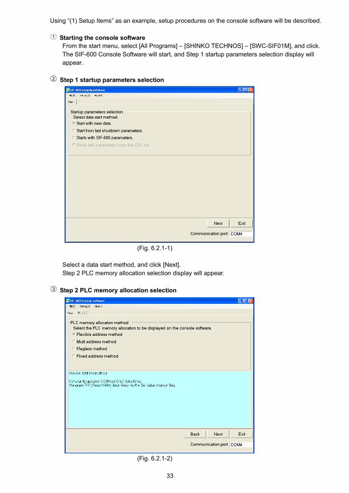
Using “(1) Setup Items” as an example, setup procedures on the console software will be described.
1 Starting the console software
From the start menu, select [All Programs] – [SHINKO TECHNOS] – [SWC-SIF01M], and click.
The SIF-600 Console Software will start, and Step 1 startup parameters selection display will
appear.
2 Step 1 startup parameters selection
(Fig. 6.2.1-1)
Select a data start method, and click [Next].
Step 2 PLC memory allocation selection display will appear.
3 Step 2 PLC memory allocation selection
(Fig. 6.2.1-2)
34
Item Setting
PLC memory allocation method Flexible address method
Select a PLC memory allocation method, and click [Next].
Step 3 system data setting display will appear.
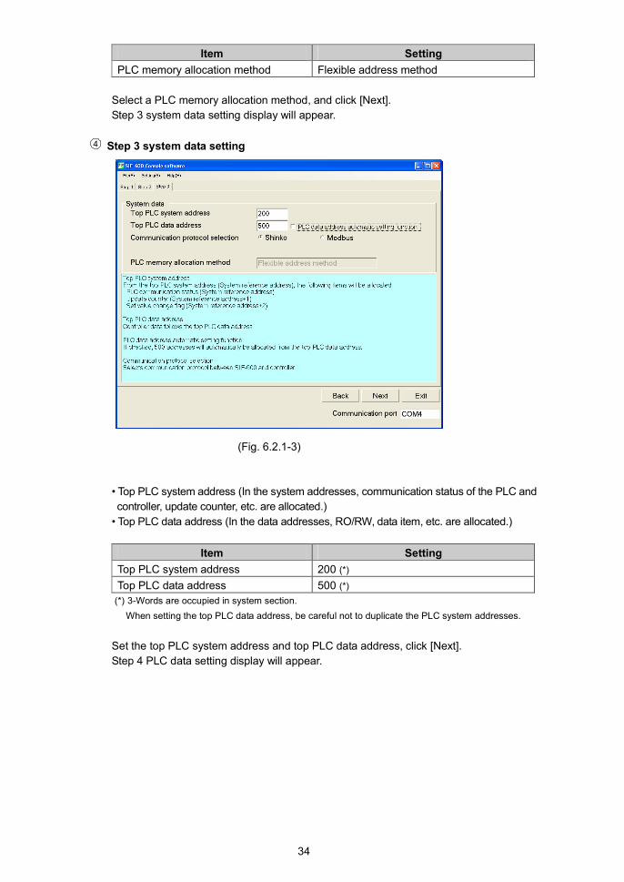
4 Step 3 system data setting
(Fig. 6.2.1-3)
• Top PLC system address (In the system addresses, communication status of the PLC and
controller, update counter, etc. are allocated.)
• Top PLC data address (In the data addresses, RO/RW, data item, etc. are allocated.)
Item Setting
Top PLC system address 200 (*)
Top PLC data address 500 (*)
(*) 3-Words are occupied in system section.
When setting the top PLC data address, be careful not to duplicate the PLC system addresses.
Set the top PLC system address and top PLC data address, click [Next].
Step 4 PLC data setting display will appear.

35
5 Step 4 PLC data setting
(Fig. 6.2.1-4)
PLC data section can be set.
Place the cursor at Data No.1, right-click and choose [Edit data] from the menu.
No.1 parameter setting display will be opened.
(Fig. 6.2.1-5) (Fig. 6.2.1-6)
Set the following.
Item Setting
PLC address 500
RO/RW RW
Instrument number 0
Sub address 0
Data item (*) 0001
Flag number 2
(*) There are 2 methods in data item setting.
1. Direct input (Fig. 6.2.1-5)
2. Select from the data item list. (Fig. 6.2.1-6)
If a controller model is selected in [Select controller], the pull-down box will appear on the right
side of the data item.
If the button on right end is clicked, data item list will appear.
Select from the list.

36
Right-click and select [Add data] from the menu, then set other PLC data section in the same
way.
(Fig. 6.2.1-7)
Click [Next].
Step 5 data transmission display will appear.
6 Step 5 data transmission
(Fig. 6.2.1-8)
Connect the USB communication cable CMB-001 (sold separately), and transmit the data.
Setup is now complete.

37
6.2.2 Setup Using the Multi Address Method
Block communication command (multiple data communication command in Modbus protocol) (*) can
be used for Multi address method.
RO (Read Only) data items are constantly updated.
For RW (Read/Write) data items, their settings are managed by the Set value change flag.
(*) Amount of multiple data (communication command) differs depending on the communication protocol.
• Shinko protocol: Max. 20
• Modbus protocol: Max. 50
Data exchange occurs as follows.
RO (Read Only) data items: The SIF-600 constantly reads from the digital indicating controllers, and
writes all data to the PLC register.
RW (Read/Write) data items: If the Set value change flag is set, the SIF-600 sends the setting/reading
command of the relevant data item and instrument number to the
controller.
(1) Setup Items
Setup items on the console software are described in (Table 6.2.2-1).
(Table 6.2.2-1)
Setting item Attribute Contents Setting example
System
reference
address
PLC register Top PLC address allocated as the
system section
200 (*1)
PLC address
No.1 to 500
PLC register Allocates PLC register addresses
for each Data No.
No. 1 : 1000 (*1) (*2)
No. 4 : 1003 (*2)
No. 7 : 2000 (*2)
No.10 : 2003 (*2)
RO/RW
No.1 to 500
RO/RW command Sets RO/RW command for each
Data No.
RO: Read Only data
(PV, status, etc.)
RW: Read/Write data
(SV, alarm value, etc.)
No. 1 : RW (*2)
No. 4 : RW (*2)
No. 7 : RO (*2) (*3)
No.10 : RO (*2) (*3)
Instrument
number,
Sub address
No.1 to 500
High-order:
Instrument number
Low-order:
Sub address
Sets an instrument number and
sub address of the controller to
each Data No. (*4)
No. 1 : 0000H (*2)
No. 4 : 0100H (*2)
No. 7 : 0000H (*2)
No.10 : 0100H (*2)
Data item
No.1 to 500
Reference Sets communication reference
number (1 to 500) of setting items
for each Data No.
No. 1 : 0001H (*2)
No. 4 : 0001H (*2)
No. 7 : 0080H (*2)
No.10 : 0080H (*2)
Flag No.
No.1 to 500
Set value change
flag
Sets the Set value change flag
number to each Data No.
If the number here is set to the
Set value change flag, setting
process will be performed. (*5)
No. 1 : 2 (*2)
No. 4 : 2 (*2)
No. 7 : 0 (*2)
No.10 : 0 (*2)
PLC data
amount
No.1 to 500
Number of PLC
registers
Sets the number of PLC registers
to each Data No.
The set data amount is allocated
in the data section consecutively.
Block communication command
(multiple data communication
command in Modbus protocol)
can be used. (*6)
No. 1 : 3 (*2)
No. 4 : 3 (*2)
No. 7 : 3 (*2)
No.10 : 3 (*2)

38
(*1) 3-Words are occupied in the system section.
When setting the top data address, be careful not to duplicate the system addresses.
(*2) For the other Data No. (No.2, 3, 8, 9, etc.) not listed in (Table 6.2.2-1), settings are not necessary as they
have been automatically occupied by the PLC data amount setting.
(*3) For RO/RW command, set RW first, then RO in that order only.
(*4) Instrument numbers differ depending on the communication protocol.
• For Shinko protocol, set instrument numbers (0 to 95) randomly, avoiding duplication.
• For Modbus protocol, set instrument numbers (1 to 95) randomly, avoiding duplication.
(*5) For the Multi address method, the function of Set value change flag number 1 is predetermined.
If “1” is written to the Set value change flag number, the SIF-600 will read all data items (set in the PLC
register section) from the controller, and write them to the PLC register section.
Set the flag number from 2 to 255 randomly.
(*6) Amount of multiple data (communication command) differs depending on the communication protocol.
• Shinko protocol: Max. 20
• Modbus protocol: Max. 50
(2) PLC System Section
The following items in (Table 6.2.2-2) are allocated in the PLC system section.
(Table 6.2.2-2)
Item Address Function
PLC
communication status,
Controller
communication status
System reference address PLC communication status (Impossible to
detect in case of no response):
B0: Sum error
B7: Other
Controller communication status:
B8: Negative acknowledgement
B9: Checksum error
B10: No response
B15: Other
Update counter System reference address
+1
Counter is updated every time
communication occurs.
0 to 65535 (Returns to 0 when 65535 is
exceeded.)
This is used to determine communication
errors with the PLC.
Set value change flag System reference address
+2
Set value change flag section.
If Set value change flag is set to any other
value except 0 (zero), corresponding data
item settings will be processed.
After setting process is complete, the
SIF-600 returns the Set value change flag
to 0 (zero).

39
(3) PLC Register Section
If setup is carried out using “(1) Setup Items” as an example, the PLC register will be described in
(Table 6.2.2-3), (Table 6.2.2-4).
(Table 6.2.2-3) System Section
PLC address Contents
200 PLC communication status,
Controller communication status
201 Update counter
202 Set value change flag
(Table 6.2.2-4) Data Section
Data No.PLC
addressRO/RW
High-order:Instrument number
Low-order:Sub address
Data
item
Flag
number
PLC data
amount
1 1000 RW 00H/00H 0001H 2 3
2
3
4 1003 RW 01H/00H 0001H 2 3
5
6
7 2000 RO 00H/00H 0080H 0 3
8
9
10 2003 RO 01H/00H 0080H 0 3
11
12

40
Using “(1) Setup Items” as an example, setup procedures on the console software will be described.
1 Starting console software
From the start menu, select [All Programs] – [SHINKO TECHNOS] – [SWC-SIF01M], and click.
The SIF-600 console software will start, and Step 1 startup parameters selection display will
appear.
2 Step 1 startup parameters selection
(Fig. 6.2.2-1)
Select a data start method, and click [Next].
Step 2 PLC memory allocation selection display will appear.
3 Step 2 PLC memory allocation selection
(Fig. 6.2.2-2)

41
Item Setting
PLC memory allocation method Multi address method
Select a PLC memory allocation method, and click [Next].
Step 3 PLC system data setting display will appear.
4 Step 3 system data setting
(Fig. 6.2.2-3)
• Top PLC system address (In the system addresses, communication status of the PLC
and controller, update counter, etc. are allocated.)
• Top PLC data address (In the data addresses, RO/RW, data item, etc. are allocated.)
Item Setting
Top PLC system address 200 (*)
Top PLC data address 1000 (*)
(*) 3-Words are occupied in system section.
When setting the top PLC data address, be careful not to duplicate the PLC system addresses.
Set the top PLC system address and top PLC data address, and click [Next].
Step 4 PLC data setting display will appear.

42
5 Step 4 PLC data setting
(Fig. 6.2.2-4)
PLC data section can be set.
Place the cursor at Data No.1, right-click and select [Edit data] from the menu.
No.1 parameter setting display will be opened.
(Fig. 6.2.2-5) (Fig. 6.2.2-6)
Set the following.
Item Setting
PLC address 1000
RO/RW RW
Instrument number 0
Sub address 0
Data item 0001
Flag number 2
PLC data amount 3
(*) There are 2 methods in data item setting.
1. Direct input (Fig. 6.2.2-5)
2. Selects from the data item list. (Fig. 6.2.2-6)
If a controller model is selected in [Select controller], the pull-down box will appear on the right
side of the data item.
If the button on right end is clicked, data item list will appear.
Select from the list.

43
Right-click and select [Add data] from the menu, then set other PLC data section in the same
way.
(Fig. 6.2.2-7)
Click [Next].
Step 5 data transmission display will appear.
6 Step 5 data transmission
(Fig. 6.2.2-8)
Connect the USB communication cable CMB-001 (sold separately), and transmit the data.
Setup is now complete.

44
6.2.3 Setup Using the Flagless Method
With the Flagless method, RO (Read Only) data items are constantly updated.
RW (Read/Write) data item settings are managed without using the Set value change flag.
Data exchange occurs as follows.
The Set value change flag is not used.
RO (Read Only) data items: The SIF-600 constantly reads from the digital indicating controllers,
and writes to the PLC register.
RW (Read/Write) data items: The SIF-600 reads controller data and relevant PLC register data
alternately, and if there is any change in data (in either PLC or
controller), the opposite side data (in either controller or PLC) will
be changed.
(1) Setup Items
Setup items on the console software are described in (Table 6.2.3-1).
(Table 6.2.3-1)
Setting item Attribute Contents Setting example
System
reference
address
PLC register Top PLC address allocated as the
system section
200 (*)
PLC address
No.1 to 500
PLC register Allocates PLC register addresses
for each Data No.
No.1 : 1000 (*1)
No.2 : 1001
No.3 : 1002
No.4 : 1003
No.5 : 1004
No.6 : 1005
RO/RW
No.1 to 500
RO/RW
command
Sets RO/RW command to each
Data No.
RO : Read Only data
(PV, status, etc.)
RW : Read/Write data
(SV, alarm value, etc.)
No.1 : RW
No.2 : RW
No.3 : RW
No.4 : RO (*2)
No.5 : RO (*2)
No.6 : RO (*2)
PLC address for
saving controller’s
instrument number
No.1 to 500
PLC register Allocates instrument number
addresses and sub address for
every Data No.
No.1 : 1500
No.2 : 1501
No.3 : 1502
No.4 : 1503
No.5 : 1504
No.6 : 1505
PLC address for
saving controller’s
data item
No.1 to 500
PLC register Allocates data item addresses
(communication reference number
of corresponding controller’s setting
item) for every Data No.
No.1 : 2000
No.2 : 2001
No.3 : 2002
No.4 : 2003
No.5 : 2004
No.6 : 2005
(*1) 3-Words are occupied in system section.
When setting the top data address, be careful not to duplicate the system addresses.
(*2) For RO/RW command, set RW first, then RO in that order only.

45
(2) PLC System Section
The following items in (Table 6.2.3-2) are allocated in the PLC system section.
(Table 6.2.3-2)
Item Address Function
PLC
communication status,
Controller
communication status
System reference address PLC communication status (Impossible to
detect in case of no response):
B0: Sum error
B7: Other
Controller communication status:
B8: Negative acknowledgement
B9: Checksum error
B10: No response
B15: Other
Update counter System reference address
+1
Counter is updated every time
communication occurs.
0 to 65535 (Returns to 0 when 65535
is exceeded.)
This is used to determine communication
errors with the PLC.
Communication item
change flag
System reference address
+2
Communication item change flag section.
Communication item change flag is set to
“1” when controller’s instrument number
or data item has been changed.
After the change process is complete, the
SIF-600 returns the flag to 0 (zero).
(3) PLC Register Section
If setup is carried out using “(1) Setup Items” as an example, the PLC register section will be
described in (Table 6.2.3-3) and (Table 6.2.3-4).
(Table 6.2.3-3) System Section
PLC address Contents
200 PLC communication status,
Controller communication status
201 Update counter
202 Communication item change flag
(Table 6.2.3-4) Data Section
Data
No.
PLC
addressRO/RW
PLC address for saving
controller’s instrument number
PLC address for saving
controller’s data item
1 1000 RW 1500 2000
2 1001 RW 1501 2001
3 1002 RW 1502 2002
4 1003 RO 1503 2003
5 1004 RO 1504 2004
6 1005 RO 1505 2005

46
For the PLC address for saving controller’s instrument number and PLC address for saving
controller’s data item, write them via the PLC ladder software.
See the writing example in (Table 6.2.3-5).
(Table 6.2.3-5) Data Section PLC Register Details
PLC address Data Contents
1500 0000H Data No.1 instrument number and sub address (*1)
High-order: Instrument number, Low-order: Sub address
1501 0100H Data No.2 instrument number and sub address (*1)
High-order: Instrument number, Low-order: Sub address
1502 0200H Data No.3 instrument number and sub address (*1)
High-order: Instrument number, Low-order: Sub address
1503 0000H Data No.4 instrument number and sub address (*1)
High-order: Instrument number, Low-order: Sub address
1504 0100H Data No.5 instrument number and sub address (*1)
High-order: Instrument number, Low-order: Sub address
1505 0200H Data No.6 instrument number and sub address (*1)
High-order: Instrument number, Low-order: Sub address
2000 0001H Data No.1 data item (*2)
2001 0001H Data No.2 data item (*2)
2002 0001H Data No.3 data item (*2)
2003 0080H Data No.4 data item (*2)
2004 0080H Data No.5 data item (*2)
2005 0080H Data No.6 data item (*2)
(*1) Instrument numbers differ depending on the communication protocol.
• For Shinko protocol, set instrument numbers (0 to 95) randomly, avoiding duplication.
• For Modbus protocol, set instrument numbers (1 to 95) randomly, avoiding duplication.
(*2) If Shinko controllers are used with Modbus protocol, take note of the following.
Modbus protocol on Shinko controllers uses Holding Register addresses.
The Holding Register addresses are created as follows.
A Shinko command data item is converted to decimal number, and the offset of 40001 is added.
The result is the Holding Register address.
(e.g.) For Data item 0001H (SV setting), write 40002 (1+40001).
For Data item 0080H (PV reading), write 40129 (128+40001).

47
Using “(1) Setup Items” as an example, setup procedures on the console software will be described.
1 Starting console software
From the start menu, select [All Programs] - [SHINKO TECHNOS] - [SWC-SIF01M], and click.
The SIF-600 console software will start, and Step 1 startup parameters selection display will
appear.
2 Step 1 startup parameters selection
(Fig. 6.2.3-1)
Select a data start method, and click [Next].
Step 2 PLC memory allocation selection display will appear.
3 Step 2 PLC memory allocation selection
(Fig. 6.2.3-2)

48
Item Setting
PLC memory allocation method Flagless method
Select a PLC memory allocation method, and click [Next].
Step 3 PLC system data setting display will appear.
4 Step 3 system data setting
(Fig. 6.2.3-3)
• Top PLC system address (In the system addresses, communication status of the PLC
and controller, update counter, etc. are allocated.)
• Top PLC data address (In the data addresses, RO/RW, data item, etc. are allocated.)
Item Setting
Top PLC system address 200 (*)
Top PLC data address 1000 (*)
(*) 3-Words are occupied in system section.
When setting the top PLC data address, be careful not to duplicate the PLC system addresses.
Set the top PLC system address and top PLC data address, click [Next].
Step 4 PLC data setting display will appear.

49
5 Step 4 PLC data setting
(Fig. 6.2.3-4)
PLC data section can be set.
Place the cursor at Data No.1, right-click and select [Edit data] from the menu.
No.1 parameter setting display will be opened.
(Fig. 6.2.3-5)
Set the following.
Item Setting
PLC address 1000
RO/RW RW
PLC address for saving controller’s
instrument number
1500
PLC address for saving controller’s
data item
2000
50
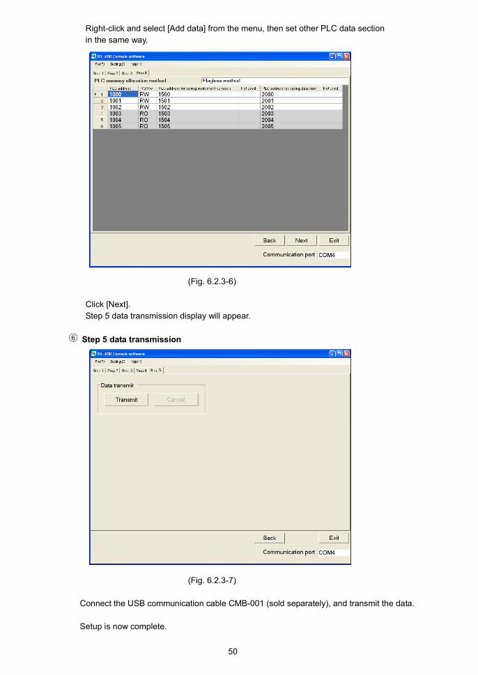
Right-click and select [Add data] from the menu, then set other PLC data section
in the same way.
(Fig. 6.2.3-6)
Click [Next].
Step 5 data transmission display will appear.
6 Step 5 data transmission
(Fig. 6.2.3-7)
Connect the USB communication cable CMB-001 (sold separately), and transmit the data.
Setup is now complete.
51
6.2.4 Setup Using the Fixed Address Method
With the Fixed address method, 20 units are fixed in the PLC register section.
RO (Read Only) data items are constantly updated.
For RW (Read/Write) data items, their settings are managed by the Set value change flag.
Data exchange occurs as follows.
RO (Read Only) data items: The SIF-600 constantly reads from the digital indicating controllers,
and writes to the PLC register.
RW (Read/Write) data items: If the Set value change flag is set, the SIF-600 sends the
setting/reading command for the predetermined data item to the
connected controllers.
Connectable controller units are up to 20 units.
PLC register section occupies 20-Words per data item. (The same applies even when less than 20
units of controllers are connected.)
(1) Setup Items
Setup items on the console software are described in (Table 6.2.4-1).
(Table 6.2.4-1)
Setting item Attribute Contents Setting example
System
reference
address
PLC register Top PLC address allocated as the
system section
500 (*1)
PLC data
address
PLC register Top PLC address allocated as the
data section
1000 (*1)(*2)
RO/RW
No.1 to 25
RO/RW command Sets RO/RW command for each
Data No.
RO: Read Only data
(PV, status, etc.)
RW: Read/Write data
(SV, alarm value, etc.)
No. 1 : RW
No. 2 : RW
No. 3 : RW
No. 4 : RW
No. 5 : RW
No. 6 : RW
No. 7 : RW
No. 8 : RW
No. 9 : RO (*3)
No.10 : RO (*3)
No.11 : RO (*3)
No.12 : RO (*3)
Data item
No.1 to 25
Reference Sets Data item [communication
reference number (1 to 25) of
setting items] for each Data No.
However, the Set value change flag
number for each Data No. will be
fixed.
No. 1 : 0001H
No. 2 : 000BH
No. 3 : 0002H
No. 4 : 0028H
No. 5 : 0051H
No. 6 : 0071H
No. 7 : 0052H
No. 8 : 0078H
No. 9 : 0080H
No.10 : 0083H
No.11 : 0090H
No.12 : 0093H(*1) 3-Words are occupied in the system section.
When setting the top data address, be careful not to duplicate the system addresses.
(*2) PLC data address setting is synchronized with the Reference address (p.62) in the Parameter setting mode.
(*3) For RO/RW command, set RW first, then RO in that order only.

52
(2) PLC System Section
The following items in (Table 6.2.4-2) are allocated in the PLC system section.
(Table 6.2.4-2)
Item Address Function
PLC communication
status,
Controller
communication status
System reference address PLC communication status (Impossible to
detect in case of no response):
B0: Sum error
B7: Other
Controller communication status:
B8: Negative acknowledgement
B9: Checksum error
B10: No response
B15: Other
Update counter System reference address
+1
Counter is updated every time
communication occurs.
0 to 65535 (Returns to 0 when 65535 is
exceeded.)
This is used to determine communication
errors with the PLC.
Set value change flag System reference address
+2
Set value change flag section.
If Set value change flag is set to any other
value except 0 (zero), corresponding data
item settings will be processed.
After setting process is complete, the
SIF-600 returns the Set value change flag
to 0 (zero).
(3) PLC Register Section
If setup is carried out using “(1) Setup Items” as an example, the PLC register section will be
described in (Table 6.2.4-3), and (Table 6.2.4-4).
(Table 6.2.4-3) System Section
PLC address Contents
500 PLC communication status,
Controller communication status
501 Update counter
502 Set value change flag

53
(Table 6.2.4-4) Data Section
Data
No.
PLC
addressRO/RW Data item
Data
amount
Set value change
flag number (*3)
1 1000 to 1019 RW 0001 CH1 SV 20 Read: -2/Write: 2
2 1020 to 1039 RW 000B CH1 Alarm 1 value 20 Read: -3/Write: 3
3 1040 to 1059 RW 0002 CH1 AT/Auto-reset
Perform/Cancel
20 Read: -4/Write: 4
4 1060 to 1079 RW 0028 CH1 Control
Allowed/Prohibited
20 Read: -5/Write: 5
5 1080 to 1099 RW 0051 CH2 SV 20 Read: -6/Write: 6
6 1100 to 1119 RW 0071 CH2 Alarm 1 value 20 Read: -7/Write: 7
7 1120 to 1139 RW 0052 CH2 AT/Auto-reset
Perform/Cancel
20 Read: -8/Write: 8
8 1140 to 1159 RW 0078 CH2 Control
Allowed/Prohibited
20 Read: -9/Write: 9
9 1160 to 1179 RO (*1) 0080 CH1 PV reading 20 Read: -10/Write: 10
10 1180 to 1199 RO (*1) 0083 CH1 Status flag
reading
20 Read: -11/Write: 11
11 1200 to 1219 RO (*1) 0090 CH2 PV reading 20 Read: -12/Write: 12
12 1220 to 1239 RO (*1) 0093 CH2 Status flag
reading
20Read: -13/Write: 13
13 1240 to 1259 (*2) (*2) 20 Read: -14/Write: 14
14 1260 to 1279 (*2) (*2) 20 Read: -15/Write: 15
15 1280 to 1299 (*2) (*2) 20 Read: -16/Write: 16
16 1300 to 1319 (*2) (*2) 20 Read: -17/Write: 17
17 1320 to 1339 (*2) (*2) 20 Read: -18/Write: 18
18 1340 to 1359 (*2) (*2) 20 Read: -19/Write: 19
19 1360 to 1379 (*2) (*2) 20 Read: -20/Write: 20
20 1380 to 1399 (*2) (*2) 20 Read: -21/Write: 21
21 1400 to 1419 (*2) (*2) 20 Read: -22/Write: 22
22 1420 to 1439 (*2) (*2) 20 Read: -23/Write: 23
23 1440 to 1459 (*2) (*2) 20 Read: -24/Write: 24
24 1460 to 1479 (*2) (*2) 20 Read: -25/Write: 25
25 1480 to 1499 (*2) (*2) 20 Read: -26/Write: 26
(*1) RO specified Data No. is Read Only item and the Set value change flag is disabled.
(*2) PLC register section is occupied up to No.25 even if it is not used.
(*3) About Set value change flag number:
The Set value change flag number in the Fixed Address method is predetermined. It cannot be changed.
“Read” (Set value change flag number is negative) means reading data from the digital indicating controllers
and writing to the PLC register section.
“Write” (Set value change flag number is positive) means reading data from the PLC register section and
sending the setting command to the digital indicating controller.
When “-1” is written to the Set value change flag, the SIF-600 reads all setting item data (set in the PLC
register section) from the controller, and writes it to the PLC register section.
With the Flexible Address and Multi Address methods, the Set value change flag 1 (positive number)
operates the SIF-600 to read all setting item data (set in the PLC register section) from controllers, and to
write it to the PLC register section.
Take note that only the Fixed Address method uses a negative Set value change flag number.

54
Using “(1) Setup Items” as an example, setup procedures on the console software will be described.
1 Starting the console software
From the start menu, select [All Programs] - [SHINKO TECHNOS] - [SWS-SIF01M], and click.
The SIF-600 console software will start, and Step 1 startup parameters selection display will
appear.
2 Step 1 startup parameters selection
(Fig. 6.2.4-1)
Select a data start method, and click [Next].
Step 2 PLC memory allocation selection display will appear.
3 Step 2 PLC memory allocation selection
(Fig. 6.2.4-2)

55
Item Setting
PLC memory allocation method Fixed address method
Select a PLC memory allocation method, and click [Next].
Step 3 system data setting display will appear.
4 Step 3 system data setting
(Fig. 6.2.4-3)
• Top PLC system address (In the system addresses, communication status of the PLC
and controller, update counter, etc. are allocated.)
• Top PLC data address (In the data addresses, RO/RW, data item, etc. are allocated.)
Item Setting
Top PLC system address 500 (*)
Top PLC data address 1000 (*)
(*) 3-Words are occupied in system section.
When setting the top PLC data address, be careful not to duplicate the PLC system addresses.
Set the top PLC system address and top PLC data address, click [Next].
Step 4 PLC data setting display will appear.

56
5 Step 4 PLC data setting
(Fig. 6.2.4-4)
PLC data section can be set.
20-Words are occupied for every Data No. (The same applies even when the number
of connected units is less than 20.)
Flag number is also fixed.
Place the cursor at Data No.1, right-click and select [Edit data] from the menu.
No.1 parameter setting display will be opened.
(Fig. 6.2.4-5) (Fig. 6.2.4-6)
Set the following.
Item Setting
RO/RW RW
Data item 0001
(*) There are 2 methods in data item setting.
1. Direct input (Fig. 6.2.4-5)
2. Selects from the data item list. (Fig. 6.2.4-6)
If a controller model is selected in [Select controller], the pull-down box will appear on the right
side of the data item.
If the button on right end is clicked, data item list will appear.
Select from the list.
57
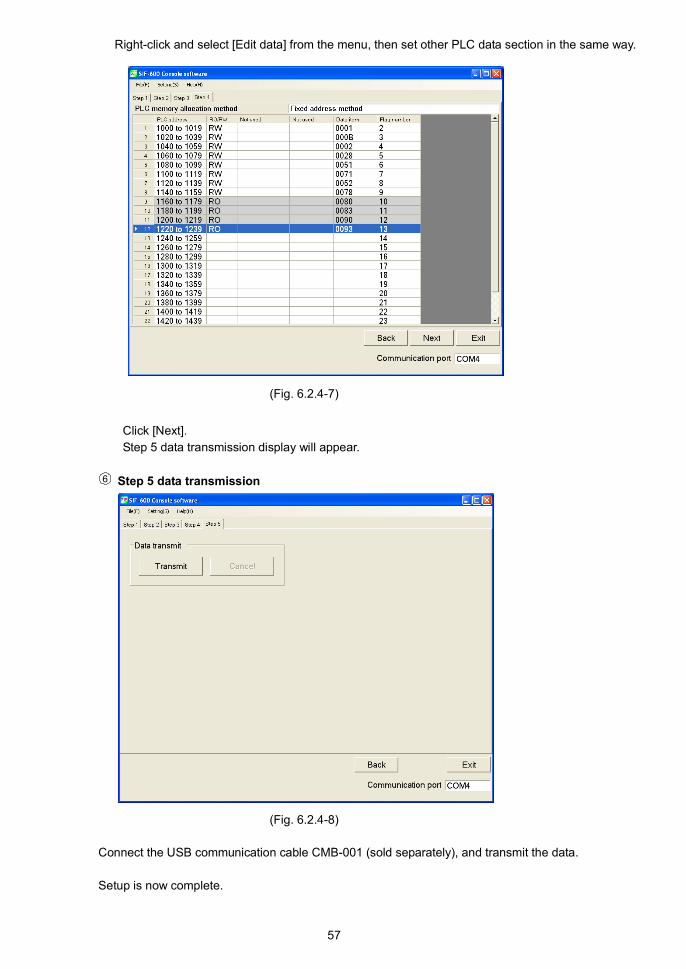
Right-click and select [Edit data] from the menu, then set other PLC data section in the same way.
(Fig. 6.2.4-7)
Click [Next].
Step 5 data transmission display will appear.
6 Step 5 data transmission
(Fig. 6.2.4-8)
Connect the USB communication cable CMB-001 (sold separately), and transmit the data.
Setup is now complete.

58
6.3 Setup in the Parameter Setting Mode
Default value is set as shown in (Table 6.3-1) below.
If the users’ specification is the same as the default value of the SIF-600, or if setup has already been
complete, it is not necessary to set up the SIF-600. Proceed to Section “6.4 Setup of the PLC” (pages
63 to 72).
(Table 6.3-1)
Setting item Factory default value
PLC Memory allocation method Fixed address method
Controller Communication protocol Shinko protocol
Controller Communication speed 9600bps
Controller Data length 7 bits
Controller Parity Even
Controller Stop bit 1 bit
PLC Model Mitsubishi MELSEC
D register QR/QW command
PLC Instrument number 0
PLC Communication speed 9600bps
PLC Data length 7 bits
PLC Parity Even
PLC Stop bit 1 bit
Number of connected controllers (*1) 1 unit
Reference address (*1) (*2) 03E8H (1000)
Auto-light function Disabled
Indication time 00.00 (Remains lit)
(*1) Indicated when Fixed address method is selected in [PLC memory allocation method] on the console software.
(*2) Reference address can be set in units of 500 in hexadecimal.
(e.g.) 500 (01F4H)
1000 (03E8H)

59
6.3.1 Key Operation Flowchart in the Parameter Setting Mode
To enter the Parameter setting mode, press the key for 3 seconds in the Communication mode.
To communicate with the PLC and digital indicating controllers, set the PLC memory allocation method,
PLC model, communication parameters of the controller and PLC, etc. in the Parameter setting mode.
Use the or key for settings (selections), and use the key to register set values.
To return to the Communication mode, hold down the key for 3 seconds.
Power ON
Communication Mode
(3 sec)
Parameter Setting Mode
PLC PLC
Memory allocation method Model
Controller PLC
Communication protocol Instrument number
Controller PLC
Communication speed Communication speed
Controller PLC
Data length Data length
Controller PLC
Parity Parity
Controller PLC
Stop bit Stop bit
Controller
Number of connected units(*1)
Reference address (*1)(*2)
Auto-light function
Indication time
Setting item:
Upper left: Indicates setting item characters
on the Upper display.
Lower left: Indicates factory default value
on the Lower display.
(*1) Indicated when Fixed address method is
selected in [PLC memory allocation
method] on the console software.
(*2) Reference address can be set in units of
500 in hexadecimal.
(e.g.) 500 (01F4H)
1000 (03E8H)

60
6.3.2 Setting Items in the Parameter Setting Mode
Displays Name, Function, Setting Range Factory Default Value
PLC Memory allocation method Fixed address method
• Indicates a method selected in [PLC memory allocation method] on the
console software.
For the PLC memory allocation methods, see the (Table 6.3.2-1) below.
(Table 6.3.2-1)
DisplaysPLC memory
allocationContents
Flexible
address
method
Constantly updates RO (Read Only) data
items.
Manages RW (Read/Write) data item settings
via the Set value change flag.
Multi
address
method
Block communication command (multiple data
communication command in Modbus protocol)
can be used.
Constantly updates RO (Read Only) data
items.
Manages RW (Read/Write) data item settings
via the Set value change flag.
Flagless
method
Constantly updates RO (Read Only) data
items.
Manages RW (Read/Write) data item settings
without using the Set value change flag.
Fixed
address
method
20 units are fixed in the PLC register section.
Constantly updates RO (Read Only) data
items.
Manages RW (Read/Write) data item settings
via the Set value change flag.
Controller Communication protocol Shinko protocol
• Selects communication protocol for communication with the controller.
• Selection item
: Shinko Protocol
: Modbus ASCII
: Modbus RTU
Controller Communication speed 9600bps
• Selects communication speed for communication with the controller.
• Selection item
: 9600bps
: 19200bps
: 38400bps
Controller Data length 7 bits
• Selects the data length for communication with the controller.
• Selection item
: 7 bits
: 8 bits
Controller Parity Even
• Selects the parity for communication with the controller.
• Selection item
: No parity
: Even
: Odd

61
Displays Name, Function, Setting Range Factory Default Value
Controller Stop bit 1 bit
• Selects stop bit for communication with the controller.
• Selection range
: 1 bit
: 2 bits
PLC Model Mitsubishi MELSEC
D register QR/QW command
• Selects a PLC model and its communication type.
• Selection item
: Mitsubishi MELSEC D register QR/QW command
: Mitsubishi MELSEC R register QR/QW command
: Omron SYSMAC CJ series
: Keyence KV
: Yokogawa FA-M3
: Fuji MICREX-SX series
PLC Instrument number 0
• Sets instrument number of the PLC to be connected.
• Setting range
0 to 99
PLC Communication speed 9600bps
• Selects communication speed for communication with the PLC.
• Selection item
: 9600bps
: 19200bps
: 38400bps
PLC Data length 7 bits
• Selects data length for communication with the PLC.
• Selection item
: 7 bits
: 8 bits
PLC Parity bit Even
• Selects parity bit for communication with the PLC.
• Selection item
: No parity
: Even
: Odd
PLC Stop bit 1 bit
• Selects stop bit for communication with the PLC.
• Selection item
: 1 bit
: 2 bits

62
Displays Name, Function, Setting Range Factory Default Value
Controller Number of connected units 1 unit
• Sets the number of controllers to be connected.
Available when Fixed address method is selected as a PLC memory allocation
method on the console software.
• Setting range: 1 to 20 units
Reference address 03E8H (1000)
• Sets the register reference address for data reading/writing.
Available when Fixed address method is selected in [PLC memory allocation
method] on the console software.
• Setting range: 0000H to FFDCH (0 to 65500)
Reference address is synchronized with PLC data address (p.51) of the
console software.
PLC data address on the console software can be set randomly. However,
reference addresses are set in units of 500 using hexadecimal numbers as in
(Table 6.3.2-2).
(Table 6.3.2-2)
Decimal Hexadecimal
0 0000H
500 01F4H
1000 03E8H
1500 05DCH
2000 07D0H
2500 09C4H
3000 0BB8H
3500 0DACH
4000 0FA0H
4500 1194H
5000 1388H
5500 157CH
6000 1770H
Auto-light function Disabled
• Selects Auto-light function Enabled/Disabled.
• : Disabled
: Enabled
Indication time 00.00 (Remains lit)
• Sets the indication time of the displays from the final key operation till
displays go off in the Communication mode. (Status indicators remain lit.)
Displays remain lit when setting to 00.00.
Displays light when any key is pressed while in unlit status.
• Setting range:
00.00 (Remains lit)
00.01 to 60.00 (Minutes.Seconds)

63
6.4 Setup of the PLC
6.4.1 Setup of Mitsubishi PLC
(1) Setup of Calculator link unit (AJ71UC24)
1 Sets the transmission control procedure (protocol)
and RS-422/RS-232C control procedure.
Set to 8 (Format 4).2 Sets the instrument number of the tens digit (x10).
Set the number to 0.3 Sets the instrument number of the ones digit (x1).
Set the number to 0.4 Sets the transmission specifications.
See (Table 6.4.1-1).
Set the items, excluding baud rate, to .
(Fig. 6.4.1-1)
(Table 6.4.1-1)
Setting switch Setting item Setting switch ON Setting switch OFF
SW11 Main channel RS-422 RS-232C
SW12 Data bit 8 bits 7 bits
Baud rate 9600bps 19200bps
SW13 ON OFF
SW14 Communication speed OFF ON
SW15 ON ON
SW16 Parity Yes/No Yes No
SW17 Even/Odd parity Even Odd
SW18 Stop bit 2 bits 1 bit
SW21 Checksum Yes/No Yes No
SW22 Writing during RUN Possible Impossible
SW23 Calculator link/Multi-drop link Calculator link Multi-drop link
SW24 Not used
STATION NO.x10
MODE
STATION NO.x1
SW11
SW12
SW13
SW14
SW15
SW16
SW17
SW18
SW21
SW22
SW23
SW24
ON
ON
4
3
1
2
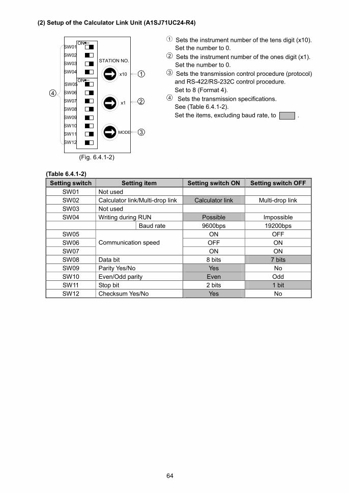
64
(2) Setup of the Calculator Link Unit (A1SJ71UC24-R4)
1 Sets the instrument number of the tens digit (x10).
Set the number to 0.2 Sets the instrument number of the ones digit (x1).
Set the number to 0.3 Sets the transmission control procedure (protocol)
and RS-422/RS-232C control procedure.
Set to 8 (Format 4).4 Sets the transmission specifications.
See (Table 6.4.1-2).
Set the items, excluding baud rate, to .
(Fig. 6.4.1-2)
(Table 6.4.1-2)
Setting switch Setting item Setting switch ON Setting switch OFF
SW01 Not used
SW02 Calculator link/Multi-drop link Calculator link Multi-drop link
SW03 Not used
SW04 Writing during RUN Possible Impossible
Baud rate 9600bps 19200bps
SW05 ON OFF
SW06 OFF ON
SW07
Communication speed
ON ON
SW08 Data bit 8 bits 7 bits
SW09 Parity Yes/No Yes No
SW10 Even/Odd parity Even Odd
SW11 Stop bit 2 bits 1 bit
SW12 Checksum Yes/No Yes No
x10
x1
MODE
STATION NO.
ONSW05
SW06
SW07
SW08
SW09
SW10
SW11
SW12
ONSW01
SW02
SW03
SW04
4
3
1
2
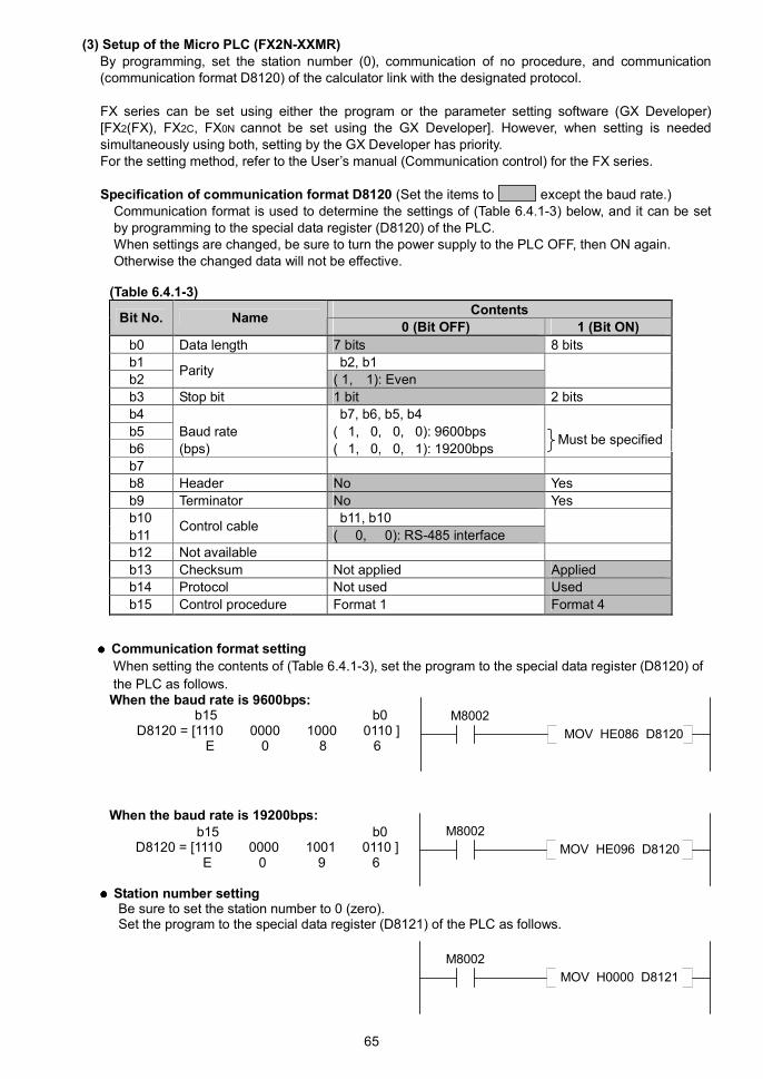
65
(3) Setup of the Micro PLC (FX2N-XXMR)By programming, set the station number (0), communication of no procedure, and communication(communication format D8120) of the calculator link with the designated protocol.
FX series can be set using either the program or the parameter setting software (GX Developer)[FX2(FX), FX2C, FX0N cannot be set using the GX Developer]. However, when setting is neededsimultaneously using both, setting by the GX Developer has priority.For the setting method, refer to the User’s manual (Communication control) for the FX series.
Specification of communication format D8120 (Set the items to except the baud rate.)Communication format is used to determine the settings of (Table 6.4.1-3) below, and it can be setby programming to the special data register (D8120) of the PLC.When settings are changed, be sure to turn the power supply to the PLC OFF, then ON again.Otherwise the changed data will not be effective.
(Table 6.4.1-3)
ContentsBit No. Name
0 (Bit OFF) 1 (Bit ON)
b0 Data length 7 bits 8 bits
b1 b2, b1
b2Parity
( 1, 1): Even
b3 Stop bit 1 bit 2 bits
b4 b7, b6, b5, b4
b5 Baud rate ( 1, 0, 0, 0): 9600bps
b6 (bps) ( 1, 0, 0, 1): 19200bps
b7
b8 Header No Yes
b9 Terminator No Yes
b10 b11, b10
b11Control cable
( 0, 0): RS-485 interface
b12 Not available
b13 Checksum Not applied Applied
b14 Protocol Not used Used
b15 Control procedure Format 1 Format 4
Communication format setting
When setting the contents of (Table 6.4.1-3), set the program to the special data register (D8120) of
the PLC as follows.When the baud rate is 9600bps:
b15 b0D8120 = [1110 0000 1000 0110 ]
E 0 8 6
When the baud rate is 19200bps:b15 b0
D8120 = [1110 0000 1001 0110 ]E 0 9 6
Station number settingBe sure to set the station number to 0 (zero).Set the program to the special data register (D8121) of the PLC as follows.
MOV HE086 D8120
M8002
MOV HE096 D8120
M8002
Must be specified
MOV H0000 D8121
M8002
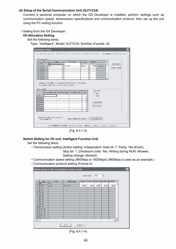
66
(4) Setup of the Serial Communication Unit (QJ71C24)
Connect a personal computer on which the GX Developer is installed, perform settings such as
communication speed, transmission specifications and communication protocol, then set up the unit
using the PC writing function.
• Setting from the GX Developer:
I/O Allocation Setting
Set the following items.
Type: “Intelligent”, Model: QJ71C24, Number of points: 32
(Fig. 6.4.1-3)
Switch Setting for I/O unit, Intelligent Function Unit
Set the following items.
• Transmission setting (Action setting: Independent, Data bit: 7, Parity: Yes (Even),
Stop bit: 1, Checksum code: Yes, Writing during RUN: Allowed,
Setting change: Allowed)
• Communication speed setting (9600bps or 19200bps) (9600bps is used as an example.)
• Communication protocol setting (Format 4)
(Fig. 6.4.1-4)

67
6.4.2 Setup of Omron PLC
Setup of the Serial Communication Unit (CS1W-SCU21-V1, CJ1W-SCU21, CJ1W-SCU41)
For setting methods, refer to User’s manual (Man. No. SBCD-300G) for Serial communication unit.
(1) Turn “TERM” (terminator ON/OFF switch) ON, and set “WIRE” (2-wire/4-wire switch) to 4.
[This setting is only for the “CJ1W-SCU41”.
For the CS1W-SCU21-V1, CJ1W-SCU21, go to step (2).]
(2) Connect to a PC, and start the CX-Programmer.
(3) Create I/O table of the PC while off-line (Fig. 6.4.2-1).
Select [CS/CJ/CPU SIO unit] – [Serial Communication Unit] – [Unit number].
(4) Set the allocation DM of the serial communication unit. (Fig. 6.4.2-2)
Set the allocation DM by programming the on-line connection and action mode.
(e.g.) When installing the serial communication unit next to the CPU unit, and when UNIT No.
is set to “0”:
D30000 is set to 8500H (random setting, host link communication, Data bit: 7 bits,
Stop bit: 2 bits, Parity: Yes/Even).
D30001 is set to 0007H (19200bps).
(Fig. 6.4.2-1)
(Fig. 6.4.2-2)
(5) Transmit the following to the CPU unit.
Transmit the program, PC system setting and I/O table by clicking ”Transmit [PC PC]”.

68
6.4.3 Setup of Keyence PLC
Setup of the Serial Communication Unit (KV-L20V)
For setting methods, refer to User’s manual for Serial communication unit KV-L20V.
(1) Set the terminator using the terminator selection switch (TERM.)
When Port 2 in RS-232C is used, set it to OFF.
When Port 2 in RS-422A and RS-485 is used, set it to ON.
(2) Connect a PC, and start the KV STUDIO (Ver.4 or later), and start the Unit Editor.
(Fig. 6.4.3-1)
(Fig. 6.4.3-2)
Select the KV-L20V on the Unit Editor, and allocate the top DM number and the top relay number.

69
(3) Set details of the KV-L20V in the Unit location section.
(Fig. 6.4.3-3)
The setting items in gray are fixed, so they cannot be set.
Set the following setting items.
Setting item Set value
Operation mode KV mode (Host link)
Baud rate 9600bps, 19200bps, 38400bps (Must be specified.)
(4) Press the Enter Key.
The setting contents will be registered.
(5) Click [OK].
The Unit Editor will be closed.

70
6.4.4 Setup of Yokogawa PLC
Setup of the Personal Computer Link Module (F3LC11-2N)
(1) Sets the Station number setting switch (tens digit). (*)
(2) Sets the Station number setting switch (ones digit). (*)
(3) Sets the Terminator switch. Select “4-WIRE”.
(4) Sets the Transmission speed setting switch. For baud rate, set it to either 9600bps or 19200bps.
(5) Sets the Data setting switch. Refer to (Table 6.4.4-1).
Set to .
(*) For the Station number setting switch, set a value larger than 0 for the ones digit and tens digit.
Avoid 0 (zero) because 0 for the ones and tens digits are CPU unit numbers.
(Table 6.4.4-1)
Number Function Setting switch OFF Setting switch ON
1 Data bit 7 bits 8 bits
2 Parity No Yes
3 Odd/Even parity Odd Even
4 Stop bit 1 bit 2 bits
5 Checksum No Yes
6 End of text (CR) No Yes
7 Protection function No Yes
8 OFF

71
6.4.5 Setup of Fuji PLC
Setup of General-purpose Communication Module
For setting methods, refer to User’s manual for MICREX-SX series, General-purpose
Communication Module.
NP1L-RS1:
1 Set the port (RS-232C or RS-485), for connecting to
the SIF-600 to Loader (*) using the MODE switch.
(*) If the port is set to Loader, communication specifications
will be fixed as follows.
Speed: 38400bps
Data length: 8 bits
Stop bit: 1
Parity: Even
2 When using RS-485 standard, set the RS-485 station
number with the RS-485 No. switch.
3 When using RS-485 standard, set to “4-wire
Termination Resistance ON” with the RS-485
Termination Resistance ON/OFF switch.
(Fig. 6.4.5-1)
NP1L-RS2:
1 Set the port (RS-232C), for connecting to the SIF-600
to Loader (*) using the MODE switch.
(*) If the port is set to Loader, communication specifications
will be fixed as follows.
Speed: 38400bps
Data length: 8 bits
Stop bit: 1
Parity: Even
(Fig. 6.4.5-2)
1
2
3
1

72
NP1L-RS4
1 Set the port (RS-485), for connecting to the SIF-600 to
Loader (*) using the MODE switch.
(*) If the port is set to Loader, communication specifications
will be fixed as follows.
Speed: 38400bps
Data length: 8 bits
Stop bit: 1
Parity: Even
2 Set the RS-485 station number using the RS-485 No.
switch.
3 Set to “4-wire Termination Resistance ON” using the
RS-485 Termination Resistance ON/OFF switch.
(Fig. 6.4.5-3)
1
2
3
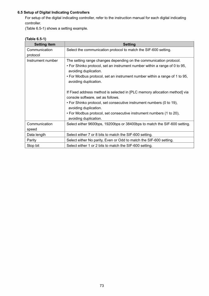
73
6.5 Setup of Digital Indicating Controllers
For setup of the digital indicating controller, refer to the instruction manual for each digital indicating
controller.
(Table 6.5-1) shows a setting example.
(Table 6.5-1)
Setting item Setting
Communication
protocol
Select the communication protocol to match the SIF-600 setting.
Instrument number The setting range changes depending on the communication protocol.
• For Shinko protocol, set an instrument number within a range of 0 to 95,
avoiding duplication.
• For Modbus protocol, set an instrument number within a range of 1 to 95,
avoiding duplication.
If Fixed address method is selected in [PLC memory allocation method] via
console software, set as follows.
• For Shinko protocol, set consecutive instrument numbers (0 to 19),
avoiding duplication.
• For Modbus protocol, set consecutive instrument numbers (1 to 20),
avoiding duplication.
Communication
speed
Select either 9600bps, 19200bps or 38400bps to match the SIF-600 setting.
Data length Select either 7 or 8 bits to match the SIF-600 setting.
Parity Select either No parity, Even or Odd to match the SIF-600 setting.
Stop bit Select either 1 or 2 bits to match the SIF-600 setting.
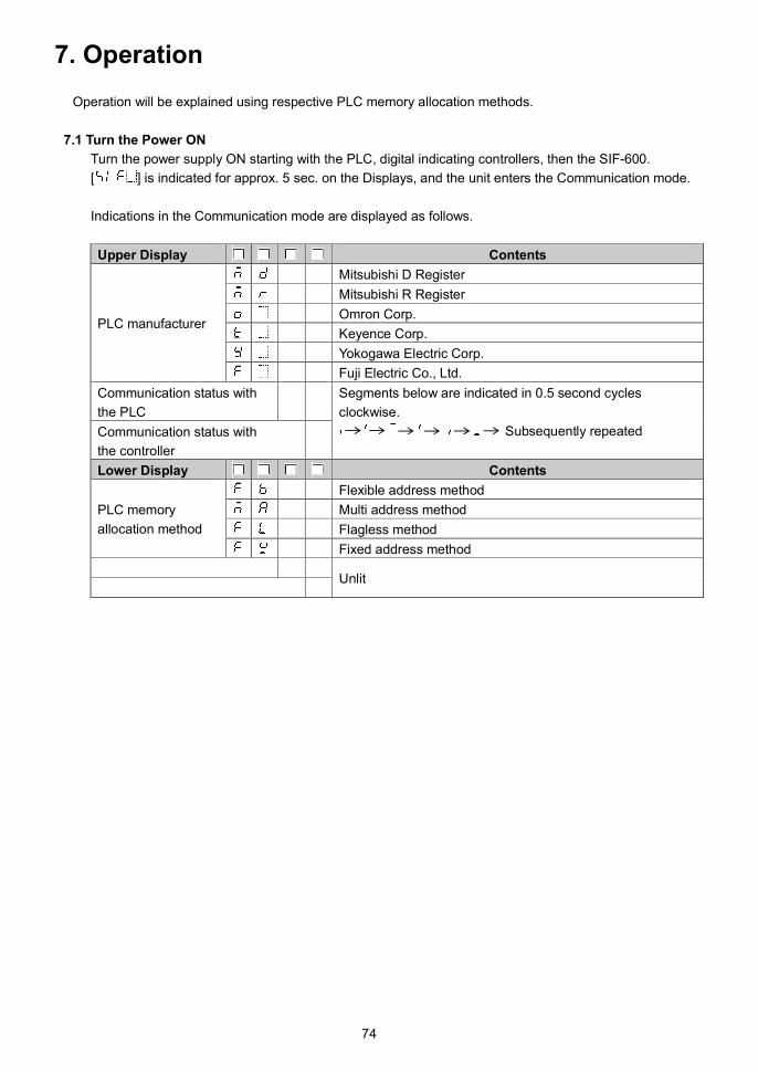
74
7. Operation
Operation will be explained using respective PLC memory allocation methods.
7.1 Turn the Power ON
Turn the power supply ON starting with the PLC, digital indicating controllers, then the SIF-600.
[ ] is indicated for approx. 5 sec. on the Displays, and the unit enters the Communication mode.
Indications in the Communication mode are displayed as follows.
Upper Display Contents
Mitsubishi D Register
Mitsubishi R Register
Omron Corp.
Keyence Corp.
Yokogawa Electric Corp.
PLC manufacturer
Fuji Electric Co., Ltd.
Communication status with
the PLC
Communication status with
the controller
Segments below are indicated in 0.5 second cycles
clockwise.
Subsequently repeated
Lower Display Contents
Flexible address method
Multi address method
Flagless method
PLC memory
allocation method
Fixed address method
Unlit

75
Indications of communication errors are shown below.
Upper Display Contents
Mitsubishi D register
Mitsubishi R register
Omron Corp.
Keyence Corp.
Yokogawa Electric Corp.
PLC manufacturer
Fuji Electric Co., Ltd.
Communication status with
the PLC
Communication status with
the controller
flashes in 0.5 second cycles.After a communication error occurs, error indicationcontinues for 10 seconds.Unlit when the unit reverts to normal.
Lower Display Contents
Flexible address method
Multi address method
Flagless method
PLC memory
allocation method
Fixed address method
PLC side communication
error code (Table 7.1-1)(*1)
Controller side communication
error code (Table 7.1-2)(*2)
Error codes to flashes in 0.5 second cycles.
When error codes are duplicated, codes flash in numeric
order every 1 second.
After a communication error occurs, error indicationcontinues for 10 seconds.
Unlit when the unit reverts to normal.
(*1) PLC Side Communication Error Code
(Table 7.1-1)
Communication
error codeContents
Parity error
Sum error
No response
, , : Reserved
(*2) Controller Side Communication Error Code
(Table 7.1-2)
Communication
error codeContents
Parity error
Negative acknowledgement
Sum error
No response
, : Reserved

76
7.2 Flexible Address Method
In this method, data exchange occurs under the conditions set via the console software as follows.
RO (Read Only) data items: The SIF-600 reads from the digital indicating controller, and writes
to the PLC register.
RW (Read/Write) data items: If the Set value change flag is set, the SIF-600 sends the setting/reading
command for the relevant data item and instrument number to the
controller.
7.2.1 How to Read/Write Data on the PLC
PLC register section will be explained using (Table 7.2.1-1) and (Table 7.2.1-2) as examples.
(Table 7.2.1-1) System Section
PLC Address Contents
200 PLC communication status,
Controller communication status
201 Update counter
202 Set value change flag
(Table 7.2.1-2) Data Section
Data No. PLC address RO/RW
High order: Instrument
number (*1)
Low order: Sub
address
Data item
(*2)
Flag
number
1 500 RW 00H/00H 0001H 2
2 501 RW 01H/00H 0001H 2
3 502 RW 02H/00H 0001H 2
4 505 RO 00H/00H 0080H 0
5 506 RO 01H/00H 0080H 0
6 507 RO 02H/00H 0080H 0
(*1) The setting range changes depending on the communication protocol.
• For Shinko protocol, set an instrument number within a range of 0 to 95, avoiding duplication.
• For Modbus protocol, set an instrument number within a range of 1 to 95, avoiding duplication.
(*2) Data item 0001H: SV setting
Data item 0080H: PV reading

77
(1) How to Read PV on the PLC
Data section of the controller PV is shown in (Table 7.2.1-3).
(Table 7.2.1-3)
Data No. PLC address Contents
4 505 PV of the controller numbered 0
5 506 PV of the controller numbered 1
6 507 PV of the controller numbered 2
The SIF-600 constantly reads PV from the digital indicating controller, and writes it to the PLC
register addresses (505, 506, 507).
Read each value from the PLC register addresses.
Data flow of the PV reading is shown in (Fig. 7.2.1-1).
PLC SIF-600 Controller
200 PLC comm. status PV [ 25 ]
201 Update counter
202 Set value change flag SV
500 Data No.1
501 Data No.2
502 Data No.3
505 Data No.4 [ 25 ]
506 Data No.5
507 Data No.6
(Fig. 7.2.1-1)
1 The SIF-600 checks the system data.
The SIF-600 checks PLC communication status and the Set value change flag,
and writes a number by adding “1” to the Update counter.2 The SIF-600 sends the PV reading command to the controller numbered 0.3 The SIF-600 receives the PV from the controller numbered 0.4 The SIF-600 writes the PV to the PLC register address (505).5 The SIF-600 repeats Steps 2 to 4 for controllers numbered 1 and 2.6 The SIF-600 repeats from Step 1 .
2
3
4
1

78
(2) How to Write SV on the PLC
Data section of the controller SV is shown in (Table 7.2.1-4).
(Table 7.2.1-4)
Data No. PLC register Contents
1 500 SV of the controller numbered 0
2 501 SV of the controller numbered 1
3 502 SV of the controller numbered 2
The following example shows the controller numbered 0, when changing its SV to 100 .1 Write 100 to the PLC register address (500) corresponding to SV of the controller
numbered 0.2 Write “2” to the Set value change flag (202).3 Check that the Set value change flag (202) is cleared to 0 (zero).
Setting change is now complete.
Attention !
After the set value is changed, check the PLC communication status (200), and see if there
is any error in the setting contents.
If errors have occurred, correct the data and resend it.
Data flow of the SV writing is shown in (Fig. 7.2.1-2).
PLC SIF-600 Controller
200 PLC communication status PV
201 Update counter
202 Set value change flag SV [ 100 ]
500 Data No.1 [ 100 ]
501 Data No.2 [ SV ]
502 Data No.3 [ SV ] 2
505 Data No.4
506 Data No.5
507 Data No.6
(Fig. 7.2.1-2)
1 The SIF-600 checks the System data.
The SIF-600 checks PLC communication status and the Set value change flag,
and writes a number by adding “1” to the Update counter.2 On the PLC side, write 100 to the PLC register address (500).3 On the PLC side, write “2” to the Set value change flag.4 The SIF-600 checks system data.
The SIF-600 checks that the Set value change flag is set to any value except 0.5 The SIF-600 reads data from PLC register addresses (500 to 502).6 The SIF-600 sends SV setting command to controllers numbered 0, 1 and 2.7 The SIF-600 receives response from controllers numbered 0, 1 and 2.8 The SIF-600 checks system data, and clears the Set value change flag to 0 (zero).
6
5
1 4 8
2
3
7
2
79
7.2.2 Action Details and Notes
[Countermeasure when the register data has been cleared]
If register data has been cleared, write “1” to the Set value change flag.
If “1” is written to the Set value change flag, the SIF-600 will read all setting item data from the
controller, and write it to the PLC register section.
[AT (Auto-tuning)]
When AT is performed, write “1” to the Set value change flag to update all values (proportional band,
integral time, derivative time, ARW) attained from the controller after AT is complete.
If “1” is written to the Set value change flag, the SIF-600 will read all setting item data from the
controller, and write it to the PLC register section.
[Alarm type]
If alarm type of the controller is changed, the alarm value of the controller automatically returns to 0
(zero).
Therefore, be sure to set the alarm value again from the PLC after alarm type is changed.
[Set value change flag]
When setting the Set value change flag, check that it is 0 (zero), then set it to a value.
If the Set value change flag is set to a value while the value is not 0 (zero), setting change may not
be occurred normally.
If “1” is written to the Set value change flag, the SIF-600 reads all setting item data from the controller,
and writes it to the PLC register section.
[Setting Range of Set Value]
The SIF-600 does not manage the setting range of each setting item of controllers.
When setting any values from the PLC, be sure to set values within the setting range.
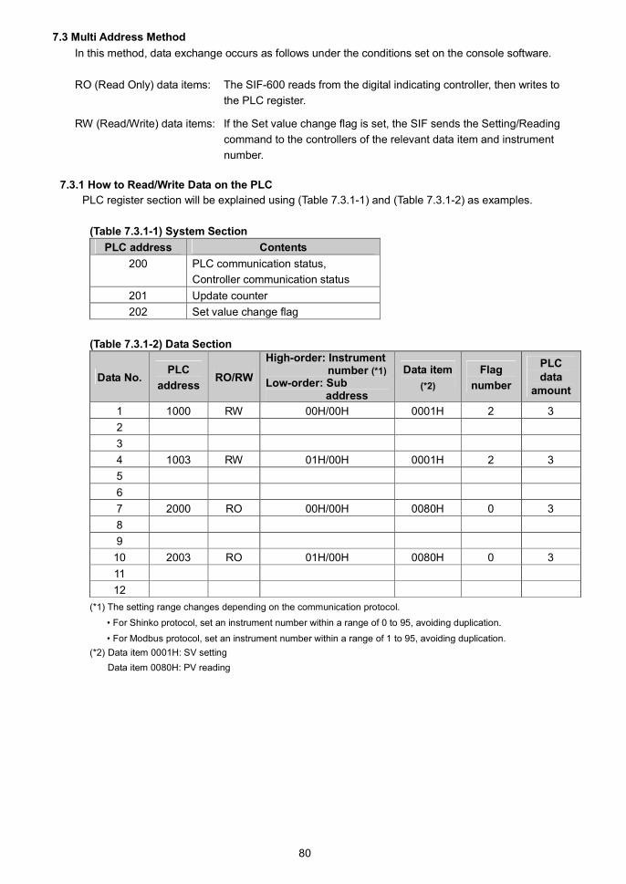
80
7.3 Multi Address Method
In this method, data exchange occurs as follows under the conditions set on the console software.
RO (Read Only) data items: The SIF-600 reads from the digital indicating controller, then writes to
the PLC register.
RW (Read/Write) data items: If the Set value change flag is set, the SIF sends the Setting/Reading
command to the controllers of the relevant data item and instrument
number.
7.3.1 How to Read/Write Data on the PLC
PLC register section will be explained using (Table 7.3.1-1) and (Table 7.3.1-2) as examples.
(Table 7.3.1-1) System Section
PLC address Contents
200 PLC communication status,
Controller communication status
201 Update counter
202 Set value change flag
(Table 7.3.1-2) Data Section
Data No.PLC
addressRO/RW
High-order: Instrumentnumber (*1)
Low-order: Subaddress
Data item
(*2)
Flag
number
PLCdata
amount
1 1000 RW 00H/00H 0001H 2 3
2
3
4 1003 RW 01H/00H 0001H 2 3
5
6
7 2000 RO 00H/00H 0080H 0 3
8
9
10 2003 RO 01H/00H 0080H 0 3
11
12
(*1) The setting range changes depending on the communication protocol.
• For Shinko protocol, set an instrument number within a range of 0 to 95, avoiding duplication.
• For Modbus protocol, set an instrument number within a range of 1 to 95, avoiding duplication.
(*2) Data item 0001H: SV setting
Data item 0080H: PV reading
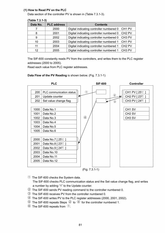
81
(1) How to Read PV on the PLC
Data section of the controller PV is shown in (Table 7.3.1-3).
(Table 7.3.1-3)
Data No. PLC address Contents
7 2000 Digital indicating controller numbered 0 CH1 PV
8 2001 Digital indicating controller numbered 0 CH2 PV
9 2002 Digital indicating controller numbered 0 CH3 PV
10 2003 Digital indicating controller numbered 1 CH1 PV
11 2004 Digital indicating controller numbered 1 CH2 PV
12 2005 Digital indicating controller numbered 1 CH3 PV
The SIF-600 constantly reads PV from the controllers, and writes them to the PLC register
addresses (2000 to 2005).
Read each value from PLC register addresses.
Data Flow of the PV Reading is shown below. (Fig. 7.3.1-1)
PLC SIF-600 Controller
200 PLC communication status CH1 PV [ 25 ]
201 Update counter CH2 PV [ 23 ]
202 Set value change flag CH3 PV [ 24 ]
1000 Data No.1 CH1 SV
1001 Data No.2 CH2 SV
1002 Data No.3 4 CH3 SV
1003 Data No.4
1004 Data No.5
1005 Data No.6
2000 Data No.7 [ 25 ]
2001 Data No.8 [ 23 ]
2002 Data No.9 [ 24 ]
2003 Data No.10
2004 Data No.11
2005 Data No.12
(Fig. 7.3.1-1)
1 The SIF-600 checks the System data.
The SIF-600 checks PLC communication status and the Set value change flag, and writes
a number by adding “1” to the Update counter.2 The SIF-600 sends PV reading command to the controller numbered 0.3 The SIF-600 receives PV from the controller numbered 0.4 The SIF-600 writes PV to the PLC register addresses (2000, 2001, 2002).5 The SIF-600 repeats Steps 2 to 4 for the controller numbered 1.6 The SIF-600 repeats from 1 .
2
3
1

82
(2) How to Write SV on the PLC
Data section of the controller SV is shown in (Table 7.3.1-4).
(Table 7.3.1-4)
Data No. PLC address Contents
1 1000 Digital indicating controller numbered 0 CH1 SV
2 1001 Digital indicating controller numbered 0 CH2 SV
3 1002 Digital indicating controller numbered 0 CH3 SV
4 1003 Digital indicating controller numbered 1 CH1 SV
5 1004 Digital indicating controller numbered 1 CH2 SV
6 1005 Digital indicating controller numbered 1 CH3 SV
The following example shows the controller numbered 0, when changing its SV to 100 .1 Write 100 to the PLC register addresses (1000 to 1002) corresponding to SV of controller
numbered 0.2 Write “2” to the Set value change flag (202).3 Check that Set value change flag (202) is cleared to 0 (zero).
Setting change is now complete.
Attention !
After the set value is changed, check the PLC communication status (200), and see if there is
any error in the setting contents.
If errors have occurred, correct the data and resend it.
Data Flow of the SV Writing is shown in (Fig. 7.3.1-2).
PLC SIF-600 Controller
200 PLC communication status CH1 PV
201 Update counter CH2 PV
202 Set value change flag 3 CH3 PV
1000 Data No.1 [ 100 ] 2 CH1 SV [ 100 ]
1001 Data No.2 [ 100 ] 2 CH2 SV [ 100 ]
1002 Data No.3 [ 100 ] 2 CH3 SV [ 100 ]
1003 Data No.4 [ SV ] 2
1004 Data No.5 [ SV ] 2
1005 Data No.6 [ SV ] 2
2000 Data No.7
2001 Data No.8
2002 Data No.9
2003 Data No.10
2004 Data No.11
2005 Data No.12
(Fig. 7.3.1-2)
6
7
1 4 8
5

83
1 The SIF-600 checks the System data.
The SIF-600 checks PLC communication status and the Set value change flag,
and writes a number by adding “1” to the Update counter.2 On the PLC side, write 100 to the PLC register addresses (1000 to 1002).3 On the PLC side, write “2” to the Set value change flag.4 The SIF-600 checks system data.
Check that the Set value change flag is set to any value except 0.5 The SIF-600 reads data from the PLC register addresses (1000 to 1005).6 The SIF-600 sends SV setting command to controllers numbered 0 and 1.7 The SIF-600 receives response from controllers numbered 0 and 1.8 The SIF-600 checks system data, and clears the Set value change flag to 0.
7.3.2 Action Details and Notes
[Countermeasure when the register data has been cleared]
If register data has been cleared, write “1” to the Set value change flag.
If “1” is written to the Set value change flag, the SIF-600 will read all setting item data from the
controllers, and write it to the PLC register section.
[AT (Auto-tuning)]
When AT is performed, write “1” to the Set value change flag to update all values (proportional band,
integral time, derivative time, ARW) attained from the controller after AT is complete.
If “1” is written to the Set value change flag, the SIF-600 will read all setting item data from the
controllers, and write it to the PLC register section.
[Alarm type]
If the alarm type of the controller is changed, automatically the alarm value of the controller returns
to 0 (zero).
Therefore, be sure to set the alarm value again from the PLC after alarm type is changed.
[Set value change flag]
When setting the Set value change flag, check that it is 0 (zero), then set it to a value.
If the Set value change flag is set to a value while the value is not 0 (zero), setting change may not
be occurred normally.
If “1” is written to the Set value change flag, the SIF-600 reads all setting item data from the
controllers, and writes it to the PLC register section.
[Setting Range of Set Value]
The SIF-600 does not manage the setting range of each setting item of controllers.
When setting any values from the PLC, be sure to set values within the setting range.

84
7.4 Flagless Method
In this method, data exchange occurs as follows under the conditions set via the console software.
The Set value change flag is not used.
RO (Read Only) data items: The SIF-600 constantly reads from the digital indicating controller, then
writes them to the PLC register.
RW (Read/Write) data items: The SIF-600 reads both data from the controller and corresponding data
from the PLC register alternately, and if any change is found, the SIF-600
writes the change to the other side (controller or PLC).
7.4.1 How to Read/Write Data on the PLC
PLC register section will be explained using (Table 7.4.1-1), (Table 7.4.1-2) and (Table 7.4.1-3) as
examples.
(Table 7.4.1-1) System Section
PLC address Contents
200 PLC communication status,
Controller communication status
201 Update counter
202 Communication item change flag
(Table 7.4.1-2) Data Section
Data
No.
PLC
addressRO/RW
PLC address for saving
controller’s instrument number
PLC address for saving
controller’s data item
1 1000 RW 1500 2000
2 1001 RW 1501 2001
3 1002 RW 1502 2002
4 1003 RO 1503 2003
5 1004 RO 1504 2004
6 1005 RO 1505 2005
(Table 7.4.1-3) Data Section and PLC Register Details
PLC address Data Contents
1500 0000H Data No.1 instrument number and sub address (*1)
High-order: Instrument number Low-order: Sub address
1501 0100H Data No.2 instrument number and sub address (*1)
High-order: Instrument number Low-order: Sub address
1502 0200H Data No.3 instrument number and sub address (*1)
High-order: Instrument number Low-order: Sub address
1503 0000H Data No.4 instrument number and sub address (*1)
High-order: Instrument number Low-order: Sub address
1504 0100H Data No.5 instrument number and sub address (*1)
High-order: Instrument number Low-order: Sub address
1505 0200H Data No.6 instrument number and sub address (*1)
High-order: Instrument number Low-order: Sub address
2000 0001H Data No.1 Data item (*2)
2001 0001H Data No.2 Data item (*2)
2002 0001H Data No.3 Data item (*2)
2003 0080H Data No.4 Data item (*2)
2004 0080H Data No.5 Data item (*2)
2005 0080H Data No.6 Data item (*2)
(*1) The setting range changes depending on the communication protocol.
• For Shinko protocol, set an instrument number within a range of 0 to 95, avoiding duplication.
• For Modbus protocol, set an instrument number within a range of 1 to 95, avoiding duplication.
(*2) Data item 0001H: SV setting
Data item 0080H: PV reading

85
(1) How to Read PV on the PLC
Data section of the controller PV is shown in (Table 7.4.1-4).
(Table 7.4.1-4)
Data No. PLC address Contents
4 1003 Digital indicating controller numbered 0 PV
5 1004 Digital indicating controller numbered 1 PV
6 1005 Digital indicating controller numbered 2 PV
The SIF-600 constantly reads PV of controllers, and writes them to the PLC register addresses
(1003, 1004, 1005).
Read each value from PLC register addresses.
Data flow of the PV reading is shown in (Fig. 7.4.1-1).
PLC SIF-600 Controller
200 PLC communication status PV [ 25 ]
201 Update counter
202 Communication item change flag SV
1000 Data No.1
1001 Data No.2
1002 Data No.3
1003 Data No.4 [ 25 ]
1004 Data No.5
1005 Data No.6
1500 Data No.1 Instrument number [0000H]
1501 Data No.2 Instrument number [0100H]
1502 Data No.3 Instrument number [0200H]
1503 Data No.4 Instrument number [0000H]
1504 Data No.5 Instrument number [0100H]
1505 Data No.6 Instrument number [0200H]
2000 Data No.1 Data item [0001H]
2001 Data No.2 Data item [0001H]
2002 Data No.3 Data item [0001H]
2003 Data No.4 Data item [0080H]
2004 Data No.5 Data item [0080H]
2005 Data No.6 Data item [0080H]
(Fig. 7.4.1-1)1 The SIF-600 checks the system data.
The SIF-600 checks PLC communication status and the Set value change flag, and writes
a number by adding “1” to the Update counter.2 The SIF-600 sends the PV reading command to the controller numbered 0, which corresponds
to Data No. 4 (*). (*): PLC register addresses (1003, 1503, 2003)3 The SIF-600 receives the PV from the controller numbered 0.4 The SIF-600 writes the PV to the PLC register address (1003).5 The SIF-600 repeats Steps 2 to 4 for the controllers numbered 1 and 2.6 The SIF-600 repeats from Step 1 .
2
3
1
4

86
(2) How to Update SV on the PLC or Controller
Data section of the controller SV is shown in (Table 7.4.1-5).
(Table 7.4.1-5)
Data No. PLC address Contents
1 1000 Digital indicating controller numbered 0 SV
2 1001 Digital indicating controller numbered 1 SV
3 1002 Digital indicating controller numbered 2 SV
The SIF-600 reads both controller and corresponding PLC register data alternately, and comparestheir values with the internal data of the SIF-600. If there is any change, the SIF-600 changes thecorresponding data (controller or PLC register data).
Usual data flow (when there is no change in SV) is shown in (Fig. 7.4.1-2).
PLC SIF-600 Controller
200 PLC communication status PV
201 Update counter
202 Communication item change flag 100 SV [ 100 ]
1000 Data No.1 [ 100 ]
1001 Data No.2
1002 Data No.3
1003 Data No.4
1004 Data No.5
1005 Data No.6
1500 Data No.1 Instrument number [0000H]
1501 Data No.2 Instrument number [0100H]
1502 Data No.3 Instrument number [0200H]
1503 Data No.4 Instrument number [0000H]
1504 Data No.5 Instrument number [0100H]
1505 Data No.6 Instrument number [0200H]
2000 Data No.1 Data item [0001H]
2001 Data No.2 Data item [0001H]
2002 Data No.3 Data item [0001H]
2003 Data No.4 Data item [0080H]
2004 Data No.5 Data item [0080H]
2005 Data No.6 Data item [0080H]
(Fig. 7.4.1-2)1 The SIF-600 checks the system data.
The SIF-600 checks PLC communication status and Set value change flag, and writes
a number by adding “1” to the Update counter.2 The SIF-600 reads data from the PLC register address (1000: Data No.1).
The SIF-600 compares the SV (100 ) of the PLC register and its own internal value (100 ),
and if there is no change, the SIF-600 does not process anything.3 The SIF-600 sends the SV reading command to the controller numbered 0, corresponding to
Data No.1 (*). (*) PLC register addresses (1000, 1500, 2000)4 The SIF-600 receives SV from the controller numbered 0. The SIF-600 compares the received
SV (100 ) and its own internal value (100 ), and if there is no change, the SIF-600 does not
process anything.5 The SIF-600 repeats Steps 2 to 4 for the controllers numbered 1 and 2.6 The SIF-600 repeats from Step 1 .
3
1
24
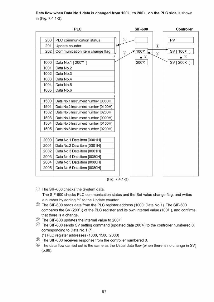
87
Data flow when Data No.1 data is changed from 100 to 200 on the PLC side is shown
in (Fig. 7.4.1-3).
PLC SIF-600 Controller
200 PLC communication status PV
201 Update counter
202 Communication item change flag 100 SV [ 100 ]
1000 Data No.1 [ 200 ] 200 SV [ 200 ]
1001 Data No.2
1002 Data No.3
1003 Data No.4
1004 Data No.5
1005 Data No.6
1500 Data No.1 Instrument number [0000H]
1501 Data No.2 Instrument number [0100H]
1502 Data No.3 Instrument number [0200H]
1503 Data No.4 Instrument number [0000H]
1504 Data No.5 Instrument number [0100H]
1505 Data No.6 Instrument number [0200H]
2000 Data No.1 Data item [0001H]
2001 Data No.2 Data item [0001H]
2002 Data No.3 Data item [0001H]
2003 Data No.4 Data item [0080H]
2004 Data No.5 Data item [0080H]
2005 Data No.6 Data item [0080H]
(Fig. 7.4.1-3)
1 The SIF-600 checks the System data.
The SIF-600 checks PLC communication status and the Set value change flag, and writes
a number by adding “1” to the Update counter.2 The SIF-600 reads data from the PLC register address (1000: Data No.1). The SIF-600
compares the SV (200 ) of the PLC register and its own internal value (100 ), and confirms
that there is a change.3 The SIF-600 updates the internal value to 200 .4 The SIF-600 sends SV setting command (updated data 200 ) to the controller numbered 0,
corresponding to Data No.1 (*).
(*) PLC register addresses (1000, 1500, 2000)5 The SIF-600 receives response from the controller numbered 0.6 The data flow carried out is the same as the Usual data flow (when there is no change in SV)
(p.86).
3
1
2
45
4

88
When SV is changed from 100 to 200 on the controller numbered 0, the data flow is
shown in (Fig. 7.4.1-4).
PLC SIF-600 Controller
200 PLC communication status PV
201 Update counter
202 Communication item change flag 100 SV [ 200 ]
1000 Data No.1 [ 100 ] [ 200 ] 200
1001 Data No.2
1002 Data No.3
1003 Data No.4
1004 Data No.5
1005 Data No.6
1500 Data No.1 Instrument number [0000H]
1501 Data No.2 Instrument number [0100H]
1502 Data No.3 Instrument number [0200H]
1503 Data No.4 Instrument number [0000H]
1504 Data No.5 Instrument number [0100H]
1505 Data No.6 Instrument number [0200H]
2000 Data No.1 Data item [0001H]
2001 Data No.2 Data item [0001H]
2002 Data No.3 Data item [0001H]
2003 Data No.4 Data item [0080H]
2004 Data No.5 Data item [0080H]
2005 Data No.6 Data item [0080H]
(Fig. 7.4.1-4)
1 The SIF-600 checks the system data.
The SIF-600 checks PLC communication status and the Set value change flag, and writes
a number by adding “1” to the Update counter.2 The SIF-600 sends the SV reading command to the controller numbered 0, corresponding
to Data No.1 (*). (*) PLC register addresses (1000, 1500, 2000)3 The SIF-600 receives the SV from the controller numbered 0.
The SIF-600 compares the received SV (200 ) and its own internal value (100 ), and
confirms that there is a change in SV.4 The SIF-600 updates the internal value to 200 .5 The SIF-600 writes the updated data (200 ) to the PLC register address (1000: Data No.1).6 The data flow carried out is the same as the Usual data flow (when there is no change in SV)
(p.86).
4
1
5
2
53
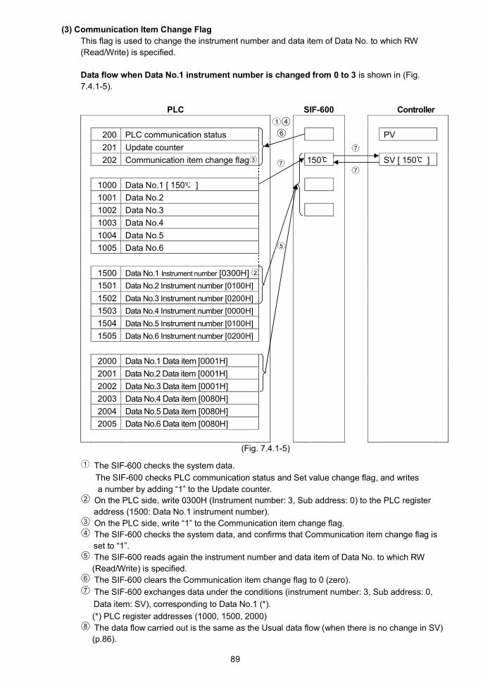
89
(3) Communication Item Change Flag
This flag is used to change the instrument number and data item of Data No. to which RW
(Read/Write) is specified.
Data flow when Data No.1 instrument number is changed from 0 to 3 is shown in (Fig.
7.4.1-5).
PLC SIF-600 Controller
200 PLC communication status PV
201 Update counter
202 Communication item change flag 150 SV [ 150 ]
1000 Data No.1 [ 150 ]
1001 Data No.2
1002 Data No.3
1003 Data No.4
1004 Data No.5
1005 Data No.6
1500 Data No.1 Instrument number [0300H]
1501 Data No.2 Instrument number [0100H]
1502 Data No.3 Instrument number [0200H]
1503 Data No.4 Instrument number [0000H]
1504 Data No.5 Instrument number [0100H]
1505 Data No.6 Instrument number [0200H]
2000 Data No.1 Data item [0001H]
2001 Data No.2 Data item [0001H]
2002 Data No.3 Data item [0001H]
2003 Data No.4 Data item [0080H]
2004 Data No.5 Data item [0080H]
2005 Data No.6 Data item [0080H]
(Fig. 7.4.1-5)
1 The SIF-600 checks the system data.
The SIF-600 checks PLC communication status and Set value change flag, and writes
a number by adding “1” to the Update counter.2 On the PLC side, write 0300H (Instrument number: 3, Sub address: 0) to the PLC register
address (1500: Data No.1 instrument number).3 On the PLC side, write “1” to the Communication item change flag.4 The SIF-600 checks the system data, and confirms that Communication item change flag is
set to “1”.5 The SIF-600 reads again the instrument number and data item of Data No. to which RW
(Read/Write) is specified.6 The SIF-600 clears the Communication item change flag to 0 (zero).7 The SIF-600 exchanges data under the conditions (instrument number: 3, Sub address: 0,
Data item: SV), corresponding to Data No.1 (*).
(*) PLC register addresses (1000, 1500, 2000)8 The data flow carried out is the same as the Usual data flow (when there is no change in SV)
(p.86).
1 4
6
7
7
7
2
3
5

90
Data flow when Data No.1 data item is changed from SV to Alarm 1 value is shown in (Fig.
7.4.1-6).
PLC SIF-600 Controller
200 PLC communication status PV
201 Update counter
202 Communication item change flag 10 SV
1000 Data No.1 [ 10 ] Alarm 1 value
1001 Data No.2 [ 10 ]
1002 Data No.3
1003 Data No.4
1004 Data No.5
1005 Data No.6
1500 Data No.1 Instrument number [0000H]
1501 Data No.2 Instrument number [0100H]
1502 Data No.3 Instrument number [0200H]
1503 Data No.4 Instrument number [0000H]
1504 Data No.5 Instrument number [0100H]
1505 Data No.6 Instrument number [0200H]
2000 Data No.1 Data item [000BH]
2001 Data No.2 Data item [0001H]
2002 Data No.3 Data item [0001H]
2003 Data No.4 Data item [0080H]
2004 Data No.5 Data item [0080H]
2005 Data No.6 Data item [0080H]
(Fig. 7.4.1-6)
1 The SIF-600 checks the system data.
The SIF-600 checks PLC communication status and the Communication item change flag,
and writes a number by adding “1” to the Update counter.2 On the PLC side, write 000BH (Alarm 1 value) to the PLC register address (2000: Data No.1
data item).3 On the PLC side, write “1” to the Communication item change flag.4 The SIF-600 checks the system data.
The SIF-600 checks that the Communication item change flag is set to “1”.5 The SIF-600 reads again the instrument number and data item of Data No. to which RW
(Read/Write) is specified.6 The SIF-600 clears the Communication item change flag to 0 (zero).7 The SIF-600 exchanges data under the conditions (instrument number: 0, Sub address: 0,
Data item: Alarm 1 value), corresponding to Data No.1 (*).
(*) PLC register addresses (1000, 1500, 2000)8 The data flow carried out is the same as the Usual data flow (when there is no change in SV)
(p.86).
1 4
6
5
7
7
2
73

91
7.4.2 Action Details and Notes
[AT (Auto-tuning)]
When AT is performed, the PLC data memory (proportional band, integral time, derivative time, ARW)
is updated, using each value (proportional band, integral time, derivative time, ARW) attained from
the controller after AT is complete.
[Alarm type]
If the alarm type of the controller is changed, automatically the alarm value of the controller returns to
0 (zero).
After the alarm type is changed, be sure to set the alarm value from the PLC again.
[Setting range of set value]
The SIF-600 does not manage the setting range of each setting item of controllers.
When setting any values from the PLC, be sure to set values within the setting range.

92
7.5 Fixed Address Method
In this method, data exchange occurs under the conditions set on the console software as follows.
A maximum of 20 controllers can be connected.
20-Words per data item are occupied in the PLC register section. (The same applies even when less
than 20 controllers are connected.)
RO (Read Only) data items: The SIF-600 constantly reads from the digital indicating controller, and
writes to the PLC register.
RW (Read/Write) data items: If the Set value change flag is set, the SIF sends the setting/reading
command for the predetermined data items to all connected controllers.
7.5.1 How to Read/Write Data on the PLC
PLC register section will be explained using (Table 7.5.1-1) and (Table 7.5.1-2) as examples.
(3 units of controller are connected.)
(Table 7.5.1-1) System Section
PLC address Contents
500 PLC communication status,
Controller communication status
501 Update counter
502 Set value change flag
(Table 7.5.1-2) Data Section
Data
No.PLC address RO/RW Data item
Data
amountFlag number (*3)
1 1000 to 1019 RW 0001 CH1 SV 20 Read: -2/Write: 2
2 1020 to 1039 RW 000B CH1 Alarm 1 value 20 Read: -3/Write: 3
3 1040 to 1059 RW 0002 CH1 AT/Auto-reset
Perform/Cancel
20 Read: -4/Write: 4
4 1060 to 1079 RW 0028 CH1 Control
Allowed/Prohibited
20 Read: -5/Write: 5
5 1080 to 1099 RW 0051 CH2 SV 20 Read: -6/Write: 6
6 1100 to 1119 RW 0071 CH2 Alarm 1 value 20 Read: -7/Write: 7
7 1120 to 1139 RW 0052 CH2 AT/Auto-reset
Perform/Cancel
20 Read: -8/Write: 8
8 1140 to 1159 RW 0078 CH2 Control
Allowed/Prohibited
20 Read: -9/Write: 9
9 1160 to 1179 RO(*1) 0080 CH1 PV reading 20 Read: -10/Write: 10
10 1180 to 1199 RO(*1) 0083 CH1 Status flag
reading
20 Read: -11/Write: 11
11 1200 to 1219 RO(*1) 0090 CH2 PV reading 20 Read: -12/Write: 12
12 1220 to 1239 RO(*1) 0093 CH2 Status flag
reading
20Read: -13/Write: 13
13 1240 to 1259 (*2) (*2) 20 Read: -14/Write: 14
14 1260 to 1279 (*2) (*2) 20 Read: -15/Write: 15

93
Data
No.PLC address RO/RW Data item
Data
amountFlag number (*3)
15 1280 to 1299 (*2) (*2) 20 Read: -16/Write: 16
16 1300 to 1319 (*2) (*2) 20 Read: -17/Write: 17
17 1320 to 1339 (*2) (*2) 20 Read: -18/Write: 18
18 1340 to 1359 (*2) (*2) 20 Read: -19/Write: 19
19 1360 to 1379 (*2) (*2) 20 Read: -20/Write: 20
20 1380 to 1399 (*2) (*2) 20 Read: -21/Write: 21
21 1400 to 1419 (*2) (*2) 20 Read: -22/Write: 22
22 1420 to 1439 (*2) (*2) 20 Read: -23/Write: 23
23 1440 to 1459 (*2) (*2) 20 Read: -24/Write: 24
24 1460 to 1479 (*2) (*2) 20 Read: -25/Write: 25
25 1480 to 1499 (*2) (*2) 20 Read: -26/Write: 26
(*1) Data No. to which RO is specified is Read Only item, and the Set value change flag will be disabled.
(*2) Up to Data No. 25 will be occupied in the PLC register section even if some of them are not used.
20-Words are occupied per data item. (The same applies even when less than 20 units of controller are
connected.)
(*3) On the PLC side, if “1” is written to the Set value change flag, the SIF-600 will read all setting items from
the PLC register section, and sends the setting command to the digital indicating controller.
On the PLC side, if “-1” is written to the Set value change flag, the SIF-600 reads all setting items from the
controller, and writes them to the PLC register.
(1) How to Read PV on the PLC
Data section of the controller PV is shown in (Table 7.5.1-3).
(Table 7.5.1-3)
Data No. PLC address Contents
9 1160 to 1162 Digital indicating controllers numbered 0, 1 and 2 CH1 PV
11 1200 to 1202 Digital indicating controllers numbered 0, 1 and 2 CH2 PV
The SIF-600 constantly reads PV of the controller, and writes them to the PLC register addresses
(1160 to 1162, 1200 to 1202).
Read each value from PLC register.
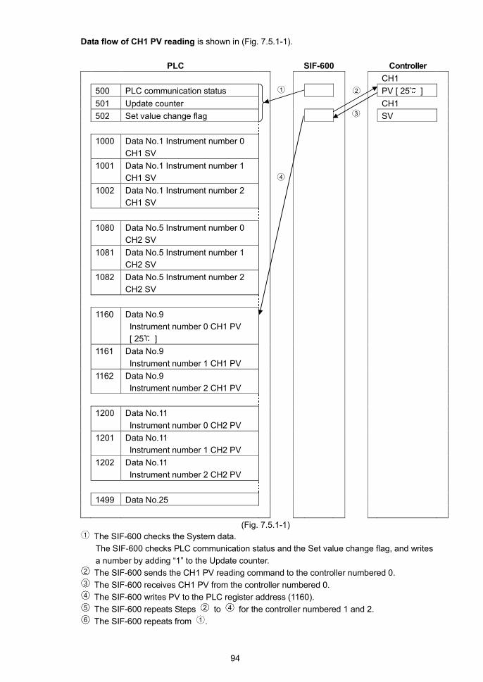
94
Data flow of CH1 PV reading is shown in (Fig. 7.5.1-1).
PLC SIF-600 Controller
CH1
500 PLC communication status PV [ 25 ]
501 Update counter CH1
502 Set value change flag SV
1000 Data No.1 Instrument number 0
CH1 SV
1001 Data No.1 Instrument number 1
CH1 SV
1002 Data No.1 Instrument number 2
CH1 SV
1080 Data No.5 Instrument number 0
CH2 SV
1081 Data No.5 Instrument number 1
CH2 SV
1082 Data No.5 Instrument number 2
CH2 SV
1160 Data No.9
Instrument number 0 CH1 PV
[ 25 ]
1161 Data No.9
Instrument number 1 CH1 PV
1162 Data No.9
Instrument number 2 CH1 PV
1200 Data No.11
Instrument number 0 CH2 PV
1201 Data No.11
Instrument number 1 CH2 PV
1202 Data No.11
Instrument number 2 CH2 PV
1499 Data No.25
(Fig. 7.5.1-1)1 The SIF-600 checks the System data.
The SIF-600 checks PLC communication status and the Set value change flag, and writes
a number by adding “1” to the Update counter.2 The SIF-600 sends the CH1 PV reading command to the controller numbered 0.3 The SIF-600 receives CH1 PV from the controller numbered 0.4 The SIF-600 writes PV to the PLC register address (1160).5 The SIF-600 repeats Steps 2 to 4 for the controller numbered 1 and 2.6 The SIF-600 repeats from 1 .
2
3
4
1

95
(2) How to Write SV on the PLC
Data section of the controller SV is shown in (Table 7.5.1-4).
(Table 7.5.1-4)
Data No. PLC address Contents
1 1000 to 1002 Digital indicating controller numbered 0, 1, 2 CH1 SV
2 1080 to 1082 Digital indicating controller numbered 0, 1, 2 CH2 SV
The following example shows the controller numbered 0, when changing its CH1 SV to 100 .
(Only the controller numbered 0 is changed.)1 Write 100 to the PLC register address (1000) corresponding to CH1 SV of the controller
numbered 0.2 Write “2” to the Set value change flag (502).3 Check that the Set value change flag (502) is cleared to 0 (zero).
Setting changes are now complete.
Attention !
After the set value is changed, check the PLC communication status (500), and see if there is
any error in the setting contents.
If errors have occurred, correct the data and resend it.
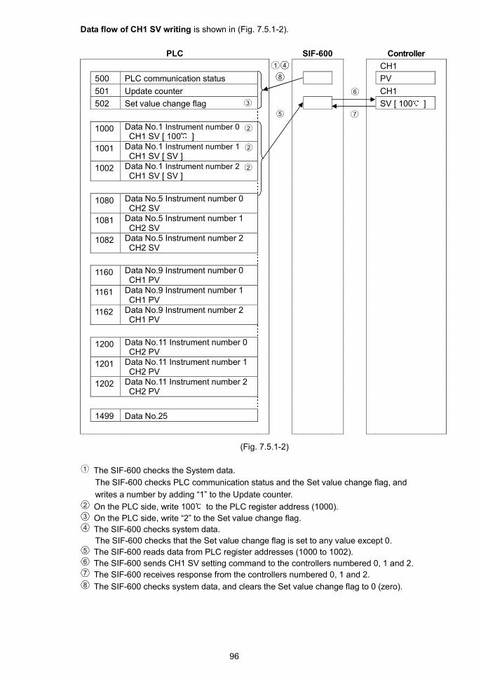
96
Data flow of CH1 SV writing is shown in (Fig. 7.5.1-2).
PLC SIF-600 Controller
CH1
500 PLC communication status PV
501 Update counter CH1
502 Set value change flag SV [ 100 ]
1000 Data No.1 Instrument number 0CH1 SV [ 100 ]
1001 Data No.1 Instrument number 1CH1 SV [ SV ]
1002 Data No.1 Instrument number 2CH1 SV [ SV ]
1080 Data No.5 Instrument number 0CH2 SV
1081 Data No.5 Instrument number 1CH2 SV
1082 Data No.5 Instrument number 2CH2 SV
1160 Data No.9 Instrument number 0CH1 PV
1161 Data No.9 Instrument number 1CH1 PV
1162 Data No.9 Instrument number 2CH1 PV
1200 Data No.11 Instrument number 0CH2 PV
1201 Data No.11 Instrument number 1CH2 PV
1202 Data No.11 Instrument number 2CH2 PV
1499 Data No.25
(Fig. 7.5.1-2)
1 The SIF-600 checks the System data.
The SIF-600 checks PLC communication status and the Set value change flag, and
writes a number by adding “1” to the Update counter.2 On the PLC side, write 100 to the PLC register address (1000).3 On the PLC side, write “2” to the Set value change flag.4 The SIF-600 checks system data.
The SIF-600 checks that the Set value change flag is set to any value except 0.5 The SIF-600 reads data from PLC register addresses (1000 to 1002).6 The SIF-600 sends CH1 SV setting command to the controllers numbered 0, 1 and 2.7 The SIF-600 receives response from the controllers numbered 0, 1 and 2.8 The SIF-600 checks system data, and clears the Set value change flag to 0 (zero).
6
75
1 4
8
2
3
2
2

97
7.5.2 Action Details and Notes
[Countermeasure when the register data has been cleared]
If register data has been cleared, write “-1” to the Set value change flag.
If “-1” is written to the Set value change flag, the SIF-600 will read all setting item data from the
controller, and write it to the PLC register section.
With the Flexible address and Multi address methods, the Set value change flag 1 (positive number)
operates the SIF-600 to read all setting item data from the controller, and to write to the PLC register
section.
Take note that the Set value change flag is a negative number only for the Fixed address method.
[AT (Auto-tuning)]
When AT is performed, write “-1” to the Set value change flag to update all values (proportional band,
integral time, derivative time, ARW) attained from the controller after AT is complete.
If “-1” is written to the Set value change flag, the SIF-600 will read all setting item data from the
controller, and write it to the PLC register section.
[Alarm type]
If the alarm type of the controller is changed, the alarm value of the controller automatically returns
to 0 (zero).
Therefore, be sure to set the alarm value again from the PLC after alarm type is changed.
[Set value change flag]
When setting the Set value change flag, check that it is 0 (zero), then set the flag to any value.
If the Set value change flag is set to a value while the value is not 0 (zero), setting change may not
be occurred normally.
On the PLC side, if “1” is written to the Set value change flag, the SIF-600 will read all setting items
from the PLC register section, and send the setting command to the controller.
On the PLC side, if “-1” is written to the Set value change flag, the SIF-600 will read all setting items
from the controller, and write them to the PLC register section.
[Setting range of set value]
The SIF-600 does not manage the setting range of each setting item of controllers.
When setting any values from the PLC, be sure to set values within the setting range.

98
8. SpecificationsRating
Supply voltage 100 to 240 V AC 50/60 Hz or 24 V AC/DC 50/60 Hz
Allowable fluctuation range:
100 to 240 V AC 50/60 Hz: 85 to 264 V AC
24 V AC/DC 50/60 Hz: 20 to 28 V AC/DC
Communication line
Between SIF and PLC RS-232C, RS-485, RS-422A (terminals)
Between SIF and controller RS-485 (modular jack, terminals)
General Structure
External dimensions 30 x 85 x 110 mm (W x H x D, including socket)
Mounting DIN rail
Case Flame-resistant Color: Light gray
Front panel Membrane sheet
Indicating structure
Displays Upper display and Lower display:
Red LED 4-digit, Character size: 7.4 x 4 mm (H x W)
Status indicator PWR indicator (Yellow):
Lit when power to the SIF-600 is turned ON.
ERR indicator (Red):
Lit when communication errors occur.
PLC indicator (Yellow):
Lit while in Serial communication TX output (transmitting) with the
PLC.
LOC indicator (Yellow):
Lit while in Serial communication TX output (transmitting) with the
digital indicating controllers.
Setting structure Increase Key:
Increases the numeric value, or switches the selection item.
Decrease Key:
Decreases the numeric value, or switches the selection item.
Mode Key:
Selects a setting mode, or registers the set value.
FunctionsController communicationfunction
Communication line RS-485
Communication method Half-duplex communication
Communication speed 9600bps, 19200bps, 38400bps (Default: 9600bps)
Synchronization method Start-stop synchronization
Data format
Start bit 1 bit
Data length 7 bits, 8 bits (Default: 7 bits)
Parity No parity, Even, Odd (Default: Even)
Stop bit 1 bit, 2 bits (Default: 1 bit)
Connectable controllers Controllers with Shinko protocol, Modbus protocol (ASCII, RTU)

99
PLC communication function Communicates with the PLC selected in the Parameter setting mode.
Communication line RS-232C, RS-485, RS-422ARS-422A: Built-in terminator (200 ) between RXA and RXB
Communication method Half-duplex communication
Communication speed 9600bps, 19200bps, 38400bps (Default: 9600bps)
Synchronization method Start-stop synchronization
Data formatStart bit 1 bit
Data length 7 bits, 8 bits (Default: 7 bits)
Parity No parity, Even, Odd (Default: Even)
Stop bit 1 bit, 2 bits (Default: 1 bit)
PLC model Selects a PLC (manufacturer, model) in the Parameter setting mode.
PLC manufacturer Model Register Comm. command
MELSEC D register QR/QWMitsubishi Electric
Corp. MELSEC R register QR/QW
Omron Corp. SYSMAC DM register RD/WR
Keyence Corp. KV DM register RDS/WRSYokogawa ElectricCorp.
FA-M3 D register WRD/WWR
Fuji Electric Co.,Ltd.
MICREX Standardmemory
Loader
Host link unit
PLC manufacturer Model
Mitsubishi Electric
Corp.
AJ71UC24, A1SJ71UC24-R2/R4/PRF
A1SJ71C24-R2/R4/PRF, QJ71C24
Omron Corp. CS1W-SCU21-V1
CJ1W-SCU21, CJ1W-SCU41
Keyence Corp. KV-L20VYokogawa ElectricCorp.
F3LC11-2N, F3LC11-1F, F3LC12-1F
Fuji Electric Co.,Ltd.
NP1L-RS1, NP1L-RS2, NP1L-RS3NP1L-RS4
PLC memory allocation
method PLC memoryallocation
Contents
Flexible address
method
Constantly updates RO (Read Only) data items.
Manages RW (Read/Write) data item settings
with the Set value change flag.
Multi address
method
Block communication command (multiple data
communication command in Modbus protocol)
is available.
Constantly updates RO (Read Only) data items.
Manages RW (Read/Write) data item settings
with the Set value change flag.
Flagless method Constantly updates RO (Read Only) data items.
Manages RW (Read/Write) data item settings
with the Set value change flag.Fixed address
method20 units are fixed in the PLC register section.
Constantly updates RO (Read Only) data items.
Manages RW (Read/Write) data item settings
with the Set value change flag.

100
Powersupply
CPU
Electricallyinsulated
Electricallyinsulated
Communication(LOCAL)
Communication(PLC)
Electricallyinsulated
Setup communication Set up the SIF-600 using the console software, and transmit the
data.
To connect the SIF-600 to a PC, use the USB communication cable
CMB-001, and connect it to the connector on the front panel of the
SIF-600.
OS Windows XP, Windows Vista, Windows 7
Communication line TTL level
Protocol Shinko protocol
Communication method Half-duplex communication
Communication speed 19200bps (Fixed)
Synchronization method Start-stop synchronization
Insulation, Dielectric Strength
Circuit insulation configuration
Insulation resistance 10M or more, at 500V DC
Dielectric strength 1.5kV AC for 1 minutePower terminal – Communication (LOCAL) terminalPower terminal – Communication (PLC) terminalCommunication (PLC) terminal – Communication (LOCAL) terminal
Attached Functions
Display-OFF function By setting the indication time in the Communication mode, displays
are turned off if operation does not take place for the time set in
[Indication time].
If any key is pressed, displays will be turned ON again.
If indication time is set to 0 (zero), continuous indication will occur,
and this function will be disabled.
Auto-light function Automatically measures and controls brightness of the displays and
action indicators.
Other
Power consumption Approx. 7VA
Ambient temperature 0 to 50
Ambient humidity 35 to 85%RH (non-condensing)
Weight Approx.180g (including the socket)
Accessories included Instruction manual 1 copy
Accessories sold separatelyASK-001-1 (Finger-safe, Ring terminals unusable)
SocketASK-002-1 (Ring terminals usable)
Environment specification RoHS directive conformance

101
9. TroubleshootingIf any malfunctions occur, refer to the following items after checking the power is being supplied to the
SIF-600, PLC and Digital indicating controllers.
9.1 Communication
Problem Presumed Cause and Solution
Make sure that the communication connector is securely connected.
Burnout or imperfect contact on the communication cable and the
connector.Securely connect the connector.
Change the cable.
Wiring of the communication cable (connector) is not correct.
Refer to the following sections.
5.4 Connecting to a PLC (Pages 17 to 21)
5.5 Connecting to digital indicating controllers (Pages 22 to 25)
Setup of the SIF-600 is not correct.
Refer to the following sections.
6.2 Setup via console software (Pages 28 to 57)
6.3 Setup in the Parameter setting mode (Pages 58 to 62)
Setup of the PLC (host link unit) is not correct.
Refer to the following section.
6.4 Setup of the PLC (Pages 63 to 72)
Setup of the digital indicating controllers is not correct.
Refer to the following section.
6.5 Setup of digital indicating controllers (p.73)
Communication failure
The instrument numbers of the controllers are duplicated.
Refer to the following section.
6.5 Setup of digital indicating controllers (p.73)
If the Fixed address method is selected in [PLC memory allocation
method] via the console software, the instrument numbers of the
controller should be consecutive from 0 to 19.
9.2 Indication
Problem Presumed Cause and Solution
Displays are unlit. The time set in [Indication time (p.62)] has passed.
If any key is pressed while displays are unlit, they will re-light.
Set the indication time to a suitable time-frame.
Displays are dark. (Enabled) is selected in [Auto-light function (p.62)].
Select (Disabled).
is flashing on the ‘ones’
digit of the Upper display.
Communication errors have occurred while communicating with the
controllers.
Communication error codes are shown below. Check the specifications
of the SIF-600 and controllers based on the error codes indicated on
the ‘ones’ digit of the Lower display.
Communication error codes on the controller side:
Communication error code Contents
Parity error
Negative acknowledgement
Sum error
No response
, : Reserved

102
Problem Presumed Cause and Solution
is flashing on the ‘tens’
digit of the Upper display.
Communication errors have occurred while communicating with the
PLC.
Communication error codes are shown below. Check the specifications
of the SIF-600 and controllers based on the error codes indicated on
the ‘ones’ digit of the Lower display.
Communication error codes on the PLC side:
Communication error code Contents
Parity error
Sum error
No response
, , : Reserved

103
10. Character Table
Upper display Setting item Factory default value Data
PLC memory allocation method
: Flexible address method
: Multi address method
: Flagless method
: Fixed address method
Fixed address method
Controller communication protocol
: Shinko protocol
: Modbus ASCII
: Modbus RTU
Shinko protocol
Controller communication speed
: 9600bps
: 19200bps
: 38400bps
9600bps
Controller data length
: 7 bits
: 8 bits
7 bits
Controller parity
: No parity
: Even
: Odd
Even
Controller stop bit
: 1 bit
: 2 bits
1 bit
PLC model
: Mitsubishi Electric Corp.
MELSEC D register
QR/QW command
: Mitsubishi Electric Corp.
MELSEC R register
QR/QW command
: Omron Corp.
SYSMAC CJ series
: Keyence Corp.
KV
: Yokogawa Electric Corp.
FA-M3
: Fuji Electric Co., Ltd.
MICREX-SX series
Mitsubishi MELSEC
D register QR/QW command
PLC instrument number
0 to 99
0
PLC communication speed
: 9600bps
: 19200bps
: 38400bps
9600bps

Upper display Setting item Factory default value Data
PLC data length
: 7 bits
: 8 bits
7 bits
PLC parity
: No parity
: Even
: Odd
Even
PLC stop bit
: 1 bit
: 2 bits
1 bit
Controller connected units
1 to 20 units
1 unit
Reference address
0000H to FFDCH (0 to 65500)
03E8H (1000)
Auto-light function
: Disabled
: Enabled
Disabled
Indication time
00.00 (Remains lit)
00.01 to 60.00 (Minute.Second)
00.00 (Remains lit)
***** Inquiry *****
For any inquiries about this unit, please contact our agency or the
vendor where you purchased the unit after checking the following.
[Example]
• Model ----------------------------- SIF-600
• Serial number ------------------- No. 11XF05000
In addition to the above, please let us know the details of the
malfunction, if any, and the operating conditions.
SIF61E2 2012.07
SHINKO TECHNOS CO.,LTD.OVERSEAS DIVISION
:Head Office
URL:
E-mail:
2-5-1, Senbahigashi, Minoo, Osaka, Japan
http://www.shinko-technos.co.jp
Tel :
Fax:
81-72-727-6100
81-72-727-7006
Recommended