User guide
PICADOR ®

Table of contents WARNING 1
Read before using 1
WELCOME 2
Foreword 2
PICADOR® documentation 2
PICADOR® Windows 3
Technical support 4 Getting ready for calling technical support 4 How to obtain technical support 4 Remote-Maintenance 4
What you might know before starting the installation 5
Prerequisites 5
Install Picador 6 Installation 6
Uninstall 7
PRESENTATION AND CONVENTIONS 8
Description 8
Mouse conventions 8
The shapes of the pointer of the mouse 9
What we see on the screen PicGEOM ® 10
About ... 11
DRAWING, FILES AND PRINT 12
File Menu 12
Drawings and Files 13 New 13 Open 13 Save As … 13 Save 13 Enregistrer Sous 13 Propriétés 13 Open the file again 14 Import 14 Export 15
Envoyer 15
Output to Plotter 16 Direct Send to Plotter 16 Sortie Traceur Directe 16 HPGL Import Configuration 16 Plotter Configuration 17
Draw and Print 18 Print 18 Layout 18 Print Preview 19
Archiving 20 Goals 20 The research produced a large amount of studies, those -ci are distributed among the different designers. To list all these studies, often using a simple directory. Although this method is a very simple implementation, it has huge drawbacks: risk of forgetting, painstaking research, manual system, non-binding. 20 To overcome these drawbacks, we specified a software module integrated in the range of PICADOR products for building precisely the names of files, archive on the desktop and keep the history of BE studies This module works through the network and is intended to be used by a workgroup. 20 Technical description 20 Archiving and file names 21
Lister les Etudes 21 La case Etude n'est pas cochée 22
OPTIONS : 23 Options 23 Display Options 23 Main Options 23 Catalogues Options 24 Technical Data sheet Options 24 File Options 25 Import / Export Options 25
Zooms 26 Zoom in 26 Zoom out 26 Panoramic Zoom 26 Previous Zoom 26 Zoom Origin 26 Recycle bin 26 Information 26
Filters 27 Deleting filters 27 Deleting all filters 27
Pen configuration 28
Re-draw and re-frame 29
rectangle dimension 29
Formulas 30
Show the number of entities 30
Displaying toolbars and status bar 31
TOOLBARS 32
Display toolbars and the status bar 32
PICK A POINT 33
Entering a point 33 End [ + ] 33 Center / Midlle [ - ] 33 Intersection [ I ] or [ * ] 34 Assistant wizard 35 Details Manual [X] or [Y] 36 On Grid 36
SELECTION 37
Toolbar 37
Near pointer (mouse) 38
Exclusively outside the box 45
Agir sur la sélection 46 Take a copy of the selection. 46 Rotate the selection. 46 Select current mode. 47
LES ATTRIBUTS 48
Attribute definitions 48 Tow type of entity. 48 Group entity. 48 Entity level. 48
Change attributes 49
Change the attributes window 49
Cotation Attributs 50
Text Attributes 51
Change Text Attributes 51
Attributes Hatch. 52
Changing Attributes Hatch. 52
Lock entities 53
Changing 53 Behavior of this function by type of entity: 53
Properties of an entity. 56 Main 56

Lock feature 57 Associations 57
Specialty Tabs 58 Segment Tab 58 Arc tab 59 Text tab 60 CATALOG tab 60 SUB-DESIGN Tab 61
Remove double entities 61 Operating Mode : 61 Principle of the algorithm: 61
Creating a point 61
GEOMETRIC ENTITIES 62
Geometric entities toolbar 62
Entities creations 62 Point 62 The segment by 2 points 63 The broken line 63 Le rectangle 63 Parallelogram 64 Circle 64 The arc by 2 points and a center 65 The arc through 3 points 65 Ellipse 66 The Slot / Handle 67 The chamfer 68 Fillet (rounded) 69
Recovery of deleted entities or all 70
Calculation of center of gravity 70
Refresh 71
DIMENSIONS 72 toolbar 72 Or the keyboard shortcut (Ctrl+U) 72 Dimension between 2 points 72 Dimension between 2 parallel lines 72 The radius Interior 73 Radius Exterior 73 Inside diameter 73 Outside diameter 73 Angle 73 User settings 74
TEXT AND QUESTION 75 Entering Text 75 Entering Questions 75 Texte Avancé 76 Texte Repéré 76 Repeated Text 76

Text Incremented 76
Text Express 77 Enter text Express 77 Setting Texts 77 Replacing Text 77
TECHNICAL DATA-SHEET 78 Insérer une fiche Technique 78 Questionnaire 79 Order Questionnaire 79 Crop Data Sheet 80
INDEED, AFTER THE INSERT SHEET IF YOU CHANGED YOUR PICTURE, AND THAT IT NO LONGER HOLDS IN THE CONTEXT OF TECHNICAL OR TOO SMALL, THIS FUNCTION AUTOMATICALLY REFRAMES THE DATA SHEETCARTON SIZE, WOOD SIZE 80
CARTON SIZE, WOOD SIZE 81
Carton Format 81 Editing, Design 81
Wood wormat 82 Editing, Design 82
CONSTRUCTION 83
Toolbar 83
Clear construction 83
Points 84 Split segment 84
Straight Point (s) 84 Horizontal line. 84 Vertical line. 84 Straight by 2 points. 84 Straight time. 84 Straight parallel point. 85 Right perpendicular point. 85
Right by the right (s) 86 Right distance. 86 Straight oblique. 86 Straight Mediator 86 Rtraight bisector. 86 Straight N - sectrices. 87
The line, circle (s), Straight (s) and point(s) 87 Straight tangent to the circle by 1 point. 87 Straight tangents to a circle and parallel to a straight. 87 Straight tangents to two circles. 87
Circle Point (s) and straight (s) 88 Circle by 1 point and radius, Centre straight. 88 Circle by 2 points and center on the stright. 89 Circle by two points and radius. 89

Circle by three points. 89 Tangent to a circle stright and center. 89 Circle tangent to a straight point and a radius. 90 Circle tangent to two straight and radius. 90 Circle tangent to two lines and 1 point. 90 Circle tangent to 3 lines 90
Circle by circle (s), stright (s) and / or point (s) 91 Circle tangent to a circle and center. 91 Circle tangent to a circle and 2 points. 91 Circle tangent to a circle, a point and radius. 91 Circle tangent to two circles and radius. 92 Circle tangent to two circles and a point. 92 Circle tangent to three circles. 92 Circle tangent to a straight and a circle radius. 93 Circle tangent to a straight, a circle and a point. 93 Circle tangent to a right, a circle center on the stright. 93 Circle tangent to two lines and a circle. 94 Circle tangent to two circles and a stright. 94
LES TRANSFORMATIONS 95
Clear / Gum 96
Remove Window 96
Symmetries 97
Homothety 98
Anamorphosis 99
Translating / Distort 99
Cut / Split 100
Move / Copy 101
Repeat two directions 102
Circular Repeat 102
Rotation 103 Rotation angle 103
Explode Entities 104
PROFILES 105
Creating and deleting a profile. 105 Profil manual 105 Profile interactive manual 105 Contour shifted 106 Select a Profile 106 Profile window 107 Remove profile 107 Area profile 107

THE HATCH 108
Creating and deleting hatching. 108 Crosshatch profile 108 Remove hatching 108 Control of hatching 108
LAYOUT 109
Grouping entities 109
Fitting dynamic 109
Impose 109 Repeat 110 Impose 110 Imbricate 110 Mirror 111
Move Model 112
Explode poses 112
Les informations 113
Data base 114
INSERTING FILES 115
The drawing 115
Les catalogues 116
Images Bimaps 118
THE PARAMETRIC 120
Introduction 120
Utilisation 123 Rating parametric horizontal 123 Rating parametric vertical 123 Rating parametric parallel 124 Rating parametric radius 124 Formulas 125 The arithmetic and trigonometric 126 Pythagore: 126 Create a condition: 126 The parameter definition table: 127 The table is used to declare the creation of parameters, their description information (length, width, height ...) and assign a default. 127 Execute Parametric 127 Clean 127 Generate a parametric component 127 Edit parametric component 127

1
WARNING Read before using
1- THE INFORMATION CONTAINED IN THIS DOCUMENT CAN BE THE SUBJECT
OF MODIFICATIONS WITHOUT NOTICE.
2- THIS DOCUMENT IS GIVEN TO THE READER WITH AN ONLY AIM OF
FACILITATING THE KNOWLEDGE OF THE SYSTEM PICADOR®, OF WHICH IT
ACQUIRED THE RIGHT OF USE.
3- TREEDIM DECLINES ANY RESPONSIBILITY FOR ANY DAMAGE WHICH CAN
RESULT FROM THE INFORMATION CONTAINED IN THIS DOCUMENT.
4- THE ATTENTION OF THE READER IS DRAWN TO THE FACT THAT IT
PROHIBITS TO HIM TO REVEAL, OR TO FACILITATE THE DISCLOSURE OF THIS
DOCUMENT, TO COPY OR REPRODUCE ALL OR PART OF THE DOCUMENT, BY
WHATEVER MEANS OR UNDER WHATEVER FORM THAT IT IS, TO TRANSLATE IT
IN ANY OTHER LANGUAGE, WITHOUT EXPRESS AGREEMENT OF PICADOR

2
Welcome Foreword
Welcome PICADOR® Microsoft Windows, CAD solution that gives you all the power and ergonomics of the most used GUI. Available on all Microsoft Windows platforms, 32-bit & 64 bit (XP, Vista, 7, 8, 10 ...)
PICADOR® documentation
This guide was written for the sake of simplicity and accuracy in the information presented. For each function, you will find a description and the operation step by step implementation.
When that required it, we took care of examples to illustrate the details of the features of PICADOR

3
PICADOR® Windows
PICADOR is a complete suite of CAD software for cardboard packaging design and POS:
• Structural and Parametric Design,
• 3D Folding,
• Assembly product / packaging,
• 3D Animation,
•Technical manual,
• Managing cutting tables for prototype and production
• Standard Libraries (Ecma, Fefco, Plv)
• ERP-CAM Integration (ActiveX, .NET, XML)].
• Optimization of palletization
PICADOR is a native Windows product, designed entirely in object oriented technology (C ++, C #) and uses the Microsoft Class Library (MFC).
PICADOR is a Microsoft solution partner, its software integrates with all Microsoft solutions (Excel, Word, Access, ...) thanks to its technology XDK (ActiveX Development Kit)
The objective is to expand the information system using as database files PICADOR. The sales department will use the fast visualization module in a conversation with a client, the connection to databases, the standard setting (fast obtaining a quote).
Today PICADOR allows you to take advantage of this technology for your Office applications.

4
Technical support
Getting ready for calling technical support
If you need assistance, contact Technical Support PICADOR. Before calling, you put in front of your computer with your drawing to the screen and the user guide of PICADOR at hand. Be ready to provide the following information:
The exact wording of the messages that appeared on your screen when the problem occured.
A description of what happened and what you did at that time.
What was attempted to troubleshoot the problem.
How to obtain technical support
For technical support, please contact the following numbers:
Phone : +33 1 41 42 19 36
Mail: [email protected]
Time of Monday at Friday:
Of 9H00 with 12H00 and 14H00 with 18H00
Remote-Maintenance
If the computer can access the internet, browse the following web site http://www.picador.fr and launch the remote assistance application using the link provided in the homepage.

5
Installation
What you might know before starting the installation
The installation will create a new Windows PICADOR® specific directory: C: \ wpicador.
The executables are located in: C: \ wpicador / bin32
This directory will contain all the modules of the PICADOR® Windows version. To function correctly PICADOR Geometry needs a initialization file: PicGEOM.INI. This file is stored in the C: \ Wpicador \ Bin32. This is an ASCII file, therefore editable, it contains various parameters
The working directory should be: C: \ Picador
Prerequisites Microsoft-Windows Xp, Vista,7, 8, 10 …
CPU 2,5Ghz, RAM 2 Go
6
Install Picador
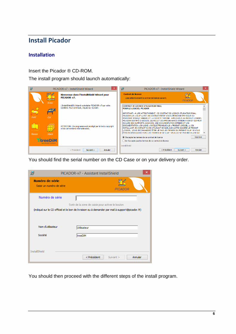
Installation
Insert the Picador ® CD-ROM.
The install program should launch automatically:
You should find the serial number on the CD Case or on your delivery order.
You should then proceed with the different steps of the install program.
7
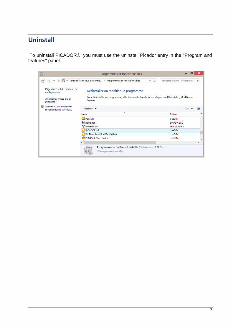
Uninstall
To uninstall PICADOR®, you must use the uninstall Picador entry in the "Program and features" panel.

8
Presentation and conventions Description
PicGEOM © is the main module for 2D design in PICADOR © CAM/CAD suite. It enables the design of 2D geometric shapes using a variety of functions for creation, modification and processing of simple features (segments, arcs, ellipses ..) or complex (profiles, parametric, associated drawings, catalogs, nesting, multi parts ..). This module also allows the covering technical documents: quotation, cross haching, text, data sheets ... He also enjoys all the features of the technology © XDK for setting and imports and exports. With the others modules of PICADOR ©, it is a complete system for design and manufacturing. The modular aspect of PICADOR © allows installing only the modules needed on different workstations
Mouse conventions
The following table explains the basic terms associated with using the mouse.
To Do this
Point or Aim Move the mouse cursor on a face or an object
Click Click the mouse left button and release it
Double-click Quickly press twice the left mouse button and release it
Move Press the left mouse button and keep it pressed while moving the mouse cursor. Then release it.
Right click Click the right mouse button and release it.

9
The shapes of the pointer of the mouse The cursor changes shape according to the task you are performing.
Pointer Site Action
Menus, commands, toolbars To choose commands, to click on an icon or a button.
In the drawing zone. To define a window (selection or zoom) by clicking 2 angles opposed.
On the sides at the top and bottom and corners of the window.
Rollover to resize the window.
In the drawing zone. To produce a back zoom centered on the position of the cursor.
In the drawing zone. Click on an item to select it.
In the drawing zone. Click in the window drawing to select all the elements being under the line of the cursor.
In the drawing zone. Click in the window drawing to select all the elements being with the top of the line of the cursor.
In the drawing zone. Click in the window drawing to select all the elements being on the left of the line of the cursor.
In the drawing zone. Click in the window drawing to select all the elements being on the rigth of the line of the cursor.
In the drawing zone. Define a window by clicking 2 angles opposed to select all the elements included in the window.
In the drawing zone. Click on the screen at the place where you want to position your text.

10
What we see on the screen PicGEOM ® When you run PicGEOM ®, the screen below appears. Identify each part of the display screen PicGEOM ®.
Nota Bene:
* Toolbar stowed: the toolbar can be moved to the graphics area (floating toolbar) or be secured to the edges of the window.
* Each icon is associated with a balloon.

11
About ... This command displays a dialog box containing program information: module name, version, free space on disc, the memory size and the copyright.

12
Drawing, Files and Print File Menu
The management of the drawings documents is done from the FILE menu. From this menu, you can:
create a new drawing
save the drawing in a file,
save the drawing in a catalog,
list the files stored ( option PICSIG ),
open the last backup,
import a drawing from a different file format,
define document properties
plotter output,
plotter configuration,
import configuration,
export a drawing in a different file format,
have a preview of the printer output,
adjust the parameters of the layout and printer,
print the drawing,
send a file through the mail,
reload a past nine designs used by the application,
Quit the application.

13
Drawings and Files
New
Ctrl+N
This command save the drawing displayed (if i twas modified) then initializes the screen to a new document.
Open
Ctrl+O
This command open the dialog box OPEN to browse and select a drawing file (*. des) from the disks. The chosen design is then displayed on the screen.
Save As … This command open the dialog box SAVE As… to browse
and save a drawing in a new file document (*. des).
Save
Ctrl+S
This command save the drawing in the file associated to this document. If the file do not exist, the dialog box SAVE is open to browse and define a new file.
Enregistrer Sous Cette commande affiche la boite de dialogue Enregistrer
Sous afin de sauver le dessin dans un fichier en lui donnant un nom.
Propriétés
The new format allows you to save the file information such as: the name of the company, the author of the design, creation date, modified the last time it was opened, the version number format, comment lines or descriptions. For sub-drawings associated with the document, its properties are accessible using the function double click on the sub-design.

14
Open the file again This new feature allows you to resume work by abandoning all changes made since opening the file. This function is enabled after answering Yes to the next
Import
This command displays the IMPORT dialog box that allows you to select an external drawing file from several types of formats (PDF, EPS, AI, CFF2, DDES, DXF (AutoCAD), HPGL, IGES, N (Diecad. In the dialog box, you can convert the different colors of lines and layers to the Picador type lines. For CNC files (*.cnc) you must choose the post-processors of the CNC Controls.

15
Export
This command displays a dialog box that allows you to EXPORT the drawing in a file to a different type of format (PDF, EPS (Postscript), AI (Adobe Illustrator), CFF2, DDES, DXF (AutoCAD ), HPGL, IGES, N (Diecad), WMF (Windows Metafile)).
Envoyer This command automatically converts the drawing in the desired format and transfer the file in the mail box.

16
Output to Plotter
Direct Send to Plotter Performs an output to an HPGL or HPGL/2 compatible
plotter. A rectangle representing the configuration of the plotter can set the output area.
Sortie Traceur Directe Performs an output to a compatible plotter HPGL or
HPGL/2. The drawing fit in the sheet format automatically.
HPGL Import Configuration Allows you to establish correspondence between the HPGL
pens and the Picador line types.

17
Plotter Configuration
To configure some parameters of the plotter.
Format Define the format limits and the position of the origin of the plotter. For example : for an A4 and an origin in the lower left, the values are : L = 0 B = 0 R = 271.75 T = 190.00 For a centered origin: L = - 135.875 B -95 R= 135.875 T = 95
Buffer and Time On some old plotter with no major internal buffer, it is necessary to "chop" the output block size (Buffer in bytes) and an interval (Time in milliseconds). For plotters that do not require this procedure just put time of 0 milliseconds. The buffer should never be zero.
Port Sets the port (comX:, lptN:) which is connected to the plotter. For ports comX: their configuration is done by the Control Panel of Windows. If no plotter is present, does not put anything in the Port box .
Force HPGL/2 mode Some printers (HP Laser Jet III) accept the language HPGL / 2, but it should be prepared to work in this mode. This check box allows for this preparation.
Scale Change the output scale.
Measurement size Define the size of text in the dimensions.
Pen Allocation Changes the allocation of Picador types lines to HPGL pens.

18
Draw and Print
Ctrl+P
This command will print the image shown on a printer configured in the system.
Layout This command lets you change the layout of the document
and change the header and footer. It should be noted that the font used for the footer is also used for displaying the numbers of entities.
In the header and footer (and in all texts), we can use the system variables:
&d : current date,
&h: current time,
&u: user name (See Preferences on page 37)
&s: name of the company (See Preferences on page 37),
&a: application name and version,
&e: relative scale of the drawing area and the resolution of the printer (this is not exactly the scale of the drawing)
&f: full file name pattern.

19
Print Preview
This command allows the screen to view the layout of the paper document and print it.

20
Archiving
Goals
The research produced a large amount of studies, those -ci are distributed among the different designers. To list all these studies, often using a simple directory. Although this method is a very simple implementation, it has huge drawbacks: risk of forgetting, painstaking research, manual system, non-binding.
To overcome these drawbacks, we specified a software module integrated in the range of PICADOR products for building precisely the names of files, archive on the desktop and keep the history of BE studies This module works through the network and is intended to be used by a workgroup.
Technical description
This module is part of a set of other tools to integrate into a generalized information system (GIS). It dynamically component (DLL) named PicSIG.DLL that can be customized for each company, user group within the same company. The database of archived documents is stored in the file PicSIG.DAT the default directory C: \ Picador. This file is of csv type and can be included in an Excel spreadsheet.
If this DLL is present in the system, the software takes into account PICADOR rout and the archiving procedure in the profile described in the GIS

21
Archiving and file names
To illustrate the operation of the archive and the creation of the file names by the GIS, take for example the case of PicGEOM design module. Suppose a user has designed a study and wishes to save it. In the normal case PicGEOM proposes the following dialog box: While if the archiving module and now we have the following dialogue box: In this case the user must fill in the fields:
Customer,
Ref,
Piece,
Clue, And he will confirm with the Create button. The system will behave in the manner described below.
Lister les Etudes
The box Study is checked
1- In the study directory the system creates if it does not exist the following tree:
The system builds the file name: ET1.des or ET is the prefix for studies and or the following number is automatically assigned by incrementing a current issue.
2- storage history occurs in the PicSIG.DAT file by adding a line describing this operation. This file is editable directly from PicGEOM (Version 1998) thanks to the activation of the Edit menu studies of the File option when PicSIG.DLL is present in the system.

22
La case Etude n'est pas cochée
1- In the study directory (specified in PicGEOM.INI) the system creates if it does not exist the following tree:
The system builds the file name: BR2.des or BR is the prefix for the draft and the following or the number is automatically assigned by incrementing a current issue. 2- storage history occurs in the PicSIG.DAT file by adding a line describing this operation. This file is editable directly from PicGEOM thanks to the activation of the Edit menu studies of the File option when PicSIG.DLL is present in the system. In this case the customer fields, Ref, Piece and index are ignored.

23
Options :
Options The Options tab is use to configure the general environment of Picador.
Display Options The Display tab allows you to: • activate the grid, not in X and Y and the color of the plot (right mouse button). • the background color of the screen. • Activate the origin and the color of the axis (right mouse button). • Change unit of measurement: Inches (inchs) replace the mm. • Change the software language • Change the graphic theme toolbars.
Main Options The General tab lets you define: • the working directory, • the default directory, • automatic backup. • The layout of infinite construction lines or "finished" • A precision pointing value

24
Catalogues Options Ability to configure the display of the grid parts catalogs. (see catalogs or Win V8 format) Ability to define the list of default catalogs.
Technical Data sheet Options Default path to the configuration data sheets. List the data sheets used by default. see Inserting data sheet

25
File Options A recording of a file: - Force V8 formats: can continue to automatically record in V8 format. - Include Sub-Drawings: saves the file all the sub-drawings, parts catalogs and data sheets used in the drawing. - Clean : will launch the function systematically cleaned before each recording. - Delete Entities Doubles: will launch the Delete Entities Double systematically before each recording function.
When opening a file: - Refresh under-drawings: Automatically update the sub-drawings, parts catalogs and technical data sheets. - Ask the Question: The program asks discount for each sub-met drawing. Error messages: When references files are not found, Show or not the error messages with the full path of the non-reference found.
Import / Export Options Establish a connection type: DXF Layers -> Pens Picador Colors DXF -> Pens Picador Explode texts (Picador police) when exporting.

26
View control
Zooms
Zoom in
Shortcut : V
Zoom: enlargement of the area to view. Enter the peaks of two opposite corners of the window to enlarge. The mouse wheel also allows the Zooms.
Zoom out
Shortcut : alt+V
Zoom Out enlargement of the area to be displayed. Enter the center of the new window. The mouse wheel also allows the Zooms.
Panoramic Zoom
Shortcut : alt+P
Panoramic Zoom: moving the area to view it. Enter two points defining the displacement vector of the viewing window. The keyboard arrows also used to move in user space.
Previous Zoom Reframes the drawing on the previous zoom
Zoom Origin Reframes the drawing on the original zoom of the drawing.
Recycle bin
Directly displays the contents of the recycle bin on the screen. Delete an element in the bin to make reappear in the drawing
Information Shortcut : alt+i
Displays the dialog box containing the film, carton size by the number of poses models, etc ...

27
Filters
Displays the Filter dialog box entities this function to filter the display of entities in screen according to several criteria:
Layers : Show (hide) all entities of the selected level.
Groups : Show (hide) all entities of the selected group.
Main : Show (hide) these particular entities.
Pens : Show (hide) all entities using the selected pen.
Entities : Show (hide) the selected entities
For each square, it is possible to reverse the chosen selection. For example, to see only level 2, level 2 select and check the reverse button.
Deleting filters
Supprime tous les filtres posés (sauf ceux des sous-dessins et pièces catalogue) et affiche tout le dessin
Deleting all filters
Removes all installed filters (including those sub-drawings and parts catalog) and displays the entire drawing
28
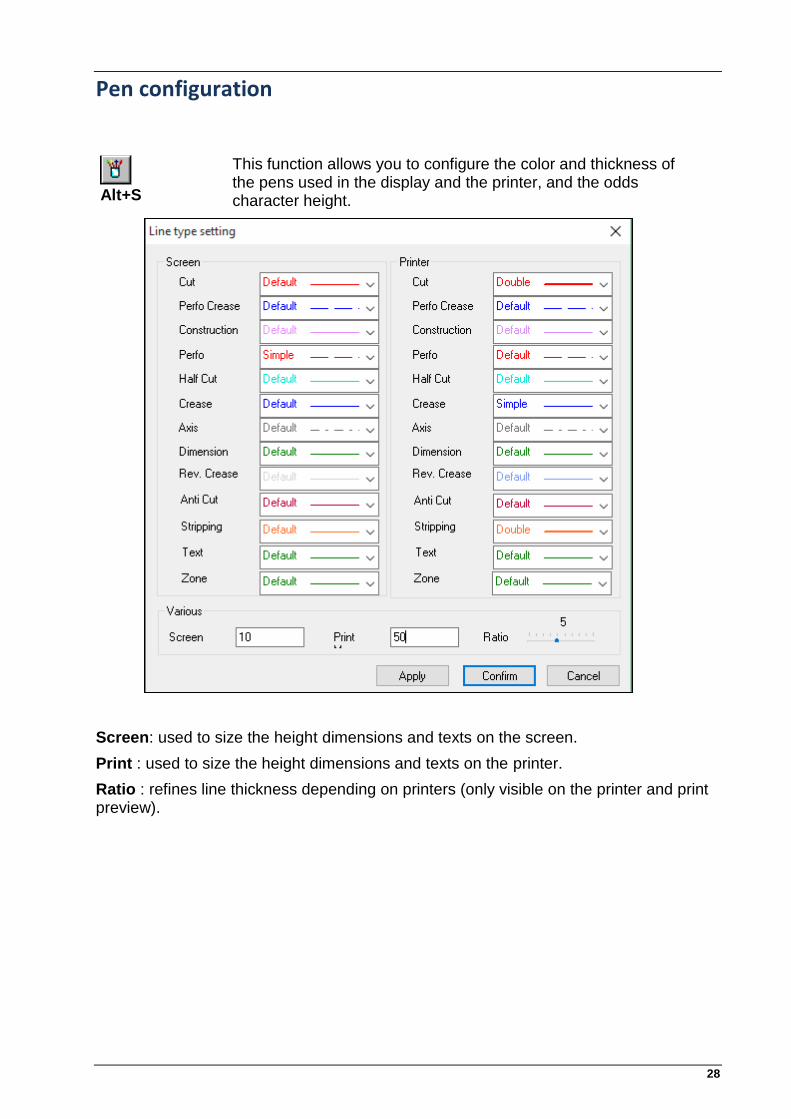
Pen configuration
Alt+S
This function allows you to configure the color and thickness of the pens used in the display and the printer, and the odds character height.
Screen: used to size the height dimensions and texts on the screen.
Print : used to size the height dimensions and texts on the printer.
Ratio : refines line thickness depending on printers (only visible on the printer and print preview).

29
Re-draw and re-frame
R
This function allows re-draw the entire design on the screen.
Z
This function can crop the whole design within the viewing window.
rectangle dimension
This function calculates the overall dimensions of the drawing. This calculation is performed only on the geometric entities (point, segment, arc, ellipse pose in drawing) to the inverse of the crop which it applies on the displayed entities. A color frame (identical to the pen Medium flesh) then regulates the overall format. In the status bar displays the dimensions of the overall size in the form: Rect ExInscrit (X x Y) 272.000 x 299.00

30
Formulas
This function allows you to show or hide the formulas contained in the texts or in the listing. The built-in variables are:
&FmtX = Cardboard format X
&FmtY = Cardboard format Y
&nMod = number of models
&nPos = total number of poses
&Xmin = x minimum geométry
&Ymin = y minimum geométry
&Xmax = x maximum geométry
&Ymax = y maximum geométry
&HtX = x overall geometry
&HtY = y overall geometry
&LgFi = Total rules length
&LgCo = Cut rules length
&LgRa = Crease rules length
&LgPe = Perfo rules length
&LgPr = perfo-crease rules length
&LgMc = half-cut rules length
&LgPt(i) = Rules length per dots
%param% = value of a parameter cotation
&f = file
&d = date
&h = time
&e = scale
&u = user
&s = company
&a = application
Show the number of entities
Alt+L This function allows you to show or hide the numbering entities. The font used for the display is the one used for the footer (see Page Setup Error! Bookmark not defined.)

31
Displaying toolbars and status bar
In the View menu, different options to show or hide toolbars and status bar.
View Menu Options files bar Displays the files toolbar. common attributes bar Displays the common attributes toolbar. Tray bar Displays the status bar when the user messages are
displayed. Toolbars View control Displays the Control toolbar for quick access through
the icons to display different functions:
redesign,
crop,
exinscrit rectangle,
origin,
zoom in,
zoom out,
pan and zoom,
information,
Filters dialog box entities,
Properties dialog box of pens,
dialog control 3D. Selection Displays the toolbar selection allows quick access
through the icons to the various functions of the selection:
Near the mouse pointer,
In the box,
over a horizontal,
below a horizontal,
to the left of a vertical,
the right of a vertical,
properties of the selection. Main Displays the Main toolbar provides quick access to
main functions. Geometry Alt +G
Displays the Geometry toolbar.
Construction Alt+C
Displays the structure toolbar that allows quick access to functions of the buildings.
Transformations Text Ratings Alt+U
Display the toolbar that allows quick access to the listing.
32
ToolBars
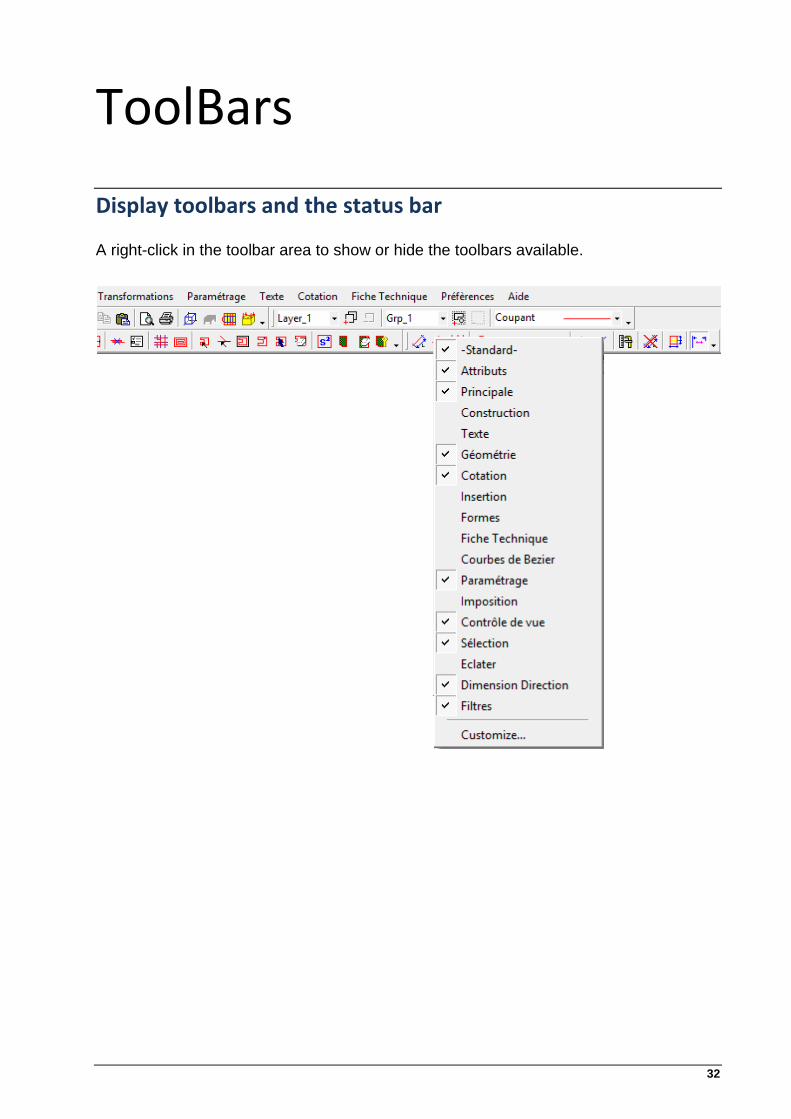
Display toolbars and the status bar A right-click in the toolbar area to show or hide the toolbars available.

33
Pick a point Entering a point
There are several types of seizure of a point (x, y) in the mode near pointer:
the fly ,
In the end,
in the middle,
at the intersection,
manual operation for X & Y,
X or Y manual manual,
on Grid
with the wizard.
The seizure is made on the fly by clicking a point in the drawing area. Other types of seizures are accessible by right mouse button. The initial input type is assigned to the right input at the end. The type of seizure is shown in the status bar) (See page Error! Bookmark not defined)
End [ + ]
To enter a point at the end of an entity, that entity target and press the [+.]. The system then determines the end of the entity closest to the cursor. This input method is then assigned to the mouse Right button, and the status bar indicates EXT. Then just target an entity with the right button to get a point at the end..
Center / Midlle [ - ]
To enter a dot in the center of an entity, that entity target and
press the key [ –.]. The system then determines the middle
point (segment) or center (arc, circle ..) of the entity. This input method is then assigned to the Right mouse button and the status bar indicates MIL. Then just enter an entity with the right button to get a middle point or center.

34
Intersection [ I ] or [ * ]
To enter a point at an intersection entities, press [ I ] or [*]and enter a point near the desired intersection (Fig. 1).
The system then determines the intersection of the entities closest to the target point.
If the two entities are not intersecting the screen, press [ * ] and have the two entities successively (Fig. 2).
The input method is then assigned to the Right mouse button. Then just click the right button of the mouse to aim an intersection of intersecting entities or select one to one intersecting two entities. The status bar indicates INT.
Fig. 1
A
B
A
B A
C
B
Fig. 2

35
Assistant wizard
When typing, a wizard allows you to directly enter one end or the middle of an entity. The cursor changes its appearance depending on the choice possible. To complete the entry with the assistant, just use the right mouse button (the cursor must be that of the wizard).
Extremity Assistant
Middle Assistant .
The wizard configuration is done from the selection dialog.
This dialog box allows you to change: • the selection mode, • the tolerance field and its value, • the maximum number of proposal • manual or automatic validation. • Lock / un-locking the selection wizard
The selection is characterized according to the mode, tolerance, the number of entities and manual or automatic validation.

36
Details Manual [X] or [Y]
To enter coordinates in point a manually, simply press [Y] or [X]. The Following dialog box Appears. Si le clavier dispose d’un pavé numérique, il est possible d’ouvrir le panneau X&Y en utilisant les touches : 0,1,2,3,4,5,6,7,8,9.
Tap successively the values in X and Y coordinates of the point to enter and press the OK button (or hit Enter).
The input values correspond to the point of placement along the axes X and Y.
To enter relative coordinates, simply type the letter r or R before the coordinate value.
On Grid When the grid is displayed, the entry point will be that of the nearest mesh grille. Change the configuration of the grid in the Preferences menu / Options / Display

37
Selection Toolbar
The selection can select one or more entities, including those of a complete drawing in order to modify, obtain information, gather, etc.. . The selection acts on the entity as a toggle: selected / not selected. The selected entities of the design are displayed in white screen. (Or iNotelack if the background is white).
The final selection mode enabled may be reactivated by pressing the [Insert] on your keyboard.
The toolbar offers the following different modes of selection:

38
Near pointer (mouse)
Selecting entities seizures one after the other.
This mode selects one or more entities close to the mouse pointer. This mode is characterized by:
- Tolerance selection is expressed:
Unit is in screen (pixel),
is in units of the drawing scale (real).
- The type of validation caNotee:
Manual,
Automatic (key [ T ] ).
- The number of entities to propose (and type of manual validation)
Example of how it works :
Suppose we want to select an entity near the mouse pointer:
6
1
3
4
2
5
le carré de tolérance de la souris
By type of manual validation with a number of three proposals, the program offers us three options of selection (the entity closest to farthest). Once a selection is validated, the program does more than care proposal and selected as one entity that has been validated.
In this mode, the entities selected are: 1, 2 and 3.
39
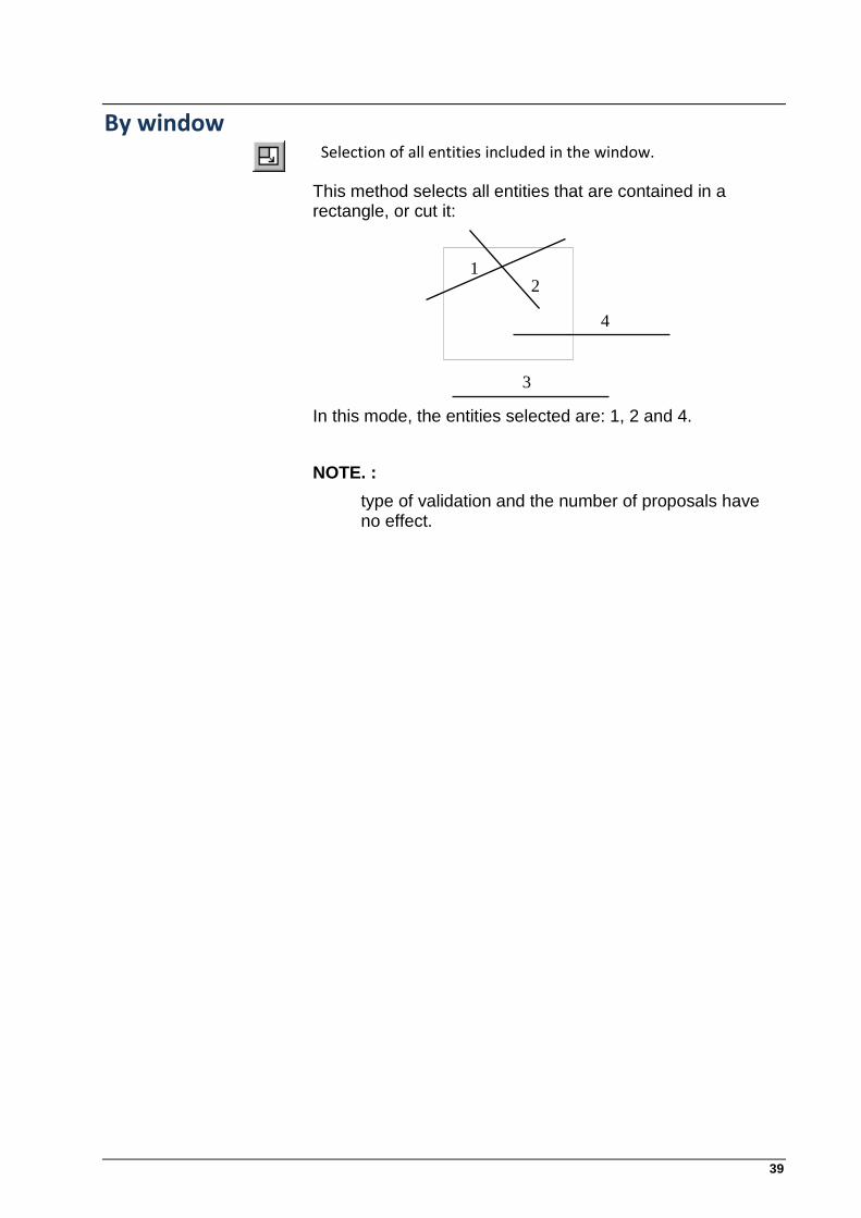
By window
Selection of all entities included in the window.
This method selects all entities that are contained in a rectangle, or cut it:
3
4
12
In this mode, the entities selected are: 1, 2 and 4.
NOTE. :
type of validation and the number of proposals have no effect.

40
Above a horizontal
Selection of all entities at the top compared to the mouse position.
This mode selects all entities located above a horizontal line:
2
1 3
4
Tolérance
Ligne de sélection
5
In this mode, the entities selected are: 1, 2 and 3.
NOTE. :
a) if the tolerance is zero, the entities combined with the selection rectangle are taken into account.
b) the type of validation and the number of proposals have no effect.
c) are taken into account only complete elements (exclusively).

41
Below a horizontal
Selection of all entities at the bottom compared to the mouse position.
This mode selects all entities located below a horizontal line:
2
13
4
Tolérance
Ligne de sélection
5
In this mode, a single entity is selected: 4
NOTE. :
a) if the tolerance is zero, the entities combined with the selection rectangle are taken into account
b) the type of validation and the number of proposals have no effect
c) are taken into account only complete elements (exclusively)

42
To the left of a vertical
Selection of all entities to the left compared to the position of the mouse.
This mode selects all entities located to the left of a vertical line:
1 2
3Tolérance
Ligne de sélection
4
In this mode, a single entity is selected: 1
NOTE. :
a) if the tolerance is zero, the entities combined with the selection rectangle are taken into account
b) the type of validation and the number of proposals have no effect
c) are taken into account only complete elements (exclusively)

43
To the right of a vertical
Selection of all entities located right in relation to the position of the mouse.
This mode selects all entities located to the left of a vertical line:
1 2
3Tolérance
Ligne de sélection
4
In this mode, two entities are selected: 2 and 3
NOTE. :
a) if the tolerance is zero, the entities combined with the selection rectangle are taken into account
b) the type of validation and the number of proposals have no effect
c) are taken into account only complete elements (exclusively)
44
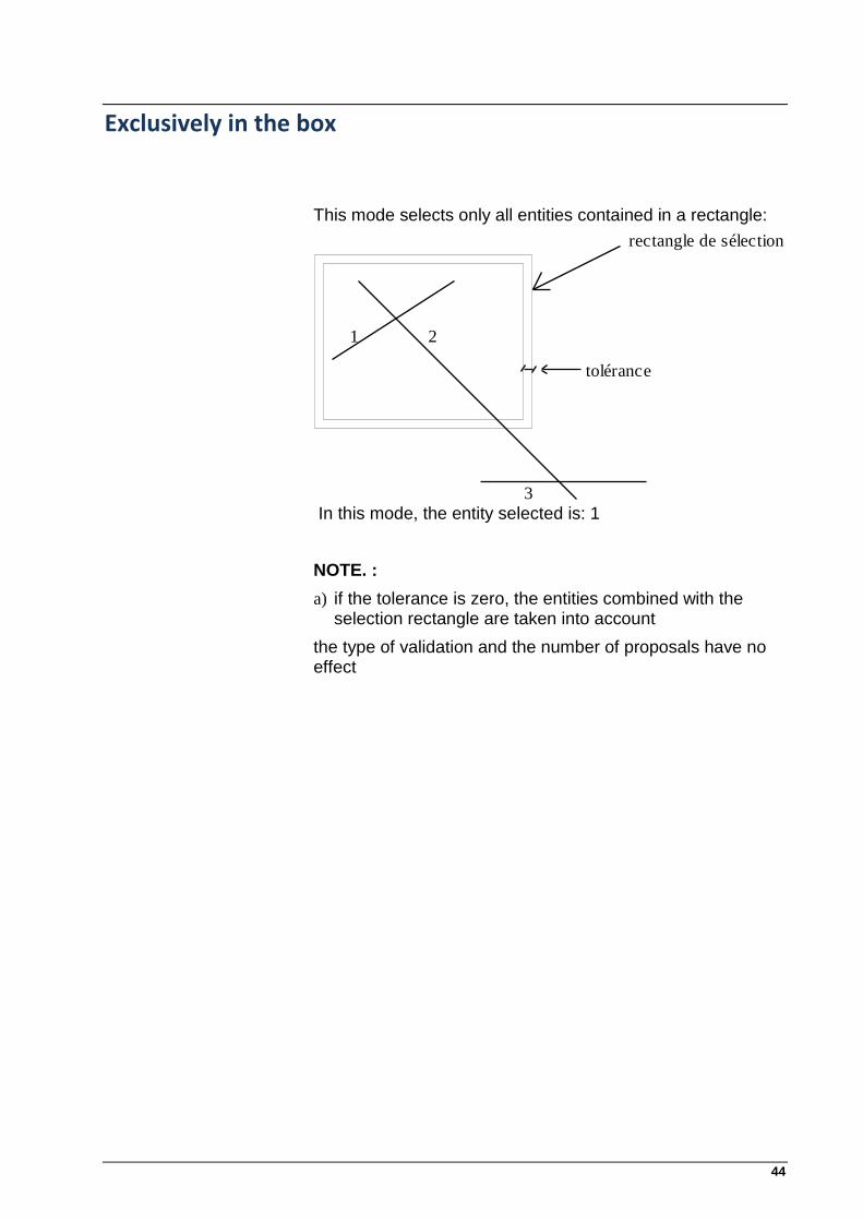
Exclusively in the box
This mode selects only all entities contained in a rectangle:
1 2
3
rectangle de sélection
tolérance
In this mode, the entity selected is: 1
NOTE. :
a) if the tolerance is zero, the entities combined with the selection rectangle are taken into account
the type of validation and the number of proposals have no effect

45
Outside the box This mode selects all the entities that are not contained in a rectangle, or cut it:
1
2
3
In this mode, the entities selected are: 1 and 2
NOTE. :
the type of validation and the number of proposals have no effect
Exclusively outside the box This mode selects all the entities that are not contained in a rectangle:
1
2
3
tolérance
rectangle de sélection
In this mode, a single entity is selected: 2
NOTE. :
a) if the tolerance is zero, the entities combined with the selection rectangle are taken into account
b) the type of validation and the number of proposals have no effect
c)
46
Agir sur la sélection
Take a copy of the selection.
To copy the selected entities when traveling, simply press [Ctrl], it appears in the status bar (see Screen PicGEOM) indicator COPY instead of SHIFT
The [Ctrl] key to toggle the type of press SHIFT,single movement without duplication of the entity.
The selection of entities is maintained until the end of the function Move / Copy ([Esc]). This caNotee repeated quickly several copies of selected entities.
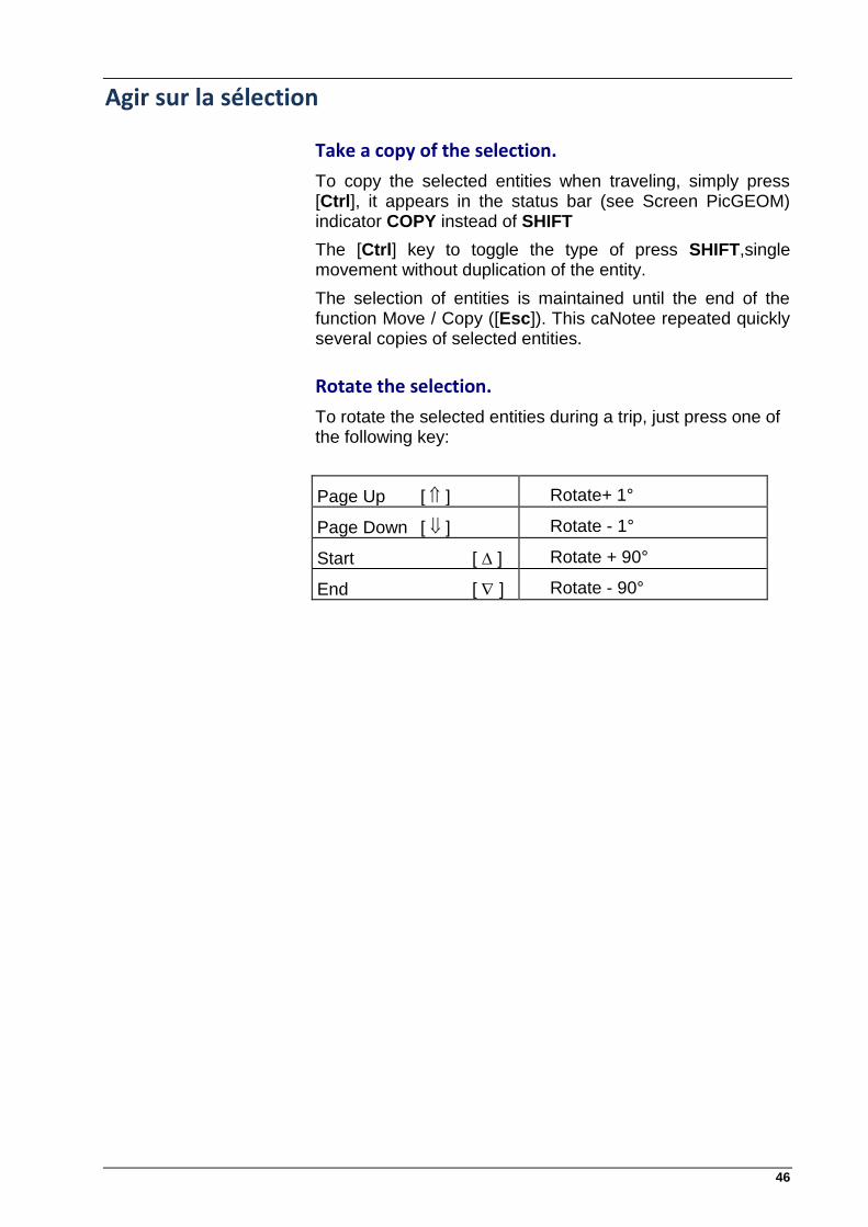
Rotate the selection.
To rotate the selected entities during a trip, just press one of the following key:
Page Up [ ] Rotate+ 1°
Page Down [ ] Rotate - 1°
Start [ ] Rotate + 90°
End [ ] Rotate - 90°

47
Select current mode.
Ins select an entity or group of entities.
Clear the selection.
Ctrl + Ins Unselect all selected entities.
Select All.
Alt + Ins Selects all entities displayed.
Delete selected entities.
Ctrl + Del Removes all entities of the selected database.
If some of these entities are related to profiles, this function automatically clears the link associated with the profiles
Delete an entity
Del Removes the entity pointed to by the mouse. If the entity is linked to profiles, this function automatically deletes the link with the profiles associated.
NOTE. : all entities are erased in the trash and caNotee recovered by removing the trash (See page 27).

48
Les attributs
The attributes are non-geometric parameters that define the function of an entity or a set of entities.
Each entity set inherits attributes or values of currents attributes of the entity from which it came.
The group and the non-visible working player in the attribute bar.
Attribute definitions
Tow type of entity.
The line type is the name of the function of the entity.
It can be either: - Cutting - Perfo-Rain - Construction - Perfo - Half-Cut - Slotting - Axis - Register Mark
Each type of feature can be a different color. (See page 37 pens). The function of each type of stroke is defined by its name: Cutting to the entities using the cutting tool, Construction for the construction entities,
Group entity. The group is an attribute assembly that defines the geometric content (model) of an entity position. It is then possible to compose taxation or amalgams with these poses. It is possible to then compose charges or amalgams with these different position. The Group command allows entities to make this assembly.
Entity level.
The level is an attribute grouping of entities. The entities of the same level can be filtered to display. We can create "layers" of viewing and processing by activating the command filter. Each level is associated with a number of points for the nets.

49
Change attributes This command changes the attributes of entities.
To do this, simply check the attributes to change and set the desired value. After pressing the OK button, each selected entity will take the values of attributes checked.
Change the attributes window This command changes the attributes of entities that we will select from a window. To do this, simply check the attributes to change, defining the desired value, and press the OK button. Then after setting the selection window, each entity included in this window will take the values of attributes ticked.

50
Cotation Attributs
Defining display settings and measurement of an entity rating.
This command displays the following dialog box :
A Area : View document without indicating the value of the rating.
Tolerance: Seizing the gap above and below indicate the value of the symbol.
Text: Enter text that precede or replace the value of the symbol.
Reverse Offset: Reverse the side overhang of the document when it can not be entered between two lines recall odds.
Complementary angle: Choosing the complementary angle to measure a rating corner
Decimal: Set the number of decimals to display rating.
Scale Factor: Set the multiplier of the value of the symbol to display.
Parallel, Vertical, Horizontal: Projection distance between two points to be rated.
Level: Attribute-level listing.
51
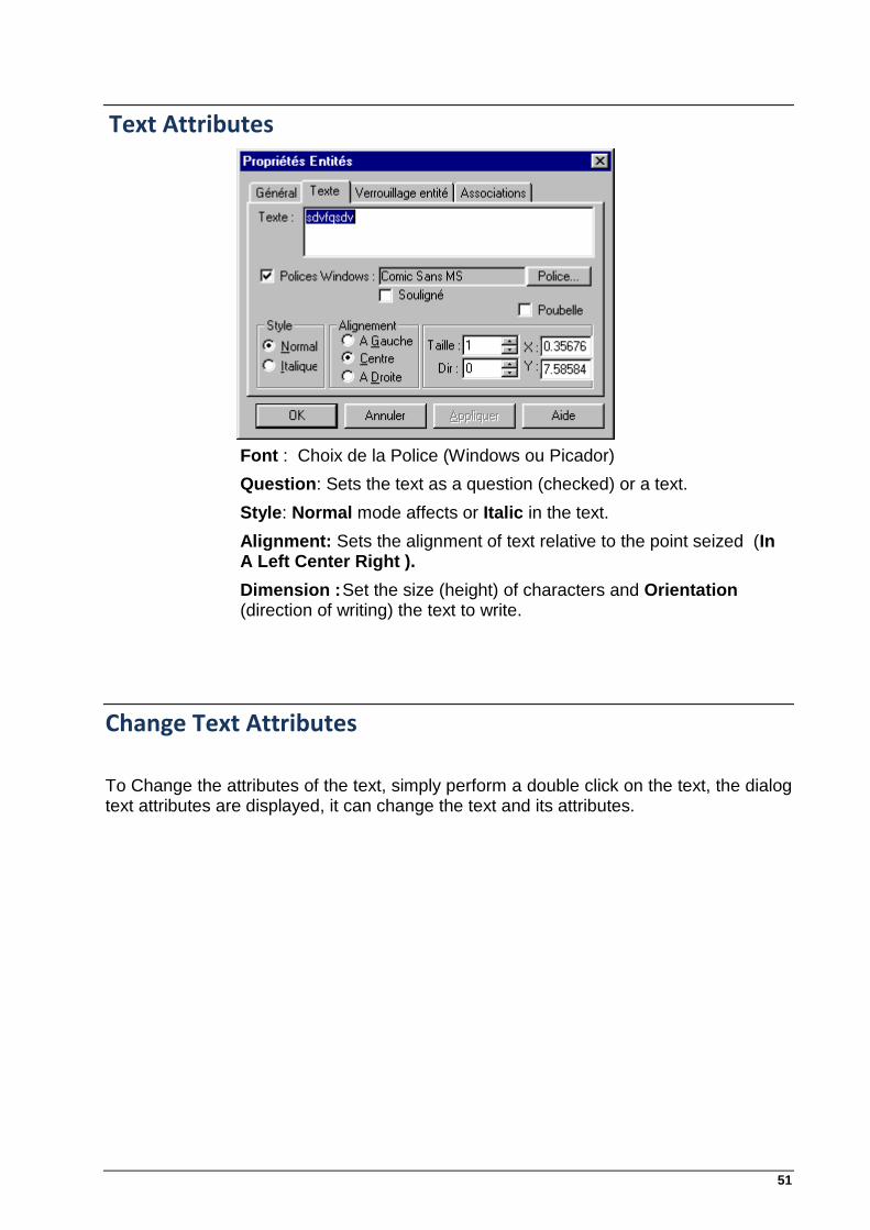
Text Attributes
Font : Choix de la Police (Windows ou Picador)
Question: Sets the text as a question (checked) or a text.
Style: Normal mode affects or Italic in the text.
Alignment: Sets the alignment of text relative to the point seized (In A Left Center Right ).
Dimension : Set the size (height) of characters and Orientation (direction of writing) the text to write.
Change Text Attributes
To Change the attributes of the text, simply perform a double click on the text, the dialog text attributes are displayed, it can change the text and its attributes.

52
Attributes Hatch. This dialog box lets you define the current parameters for the creation of hatching.
Step: define hatching step (distance between two hatches).
Angle : defines the angle of inclination of hatching.
Materials: defines the type of hatching (double lines, single line, a continuous line and a dotted line, etc....).
Changing Attributes Hatch.
In this version, to change the attributes of hatching, use the database.

53
Lock entities
We offer the ability to lock (ie amendment to prohibit) certain characteristic attributes for the entities. The attributes that can be locked depending on the type of entity: Segment: the direction, size, erasing. Arc / Circle: the center, the opening angle, radius, direction. Installation: moving in X and Y, the mirror. Locking the entities combined with functions such as moving or modification gives additional power to control the entity. For example, when one wants to stretch a segment while maintaining its direction, just select it, open the dialog box that locks is then available, check the direction of validating and then using the change function Feature.
Changing This new feature allows you to dynamically change the type entities Segment, Arc or Circle. You can access this function via the menu "Transformations / Edit Entity" or using the icon in the main toolbar.
Behavior of this function by type of entity: Segment: Modify, using the mouse, the end of the segment that was selected, the other end remains fixed.

54
If Dim or Dir are nonzero before the selection:
To change back to using the mouse, you must provide Dim and Dir 0.
Arc : On modify, using the mouse, the end of the arc that has been selected, the other end remains fixed. Circle : On modify, using the mouse, the radius of the circle that has been selected.

55
If Dim is not zero before the selection: To change back to using the mouse, you must return Dim to 0. You can combine this feature with the lock, so resteindre the number of possible changes for a given entity, and to change the radius of an arc without changing its
opening angle, this angle must be locked prior to.

56
Properties of an entity. To edit the properties of an entity, it suffices to perform a double click on the entity (segment, point, arc, ellipse). For each entity type there are three tabs in common: General (can edit / change: the pen, level, groups ...) Lock Feature (allows placing the flags of locks locks for entity FC) Associations (allows you to view the form of a tree all the properties and the list of associations of the entity). For entities segments and arcs, there are special tabs. For the texts of the dialog box to change text remains valid. This new feature will replace the dialog control the database and can modify the attributes of each entity.
Main
The choice of three boxes each containing a list box that can quickly make changes. When a change is made, simply press the Apply button to validate.

57
Lock feature This tab allows you to make / edit the attributes of the lock body. For a detailed description of this tab FC LOCK.
Associations This tab provides an overview of the properties of the entity with the exception of locks. The Value edit box displays the value of the property selected in the tree. If the entity contains a list of associations not empty, we can edit and then obtained a tree identical to:

58
Specialty Tabs For entities like segment or arc there is a special tab.
Segment Tab In this tab, you can edit the parameters of the segment of two ways: given by the size, direction, x, y and by the end E1 (x1, y1) and E2 (x2, y2). Changing the parameters takes into account the possible locks on attributes Segment (Direction, size and delete). The box sends Trash or retrieves the entity in the trash.

59
Arc tab
Changing the settings takes into account the possible locks on the arc attributes (direction, dimension, center angle and delete). The box sends Trash or retrieves the entity in the trash.
60
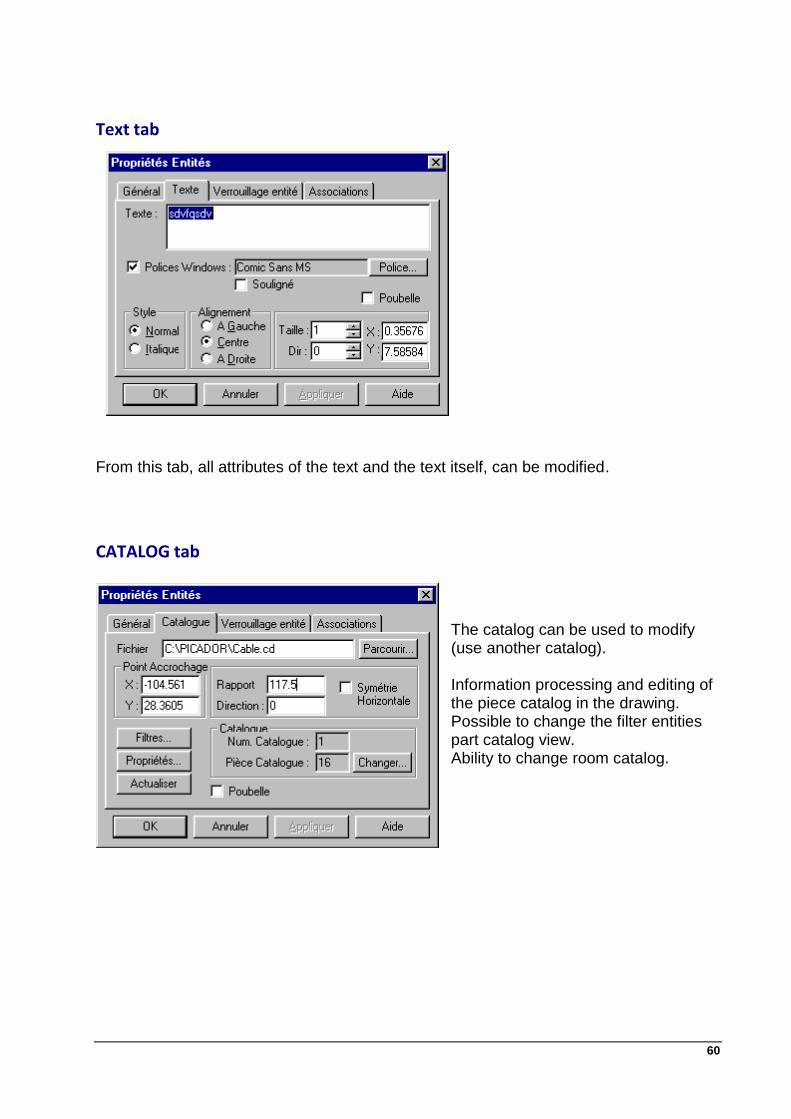
Text tab
From this tab, all attributes of the text and the text itself, can be modified.
CATALOG tab The catalog can be used to modify (use another catalog).
Information processing and editing of the piece catalog in the drawing. Possible to change the filter entities part catalog view. Ability to change room catalog.

61
SUB-DESIGN Tab
The under-drawing can be modified (to use another sub-drawing).
Information processing and modification of sub-drawing in the drawing. Possible to change the filter entities under-drawing to be displayed (eg not to display the listing) Information on the sub-design (see file properties) Update sub-design
Remove double entities This feature allows you to delete all double entities (segments or arcs) included in a drawing Picador.
Operating Mode : If the current selection has more than one entity, the algorithm applies only to the current selection. If the poses are included among these entities selected, they will be ignored. Otherwise, we treat all entities. If the design includes poses, they will all be broken prior.
Principle of the algorithm: If an entity is included in another then this entity is obliterated. If two entities overlap, you scrap one of the two entities so as to eliminate duplication. This feature is available in the menu "Tools / Deletions Double Features" or in the toolbar "Geometry".
Creating a point You can now change the size and angle of a point at its inception in specifying Dim and Dir.

62
Geometric entities Geometric entities toolbar
For all seizures of points, refer - to the chapter on the seizure. For all selections of entities, see the chapter on the selection.
Entities creations
Point
Create with the common attributes a point feature.
Use:
Entrer a point.

63
The segment by 2 points
Create with the common attributes entity segment.
If the value Dim is null:
Enter the 1st point,
Enter the 2nd point.
If the value Dim is not null:
Enter a point,
A Dim segment length and direction Dir is created and displayed from the point defined.
The broken line
Create a common attributes with the continuum of entities segments.
Enter the 1st point,
Enter the 2nd point, The first segment is created between the first 2 points.
Enter the following points. At each point before a segment is created.
Pressing the Esc key on your keyboard to exit the function.
Le rectangle
Créer avec les attributs courants 4 entités segments formant un rectangle .
Enter the 1st point. This is one of the top corner of the rectangle.
Enter the 2nd point. This is then the opposite corner of the previous peak.
Four segments are then created and displayed on the screen.

64
Parallelogram
Create with the common attributes 4 entities segments forming a parallelogram.
Enter the 1st point. This is the apex of one corner of parallelogram.
Enter the 2nd point. This is then the opposite corner of the previous peak.
Enter the 3rd point. This is a 3rd Summit of the parallelogram.
Four segments are then created and displayed on the screen.
Circle
Créer avec les attributs courants une entité cercle.
Enter the 1st point. This is the center of the circle.
If the value Dim is null :
Enter the 2nd point on the circumference of the circle to build.
A circle is created . 2nd through this point.
If the value Dim is not null :
A circle is then created with a radius equal to the value of Dim.

65
The arc by 2 points and a center
Create with the common attributes entity arc.
Enter a 1st point. This is the center of the arc circle.
If the value Dim is null :
Enter a 2nd point on the circumference of the arc to build. This is the departure end of the arc.
Enter a 3rd point on the circumference of the arc to build. This is the other end of the arc.
An arc is created with the end of the last 2 points.
If the value Dim is not null :
The arc of circle radius will build the value of Dim and starting angle value of Dir.
Enter a 2nd point on the circumference of the arc to build. This is the other end of the arc.
The arc through 3 points
Create with the common attributes entity arc.
Enter the 1st point. This is the end of the arc.
Enter the 2nd point on the circumference of the arc to build. This is a crossing point of the arc.
Enter the 3rd point. This is the other end of the arc.
An arc through the three points is then created.
66
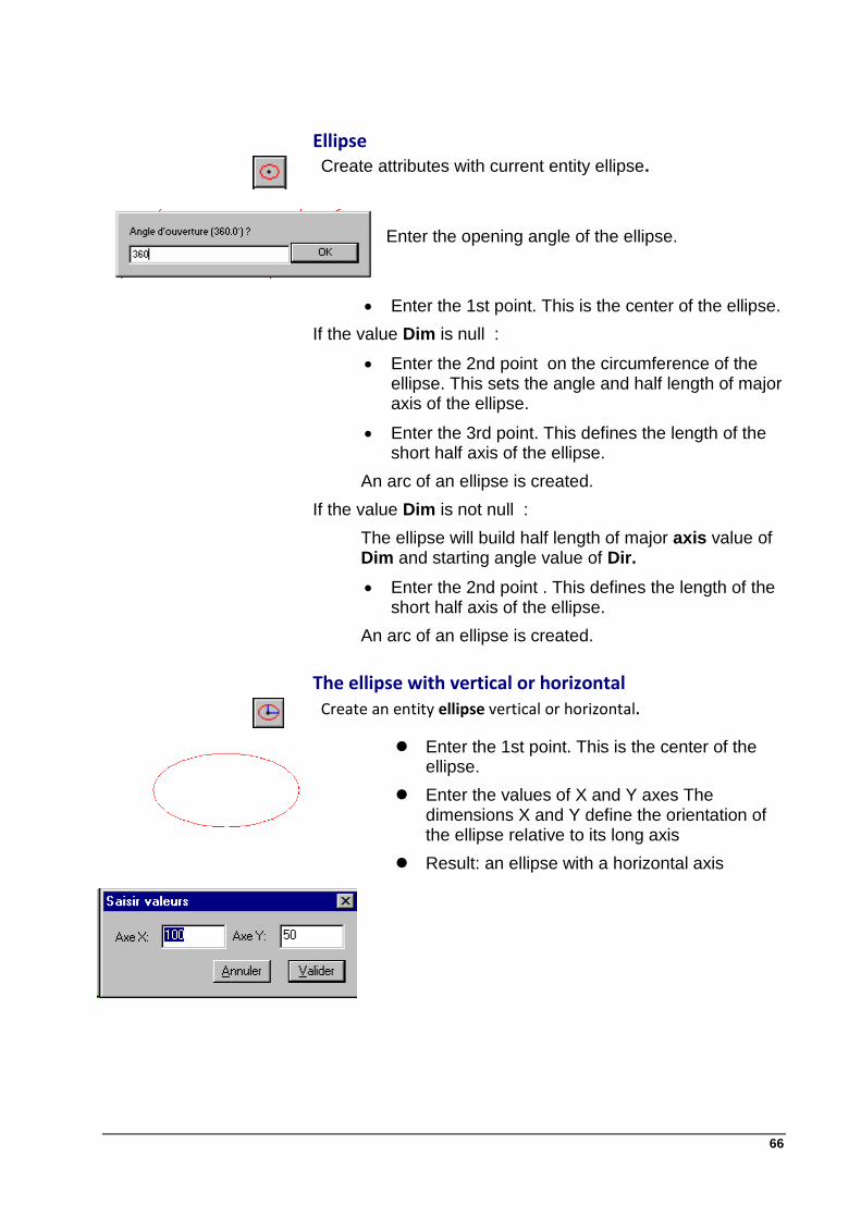
Ellipse
Create attributes with current entity ellipse.
Enter the opening angle of the ellipse.
Enter the 1st point. This is the center of the ellipse.
If the value Dim is null :
Enter the 2nd point on the circumference of the ellipse. This sets the angle and half length of major axis of the ellipse.
Enter the 3rd point. This defines the length of the short half axis of the ellipse.
An arc of an ellipse is created.
If the value Dim is not null :
The ellipse will build half length of major axis value of Dim and starting angle value of Dir.
Enter the 2nd point . This defines the length of the short half axis of the ellipse.
An arc of an ellipse is created.
The ellipse with vertical or horizontal
Create an entity ellipse vertical or horizontal.
Enter the 1st point. This is the center of the ellipse.
Enter the values of X and Y axes The dimensions X and Y define the orientation of the ellipse relative to its long axis
Result: an ellipse with a horizontal axis

67
The Slot / Handle
Create with the common attributes of an oblong hole formed two entities segments and arcs of two entities.
If the value Dim is null :
Enter the length of the slot.
If the value Dim is not null :
The slot will pitch the value of Dim
In cases 2 the slot will be towards the value Dir
Enter the height of the oblong hole
Enter the point of attachment of the slot
An oblong consists of two segments and two arcs are created.
Press [Esc] key to exit the function.

68
The chamfer
Create a segment with inherited attributes of two sides and truncate these two sides
Select a first right. The first right is the right reference.
Select a 2nd straight
If the value Dim is null :
Enter the length Chamfering
If the value Dir is null:
Enter the chamfer angle relative to the reference line
The chamfer is created with a new segment and the two other sides truncated.
If both entities have a starting or associations in common, the new entity (3) making up the groove, inherited or associations (eg association with a profile).
5 Dim
20° Anlgle
1
2
3
1
2
69
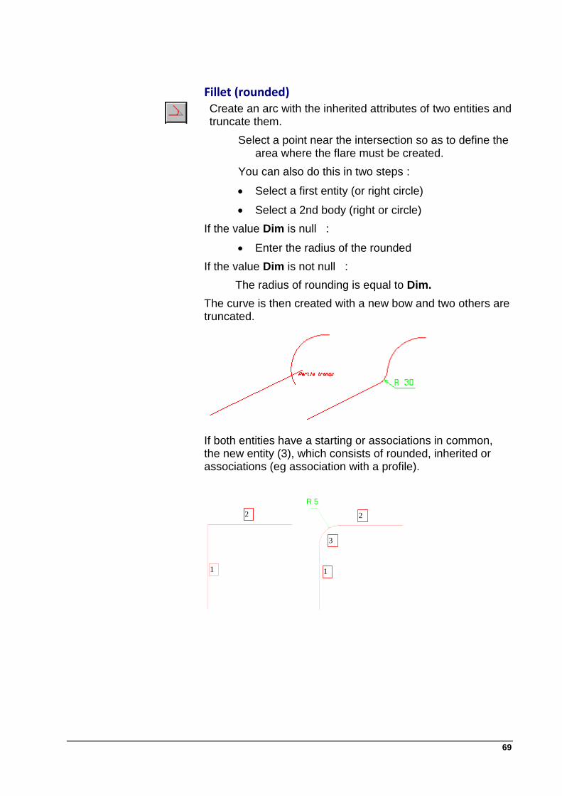
Fillet (rounded)
Create an arc with the inherited attributes of two entities and truncate them.
Select a point near the intersection so as to define the area where the flare must be created.
You can also do this in two steps :
Select a first entity (or right circle)
Select a 2nd body (right or circle)
If the value Dim is null :
Enter the radius of the rounded
If the value Dim is not null :
The radius of rounding is equal to Dim.
The curve is then created with a new bow and two others are truncated.
If both entities have a starting or associations in common, the new entity (3), which consists of rounded, inherited or associations (eg association with a profile).
R 5
1
2
3
1
2

70
Recovery of deleted entities or all
Ctrl+Z
PicGEOM offers the possibility to recover the last deleted entities in various operations (delete, burst, translatable deformed, etc ....)
Alt+R
Total restoration of drawing from the last backup automatically or manually. If the user has performed a manual backup (key S) and if there is an automatic backup of the design choices of food is offered to the user :
Otherwise the system does catering as there is no backup (the icon is grayed out) or he uses the last valid
Calculation of center of gravity In the Tools menu option center of gravity creates a dot in the center of gravity of a selection of entities provided that it forms a convex set if this point has no meaning

71
Refresh
This feature allows you to update a file reference inserted in the drawing run (under-drawing, catalog, data sheet). This option can be automated with the menu Preferences -> Options -> Files .

72
Dimensions toolbar
The menu listing can be enabled by the command:
View -> Toolbars -> Trading
Or the keyboard shortcut (Ctrl+U)
Dimension between 2 points Create an entity rated distance with common attributes
Enter the 1st point,
Enter the 2nd point ,
Enter the 3rd point for place the document.
(See Listing Attributes on page 135 for the different projections and displays the value rating.)
Dimension between 2 parallel lines
Create an entity rated distance with common attributes
Select a 1st line,
Select 2nd line ,
Enter the point for place the document.

73
The radius Interior
Create an entity inside radius with common attributes.
Select a circle or an arc,
Enter a point to guide the rating.
Radius Exterior
Create an entity outside radius with common attributes
Select a circle or an arc.
Enter a point to guide the rating.
Inside diameter
Create an entity with the inner diameter common attributes
Select a circle or an arc.
Enter a point to guide the rating
Outside diameter
Create an entity outside diameter with common attributes
Select a circle or an arc.
Enter a point to guide the rating.
Angle
Create an entity rating corner with common attributes
Select a first segment.
Select a 2nd segment.
Enter a point to position the document.

74
User settings Create an entity rated by associating a user setting
We must create a document using the parameters A Space and Text box configuration of the quotation, the name of the parameter must be framed by two symbols %.

75
Text and Question
Entering Text
Create a text entity with common attributes and attributes of text
Enter the text to write in the dialog box
Select the font you want (Windows or Picador)
Select the desired attributes (style, alignment)
Select the size and orientation of the text
On Line: This option allows you to position and orient a text to an existing line. If this box is checked, the sytem will be asked to select a straight forward position and orient the text to the desired distance.
Entering Questions
Question: If the box is checked, the text will be created from a field survey. The current document is a data sheet.(See Technical Questionnaire)
Default value: Sets the default value to assign to the matter at the creation of the sheet. This value can always be kept where only used when creating. The default may be a field or a user setting.
Save: Allows you to keep the default and assess each display.
76
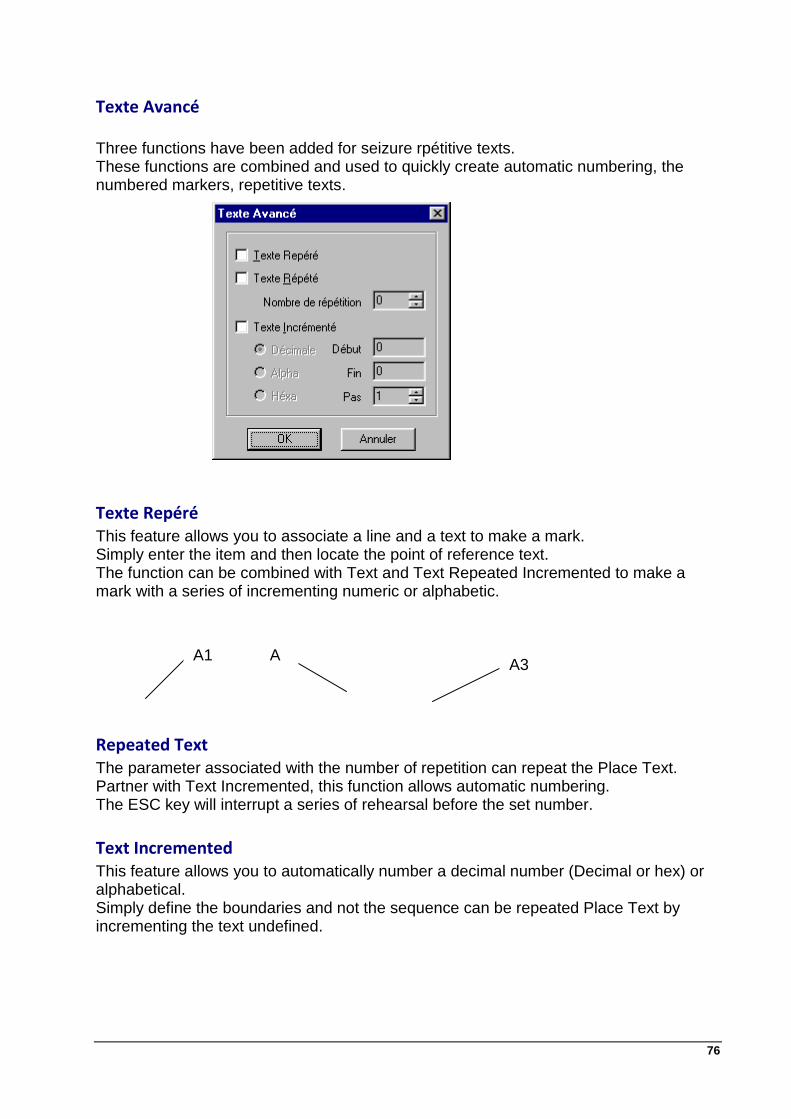
Texte Avancé Three functions have been added for seizure rpétitive texts. These functions are combined and used to quickly create automatic numbering, the numbered markers, repetitive texts.
Texte Repéré This feature allows you to associate a line and a text to make a mark. Simply enter the item and then locate the point of reference text. The function can be combined with Text and Text Repeated Incremented to make a mark with a series of incrementing numeric or alphabetic.
Repeated Text The parameter associated with the number of repetition can repeat the Place Text. Partner with Text Incremented, this function allows automatic numbering. The ESC key will interrupt a series of rehearsal before the set number.
Text Incremented This feature allows you to automatically number a decimal number (Decimal or hex) or alphabetical. Simply define the boundaries and not the sequence can be repeated Place Text by incrementing the text undefined.
A1 A2
A3

77
Text Express
Enter text Express
Cette nouvelle fonction dans la barre d'outils principale permet de saisir directement à l'écran un texte à la position et à la taille choisie. L'affichage se fait dynamiquement au moment de la frappe. This function is controlled by the command Setup text or by the parameters of the dialog box texts.
Setting Texts
This box lets you define default settings for text input.
Replacing Text
The next dialog box allows you to replace a text by another case-sensitive (upper / lower) if you want.

78
Technical data-sheet
The term sheet covers the technical concept Picador cartridge and Fond Plan. A sheet is a design standard that includes Picador an additional questionnaire and a useful area.
In the toolbar and menu are grouped all functions related to the use of the data sheet and questionnaire: - Insert a Sheet. (See Insert a sheet). - Delete Sheet. - Crop a Technical. - Filter a Data Sheet. (Technical Shown / Hidden) - Call the Questionnaire. - Reorder the Questionnaire. (See Questionnaire Order) - Create a Useful Area.
Insérer une fiche Technique
The Specifications are those contained in proposed in the list. This list may be supplemented or amended according to the Preferences -> Options -> Specs This feature allows you to automatically insert the sheet in the current document. (Cropping automatic sheet around the design) and complete the questionnaire (carton).

79
Questionnaire
Each sheet is associated with a questionnaire (cartridge). The questionnaire function allows any time to enter and edit the fields in the questionnaires.
To create a questionnaire in a sheet, simply create texts by notching the option question.
(See text function)
Order Questionnaire
This feature allows you to direct questions at the call of the questionnaire. By default, questions are displayed in order of creation.

80
Useful Area
To facilitate use of fact sheets, there is an entity Useful Area to include only one model of technical and determines the area to contain the design data sheet:
Figure 1 : Surface useful in a model of technical.
When drawing from a model of inserting a sheet with a floor space, the model sheet is automatically sizes so that the area of floor space to contain the entire design which he remains on the scale 1.
Crop Data Sheet This function is used to crop a crop at any time and automatically Sheet. Indeed, after the insert sheet if you changed your picture, and that it no longer holds in the context of technical or too small, this function automatically reframes the data sheet
81
Carton size, Wood size
Carton Format
Editing, Design
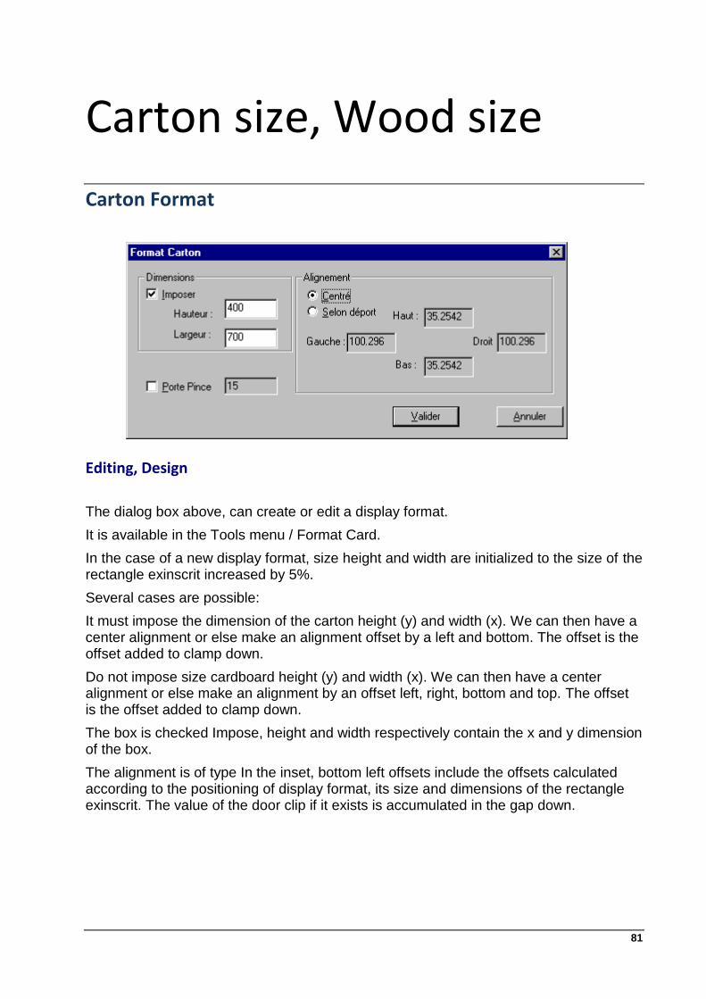
The dialog box above, can create or edit a display format.
It is available in the Tools menu / Format Card.
In the case of a new display format, size height and width are initialized to the size of the rectangle exinscrit increased by 5%.
Several cases are possible:
It must impose the dimension of the carton height (y) and width (x). We can then have a center alignment or else make an alignment offset by a left and bottom. The offset is the offset added to clamp down.
Do not impose size cardboard height (y) and width (x). We can then have a center alignment or else make an alignment by an offset left, right, bottom and top. The offset is the offset added to clamp down.
The box is checked Impose, height and width respectively contain the x and y dimension of the box.
The alignment is of type In the inset, bottom left offsets include the offsets calculated according to the positioning of display format, its size and dimensions of the rectangle exinscrit. The value of the door clip if it exists is accumulated in the gap down.

82
Wood wormat
Editing, Design
The dialog box above, can create or edit an existing timber format. It is available in the Tools menu / Format Woods.
The behavior of the timber format is identical to that of display format.
Compatibility
PicGeom is compatible with Picador V8, meaning it can read any drawing containing a format timber from Picador Packaging, the converse is false.
The format timber is represented on the screen as follows:

83
Construction
This module allows PICADOR produce all types of construction from straight lines, circles, dots and geometric constraints (parallel, tangent, perpendicular).
These buildings are made using the attribute Pen: Construction. These entities are circles or straight lines on which we can support the drawing entities to achieve.
These constructs can be either filtered display, or be removed by the Delete function construction (See Clear construction).
Toolbar
To display the toolbar construction click
View -> Toolbars -> Construction
Clear construction
Deletes all entities of the construction drawing.
This command removes all the drawing entities with attribute pen is built.
The entities can be retrieved by the function Bin Order Filter (See Filter).
84
Points
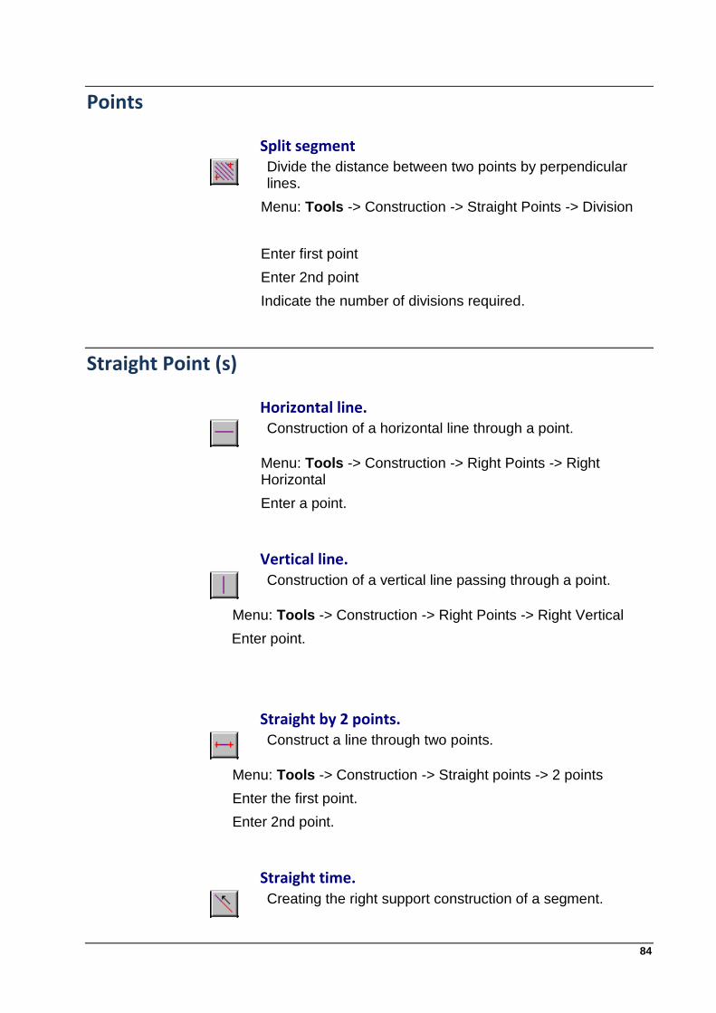
Split segment
Divide the distance between two points by perpendicular lines.
Menu: Tools -> Construction -> Straight Points -> Division
Enter first point
Enter 2nd point
Indicate the number of divisions required.
Straight Point (s)
Horizontal line.
Construction of a horizontal line through a point.
Menu: Tools -> Construction -> Right Points -> Right Horizontal
Enter a point.
Vertical line.
Construction of a vertical line passing through a point.
Menu: Tools -> Construction -> Right Points -> Right Vertical
Enter point.
Straight by 2 points.
Construct a line through two points.
Menu: Tools -> Construction -> Straight points -> 2 points
Enter the first point.
Enter 2nd point.
Straight time.
Creating the right support construction of a segment.

85
Menu: Tools -> Construction -> Straight Points -> Extension Select the segment to extend
Straight parallel point.
Construct a line parallel to another line and passing through a point.
Menu: Tools -> Construction -> Straight Straight -> Parallel by 1 point
Select a straight
Enter a point.
Right perpendicular point.
Construct a line perpendicular to another line and passing through a point.
Menu: Tools -> Construction -> Straight Straight -> Orthogonal
Select a straight
Enter point.

86
Right by the right (s)
Right distance.
Build one (or two) straight (s) parallel (s) another straight and a given distance.
Menu: Tools -> Construction -> Straight Straight -> Orthogonal
Select a Straight
Enter the value of distance in the dialog box,
Choose the right (or 2 lines).
Straight oblique.
Build one (or two) straight (s) oblique (s) to another right a given angle and passing through a point.
Menu: Tools -> Construction -> Straight Straight -> Oblique
Select a straight
Enter a point.
Enter the value of the angle in the dialog box
(Trig or inverse trig sense).
Choose the right (or 2 lines).
Straight Mediator
Building the right bisector of a segment.
Menu: Tools -> Construction -> Straight Straight -> Mediatrix
Select a line.
Rtraight bisector.
Build one (or two) right (s) bisector (s) of 2 intersecting lines.
Menu: Tools -> Construction -> Straight Straight -> Bisector
Select the first straight
Select a 2nd straight
Choose the right (or 2 lines).

87
Straight N - sectrices.
Build n right n sectors 2 defining intersecting lines.
Menu: Tools -> Construction -> Straight Straight -> N-Sectrices
Select the first right
Select a 2nd straight
Enter the number of divisions in the dialog box.
Select (the) right (s) among the solutions proposed.
The line, circle (s), Straight (s) and point(s)
Straight tangent to the circle by 1 point.
Build one (or two) right (s) tangent (s) to a circle and passing through a given point.
Menu: Tools -> Construction -> Straight Tangent Circle -> For a point and a circle
Select a circle,
Enter a point
Select (the) right (s) among the solutions proposed.
Straight tangents to a circle and parallel to a straight.
Build one (or two) right (s) tangent (s) to a circle and parallel to a given direction.
Menu: Tools -> Construction -> Straight Tangent Circle -> Management and circle
Select a circle,
Enter a straight
Select (the) right (s) among the solutions proposed.
Straight tangents to two circles.
Build one (or several) right (s) tangent (s) with 2 circles.
Menu: Tools -> Construction -> Straight Tangent Circle -> 2 Circles
Select the first circle, Select a 2nd circle
Select (the) rtraight (s) among the solutions proposed.

88
Circle Point (s) and straight (s)
Circle by 1 point and radius, Centre straight.
Build one (or more) circle (s) through a point, of radius whose center is on a given line.
Menu: Tools -> Construction -> Circle Points -> Point Radius, Centre on right
Enter a point
Select a line (the center of the circle will be on the right)
Select (the) circles (s) among the solutions proposed.

89
Circle by 2 points and center on the stright.
Build one (or more) circle (s) passing through two points and whose center is on a given line.
Menu: Tools -> Construction -> Circle Points -> 2 points and center on stright
Enter the 1st point
Enter a second point,
Select a line (the center of the circle will be on the right)
Select (the) circles (s) among the solutions proposed.
Circle by two points and radius.
Build one (or more) circle (s) passing through two points and radius.
Menu: Tools -> Construction -> Circle Points -> 2 Points and Radius
Enter the 1st point
Enter the 2nd item,
Enter the value of the radius in the dialog box,
Select (the) circles (s) among the solutions proposed.
Circle by three points.
Construct the circle through 3 points.
Menu: Tools -> Construction -> Circle Points -> 3 points
Enter the 1st point
Enter the 2nd item,
Enter the 3rd item.
Tangent to a circle stright and center.
Construire le cercle tangent à une droite et de centre donné.
Construct the circle tangent to a given right and center.
Menu: Tools -> Construction -> Right Circle Tangent -> Hal''must select a line,
Enter a point.

90
Circle tangent to a straight point and a radius.
Build one (or more) circle (s) tangent (s) to a line through a point and radius.
Menu: Tools -> Construction -> Right Circle Tangent -> 1 point and radius
Select a right
Enter a point
Enter the value of the radius in the dialog box,
Select (the) circles (s) among the solutions proposed.
Circle tangent to two straight and radius.
Build one (or more) circle (s) tangent (s) with 2 lines and radius.
Menu: Tools -> Construction -> Circle Tangent Right -> radius and two straight
Select the first right
Select a 2nd straight
Enter the value of the radius in the dialog box,
Select (the) circles (s) among the solutions proposed.
Circle tangent to two lines and 1 point.
Build one (or more) circle (s) tangent (s) with 2 straight through a point.
Menu: Tools -> Construction -> Circle Tangent Right -> 1 point and 2 right
Select the first right
Select a 2nd straight
Enter a 1 point
Select (the) circles (s) among the solutions proposed.
Circle tangent to 3 lines
Build one (or more) circle (s) tangent (s) to 3 lines.
Menu: Tools -> Construction -> Right Circle Tangent -> 3 lines
Select the first right
Select a 2nd straight
Select a 3rd straight
Select (the) circles (s) among the solutions proposed.

91
Circle by circle (s), stright (s) and / or point (s)
Circle tangent to a circle and center.
Build one (or more) circle (s) tangent (s) in a circle and given center.
Menu: Tools -> Construction -> Circle Tangent Circle -> center
Select a circle,
Enter a 1 point (center of circle)
Select (the) circles (s) among the solutions proposed.
Circle tangent to a circle and 2 points.
Construct (or more) circle (s) tangent (s) 1 circle and passing through 2 points.
Menu: Tools -> Construction -> Circle Tangent Circle -> 2 points
Select a circle,
Enter the 1st point
Enter the 2nd item,
Select (the) circles (s) among the solutions proposed.
Circle tangent to a circle, a point and radius.
Build one (or more) circle (s) tangent (s) to a circle through a point and radius.
Menu: Tools -> Construction -> Circle Tangent Circle -> 1 point and radius
Select a circle,
Enter a point
Enter the value of the radius in the dialog box,
Select (the) circles (s) among the solutions proposed.

92
Circle tangent to two circles and radius.
Build with (a) the circle (s) tangent (s) 2 circles and radius.
Menu: Tools -> Construction -> Circle Tangent Circle -> 2 circles and 1 point
Select the first circle,
Select a 2nd circle
Enter a 1 point (center of circle)
Select (the) circles (s) among the solutions proposed.
Circle tangent to two circles and a point.
Build with (a) the circle (s) tangent (s) 2 circles and radius
Menu: Tools -> Construction -> Circle Tangent Circle -> 2 circles and 1 point
Select the first circle,
Select a 2nd circle
Enter a 1 point (center of circle)
Select (the) circles (s) among the solutions proposed.
Circle tangent to three circles.
Build one (or more) circle (s) tangent (s) to 3 circles
Menu: Tools -> Construction -> Circle Tangent Circle -> 3 circles
Select the first circle,
Select a 2nd circle
Select a 3rd circle
Select (the) circles (s) among the solutions proposed.

93
Circle tangent to a straight and a circle radius.
Build one (or more) circle (s) tangent (s) to a right.
Menu: Tools -> Construction -> Stight and Circle Tangent to Circle -> radius
Select a stright
Select a circle,
Enter the value of the radius in the dialog box,
Select (the) circles (s) among the solutions proposed.
Circle tangent to a straight, a circle and a point.
Build one (or more) circle (s) tangent (s) to a straight in a circle and passing through a point
Menu: Tools -> Construction -> Stight and Circle Tangent to Circle -> 1 point
Select a stright
Select a circle,
Enter a point
Select (the) circles (s) among the solutions proposed.
Circle tangent to a right, a circle center on the stright.
Build one (or more) circle (s) tangent (s) to a stright to a circle whose center is on a given line.
Menu: Tools -> Construction -> Circle Tangent to Circle and Stight -> Center on right
Select a line (tangent)
Select a circle,
Select a line (right center),
Select (the) circles (s) among the solutions proposed.

94
Circle tangent to two lines and a circle.
Build one (or more) circle (s) tangent (s) with 2 lines and a circle.
Menu: Tools -> Construction -> Stright and Circle Tangent to Circle -> 2 lines
Select the first stright
Select a 2nd straight
Select a circle,
Select (the) circles (s) among the solutions proposed.
Circle tangent to two circles and a stright.
Construct (or more) circle (s) tangent (s) to a stright and two circles.
Select a stright
Select the first circle,
Select a 2nd circle
Select (the) circles (s) among the solutions proposed.

95
Les transformations
The module allows PICADOR perform any type of 2D transformation on the selected entities. (Delete, move, deform, zoom, rotate)

96
Clear / Gum
Confirm the command Gum.
Quand le curseur de sélection est actif , cliquez sur les entités à effacer .
When the selection cursor is active, click the entities to delete.
Transformations-> Remove Window Page Error! Bookmark not defined.
To get entity erased, use the Filter-> bin page 34
Remove Window
This command deletes selected entities through window.
Confirm Delete command window.
When the cursor selection window is active, enter two opposite corners of the window to delete.
The deletions are determined by the parameters of selection (see Chapter Selection page 48).
Suppr
Delete This command deletes the entities that are selected one by one.

97
Symmetries
Select entities. (See Chapter Selection page 48)
Confirm Order Symmetry.
Select a straight line. (Any axis of symmetry).
UNoteoite dialog asks if you want to apply a striking symmetry with the original (mirror) :
If No: The selected entities will be kept in the drawing. The entities are symmetrical added.
If Yes: The selected entities will be processed..
Entities are symmetrical determined by selection. (See Chapter Selection page 48 )
The command performs a symmetry with respect to any axis of the selected entities.
This command performs a symmetry with respect to a vertical axis of selected entities.
This command performs a symmetry with respect to a horizontal axis of the selected entities.

98
Homothety
This command performs a dilation (enlargement or reduction) and a displacement of selected entities.
Confirm the command Homothety.
When the cursor selection window is active, click two opposite corners of the window transform.(See Chapter Selection page 48)
Confirm the window for dilation.
If Yes: The selected entities will be kept in the drawing. Transformed entities are added.
If No: The selected entities will be transformed
Enter the value of the ratio of homothety,
Enter a point. Central homothety,
Enter a displacement vector. (Enter a starting point and ending point).
Homothetic entities are determined by the parameters of selection. (See Chapter Selection page 48)

99
Anamorphosis
This command performs an anamorphic (distorted differently in two orthogonal directions) of the selected entities.
Confirm the order Anamorphosis.
When the selection cursor is active per window, enter two opposite corners of the window transform. (See Chapter Selection page 48)
Enter the value of the ratio of anamorphosis X (1.0 = no strain).
Enter the value of the ratio of anamorphosis Y.
If Yes: The selected arcs and ellipses will be split into segments.
If No: The selected arcs are transformed into ellipses.
The center of anamorphosis is the point 0.0 of the design.
Translating / Distort
This command performs a translation and / or deformation of selected entities.
Confirm the order Translating / Distort.
When the cursor selection window is active, enter two opposite corners of the window transform. (See Chapter Selection page 48)
Confirm the window for translation.
Enter a displacement vector. (Enter a starting point and ending point). The entities that intersect the selection window will be distorted (only the tip included in the window comes to the translation).

100
Cut / Split
This command performs a break entities (segment, arc) selected on the point of intersection.
Two methods are possible:
1. Select the entities and validate the command
2. Confirm your order and then select the intersection of two entities
Method1 :
Select entities. (See Chapter Selection page 48)
Validate the command Cut / Split
The selected entities will be divided at the point of intersection with another entity selection.
Method 2:
Validate the command Cut / Split. The selection is empty.
Enter a point of intersection between two entities.
The two entities will or divided at the intersection.
Whatever the method, if an entity belongs to a profile (or more), the link with one or more profiles is automatically broken. For cons, the new entity resulting from the break inherit or links to the profiles or entity cut. The coupe body is available in the trash. Links to this entity are lost.
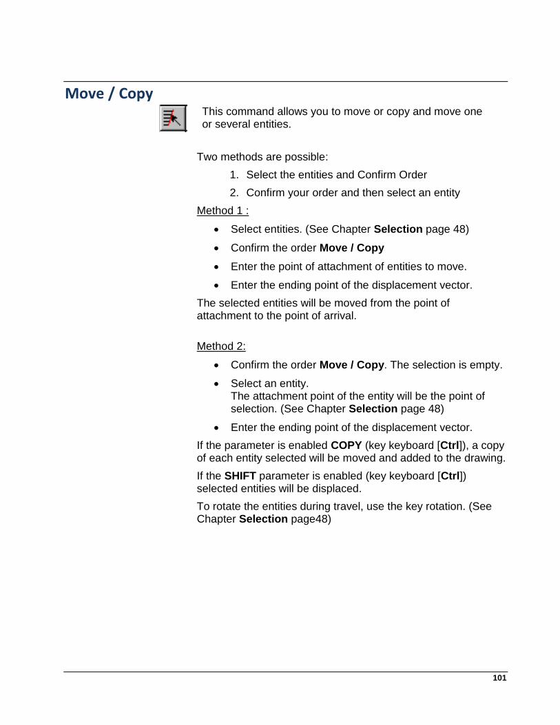
101
Move / Copy
This command allows you to move or copy and move one or several entities.
Two methods are possible:
1. Select the entities and Confirm Order
2. Confirm your order and then select an entity
Method 1 :
Select entities. (See Chapter Selection page 48)
Confirm the order Move / Copy
Enter the point of attachment of entities to move.
Enter the ending point of the displacement vector.
The selected entities will be moved from the point of attachment to the point of arrival.
Method 2:
Confirm the order Move / Copy. The selection is empty.
Select an entity. The attachment point of the entity will be the point of selection. (See Chapter Selection page 48)
Enter the ending point of the displacement vector.
If the parameter is enabled COPY (key keyboard [Ctrl]), a copy of each entity selected will be moved and added to the drawing.
If the SHIFT parameter is enabled (key keyboard [Ctrl]) selected entities will be displaced.
To rotate the entities during travel, use the key rotation. (See Chapter Selection page48)
102
Repeat two directions
This command lets you copy selected entity by repetition in two directions.
Select entities. (See Chapter Selection)
Confirm the order by Repetition 2 directions
Enter the number of repetition in the 1st direction.
Enter the no repetition in the 1st direction. (2 points defining a vector)
Enter the number of repetition in the 2nd direction. (If one wants a repeat in one direction, enter 0)
Enter the no repetition in the 2nd direction. (2 points defines a vector) (If the repeat count is greater than 0)
Circular Repeat
This command lets you copy selected entity by repetition around a point.
Select entities. (See Chapter Selection)
Confirm Order repeat circular
Enter the point center of rotation
Enter the rotation angle of each step of repeating
Enter the number of repetition direction

103
Rotation
This command will rotate through three points: the center point of departure and arrival point.
Sélectionnez des entités
Validez la commande Rotation 3 points
Sélectionnez un centre de rotation O.
Sélectionnez un point de départ de la rotation P1.
Sélectionnez un point d’arrivée de la rotation P2.
La rotation de centre O d’angle OP1,OP2.
Rotation angle
Dans la fonction "Rotation 3 Points", pour activer cette option, il suffit d'indiquer la valeur de l'angle que la rotation doit effectuer dans la zone de saisie Dir :

104
Explode Entities
This toolbar (Alt + B) can explode:
circles.
ellipses.
poses.
sub drawings.
catalogs.
To explode an entity simply choose the appropriate tool icon and then point the entities desired.
For arcs and ellipses, the program itself calculates the number of segments to be created to meet the best form of the entity.
For other entities (sub-design, catalog, postures), all the component entities are copied into the current drawing and the reference to the drawing, catalog or model fitting is removed.

105
Profiles Creating and deleting a profile. A profile is a set of combined entity to determine a contour or a continuous route.
This feature is particularly useful in calculating surfaces, to be hatched areas, to define a contour or offset to optimize a tool path.
Profil manual Allows you to select one by one the entities that make up a profile. The entities are not changed. To make the selection and create a profile, simply click in an area where there is no entity. The program then validates Profile.
Profile interactive manual
Permit reliance on a construction or on existing entities. To use this function you must: 1. define a starting point of the profile (eg intersection.), 2. select the entity on which the profile begins, 3. select an entity that determines the course of the profile, 4. repeat step 3 until the end of the course profile. 5. Enter a blank area to stop the creation of entity. This function is not used to directly create the entity profile, but to create finite entities (segments, arcs) that are based on a geometrical construction (lines, circles).

106
Contour shifted This feature allows you to create a contour shifted from a profile.
The profile may be non-continuous,
The profile can be open,
The profile may be undirected (for use in profile window).
In the drawing above, we have the example of two contours shifted to 5 (green) and -5 (blue) following a profile (red) are not continuously open and unoriented. 1. Select Profile
2. Enter the offset value
3. Validate desired COUTOUR (interior and / or outside)
Select a Profile
This feature allows you to directly select all the elements of a profile.The Move function moves the entire profile (including hatching if they are associated) and the Copy function ([Ctrl]) allows to obtain a copy of the profile entities.

107
Profile window
Lets you enter through a window selection all entities which make up a profile.
Remove profile Allows you to delete a profile by selecting an entity that composes it. Note: If hatching is linked to the profile, this function automatically erases and it shows in the status bar the number of hatching erased
Area profile
Calculates the area defined by the profile. Note the calculated area is the area of the shaded area that would function by Crosshatch Profile.
Results of calculation: In addition to the surface and center of gravity, the program also calculates the inertia and the main compound and the volume of revolution generated by rotating the surface around the axis Ox.

108
The Hatch Creating and deleting hatching.
Crosshatch profile
Used to hatch a profile by selecting an entity that composes this profile.
Remove hatching Deletes hatching associated with a profile by selecting an entity that composes this profile.
Control of hatching To display the dialog box that controls the hatching

109
Layout
Grouping entities
Cette commande permet de grouper des entités afin de constituer un modèle permettant de des impositions impositions .
Select entities.
Confirm the Group command
Enter the group number (model)
All selected entities belong to the group so defined. This group design may be supplemented or amended. All the poses associated be complemented or amended.
Fitting dynamic
This command lets you create dynamic poses.
Select a model)
Move the insertion until the desired position. (To rotate the installation, use the rotation).
Impose
This command allows you to make charges or nestings of poses by rehearsing or optimization in a given format.

110
The following dialog box lets you define the type of tax to achieve.
Repeat
Enter the group (model) to repeat.
Enter the number of repetitions in X (1st direction)
Enter the number Repeat in Y (2nd direction)
Enter the no repetition in the 1st direction. (2 points defines a vector)
Enter the no repetition in the second direction. (2 points defines a vector) (If the repeat count is greater than 0)
Impose
Enter the group (model) to repeat.
Enter the format of the X position
Enter the format of the Y position
Imbricate
Enter the group (model) to repeat.
Enter the format of the overlapping X
Enter the format of the nesting Y
Enter the no overlap in Y only. (2 points defines a vector)

111
Mirror
If the mirror box is checked :
Enter the no reversal in Y only. (2 points defining a vector: point to move, point to reach)
A final table will show the result of the imposition.

112
Move Model This menu processing, allows to move a model used in a taxation without moving poses. In effect arises is an image of the model which we applied a moving and / or rotation. To maintain the geometric position poses during a trip model, we must recalculate the displacement and rotation equivalent to a pose that is what this function for you.
Explode poses The Explode poses optionthe Tools menu allows burst a pose in as many entities that comprise it. There are two ways to break one or more poses:
1. Explode poses that are selected. To do this, select all the poses you want to explode and then choose the option poses Explode the tools menu.
2. Explode poses on the fly. To do this, choose Explode poses the Tools menu, then with the mouse select the poses you want to explode.
Note :
When breaks between sets, entities are created in the group of model fitting, and consequently there are other exposures on the same group model these new entities appear in the poses. We must change the group attribute of the new entities to avoid having this behavior.

113
Les informations
This function displays information about the film, models (number of hauls, number of bends, overall size, ..). The File button allows you to create a text file containing all the information for later use. It is also possible to select all the text in the dialog box and copy to clipboard from MS-Windows.

114
Data base This dialog box provides access to properties of entities in the database. To change a property of an entity, we may move in the tree database (the entities are detected simultaneously in the drawing area) is giving its number in the text field (above the button position ) and press Set. When the entity is chosen, simply position the tree to access its properties. The Field property adapts its title based on the ownership of the entity. Modify the property and confirm the change with the Apply button.
The associations of entities are not editable by the database. They are only available.

115
Inserting files
It is possible to insert drawings as a base map and catalogs from the Edit menu option Insert.
The drawing You can put any design in the format PICADOR ®. The inserted file is then linked to the active drawing. It can not be changed. If you wish to delete the link below and copy the design must use the Tools Menu Explode Under Drawing.
After choosing the design to add in, it must give the similarity coefficient that determines the scale of the sub drawing. If scores are present in the drawings in the value of the rating invariant. For example, if a by drawing contains a distance value 100.00 rating, placing it in a drawing at a scale of 0.5 does not change the display of the value of the score that show always 100.00.
We can then move on drawing with the mouse and use buttons for rotations (see chapter selection).

116
Les catalogues
We can insert coins or a multiple catalogs graces the menu Insert Catalogs. It is imperative that the current file exists on disk to use this feature. The catalog files are special files with the extension PICADOR ® CD. The dialog box for inserting catalogs can view all parts of a catalog from a choice of several catalogs (maximum 12). The list box displays the names of catalogs catalogs including at least one part is referenced in the file or else it is marked free. You can add a catalog using the Add button, but to be validating a catalog must be referenced by at least one of its parts. You can delete a catalog and all exhibits referenced by it with the Remove button.
Copy: A document catalog may be linked to the file through the catalog, or copied from the catalog. In the latter case, the reference to the catalog is no longer necessary because all the entities that make up part of the design are.

117
Flip Horizontal:
Check the box if you want to get the symmetrical horizontal part catalog selected.
To obtain symmetrical about the vertical symmetry Hor check.
And use the button (home) to rotate 180°.
Do not confirm : When the piece catalog is selected (double click) and if the Do not confirm is checked, part catalog will insert to the size of that recorded in the Catalogue.
If unchecked, the following dialog box allows to design the piece catalog.
Hide window: This option will hide the window when the catalogs were selected element. To have the window appear again just press
the button Echap
For the nomenclature of a piece catalog, simply click the right mouse button to display the following window.

118
Images Bimaps You can insert a bitmap into a drawing Picador.
To do this simply use the Edit Insert Image.
When you insert the image, the program asks if you want to keep the original size.
If you answer YES, the image retains its original size and position on the user's drawing. If the answer is NO the user defines the framework
within which the image must fit.
It is therefore a link to the bitmap file. By cons we can define a zone where we display the bitmap and it provides another tool to manipulate and resize.

119
Changing the size of the bitmap:
Use the function: Resizing an image processing
It is possible to apply a symmetry transformation of the image (vertical, horizontal and any axis).

120
THE PARAMETRIC Introduction
This new module integrates directly into the engine parametric PicGEOM.
He uses only listing functions and text (formulas) from a new drawing, a drawing or an existing imported drawing quickly and easily perform a parametric model.
To make a parametric, it suffices : 1. drawing, use an existing drawing or importing a drawing, 2. to classify the film with ratings parameters, choosing the free parameter name. 3. need to define whether the relationship between the parameters (formulas).
test it and save it as a normal drawing.

121
The parametric model thus obtained can then be reused directly and immediately from PicGEOM.
1. Open the parametric drawing. 2. Start executing parametric and enter the paramater (the system takes charge of
analyzing the forms and dimensions parameters to require only the parameters to define)
3. The parametric transformation is immediately obtained. 4. You can then confirm your new drawing, or raise the performance to change the
desired parametric.

122
It can also be added to the standard template library:
1. Generate parametric component(.dll) 2. Add the document in the library (right clic on the location of your choice).

123
Utilisation
Rating parametric horizontal Create an entity rating parameter with the expression of the
parametric constraint.
Enter a 1st point,
Enter a 2nd point,
Enter a point to position the document.
Enter a parameter (eg. L) or an expression ( Ex. B/2+majo5)
The rating will be shown the horizontal projection of two points
Rating parametric vertical Create an entity rating parameter with the expression of the
parametric constraint.
Enter a 1st point,
Enter a 2nd point,
Enter a point to position the document.
Enter a parameter (eg. L) or an expression ( Ex. B/2+majo5)
The rating will be shown the vertical projection of two points
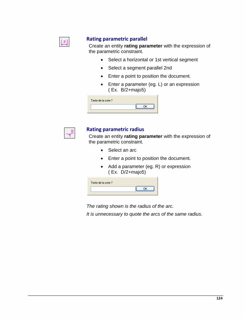
124
Rating parametric parallel Create an entity rating parameter with the expression of
the parametric constraint.
Select a horizontal or 1st vertical segment
Select a segment parallel 2nd
Enter a point to position the document.
Enter a parameter (eg. L) or an expression ( Ex. B/2+majo5)
Rating parametric radius Create an entity rating parameter with the expression of
the parametric constraint.
Select an arc
Enter a point to position the document.
Add a parameter (eg. R) or expression ( Ex. D/2+majo5)
The rating shown is the radius of the arc.
It is unnecessary to quote the arcs of the same radius.

125
Formulas
This feature allows you to define the parameters and relations between the parameters.
* Enter arithmetic expressions (variable = expr)
* Enter [Enter] to change expression
* Click [OK]
* Click an anchor point on the design formulas.
Operators are available :
+(plus) -( minus) *( multiply) /( divide)
The assignment operator is: =( equals)
The variables and parameters must begin with a letter. Uppercase and lowercase are interpreted differently.
B is different as b
Ep is different as ep

126
The arithmetic and trigonometric
Abs(expr) returns the absolute value of the expression expr ACosd(expr) returns the angle whose cosine is the expression expr ASind(expr) returns the value whose sine is the expression expr ATand(expr) returns the value of the angle whose tangent is the
expression expr cosd(expr) returns the cosine of the angle expr (degrees) sind(expr) returns the sine of the angle expr (degrees) tand(expr) returns the value of the tangent of the angle expr
(degrees) Sqrt(expr) returns the square root of expression expr (expr)^2
returns the square of the expression expr
tand(angle)=BC/AB -----> BC=tand(angle)*AB cosd(angle)=AB/AC -----> AB=cosd(angle)*AC sind(angle)=BC/AC -----> BC=sind(angle)*AC
Pythagore: (BC*BC+AB*AB)=AC*AC -------> AC=Sqrt(BC*BC+AB*AB)
Create a condition: (for example, A,B,C are parameters)
if (A>B) A=B if (A+B>C) A=10

127
The parameter definition table:
The table is used to declare the creation of parameters, their description information (length, width, height ...) and assign a default.
Execute Parametric
This function allows you to enter the settings and to run the setup with the defined constraints. The system automatically analyzes the data and prompts for undefined parameters.
Clean This function deletes all parameter data (dimensions,
formulas) to validate the new drawing obtained.
Generate a parametric component This function transforms the setting into .dll component, the
model becomes usable in the parametric model library.
Edit parametric component This function allows you to edit an existing .dll component.
Recommended