Physics 53600
Electronics Techniques for Research
Spring 2020 SemesterProf. Matthew Jones

Simulating Circuits using SPICE
• After the invention of planar integrated circuits, analog designs became increasingly complex
• The time required to fabricate a design became much longer
• It was no longer possible to adjust component values to optimize circuit performance
• There was a need to accurately model analog electronic circuits in the design process

SPICE
• Simulation Program with Integrated Circuit Emphasis– Initial concept developed in the 1960’s– SPICE 1 released into public domain May 1972– SPICE 2 released in 1975– SPICE 3 released in March 1985– SPICE 3f.5 released in 1993
• Commercial versions– PSPICE (Cadence Design Systems)– HSPICE (Synopsys)
• Free spinoffs:– ADICE (Analog Devices)– LTspice (Liner Technologies Analog Devices)– A few others

Defining Circuits
• SPICE performs numerical simulation of circuits
– All components must have numerical values

Defining Circuits
• Simulation of the circuit requires translating the schematic into a representation that can be interpreted by SPICE.
• This representation is called the netlist
• First, assign labels to each node in the circuit
• Then specify which components are connected to the nodes

Defining Circuits
• It is necessary to assign a ground node “0” in each disconnected part of the circuit
• Other nodes can have arbitrary labels

Defining Circuits
• The netlist consists of a list of all components and the nodes to which they are connected
– Resistors:
– Voltage sources:
• This is the complete netlist:
Assumes ohms

Defining Circuits
• Some minor additions are needed
– A title for the circuit
– What type of numerical analysis to perform?
– The end
DC operating point analysis

SPICE Output
Voltages of each node(electric potential with respect to ground)
Current through each voltage source
Resistor models(with temperature coefficients)
Current and power for each resistor
Current and power for each voltage source

SPICE Output
• All the current flowing from V1 must pass through R2• All the current flowing from V2 must flow through R1• Current flowing through R3 must be the sum of these currents
• SPICE reports the current flowing into the positive node of voltage sources.

Transient Analysis
Netlist:100 Ω

Transient Analysis
• What range of resistances will produce oscillations?
𝑅2
4𝐿2<
1
𝐿𝐶• Expect oscillations for 𝑅 < 590 Ω
• Oscillation frequency is 𝑓 =𝜔
2𝜋=
1
𝐿𝐶−
𝑅2
4𝐿2
• When 𝑅 = 100 Ω, 𝑓 = 101 𝑘𝐻𝑧

Transient Response
R = 100 Ω R = 600 Ω
Remember that the current is measured flowing INTO the positive node of the voltage source

A Low-Pass Filter Example
• Inductors pass low frequencies (just a wire for DC)
• Capacitors pass high frequencies

A Low-Pass Filter Example
• Voltage source defined using

A Low-Pass Filter Example
• The inductor blocks the high frequency components and rounds off the sharp corners.

Using LTspice
• LTspice was developed by Linear Technologies and was used in-house for IC and power supply circuit design
• In addition to circuit simulation, it provides a graphical schematic entry interface
• In July 2016, Analog Devices acquired Linear Technologies (amicably) for $14.8 billion in cash and stock
• https://www.analog.com/en/design-center/design-tools-and-calculators/ltspice-simulator.html
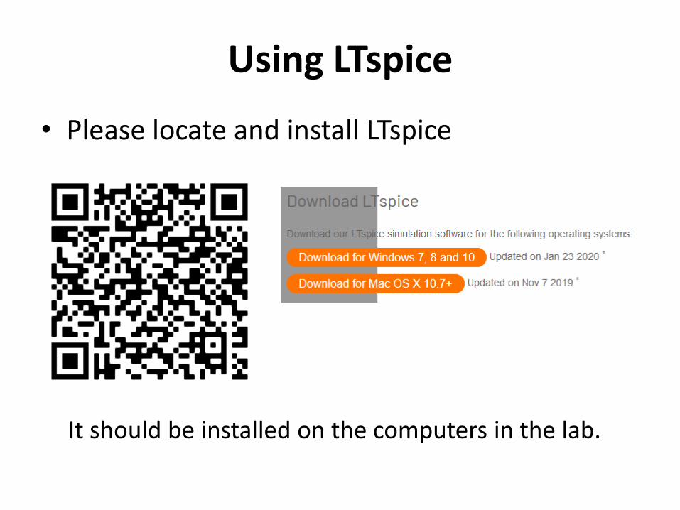
Using LTspice
• Please locate and install LTspice
It should be installed on the computers in the lab.

Using LTspice
• There is lots of documentation and tutorial videos. Just ask señor google…

Using LTspice

Frequency Analysis
The AC analysis will scan the frequency of a voltage source and plot the ratio voltages and the relative phase

Frequency Analysis
Expected cutoff frequency,
𝑓−3 𝑑𝑏 =𝑅
2𝜋𝐿= 1𝑀𝐻𝑧
-3 db
45 degrees

Transformers
• Transformers are described by individual inductors with a specified coupling

Transformers
Notes:• Make sure to define ground on BOTH sides of the transformer• Alternatively connect both sides by a LARGE resistor
Recommended


![Registration Number 1990/000900/30 [hereinafter referred ... · Registration Number 1990/000900/30 [hereinafter referred to as Transnet] REQUEST FOR QUOTATION [RFQ] No PTH/53600](https://img.pdfslide.us/doc/110x75/5e796bf17a6495651820663e/registration-number-199000090030-hereinafter-referred-registration-number.jpg)