Owner´s manual
TDAI 2200

2
3
Table of Contents
Operating Voltage 4
Unpacking the TDAI 2200 4
Serial Number Registration 4
Introduction 5
Accessories 6
Front Panel 7
Rear Panel 8
Display Indicators 9
Remote Control 10
Menu System 11 - Navigating the menu system 11
Menu Tree 12
Display 13 - Display Timeout 13 - Disp. Brightness 13 - Volume Display Timeout 13
Volume 14 - Def. Vol. 14 - Max. Vol. 14
Input Name 15
Input Sensitivity 15
Advanced setup 16 - Communication 16 - Comm Address 16 - Comm Speed 16 - Master/Slave 16 - Line Out 17 - Line Out Control 17 - Line Out Level 17 - Routing 17 - Crossover frequency 18 - Filter type 18 - Delay 19 - Trigger Setup 19 - Remote Control 20 - Software versions 20 - Factory Reset 20
Software upgrading 21
Connectors 22 - Mains Connector 22 - Loudspeaker Connectors 22 - Trigger Connector 22 - Optional AD Converter Board 23 - Balanced inputs 23 - Unbalanced inputs 23
Cleaning and Maintenance 23
Technical Specifi cations 24 - Audio 24 - Protection 25 - Mains 25 - Trigger 25 - Mechanical 25
Technical Assistance 26
Manual version 02-07-07
4
Operating Voltage
The TDAI 2200 is available in two versions: one for 115V mains voltage and another for 230V mains volt-age.
Check the label on the TDAI 2200 rear panel and verify you have the version with the proper voltage for your area.The 115V version requires a mains voltage of 110V-120V at 50-60Hz with a current rating of 8A.The 230V version requires a mains voltage of 220V-240V at 50-60Hz with a current rating of 4A.The mains voltage setting for your TDAI 2200 can be changed ONLY BY A QUALIFIED ENGINEER.
Connect the power input only to the AC source printed on the label. The warranty will not cover any damage caused by connecting to the wrong type of AC mains.
The TDAI 2200 has three power modes:OFF 1.
No circuitry is powered.
STANDBY 2. The mains transformer and amplifi er section are powered off - only the remote control input and the mi-croprocessor is powered, so the unit can be powered up using the remote control ‘STANDBY’ button.
ON 3. All circuits active.
Unpacking the TDAI 2200
Carefully remove the unit and accessory kit from the carton, visually check for shipping damage.Contact both the shipper and your Lyngdorf Audio representative immediately if the unit bears any sign of damage from mishandeling. All Lyngdorf Audio equipment is carefully inspected before leaving our factory.
Keep shipping carton and packing material for future use or in the unlikely event that the unit needs servicing. If this unit is shipped without the original packing, damage could occur and void the warranty.
Serial Number Registration
Please record the serial number of your amplifi er here for future reference. The serial number is printed on the label on the TDAI 2200 rear panel. You will need this serial number, should you ever require service for your TDAI 2200 amplifi er.
TDAI 2200 serial number: _____________________
5
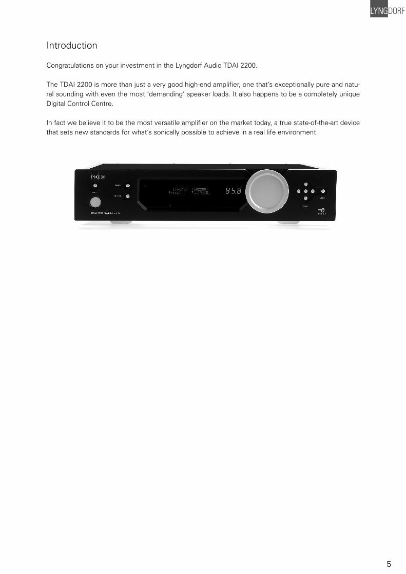
Introduction
Congratulations on your investment in the Lyngdorf Audio TDAI 2200.
The TDAI 2200 is more than just a very good high-end amplifi er, one that’s exceptionally pure and natu-ral sounding with even the most ‘demanding’ speaker loads. It also happens to be a completely unique Digital Control Centre.
In fact we believe it to be the most versatile amplifi er on the market today, a true state-of-the-art device that sets new standards for what’s sonically possible to achieve in a real life environment.
6
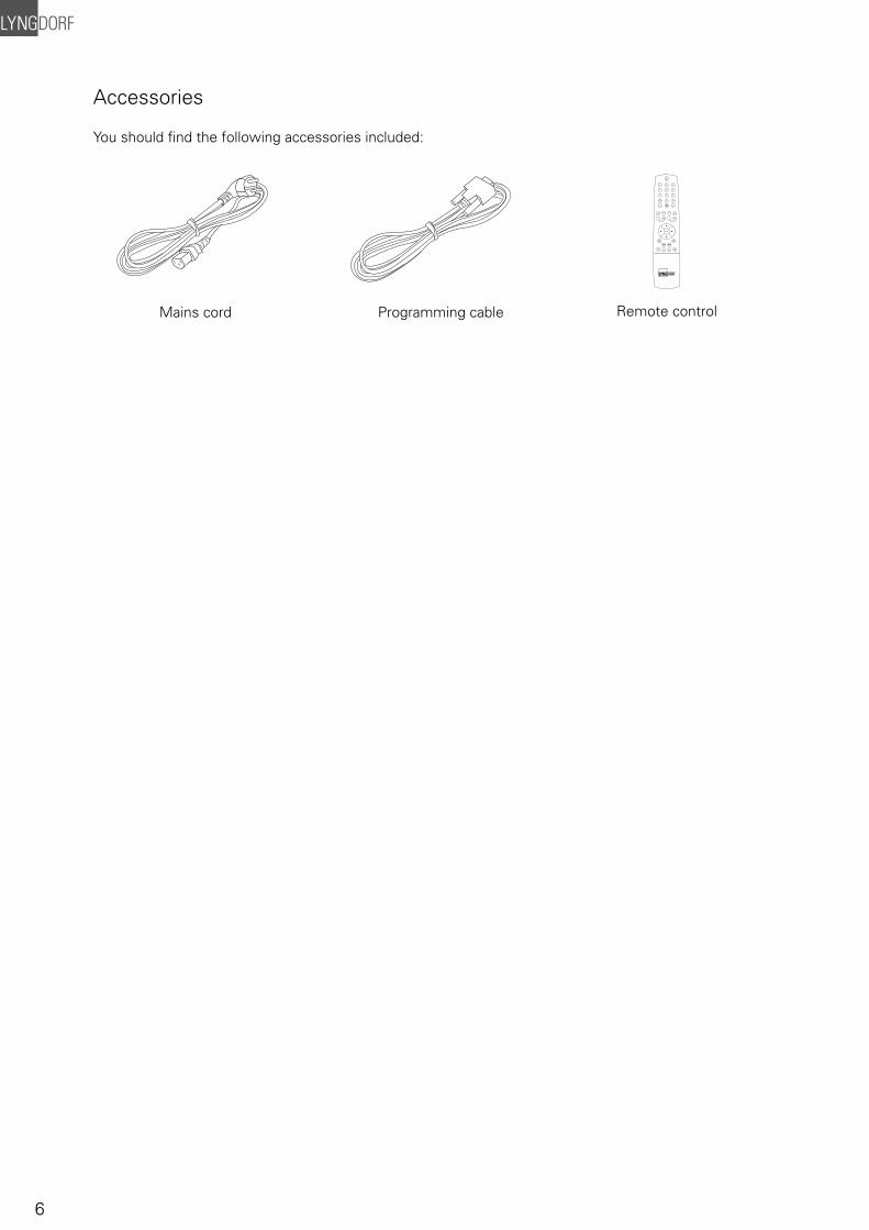
Accessories
You should fi nd the following accessories included:
1 2 3
4 5 6
7
digital info
analog
A/Brandom repeat
AMP
channel
ENTER
volume
RCS CD TUNER
menu
8
0
9
Mains cord Programming cable Remote control
7
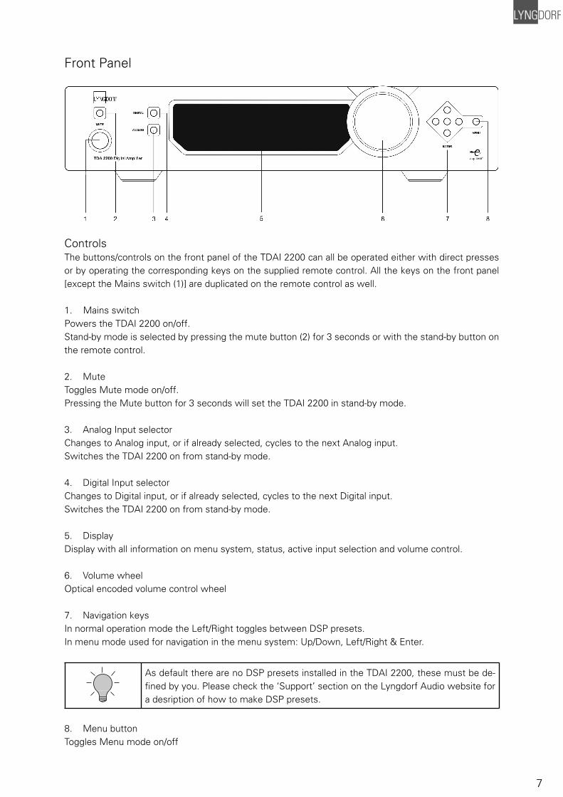
Front Panel
ControlsThe buttons/controls on the front panel of the TDAI 2200 can all be operated either with direct presses or by operating the corresponding keys on the supplied remote control. All the keys on the front panel [except the Mains switch (1)] are duplicated on the remote control as well.
1. Mains switch Powers the TDAI 2200 on/off. Stand-by mode is selected by pressing the mute button (2) for 3 seconds or with the stand-by button on the remote control.
2. Mute Toggles Mute mode on/off. Pressing the Mute button for 3 seconds will set the TDAI 2200 in stand-by mode.
3. Analog Input selector Changes to Analog input, or if already selected, cycles to the next Analog input.Switches the TDAI 2200 on from stand-by mode.
4. Digital Input selectorChanges to Digital input, or if already selected, cycles to the next Digital input.Switches the TDAI 2200 on from stand-by mode.
5. Display Display with all information on menu system, status, active input selection and volume control.
6. Volume wheel Optical encoded volume control wheel
7. Navigation keys In normal operation mode the Left/Right toggles between DSP presets. In menu mode used for navigation in the menu system: Up/Down, Left/Right & Enter.
As default there are no DSP presets installed in the TDAI 2200, these must be de-fi ned by you. Please check the ‘Support’ section on the Lyngdorf Audio website for a desription of how to make DSP presets.
8. Menu button Toggles Menu mode on/off
8
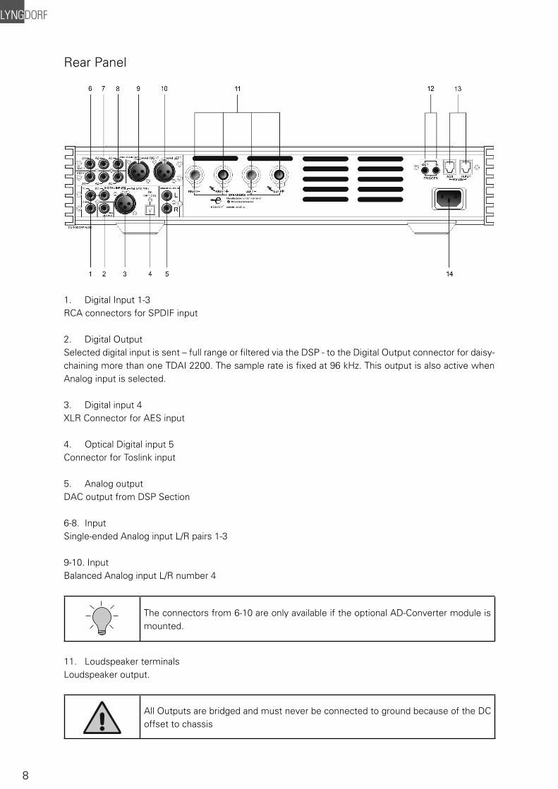
Rear Panel
1. Digital Input 1-3 RCA connectors for SPDIF input
2. Digital Output Selected digital input is sent – full range or fi ltered via the DSP - to the Digital Output connector for daisy-chaining more than one TDAI 2200. The sample rate is fi xed at 96 kHz. This output is also active when Analog input is selected.
3. Digital input 4 XLR Connector for AES input
4. Optical Digital input 5 Connector for Toslink input
5. Analog output DAC output from DSP Section
6-8. Input Single-ended Analog input L/R pairs 1-3
9-10. Input Balanced Analog input L/R number 4
The connectors from 6-10 are only available if the optional AD-Converter module is mounted.
11. Loudspeaker terminals Loudspeaker output.
All Outputs are bridged and must never be connected to ground because of the DC offset to chassis
9
12. Trigger Out / In DC Trigger Out for remote start of SDA 2175 power amplifi ers or similar equipment.Trigger In has no function.
13. RS232 Input/Aux RS232 communication connectors for communication with a PC, remote control from Lyngdorf equip-ment with broadcast commands or linked control between amplifi ers. Input is looped to Aux out for dai-sy-chaining of amplifi ers. The ‘INPUT’ is used for connection to a PC for software update, or as a control input from a Lyngdorf Master Amplifi er. The ‘AUX’ connection is output in Master mode for controlling slave amplifi ers, or bypasses input from other master amplifi ers to the next amplifi er.
14. Mains Input
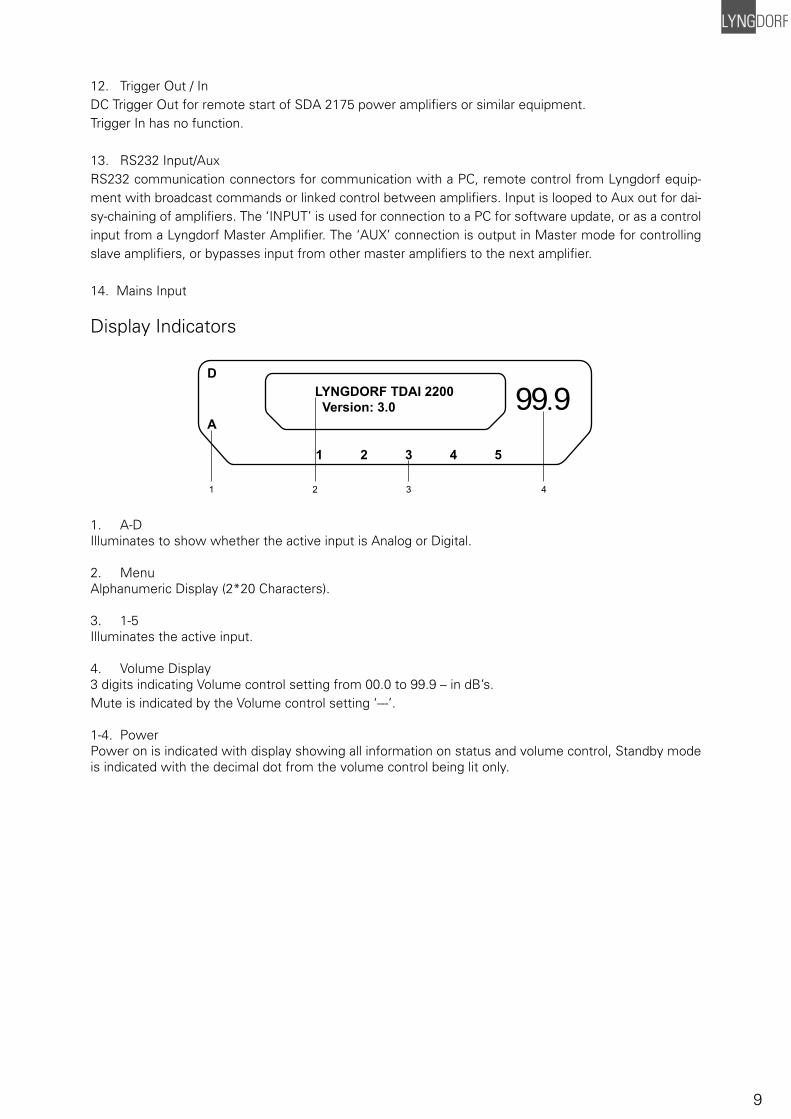
Display Indicators
1. A-DIlluminates to show whether the active input is Analog or Digital.
2. MenuAlphanumeric Display (2*20 Characters).
3. 1-5 Illuminates the active input.
4. Volume Display3 digits indicating Volume control setting from 00.0 to 99.9 – in dB’s.Mute is indicated by the Volume control setting ‘---’.
1-4. PowerPower on is indicated with display showing all information on status and volume control, Standby mode is indicated with the decimal dot from the volume control being lit only.
LYNGDORF TDAI 2200 Version: 3.0
D
A
1 2 3 4 5
99.9
1 2 3 4
10
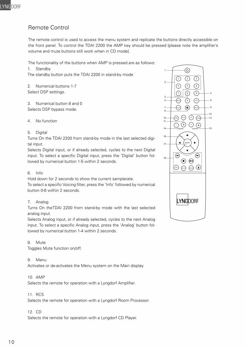
Remote Control
The remote control is used to access the menu system and replicate the buttons directly accessible on the front panel. To control the TDAI 2200 the AMP key should be pressed [please note the amplifi er’s volume and mute buttons still work when in CD mode].
The functionality of the buttons when AMP is pressed are as follows:
1 2 3
4 5 6
7
digital info
analog
A/Brandom repeat
AMP
channel
ENTER
volume
RCS CD TUNER
menu
8
0
9
1
2
53
4
6
9
12
13
78
1011
14
16
17
18
15
1. StandbyThe standby button puts the TDAI 2200 in stand-by mode.
2. Numerical buttons 1-7 Select DSP settings.
3. Numerical button 8 and 0Selects DSP bypass mode.
4. No function
5. Digital Turns On the TDAI 2200 from stand-by mode in the last selected digi-tal input.Selects Digital input, or if already selected, cycles to the next Digital input. To select a specifi c Digital input, press the ‘Digital’ button fol-lowed by numerical button 1-5 within 2 seconds.
6. Info Hold down for 2 seconds to show the current samplerate.To select a specifi c Voicing fi lter, press the ‘Info’ followed by numerical button 0-6 within 2 seconds.
7. Analog Turns On theTDAI 2200 from stand-by mode with the last selected analog input.Selects Analog input, or if already selected, cycles to the next Analog input. To select a specifi c Analog input, press the ‘Analog’ button fol-lowed by numerical button 1-4 within 2 seconds.
8. Mute Toggles Mute function on/off.
9. Menu Activates or de-activates the Menu system on the Main display.
10. AMP Selects the remote for operation with a Lyngdorf Amplifi er.
11. RCS Selects the remote for operation with a Lyngdorf Room Processor.
12. CD Selects the remote for operation with a Lyngdorf CD Player.
11
13. Tuner No function.
14. Channel -/+ Toggles down/up between inputs.
15. Volume Up/down Changes volume in the chosen direction.
16. Up / Down / Left / Right In normal operation mode the Left/Right toggles between DSP presets.In menu mode they are used for navigation in the menu system. Pressing and holding down a key changes selected values fast.
As default there are no DSP presets installed in the TDAI 2200, these must be de-fi ned by you. Please check the ‘Support’ section on the Lyngdorf Audio website for a desription of how to make DSP presets.
17. Enter Turns the TDAI 2200 On from stand-by mode with the last selected input and works as Enter in menu system.
18. No function.
Menu System
The Main Display on the front panel of the TDAI 2200 shows all functionality and current status of the TDAI 2200. An overview of the menu tree can be seen in the ‘Menu Tree’ chapter. When the amplifi er is powered up the Main screen shows the product name and current software ver-sion.
After showing the initial screen the main screen is shown. Here the current Input, DSP Preset and Sample Frequency is displayed. Input name can be changed in the ‘Input Name’ menu, for DSP presets please refeer to the ‘Support’ section on the Lyngdorf Audio website. If a digital input is active the source samplerate is detected and displayed, if the Analog input board is mounted and selected the ADC sam-plerate 96 kHz will be displayed.
Furthermore the Volume Control is set according to the standard settings which can be altered in the ‘Volume’ menu.
Navigating the menu systemPressing the Menu button on the remote or the front panel access the top level of the Menu system.
Using the left/right arrows keys the Menu system settings can now be scrolled through. To access a sub menu setting just scroll to it and press the Enter button. To change a setting, use the up/down arrows and press Enter to accept the change, or Menu to exit without applying any changes.
12
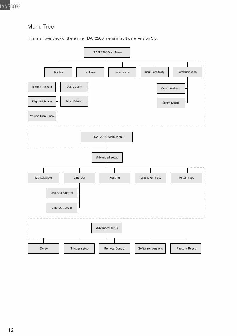
Menu Tree
This is an overview of the entire TDAI 2200 menu in software version 3.0.
Volume Disp.Timeo.
Display Timeout
Disp. Brightness
Input NameVolumeDisplay
Def. Volume
Max. Volume
Input Sensitivity Communication
Comm Address
Comm Speed
TDAI 2200 Main Menu
Advanced setup
Line OutMaster/Slave
Line Out Control
Line Out Level
Routing Crossover freq. Filter Type
TDAI 2200 Main Menu
Delay Trigger setup Remote Control Software versions Factory Reset
Advanced setup
13
Display
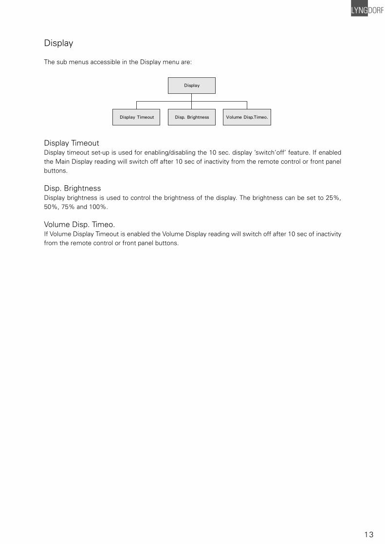
The sub menus accessible in the Display menu are:
Display TimeoutDisplay timeout set-up is used for enabling/disabling the 10 sec. display ’switch’off’ feature. If enabled the Main Display reading will switch off after 10 sec of inactivity from the remote control or front panel buttons.
Disp. BrightnessDisplay brightness is used to control the brightness of the display. The brightness can be set to 25%, 50%, 75% and 100%.
Volume Disp. Timeo.If Volume Display Timeout is enabled the Volume Display reading will switch off after 10 sec of inactivity from the remote control or front panel buttons.
Volume Disp.Timeo.Display Timeout Disp. Brightness
Display
14
Volume
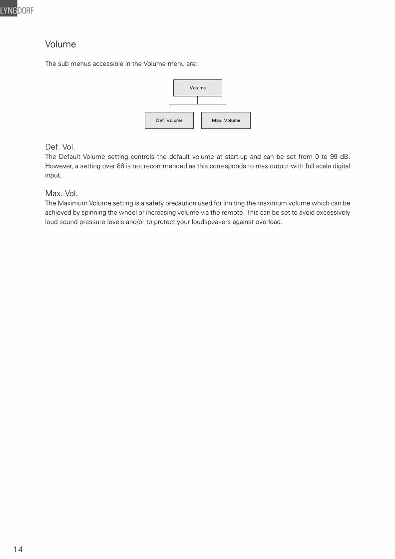
The sub menus accessible in the Volume menu are:
Def. Vol.The Default Volume setting controls the default volume at start-up and can be set from 0 to 99 dB. However, a setting over 88 is not recommended as this corresponds to max output with full scale digital input.
Max. Vol.The Maximum Volume setting is a safety precaution used for limiting the maximum volume which can be achieved by spinning the wheel or increasing volume via the remote. This can be set to avoid excessively loud sound pressure levels and/or to protect your loudspeakers against overload.
Volume
Def. Volume Max. Volume
15
Input Name
As default, digital inputs are called Digital 1-5 and Analog inputs are called Analog 1-4. To change the name, choose an input and then between the following preset names:
ADC, Analog 1-4, AUX, CD, CD-1, CD-2, DAB, DAT, DBS, DCC, Digital 1-5, DVD, DVD-1, DVD-2, FM, LD, • MD, PC, PHONO, RADIO, RIAA, SACD, SAT, TAPE, TUNER, TV, VCR, VDP, VIDEO, VIDEO-1, VIDEO-2.
Input Sensitivity
The Sensitivity adjustment enables you to match levels from different sources as well as obtaining full scale output on your amplifi er. The Sensitivity can be adjusted +/-12dB in 0.1 dB steps.
Setting the Sensitivity too high will result in clipping/distortion. Therefore, always use your ears when setting the Sensitivity
Input Name
Input Sensivity
16
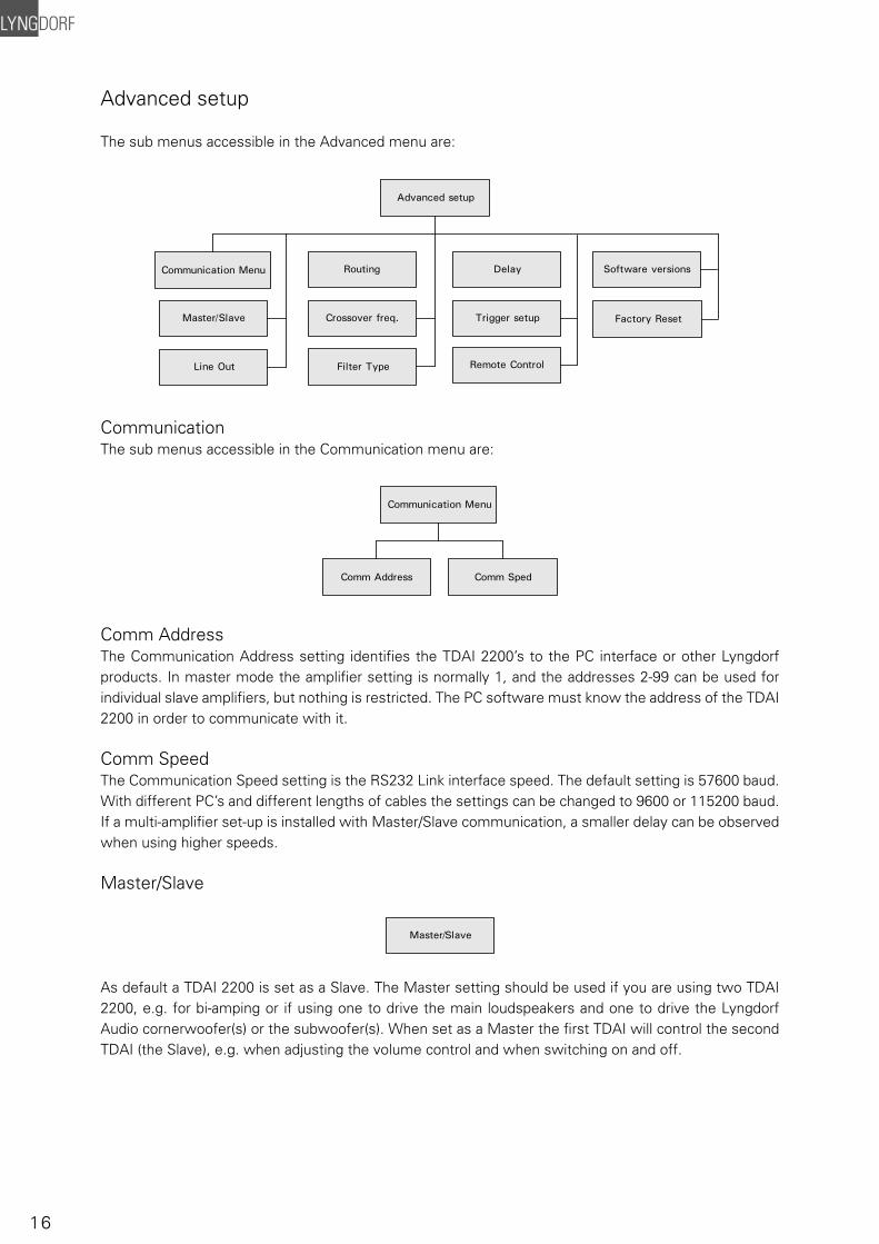
Advanced setup
The sub menus accessible in the Advanced menu are:
CommunicationThe sub menus accessible in the Communication menu are:
Comm AddressThe Communication Address setting identifi es the TDAI 2200’s to the PC interface or other Lyngdorf products. In master mode the amplifi er setting is normally 1, and the addresses 2-99 can be used for individual slave amplifi ers, but nothing is restricted. The PC software must know the address of the TDAI 2200 in order to communicate with it.
Comm SpeedThe Communication Speed setting is the RS232 Link interface speed. The default setting is 57600 baud. With different PC’s and different lengths of cables the settings can be changed to 9600 or 115200 baud. If a multi-amplifi er set-up is installed with Master/Slave communication, a smaller delay can be observed when using higher speeds.
Master/Slave
As default a TDAI 2200 is set as a Slave. The Master setting should be used if you are using two TDAI 2200, e.g. for bi-amping or if using one to drive the main loudspeakers and one to drive the Lyngdorf Audio cornerwoofer(s) or the subwoofer(s). When set as a Master the fi rst TDAI will control the second TDAI (the Slave), e.g. when adjusting the volume control and when switching on and off.
Advanced setup
Line Out
Communication Menu
Master/Slave
Routing
Crossover freq.
Filter Type
Delay
Trigger setup
Remote Control
Software versions
Factory Reset
Communication Menu
Comm Address Comm Sped
Master/Slave
17
Line OutThe sub menus accessible in the ‘Line Out’ menu are:
Line Out ControlThe Line Out Control sets the output level to be Full Scale (fi xed) or regulated.Fixed means there’s a constant full scale output – most often used as ‘tape out’ or when using a Lyngdorf Audio TDAI or SDAI as a ‘slave’ amplifi er in a bi-amping set-up. Regulated means that the output level will follow the level of the volume control. This setting is chosen if you have, for instance, a power amplifi er or an active subwoofer connected.
Line Out Level This adjusts the overall output level in steps of - 0.1 db, it can be adjusted up to – 40 db in total.
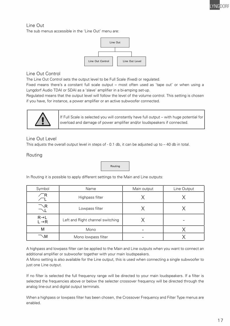
Routing
In Routing it is possible to apply different settings to the Main and Line outputs:
Symbol Name Main output Line Output
RL
Highpass fi lter X X
RL Lowpass fi lter X X
R LL R Left and Right channel switching X -
M Mono - XM Mono lowpass fi lter - X
A highpass and lowpass fi lter can be applied to the Main and Line outputs when you want to connect an additional amplifi er or subwoofer together with your main loudspeakers.A Mono setting is also available for the Line output, this is used when connecting a single subwoofer to just one Line output.
If no fi lter is selected the full frequency range will be directed to your main loudspeakers. If a fi lter is selected the frequencies above or below the selecter crossover frequency will be directed through the analog line-out and digital output terminals.
When a highpass or lowpass fi lter has been chosen, the Crossover Frequency and Filter Type menus are enabled.
Line Out
Line Out Control Line Out Level
Routing
If Full Scale is selected you will constantly have full output – with huge potential for overload and damage of power amplifi er and/or loudspeakers if connected.
18
Crossover frequency
The crossover frequency can be selected anywhere between 40 – 9999Hz.It is very diffi cult to give exact guidelines to setting crossover frequency, fi lter type and order since this depends on the exact drivers and confi gurations. Therefore, the following recommendations should be seen as a good starting point only. In general, the recommended crossover frequency between (sub)woofers and main speakers is be-tween 200 - 400 Hz.By using a high crossover frequency, the rear wall quarter wavelength refl ection is removed from the main speakers.If a Lyngdorf Audio corner woofer is used in a 2+2 set-up, a crossover frequency of 400 is recommended due to the high bandwidth of the corner woofer.For conventional active subwoofers with built in low pass fi lter the recommended crossover frequency is the upper low-pass frequency of the subwoofer.If at all possible, the low pass fi lter in the subwoofer should be bypassed. Due to the quarter wave refl ection from the rear wall corresponding to the depth of the subwoofer cabinet we recommend an crossover point at approximately 200 Hz. You might experiment with turning the subwoofer so the driver faces the wall in a distance of 5 to 10 cm. This will increase the bandwidth of the subwoofer.
However, due to the limited bandwidth (frequency response) of most conventional subwoofers you might fi nd it necessary to choose a lower crossover frequency.
When ‘building’ active speaker systems it is recommended to use the original crossover point(s) used by the manufacturer. Due to the short wavelengths of the mid/high frequencies it is essential that both crossover frequency, fi lter type and order as well as delay is set correctly. Therefore, creating fi lters for active speakers is an iterative process that requires several critical listening sessions in order to achieve seamless integration of the different speaker drivers.
Filter type
It is possible to choose from two different fi lter types in this menu.LiRi: (Linkwitz Riley) 2, 4 or 8 order.
Butw: (Butterworth) 1, 2 or 4 order.
In a 2+2 set-up (main speakers + Lyngdorf Audio corner woofers) we recommend using a fourth order Linkwitz Riley fi lter.In set-ups using conventional active subwoofers – again due to limited bandwidth – we recommend us-ing a second order butterworth fi lter.
In active speaker systems it is recommended starting with a fourth order Linkwitz Riley fi lter.
Crossover freq.
Filter Type
19
Delay
If you are using a set-up with two main loudspeakers located at an identical distance to the listening position you don’t need to set a delay. However, if the distance isn’t identical and/or you are using a sub-woofer, or a Lyngdorf Audio 2+2 system, you need to set a delay in order to ensure that the sound from each loudspeaker reaches the listening position simultaneously. This must be done for main left (ML) and right (MR) and as well as line left (LL) and right (LR).To set the delay all you need do is to measure the distance from each loudspeaker to the listening posi-tion and enter these values in the menu. The necessary delays are then automatically calculated and applied to each channel.
1 centimeter = 0.3937 in
The fault message ‘Values for delay exceed limits’ is displayed when the difference between the distance from the speakers closest to, and the speakers furthest from, the listening position is too big. The biggest difference allowed is 340 cm / 134 in.
If the fault message appears, you can use the following solutions: (Can be used individually or together to achieve a valid set-up with respect to the delay lengths):• Shorten the distances between your Main and Line channel loudspeakers resulting in a more compact loudspeaker set-up. • Arrange your loudspeaker set-up and/or your listening position in a more symmetrical set-up.
Trigger Setup
Trigger setup
Trigger setup sets the usage of the trigger output option. If e.g. an SDA 2175 power amplifi er, subwoofer or similar equipment is connected to Line out, the trigger can be activated and used for switching the connected product on and off.
Delay
20
Remote Control
Remote Control set-up makes it possible to activate or de-activate the remote control. This is useful in set-ups with more than one TDAI 2200 amplifi er in the room. The master amplifi er then becomes the only one receiving signals from the remote, processes them and controls the rest of the TDAI 2200’s over the Lyngdorf RS232 link.
Software versions
The Software version menu is used to check the current software version of your TDAI 2200.
Factory Reset
The Factory Reset is used to restore all settings to the factory settings.
If you return to the factory settings all your personal settings will be erased.
Remote Control
Software versions
Factory Reset
21
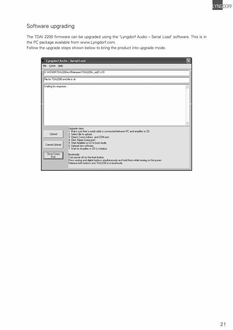
Software upgrading
The TDAI 2200 fi rmware can be upgraded using the ‘Lyngdorf Audio – Serial Load’ software. This is in the PC package available from www.Lyngdorf.com. Follow the upgrade steps shown below to bring the product into upgrade mode.
22
Connectors
Mains ConnectorMains voltage to the TDAI 2200 is applied via an IEC320 type connector. The supplied cable with safety ground should be used to connect the TDAI 2200 to a mains outlet.
Connect the power input only to the AC source printed on the label. The warranty will not cover any damage caused by connecting to the wrong type of AC mains.
Always disconnect the TDAI 2200 from the mains before changing any connections to its inputs or outputs.
Loudspeaker ConnectorsThe TDAI 2200´s loudspeaker connectors accept bare wire ends up to 5 mm in diameter. Connect the wires from each loudspeaker to each channel’s + and – terminals. Do not make any other connections to the output terminals. Ensure the loudspeaker cable is inserted into the slot in the loudspeaker terminal, and the terminal is tightened fi rmly.
Always disconnect the TDAI 2200 from the mains before changing any connections to its inputs or outputs.
Make sure that no conductive part of the loudspeaker wiring is accessible. Do not connect loudspeakers with uninsulated terminals.
When the TDAI 2200 is operating, there is up to 35V DC on its output terminals with reference to ground.
Do not connect the output from the amplifi er to any other amplifi er’s output or any other voltage source. Do not attempt to operate the amplifi er in bridged mono mode.
Trigger ConnectorThe TDAI 2200 is equipped with a TRIGGER OUT 3.5mm mono jack connector. The Trigger signal is a 12V short circuit-protected output signal for powering up external equipment when the TDAI 2200 is on, e.g. remotely connected SDA 2175 power amplifi ers or active subwoofers.
23
Optional AD Converter BoardThe Optional AD Converter card for the TDAI 2200 has input connectors for both balanced (XLR) and unbalanced (RCA) signals. The input impedance of the inputs are 10 kOhm.
Balanced inputsThe balanced XLR inputs are wired in accordance with IEC268:Pin 1: Chassis and ground.Pin 2: Hot (+).Pin 3: Cold (-).Shell: Chassis and ground.
Unbalanced inputsThe unbalanced RCA inputs are wired in accordance with normal practice:Shell: Chassis and ground.Pin: Hot (+).
Cleaning and Maintenance
Make sure that no conductive part of the loudspeaker wiring is accessible. Do not connect loudspeakers with uninsulated terminals.
This unit does not require any regular maintenance except to keep its exterior clean. Simply wipe its exte-rior with a clean soft cloth. A small amount of non-abrasive cleaner may be used on the cloth to remove any excessive dirt or fi ngerprints. Do not use abrasive cleaners or cleaners containing liquid solvents.
24
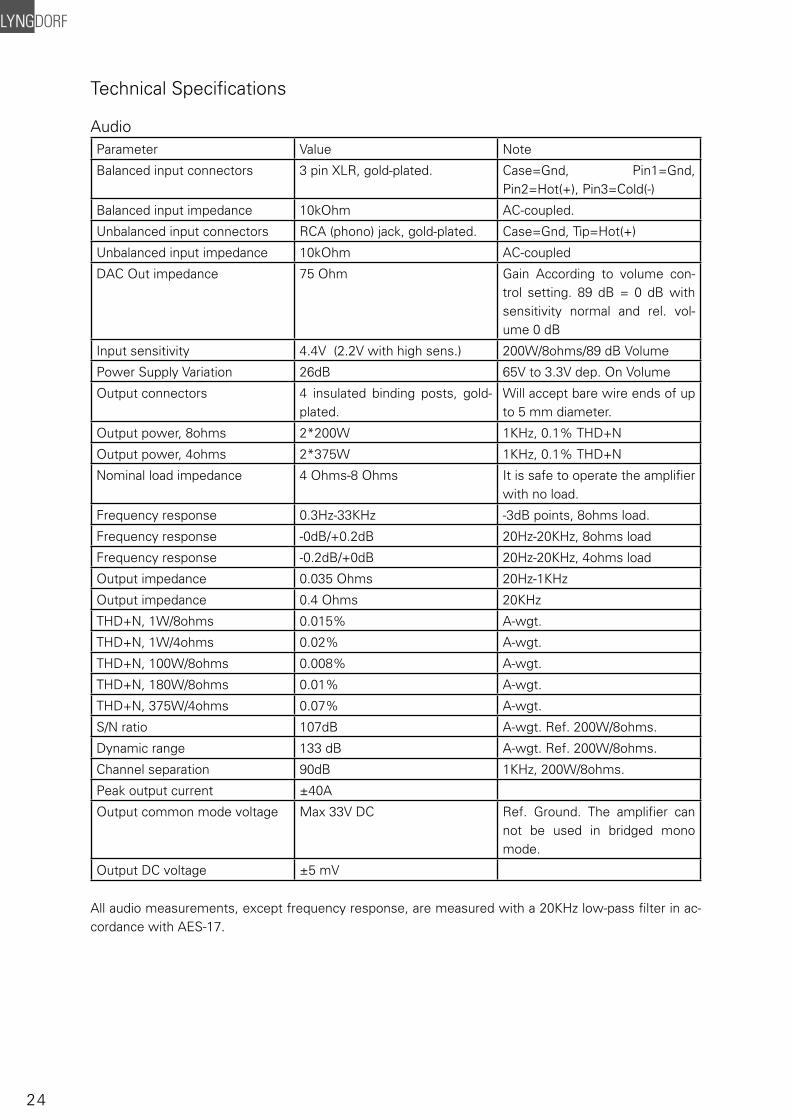
Technical Specifi cations
AudioParameter Value Note
Balanced input connectors 3 pin XLR, gold-plated. Case=Gnd, Pin1=Gnd, Pin2=Hot(+), Pin3=Cold(-)
Balanced input impedance 10kOhm AC-coupled.
Unbalanced input connectors RCA (phono) jack, gold-plated. Case=Gnd, Tip=Hot(+)
Unbalanced input impedance 10kOhm AC-coupled
DAC Out impedance 75 Ohm Gain According to volume con-trol setting. 89 dB = 0 dB with sensitivity normal and rel. vol-ume 0 dB
Input sensitivity 4.4V (2.2V with high sens.) 200W/8ohms/89 dB Volume
Power Supply Variation 26dB 65V to 3.3V dep. On Volume
Output connectors 4 insulated binding posts, gold-plated.
Will accept bare wire ends of up to 5 mm diameter.
Output power, 8ohms 2*200W 1KHz, 0.1% THD+N
Output power, 4ohms 2*375W 1KHz, 0.1% THD+N
Nominal load impedance 4 Ohms-8 Ohms It is safe to operate the amplifi er with no load.
Frequency response 0.3Hz-33KHz -3dB points, 8ohms load.
Frequency response -0dB/+0.2dB 20Hz-20KHz, 8ohms load
Frequency response -0.2dB/+0dB 20Hz-20KHz, 4ohms load
Output impedance 0.035 Ohms 20Hz-1KHz
Output impedance 0.4 Ohms 20KHz
THD+N, 1W/8ohms 0.015% A-wgt.
THD+N, 1W/4ohms 0.02% A-wgt.
THD+N, 100W/8ohms 0.008% A-wgt.
THD+N, 180W/8ohms 0.01% A-wgt.
THD+N, 375W/4ohms 0.07% A-wgt.
S/N ratio 107dB A-wgt. Ref. 200W/8ohms.
Dynamic range 133 dB A-wgt. Ref. 200W/8ohms.
Channel separation 90dB 1KHz, 200W/8ohms.
Peak output current ±40A
Output common mode voltage Max 33V DC Ref. Ground. The amplifi er can not be used in bridged mono mode.
Output DC voltage ±5 mV
All audio measurements, except frequency response, are measured with a 20KHz low-pass fi lter in ac-cordance with AES-17.
25
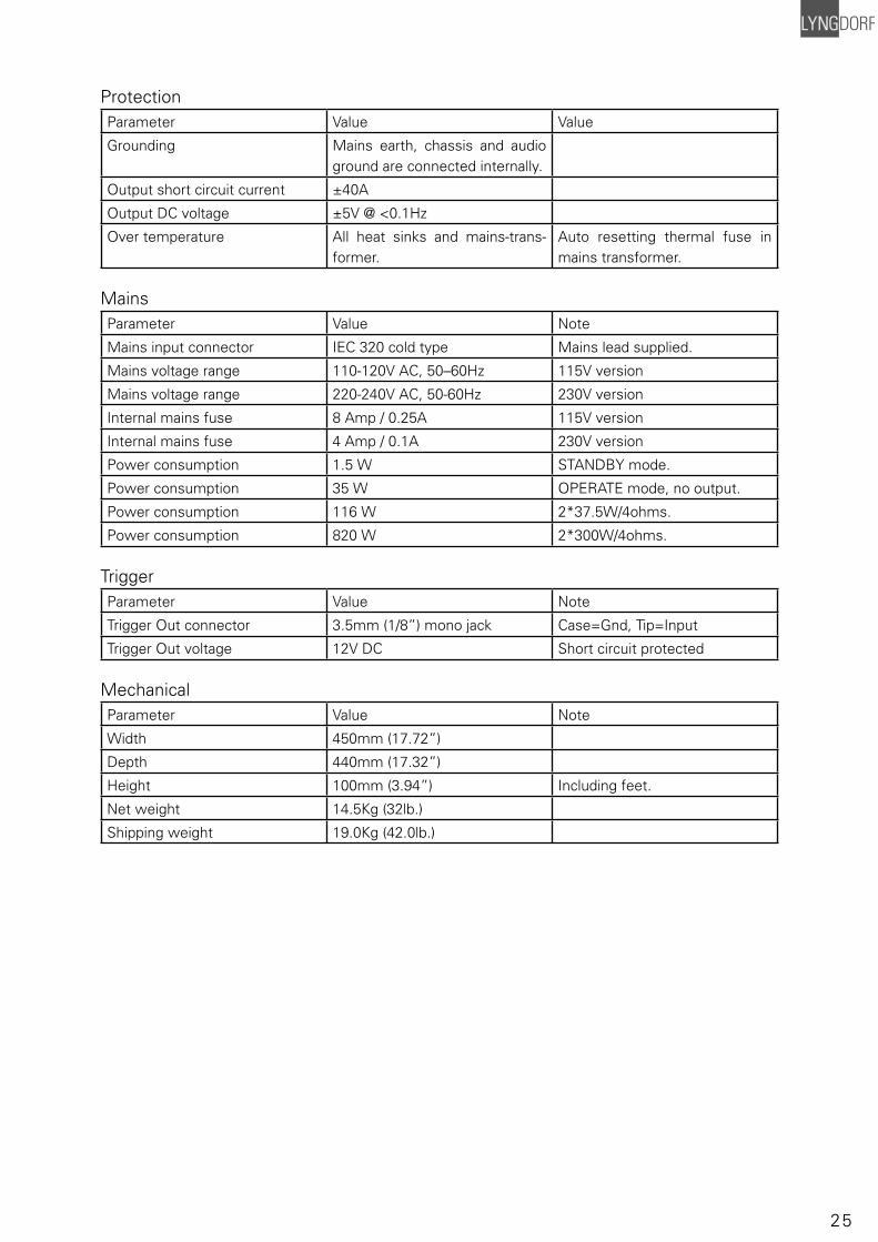
ProtectionParameter Value Value
Grounding Mains earth, chassis and audio ground are connected internally.
Output short circuit current ±40A
Output DC voltage ±5V @ <0.1Hz
Over temperature All heat sinks and mains-trans-former.
Auto resetting thermal fuse in mains transformer.
MainsParameter Value Note
Mains input connector IEC 320 cold type Mains lead supplied.
Mains voltage range 110-120V AC, 50–60Hz 115V version
Mains voltage range 220-240V AC, 50-60Hz 230V version
Internal mains fuse 8 Amp / 0.25A 115V version
Internal mains fuse 4 Amp / 0.1A 230V version
Power consumption 1.5 W STANDBY mode.
Power consumption 35 W OPERATE mode, no output.
Power consumption 116 W 2*37.5W/4ohms.
Power consumption 820 W 2*300W/4ohms.
TriggerParameter Value Note
Trigger Out connector 3.5mm (1/8”) mono jack Case=Gnd, Tip=Input
Trigger Out voltage 12V DC Short circuit protected
MechanicalParameter Value Note
Width 450mm (17.72”)
Depth 440mm (17.32”)
Height 100mm (3.94”) Including feet.
Net weight 14.5Kg (32lb.)
Shipping weight 19.0Kg (42.0lb.)
26
Technical Assistance
For latest version of control software, newest version of this document and ‘Questions and Answers’, please check the ‘Support’ section on the Lyngdorf Audio website.
If you have any problems with or questions regarding your Lyngdorf Audio product, please contact your nearest Lyngdorf Audio representative or:
Lyngdorf Audio Vaeselvej 114DK7800 SkiveDenmarkE-mail: [email protected] Web: http://www.lyngdorf.com

27

28
www.lyngdorf.com
Recommended