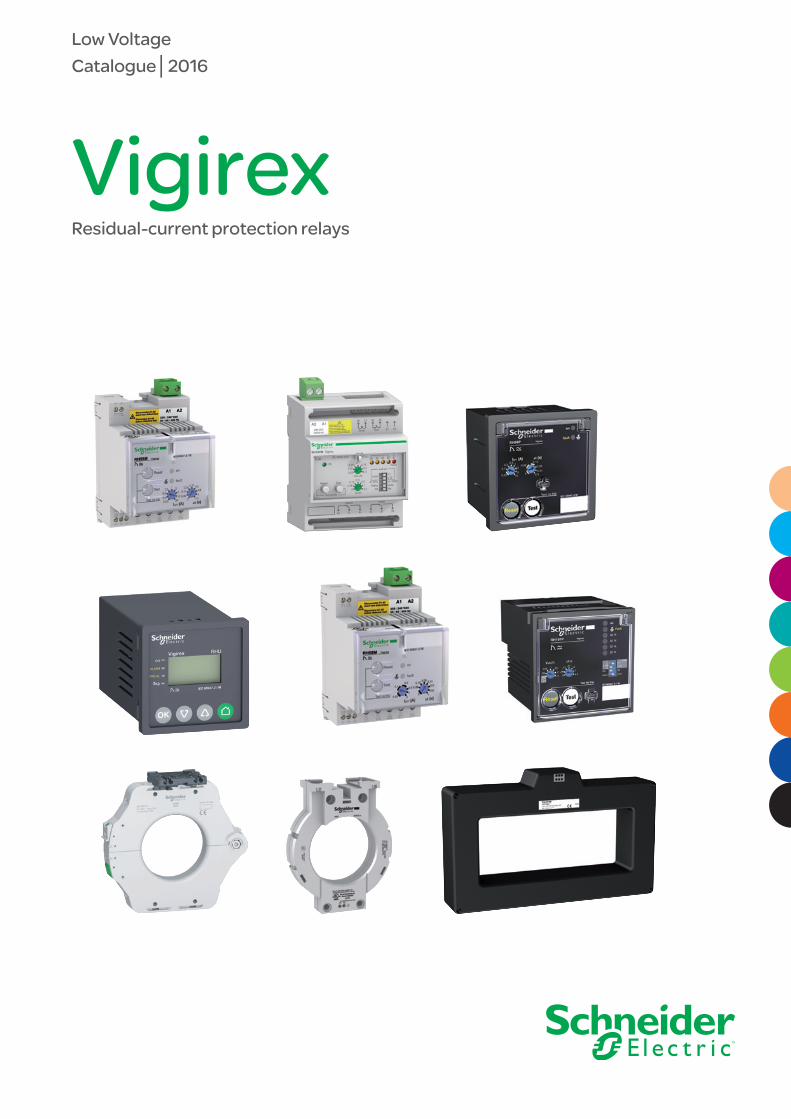
VigirexResidual-current protection relays
Low VoltageCatalogue│2016

Over 75% of Schneider Electric manufactured products awarded Green Premium eco-mark
With Green Premium, Schneider Electric commits to be transparent disclosing extensive and reliable information on environmental impacts of its products:
Green Premium is the only label allowing you to develop effectively an environmental policy and to promote it, while preserving your business efficiency.
It guarantees compliance with the most up-to-date environmental regulations, but it is more than this.
With Green Premium eco-mark, Schneider Electric helps you:• Calculate the carbon footprint of
the solutions you offer• Ensure full regulation compliance about
substances and chemical components• Deliver all appropriate information
to certify eco-design of your solutions• Easily manage products end of life,
while ensuring optimized recycling.
Green Premium, stamping the most eco-friendly products of the industry
RoHSSchneider Electric applies RoHS requirements to all its products and worldwide, even for the numerous ones which are not in the scope of the regulation. Com-pliance certificates are available for all products involved.
REAChSchneider Electric applies REACh regulation worldwide, and releases all informa-tion about presence of Substances of Very High-Concern (SVHC) in its products.
PEP: Product Environmental ProfileFor all its products, Schneider Electric publishes the most complete set of envi-ronmental data, including carbon footprint and energy consumption for each of the life cycle phases, in compliance with ISO 14025 PEPecopassport program.
EoLI: End of Life InstructionsAvailable at a click, these documents provide:
• Recyclability rates of the products
• Information to mitigate personnel hazards during dismantling and before recycling operations
• Parts identification either for re-use, or for selective treatment to mitigate envi-ronmental hazards, or incompatibility with usual recycling process.
Discover what we mean by green …. and
Check a product!
I
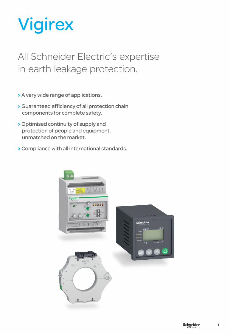
VigirexAll Schneider Electric’s expertise in earth leakage protection.
> A very wide range of applications.
> Guaranteed efficiency of all protection chain components for complete safety.
> Optimised continuity of supply and protection of people and equipment, unmatched on the market.
> Compliance with all international standards.

II
Designed for all types of distribution systems and all voltages. Wide range of auxiliary supply voltages. Wide setting and operating possibilities. Wide range of compatible sensors up to 3200 A:> A-type closed toroids: TA30, PA50, IA80, MA120, SA200 and GA300> TOA-type split toroids: TOA80 and TOA120> rectangular sensors L1, L2.
For all types of installationsVigirex relays are designed to operate with all electrical switchgear devices on the market.
Protection
Circuit monitoring
Installation monitoring
III
Compliance with international standardsThe residual-current relays comply with all the major standards worldwide, in particular those dealing with:> residual-current protection: IEC 60755 and IEC 60947-2 annex M for the protection of life and property. The Vigirex range is also certified by the independent KEMA laboratories. It has successfully passed test sequences MI/MII/MIII/MIV of standard IEC 60947-2 (annex M).> installation: IEC 60364> electromagnetic compatibility (EMC): IEC 61000> coordination of insulation: IEC 60664.
and North-American standards dealing with :> ground fault protection: UL 1053 and CSA C22.2 N° 144 (protection of equipment and property) (RH10, RH21 and RH99 up to 240 V).
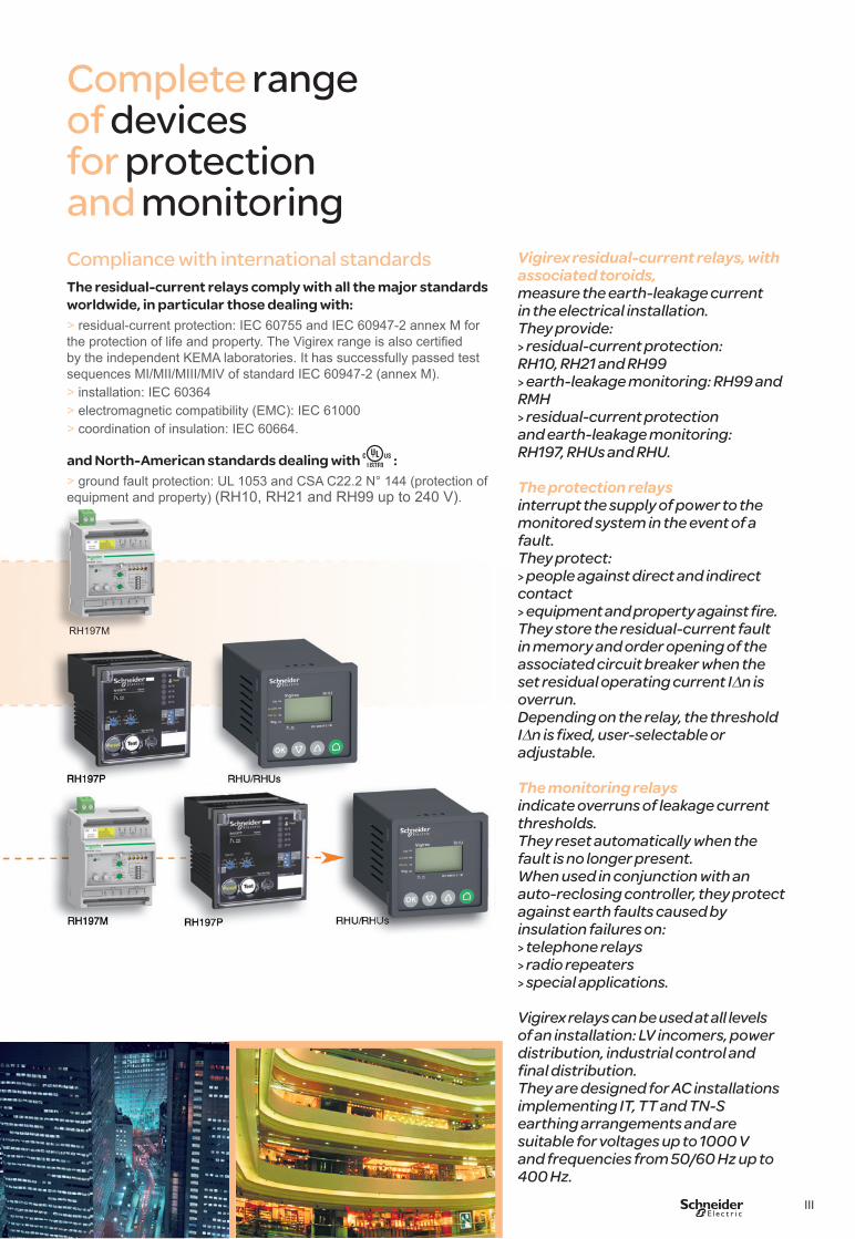
Vigirex residual-current relays, with associated toroids,measure the earth-leakage current in the electrical installation. They provide:> residual-current protection: RH10, RH21 and RH99> earth-leakage monitoring: RH99 and RMH> residual-current protection and earth-leakage monitoring: RH197, RHUs and RHU.
The protection relays interrupt the supply of power to the monitored system in the event of a fault. They protect:> people against direct and indirect contact> equipment and property against fire.They store the residual-current fault in memory and order opening of the associated circuit breaker when the set residual operating current IDn is overrun.Depending on the relay, the threshold IDn is fixed, user-selectable or adjustable.
The monitoring relays indicate overruns of leakage current thresholds.They reset automatically when the fault is no longer present. When used in conjunction with an auto-reclosing controller, they protect against earth faults caused by insulation failures on: > telephone relays> radio repeaters> special applications.
Vigirex relays can be used at all levels of an installation: LV incomers, power distribution, industrial control and final distribution. They are designed for AC installations implementing IT, TT and TN-S earthing arrangements and are suitable for voltages up to 1000 V and frequencies from 50/60 Hz up to 400 Hz.
Complete range of devices for protection and monitoring
RH197M

IV
A three-step process
Absolute protection of life and propertyThe overrun of leakage current thresholds may represent a threat to life and property if it is not immediately located. Through permanent monitoring of this overrun, the Vigirex range makes the protection efficient.
Class
2front panel insulationClass II insulated front panel certification for the entire range as per standards IEC/EN 60664-1 and NFC 15-100.
1
Maximum safetyVigirex residual current devices (RCDs) with appropriate settings provide effective protection of life and property. The characteristics of the relay/toroid combination ensure reliable measurements.
Operation guaranteed in less than 40 msSchneider Electric guarantees the safe clearing of faults by Vigirex relays set to 30 mA and combined with any of its circuit breakers rated up to 630 A.
Overvoltage category IVThe reinforced insulation of Vigirex relays (overvoltage category IV, i.e. the most severe category) makes direct connection possible at the head of the installation or on the upstream busbars without any additional galvanic isolation.
Continuous self-monitoringVigirex relays continuously monitor the power supply, relay/toroid link and internal electronics. Failure of the detection circuit is signalled and may be used to trip the circuit breaker. The LEDs on the front panel can also be used to check operation at any time.
Settings protected by a lead-sealable coverAccess to settings can be protected by a cover with a lead seal. The test and reset buttons remain accessible on the front panel of the relay.
Detection
with associated toroid
Alarm
with the Vigirex relay

V
2 3
Optimum continuity of serviceThe entire range offers numerous settings possibilities that may be used to create many discrimination levels, from the incomer to the final output circuits. With Vigirex, unnecessary downtime is eliminated.
Diagnosis of installation faultsThe indication relays are used to:> monitor electrical insulation faults,> prevent outages,> initiate preventive maintenance.
Minimise outagesCorrect setting of the residual current devices (RCDs) ensures total discrimination for insulation faults in the installation, i.e. only the faulty section is shut down. Elimination of most cases of RCD nuisance tripping ensures both safety and continuity of service, two indispensable features for users.
Reduced tripping toleranceVigirex relays trip between 0.8 et 1 x IDn, thus increasing immunity to nuisance tripping by 60% compared to the earth leakage protection requirements of standard IEC 60947-2.During circuit energisation, the inverse-time tripping curve makes it possible to avoid nuisance tripping of the earth leakage protection system by false zero phase sequence currents caused by:> high transient currents of certain loads (e.g. motors, LV / LV transformers),> the charging of capacitances between active conductors and earth.
Frequency filtering and true RMS measurementFrequency filtering by Vigirex residual current relays ensures maximum protection against insulation faults and a particularly high level of continuity of service.Frequency converters such as variable speed drives generate high levels of high-frequency leakage currents. During normal operation, these leakage currents are not a danger to users. The residual current relay measures all types of signals and calculates the true RMS value weighted to allow for frequency filtering.
Test and resetTo monitor the protection or indication system, the relay includes a complete test function with or without tripping of the protection device.Moreover, the purpose of the test is to check:> the output contacts,> the display (RHU/RHUs and RMH),> the LEDs, > the internal electronics.
Centralised testOne or more relays can be tested remotely, with or without tripping the associated breaking device.
Protection with the circuit breaker
VI
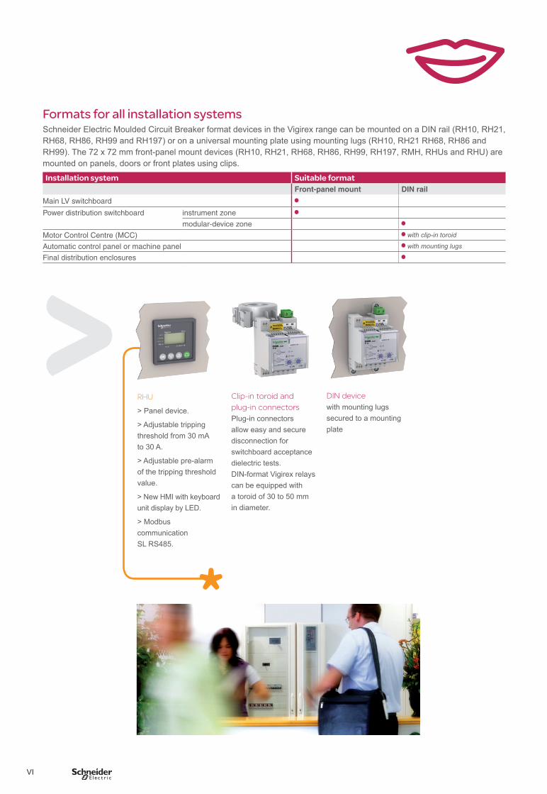
Formats for all installation systemsSchneider Electric Moulded Circuit Breaker format devices in the Vigirex range can be mounted on a DIN rail (RH10, RH21, RH68, RH86, RH99 and RH197) or on a universal mounting plate using mounting lugs (RH10, RH21 RH68, RH86 and RH99). The 72 x 72 mm front-panel mount devices (RH10, RH21, RH68, RH86, RH99, RH197, RMH, RHUs and RHU) are mounted on panels, doors or front plates using clips.
Installation system Suitable formatFront-panel mount DIN rail
Main LV switchboard
Power distribution switchboard instrument zone
modular-device zone
Motor Control Centre (MCC) with clip-in toroid
Automatic control panel or machine panel with mounting lugs
Final distribution enclosures
RHU
> Panel device.
> Adjustable tripping threshold from 30 mA to 30 A.
> Adjustable pre-alarm of the tripping threshold value.
> New HMI with keyboard unit display by LED.
> Modbus communication SL RS485.
DIN device with mounting lugs secured to a mounting plate
Clip-in toroid and plug-in connectors Plug-in connectors allow easy and secure disconnection for switchboard acceptance dielectric tests. DIN-format Vigirex relays can be equipped with a toroid of 30 to 50 mm in diameter.
VII
Certified quality: ISO 9001: 2000Our efforts are based on a Quality Management System to enhance the effectiveness of our processes, the goal being to ensure continuous improvement in compliance with standard ISO 9001: 2000.Our quality objectives are built into our products right from the design phase.We are committed to implementing the five key points of our quality policy:> measurement of customer satisfaction> solidly built products> control of the manufacturing process> management of development projects> commitment of all those involved.
CE marking The CE marking, created by European legislation, is designed to provide assurance that the product is not dangerous, non-polluting and immune to electromagnetic disturbances (EMC directive).
A never-ending commitmentEnvironmental protection, a reduction in raw materials consumed, controlled energy consumption and product recycling are taken into account right from the beginning of the design phase and on all the Group’s production sites.During design, Schneider Electric uses high-performance tools to assess and reduce the impact of its products on the environment throughout their life cycles.EIME (Environmental Information and Management Explorer) CAD software assists designers in selecting materials and designing products.
Production units certified ISO 14001 The production unit benefits from the environmental-management system set up on each ISO 14001 certified site to guarantee continuous progress.
Easy sorting and recycling The plastics used are marked to ensure easy identification for sorting and recycling. If burned, no polluting substances are released.

VIII
Machines Buildings Retail
HotelsHospitals Airports Electrical energy
Industry Mining Refineries Off-shore
> Designed for all types of distribution systems and all voltages
> Wide range of auxiliary supply voltages
> Wide setting and operating possibilities
> Wide range of compatible sensors up to 3200 A
> Compatible with all electrical switchgear devices on the market
1
Vigirex General contents
A-1
B-1
C-1
D-1
E-1
F-1
Installation recommendations
Functions and characteristics
Dimensions and connections
Wiring diagrams
Additional characteristics
Catalogue numbers
2
A-1
B-1
C-1
D-1
E-1
F-1
G-1

A-1
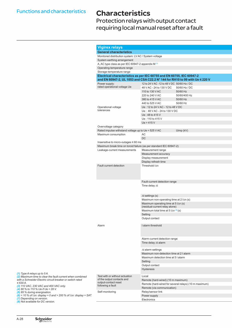
Vigirex Functions and characteristics
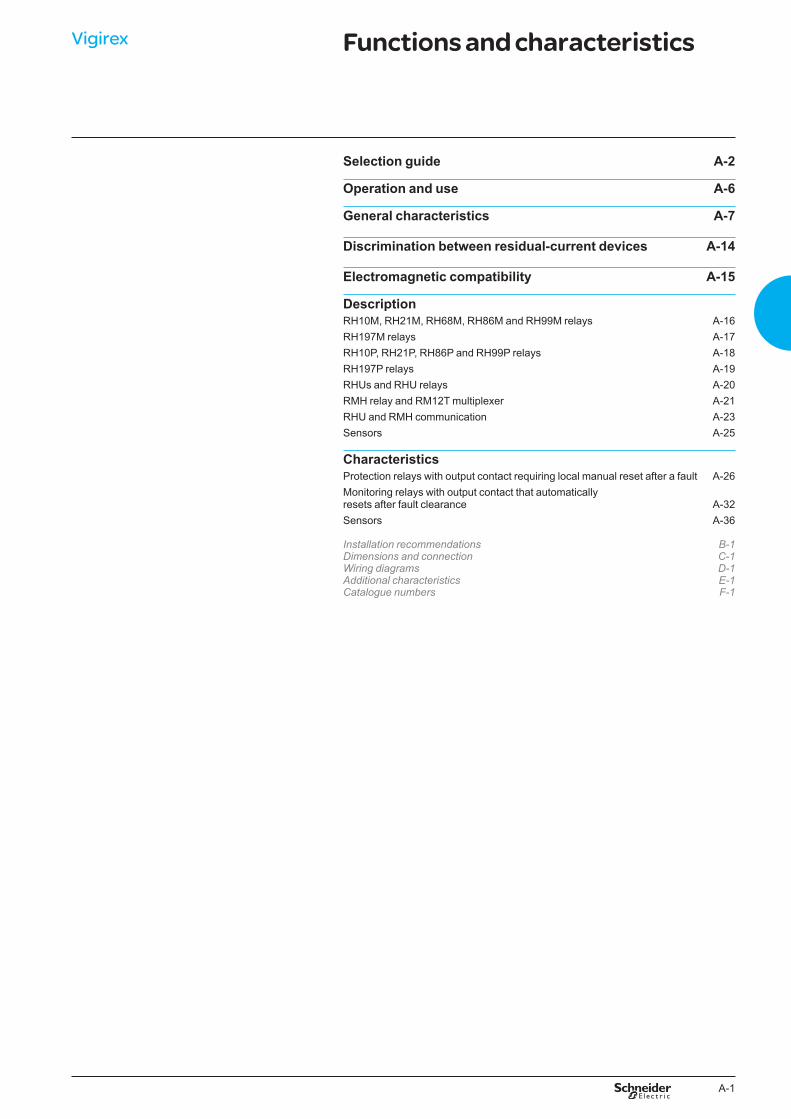
Selection guide A-2
Operation and use A-6
General characteristics A-7
Discrimination between residual-current devices A-14
Electromagnetic compatibility A-15
Description RH10M, RH21M, RH68M, RH86M and RH99M relays A-16RH197M relays A-17RH10P, RH21P, RH86P and RH99P relays A-18RH197P relays A-19RHUs and RHU relays A-20RMH relay and RM12T multiplexer A-21RHU and RMH communication A-23Sensors A-25
Characteristics Protection relays with output contact requiring local manual reset after a fault A-26Monitoring relays with output contact that automatically resets after fault clearance A-32Sensors A-36
Installation recommendations B-1Dimensions and connection C-1Wiring diagrams D-1Additional characteristics E-1Catalogue numbers F-1

A-2
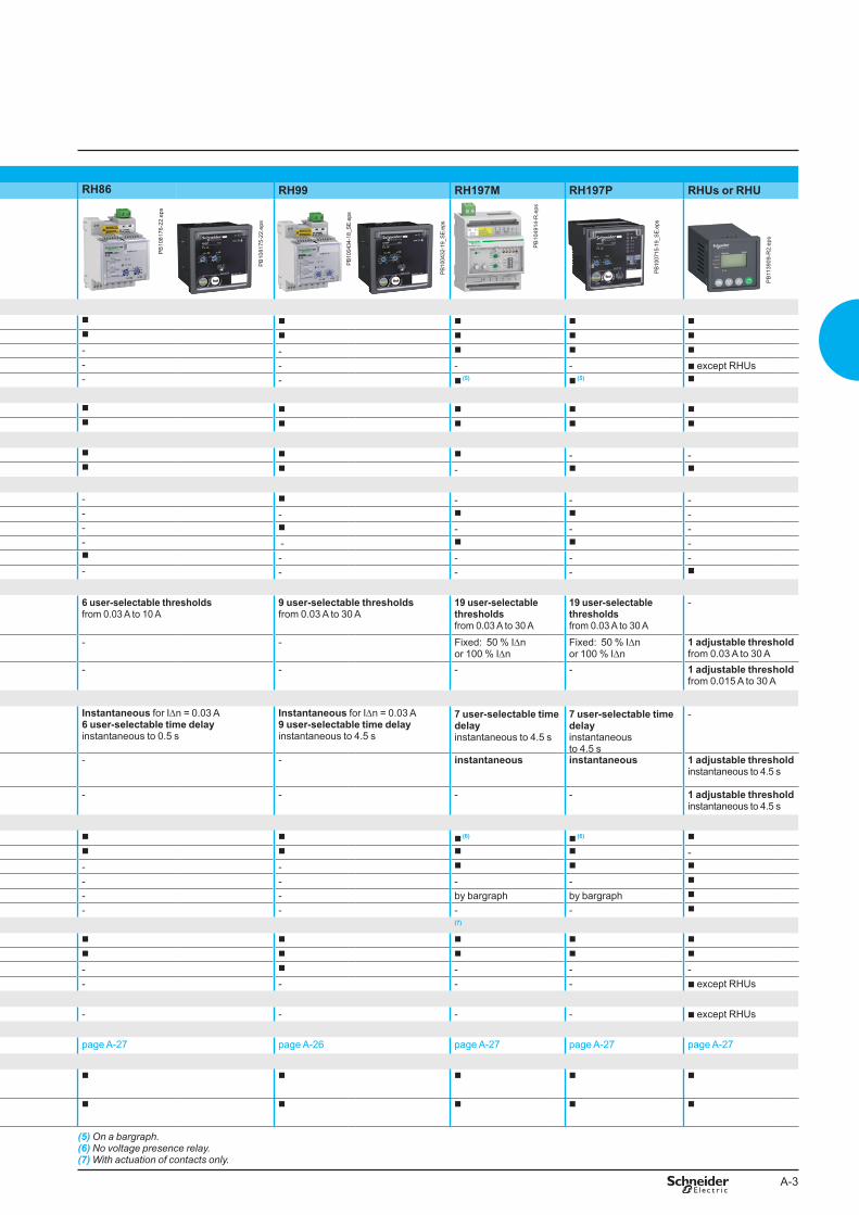
Protection relays (2)
RH10 RH21 RH68 RH86 RH99 RH197M RH197P RHUs or RHUAll Vigirex products are type A (1) devices, also covering the requirements of type AC devices.
PB10
0435
-18_
SE.e
ps
PB10
0430
-19_
SE.e
ps
PB10
0433
-18_
SE.e
ps
PB10
0431
-19_
SE.e
ps
PB
1081
77-2
2.ep
s
PB
1081
76-2
2.ep
s
PB
1081
75-2
2.ep
s
PB10
0434
-18_
SE.e
ps
PB10
0432
-19_
SE.e
ps
PB
1049
14-R
.eps
PB10
0715
-19_
SE.e
ps
PB
1139
09-R
2.ep
s
FunctionsProtection b b b b b b b b
Local indications b b b b b b b b
Remote indications (hard-wired) - - - - - b b b
Remote indications (via communication) - - - - - - - b except RHUsDisplay of measurements - - - - - b (5) b (5) b
WiringOptimum continuity of service b b b b b b b b
Optimum safety (failsafe) b b b b b b b b
MountingDIN rail b b b b b b - -Front-panel mount b b - b b - b b
Rated operational voltage1 DC voltage range from 12 to 48 V b b - - b - - -1 DC voltage range from 24 to 130 V - - - - - b b -5 AC voltage ranges from 12 to 525 V b b - - b - - -4 AC voltage ranges from 48 to 415 V - - - - - b b -1 AC voltage range from 220 to 240 V - - b b - - - -2 AC voltage ranges from 110 to 240 V - - - - - - - b
ThresholdsFault (IDn) 1 fixed instantaneous threshold
choose from 0.03 A to 1 A2 user-selectable thresholds 0.03 A or 0.3 A
6 user-selectable thresholds from 0.03 A to 3 A
6 user-selectable thresholds from 0.03 A to 10 A
9 user-selectable thresholds from 0.03 A to 30 A
19 user-selectable thresholds from 0.03 A to 30 A
19 user-selectable thresholds from 0.03 A to 30 A
-
Alarm - - - - - Fixed: 50 % IDnor 100 % IDn
Fixed: 50 % IDnor 100 % IDn
1 adjustable thresholdfrom 0.03 A to 30 A
Pre-alarm - - - - - - - 1 adjustable threshold from 0.015 A to 30 A
Time delayFault Instantaneous 1 user-selectable time delay
instantaneous or 0.06 s for IDn = 0.3 A
Instantaneous for IDn = 0.03 A 8 user-selectable time delay instantaneous to 1 s
Instantaneous for IDn = 0.03 A 6 user-selectable time delay instantaneous to 0.5 s
Instantaneous for IDn = 0.03 A 9 user-selectable time delay instantaneous to 4.5 s
7 user-selectable time delayinstantaneous to 4.5 s
7 user-selectable time delayinstantaneous to 4.5 s
-
Alarm - - - - - instantaneous instantaneous 1 adjustable threshold instantaneous to 4.5 s
Pre-alarm - - - - - - - 1 adjustable threshold instantaneous to 4.5 s
Display and indicationsVoltage presence (LED and/or relay) (3) b b b b b b (6) b (6) b
Threshold overrun fault (LED) b b b b b b b -alarm (LED and relay) - - - - - b b b
pre-alarm (LED and relay) - - - - - - - b
Leakage current (digital) - - - - - by bargraph by bargraph b
Settings (digital) - - - - - - - b
Test with or without actuation of output contacts (7)
Local b b b b b b b b
Remote (hard-wired) b b b b b b b b
Remote (hard-wired for several relays) b b - - b - - -Remote (via communication) - - - - - - - b except RHUsCommunicationSuitable for supervision - - - - - - - b except RHUsCharacteristics
page A-26 page A-26 page A-27 page A-27 page A-26 page A-27 page A-27 page A-27
SensorsSchneider Electric A and TOA toroids (4)
up to 630 A b b b b b b b b
Schneider Electric rectangular sensors
up to 3200 A b b b b b b b b
(1) Type A relay up to IDn = 5 A.(2) Relay with output contact requiring local, manual reset after fault clearance.
(3) Depending on the type of wiring (optimum continuity of service or optimum safety).(4) See characteristics page A-��page A-��.
(5) On a bargraph.(6) No voltage presence relay.(7) With actuation of contacts only.
Functions and characteristics Selection guide
A-3
Protection relays (2)
RH10 RH21 RH68 RH86 RH99 RH197M RH197P RHUs or RHUAll Vigirex products are type A (1) devices, also covering the requirements of type AC devices.
PB10
0435
-18_
SE.e
ps
PB10
0430
-19_
SE.e
ps
PB10
0433
-18_
SE.e
ps
PB10
0431
-19_
SE.e
ps
PB
1081
77-2
2.ep
s
PB
1081
76-2
2.ep
s
PB
1081
75-2
2.ep
s
PB10
0434
-18_
SE.e
ps
PB10
0432
-19_
SE.e
ps
PB
1049
14-R
.eps
PB10
0715
-19_
SE.e
ps
PB
1139
09-R
2.ep
s
FunctionsProtection b b b b b b b b
Local indications b b b b b b b b
Remote indications (hard-wired) - - - - - b b b
Remote indications (via communication) - - - - - - - b except RHUsDisplay of measurements - - - - - b (5) b (5) b
WiringOptimum continuity of service b b b b b b b b
Optimum safety (failsafe) b b b b b b b b
MountingDIN rail b b b b b b - -Front-panel mount b b - b b - b b
Rated operational voltage1 DC voltage range from 12 to 48 V b b - - b - - -1 DC voltage range from 24 to 130 V - - - - - b b -5 AC voltage ranges from 12 to 525 V b b - - b - - -4 AC voltage ranges from 48 to 415 V - - - - - b b -1 AC voltage range from 220 to 240 V - - b b - - - -2 AC voltage ranges from 110 to 240 V - - - - - - - b
ThresholdsFault (IDn) 1 fixed instantaneous threshold
choose from 0.03 A to 1 A2 user-selectable thresholds 0.03 A or 0.3 A
6 user-selectable thresholds from 0.03 A to 3 A
6 user-selectable thresholds from 0.03 A to 10 A
9 user-selectable thresholds from 0.03 A to 30 A
19 user-selectable thresholds from 0.03 A to 30 A
19 user-selectable thresholds from 0.03 A to 30 A
-
Alarm - - - - - Fixed: 50 % IDnor 100 % IDn
Fixed: 50 % IDnor 100 % IDn
1 adjustable thresholdfrom 0.03 A to 30 A
Pre-alarm - - - - - - - 1 adjustable threshold from 0.015 A to 30 A
Time delayFault Instantaneous 1 user-selectable time delay
instantaneous or 0.06 s for IDn = 0.3 A
Instantaneous for IDn = 0.03 A 8 user-selectable time delay instantaneous to 1 s
Instantaneous for IDn = 0.03 A 6 user-selectable time delay instantaneous to 0.5 s
Instantaneous for IDn = 0.03 A 9 user-selectable time delay instantaneous to 4.5 s
7 user-selectable time delayinstantaneous to 4.5 s
7 user-selectable time delayinstantaneous to 4.5 s
-
Alarm - - - - - instantaneous instantaneous 1 adjustable threshold instantaneous to 4.5 s
Pre-alarm - - - - - - - 1 adjustable threshold instantaneous to 4.5 s
Display and indicationsVoltage presence (LED and/or relay) (3) b b b b b b (6) b (6) b
Threshold overrun fault (LED) b b b b b b b -alarm (LED and relay) - - - - - b b b
pre-alarm (LED and relay) - - - - - - - b
Leakage current (digital) - - - - - by bargraph by bargraph b
Settings (digital) - - - - - - - b
Test with or without actuation of output contacts (7)
Local b b b b b b b b
Remote (hard-wired) b b b b b b b b
Remote (hard-wired for several relays) b b - - b - - -Remote (via communication) - - - - - - - b except RHUsCommunicationSuitable for supervision - - - - - - - b except RHUsCharacteristics
page A-26 page A-26 page A-27 page A-27 page A-26 page A-27 page A-27 page A-27
SensorsSchneider Electric A and TOA toroids (4)
up to 630 A b b b b b b b b
Schneider Electric rectangular sensors
up to 3200 A b b b b b b b b
(1) Type A relay up to IDn = 5 A.(2) Relay with output contact requiring local, manual reset after fault clearance.
(3) Depending on the type of wiring (optimum continuity of service or optimum safety).(4) See characteristics page A-��page A-��.
(5) On a bargraph.(6) No voltage presence relay.(7) With actuation of contacts only.
A-4
Functions and characteristics Selection guide
Monitoring relays (2)
RH99 RH197M RH197P RHUs or RHU RMHAll Vigirex products are type A (1) devices, also covering the requirements of type AC devices.
PB10
0429
-18_
SE.e
ps
PB10
0432
-19_
SE.e
ps
PB
1049
14-R
.eps
PB10
0715
-19_
SE.e
ps
PB
1139
09-R
2.ep
s
PB
1139
09-R
2.ep
s
+
0594
85-2
0_S
E.e
ps
(3)
FunctionsProtection - b b - -Local indications b b b b b
Remote indications (hard-wired) b b b b b
Remote indications (via communication) - - - b except RHUs b
Display of measurements - b (5) b (5) - b 12 measurement channels (4)
WiringOptimum continuity of service - b b - -Optimum safety (failsafe) - b b - -MountingDIN rail b b - - -Front-panel mount b - b b b
Rated operational voltage1 DC voltage range from 12 to 48 V b - - - -1 DC voltage range from 24 to 130 V - b b - -5 AC voltage ranges from 12 to 525 V b - - - -4 AC voltage ranges from 48 to 415 V - b b - -1 AC voltage range from 220 to 240 V - - - - -2 AC voltage ranges from 110 to 240 V - - - b b
ThresholdsFault (IDn) - 19 user-selectable thresholds
from 0.03 A to 30 A19 user-selectable thresholds from 0.03 A to 30 A
- -
Alarm 9 user-selectable thresholds from 0.03 A to 30 A
Fixed: 50 % IDnor 100 % IDn
Fixed: 50 % IDnor 100 % IDn
1 adjustable threshold/channelfrom 0.03 A to 30 A
1 adjustable threshold/channelfrom 0.03 A to 30 A
Pre-alarm - - - 1 adjustable threshold/channelfrom 0.015 A to 30 A
1 adjustable threshold/channelfrom 0.015 A to 30 A
Time delayFault - 7 user-selectable time delay
instantaneous to 4.5 s7 user-selectable time delayinstantaneous to 4.5 s
- -
Alarm 9 user-selectable time delay instantaneous to 4.5 s
instantaneous instantaneous 1 adjustable threshold/channel instantaneous to 5 s
1 adjustable threshold/channel instantaneous to 5 s
Pre-alarm - - - 1 adjustable threshold/channel instantaneous to 5 s
1 adjustable threshold/channel instantaneous to 5 s
Display and indicationsVoltage presence (LED and/or relay) (5) b b (7) b (7) b b
Threshold overrun fault (LED) - b b - -alarm (LED and relay) b b b b b
pre-alarm (LED and relay) - - - b b
Leakage current (digital) - by bargraph by bargraph b b
Settings (digital) - - - b b
Test with or without actuation of output contacts (8)
Local b b b b b
Remote (hard-wired) b b b b -Remote (hard-wired for several relays) b - - - -Remote (via communication) - - - b except RHUs b
CommunicationSuitable for supervision - - - b except RHUs b
Characteristicspage A-35 page A-27 page A-27 page A-35 page A-35
Sensors Schneider Electric A and TOA toroids (6)
up to 630 A b b b b b
Schneider Electric rectangular sensors
up to 3200 A b b b b b
(1) Type A relay up to IDn = 5 A.(2) Relay with output contact that automatically resets after fault clearance. (3) Mandatory with an RMH (multiplexing for the 12 toroids).(4) Mandatory with an RM12T (multiplexing for the 12 toroids).
(5) Depending on the type of wiring (optimum continuity of service or optimum safety).(6) See characteristics page A-��page A-��.(7) No voltage presence relay.(8) With actuation of contacts only.

A-5
Monitoring relays (2)
RH99 RH197M RH197P RHUs or RHU RMHAll Vigirex products are type A (1) devices, also covering the requirements of type AC devices.
PB10
0429
-18_
SE.e
ps
PB10
0432
-19_
SE.e
ps
PB
1049
14-R
.eps
PB10
0715
-19_
SE.e
ps
PB
1139
09-R
2.ep
s
PB
1139
09-R
2.ep
s
+
0594
85-2
0_S
E.e
ps
(3)
FunctionsProtection - b b - -Local indications b b b b b
Remote indications (hard-wired) b b b b b
Remote indications (via communication) - - - b except RHUs b
Display of measurements - b (5) b (5) - b 12 measurement channels (4)
WiringOptimum continuity of service - b b - -Optimum safety (failsafe) - b b - -MountingDIN rail b b - - -Front-panel mount b - b b b
Rated operational voltage1 DC voltage range from 12 to 48 V b - - - -1 DC voltage range from 24 to 130 V - b b - -5 AC voltage ranges from 12 to 525 V b - - - -4 AC voltage ranges from 48 to 415 V - b b - -1 AC voltage range from 220 to 240 V - - - - -2 AC voltage ranges from 110 to 240 V - - - b b
ThresholdsFault (IDn) - 19 user-selectable thresholds
from 0.03 A to 30 A19 user-selectable thresholds from 0.03 A to 30 A
- -
Alarm 9 user-selectable thresholds from 0.03 A to 30 A
Fixed: 50 % IDnor 100 % IDn
Fixed: 50 % IDnor 100 % IDn
1 adjustable threshold/channelfrom 0.03 A to 30 A
1 adjustable threshold/channelfrom 0.03 A to 30 A
Pre-alarm - - - 1 adjustable threshold/channelfrom 0.015 A to 30 A
1 adjustable threshold/channelfrom 0.015 A to 30 A
Time delayFault - 7 user-selectable time delay
instantaneous to 4.5 s7 user-selectable time delayinstantaneous to 4.5 s
- -
Alarm 9 user-selectable time delay instantaneous to 4.5 s
instantaneous instantaneous 1 adjustable threshold/channel instantaneous to 5 s
1 adjustable threshold/channel instantaneous to 5 s
Pre-alarm - - - 1 adjustable threshold/channel instantaneous to 5 s
1 adjustable threshold/channel instantaneous to 5 s
Display and indicationsVoltage presence (LED and/or relay) (5) b b (7) b (7) b b
Threshold overrun fault (LED) - b b - -alarm (LED and relay) b b b b b
pre-alarm (LED and relay) - - - b b
Leakage current (digital) - by bargraph by bargraph b b
Settings (digital) - - - b b
Test with or without actuation of output contacts (8)
Local b b b b b
Remote (hard-wired) b b b b -Remote (hard-wired for several relays) b - - - -Remote (via communication) - - - b except RHUs b
CommunicationSuitable for supervision - - - b except RHUs b
Characteristicspage A-35 page A-27 page A-27 page A-35 page A-35
Sensors Schneider Electric A and TOA toroids (6)
up to 630 A b b b b b
Schneider Electric rectangular sensors
up to 3200 A b b b b b
(1) Type A relay up to IDn = 5 A.(2) Relay with output contact that automatically resets after fault clearance. (3) Mandatory with an RMH (multiplexing for the 12 toroids).(4) Mandatory with an RM12T (multiplexing for the 12 toroids).
(5) Depending on the type of wiring (optimum continuity of service or optimum safety).(6) See characteristics page A-��page A-��.(7) No voltage presence relay.(8) With actuation of contacts only.
A-6
I n (A)
t (s)
RH99MVigirex
DB
1259
80.e
ps FunctionVigirex relays measure the earth-leakage current in an electrical installation via their associated toroids.Vigirex relays may be used for:
b residual-current protection (RH10, RH21, RH68, RH86, RH99) b earth-leakage monitoring (RMH or RH99) b residual-current protection and earth-leakage monitoring (RH197, RHUs
and RHU).
Residual-current protection relayProtection relays control the interruption of the supply of power to the monitored systems to protect:
b people against indirect contact and, in addition, against direct contact b property against fire hazards b motors.
A relay trips the associated circuit breaker when the set residual operating current IDn is overrun. Depending on the relay, the threshold IDn can be fixed, user-selectable or adjustable and the overrun can be signalled by a digital display of the measured current or a LED. The leakage current is displayed:
b for the RH197, on a bargraph made up of 4 LEDs indicating levels corresponding to 20, 30, 40 and 50 % of IDn
b for the RHUs and RHU, by digital display of the value of the leakage current.Circuit breaker tripping can be either instantaneous or delayed. On some relays, it is possible to adjust the time delay.The protection relays store the residual-current fault in memory. Once the fault has been cleared and the output contact has been manually reset, the relay can be used again.
Earth-leakage monitoring relaysThese relays may be used to monitor drops in electrical insulation due to ageing of cables or extensions in the installation.Continuous measurement of leakage currents makes it possible to plan preventive maintenance on the faulty circuits. An increase in the leakage currents may lead to a complete shutdown of the installation.The control signal is issued by the relay when the residual-current operating threshold is overrun.Depending on the relay, the threshold can be adjustable or user-selectable and the overrun can be signalled via a LED, a bargraph or a digital display of the measured current.The leakage current is displayed:
b for the RH197, on a bargraph made up of 4 LEDs indicating levels corresponding to 20, 30, 40 and 50 % of IDn
b for the RMH, by digital display of the value of the leakage current. The control signal can be either instantaneous or delayed. On some relays, it is possible to adjust the time delay.Earth-leakage monitoring relays do not store the residual-current fault in memory and their output contact is automatically reset when the fault is cleared.When used in conjunction with a Acti 9 ATm3 or ATm7 auto-reclosing controller (Schneider Electric catalogue numbers 18306 and 18307 respectively), they protect against earth faults due to insulation failures. Typical applications include telephone relay and radio repeater stations. In the event of a transient fault, this system can be used to automatically restore the supply of electrical power to an unattended station, thereby increasing availability and continuity of service.
UseVigirex relays may be used for protection and maintenance at all levels in the installation. Depending on the relays, they may be used in TT, IT or TNS low-voltage AC installations for voltages up to 1000 V and frequencies from 50/60 Hz up to 400 Hz.Vigirex protection relays are suitable for use with all electrical switchgear devices available on the market.
IDn (A): residual operating-current setting(the relay operates for a fault current u IDn).Schneider Electric guarantees non-operation for all fault currents < 0.8 IDn.Dt (s): minimum non-operating time.
Functions and characteristics Operation and use
A-7
DB
4035
71.e
ps Compliance with standardsVigirex relays are designed to comply with the following standards:
b IEC/EN 60755: general rules for residual-current protection devices b IEC/EN 60947-2 annex M: low-voltage switchgear and controlgear, part 2 (circuit
breakers) b IEC/EN 60947-5-1: low-voltage switchgear and controlgear, part 5-1
(electromechanical devices) b IEC/EN 61000-4-2: electrostatic-discharge immunity test b IEC/EN 61000-4-3: radiated, radio-frequency, electromagnetic-field immunity test b IEC/EN 61000-4-4: electrical fast transient/burst immunity test b IEC/EN 61000-4-5: surge immunity test b IEC/EN 61000-4-6: immunity to conducted disturbances, induced by radio-
frequency fields b CISPR 11: limits and methods of measurement of electromagnetic disturbance
characteristics of industrial, scientific and medical (ISM) radiofrequency equipment b mandatory for CE marking: v EN 61000-6-2: immunity to industrial environments v EN 50081-1: emissions for commercial and residential environments b IEC/EN 60664-1: insulation coordination for equipment within low-voltage
systems, part 1 b EN 50102: degrees of protection provided by electrical enclosures against external
mechanical impact b IEC 60364 and NF C 15100: installation rules for low-voltage electrical distribution b UL 1053 and CSA 22.2 No. 144: relays RH10, RH21 and RH99 up to and including
220/240 V comply with these standards.
Ground fault sensing and relaying equipment UL 1053 and CSA 22.2 No. 144 for North American and North American influenced marketsThe basic standard used to investigate products in this category is UL1053 “Ground-Fault Sensing and Relaying Equipment”.The Listing Mark of Underwriters Laboratories Inc. on the products is the only method provided by UL to identify products manufactured under its Listing and Follow Up Service.The Listing Mark for these products includes the name and/or symbol of Underwriters Laboratories Inc. (as illustrated on the label) together with the word “LISTED”, a control number and the following product name “Ground Fault Sensing and Relaying Equipment”.This category covers ground fault current sensing devices, relaying equipment, or combinations of ground fault current sensing devices and relaying equipment which will operate to cause a disconnecting means to function at predetermined values of ground fault current in accordance with the National Electrical Code, ANSI/NFPA70.The RH99, RH21 and RH10 (M and P) ground fault relays are control powered ground-fault protection devices used to protect an electrical distribution system from ground faults. The relay receives input from sensors, processes the information and if necessary closes output contacts which will cause the associated protection device to trip.The product is a class 1 combination ground fault current sensor and relay. This equipment is intended to operate devices with shunt trip coils such as moulded case circuit breakers, moulded case switches and the like, which constitute the disconnecting means, by opening all ungrounded conductors at predetermined values of ground fault current.This product is designed to protect circuits of not more than 600 V AC, 50/60 Hz only.The relay should be marked with the following electrical ratings, for the two types M and P:
b type M: DIN format (Acti 9 type fast mounting or screw mounting) b type P: front-panel mount (on panel, door, etc.) b ratings: v fixed IDn threshold (a number of choices) and no time delay (instantaneous) or v selectable IDn threshold from 0.03 to 30 A and user-selectable time delay
from 0 to 4.5 s (see settings on pages A-26 to A-35) b input voltages: v AC: 20 to 24 V AC, 48 V AC, 110 to 130V AC or 220 to 240 V AC, 50/60 Hz, or v DC: 12 to 48 V DC b maximum consumption: 4 W.
DB
1010
79.e
ps
The mark indicates that the product meets both US and Canadian safety requirements.
General characteristics
A-8
Functions and characteristicsPB
1004
30-3
6_SE
.eps Environmental withstand capacity
Vigirex relays meet the environmental requirements contained in the following standards:
b IEC/EN 60068-2-30: damp heat, equipment not operating; relative humidity 95 % at 55 °C (hot and humid climate)
b IEC/EN 60068-2-52: salt mist; KB test severity level 2 b IEC/EN 60068-2-56: damp heat, equipment operating; 48 h, environment
category C2.They may consequently be used in all parts of the world.
Degree of pollutionVigirex relays are suitable for operation in the most severe industrial environments. They meet the requirements of degree of pollution 3 as per standard IEC/EN 60664-1 and IEC/EN 60947-1 for low-voltage switchgear and controlgear.
Ambient temperatureVigirex relays are designed for use in ambient temperatures from -35 °C to +70 °C. Relays equipped with a digital display (RHU, RHUs, RMH) or bargraph (RH197) are limited to -25 °C to +55 °C.Start-up should be carried out within the temperature range indicated above.The temperature range for device storage, in the original packing, is:
b between -55 °C and +85 °C for Vigirex RH10 to RH99 b between -40 °C and +85 °C for Vigirex RH197, RHUs, RHU and RMH.
Reinforced insulation for direct connection to upstream distribution systemThe reinforced insulation of Vigirex relays (overvoltage category IV, the most severe) makes possible, without any additional galvanic isolation:
b direct connection of the relay power supply to the upstream circuit (connection upstream of an LV incoming device such as a Masterpact circuit breaker, for example)
b direct connection to the upstream busbars. Insulation classAll Vigirex relays, whether DIN or front-panel mount format, have class II insulated fronts as per standards IEC/EN 60664-1 and NF C 15100.The communication outputs on the RHU and RMH relays are also class II.
Degree of protectionAccording to standards EN 60529 (IP degree of protection) and EN 50102 (IK external mechanical impact protection), the devices are rated IP40 and IK07 for the front face through a door or on a front plate, IP30 for the other faces and IP20 for connections.
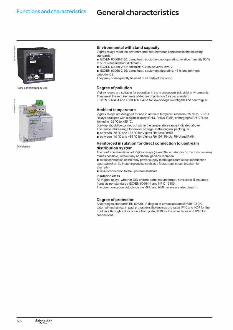
Front-panel mount device.
PB10
0435
-35_
SE.e
ps
DIN device.
General characteristics
A-9
Vigirex relays comply with environmental-protection regulations.
Vibration withstand capacityVigirex relays meet the requirements of Veritas and Lloyd’s (vibration test from 2 to 13.2 Hz ±1 mm and from 13.2 to 100 Hz – 0.7 g).
Labels and markings b UL, CE and as per IEC 60947-2 annex M, EAC marking b Vigirex relay supply voltage b Product part number b The origin (Schneider Electric) and the connection terminals (see pages A-16 to
A-22) are indicated on the product.
RecyclingThe packaging is made of recyclable cardboard.Vigirex relays comply with environmental-protection regulations:
b moulded parts are made of thermoplastic materials: v 10 % fibreglass reinforced polycarbonate (PC10FV) for DIN cases and front-panel
mount cases b the composition is indicated on the parts b when disposed of, these materials do not produce polluting substances, even
when burned.
DB
1259
81.e
psD
B12
5982
.eps
Information on the case.
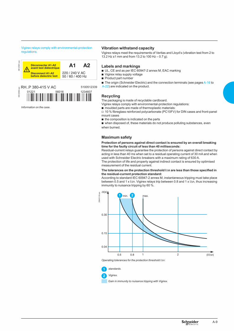
Maximum safetyProtection of persons against direct contact is ensured by an overall breaking time for the faulty circuit of less than 40 milliseconds:Residual-current relays guarantee the protection of persons against direct contact by acting in less than 40 ms when set to a residual operating current of 30 mA and when used with Schneider Electric breakers with a maximum rating of 630 A.The protection of life and property against indirect contact is ensured by optimised measurement of the residual current.The tolerances on the protection threshold IDn are less than those specified in the residual-current protection standard:According to standard IEC 60947-2 annex M, instantaneous tripping must take place between 0.5 and 1 x IDn. Vigirex relays trip between 0.8 and 1 x IDn, thus increasing immunity to nuisance tripping by 60 %.
DB
4031
39.e
ps
Operating tolerances for the protection threshold IDn:
standards.
Vigirex.
Gain in immunity to nuisance tripping with Vigirex.
A-10
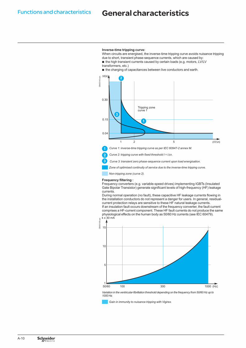
Inverse-time tripping curve:When circuits are energised, the inverse-time tripping curve avoids nuisance tripping due to short, transient phase-sequence currents, which are caused by:
b the high transient currents caused by certain loads (e.g. motors, LV/LV transformers, etc.)
b the charging of capacitances between live conductors and earth.
DB
4031
40.e
ps
Curve 1: inverse-time tripping curve as per IEC �0947-2 annex M.
Curve 2: tripping curve with fixed threshold I = IDn.
Curve �: transient zero phase-sequence current upon load energisation.
Zone of optimised continuity of service due to the inverse-time tripping curve.
Non-tripping zone (curve 2).
Frequency filtering :Frequency converters (e.g. variable-speed drives) implementing IGBTs (Insulated Gate Bipolar Transistor) generate significant levels of high-frequency (HF) leakage currents.During normal operation (no fault), these capacitive HF leakage currents flowing in the installation conductors do not represent a danger for users. In general, residual-current protection relays are sensitive to these HF natural leakage currents.If an insulation fault occurs downstream of the frequency converter, the fault current comprises a HF-current component. These HF fault currents do not produce the same physiological effects on the human body as 50/60 Hz currents (see IEC 60479).
DB
4031
38.e
ps
Variation in the ventricular-fibrillation threshold depending on the frequency from 50/60 Hz up to 1000 Hz.
Gain in immunity to nuisance tripping with Vigirex.
Functions and characteristics General characteristics
A-11
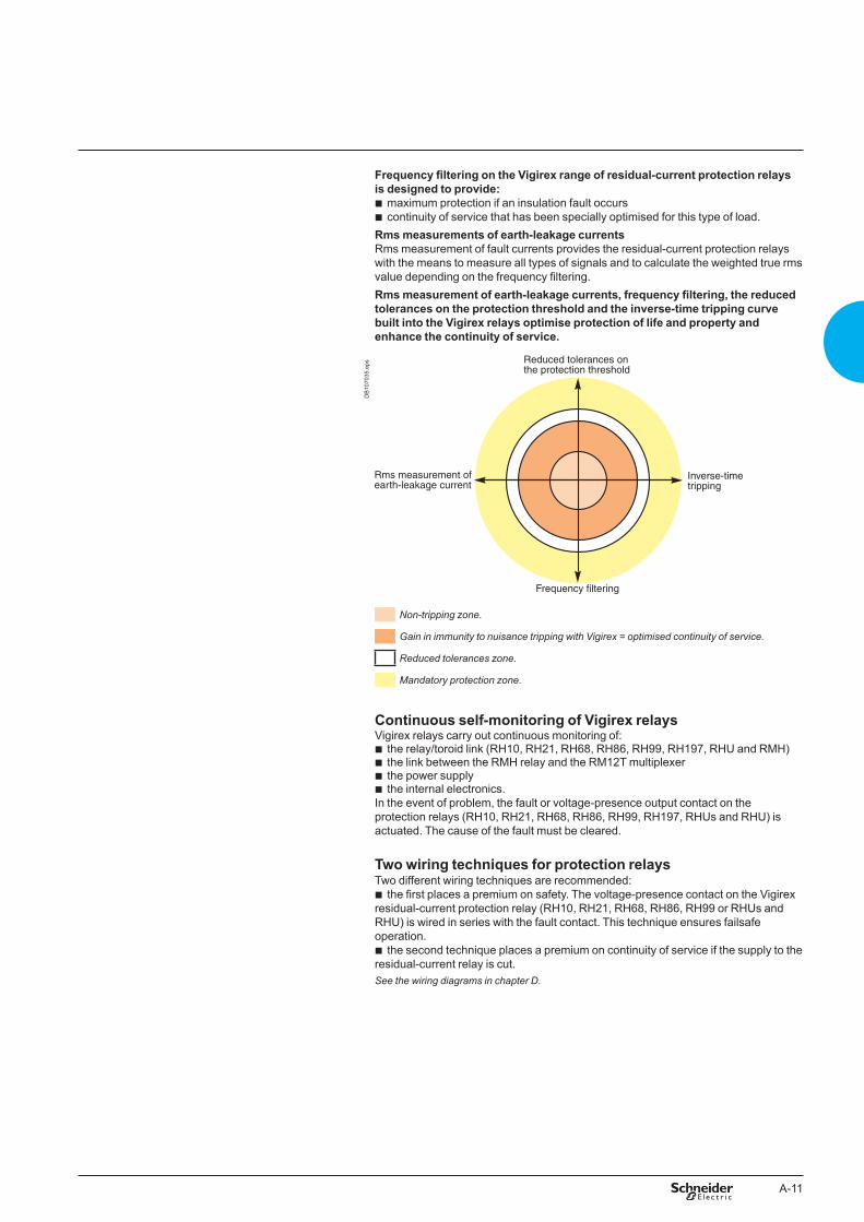
Frequency filtering on the Vigirex range of residual-current protection relays is designed to provide:
b maximum protection if an insulation fault occurs b continuity of service that has been specially optimised for this type of load.
Rms measurements of earth-leakage currentsRms measurement of fault currents provides the residual-current protection relays with the means to measure all types of signals and to calculate the weighted true rms value depending on the frequency filtering.Rms measurement of earth-leakage currents, frequency filtering, the reduced tolerances on the protection threshold and the inverse-time tripping curve built into the Vigirex relays optimise protection of life and property and enhance the continuity of service.
DB
1070
35.e
ps
Non-tripping zone.
Gain in immunity to nuisance tripping with Vigirex = optimised continuity of service.
Reduced tolerances zone.
Mandatory protection zone.
Continuous self-monitoring of Vigirex relaysVigirex relays carry out continuous monitoring of:
b the relay/toroid link (RH10, RH21, RH68, RH86, RH99, RH197, RHU and RMH) b the link between the RMH relay and the RM12T multiplexer b the power supply b the internal electronics.
In the event of problem, the fault or voltage-presence output contact on the protection relays (RH10, RH21, RH68, RH86, RH99, RH197, RHUs and RHU) is actuated. The cause of the fault must be cleared.
Two wiring techniques for protection relaysTwo different wiring techniques are recommended:
b the first places a premium on safety. The voltage-presence contact on the Vigirex residual-current protection relay (RH10, RH21, RH68, RH86, RH99 or RHUs and RHU) is wired in series with the fault contact. This technique ensures failsafe operation.
b the second technique places a premium on continuity of service if the supply to the residual-current relay is cut.See the wiring diagrams in chapter D.
A-12
Functions and characteristics
Test and resetTestAccording to standards IEC 60364 and NF C 15100, a periodic test is required to check correct operation of the residual-current protection system.The purpose of the test is to check:
b the output contacts: v the complete protection system with actuation of the output contacts (this shuts
down the installation) v the protection system without actuation of the output contacts (“no trip” test) to
maintain the installation up and running. b correct operation of the display (RHUs, RHU, RMH and the RH197 bargraph), the
LEDs and the internal electronics.ResetWhatever the test mode, a reset clears the fault stored in memory and resets the LEDs and the relay status condition.Test and reset modesFour possible modes Actuation of output contacts
No (1) YesLocal via button in front b b Remote 1 relay b (1) b (1)
a number of relays b (2) b (2)
Via communication b (RHU/RMH) b (RHU/RMH)(1) Except for RMH.(2) Except for the RMH/RH197M.
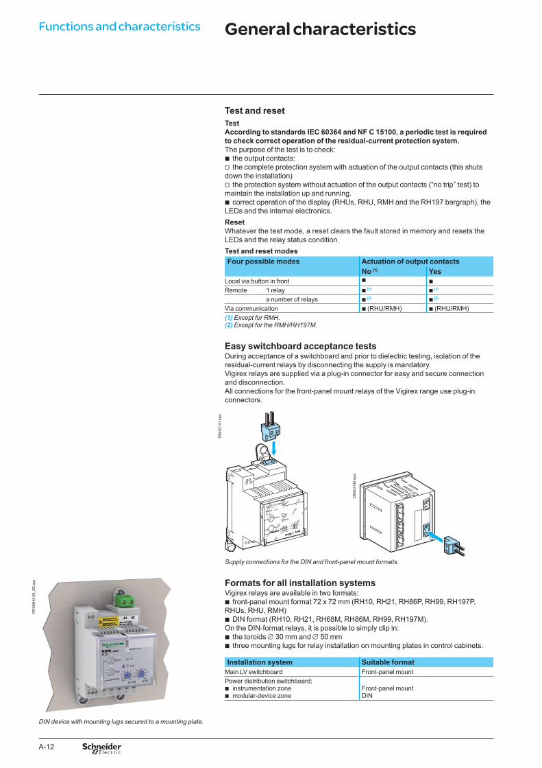
Easy switchboard acceptance testsDuring acceptance of a switchboard and prior to dielectric testing, isolation of the residual-current relays by disconnecting the supply is mandatory. Vigirex relays are supplied via a plug-in connector for easy and secure connection and disconnection.All connections for the front-panel mount relays of the Vigirex range use plug-in connectors.
t (S)
I n (A)
0.51 3
5
10
30
0.3
0.1
0.03
Test
0.250.31 0.5
0.8
1
4.50
0.15
0.06
Reseton
fault
Test no trip
Vigirex RH99M
t (S)
I n (A)
0.3
Test no trip t (S)
I n (A)
0.3
Test no trip
DB
4031
41.e
ps
DB
4031
42.e
ps
Supply connections for the DIN and front-panel mount formats.
PB10
0445
-60_
SE.e
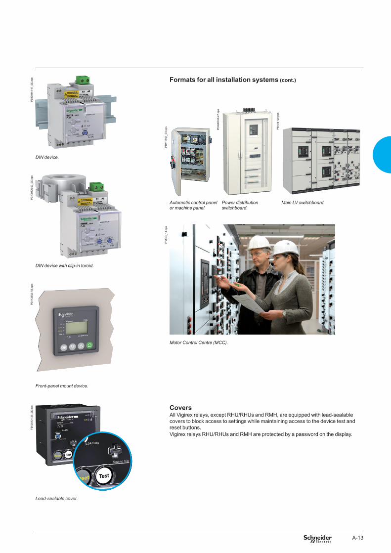
ps Formats for all installation systemsVigirex relays are available in two formats:
b front-panel mount format 72 x 72 mm (RH10, RH21, RH86P, RH99, RH197P, RHUs, RHU, RMH)
b DIN format (RH10, RH21, RH68M, RH86M, RH99, RH197M).On the DIN-format relays, it is possible to simply clip in:
b the toroids ∅ 30 mm and ∅ 50 mm b three mounting lugs for relay installation on mounting plates in control cabinets.
Installation system Suitable formatMain LV switchboard Front-panel mountPower distribution switchboard:
b instrumentation zone b modular-device zone
Front-panel mountDIN
DIN device with mounting lugs secured to a mounting plate.
General characteristics
A-13
PB10
0444
-47_
SE.e
ps Formats for all installation systems (cont.)
PB
1115
56_2
3.ep
s
PD
3903
38-2
7.ep
s
PB
1051
09.e
ps
DIN device.
PB10
0436
-53_
SE.e
ps
Automatic control panel or machine panel.
Power distribution switchboard.
Main LV switchboard.
iPM
CC
_14.
eps
DIN device with clip-in toroid.
PB
1138
82-R
5.ep
s
Motor Control Centre (MCC).
Front-panel mount device.
PB10
0431
-36_
SE.e
ps CoversAll Vigirex relays, except RHU/RHUs and RMH, are equipped with lead-sealable covers to block access to settings while maintaining access to the device test and reset buttons.Vigirex relays RHU/RHUs and RMH are protected by a password on the display.
Lead-sealable cover.
A-14
Functions and characteristicsD
B40
3143
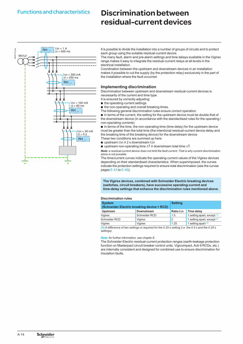
.eps It is possible to divide the installation into a number of groups of circuits and to protect
each group using the suitable residual-current device.The many fault, alarm and pre-alarm settings and time delays available in the Vigirex range makes it easy to integrate the residual-current relays at all levels in the electrical installation.Coordination between the upstream and downstream devices in an installation makes it possible to cut the supply (by the protection relay) exclusively in the part of the installation where the fault occurred.
Implementing discriminationDiscrimination between upstream and downstream residual-current devices is necessarily of the current and time type.It is ensured by correctly adjusting:
b the operating-current settings b the non-operating and overall breaking times.
The following general discrimination rules ensure correct operation: b in terms of the current, the setting for the upstream device must be double that of
the downstream device (in accordance with the standardised rules for the operating / non-operating currents)
b in terms of the time, the non-operating time (time delay) for the upstream device must be greater than the total time (the intentional residual-current device delay and the breaking time of the breaking device) for the downstream deviceThese two conditions are summed up here:
b upstream IDn u 2 x downstream IDn b upstream non-operating time DT u downstream total time DT.
Note: a residual-current device does not limit the fault current. That is why current discrimination alone is not possible.The time/current curves indicate the operating-current values of the Vigirex devices depending on their standardised characteristics. When superimposed, the curves indicate the protection settings required to ensure total discrimination (see the curves pages E-43 to E-46).
The Vigirex devices, combined with Schneider Electric breaking devices (switches, circuit breakers), have successive operating-current and time-delay settings that enhance the discrimination rules mentioned above.
Discrimination rulesSystem (Schneider Electric breaking device + RCD)
Setting
Upstream Downstream Ratio IDn Time delayVigirex Schneider RCD 1.5 1 setting apart, except (1)
Schneider RCD Vigirex 2 1 setting apart, except (1)
Vigirex Vigirex 1.25 1 setting apart (1)
(1) A difference of two settings is required for the 0.25 s setting (i.e. the 0.5 s and the 0.25 s settings).
Note: for further information, see chapter E.The Schneider Electric residual-current protection ranges (earth-leakage protection function on Masterpact circuit breaker control units, Vigicompact, Acti 9 RCDs, etc.) are internally consistent and designed for combined use to ensure discrimination for insulation faults.
Discrimination between residual-current devices

A-15
Electromagnetic disturbancesVigirex relays are immune to:
b overvoltages produced by switching (e.g. lighting circuits) b overvoltages produced by atmospheric disturbances b radio-frequency waves emitted by devices such as mobile telephones, radio
transmitters, walky-talkies, radar, etc. b electrostatic discharges produced directly by users.
To guarantee immunity, Vigirex relays are tested in compliance with the following standards:
b IEC/EN 60947-2: low-voltage switchgear and controlgear, part 2 circuit breakers) b IEC/EN 61000-4-1: overview of the IEC/EN 61000-4 series b IEC/EN 61000-4-2: electrostatic-discharge immunity test b IEC/EN 61000-4-3: radiated, radio-frequency, electromagnetic-field immunity test b IEC/EN 61000-4-4: electrical fast transient/burst immunity test b IEC/EN 61000-4-5: surge immunity test b IEC/EN 61000-4-6: immunity to conducted disturbances, induced by radio-
frequency fields b CISPR 11: limits and methods of measurement of electromagnetic disturbance
characteristics of industrial, scientific and medical (ISM) radiofrequency equipment.The high immunity levels of Vigirex relays ensure optimum safety without nuisance tripping.Behaviour during micro-outages in the auxiliary supplyVigirex relays are not affected by micro-outages lasting less than 60 ms.The maximum break time during micro-outages complies with standard IEC/EN 60947-2 annex M.
Electromagnetic compatibility
A-16
Functions and characteristicsPB
1004
37-3
2_SE
_r.e
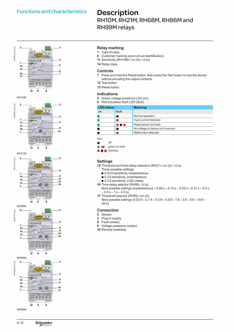
ps Relay marking1 Type of relay.4 Customer marking zone (circuit identification).11 Sensitivity (RH10M): IDn (A) / Dt (s).14 Relay class.
Controls7 Press and hold the Reset button, then press the Test button to test the device
without actuating the output contacts.12 Test button.13 Reset button.
Indications5 Green voltage-presence LED (on).6 Red insulation-fault LED (fault).
RH10M
PB10
0440
-32_
SE_r
.eps
LED status Meaningon fault
Normal operationFault current detected
Relay/sensor link faultNo voltage or device not in serviceMalfunction detected
Key:off
( ) green (or red) flashing.
RH21M.
PB
1081
73-4
8.ep
s
Settings15 Threshold and time-delay selectors (RH21): IDn (A) / Dt (s)
Three possible settings: b 0.03 A sensitivity, instantaneous b 0.3 A sensitivity, instantaneous b 0.3 A sensitivity, 0.06 s delay
16 Time-delay selector (RH99): Dt (s) Nine possible settings (instantaneous – 0.06 s – 0.15 s – 0.25 s – 0.31 s – 0.5 s – 0.8 s – 1 s – 4.5 s).
17 Threshold selector (RH99): IDn (A) Nine possible settings (0.03 A – 0.1 A – 0.3 A – 0.5 A – 1 A – 3 A – 5 A – 10 A – 30 A).
Connection2 Sensor.3 Plug-in supply.8 Fault contact.9 Voltage-presence contact.10 Remote reset/test.
RH�8M.
PB
1081
74-4
8.ep
s
RH8�M.
PB10
0439
-32_
SE_r
.eps
RH99M.
DescriptionRH10M, RH21M, RH68M, RH86M and RH99M relays
A-17
PB
1049
14-5
0t.e
ps Relay marking1 Type of relay.2 Customer marking zone (circuit identification).3 Relay class.
Controls9 Press and hold the Reset button, then press the Test button to test the device
without actuating the output contacts.10 Test button.11 Reset button.
Indications12 Green voltage-presence LED (on).13 Yellow alarm LEDs IDN: 20, 30, 40 and 50 %.14 Red insulation-fault LED (fault).
LED status Meaningon fault
Normal operationFault current detected
Faulty sensor/relay link No power or device not working
Key:off
green flashing.
4
12 0.1
I n
0.05
0.03
0.0750.2
0.3
0.15
(A)0.31
t
0.06
0
0.151
4.5
0.5
(s)
RH197M Vigirex
IEC 60947-2 / M50403020
%
x10x1
NeAuto
Al50% Al100%
NdManu
x100
k x I nFault
FaultAlarm
Reset Test T1
28
42 41 44 32 31 34
A2
220/240 VAC50/60/400 Hz
A1 27 26 25
T2
ON
Reset Test
Test no trip
2
7 8
13
14
15
16
6 5
1011
9
3
1DB
4032
04.e
ps
Settings15 Dip switch:
b Ne/Nd switch used to select the operating mode: v failsafe mode: position Ne v non-failsafe mode: position Nd b “Auto/Manual” switch used to select fault relay reset mode v in “Manual” position: latching relay requiring the Reset button to be pressed
after fault clearing v in “Auto” position: automatic reset of fault relay (after fault clearing) v 10 resets are possible according to the following algorithm: - 1st reset: 30 s after the fault - 2nd reset: 1 min. after the fault - 3rd reset: 2 min. after the fault - 4th reset: 4 min. after the fault - 5th reset: 8 min. after the fault - 6th reset: 16 min. after the fault - 7th reset: 32 min. after the fault - 8th reset: 64 min. after the fault - 9th reset: 128 min. after the fault - 10th reset: 256 min. after the fault
The trip counter is reset 30 minutes after fault relay reset. b Al 50 % - 100 % (setting by Dip switch at 50 % of IDn or 100 % of IDn). b Selector gain for IDn.
16 Threshold IDn (A): 19 possible settings (0.03 A – 0.05 A – 0.075 A – 0.1 A – 0.15 A – 0.2 A – 0.3 A – 0.5 A – 0.75 A –1 A – 1.5 A – 2 A – 3 A – 5 A – 7.5 A – 10 A – 15 A – 20 A – 30 A). Time-delay selector Dt (s): 7 possible settings (instantaneous – 0.06 s – 0.15 s – 0.31 s – 0.5 s – 1 s – 4.5 s).
Connection4 Plug-in supply.5 Fault contact.6 Alarm contact7 Remote reset/test.8 Sensor.
RH197M.
RH197M relays

A-18
PB10
0441
-40_
SE.e
ps Relay marking1 Type of relay.4 Customer marking zone (circuit identification).8 Sensitivity (RH10P): IDn (A) / Dt (s).9 Relay class.
Controls5 Test button.6 Reset button.7 Press and hold the Reset button, then press the Test button to test the device
without actuating the output contacts.
Indications2 Green voltage-presence LED (on).3 Red insulation-fault LED (fault).
RH10P.
PB10
0442
-40_
SE.e
ps
LED status Meaningon fault
Normal operationFault current detected
Relay/sensor link faultNo voltage or device not in serviceMalfunction detected
Key:RH21P. off
PB
1081
72.e
ps ( ) green (or red) flashing.
Settings10 Threshold and time-delay selectors (RH21): IDn (A) / Dt (s)
Three possible settings: b 0.03 A sensitivity, instantaneous b 0.3 A sensitivity, instantaneous b 0.3 A sensitivity, 0.06 s delay
11 Time-delay selector (RH99): Dt (s) Nine possible settings (instantaneous – 0.06 s – 0.15 s – 0.25 s – 0.31 s – 0.5 s – 0.8 s – 1 s – 4.5 s).
12 Threshold selector (RH99): IDn (A) Nine possible settings (0.03 A – 0.1 A – 0.3 A – 0.5 A – 1 A – 3 A – 5 A – 10 A – 30 A).
ConnectionAll connections for front-panel mount relays are of the plug-in type.13 Fault contact.14 Sensor.15 Plug-in supply.16 Voltage-presence contact.17 Remote reset/test.
RH8�P.
PB10
0438
-40_
SE.e
ps
RH99P.
PB
1047
84.e
ps
Connections on the back of the relay.
Functions and characteristics DescriptionRH10P, RH21P, RH86P and RH99P relays
A-19
PB10
0716
-40_
SE.e
ps
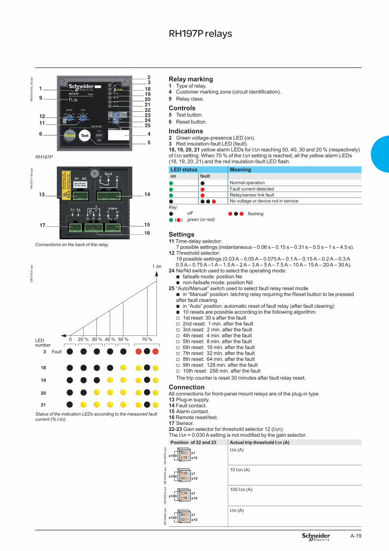
RH197P
Relay marking1 Type of relay.4 Customer marking zone (circuit identification).9 Relay class.
Controls5 Test button.6 Reset button.
Indications2 Green voltage-presence LED (on).3 Red insulation-fault LED (fault).18, 19, 20, 21 yellow alarm LEDs for IDn reaching 50, 40, 30 and 20 % (respectively) of IDn setting. When 70 % of the IDn setting is reached, all the yellow alarm LEDs (18, 19, 20, 21) and the red insulation-fault LED flash.
Connections on the back of the relay.
PB
1007
17-4
0.ep
s LED status Meaningon fault
Normal operationFault current detected
Relay/sensor link fault No voltage or device not in service
Key:off flashing
( ) green (or red)
Settings11 Time-delay selector:
7 possible settings (instantaneous – 0.06 s – 0.15 s – 0.31 s – 0.5 s – 1 s – 4.5 s).12 Threshold selector:
19 possible settings (0.03 A – 0.05 A – 0.075 A – 0.1 A – 0.15 A – 0.2 A – 0.3 A 0.5 A – 0.75 A –1 A – 1.5 A – 2 A – 3 A – 5 A – 7.5 A – 10 A – 15 A – 20 A – 30 A).
24 Ne/Nd switch used to select the operating mode: b failsafe mode: position Ne b non-failsafe mode: position Nd
25 “Auto/Manual” switch used to select fault relay reset mode b in “Manual” position: latching relay requiring the Reset button to be pressed
after fault clearing b in “Auto” position: automatic reset of fault relay (after fault clearing) b 10 resets are possible according to the following algorithm: v 1st reset: 30 s after the fault v 2nd reset: 1 min. after the fault v 3rd reset: 2 min. after the fault v 4th reset: 4 min. after the fault v 5th reset: 8 min. after the fault v 6th reset: 16 min. after the fault v 7th reset: 32 min. after the fault v 8th reset: 64 min. after the fault v 9th reset: 128 min. after the fault v 10th reset: 256 min. after the fault
The trip counter is reset 30 minutes after fault relay reset.
ConnectionAll connections for front-panel mount relays are of the plug-in type.13 Plug-in supply.14 Fault contact.15 Alarm contact.16 Remote reset/test.17 Sensor.22-23 Gain selector for threshold selector 12 (IDn):The IDn = 0.030 A setting is not modified by the gain selector.
I ∆n
70 %50 %40 %30 %20 %0
Fault3
18
19
20
21
LED number
DB
1070
37.e
ps
Status of the indication LEDs according to the measured fault current (% IDn).
Position of 22 and 23 Actual trip threshold IDn (A)
DB
1069
33.e
ps IDn (A)
DB
1069
34.e
ps 10 IDn (A)
DB
1069
35.e
ps 100 IDn (A)
DB
1069
82.e
ps IDn (A)
RH197P relays
A-20
Functions and characteristics
OK
Vigirex RHU
IEC 60947-2 / M
1
2
3
DB
4190
62.e
ps
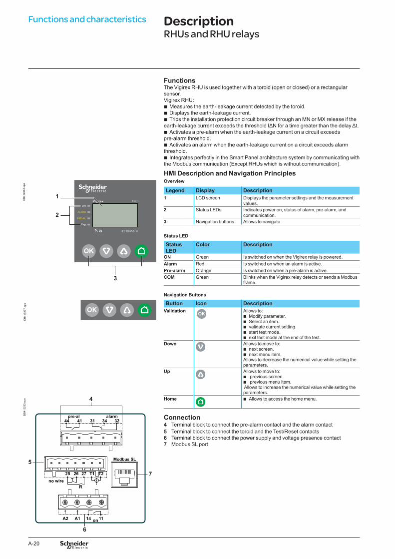
FunctionsThe Vigirex RHU is used together with a toroid (open or closed) or a rectangular sensor.Vigirex RHU:
b Measures the earth-leakage current detected by the toroid. b Displays the earth-leakage current. b Trips the installation protection circuit breaker through an MN or MX release if the
earth-leakage current exceeds the threshold IΔN for a time greater than the delay Δt. b Activates a pre-alarm when the earth-leakage current on a circuit exceeds
pre-alarm threshold. b Activates an alarm when the earth-leakage current on a circuit exceeds alarm
threshold. b Integrates perfectly in the Smart Panel architecture system by communicating with
the Modbus communication (Except RHUs which is without communication).
HMI Description and Navigation Principles Overview
Legend Display Description1 LCD screen Displays the parameter settings and the measurement
values.2 Status LEDs Indicates power on, status of alarm, pre-alarm, and
communication.3 Navigation buttons Allows to navigate
Status LED
Status LED
Color Description
ON Green Is switched on when the Vigirex relay is powered.Alarm Red Is switched on when an alarm is active.Pre-alarm Orange Is switched on when a pre-alarm is active.COM Green Blinks when the Vigirex relay detects or sends a Modbus
frame.
Navigation Buttons
OK
DB
4192
77.e
ps Button Icon DescriptionValidation
OK
Allows to: b Modify parameter. b Select an item. b validate current setting. b start test mode. b exit test mode at the end of the test.
Down Allows to move to: b next screen. b next menu item.
Allows to decrease the numerical value while setting theparameters.
Up Allows to move to: b previous screen. b previous menu item.
Allows to increase the numerical value while setting the parameters.
Home b Allows to access the home menu.
5
7
6
4
Modbus SL
32alarmpre-al
34314144
1114 onA1A2
T1 T227Tno wire
R
2625
DB
4192
83.e
ps
Connection4 Terminal block to connect the pre-alarm contact and the alarm contact5 Terminal block to connect the toroid and the Test/Reset contacts6 Terminal block to connect the power supply and voltage presence contact7 Modbus SL port
DescriptionRHUs and RHU relays

A-21
FunctionsThe Vigirex RMH is used together with a Vigirex RM12T and toroid (open or closed) or a rectangular sensor.Vigirex RMH:
b Measures the earth-leakage current detected by the toroids (12 maximum). b Displays the earth-leakage current. b Activates a pre-alarm when the earth-leakage current on a circuit exceeds its
pre-alarm threshold. b Activates an alarm when the earth-leakage current on a circuit exceeds its alarm
threshold. b Integrates perfectly in the Smart Panel architecture system by communicating with
the Modbus communication.
Alarm DetectionAn alarm is active when the measured earth-leakage current is greater than the set alarm threshold (I alarm) on at least one toroid for a period of time greater than the set alarm delay (t alarm in milliseconds or seconds) for that particular toroid.When an alarm is active:
b the ALARM and PRE-AL LED are switched on. b When only one alarm is detected, the Metering screen of the corresponding toroid
is displayed, and the earth-leakage current value blinks. b When more than one alarm are detected, the Alarm screen is displayed.
Pre-Alarm DetectionA pre-alarm is active when the measured earth-leakage current is greater than the set pre-alarm threshold on at least one channel for a period of time greater than the set pre-alarm trip delay (t pre-alarm in milliseconds or seconds) for that particular toroid.When a pre-alarm is active:
b the PRE-AL LED is switched on and the displayed value blinks. b When only one pre-alarm is detected, the Metering screen of the corresponding
toroid is displayed, and the earth-leakage current value blinks. b When more than one alarm are detected, the Pre-alarm screen is displayed.
HMI Description and Navigation Principles
OK
Vigirex RMH1
2
3
DB
4190
63.e
ps
Overview
Legend Display Description1 LCD screen Displays the parameter settings and the measurement
values.2 Status LEDs Indicates power on, status of alarm, pre-alarm, and
communication3 Navigation buttons Allows to navigate
Status LED
Status LED
Color Description
ON Green Is switched on when the Vigirex relay is powered.Alarm Red Is switched on when an alarm is active.Pre-alarm Orange Is switched on when a pre-alarm is active.COM Green Blinks when the Vigirex relay detects or sends a Modbus
frame.
Navigation Buttons
OK
DB
4192
77.e
ps Button Icon DescriptionValidation
OK
Allows to: b select an item. b modify parameter. b validate current setting. b start test mode. b exit test mode at the end of the test.
Down Allows to move to: b next screen. b next menu item.
Allows you to decrease the numerical value.Up Allows to move to:
b previous screen. b previous menu item.
Allows to increase the numerical value.Home Allows to access the home menu.
RMH relay and RM12T multiplexer
A-22
Functions and characteristics
Modbus SL
no wire23 24 21 22
RM12T23 24 21 22
32alarmpre-al
34314144
1114 onA1A2
5
7
6
4
DB
4192
82.e
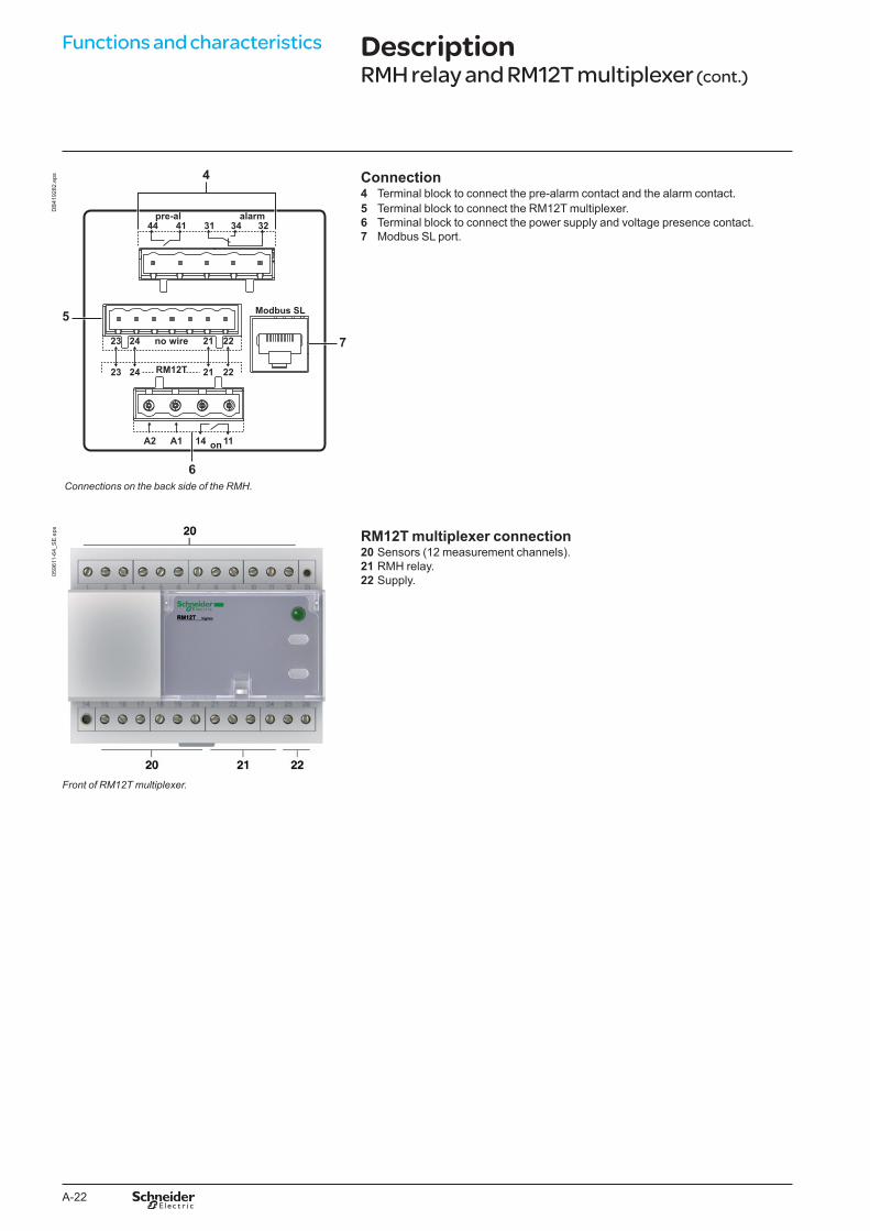
ps Connection4 Terminal block to connect the pre-alarm contact and the alarm contact.5 Terminal block to connect the RM12T multiplexer.6 Terminal block to connect the power supply and voltage presence contact.7 Modbus SL port.
Connections on the back side of the RMH.
0596
11-6
4_S
E.e
ps RM12T multiplexer connection20 Sensors (12 measurement channels).21 RMH relay.22 Supply.
Front of RM12T multiplexer.
DescriptionRMH relay and RM12T multiplexer (cont.)
A-23
RHU and RMH are equipped for Modbus communication serial in line.
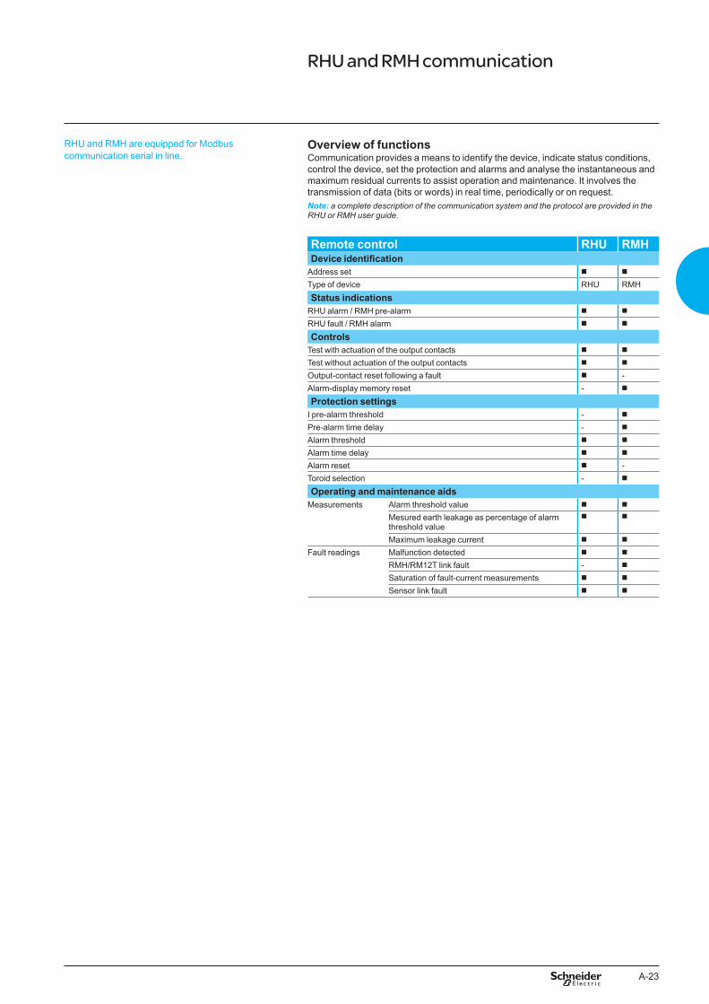
Overview of functionsCommunication provides a means to identify the device, indicate status conditions, control the device, set the protection and alarms and analyse the instantaneous and maximum residual currents to assist operation and maintenance. It involves the transmission of data (bits or words) in real time, periodically or on request.Note: a complete description of the communication system and the protocol are provided in the RHU or RMH user guide.
Remote control RHU RMHDevice identification
Address set b b
Type of device RHU RMHStatus indications
RHU alarm / RMH pre-alarm b b
RHU fault / RMH alarm b b
ControlsTest with actuation of the output contacts b b
Test without actuation of the output contacts b b
Output-contact reset following a fault b -Alarm-display memory reset - b
Protection settingsI pre-alarm threshold - b
Pre-alarm time delay - b
Alarm threshold b b
Alarm time delay b b
Alarm reset b -Toroid selection - b
Operating and maintenance aidsMeasurements Alarm threshold value b b
Mesured earth leakage as percentage of alarm threshold value
b b
Maximum leakage current b b
Fault readings Malfunction detected b b
RMH/RM12T link fault - b
Saturation of fault-current measurements b b
Sensor link fault b b
RHU and RMH communication
A-24
Functions and characteristics
Vigirex RHU in Communication Architecture
ETH1
ETH2
ETH1ETH2
24VDC
24 Vdc
L
F
C
B
I
13
O1
+
I1
24VDC
I2I3
I4I5
I6
C
C
C
1423
2433
34T1
T2
O2
O3
A1
Modbus-SL
OK
Vigirex
RHU
IEC 60947-2 / M
J K
H
F
EthernetModbus-SL
EG
D A
DB
4198
81.e
ps
Vigirex RMH in Communication Architecture
1 2 3 4 5 6 7 8 9 10 11 12 13
RM12T
OK
Vigirex
RMH
ETH1
ETH2
ETH1ETH2
24VDC
24 Vdc
L
F
C
B
I
13
O1
+
I1
24VDC
I2I3
I4I5
I6
C
C
C
1423
2433
34T1
T2
O2
O3
A1
Modbus-SL
J K
H
F
E
G G G
M
EthernetModbus-SL
D
Sensor 1 Sensor 2 Sensor 12
A
DB
4198
82.e
ps
DescriptionRHU and RMH communication
A FDM128 ethernet display (LV4�4128)B IFE gateway (LV�4011)C IFM (TRV00210)D Vigirex relay RHUR FDM 121 (TRV00121)F ULP cableG Vigirex sensorH IO Module (LV4�40��)I Masterpact NT/NWJ Breaker ULP cordK NSX cordL Compact NSX/Powerpact H-, J-, L- frame
A FDM128 ethernet display (LV4�4128)B IFE gateway (LV�4011)C IFM (TRV00210)D Vigirex relay RMHE FDM 121 (TRV00121)F ULP cableG Vigirex sensor (up to 12 sensors)H IO Module (LV4�40��)I Masterpact NT/NWJ Breaker ULP cordK NSX cordL Compact NSX/Powerpact H-, J-, L- frameM Vigirex RM12T multiplexer
A-25
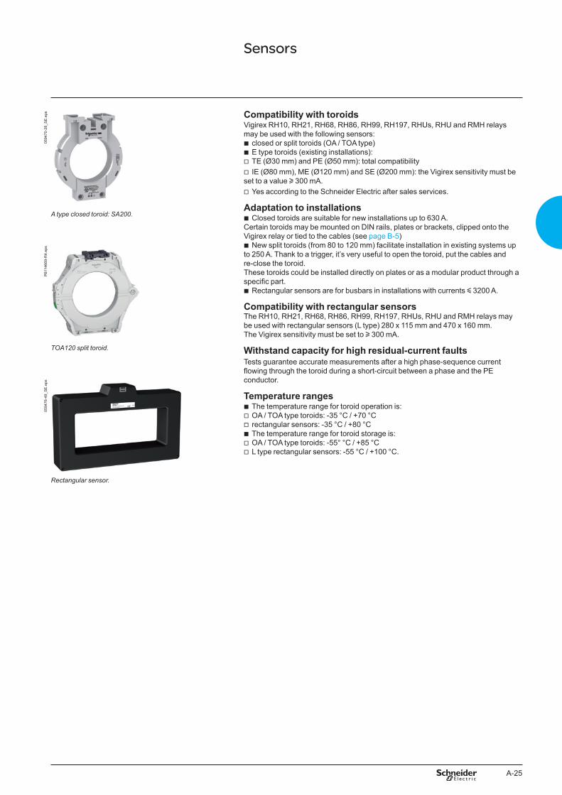
0594
70-2
8_S
E.e
ps Compatibility with toroidsVigirex RH10, RH21, RH68, RH86, RH99, RH197, RHUs, RHU and RMH relays may be used with the following sensors:
b closed or split toroids (OA / TOA type) b E type toroids (existing installations): v TE (Ø30 mm) and PE (Ø50 mm): total compatibility v IE (Ø80 mm), ME (Ø120 mm) and SE (Ø200 mm): the Vigirex sensitivity must be
set to a value u 300 mA. v Yes according to the Schneider Electric after sales services.
Adaptation to installations b Closed toroids are suitable for new installations up to 630 A.
Certain toroids may be mounted on DIN rails, plates or brackets, clipped onto the Vigirex relay or tied to the cables (see page B-5)
b New split toroids (from 80 to 120 mm) facilitate installation in existing systems up to 250 A. Thank to a trigger, it’s very useful to open the toroid, put the cables and re-close the toroid. These toroids could be installed directly on plates or as a modular product through a specific part.
b Rectangular sensors are for busbars in installations with currents y 3200 A.
Compatibility with rectangular sensorsThe RH10, RH21, RH68, RH86, RH99, RH197, RHUs, RHU and RMH relays may be used with rectangular sensors (L type) 280 x 115 mm and 470 x 160 mm. The Vigirex sensitivity must be set to u 300 mA.
Withstand capacity for high residual-current faultsTests guarantee accurate measurements after a high phase-sequence current flowing through the toroid during a short-circuit between a phase and the PE conductor.
Temperature ranges b The temperature range for toroid operation is: v OA / TOA type toroids: -35 °C / +70 °C v rectangular sensors: -35 °C / +80 °C b The temperature range for toroid storage is: v OA / TOA type toroids: -55° °C / +85 °C v L type rectangular sensors: -55 °C / +100 °C.
A type closed toroid: SA200.
PB
1146
69-R
4.ep
s
TOA120 split toroid.
0594
76-4
9_S
E.e
ps
Rectangular sensor.
Sensors

A-26
Functions and characteristics
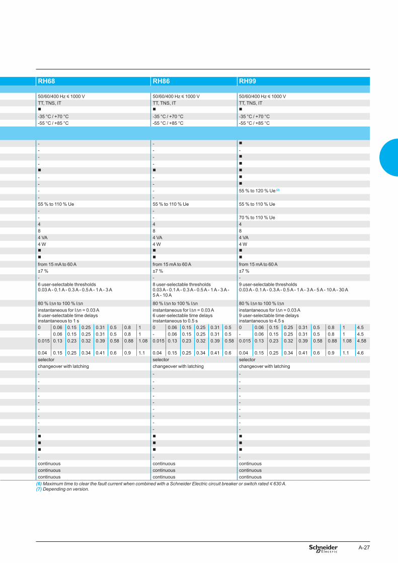
Vigirex relays RH10 RH21General characteristicsMonitored distribution system: LV AC / System voltage 50/60/400 Hz y 1000 V 50/60/400 Hz y 1000 VSystem earthing arrangement TT, TNS, IT TT, TNS, ITA, AC type class as per IEC 60947-2 appendix M (1) b b
Operating-temperature range -35 °C / +70 °C -35 °C / +70 °CStorage-temperature range -55 °C / +85 °C -55 °C / +85 °CElectrical characteristics as per IEC 60755 and EN 60755, IEC 60947-2 and EN 60947-2, UL 1053 and CSA C22.2 N° 144 for RH10 to 99 with Ue y 220 VPower supply: rated operational voltage Ue
12 to 24 V AC -12 to 48 V DC 50/60 Hz / DC b b
48 V AC - 24 to 130 V DC 50/60 Hz / DC - -48 V AC 50/60 Hz b b
110 to 130 V AC 50/60 Hz b b
220 to 240 V AC 50/60/400 Hz b b
380 to 415 V AC 50/60 Hz b b
440 to 525 V AC 50/60 Hz b b
Operational voltage tolerances
Ue : 12 to 24 V AC - 12 to 48 V DC 55 % to 120 % Ue (2) 55 % to 120 % Ue (2)
Ue : 48 V AC - 24 to 130 V DC - -Ue : 48 to 415 V 55 % to 110 % Ue 55 % to 110 % UeUe : 110 to 415 V - -Ue > 415 V 70 % to 110 % Ue 70 % to 110 % Ue
Overvoltage category 4 4Rated impulse withstand voltage up to Ue = 525 V AC Uimp (kV) 8 8Maximum consumption AC 4 VA 4 VA
DC 4 W 4 WInsensitive to micro-outages y 60 ms b b
Maximum break time on toroid failure (as per standard IEC 60947-2) b b
Leakage-current measurements Measurement range from 15 mA to 60 A from 15 mA to 60 AMeasurement accuracy ±7 % ±7 %Display refresh time - -
Fault current detection Threshold IDn 1 fixed threshold 0.03 A - 0.05 A - 0.1 A - 0.15 A 0.25 A - 0.3 A - 0.5 A - 1 A
2 user-selectable thresholds 0.03 A or 0.3 A
Fault-current detection range 80 % IDn to 100 % IDn 80 % IDn to 100 % IDnTime delay Dt instantaneous instantaneous for IDn = 0,03 A
1 user-selectable time delayinstantaneous or 0.06 s for IDn = 0.3 A
Dt settings (s) 0 0 0.06Maximum non-operating time at 2 IDn (s) - - 0.06Maximum operating time at 5 IDn (s) (residual-current relay alone)
0.015 0.015 0.13
Maximum total time at 5 IDn (6) (s) 0.04 0.04 0.15Setting none selectorOutput contact changeover with latching changeover with latching
Alarm I alarm threshold - -Alarm-current detection range - -Time delay Dt alarm - -Dt alarm settings - -Maximum non-detection time at 2 I alarm - -Maximum detection time at 5 I alarm - -Setting - -Output contact - -Hysteresis - -
Test with or without actuationof the output contacts andoutput-contact resetfollowing a fault
Local b b
Remote (hard-wired) (10 m maximum) b b
Remote (hard-wired for several relays) (10 m maximum) b b
Remote (via communication) - -Self-monitoring Relay/sensor link continuous continuous
Power supply continuous continuousElectronics continuous continuous
(1) Type A relays up to 5 A.(2) 80 % to 120 % Ue if Ue < 20 V.(3) 80 % to 110 % Ue if Ue < 28 V.
(4) 85 % during energisation.(5) < 10 % of IDn: display = 0 and > 200 % of IDn: display = SAT.
CharacteristicsProtection relays with output contact requiring local manual reset after a fault
A-27
RH68 RH86 RH99
50/60/400 Hz y 1000 V 50/60/400 Hz y 1000 V 50/60/400 Hz y 1000 VTT, TNS, IT TT, TNS, IT TT, TNS, ITb b b
-35 °C / +70 °C -35 °C / +70 °C -35 °C / +70 °C-55 °C / +85 °C -55 °C / +85 °C -55 °C / +85 °C
- - b
- - -- - b
- - b
b b b
- - b
- - b
- - 55 % to 120 % Ue (2)
- -55 % to 110 % Ue 55 % to 110 % Ue 55 % to 110 % Ue- -- - 70 % to 110 % Ue4 4 48 8 84 VA 4 VA 4 VA4 W 4 W 4 Wb b b
b b b
from 15 mA to 60 A from 15 mA to 60 A from 15 mA to 60 A±7 % ±7 % ±7 %- - -6 user-selectable thresholds 0.03 A - 0.1 A - 0.3 A - 0.5 A - 1 A - 3 A
8 user-selectable thresholds 0.03 A - 0.1 A - 0.3 A - 0.5 A - 1 A - 3 A - 5 A - 10 A
9 user-selectable thresholds 0.03 A - 0.1 A - 0.3 A - 0.5 A - 1 A - 3 A - 5 A - 10 A - 30 A
80 % IDn to 100 % IDn 80 % IDn to 100 % IDn 80 % IDn to 100 % IDninstantaneous for IDn = 0.03 A8 user-selectable time delaysinstantaneous to 1 s
instantaneous for IDn = 0.03 A6 user-selectable time delaysinstantaneous to 0.5 s
instantaneous for IDn = 0.03 A9 user-selectable time delaysinstantaneous to 4.5 s
0 0.06 0.15 0.25 0.31 0.5 0.8 1 0 0.06 0.15 0.25 0.31 0.5 0 0.06 0.15 0.25 0.31 0.5 0.8 1 4.5- 0.06 0.15 0.25 0.31 0.5 0.8 1 - 0.06 0.15 0.25 0.31 0.5 - 0.06 0.15 0.25 0.31 0.5 0.8 1 4.50.015 0.13 0.23 0.32 0.39 0.58 0.88 1.08 0.015 0.13 0.23 0.32 0.39 0.58 0.015 0.13 0.23 0.32 0.39 0.58 0.88 1.08 4.58
0.04 0.15 0.25 0.34 0.41 0.6 0.9 1.1 0.04 0.15 0.25 0.34 0.41 0.6 0.04 0.15 0.25 0.34 0.41 0.6 0.9 1.1 4.6selector selector selectorchangeover with latching changeover with latching changeover with latching- - -- - -- - -- - -- - -- - -- - -- - -- - -b b b
b b b
b b b
- - -continuous continuous continuouscontinuous continuous continuouscontinuous continuous continuous
(6) Maximum time to clear the fault current when combined with a Schneider Electric circuit breaker or switch rated y ��0 A.(7) Depending on version.
A-28
Functions and characteristics
Vigirex relays RH197M RH197P RHUs and RHUGeneral characteristicsMonitored distribution system: LV AC / System voltage 50/60/400 Hz y 1000 V 50/60/400 Hz y 1000 V 50/60/400 Hz y 1000 VSystem earthing arrangement TT, TNS, IT TT, TNS, IT TT, TNS, ITA, AC type class as per IEC 60947-2 appendix M (1) b b b
Operating-temperature range -25 °C / +55 °C -25 °C / +55 °C -25 °C / +55 °CStorage-temperature range -40 °C / +85 °C -40 °C / +85 °C -40 °C / +85 °CElectrical characteristics as per IEC 60755 and EN 60755, IEC 60947-2 and EN 60947-2, UL 1053 and CSA C22.2 N° 144 for RH10 to 99 with Ue y 220 VPower supply: rated operational voltage Ue
12 to 24 V AC -12 to 48 V DC 50/60 Hz / DC - - -48 V AC - 24 to 130 V DC 50/60 Hz / DC b b -110 to 130 V AC 50/60 Hz b (3) b b
220 to 240 V AC 50/60/400 Hz b (3) b b
380 to 415 V AC 50/60 Hz b (3) b -440 to 525 V AC 50/60 Hz - - -
Operational voltage tolerances
Ue : 12 to 24 V AC - 12 to 48 V DC - - -Ue : 48 V AC - 24 to 130 V DC 80 % to 110 % Ue (4) 70 % to 110 % Ue -Ue : 48 to 415 V - - 70 % to 110 % Ue (5)
Ue : 110 to 415 V 85 % to 110 % Ue 70 % to 110 % Ue -Ue > 415 V - - -
Overvoltage category 4 4 4Rated impulse withstand voltage up to Ue = 525 V AC Uimp (kV) 8 8 8Maximum consumption AC 4 VA 4 VA 4 VA
DC 4 W 4 W -Insensitive to micro-outages y 60 ms b b b
Maximum break time on toroid failure (as per standard IEC 60947-2) b b b
Leakage-current measurements Measurement range - - from 15 mA to 60 AMeasurement accuracy ±7 % ±7 % ±7 %Display measurement 4 DEL 20, 30, 40 and 50 % of IDn 4 DEL 20, 30, 40 and 50 % of IDn from ±10 % (6) to 200 % of IDnDisplay refresh time 0.5 s 0.5 s 2 s
Fault current detection Threshold IDn 19 user-selectable thresholds0.03 A - 0.05 A - 0.075 A - 0.1 A - 0.15 A - 0.2 A 0.3 A - 0.5 A - 0.75 A - 1 A - 1.5 A - 2 A - 3 A - 5 A 7.5 A - 10 A - 15 A - 20 A - 30 A
19 user-selectable thresholds0.03 A - 0.05 A - 0.075 A - 0.1 A - 0.15 A - 0.2 A 0.3 A - 0.5 A - 0.75 A - 1 A - 1.5 A - 2 A - 3 A - 5 A 7.5 A - 10 A - 15 A - 20 A - 30 A
1 adjustable threshold from 0.03 A to 1 A in 0.001 A steps from 1 A to 30 A in 0.1 A steps
Fault-current detection range 80 % IDn to 100 % IDn 80 % IDn to 100 % IDn 80 % IDn to 100 % IDnTime delay Dt instantaneous for IDn = 0.03 A
7 user-selectable time delaysinstantaneous to 4.5 s
instantaneous for IDn = 0.03 A 7 user-selectable time delaysinstantaneous to 4.5 s
instantaneous for IDn = 0.03 A1 adjustable time delay to 4.5 s in 10 ms steps
Dt settings (s) 0 0.06 0.15 0.31 0.5 1 4.5 0 0.06 0.15 0.31 0.5 1 4.5 0 0.06 y DtMaximum non-operating time at 2 IDn (s) - 0.06 0.15 0.31 0.5 1 4.5 - 0.06 0.15 0.31 0.5 1 4.5 - same as for RH99Maximum operating time at 5 IDn (s) (residual-current relay alone)
0.020 0.13 0.32 0.39 0.58 1.08 4.58 0.020 0.13 0.32 0.39 0.58 1.08 4.58 0.015 same as for RH99
Maximum total time at 5 IDn (2) (s) 0.04 0.20 0.34 0.41 0.6 1.1 4.6 0.04 0.20 0.34 0.41 0.6 1.1 4.6 0.04 same as for RH99Setting selector selector keypadOutput contact changeover with latching in manual position; 10 automatic
resets in auto position (see algorithm)changeover with latching in manual position; 10 automatic resets in auto position (see algorithm)
changeover with latching
Alarm I alarm threshold setting by Dip switch at 50 % of IDn or 100 % of IDn fixed at 50 % of IDn or 100 % of IDn (7) 1 adj. threshold from 20 to 100 % IDn0.015 A to 1 A in 0.001 A steps1 A to 30 A in 0.1 A steps0.015 A < I alarm < 30 A
Alarm-current detection range ±7 % of IDn ±7 % of IDn 80 % I alarm to 100 % I alarmTime delay Dt alarm instantaneous instantaneous 1 adjustable time delay
instantaneous to 4.5 s in 10 ms stepsDt alarm settings - - 0 s 0.06 s y Dt Maximum non-detection time at 2 I alarm - - - same as for IDnMaximum detection time at 5 I alarm - - 0.015 s same as for IDnSetting - - keypadOutput contact NO without latching NO without latching YESHysteresis 0, -10 % IDn 0, -10 % IDn alarm deactivated at 70 % of I alarm
thresholdTest with or without actuationof the output contacts andoutput-contact resetfollowing a fault
Local b b b
Remote (hard-wired) (10 m maximum) b (8) b b
Remote (hard-wired for several relays) (10 m maximum) - b b
Remote (via communication) - - b RHU onlySelf-monitoring Relay/sensor link continuous continuous continuous
Power supply continuous continuous continuousElectronics watch-dog in microprocessor watch-dog in microprocessor continuous
CharacteristicsProtection relays with output contact requiring local manual reset after a fault
(1) Type A relays up to 5 A.(2) Maximum time to clear the fault current when combined with a Schneider Electric circuit breaker or switch rated y ��0 A.(3) 110 VAC, 2�0 VAC and 400 VAC only.(4) 80 % to 110 % Ue if Ue < 28 V.(5) 85 % during energisation.(6) < 10 % of IDn: display = 0 and > 200 % of IDn: display = SAT.(7) Depending on version.(8) Not available for DC version.
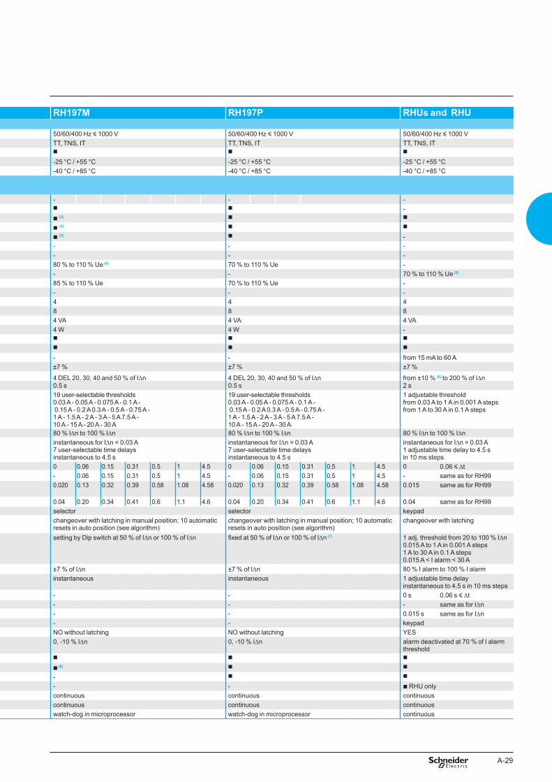
A-29
Vigirex relays RH197M RH197P RHUs and RHUGeneral characteristicsMonitored distribution system: LV AC / System voltage 50/60/400 Hz y 1000 V 50/60/400 Hz y 1000 V 50/60/400 Hz y 1000 VSystem earthing arrangement TT, TNS, IT TT, TNS, IT TT, TNS, ITA, AC type class as per IEC 60947-2 appendix M (1) b b b
Operating-temperature range -25 °C / +55 °C -25 °C / +55 °C -25 °C / +55 °CStorage-temperature range -40 °C / +85 °C -40 °C / +85 °C -40 °C / +85 °CElectrical characteristics as per IEC 60755 and EN 60755, IEC 60947-2 and EN 60947-2, UL 1053 and CSA C22.2 N° 144 for RH10 to 99 with Ue y 220 VPower supply: rated operational voltage Ue
12 to 24 V AC -12 to 48 V DC 50/60 Hz / DC - - -48 V AC - 24 to 130 V DC 50/60 Hz / DC b b -110 to 130 V AC 50/60 Hz b (3) b b
220 to 240 V AC 50/60/400 Hz b (3) b b
380 to 415 V AC 50/60 Hz b (3) b -440 to 525 V AC 50/60 Hz - - -
Operational voltage tolerances
Ue : 12 to 24 V AC - 12 to 48 V DC - - -Ue : 48 V AC - 24 to 130 V DC 80 % to 110 % Ue (4) 70 % to 110 % Ue -Ue : 48 to 415 V - - 70 % to 110 % Ue (5)
Ue : 110 to 415 V 85 % to 110 % Ue 70 % to 110 % Ue -Ue > 415 V - - -
Overvoltage category 4 4 4Rated impulse withstand voltage up to Ue = 525 V AC Uimp (kV) 8 8 8Maximum consumption AC 4 VA 4 VA 4 VA
DC 4 W 4 W -Insensitive to micro-outages y 60 ms b b b
Maximum break time on toroid failure (as per standard IEC 60947-2) b b b
Leakage-current measurements Measurement range - - from 15 mA to 60 AMeasurement accuracy ±7 % ±7 % ±7 %Display measurement 4 DEL 20, 30, 40 and 50 % of IDn 4 DEL 20, 30, 40 and 50 % of IDn from ±10 % (6) to 200 % of IDnDisplay refresh time 0.5 s 0.5 s 2 s
Fault current detection Threshold IDn 19 user-selectable thresholds0.03 A - 0.05 A - 0.075 A - 0.1 A - 0.15 A - 0.2 A 0.3 A - 0.5 A - 0.75 A - 1 A - 1.5 A - 2 A - 3 A - 5 A 7.5 A - 10 A - 15 A - 20 A - 30 A
19 user-selectable thresholds0.03 A - 0.05 A - 0.075 A - 0.1 A - 0.15 A - 0.2 A 0.3 A - 0.5 A - 0.75 A - 1 A - 1.5 A - 2 A - 3 A - 5 A 7.5 A - 10 A - 15 A - 20 A - 30 A
1 adjustable threshold from 0.03 A to 1 A in 0.001 A steps from 1 A to 30 A in 0.1 A steps
Fault-current detection range 80 % IDn to 100 % IDn 80 % IDn to 100 % IDn 80 % IDn to 100 % IDnTime delay Dt instantaneous for IDn = 0.03 A
7 user-selectable time delaysinstantaneous to 4.5 s
instantaneous for IDn = 0.03 A 7 user-selectable time delaysinstantaneous to 4.5 s
instantaneous for IDn = 0.03 A1 adjustable time delay to 4.5 s in 10 ms steps
Dt settings (s) 0 0.06 0.15 0.31 0.5 1 4.5 0 0.06 0.15 0.31 0.5 1 4.5 0 0.06 y DtMaximum non-operating time at 2 IDn (s) - 0.06 0.15 0.31 0.5 1 4.5 - 0.06 0.15 0.31 0.5 1 4.5 - same as for RH99Maximum operating time at 5 IDn (s) (residual-current relay alone)
0.020 0.13 0.32 0.39 0.58 1.08 4.58 0.020 0.13 0.32 0.39 0.58 1.08 4.58 0.015 same as for RH99
Maximum total time at 5 IDn (2) (s) 0.04 0.20 0.34 0.41 0.6 1.1 4.6 0.04 0.20 0.34 0.41 0.6 1.1 4.6 0.04 same as for RH99Setting selector selector keypadOutput contact changeover with latching in manual position; 10 automatic
resets in auto position (see algorithm)changeover with latching in manual position; 10 automatic resets in auto position (see algorithm)
changeover with latching
Alarm I alarm threshold setting by Dip switch at 50 % of IDn or 100 % of IDn fixed at 50 % of IDn or 100 % of IDn (7) 1 adj. threshold from 20 to 100 % IDn0.015 A to 1 A in 0.001 A steps1 A to 30 A in 0.1 A steps0.015 A < I alarm < 30 A
Alarm-current detection range ±7 % of IDn ±7 % of IDn 80 % I alarm to 100 % I alarmTime delay Dt alarm instantaneous instantaneous 1 adjustable time delay
instantaneous to 4.5 s in 10 ms stepsDt alarm settings - - 0 s 0.06 s y Dt Maximum non-detection time at 2 I alarm - - - same as for IDnMaximum detection time at 5 I alarm - - 0.015 s same as for IDnSetting - - keypadOutput contact NO without latching NO without latching YESHysteresis 0, -10 % IDn 0, -10 % IDn alarm deactivated at 70 % of I alarm
thresholdTest with or without actuationof the output contacts andoutput-contact resetfollowing a fault
Local b b b
Remote (hard-wired) (10 m maximum) b (8) b b
Remote (hard-wired for several relays) (10 m maximum) - b b
Remote (via communication) - - b RHU onlySelf-monitoring Relay/sensor link continuous continuous continuous
Power supply continuous continuous continuousElectronics watch-dog in microprocessor watch-dog in microprocessor continuous
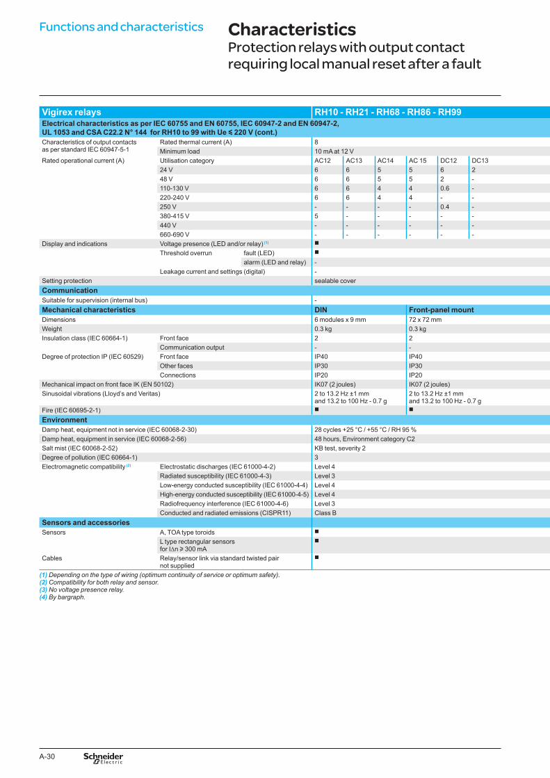
A-30
Functions and characteristics
Vigirex relays RH10 - RH21 - RH68 - RH86 - RH99Electrical characteristics as per IEC 60755 and EN 60755, IEC 60947-2 and EN 60947-2, UL 1053 and CSA C22.2 N° 144 for RH10 to 99 with Ue y 220 V (cont.)Characteristics of output contactsas per standard IEC 60947-5-1
Rated thermal current (A) 8Minimum load 10 mA at 12 V
Rated operational current (A) Utilisation category AC12 AC13 AC14 AC 15 DC12 DC1324 V 6 6 5 5 6 248 V 6 6 5 5 2 -110-130 V 6 6 4 4 0.6 -220-240 V 6 6 4 4 - -250 V - - - - 0.4 -380-415 V 5 - - - - -440 V - - - - - -660-690 V - - - - - -
Display and indications Voltage presence (LED and/or relay) (1) b
Threshold overrun fault (LED) b
alarm (LED and relay) -Leakage current and settings (digital) -
Setting protection sealable coverCommunicationSuitable for supervision (internal bus) -Mechanical characteristics DIN Front-panel mountDimensions 6 modules x 9 mm 72 x 72 mmWeight 0.3 kg 0.3 kgInsulation class (IEC 60664-1) Front face 2 2
Communication output - -Degree of protection IP (IEC 60529) Front face IP40 IP40
Other faces IP30 IP30Connections IP20 IP20
Mechanical impact on front face IK (EN 50102) IK07 (2 joules) IK07 (2 joules)Sinusoidal vibrations (Lloyd’s and Veritas) 2 to 13.2 Hz ±1 mm
and 13.2 to 100 Hz - 0.7 g2 to 13.2 Hz ±1 mm and 13.2 to 100 Hz - 0.7 g
Fire (IEC 60695-2-1) b b
EnvironmentDamp heat, equipment not in service (IEC 60068-2-30) 28 cycles +25 °C / +55 °C / RH 95 %Damp heat, equipment in service (IEC 60068-2-56) 48 hours, Environment category C2Salt mist (IEC 60068-2-52) KB test, severity 2Degree of pollution (IEC 60664-1) 3Electromagnetic compatibility (2) Electrostatic discharges (IEC 61000-4-2) Level 4
Radiated susceptibility (IEC 61000-4-3) Level 3Low-energy conducted susceptibility (IEC 61000-4-4) Level 4High-energy conducted susceptibility (IEC 61000-4-5) Level 4Radiofrequency interference (IEC 61000-4-6) Level 3Conducted and radiated emissions (CISPR11) Class B
Sensors and accessoriesSensors A, TOA type toroids b
L type rectangular sensorsfor IDn u 300 mA
b
Cables Relay/sensor link via standard twisted pairnot supplied
b
(1) Depending on the type of wiring (optimum continuity of service or optimum safety).(2) Compatibility for both relay and sensor.(3) No voltage presence relay.(4) By bargraph.
CharacteristicsProtection relays with output contact requiring local manual reset after a fault
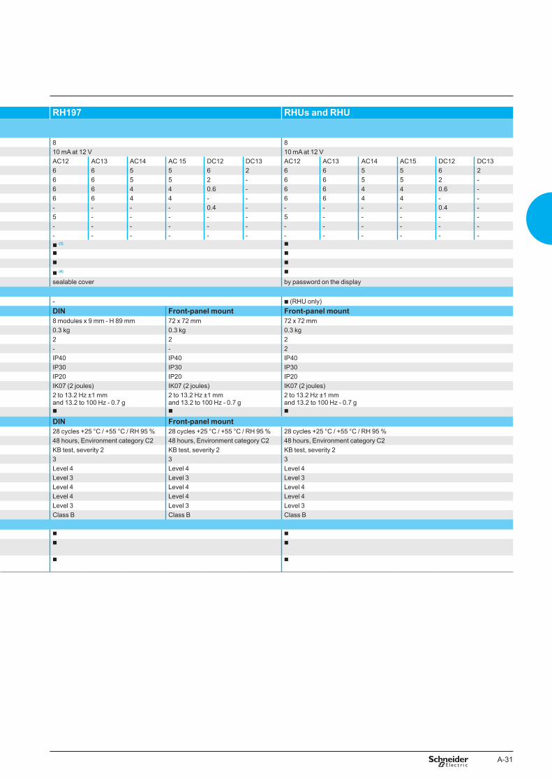
A-31
RH197 RHUs and RHU
8 810 mA at 12 V 10 mA at 12 VAC12 AC13 AC14 AC 15 DC12 DC13 AC12 AC13 AC14 AC15 DC12 DC136 6 5 5 6 2 6 6 5 5 6 26 6 5 5 2 - 6 6 5 5 2 -6 6 4 4 0.6 - 6 6 4 4 0.6 -6 6 4 4 - - 6 6 4 4 - -- - - - 0.4 - - - - - 0.4 -5 - - - - - 5 - - - - -- - - - - - - - - - - -- - - - - - - - - - - -b (3) b
b b
b b
b (4) b
sealable cover by password on the display
- b (RHU only)DIN Front-panel mount Front-panel mount8 modules x 9 mm - H 89 mm 72 x 72 mm 72 x 72 mm0.3 kg 0.3 kg 0.3 kg2 2 2- - 2IP40 IP40 IP40IP30 IP30 IP30IP20 IP20 IP20IK07 (2 joules) IK07 (2 joules) IK07 (2 joules)2 to 13.2 Hz ±1 mm and 13.2 to 100 Hz - 0.7 g
2 to 13.2 Hz ±1 mm and 13.2 to 100 Hz - 0.7 g
2 to 13.2 Hz ±1 mm and 13.2 to 100 Hz - 0.7 g
b b b
DIN Front-panel mount28 cycles +25 °C / +55 °C / RH 95 % 28 cycles +25 °C / +55 °C / RH 95 % 28 cycles +25 °C / +55 °C / RH 95 %48 hours, Environment category C2 48 hours, Environment category C2 48 hours, Environment category C2KB test, severity 2 KB test, severity 2 KB test, severity 23 3 3Level 4 Level 4 Level 4Level 3 Level 3 Level 3Level 4 Level 4 Level 4Level 4 Level 4 Level 4Level 3 Level 3 Level 3Class B Class B Class B
b b
b b
b b
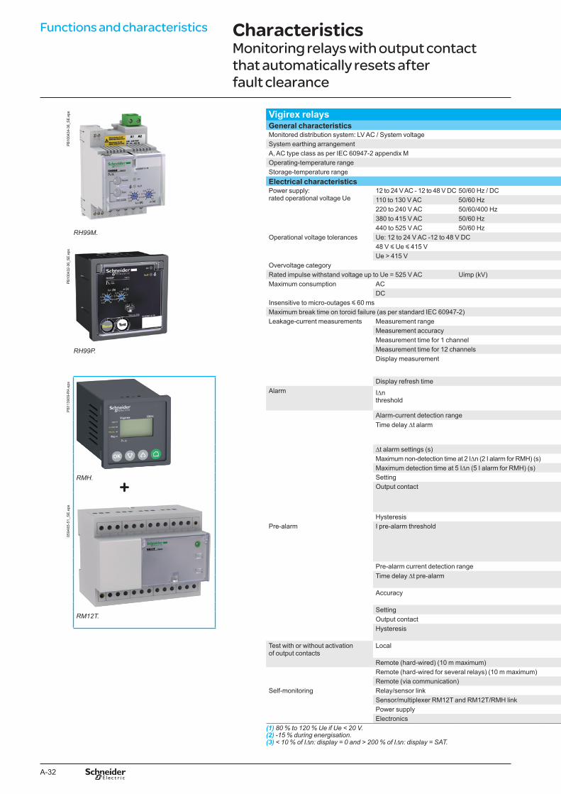
A-32
Functions and characteristics
PB10
0434
-36_
SE.e
ps
RH99M.
PB10
0432
-36_
SE.e
ps
RH99P.
PB
1139
09-R
4.ep
s
RMH.
0594
85-5
1_S
E.e
ps
RM12T.
Vigirex relaysGeneral characteristicsMonitored distribution system: LV AC / System voltageSystem earthing arrangementA, AC type class as per IEC 60947-2 appendix MOperating-temperature rangeStorage-temperature rangeElectrical characteristicsPower supply: rated operational voltage Ue
12 to 24 V AC - 12 to 48 V DC 50/60 Hz / DC110 to 130 V AC 50/60 Hz220 to 240 V AC 50/60/400 Hz380 to 415 V AC 50/60 Hz440 to 525 V AC 50/60 Hz
Operational voltage tolerances Ue: 12 to 24 V AC -12 to 48 V DC48 V y Ue y 415 VUe > 415 V
Overvoltage categoryRated impulse withstand voltage up to Ue = 525 V AC Uimp (kV)Maximum consumption AC
DCInsensitive to micro-outages y 60 msMaximum break time on toroid failure (as per standard IEC 60947-2)Leakage-current measurements Measurement range
Measurement accuracyMeasurement time for 1 channelMeasurement time for 12 channelsDisplay measurement
Display refresh timeAlarm IDn
threshold
Alarm-current detection rangeTime delay Dt alarm
Dt alarm settings (s)Maximum non-detection time at 2 IDn (2 I alarm for RMH) (s)Maximum detection time at 5 IDn (5 I alarm for RMH) (s)SettingOutput contact
HysteresisPre-alarm I pre-alarm threshold
Pre-alarm current detection rangeTime delay Dt pre-alarm
Accuracy
SettingOutput contactHysteresis
Test with or without activation of output contacts
Local
Remote (hard-wired) (10 m maximum)Remote (hard-wired for several relays) (10 m maximum)Remote (via communication)
Self-monitoring Relay/sensor linkSensor/multiplexer RM12T and RM12T/RMH linkPower supplyElectronics
(1) 80 % to 120 % Ue if Ue < 20 V.(2) -15 % during energisation.(3) < 10 % of IDn: display = 0 and > 200 % of IDn: display = SAT.
CharacteristicsMonitoring relays with output contact that automatically resets after fault clearance
+
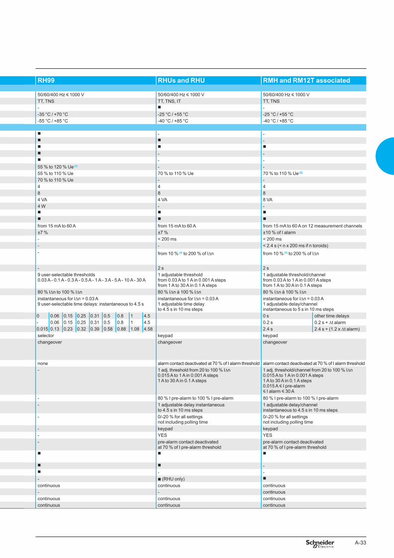
A-33
PB10
0434
-36_
SE.e
ps
RH99M.
PB10
0432
-36_
SE.e
ps
RH99P.
PB
1139
09-R
4.ep
s
RMH.
0594
85-5
1_S
E.e
ps
RM12T.
Vigirex relaysGeneral characteristicsMonitored distribution system: LV AC / System voltageSystem earthing arrangementA, AC type class as per IEC 60947-2 appendix MOperating-temperature rangeStorage-temperature rangeElectrical characteristicsPower supply: rated operational voltage Ue
12 to 24 V AC - 12 to 48 V DC 50/60 Hz / DC110 to 130 V AC 50/60 Hz220 to 240 V AC 50/60/400 Hz380 to 415 V AC 50/60 Hz440 to 525 V AC 50/60 Hz
Operational voltage tolerances Ue: 12 to 24 V AC -12 to 48 V DC48 V y Ue y 415 VUe > 415 V
Overvoltage categoryRated impulse withstand voltage up to Ue = 525 V AC Uimp (kV)Maximum consumption AC
DCInsensitive to micro-outages y 60 msMaximum break time on toroid failure (as per standard IEC 60947-2)Leakage-current measurements Measurement range
Measurement accuracyMeasurement time for 1 channelMeasurement time for 12 channelsDisplay measurement
Display refresh timeAlarm IDn
threshold
Alarm-current detection rangeTime delay Dt alarm
Dt alarm settings (s)Maximum non-detection time at 2 IDn (2 I alarm for RMH) (s)Maximum detection time at 5 IDn (5 I alarm for RMH) (s)SettingOutput contact
HysteresisPre-alarm I pre-alarm threshold
Pre-alarm current detection rangeTime delay Dt pre-alarm
Accuracy
SettingOutput contactHysteresis
Test with or without activation of output contacts
Local
Remote (hard-wired) (10 m maximum)Remote (hard-wired for several relays) (10 m maximum)Remote (via communication)
Self-monitoring Relay/sensor linkSensor/multiplexer RM12T and RM12T/RMH linkPower supplyElectronics
(1) 80 % to 120 % Ue if Ue < 20 V.(2) -15 % during energisation.(3) < 10 % of IDn: display = 0 and > 200 % of IDn: display = SAT.
RH99 RHUs and RHU RMH and RM12T associated
50/60/400 Hz y 1000 V 50/60/400 Hz y 1000 V 50/60/400 Hz y 1000 VTT, TNS TT, TNS, IT TT, TNS- b --35 °C / +70 °C -25 °C / +55 °C -25 °C / +55 °C-55 °C / +85 °C -40 °C / +85 °C -40 °C / +85 °C
b - -b b -b b bb - -b - -55 % to 120 % Ue (1) - -55 % to 110 % Ue 70 % to 110 % Ue 70 % to 110 % Ue (2)
70 % to 110 % Ue - -4 4 48 8 84 VA 4 VA 8 VA4 W - -b b bb b b
from 15 mA to 60 A from 15 mA to 60 A from 15 mA to 60 A on 12 measurement channels±7 % ±7 % ±10 % of I alarm- < 200 ms < 200 ms- - < 2.4 s (< n x 200 ms if n toroids)- from 10 % (3) to 200 % of IDn from 10 % (3) to 200 % of IDn
- 2 s 2 s9 user-selectable thresholds0.03 A - 0.1 A - 0.3 A - 0.5 A - 1 A - 3 A - 5 A - 10 A - 30 A
1 adjustable threshold from 0.03 A to 1 A in 0.001 A stepsfrom 1 A to 30 A in 0.1 A steps
1 adjustable threshold/channelfrom 0.03 A to 1 A in 0.001 A stepsfrom 1 A to 30 A in 0.1 A steps
80 % IDn to 100 % IDn 80 % IDn à 100 % IDn 80 % IDn à 100 % IDninstantaneous for IDn = 0.03 A9 user-selectable time delays: instantaneous to 4.5 s
instantaneous for IDn = 0.03 A1 adjustable time delayto 4.5 s in 10 ms steps
instantaneous for IDn = 0.03 A1 adjustable delay/channelinstantaneous to 5 s in 10 ms steps
0 0.06 0.15 0.25 0.31 0.5 0.8 1 4.5 0 s other time delays- 0.06 0.15 0.25 0.31 0.5 0.8 1 4.5 0.2 s 0.2 s + Dt alarm0.015 0.13 0.23 0.32 0.39 0.58 0.88 1.08 4.58 2.4 s 2.4 s + (1.2 x Dt alarm)selector keypad keypadchangeover changeover changeover
none alarm contact deactivated at 70 % of I alarm threshold alarm contact deactivated at 70 % of I alarm threshold- 1 adj. threshold from 20 to 100 % IDn
0.015 A to 1 A in 0.001 A steps1 A to 30 A in 0.1 A steps
1 adj. threshold/channel from 20 to 100 % IDn0.015 A to 1 A in 0.001 A steps1 A to 30 A in 0.1 A steps0.015 A y I pre-alarm y I alarm y 30 A
- 80 % I pre-alarm to 100 % I pre-alarm 80 % I pre-alarm to 100 % I pre-alarm- 1 adjustable delay instantaneous
to 4.5 s in 10 ms steps1 adjustable delay/channelinstantaneous to 4.5 s in 10 ms steps
- 0/-20 % for all settings not including polling time
0/-20 % for all settings not including polling time
- keypad keypad- YES YES- pre-alarm contact deactivated
at 70 % of I pre-alarm thresholdpre-alarm contact deactivatedat 70 % of I pre-alarm threshold
b b b
b b -b - -- b (RHU only) b
continuous continuous continuous- - continuouscontinuous continuous continuouscontinuous continuous continuous
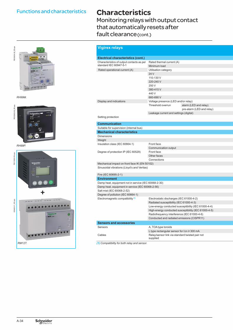
A-34
Functions and characteristicsPB
1004
34-3
6_SE
.eps
RH99M.
PB10
0432
-36_
SE.e
ps
RH99P.
PB
1139
09-R
4.ep
s05
9485
-51_
SE
.eps
RM12T.
Vigirex relays
Electrical characteristics (cont.)Characteristics of output contacts as per standard IEC 60947-5-1
Rated thermal current (A)Minimum load
Rated operational current (A) Utilisation category24 V110-130 V220-240 V250 V380-415 V440 V660-690 V
Display and indications Voltage presence (LED and/or relay)Threshold overrun alarm (LED and relay)
pre-alarm (LED and relay)Leakage current and settings (digital)
Setting protection
CommunicationSuitable for supervision (internal bus)Mechanical characteristicsDimensionsWeightInsulation class (IEC 60664-1) Front face
Communication outputDegree of protection IP (IEC 60529) Front face
Other facesConnections
Mechanical impact on front face IK (EN 50102)Sinusoidal vibrations (Lloyd’s and Veritas)
Fire (IEC 60695-2-1)EnvironmentDamp heat, equipment not in service (IEC 60068-2-30)Damp heat, equipment in service (IEC 60068-2-56)Salt mist (IEC 60068-2-52)Degree of pollution (IEC 60664-1)Electromagnetic compatibility (1) Electrostatic discharges (IEC 61000-4-2)
Radiated susceptibility (IEC 61000-4-3)Low-energy conducted susceptibility (IEC 61000-4-4)High-energy conducted susceptibility (IEC 61000-4-5)Radiofrequency interference (IEC 61000-4-6)Conducted and radiated emissions (CISPR11)
Sensors and accessoriesSensors A, TOA type toroids
L type rectangular sensor for IDn u 300 mACables Relay/sensor link via standard twisted pair not
supplied
(1) Compatibility for both relay and sensor.
RH99 RHUs and RHU RMH and RM12T associatedRMH RM12T
8 8 810 mA at 12 V 10 mA at 12 V 10 mA at 12 VAC12 AC13 AC14 AC15 DC12 DC13 AC12 AC13 AC14 AC15 DC12 DC13 AC12 AC13 AC14 AC15 DC12 DC136 6 5 5 6 2 6 6 5 5 6 2 6 6 5 5 6 26 6 4 4 0.6 - 6 6 4 4 0.6 - 6 6 4 4 0.6 -6 6 4 4 - - 6 6 4 4 - - 6 6 4 4 - -- - - - 0.4 - - - - - 0.4 - - - - - 0.4 -5 - - - - - 5 - - - - - 5 - - - - -- - - - - - - - - - - - - - - - - -- - - - - - - - - - - - - - - - - -b b b b LEDb (fault indication) b b -- b b -- b b -sealable cover by password on the display by password on the
display-
- b (RHU only) b
DIN Front-panel mount Front-panel mount Front-panel mount DIN6 modules x 9 mm 72 x 72 mm 72 x 72 mm 72 x 72 mm 12 modules x 9 mm0.3 kg 0.3 kg 0.3 kg 0.3 kg 0.42 kg2 2 2 2 -- - 2 2 -IP40 IP40 IP40 IP40 IP40IP30 IP30 IP30 IP30 IP30IP20 IP20 IP20 IP20 IP20IK07 (2 joules) IK07 (2 joules) IK07 (2 joules) IK07 (2 joules) IK07 (2 joules)2 to 13.2 Hz ±1 mm and 13.2 to 100 Hz – 0.7 g
2 to 13.2 Hz ±1 mm and 13.2 to 100 Hz – 0.7 g
2 to 13.2 Hz ±1 mm and 13.2 to 100 Hz - 0.7 g
2 to 13.2 Hz ±1 mm and 13.2 to 100 Hz - 0.7 g
2 to 13.2 Hz ±1 mm and 13.2 to 100 Hz - 0.7 g
b b b b b
28 cycles +25 °C / +55 °C / RH 95 % 28 cycles +25 °C / +55 °C / RH 95 % 28 cycles +25 °C / +55 °C / RH 95 %48 hours, Environment category C2 48 hours, Environment category C2 48 hours, Environment category C2KB test, severity 2 KB test, severity 2 KB test, severity 23 3 3Level 4 Level 4 Level 4Level 3 Level 3 Level 3Level 4 Level 4 Level 4Level 4 Level 4 Level 4Level 3 Level 3 Level 3Class B Class B Class B
b b b
b b b
b b b
CharacteristicsMonitoring relays with output contact that automatically resets after fault clearance (cont.)
+
A-35
PB10
0434
-36_
SE.e
ps
RH99M.
PB10
0432
-36_
SE.e
ps
RH99P.
PB
1139
09-R
4.ep
s05
9485
-51_
SE
.eps
RM12T.
Vigirex relays
Electrical characteristics (cont.)Characteristics of output contacts as per standard IEC 60947-5-1
Rated thermal current (A)Minimum load
Rated operational current (A) Utilisation category24 V110-130 V220-240 V250 V380-415 V440 V660-690 V
Display and indications Voltage presence (LED and/or relay)Threshold overrun alarm (LED and relay)
pre-alarm (LED and relay)Leakage current and settings (digital)
Setting protection
CommunicationSuitable for supervision (internal bus)Mechanical characteristicsDimensionsWeightInsulation class (IEC 60664-1) Front face
Communication outputDegree of protection IP (IEC 60529) Front face
Other facesConnections
Mechanical impact on front face IK (EN 50102)Sinusoidal vibrations (Lloyd’s and Veritas)
Fire (IEC 60695-2-1)EnvironmentDamp heat, equipment not in service (IEC 60068-2-30)Damp heat, equipment in service (IEC 60068-2-56)Salt mist (IEC 60068-2-52)Degree of pollution (IEC 60664-1)Electromagnetic compatibility (1) Electrostatic discharges (IEC 61000-4-2)
Radiated susceptibility (IEC 61000-4-3)Low-energy conducted susceptibility (IEC 61000-4-4)High-energy conducted susceptibility (IEC 61000-4-5)Radiofrequency interference (IEC 61000-4-6)Conducted and radiated emissions (CISPR11)
Sensors and accessoriesSensors A, TOA type toroids
L type rectangular sensor for IDn u 300 mACables Relay/sensor link via standard twisted pair not
supplied
(1) Compatibility for both relay and sensor.
RH99 RHUs and RHU RMH and RM12T associatedRMH RM12T
8 8 810 mA at 12 V 10 mA at 12 V 10 mA at 12 VAC12 AC13 AC14 AC15 DC12 DC13 AC12 AC13 AC14 AC15 DC12 DC13 AC12 AC13 AC14 AC15 DC12 DC136 6 5 5 6 2 6 6 5 5 6 2 6 6 5 5 6 26 6 4 4 0.6 - 6 6 4 4 0.6 - 6 6 4 4 0.6 -6 6 4 4 - - 6 6 4 4 - - 6 6 4 4 - -- - - - 0.4 - - - - - 0.4 - - - - - 0.4 -5 - - - - - 5 - - - - - 5 - - - - -- - - - - - - - - - - - - - - - - -- - - - - - - - - - - - - - - - - -b b b b LEDb (fault indication) b b -- b b -- b b -sealable cover by password on the display by password on the
display-
- b (RHU only) b
DIN Front-panel mount Front-panel mount Front-panel mount DIN6 modules x 9 mm 72 x 72 mm 72 x 72 mm 72 x 72 mm 12 modules x 9 mm0.3 kg 0.3 kg 0.3 kg 0.3 kg 0.42 kg2 2 2 2 -- - 2 2 -IP40 IP40 IP40 IP40 IP40IP30 IP30 IP30 IP30 IP30IP20 IP20 IP20 IP20 IP20IK07 (2 joules) IK07 (2 joules) IK07 (2 joules) IK07 (2 joules) IK07 (2 joules)2 to 13.2 Hz ±1 mm and 13.2 to 100 Hz – 0.7 g
2 to 13.2 Hz ±1 mm and 13.2 to 100 Hz – 0.7 g
2 to 13.2 Hz ±1 mm and 13.2 to 100 Hz - 0.7 g
2 to 13.2 Hz ±1 mm and 13.2 to 100 Hz - 0.7 g
2 to 13.2 Hz ±1 mm and 13.2 to 100 Hz - 0.7 g
b b b b b
28 cycles +25 °C / +55 °C / RH 95 % 28 cycles +25 °C / +55 °C / RH 95 % 28 cycles +25 °C / +55 °C / RH 95 %48 hours, Environment category C2 48 hours, Environment category C2 48 hours, Environment category C2KB test, severity 2 KB test, severity 2 KB test, severity 23 3 3Level 4 Level 4 Level 4Level 3 Level 3 Level 3Level 4 Level 4 Level 4Level 4 Level 4 Level 4Level 3 Level 3 Level 3Class B Class B Class B
b b b
b b b
b b b
A-36
Functions and characteristics05
9470
-27_
SE
.eps Sensors
Associated relaysMonitoring relaysProtection relays
UseNew installations and extensionsRenovation and extensionsGeneral characteristicsMonitored distribution systemInsulation level Ui
A type closed toroid: IA80. Closed sensorSplit sensorOperating-temperature range
PB
1146
68-R
4.ep
s Storage-temperature rangeDegree of protectionElectrical characteristicsTransformation ratioOvervoltage categoryRated impulse withstand voltage Uimp (kV)Sensor characteristicsRated operational current Ie (A)Conductor max. size per phase (mm² copper)Rated short-time withstand current Icw kA/0.5 sResidual short-circuit withstand current (IEC 60947-2)
IDw kA/0.5 sTOA type split toroid: TOA80.
Mechanical characteristicsType of sensorTA30 toroid
0594
76-4
8_S
E.e
ps PA50 toroidIA80 toroidMA120 toroidSA200 toroidGA300 toroidTOA80 toroidTOA120 toroidL1 rectangular sensorL2 rectangular sensorWiringWire size (mm²) for resistance R = 3 W
Type L rectangular sensor. 0.220.7511.5MountingClip-on mounting on rear of Vigirex relaySymmetrical DIN rail (horizontal or vertical mounting)Plain, slotted or profiled plateOn cableOn busbarsOpening / closing (number of operation)EnvironmentDamp heat, equipment not in service (IEC 60068-2-30)Damp heat, equipment in service (IEC 60068-2-56)Salt mist (IEC 60068-2-52)Degree of pollution (IEC 60664-1)
(1) With RH10, RH21, RH99, RH197, RHUs and RHU, IDn must be u �00 mA(2) From 0.5 to 2.5 mm².
CharacteristicsSensors
A-37
A type closed toroid TOA type split toroid L type rectangular sensor (1)
RH99, RMH RH99, RMH RH99, RMHRH10, RH21, RH68, RH86, RH99, RH197, RHUs and RHU RH10, RH21, RH68, RH86, RH99, RH197,
RHUs and RHURH10, RH21, RH68, RH86, RH99, RH197, RHUs and RHU
b - b
- b -
BT 50/60/400 Hz BT 50/60/400 Hz BT 50/60/400 Hz1000 V 1000 V 1000 Vb - b
- b --35 °C / +70 °C -35 °C / +70 °C -35 °C / +80 °C-55 °C / +85 °C -55 °C / +85 °C -55 °C / +100 °CIP30 (connections IP20) IP40 (connections IP20) IP30 (connections IP20)
1/1000 1/1000 1/10004 4 412 12 12TA30 PA50 IA80 MA120 SA200 GA300 TOA80 TOA120 L1 = 280 x 115 L2 = 470 x 16065 85 160 250 400 630 160 250 1600 320025 50 95 240 2 x 185 2 x 240 95 240 2 x 100 x 5 2 x 125 x 1025 50 50 85 85 85 50 85 100 10025 50 50 85 85 85 50 85 85 85
Dimensions ∅ (mm) Weight (kg) Dimensions ∅ (mm) Weight (kg) Inside dimensions (mm) Weight (kg)30 0.120 - - - -50 0.200 - - - -80 0.420 - - - -120 0.450 - - - -200 1.320 - - - -300 2.280 - - - -- - 80 0.9 - -- - 120 1.5 - -- - - - 280 x 115 11- - - - 470 x 160 20
Max. link length (m) Max. link length (m) Max. link length (m)18 18 -60 60 10 (2)
80 80 10 (2)
100 100 10 (2)
TA30, PA50 - -TA30, PA50, IA80, MA120 b -TA30, PA50, IA80, MA120, SA200 b -IA80, MA120, SA200, GA300 b b
- - b
- 10 maximum -
28 cycles +25 °C / +55 °C / RH 95 % 28 cycles +25 °C / +55 °C / RH 95 % 28 cycles +25 °C / +55 °C / RH 95 %48 hours, environment category C2 48 hours, environment category C2 48 hours, Environment category C2KB test, severity 2 KB test, severity 2 KB test, severity 23 3 4

A-38
B-1
Vigirex Installation recommendations
Functions and characteristics A-1
Relays and associated toroids B-2
Possible installation positions RH10-21-68-86-99M/P, RH197M/P, RHUs, RHU and RMH B-4A and TOA type toroids and rectangular sensors B-5
Connection Relays and sensors B-6Toroids and rectangular sensors B-8
Selection and installation instructions for toroids and rectangular sensors B-9
Dimensions and connection C-1Wiring diagrams D-1Additional characteristics E-1Catalogue numbers F-1
B-2
Installation recommandations
Residual-current protection relayModular format (DIN rail mount)
Vigirex RH10M
DB
1259
92.e
ps
Vigirex RH21M
DB
1259
93.e
ps
Vigirex RH99M
DB
1259
94.e
ps
RH10M. RH21M. RH�8M, RH8�M, RH99M.D
B40
3207
.eps
RH197M.
Modular format (with mounting accessories (1))
Vigirex RH10M
DB
1259
95.e
ps
Vigirex RH21M
DB
1259
96.e
ps
Vigirex RH99M
DB
1259
97.e
ps
RH10M. RH21M. RH99M.
(1) Supplied as option, to be clipped into relay for installation on a mounting plate.
Front-panel mount format
Vigirex RH197P
DB
1260
00.e
ps
Vigirex RH21P
DB
1260
01.e
ps
Vigirex RH99P
DB
1260
02.e
ps
RH10P. RH21P. RH8�P, RH99P
0.15
.25.5 1
2.5
5
IEC 60947-2 / M
.03.05.075
.1.1 .15.2
.3
x1
Vigirex RH197P
DB
1260
03.e
ps
VigirexRHUs
OK
Vigirex
RMU
DB
4190
65.e
ps
RH197P RHUs and RHU.
Relays and associated toroids
B-3
Monitoring relaysModular format
Mounting accessories (1)
Vigirex RH99M
DB
1260
05.e
ps
Vigirex RH99M
DB
1260
06.e
ps
Vigirex RH99M
DB
1260
07.e
ps
RH�8M, RH8�M, RH99M. RM12T. RH99M.(1) Supply as an option.
Front-panel mount format
Vigirex RH99P
DB
1260
02.e
ps
VigirexRHUs
OK
Vigirex
RMU
DB
4190
65.e
ps The Vigirex RMH always requires a RM12T multiplexer.
RH8�P, RH99P. RMH.
ToroidsClosed from 30 to 300 mm Split (for retrofit)
DB
1260
10.e
ps
DB
4037
97.e
ps
DB
4190
67.e
ps
A toroid. GA�00 toroid. TOA toroid.
Rectangular sensors
DB
1260
13.e
ps
DB
1260
14.e
ps
L1 = 280 x 115 mm. L2 = 470 x 1�0 mm.
Selection and compatibility of toroids and rectangular sensors
Type of sensor Type of Vigirex relayClosed toroid
Split toroid Rectangular sensor (1)
RH10-21-68-86-99, RH197,RHUs, RHU and RMH
TA30 - - b
PA50 TOA80 - b
IA80 - - b
MA120 TOA120 - b
SA200 - - b
GA300 - - b
- - L1 b
- - L2 b
(1) See restrictions in table below.
E toroids have not been included in the new range but are compatible with Vigirex relays subject to the following restrictions.Sensor restrictions table
RelaysSensors RH10, RH21, RH68, RH86, RH99, RH197,
RHUs, RHU and RMHA type closed toroid no restrictionsTOA type split toroid no restrictionsL type rectangular sensors IDn u 0.3 A
B-4
Installation recommandations
Possible installation positionsModular format
Vigirex RH10M
DB
1260
15.e
ps
Vigirex RH10M
DB
1260
16.e
ps
Vig
irex
RH
10M
DB
1260
17.e
ps
YES YES YES
Front-panel mount format
OK
Vigirex
RMU
OK
Vigirex
RMU
DB
4190
68.e
ps
OK
Vigirex
RMUOK
Vigire
xR
MU
DB
4190
70.e
ps
OK
Vigirex
RMU
DB
4190
71.e
ps
YES YES YES
Relay mounting possibilities
Vigirex RH10M
DB
1260
15.e
ps
Vigirex RH10M
DB
1260
22.e
ps Mounting of modular format relays RH10M-21M-68M-86M-99M-RH197MThe relay can be mounted in three ways:
b on a DIN rail (only this mounting for RH197M) b on a mounting plate using 3 M4 screws (not supplied) and 3 removable mounting
accessories (supplied).Mounting of front-panel mount relays RH10P-21P-86P-99P, RHUs, RHU and RMHNo special tools are required to mount the relay. Simply insert the device through the cutout. The size of the cutout complies with standard DIN 43700.Front panel thickness: 1 mm minimum / 2.5 mm maximum.The relay clips onto the panel.Mounting of relay RH197PNo tools are required to mount and secure the relay in position. Simply insert the device through the cutout and tighten the clamp by turning the knurled nut.The size of the cutout complies with standard DIN 43700.Front panel thickness: 1 mm minimum / 4 mm maximum.Mounting of RM12T multiplexerThe multiplexer must always be mounted on a DIN rail.
DIN rail. Mounting plate.
OK
Vigirex
DB
4190
69.e
ps
Vigirex RH10P
DB
4031
45.e
ps
Front-panel mount. RHUs, RHU and RMH details. Front-panel mount. RH10P, RH21P, RH8�P and RH99P detail.
Vigirex RM12T
DB
1260
25.e
ps
Vigirex RH10P
DB
4031
46.e
ps
RM12T: DIN rail only. Front-panel mount. RH197P detail.
Possible installation positionsRH10-21-68-86-99M/P, RH197M/P, RHUs, RHU and RMH
B-5
Toroid mounting possibilitiesOn DIN rail (TA30, PA50, IA80 and MA120) using supplied accessories
DB
4039
00.e
ps
DB
4039
01.e
ps
DB
4037
96.e
ps
Accessory.
On a plate (TA30, PA50, IA80, MA120, SA200, GA300, TOA80 and TOA120) or bracket
Screws not supplied
DB
1260
31.e
ps Screw Ø4 Screw Ø5D
B12
6030
.eps TA30 IA80
PA50 MA120SA200GA300TOA80TOA120
Clipped on the back of the relay (TA30 and PA50)
Vigirex RH10M
DB
1260
32.e
ps
Tied to cables (IA80, MA120, SA200 and GA300), cable-ties not suppliedCable-ties with 9 mm maximum width and 1.5 mm maximum thickness
DB
1260
33.e
ps
DB
1260
34.e
ps
Tied to cables (rectangular sensors)
DB
1260
35.e
ps
DB
1260
36.e
ps
On bars with chocks (rectangular sensors)
DB
1260
37.e
ps
DB
1260
38.e
ps
A and TOA type toroids and rectangular sensors
DB
4190
77.e
ps
B-6
Installation recommandations
Product, terminal or screw
Cable type Terminal capacity (mm2) Conduct. size
Stripping Tightening torque
Rigid Flexible Flexible with ferrule AWG Rigid/flexiblemin. max. min. max. min. max. (mm) (inch) (N.m) (In-lbs)
RH10M, RH21M, RH68M, RH86M and RH99M11, 14 0.2 4 0.2 2.5 0.25 2.5 24-12 8 .31 0.6 0.067831, 32, 34 0.2 4 0.2 2.5 0.25 2.5 24-12 8 .31 0.6 0.0678A1, A2 0.2 2.5 0.2 2.5 0.25 2.5 24-12 7 .27 0.6 0.0678T1, T2 twisted pair 0.14 1.5 0.14 1 0.25 0.5 26-16 5 .19 0.25 0.0282525, 26, 27 3 twisted wires L<10 m 0.14 1.5 0.14 1 0.25 0.5 26-16 5 .19 0.25 0.02825RH197M
A1, A2 0.2 2.5 0.2 2.5 0.25 2.5 24-12 7 .27 0.6 0.067831, 32, 34 0.2 2.5 0.2 2.5 0.25 2.5 24-12 7 .27 0.6 0.067825-26, 27-28 0.2 2.5 0.2 2.5 0.25 2.5 24-12 7 .27 0.6 0.0678T1, T2 0.2 2.5 0.2 2.5 0.25 2.5 24-12 7 .27 0.6 0.067841, 42, 44 0.2 2.5 0.2 2.5 0.25 2.5 24-12 7 .27 0.6 0.0678RH10P, RH21P, RH86P, RH99P
11, 14 or 41, 44 0.2 2.5 0.2 2.5 0.25 2.5 24-12 7 .27 0.6 0.067831, 32, 34 0.2 2.5 0.2 2.5 0.25 2.5 24-12 7 .27 0.6 0.0678A1, A2 0.2 2.5 0.2 2.5 0.25 2.5 24-12 7 .27 0.6 0.0678T1, T2 twisted pair 0.2 2.5 0.2 2.5 0.25 2.5 24-12 7 .27 0.6 0.067825, 26, 27 3 twisted wires L<10 m 0.2 2.5 0.2 2.5 0.25 2.5 24-12 7 .27 0.6 0.0678RH197P
11, 14 0.2 2.5 0.2 2.5 0.25 2.5 24-12 7 .27 0.6 0.067831, 32, 34 0.2 2.5 0.2 2.5 0.25 2.5 24-12 7 .27 0.6 0.0678A1, A2 0.2 2.5 0.2 2.5 0.25 2.5 24-12 7 .27 0.6 0.0678T1, T2 twisted pair 0.2 2.5 0.2 2.5 0.25 2.5 24-12 7 .27 0.6 0.067825, 26, 27 3 twisted wires L>10 m 0.2 2.5 0.2 2.5 0.25 2.5 24-12 7 .27 0.6 0.0678RHUs and RHU
A1, A2 0.2 2.5 0.2 2.5 0.25 2.5 22-12 6 .23 0.5 0.056511, 14 0.2 2.5 0.2 2.5 0.25 2.5 22-12 6 .23 0.5 0.056531, 32, 34 0.2 2.5 0.2 2.5 0.25 2.5 22-12 6 .23 0.5 0.056541, 44 0.2 2.5 0.2 2.5 0.25 2.5 22-12 6 .23 0.5 0.0565T1, T2 twisted pair 0.2 2.5 0.2 2.5 0.25 2.5 22-12 6 .23 0.5 0.056525, 26, 27 3 twisted wires L<10 m 0.2 2.5 0.2 2.5 0.25 2.5 22-12 6 .23 0.5 0.0565Bus (1) 24 V, 0 V twisted pair 0.2 2.5 0.2 2.5 0.25 2.5 22-12 6 .23 0.5 0.0565
-, + twisted pair 0.2 2.5 0.2 2.5 0.25 2.5 22-12 6 .23 0.5 0.0565RMH
A1, A2 0.2 2.5 0.2 2.5 0.25 2.5 22-12 6 .23 0.5 0.056511, 14 0.2 2.5 0.2 2.5 0.25 2.5 22-12 6 .23 0.5 0.056531, 32, 34 0.2 2.5 0.2 2.5 0.25 2.5 22-12 6 .23 0.5 0.056541, 44 0.2 2.5 0.2 2.5 0.25 2.5 22-12 6 .23 0.5 0.056521, 22 twisted pair L<10 m 0.2 2.5 0.2 2.5 0.25 2.5 22-12 6 .23 0.5 0.056523, 24 twisted pair L<10 m 0.2 2.5 0.2 2.5 0.25 2.5 22-12 6 .23 0.5 0.0565Bus 24 V, 0 V twisted pair 0.2 2.5 0.2 2.5 0.25 2.5 22-12 6 .23 0.5 0.0565
-, + twisted pair 0.2 2.5 0.2 2.5 0.25 2.5 22-12 6 .23 0.5 0.0565RM12T
12 toroid connections 1 to 12 and 15 to 20
1 twisted pair/toroid L < 10 m
0.2 2.5 0.2 2.5 0.25 2.5 22-12 6 .23 0.5 0.0565
21, 22 twisted pair L<10 m 0.2 2.5 0.2 2.5 0.25 2.5 22-12 6 .23 0.5 0.056523, 24 twisted pair L<10 m 0.2 2.5 0.2 2.5 0.25 2.5 22-12 6 .23 0.5 0.056525, 26 0.2 2.5 0.2 2.5 0.25 2.5 22-12 6 .23 0.5 0.0565Toroid and sensors
TA30 and PA50Ø 30 to 50 mmconnectors supplied
twisted Cu/Al 0.2 2.5 0.2 2.5 0.2 1.5 24-14 6 .23 0.5 0.0565
IA80 to GA300Ø 80 to 300 mm twisted Cu/Al
0.2 2.5 0.2 2.5 0.2 1.5 24-1 6 .23 0.5 0.0565
TOA80 - TOA120 Ø 5 mm round lugs note supplied:
0.2 2.5 0.2 2.5 0.2 1.5 24-14 6 .23 0.6 5.2
S1, S2 twisted Cu/Al - - - - - - - - - 3 0.339Mounting on a mounting plate and DIN Rail clip
- - - - - - - - - 3.5 31
L1, L2: M1, M2 twisted pair L<10 m 0.5 2.5 0.5 2.5 0.5 2.5 20-14 8 to 9 .33 - -(1) RHU only.
ConnectionRelays and sensors
B-7
Connection of relays
DB
1260
21.e
ps Modular format
Déconnecter A1-A2avant test diélectrique
Disconnect A1-A2before dielectric test
A1 A2
220 / 240 VAC50 / 60 / 400 Hz
Vigirex RH99M
RH99MVigirex
DB
4031
48.e
ps(1) See table page B-�.
Front-panel mount format
T
DB
4031
49.e
ps
Connection of toroidsTA30 and PA50 closed toroids (connectors supplied) IA80, MA120, SA200 and GA300 closed toroids
DB
4031
50.e
ps
DB
4031
51.e
ps
(1) See table page B-�. (1) See table page B-�.
B-8
Installation recommandations
Connection of toroids (cont.)TOA80 and TOA120 split toroids (Ø 5 mm round lugs not supplied)
DB
4190
78.e
ps
(1) See table page B-�.
Connection of rectangular sensors and conductor layout
L1: frame 280 x 115 mm L2: frame 470 x 160 mmBusbars with 70 mm spacing Busbars with 115 mm spacing
DB
1260
62.e
ps M1 M2 M3
DB
1260
63.e
ps
2 bars 50 x 10 mm (1�00 A) The neutral can be located on the right or the left.
4 bars 100 x 5 mm (�200 A) The neutral can be located on the right or the left.
(1) See table page B-�.
DB
1260
64.e
ps M1 M2 M3
DB
1260
65.e
ps
2 bars 100 x 5 mm (1�00 A)The neutral can be located on the right or the left.
4 bars 125 x 5 mm (�200 A). The neutral can be located on the right or the left.
(1) See table page B-�.
DB
4031
54.e
ps
4 cables 240 mm2 (1�00 A)(1) See table page B-�.
Note: connect M1 and M2 with Vigirex.
ConnectionToroids and rectangular sensors
B-9
Cable layout
DB
4031
55.e
ps
DB
4031
56.e
ps
DB
4031
57.e
ps
Centre the cables within the toroid toroid Ø u 2 x total cable Ø
DB
4031
58.e
ps
DB
4031
78.e
ps
Do not bend cables near the toroids Single-phase or three-phase loads with several cables per phase
DB
4031
59.e
ps
DB
4031
79.e
ps
DB
4031
80.e
ps
1 cable per phase. Several cables per phase.
Do not bend cables near the sensors
DB
4031
81.e
ps
Selection of toroids according to circuit power3P + N copper cablesRated operational current (Ie) Max. cross-section/phase Toroids
65 A 16 mm2 TA3085 A 25 mm2 PA50160 A 70 mm2 IA80 or TOA80
Do not bend bars near the sensors 250 A 120 mm2 MA120 or TOA120
DB
4031
82.e
ps 400 A 2 x 185 mm2 SA200630 A 2 x 240 mm2 GA3001600 A 4 x 240 mm2 L1
Selection of rectangular sensors according to circuit power3P + N copper barsRated operational current (Ie) Max. cross-section/phase Sensors
1600 A 2 bars 50 x 10 mm2 L1Note: Y u 25 cm for 280 x 115 mm sensor. Note: Y u �0 cm for 470 x 1�0 mm sensor.
2 bars 100 x 5 mm2
3200 A 4 bars 100 x 5 mm2 L24 bars 125 x 5 mm2
Selection and installation instructions for toroids and rectangular sensors

B-10
Installation recommandations
Immunisation with respect to false zero-sequence currents (tested at 6 In as per IEC 60947-2 annex M)The addition of a shielding ring prevents nuisance tripping with TA30, PA50, IA80 and MA120 toroids for the settings indicated in table below
For circuits with high transient currents (6 In) Sensor In Maximum cross-section per phase IDn
Magneticring
DB
1179
45.e
ps With shielding ringTA30 65 A 16 mm2 30 mAPA50 85 A 25 mm2 30 mAIA80 160 A 70 mm2 100 mAMA120 250 A 120 mm2 100 mAWithout shielding ring
SA200 400 A 2 x 185 mm2 300 mAGA300 630 A 2 x 240 mm2 300 mATOA80 85 A 95 mm2 100 mATOA120 250 A 240 mm2 1 AL1 1600 A 4 x 240 mm2
or 2 copper bars 100 x 5 mm2500 mA
L2 3200 A 2 copper bars 125 x 10 mm2 500 mA
Connection between Vigrex relays and sensorsVigirex relays must be connected to the sensors as indicated:
Cross-section (Cu) Maximum length
Vigirex RH99M
DB
4032
55.e
ps
Toroids0.22 mm2 (1) 18 m0.75 mm2 (1) 60 m1 mm2 (1) 80 m1.5 mm2 (1) 100 mRectangular sensors0.5 mm2 min. / 2.5 mm2 max. 10 m(1) Wire size for resistance R maximum = � W.
Cable typeStandard twisted pair (not to be run alongside power cables).
In highly disturbed environments:
WiringShielded twisted pair (not to be run alongside power cables).The shielding must be earthed at both ends by connection to the equipotential bonding circuit.The cable between the toroid and the relay should be as short as possible.If this is not sufficient, use a transformer with high frequency (HF) shielding.
Vigirex RH99M
DB
4032
56.e
ps
Auxiliary power supply via external transformer.
Selection and installation instructions for toroids and rectangular sensors
C-1
Vigirex Dimensions and connection
Functions and characteristics A-1Installation recommendations B-1
Dimensions RH10M, RH21M, RH68M, RH86M, RH99M and RH197M relays C-2RH10P, RH21P, RH86P, RH99P, RH197P, RHUs, RHU, RMH and RM12T relays C-3A-type closed toroids C-4TOA split toroids and rectangular sensors C-5
Wiring diagrams D-1Additional characteristics E-1Catalogue numbers F-1
1.3
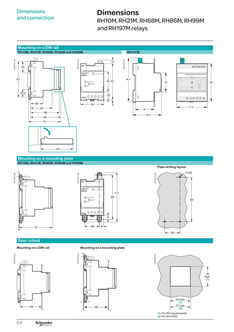
C-2
Dimensions and connection
Mounting on a DIN railRH10M, RH21M, RH68M, RH86M and RH99M RH197M
DB
4031
47.e
ps
RH10MVigirex
DB
1260
39.e
ps
71.2
8998.7
45
45
65.8
DB
4032
05.e
ps
Mounting on a mounting plateRH10M, RH21M, RH68M, RH86M and RH99M
Plate drilling layout
DB
1260
40.e
ps
RH10MVigirex
DB
1260
41.e
ps
DB
1260
42.e
ps
Door cutout
Mounting on a DIN rail Mounting on a mounting plate
DB
1260
43.e
ps
DB
1260
44.e
ps
72 max.(2)
DB
4149
35.e
ps
(1) For IP4 requirements.(2) For RH197M.
DimensionsRH10M, RH21M, RH68M, RH86M, RH99M and RH197M relays
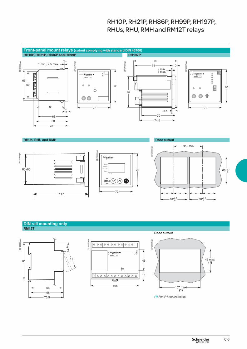
C-3
Front-panel mount relays (cutout complying with standard DIN 43700)RH10P, RH21P, RH86P and RH99P RH197P
DB
1010
80.e
ps
RH10PVigirex
DB
1260
46.e
ps
DB
1017
28.e
ps
RH197PVigirex
DB
1260
47.e
ps
RHUs, RHU and RMH Door cutout
DB
1260
50.e
ps
DIN rail mounting onlyRM12T
Door cutout
DB
1260
51.e
ps
RM12TVigirex
DB
1260
52.e
ps
DB
1260
53.e
ps
(1) For IP4 requirements.
RH10P, RH21P, RH86P, RH99P, RH197P, RHUs, RHU, RMH and RM12T relays
OK
DB
4190
85.e
ps
65x65
117
DB
4190
84.e
ps

C-4
TA30 and PA50 toroids
Secured to the back of the relay
DB
1260
54.e
ps
RH10MVigirex
DB
1260
55.e
ps
Type ØA B C D E F G H J KTA30 30 31 60 53 82 59 - 13 97 50PA50 50 45 88 66 108 86 20 14 98 60
IA80, MA120, SA200 and GA300 toroids
IA80 and MA120 SA200 and GA300
DB
1260
56.e
ps
DB
1260
57.e
ps
Type ØA B C D E F G H J KIA80 80 122 44 150 80 55 40 126 65 35MA120 118 164 39 190 140 - - 163 125 30SA200 196 256 46 274 120 90 60 254 104 37GA300 291 360 46 390 120 90 60 369 104 37
Dimensions (cont.)A-type closed toroids
Dimensions and connection
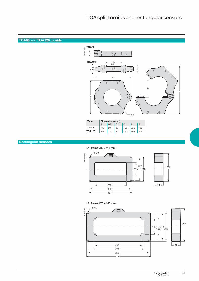
C-5
TOA80 and TOA120 toroids
Type Dimensions (mm)A ØB C D E F
TOA80 177 80 28 108 235 156TOA120 225 120 50 150 303 205
Rectangular sensors
L1: frame 280 x 115 mm
DB
1260
60.e
ps
L2: frame 470 x 160 mm
DB
1260
08.e
ps
TOA split toroids and rectangular sensors
TOA120
391.54
TOA80
C
Ø B
A
F
DE
C
1003.94
DB
4190
79.e
ps

C-6

D-1
Vigirex Wiring diagrams
Functions and characteristics A-1Installation recommendations B-1Dimensions and connection C-1
Wiring diagrams RH10, RH21, RH68, RH86 and RH99M RH10, RH21, RH86 and RH99P D-2RH86, RH99 monitor D-4RH197M with MX shunt release D-5RH197M with MN undervoltage release D-6RH197P with MX shunt release D-7RH197P with MN undervoltage release D-8RHUs and RHU D-9RMH D-10Communication bus, test and remote reset functions, power supply D-11
Additional characteristics E-1Catalogue numbers F-1
1.3
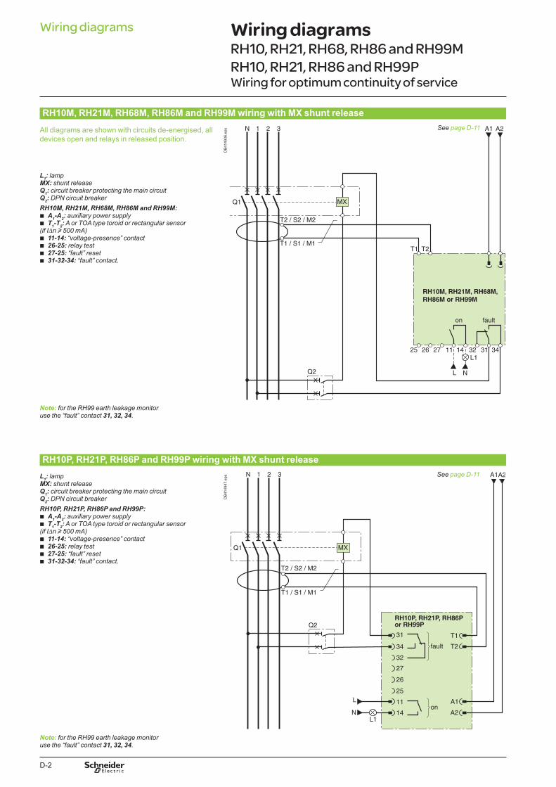
D-2
RH10M, RH21M, RH68M, RH86M and RH99M wiring with MX shunt release
All diagrams are shown with circuits de-energised, all devices open and relays in released position.
See page D-11
DB
4149
36.e
ps
L1: lampMX: shunt releaseQ1: circuit breaker protecting the main circuitQ2: DPN circuit breakerRH10M, RH21M, RH68M, RH86M and RH99M:
b A1-A2: auxiliary power supply b T1-T2: A or TOA type toroid or rectangular sensor
(if IDn u 500 mA) b 11-14: “voltage-presence” contact b 26-25: relay test b 27-25: “fault” reset b 31-32-34: “fault” contact.
Note: for the RH99 earth leakage monitor use the “fault” contact 31, 32, 34.
RH10P, RH21P, RH86P and RH99P wiring with MX shunt releaseL1: lampMX: shunt releaseQ1: circuit breaker protecting the main circuitQ2: DPN circuit breakerRH10P, RH21P, RH86P and RH99P:
b A1-A2: auxiliary power supply b T1-T2: A or TOA type toroid or rectangular sensor
(if IDn u 500 mA) b 11-14: “voltage-presence” contact b 26-25: relay test b 27-25: “fault” reset b 31-32-34: “fault” contact.
See page D-11
DB
4149
47.e
ps
Note: for the RH99 earth leakage monitor use the “fault” contact 31, 32, 34.
Wiring diagrams Wiring diagramsRH10, RH21, RH68, RH86 and RH99M RH10, RH21, RH86 and RH99PWiring for optimum continuity of service
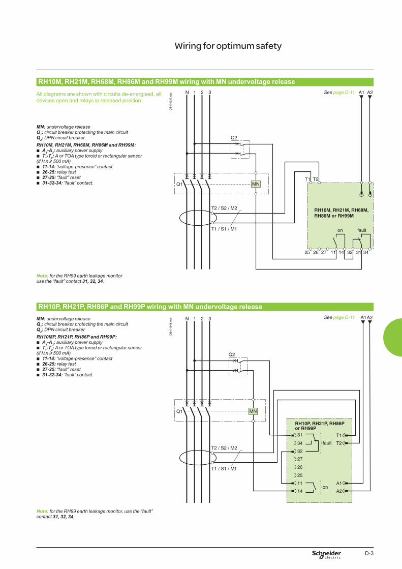
D-3
RH10M, RH21M, RH68M, RH86M and RH99M wiring with MN undervoltage release
All diagrams are shown with circuits de-energised, all devices open and relays in released position.
DB
4149
37.e
ps See page D-11
MN: undervoltage releaseQ1: circuit breaker protecting the main circuitQ2: DPN circuit breakerRH10M, RH21M, RH68M, RH86M and RH99M:
b A1-A2: auxiliary power supply b T1-T2: A or TOA type toroid or rectangular sensor
(if IDn u 500 mA) b 11-14: “voltage-presence” contact b 26-25: relay test b 27-25: “fault” reset b 31-32-34: “fault” contact.
Note: for the RH99 earth leakage monitor use the “fault” contact 31, 32, 34.
RH10P, RH21P, RH86P and RH99P wiring with MN undervoltage releaseMN: undervoltage releaseQ1: circuit breaker protecting the main circuitQ2: DPN circuit breakerRH10MP, RH21P, RH86P and RH99P:
b A1-A2: auxiliary power supply b T1-T2: A or TOA type toroid or rectangular sensor
(if IDn u 500 mA) b 11-14: “voltage-presence” contact b 26-25: relay test b 27-25: “fault” reset b 31-32-34: “fault” contact.
DB
4149
48.e
ps See page D-11
Note: for the RH99 earth leakage monitor, use the “fault” contact 31, 32, 34.
Wiring for optimum safety
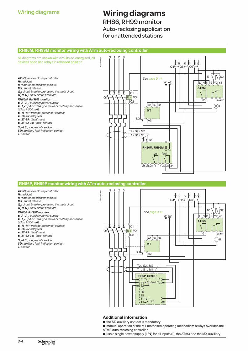
D-4
RH86M, RH99M monitor wiring with ATm auto-reclosing controller
All diagrams are shown with circuits de-energised, all devices open and relays in released position.
DB
4149
38.e
ps
See page D-11ATm3: auto-reclosing controllerH: red lightMT: motor mechanism moduleMX: shunt releaseQ1: circuit breaker protecting the main circuitQ4 to Q6: DPN circuit breakersRH86M, RH99M monitor:
b A1-A2: auxiliary power supply b T1-T2: A or TOA type toroid or rectangular sensor
(if IDn u 500 mA) b 11-14: “voltage-presence” contact b 26-25: relay test b 27-25: “fault” reset b 31-32-34: “fault” contact
S1 et S2: single-pole switchSD: auxiliary fault indication contactT: sensor.
RH86P, RH99P monitor wiring with ATm auto-reclosing controllerATm3: auto-reclosing controllerH: red lightMT: motor mechanism moduleMX: shunt releaseQ1: circuit breaker protecting the main circuitQ4 to Q6: DPN circuit breakersRH86P, RH99P monitor:
b A1-A2: auxiliary power supply b T1-T2: A or TOA type toroid or rectangular sensor
(if IDn u 500 mA) b 11-14: “voltage-presence” contact b 26-25: relay test b 27-25: “fault” reset b 31-32-34: “fault” contact
S1 et S2: single-pole switchSD: auxiliary fault indication contactT: sensor.
DB
4149
39.e
ps
See page D-11
Additional information b the SD auxiliary contact is mandatory b manual operation of the MT motorised operating mechanism always overides the
ATm3 auto-reclosing controller b use a single power supply (L/N) for all inputs (I), the ATm3 and the MX auxiliary.
Wiring diagramsRH86, RH99 monitorAuto-reclosing application for unattended stations
Wiring diagrams

D-5
RH197M wiring for optimum continuity of service
All diagrams are shown with circuits de-energised, all devices open and relays in released position.
M
28
Reset Test
Alarm Fault
42
A2 A1
H1
DB
4149
40.e
ps
See page D-11
Switch setting:
DB
4032
61.e
ps
L1: lamp and audio alarmMX: shunt releaseQ1: circuit breaker protecting the main circuitQ2: DPN circuit breakerRH197M:
b A1-A2: auxiliary power supply b T1-T2: A or TOA type toroid or rectangular sensor
(if IDn y 500 mA) b 41-44: “alarm contact” b 26-25: relay test b 27-25: “fault” reset b 31-32-34: “fault” contact
RH197M wiring for optimum safety
All diagrams are shown with circuits de-energised, all devices open and relays in released position. A2 A1
M
28
Reset Test
Alarm Fault
42
A2 A1
H1
DB
4149
41.e
ps
Switch setting:
DB
4032
62.e
ps
WarningThe supply for A1-A2 must be different from that of the MX shunt release.
L1: lamp and audio alarmMX: shunt releaseQ1: circuit breaker protecting the main circuitQ2: DPN circuit breakerRH197M:
b A1-A2: auxiliary power supply b T1-T2: A or TOA type toroid or rectangular sensor
(if IDn y 500 mA) b 41-44: “alarm contact” b 26-25: relay test b 27-25: “fault” reset b 31-32-34: “fault” contact.
RH197M with MX shunt release
See page D-11

D-6
RH197M wiring for optimum continuity of service
All diagrams are shown with circuits de-energised, all devices open and relays in released position.
M
28
Reset Test
Alarm
A2 A1
H1
A2 A1
42
FaultD
B40
3785
.eps See page D-11
Switch setting:
DB
4032
61.e
ps
L1: lamp and audio alarmMN: undervoltage releaseQ1: circuit breaker protecting the main circuitQ2: DPN circuit breakerRH197M:
b A1-A2: auxiliary power supply b T1-T2: A or TOA type toroid or rectangular sensor
(if IDn < 500 mA) b 41-44: “alarm contact” b 26-25: relay test b 27-25: “fault” reset b 31-32-34: “fault” contact.
RH197M wiring for optimum safety
All diagrams are shown with circuits de-energised, all devices open and relays in released position.
See page D-11
M
28
Reset Test
Alarm Fault
A2 A1
H1
A2 A1
42
DB
4037
86.e
ps
Switch setting:
DB4
0326
2.ep
s
L1: lamp and audio alarmMN: undervoltage releaseQ1: circuit breaker protecting the main circuitQ2: DPN circuit breakerRH197M:
b A1-A2: auxiliary power supply b T1-T2: A or TOA type toroid or rectangular sensor
(if IDn y 500 mA) b 41-44: “alarm contact” b 26-25: relay test b 27-25: “fault” reset b 31-32-34: “fault” contact.
Wiring diagramsRH197M with MN undervoltage release
Wiring diagrams
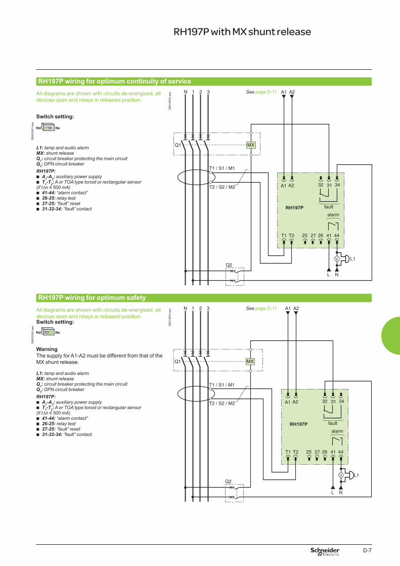
D-7
RH197P wiring for optimum continuity of service
All diagrams are shown with circuits de-energised, all devices open and relays in released position.
DB
4149
42.e
ps See page D-11
Switch setting:
DB
4032
61.e
ps
L1: lamp and audio alarmMX: shunt releaseQ1: circuit breaker protecting the main circuitQ2: DPN circuit breakerRH197P:
b A1-A2: auxiliary power supply b T1-T2: A or TOA type toroid or rectangular sensor
(if IDn y 500 mA) b 41-44: “alarm contact” b 26-25: relay test b 27-25: “fault” reset b 31-32-34: “fault” contact
RH197P wiring for optimum safety
All diagrams are shown with circuits de-energised, all devices open and relays in released position.
DB
4149
43.e
ps See page D-11
Switch setting:
DB
4032
62.e
ps
WarningThe supply for A1-A2 must be different from that of the MX shunt release.
L1: lamp and audio alarmMX: shunt releaseQ1: circuit breaker protecting the main circuitQ2: DPN circuit breakerRH197P:
b A1-A2: auxiliary power supply b T1-T2: A or TOA type toroid or rectangular sensor
(if IDn y 500 mA) b 41-44: “alarm contact” b 26-25: relay test b 27-25: “fault” reset b 31-32-34: “fault” contact.
RH197P with MX shunt release

D-8
RH197P wiring for optimum continuity of service
All diagrams are shown with circuits de-energised, all devices open and relays in released position.
DB
4149
44.e
ps See page D-11
Switch setting:
DB
4032
61.e
ps
L1: lamp and audio alarmMN: undervoltage releaseQ1: circuit breaker protecting the main circuitQ2: DPN circuit breakerRH197P:
b A1-A2: auxiliary power supply b T1-T2: A or TOA type toroid or rectangular sensor
(if IDn < 500 mA) b 41-44: “alarm contact” b 26-25: relay test b 27-25: “fault” reset b 31-32-34: “fault” contact.
RH197P wiring for optimum safety
All diagrams are shown with circuits de-energised, all devices open and relays in released position.
DB
4149
45.e
ps See page D-11
Switch setting:
DB
4032
62.e
ps
L1: lamp and audio alarmMN: undervoltage releaseQ1: circuit breaker protecting the main circuitQ2: DPN circuit breakerRH197P:
b A1-A2: auxiliary power supply b T1-T2: A or TOA type toroid or rectangular sensor
(if IDn y 500 mA) b 41-44: “alarm contact” b 26-25: relay test b 27-25: “fault” reset b 31-32-34: “fault” contact.
Wiring diagramsRH197P with MN undervoltage release
Wiring diagrams
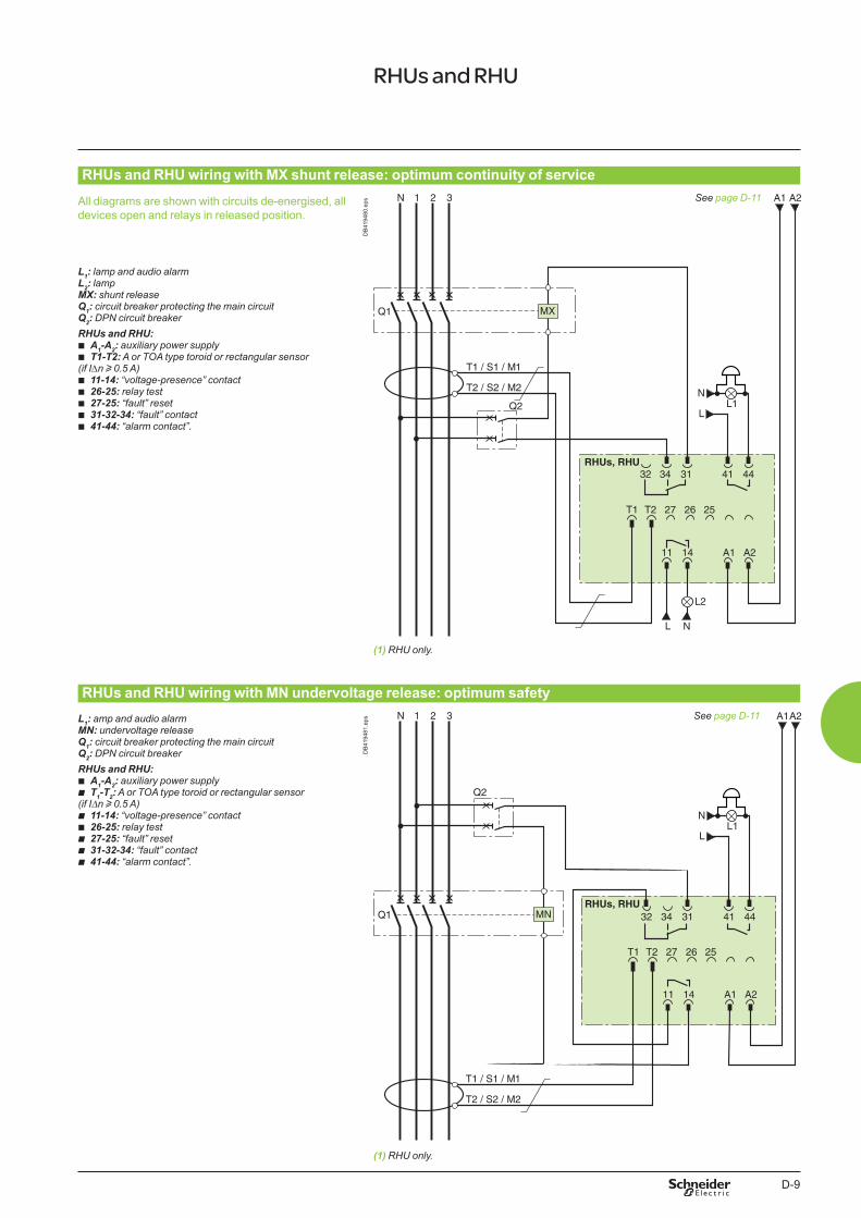
D-9
RHUs and RHU wiring with MX shunt release: optimum continuity of service
All diagrams are shown with circuits de-energised, all devices open and relays in released position.
DB
4194
80.e
ps See page D-11
L1: lamp and audio alarmL2: lampMX: shunt releaseQ1: circuit breaker protecting the main circuitQ2: DPN circuit breakerRHUs and RHU:
b A1-A2: auxiliary power supply b T1-T2: A or TOA type toroid or rectangular sensor
(if IDn u 0.5 A) b 11-14: “voltage-presence” contact b 26-25: relay test b 27-25: “fault” reset b 31-32-34: “fault” contact b 41-44: “alarm contact”.
(1) RHU only.
RHUs and RHU wiring with MN undervoltage release: optimum safetyL1: amp and audio alarmMN: undervoltage releaseQ1: circuit breaker protecting the main circuitQ2: DPN circuit breakerRHUs and RHU:
b A1-A2: auxiliary power supply b T1-T2: A or TOA type toroid or rectangular sensor
(if IDn u 0.5 A) b 11-14: “voltage-presence” contact b 26-25: relay test b 27-25: “fault” reset b 31-32-34: “fault” contact b 41-44: “alarm contact”.
DB
4194
81.e
ps See page D-11
(1) RHU only.
RHUs and RHU
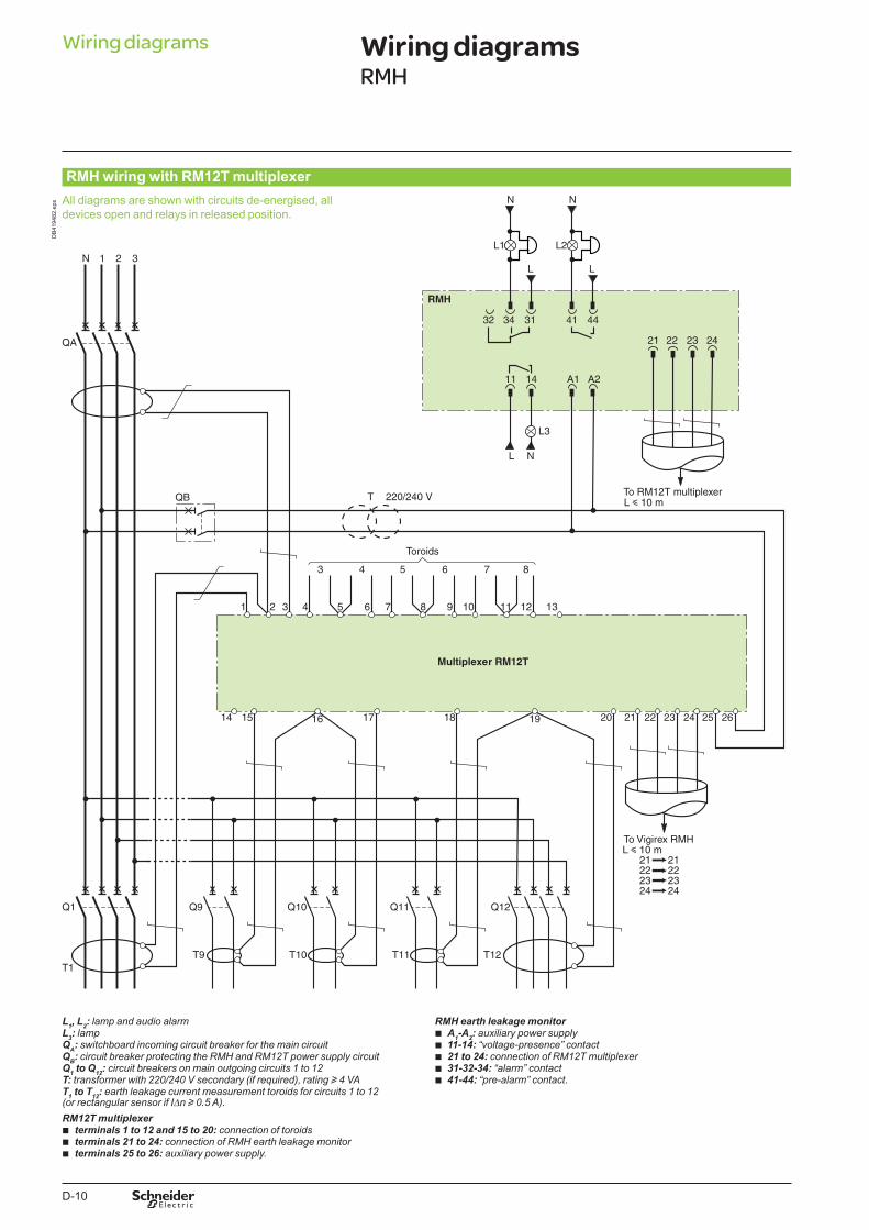
D-10
RMH wiring with RM12T multiplexer
DB
4194
82.e
ps
L1, L2: lamp and audio alarmL3: lampQA: switchboard incoming circuit breaker for the main circuitQB: circuit breaker protecting the RMH and RM12T power supply circuitQ1 to Q12: circuit breakers on main outgoing circuits 1 to 12T: transformer with 220/240 V secondary (if required), rating u 4 VAT1 to T12: earth leakage current measurement toroids for circuits 1 to 12(or rectangular sensor if IDn u 0.5 A).RM12T multiplexer
b terminals 1 to 12 and 15 to 20: connection of toroids b terminals 21 to 24: connection of RMH earth leakage monitor b terminals 25 to 26: auxiliary power supply.
RMH earth leakage monitor b A1-A2: auxiliary power supply b 11-14: “voltage-presence” contact b 21 to 24: connection of RM12T multiplexer b 31-32-34: “alarm” contact b 41-44: “pre-alarm” contact.
Wiring diagrams Wiring diagramsRMH
All diagrams are shown with circuits de-energised, all devices open and relays in released position.
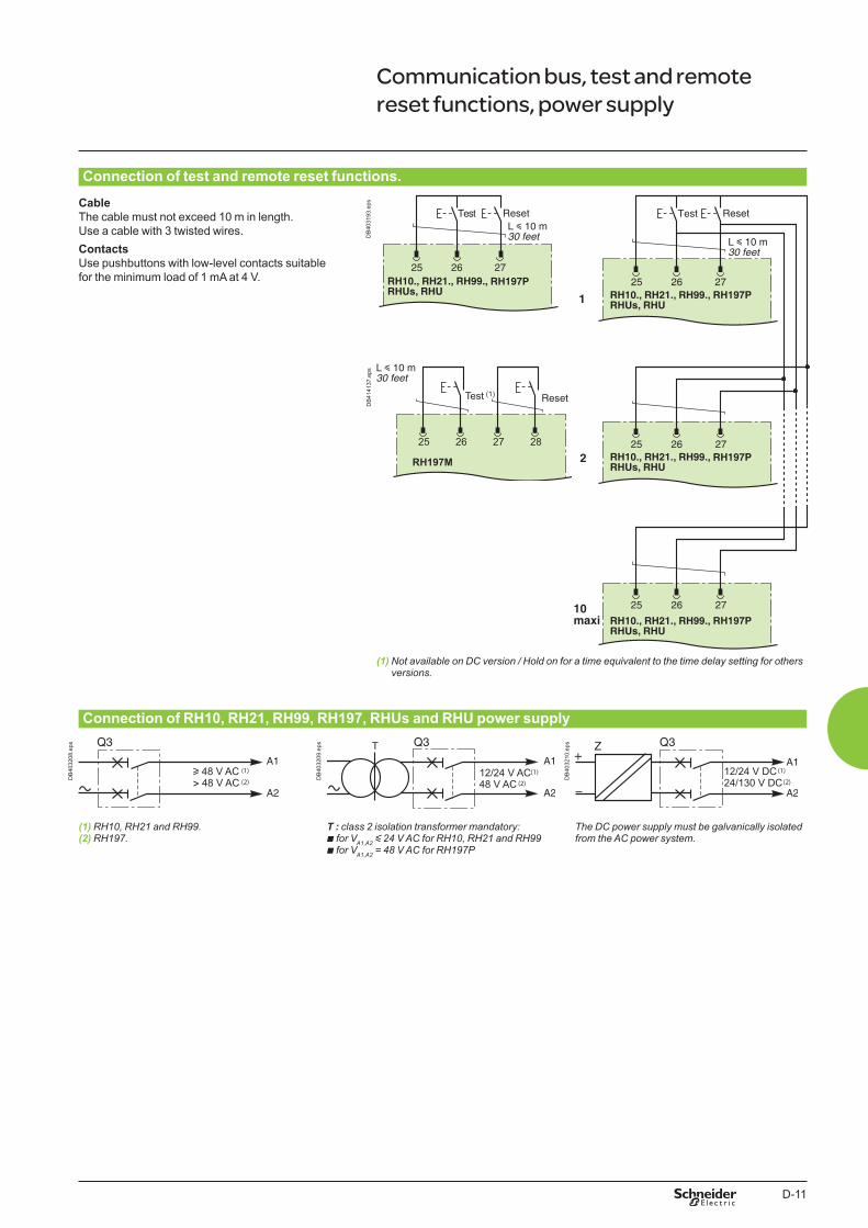
D-11
Connection of test and remote reset functions.
CableThe cable must not exceed 10 m in length. Use a cable with 3 twisted wires.ContactsUse pushbuttons with low-level contacts suitable for the minimum load of 1 mA at 4 V.
DB
4031
93.e
ps
(1) Not available on DC version / Hold on for a time equivalent to the time delay setting for others versions.
Connection of RH10, RH21, RH99, RH197, RHUs and RHU power supply
u 48 V AC (1)> 48 V AC (2)D
B40
3208
.eps
12/24 V AC (1)48 V AC (2)
DB
4032
09.e
ps
12/24 V DC (1)24/130 V DC (2)D
B40
3210
.eps
(1) RH10, RH21 and RH99.(2) RH197.
T : class 2 isolation transformer mandatory: b for VA1,A2 y 24 V AC for RH10, RH21 and RH99b for VA1,A2 = 48 V AC for RH197P
The DC power supply must be galvanically isolated from the AC power system.
Communication bus, test and remote reset functions, power supply
28272625
RH197M
Test (1)
DB
4141
37.e
ps

D-12
E-1
Vigirex Additional characteristics
Functions and characteristics A-1Installation recommendations B-1Dimensions and connection C-1Wiring diagrams D-1
Definitions and glossary E-2
Protection using Vigirex RCDs Protection of persons E-4System earthing arrangements E-7Protection of property: fire hazards E-10Disturbances in distribution systems E-12
Vigirex devices RCD operating principle E-14Residual-current measurements E-16Implementation E-24Applications E-28Questions and answers E-34
Leakage-current monitoring using RCDs E-37
Tripping curves and frequency filtering RH10, RH21, RH68, RH86 and RH99 E-43RH197M E-44RH197P E-45RHUs and RHU E-46
Catalogue numbers F-1
E-2
Earth: the conducting mass of the Earth, whose electric potential at any point is conventionally taken as zero.
Earth electrode: conductive part that can be incorporated in a particular conductive environment, for example concrete or coke in electrical contact with earth.
Earth-fault current: current flowing to earth due to an insulation fault.
Earthing resistance or in fact the “overall earthing resistance”: resistance between the main earthing terminal (terminal or bar to which the PE protective conductors are connected) and earth.
Earth-leakage current: current flowing from the live parts to earth or extraneous conductive parts in the absence of an insulation fault.
Equipotential bonding: electrical connection putting various exposed conductive parts and extraneous conductive parts at a substantially equal potential.
Exposed conductive part: a conductive part which can readily be touched and which is not normally live, but which may become live under fault conditions.
Intentional leakage current: current flowing to earth or extraneous conductive parts via intentionally installed components (resistors or capacitors), in the absence of an insulation fault.
Isolated system: system with an autonomous supply of power, not connected to utility power.
Natural leakage current: current flowing to earth or extraneous conductive parts via the insulation, in the absence of an insulation fault.
Protective conductor PE: a conductor required by some measures for protection against electric shock for electrically connecting any of the following parts: exposed conductive parts, extraneous conductive parts, main earthing terminal, earth electrode, earthed point of the source or artificial neutral, metallic parts of the building structure that are not part of an electrical device, protected by equipotential bonding, if they are simultaneously accessible.
Residual current: vector sum of the instantaneous values of the current in all the live conductors of a circuit at a given point in an electrical installation.
Zero volt (reference): measurement reference point for differences in potential (voltage measurements, often in monitoring circuits).
Additional characteristics Definitions and glossary
E-3
Acronym/ French
Acronym/English
Definition
DDR RCD Residual-current device. A mechanical device or set of devices intended to open contacts when the residual current reaches a set value under the specified conditions.
DPCC SCPD Short-circuit protective device.dv/dt Variation in the voltage as a function of time
(term generally reserved for fast variations, on the order of 1000 V/ms).IGBT IGBT Insulated gate bipolar transistor.IT IT In the IT system, all the live parts are either isolated from earth or connected to earth at one point via
an impedance. The exposed conductive parts of the electrical installation are earthed.Filtre RFI RFI
RFI filter An RFI filter limits radio-frequency disturbances.RFI: Radio-frequency interference.
SLT System earthing arrangement
System earthing arrangement (sometimes referred to as the earthing system).
TN TN In the TN system, a point in the supply system is directly connected to earth. The exposed conductive parts of the electrical installation are connected to this point via protective conductors.
TN-C TN-C The TN-C system is a TN system in which the neutral and protection functions are combined in a single conductor (PEN) throughout the installation.
TN-C-S TN-C-S The TN-C-S system is a TN system in which the neutral and protection functions are combined in a single conductor (PEN) in a part of the installation (upstream of the TN-S system).
TN-S TN-S The TN-S system is a TN system in which a protective conductor separate from the neutral is used throughout the installation.
TT TT In the TT system, a point in the supply system is directly connected to earth. The exposed conductive parts of the electrical installation are connected to earth electrodes that are electrically separate from that for the supply system.
CEM / EM EMC / EM Electromagnetic compatibility (EMC) is the aptitude of a device or system to operate in its electromagnetic (EM) environment satisfactorily and without itself producing unacceptable electromagnetic disturbances for its environment.
GFP GFP Ground fault protection System used to measure zero-sequence currents that flow if a fault occurs in the TN-S system (used in the United States).
NEC NEC National electrical code Installation standard published by an association in the United States.
THDI THDI Total harmonic distortion of current.Valeur efficace RMS Root mean square value.
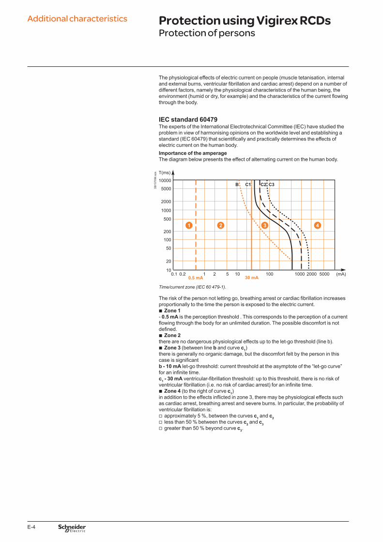
E-4
The physiological effects of electric current on people (muscle tetanisation, internal and external burns, ventricular fibrillation and cardiac arrest) depend on a number of different factors, namely the physiological characteristics of the human being, the environment (humid or dry, for example) and the characteristics of the current flowing through the body.
IEC standard 60479The experts of the International Electrotechnical Committee (IEC) have studied the problem in view of harmonising opinions on the worldwide level and establishing a standard (IEC 60479) that scientifically and practically determines the effects of electric current on the human body.Importance of the amperageThe diagram below presents the effect of alternating current on the human body.
0.1 0.20.5 mA
DB
1070
96.e
ps
Time/current zone (IEC 60 479-1).
The risk of the person not letting go, breathing arrest or cardiac fibrillation increases proportionally to the time the person is exposed to the electric current.
b Zone 1- 0.5 mA is the perception threshold . This corresponds to the perception of a current flowing through the body for an unlimited duration. The possible discomfort is not defined.
b Zone 2there are no dangerous physiological effects up to the let-go threshold (line b).
b Zone 3 (between line b and curve c1)there is generally no organic damage, but the discomfort felt by the person in this case is significantb - 10 mA let-go threshold: current threshold at the asymptote of the “let-go curve” for an infinite time.c1 - 30 mA ventricular-fibrillation threshold: up to this threshold, there is no risk of ventricular fibrillation (i.e. no risk of cardiac arrest) for an infinite time.
b Zone 4 (to the right of curve c1)in addition to the effects inflicted in zone 3, there may be physiological effects such as cardiac arrest, breathing arrest and severe burns. In particular, the probability of ventricular fibrillation is:
v approximately 5 %, between the curves c1 and c2 v less than 50 % between the curves c2 and c3 v greater than 50 % beyond curve c3.
Additional characteristics Protection using Vigirex RCDsProtection of persons
E-5
Importance of the current frequencyStandard IEC 60479-1 § 3 and -2 § 4 defines the sensitivity of the human body to fibrillation depending on the frequency of the current.Current thresholds depending on the frequencyFrequency (Hz) Perception (mA) Let-go (mA) Fibrillation (mA)
DC 2 - 10050 0.5 10 40100 0.5 10 80300 0.6 12 1801000 1 17 5603000 2 23 -5000 4 32 -10000 6 50 ->10000 100 - -
Installation standard IEC 60364Touch voltage/ disconnecting timeStandard IEC 60479 defines the effects of an electric current flowing through the human body.
b The installation standards IEC 60364 (NF C 15-100 in France), in chapter 4-41, establish the mandatory safety rules for low-voltage electrical installations:
v by translating the current / exposure time values in the previous curve into a set of touch voltage / contact time values that must not be exceeded. The values depend on the environment conditions (humid or dry) in the installation
v by defining the techniques and operational diagrams to be used to avoid (or manage) the dangerous voltages resulting from an insulation fault.
b They define the dangerous limit values UL for the touch voltage: v UL = 50 V for a dry environment (generally the case). b As a result, there are two operating modes in a low-voltage installation: v operation with an operational voltage under the limit value, i.e. no particular action
is required if an insulation fault occurs v operation with an operational voltage greater than the touch voltage (generally the
case), where, if an insulation fault occurs, the dangerous part of the installation must be automatically disconnected within a given time limit (see the table below).Maximum disconnecting time of protection device(s) (according to table 41A of standard IEC 60364)Ph-N voltage (V) AC current DC current
U0 y 50 V 5 s 5 s50 V < U0 y 120 V 0.8 s 5 s120 V < U0 y 230 V 0.4 s 5 s230 V < U0 y 400 V 0.2 s 0.4 sU0 > 400 V 0.1 s 0.1 s
The installation standards of specific countries interpret this table according to the applicable system earthing arrangement.

E-6
Type of contactThe standards and regulations distinguish two types of potentially dangerous contacts and indicate the corresponding protection techniques.
DB
1069
93.e
ps b Direct contact: contact of a person with live conductors (phase or neutral) or with conductive parts that are habitually live.Protection against direct contact is normally provided by insulation of the live parts using barriers, screens or enclosures (as per standard IEC 60364-4-41 or NF C 15-100). These systems are preventive in nature and may fail. That is why additional protection is installed, in the form of a high-sensitivity RCD that automatically breaks the circuit. The operating threshold is set to 30 mA for AC current (IEC 60364-4-41 or NF C 15-100) and 60 mA for DC current.The sensitivity of RC protection devices, designed to limit the current flowing through the body to a maximum of 30 mA, provides a very high level of safety and maintains a good continuity of service.
Direct contact.
Detection
DB
1070
97.e
ps Comparison between 10 mA and 30 mA sensitivitiesAn RCD set to 10 mA will trip somewhat more quickly than an RCD set to 30 mA. But a 10 mA setting significantly increases the risk of disturbing the continuity of service due to nuisance tripping caused by natural leakage currents.
Comparison between 10 mA and �0 mA.
DB
1069
95.e
ps b Indirect contact: contact of a person with exposed conductive parts that are normally not live, but may become live by accident. This situation is due to failure of the insulation for a device or conductor, resulting in an insulation fault. The electrical risk depends on the touch voltage between the exposed conductive parts of the faulty equipment and earth or other exposed conductive parts located nearby.The design of protection devices based on the physiological thresholds stipulated in IEC standard 60479 and complying with the rules defined in standard IEC 60364 has made it possible to create safe electrical installations.
Indirect contact.
Additional characteristics Protection using Vigirex RCDsProtection of persons
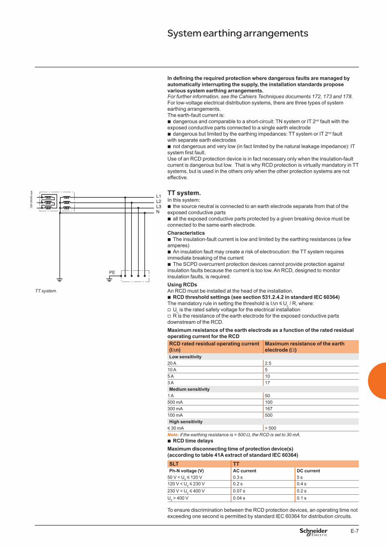
E-7
In defining the required protection where dangerous faults are managed by automatically interrupting the supply, the installation standards propose various system earthing arrangements.For further information, see the Cahiers Techniques documents 172, 17� and 178.For low-voltage electrical distribution systems, there are three types of system earthing arrangements. The earth-fault current is:
b dangerous and comparable to a short-circuit: TN system or IT 2nd fault with the exposed conductive parts connected to a single earth electrode
b dangerous but limited by the earthing impedances: TT system or IT 2nd fault with separate earth electrodes
b not dangerous and very low (in fact limited by the natural leakage impedance): IT system first fault.Use of an RCD protection device is in fact necessary only when the insulation-fault current is dangerous but low. That is why RCD protection is virtually mandatory in TT systems, but is used in the others only when the other protection systems are not effective.
L1L2L3N
PE
DB
1260
68.e
ps TT system.In this system:
b the source neutral is connected to an earth electrode separate from that of the exposed conductive parts
b all the exposed conductive parts protected by a given breaking device must be connected to the same earth electrode.Characteristics
b The insulation-fault current is low and limited by the earthing resistances (a few amperes)
b An insulation fault may create a risk of electrocution: the TT system requires immediate breaking of the current
b The SCPD overcurrent protection devices cannot provide protection against insulation faults because the current is too low. An RCD, designed to monitor insulation faults, is required.Using RCDsAn RCD must be installed at the head of the installation.
b RCD threshold settings (see section 531.2.4.2 in standard IEC 60364)The mandatory rule in setting the threshold is IDn y UL / R, where:
v UL is the rated safety voltage for the electrical installation v R is the resistance of the earth electrode for the exposed conductive parts
downstream of the RCD.Maximum resistance of the earth electrode as a function of the rated residual operating current for the RCD
TT system.
RCD rated residual operating current (IDn)
Maximum resistance of the earth electrode (W)
Low sensitivity20 A 2.510 A 55 A 103 A 17Medium sensitivity
1 A 50500 mA 100300 mA 167100 mA 500High sensitivity
y 30 mA > 500Note: if the earthing resistance is > 500 W, the RCD is set to �0 mA.
b RCD time delaysMaximum disconnecting time of protection device(s) (according to table 41A extract of standard IEC 60364)SLT TTPh-N voltage (V) AC current DC current
50 V < U0 y 120 V 0.3 s 5 s120 V < U0 y 230 V 0.2 s 0.4 s230 V < U0 y 400 V 0.07 s 0.2 sU0 > 400 V 0.04 s 0.1 s
To ensure discrimination between the RCD protection devices, an operating time not exceeding one second is permitted by standard IEC 60364 for distribution circuits.
System earthing arrangements
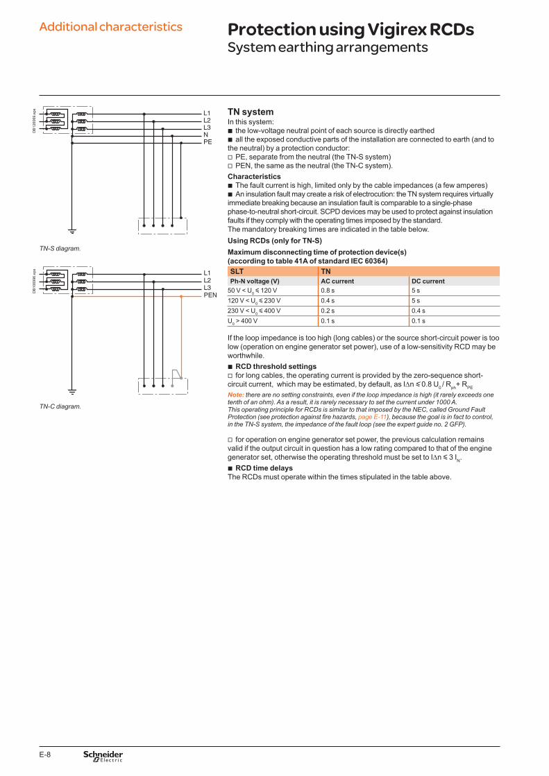
E-8
DB
1260
69.e
ps TN systemIn this system:
b the low-voltage neutral point of each source is directly earthed b all the exposed conductive parts of the installation are connected to earth (and to
the neutral) by a protection conductor: v PE, separate from the neutral (the TN-S system) v PEN, the same as the neutral (the TN-C system).
Characteristics b The fault current is high, limited only by the cable impedances (a few amperes) b An insulation fault may create a risk of electrocution: the TN system requires virtually
immediate breaking because an insulation fault is comparable to a single-phase phase-to-neutral short-circuit. SCPD devices may be used to protect against insulation faults if they comply with the operating times imposed by the standard.The mandatory breaking times are indicated in the table below.Using RCDs (only for TN-S)Maximum disconnecting time of protection device(s) (according to table 41A of standard IEC 60364)
TN-S diagram.
DB
1069
96.e
ps SLT TNPh-N voltage (V) AC current DC current
50 V < U0 y 120 V 0.8 s 5 s120 V < U0 y 230 V 0.4 s 5 s230 V < U0 y 400 V 0.2 s 0.4 sU0 > 400 V 0.1 s 0.1 s
If the loop impedance is too high (long cables) or the source short-circuit power is too low (operation on engine generator set power), use of a low-sensitivity RCD may be worthwhile.
b RCD threshold settings v for long cables, the operating current is provided by the zero-sequence short-
circuit current, which may be estimated, by default, as IDn y 0.8 U0 / Rph+ RPE
Note: there are no setting constraints, even if the loop impedance is high (it rarely exceeds one tenth of an ohm). As a result, it is rarely necessary to set the current under 1000 A. This operating principle for RCDs is similar to that imposed by the NEC, called Ground Fault Protection (see protection against fire hazards, page E-11), because the goal is in fact to control, in the TN-S system, the impedance of the fault loop (see the expert guide no. 2 GFP).
v for operation on engine generator set power, the previous calculation remains valid if the output circuit in question has a low rating compared to that of the engine generator set, otherwise the operating threshold must be set to IDn y 3 IN.
b RCD time delaysThe RCDs must operate within the times stipulated in the table above.
TN-C diagram.
Additional characteristics Protection using Vigirex RCDsSystem earthing arrangements
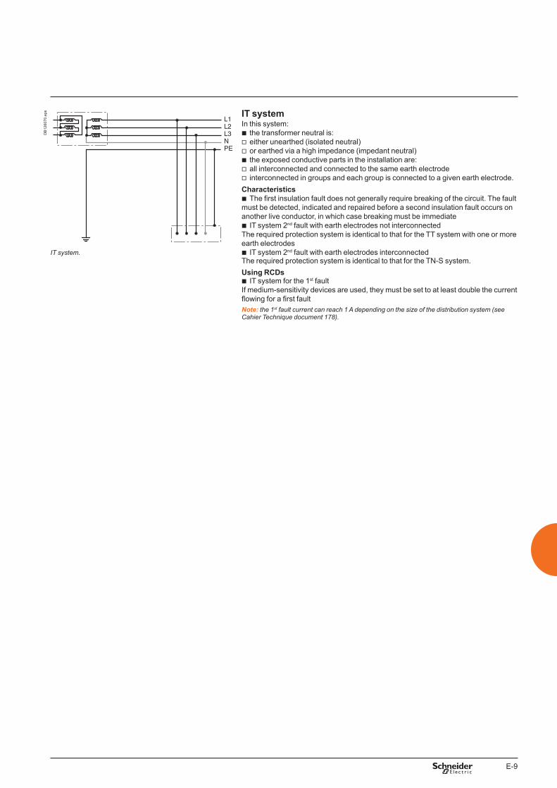
E-9
L1L2L3NPE
DB
1260
70.e
ps IT systemIn this system:
b the transformer neutral is: v either unearthed (isolated neutral) v or earthed via a high impedance (impedant neutral) b the exposed conductive parts in the installation are: v all interconnected and connected to the same earth electrode v interconnected in groups and each group is connected to a given earth electrode.
Characteristics b The first insulation fault does not generally require breaking of the circuit. The fault
must be detected, indicated and repaired before a second insulation fault occurs on another live conductor, in which case breaking must be immediate
b IT system 2nd fault with earth electrodes not interconnected The required protection system is identical to that for the TT system with one or more earth electrodes
b IT system 2nd fault with earth electrodes interconnectedThe required protection system is identical to that for the TN-S system.Using RCDs
b IT system for the 1st fault If medium-sensitivity devices are used, they must be set to at least double the current flowing for a first faultNote: the 1st fault current can reach 1 A depending on the size of the distribution system (see Cahier Technique document 178).
IT system.
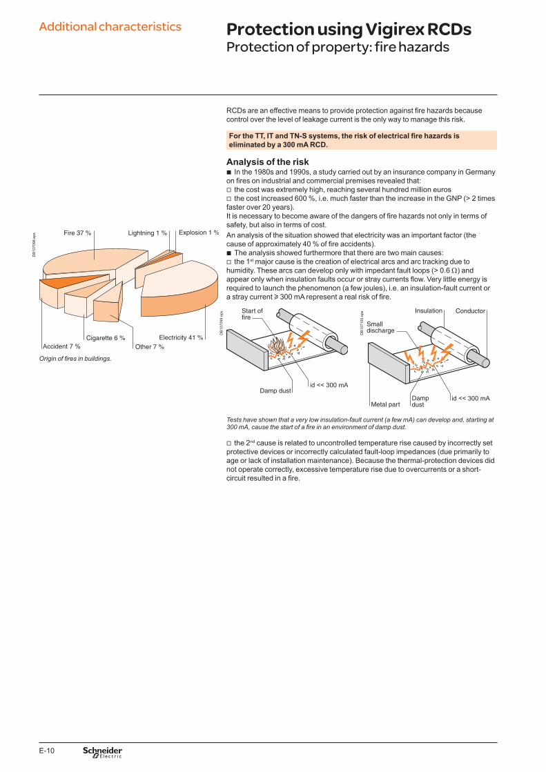
E-10
RCDs are an effective means to provide protection against fire hazards because control over the level of leakage current is the only way to manage this risk.
For the TT, IT and TN-S systems, the risk of electrical fire hazards is eliminated by a 300 mA RCD.
Analysis of the risk b In the 1980s and 1990s, a study carried out by an insurance company in Germany
on fires on industrial and commercial premises revealed that: v the cost was extremely high, reaching several hundred million euros v the cost increased 600 %, i.e. much faster than the increase in the GNP (> 2 times
faster over 20 years).It is necessary to become aware of the dangers of fire hazards not only in terms of safety, but also in terms of cost.
DB
1070
98.e
ps An analysis of the situation showed that electricity was an important factor (the cause of approximately 40 % of fire accidents).
b The analysis showed furthermore that there are two main causes: v the 1st major cause is the creation of electrical arcs and arc tracking due to
humidity. These arcs can develop only with impedant fault loops (> 0.6 W) and appear only when insulation faults occur or stray currents flow. Very little energy is required to launch the phenomenon (a few joules), i.e. an insulation-fault current or a stray current u 300 mA represent a real risk of fire.
DB
1070
99.e
ps
DB
1071
00.e
psOrigin of fires in buildings.
Tests have shown that a very low insulation-fault current (a few mA) can develop and, starting at 300 mA, cause the start of a fire in an environment of damp dust.
v the 2nd cause is related to uncontrolled temperature rise caused by incorrectly set protective devices or incorrectly calculated fault-loop impedances (due primarily to age or lack of installation maintenance). Because the thermal-protection devices did not operate correctly, excessive temperature rise due to overcurrents or a short-circuit resulted in a fire.
Additional characteristics Protection using Vigirex RCDsProtection of property: fire hazards
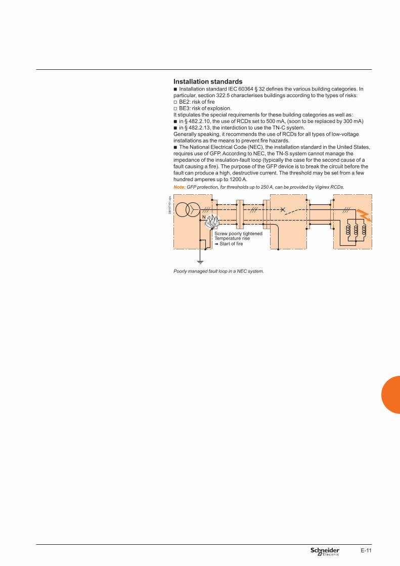
E-11
Installation standards b Installation standard IEC 60364 § 32 defines the various building categories. In
particular, section 322.5 characterises buildings according to the types of risks: v BE2: risk of fire v BE3: risk of explosion.
It stipulates the special requirements for these building categories as well as: b in § 482.2.10, the use of RCDs set to 500 mA, (soon to be replaced by 300 mA) b in § 482.2.13, the interdiction to use the TN-C system.
Generally speaking, it recommends the use of RCDs for all types of low-voltage installations as the means to prevent fire hazards.
b The National Electrical Code (NEC), the installation standard in the United States, requires use of GFP. According to NEC, the TN-S system cannot manage the impedance of the insulation-fault loop (typically the case for the second cause of a fault causing a fire). The purpose of the GFP device is to break the circuit before the fault can produce a high, destructive current. The threshold may be set from a few hundred amperes up to 1200 A.Note: GFP protection, for thresholds up to 250 A, can be provided by Vigirex RCDs.
DB
1071
01.e
ps
Poorly managed fault loop in a NEC system.
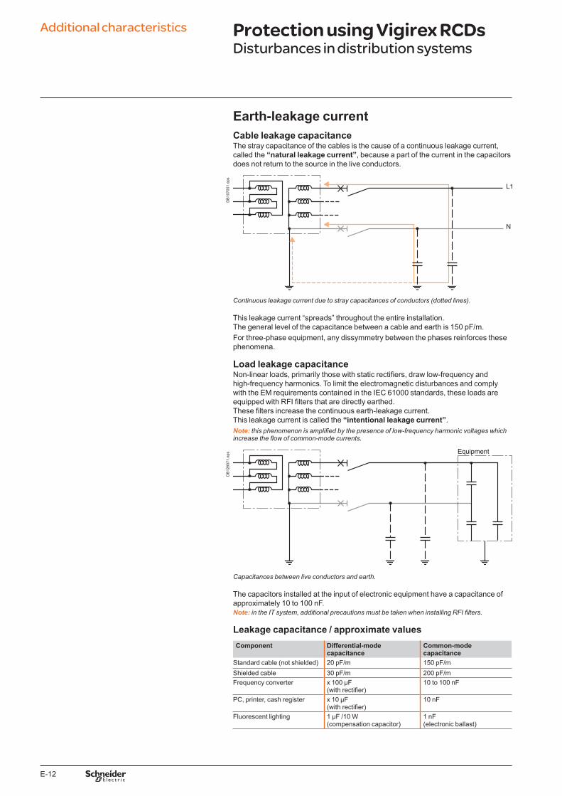
E-12
Earth-leakage currentCable leakage capacitanceThe stray capacitance of the cables is the cause of a continuous leakage current, called the “natural leakage current”, because a part of the current in the capacitors does not return to the source in the live conductors.
DB
1070
01.e
ps
Continuous leakage current due to stray capacitances of conductors (dotted lines).
This leakage current “spreads” throughout the entire installation.The general level of the capacitance between a cable and earth is 150 pF/m.For three-phase equipment, any dissymmetry between the phases reinforces these phenomena.
Load leakage capacitanceNon-linear loads, primarily those with static rectifiers, draw low-frequency and high-frequency harmonics. To limit the electromagnetic disturbances and comply with the EM requirements contained in the IEC 61000 standards, these loads are equipped with RFI filters that are directly earthed. These filters increase the continuous earth-leakage current. This leakage current is called the “intentional leakage current”.Note: this phenomenon is amplified by the presence of low-frequency harmonic voltages which increase the flow of common-mode currents.
DB
1260
71.e
ps
Capacitances between live conductors and earth.
The capacitors installed at the input of electronic equipment have a capacitance of approximately 10 to 100 nF.Note: in the IT system, additional precautions must be taken when installing RFI filters.
Leakage capacitance / approximate valuesComponent Differential-mode
capacitanceCommon-mode capacitance
Standard cable (not shielded) 20 pF/m 150 pF/mShielded cable 30 pF/m 200 pF/mFrequency converter x 100 µF
(with rectifier)10 to 100 nF
PC, printer, cash register x 10 µF (with rectifier)
10 nF
Fluorescent lighting 1 µF /10 W(compensation capacitor)
1 nF(electronic ballast)
Additional characteristics Protection using Vigirex RCDsDisturbances in distribution systems
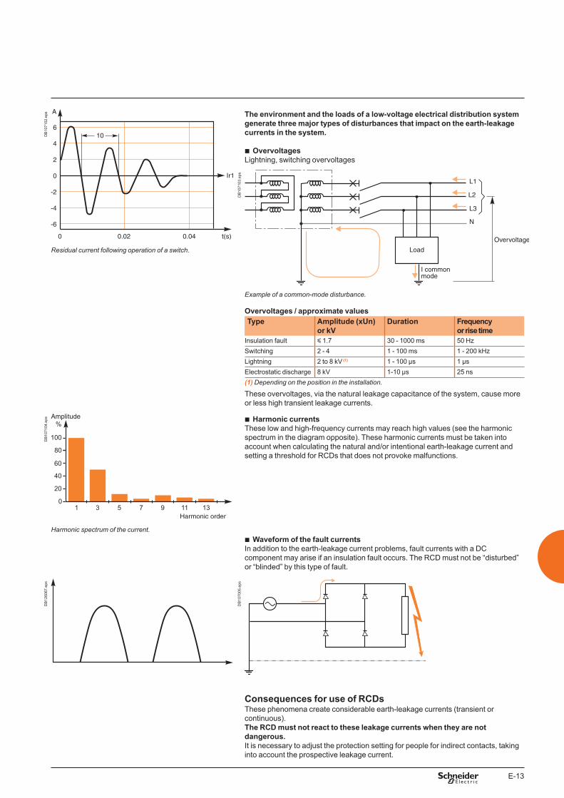
E-13
DB
1071
02.e
ps The environment and the loads of a low-voltage electrical distribution system generate three major types of disturbances that impact on the earth-leakage currents in the system.
b OvervoltagesLightning, switching overvoltages
DB
1071
03.e
ps
Residual current following operation of a switch.
Example of a common-mode disturbance.
Overvoltages / approximate valuesType Amplitude (xUn)
or kVDuration Frequency
or rise timeInsulation fault y 1.7 30 - 1000 ms 50 HzSwitching 2 - 4 1 - 100 ms 1 - 200 kHzLightning 2 to 8 kV (1) 1 - 100 µs 1 µsElectrostatic discharge 8 kV 1-10 µs 25 ns(1) Depending on the position in the installation.
These overvoltages, via the natural leakage capacitance of the system, cause more or less high transient leakage currents.
DB
1071
04.e
ps b Harmonic currentsThese low and high-frequency currents may reach high values (see the harmonic spectrum in the diagram opposite). These harmonic currents must be taken into account when calculating the natural and/or intentional earth-leakage current and setting a threshold for RCDs that does not provoke malfunctions.
Harmonic spectrum of the current. b Waveform of the fault currents
In addition to the earth-leakage current problems, fault currents with a DC component may arise if an insulation fault occurs. The RCD must not be “disturbed” or “blinded” by this type of fault.
DB
1260
87.e
ps
DB
1070
05.e
ps
Consequences for use of RCDsThese phenomena create considerable earth-leakage currents (transient or continuous). The RCD must not react to these leakage currents when they are not dangerous.It is necessary to adjust the protection setting for people for indirect contacts, taking into account the prospective leakage current.
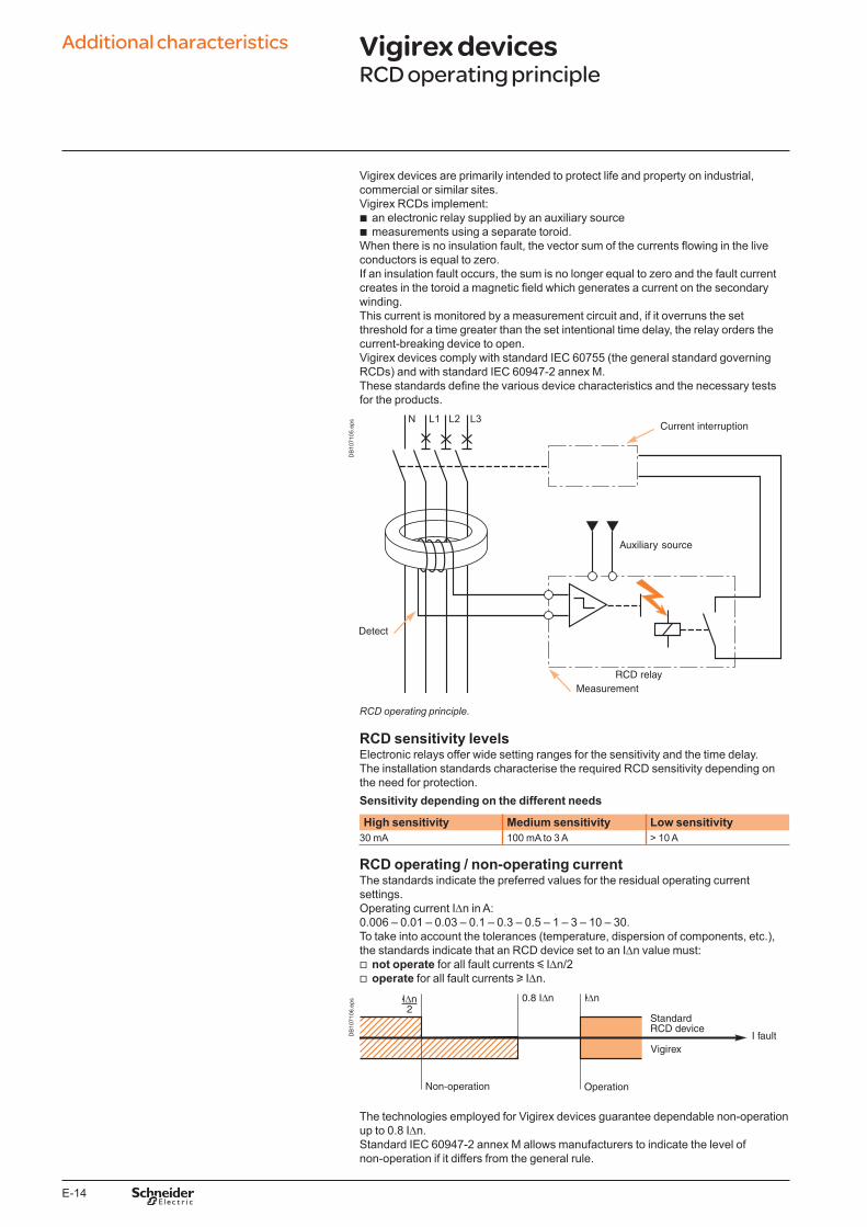
E-14
Vigirex devices are primarily intended to protect life and property on industrial, commercial or similar sites.Vigirex RCDs implement:
b an electronic relay supplied by an auxiliary source b measurements using a separate toroid.
When there is no insulation fault, the vector sum of the currents flowing in the live conductors is equal to zero.If an insulation fault occurs, the sum is no longer equal to zero and the fault current creates in the toroid a magnetic field which generates a current on the secondary winding. This current is monitored by a measurement circuit and, if it overruns the set threshold for a time greater than the set intentional time delay, the relay orders the current-breaking device to open.Vigirex devices comply with standard IEC 60755 (the general standard governing RCDs) and with standard IEC 60947-2 annex M. These standards define the various device characteristics and the necessary tests for the products.
DB
1071
05.e
ps
RCD operating principle.
RCD sensitivity levelsElectronic relays offer wide setting ranges for the sensitivity and the time delay.The installation standards characterise the required RCD sensitivity depending on the need for protection.Sensitivity depending on the different needs
High sensitivity Medium sensitivity Low sensitivity30 mA 100 mA to 3 A > 10 A
RCD operating / non-operating currentThe standards indicate the preferred values for the residual operating current settings.Operating current IDn in A:0.006 – 0.01 – 0.03 – 0.1 – 0.3 – 0.5 – 1 – 3 – 10 – 30.To take into account the tolerances (temperature, dispersion of components, etc.), the standards indicate that an RCD device set to an IDn value must:
v not operate for all fault currents y IDn/2 v operate for all fault currents u IDn.
DB
1071
06.e
ps
The technologies employed for Vigirex devices guarantee dependable non-operation up to 0.8 IDn.Standard IEC 60947-2 annex M allows manufacturers to indicate the level of non-operation if it differs from the general rule.
Additional characteristics Vigirex devicesRCD operating principle
E-15
Measurement of residual currentsThe main difficulties for industrial RCDs lie in ensuring high-quality measurements.
b The measurement of fault currents in the presence of linear loads is not difficult: v the frequency of the fault current is 50/60 Hz v leakage currents are generally low b However, the measurement of fault currents in the presence of non-linear loads
requires RCDs capable of: v discriminating between the fault current and leakage currents v not being “blinded” by the DC components.
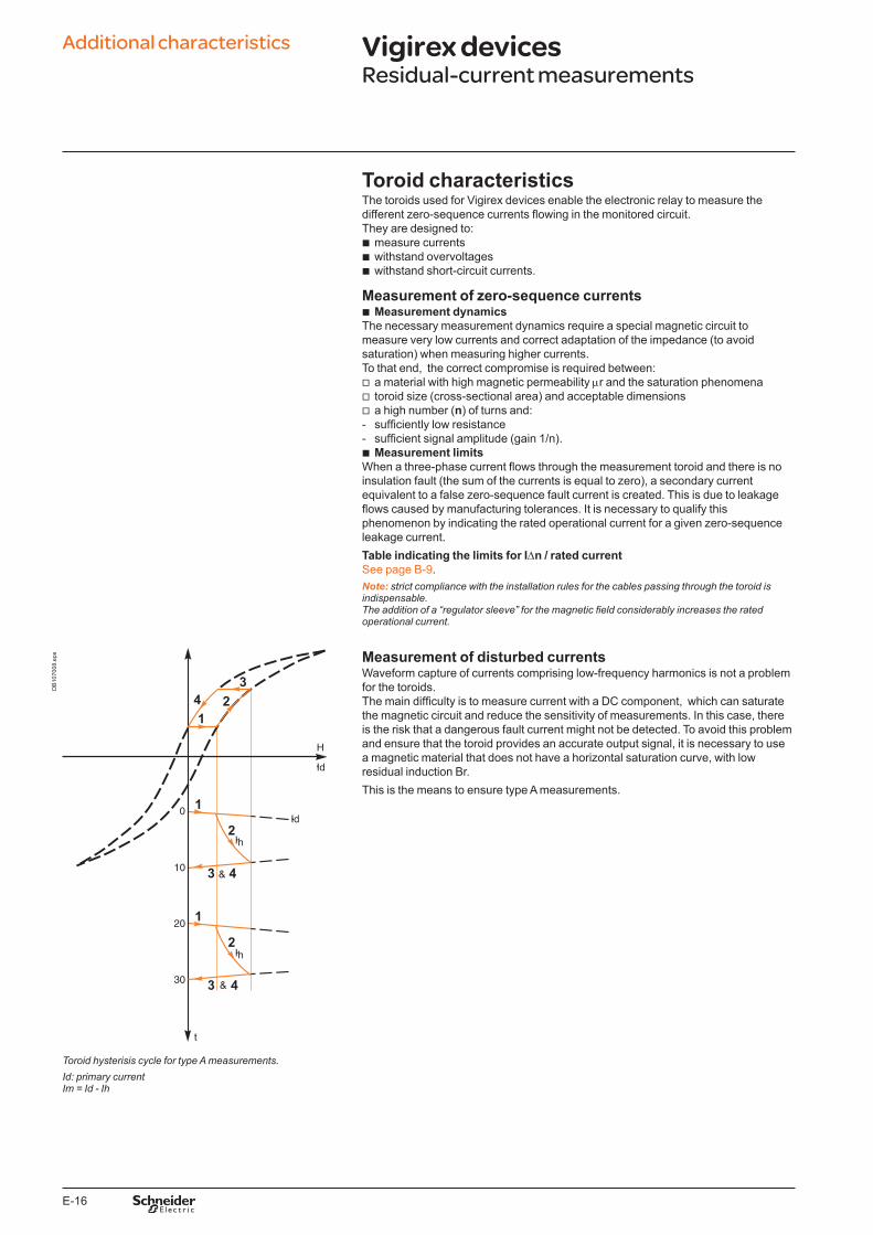
E-16
Toroid characteristicsThe toroids used for Vigirex devices enable the electronic relay to measure the different zero-sequence currents flowing in the monitored circuit. They are designed to:
b measure currents b withstand overvoltages b withstand short-circuit currents.
Measurement of zero-sequence currents b Measurement dynamics
The necessary measurement dynamics require a special magnetic circuit to measure very low currents and correct adaptation of the impedance (to avoid saturation) when measuring higher currents.To that end, the correct compromise is required between:
v a material with high magnetic permeability mr and the saturation phenomena v toroid size (cross-sectional area) and acceptable dimensions v a high number (n) of turns and:
- sufficiently low resistance - sufficient signal amplitude (gain 1/n). b Measurement limits
When a three-phase current flows through the measurement toroid and there is no insulation fault (the sum of the currents is equal to zero), a secondary current equivalent to a false zero-sequence fault current is created. This is due to leakage flows caused by manufacturing tolerances. It is necessary to qualify this phenomenon by indicating the rated operational current for a given zero-sequence leakage current. Table indicating the limits for IDn / rated currentSee page B-9.Note: strict compliance with the installation rules for the cables passing through the toroid is indispensable. The addition of a “regulator sleeve” for the magnetic field considerably increases the rated operational current.
DB
1070
08.e
ps Measurement of disturbed currentsWaveform capture of currents comprising low-frequency harmonics is not a problem for the toroids. The main difficulty is to measure current with a DC component, which can saturate the magnetic circuit and reduce the sensitivity of measurements. In this case, there is the risk that a dangerous fault current might not be detected. To avoid this problem and ensure that the toroid provides an accurate output signal, it is necessary to use a magnetic material that does not have a horizontal saturation curve, with low residual induction Br.This is the means to ensure type A measurements.
Toroid hysterisis cycle for type A measurements.Id: primary currentIm = Id - Ih
Additional characteristics Vigirex devicesResidual-current measurements
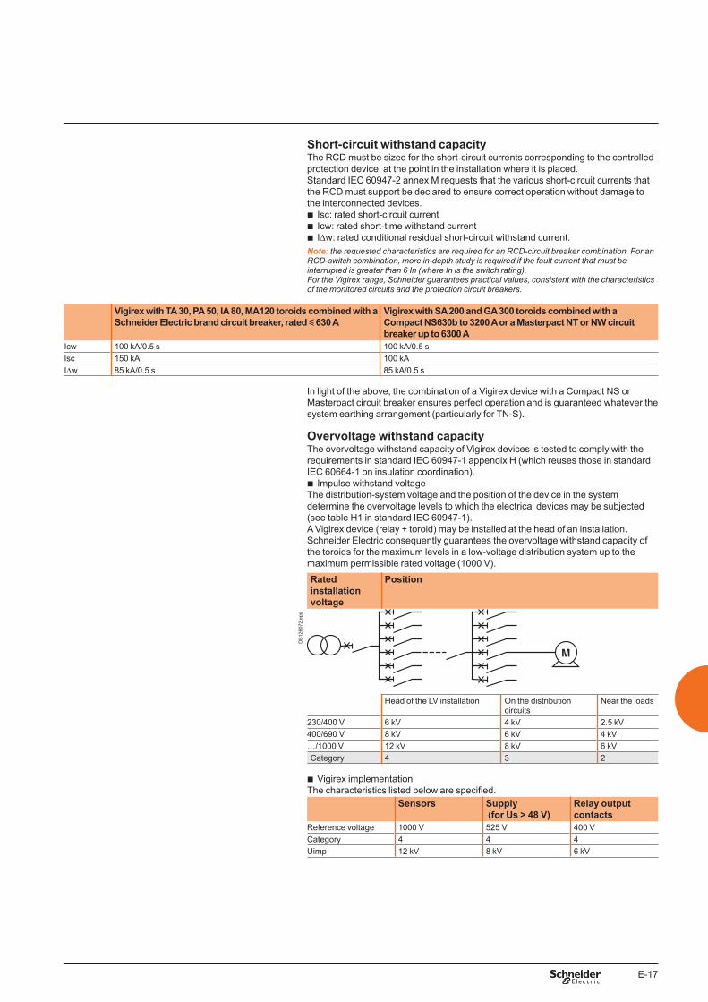
E-17
Short-circuit withstand capacityThe RCD must be sized for the short-circuit currents corresponding to the controlled protection device, at the point in the installation where it is placed. Standard IEC 60947-2 annex M requests that the various short-circuit currents that the RCD must support be declared to ensure correct operation without damage to the interconnected devices.
b Isc: rated short-circuit current b Icw: rated short-time withstand current b IDw: rated conditional residual short-circuit withstand current.
Note: the requested characteristics are required for an RCD-circuit breaker combination. For an RCD-switch combination, more in-depth study is required if the fault current that must be interrupted is greater than � In (where In is the switch rating). For the Vigirex range, Schneider guarantees practical values, consistent with the characteristics of the monitored circuits and the protection circuit breakers.
Vigirex with TA 30, PA 50, IA 80, MA120 toroids combined with a Schneider Electric brand circuit breaker, rated y 630 A
Vigirex with SA 200 and GA 300 toroids combined with a Compact NS630b to 3200 A or a Masterpact NT or NW circuit breaker up to 6300 A
Icw 100 kA/0.5 s 100 kA/0.5 sIsc 150 kA 100 kAIDw 85 kA/0.5 s 85 kA/0.5 s
In light of the above, the combination of a Vigirex device with a Compact NS or Masterpact circuit breaker ensures perfect operation and is guaranteed whatever the system earthing arrangement (particularly for TN-S).
Overvoltage withstand capacityThe overvoltage withstand capacity of Vigirex devices is tested to comply with the requirements in standard IEC 60947-1 appendix H (which reuses those in standard IEC 60664-1 on insulation coordination).
b Impulse withstand voltageThe distribution-system voltage and the position of the device in the system determine the overvoltage levels to which the electrical devices may be subjected (see table H1 in standard IEC 60947-1).A Vigirex device (relay + toroid) may be installed at the head of an installation. Schneider Electric consequently guarantees the overvoltage withstand capacity of the toroids for the maximum levels in a low-voltage distribution system up to the maximum permissible rated voltage (1000 V).
Rated installation voltage
Position
DB
1260
72.e
ps
Head of the LV installation On the distribution circuits
Near the loads
230/400 V 6 kV 4 kV 2.5 kV400/690 V 8 kV 6 kV 4 kV…/1000 V 12 kV 8 kV 6 kVCategory 4 3 2
b Vigirex implementationThe characteristics listed below are specified.
Sensors Supply (for Us > 48 V)
Relay output contacts
Reference voltage 1000 V 525 V 400 VCategory 4 4 4Uimp 12 kV 8 kV 6 kV
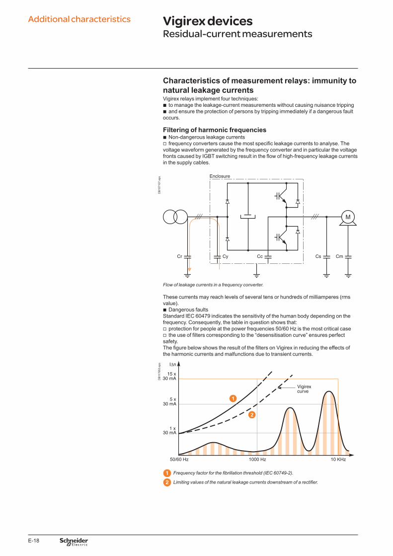
E-18
Characteristics of measurement relays: immunity to natural leakage currentsVigirex relays implement four techniques:
b to manage the leakage-current measurements without causing nuisance tripping b and ensure the protection of persons by tripping immediately if a dangerous fault
occurs.
Filtering of harmonic frequencies b Non-dangerous leakage currents v frequency converters cause the most specific leakage currents to analyse. The
voltage waveform generated by the frequency converter and in particular the voltage fronts caused by IGBT switching result in the flow of high-frequency leakage currents in the supply cables.
DB
1071
07.e
ps
Flow of leakage currents in a frequency converter.
These currents may reach levels of several tens or hundreds of milliamperes (rms value).
b Dangerous faultsStandard IEC 60479 indicates the sensitivity of the human body depending on the frequency. Consequently, the table in question shows that:
v protection for people at the power frequencies 50/60 Hz is the most critical case v the use of filters corresponding to the “desensitisation curve” ensures perfect
safety.The figure below shows the result of the filters on Vigirex in reducing the effects of the harmonic currents and malfunctions due to transient currents.
DB
1178
53.e
ps
Frequency factor for the fibrillation threshold (IEC 60749-2).
Limiting values of the natural leakage currents downstream of a rectifier.
Additional characteristics Vigirex devicesResidual-current measurements
E-19
Rms measurementsVigirex devices carry out rms measurements on the zero-sequence currents. This is the means to:
b accurately measure the harmonic currents and avoid nuisance tripping due to non-dangerous currents with high crest factors
b correctly calibrate the energies of the fault currents because, for both fire hazards and the protection of property, it is the energy of the fault current that must be taken into account.
DB
1071
09.e
ps Curve IDn / non-delayed relay timesProtection for people requires the use of non-delay type relays. These relays must comply with standards to ensure safety. Standards IEC 60947-2 annex M and IEC 60755 indicate the preferred values for the operating-current setting.They stipulate the maximum break time depending on the residual fault current.See table B in B.4.2.4.1 in standard IEC 60947-2 annex M.
If = IDn 2 IDn 5 IDn 10 IDnTime Tps 0.3 s 0.15 s 0.04 s 0.04 sKey: Time Tps: total time required to break the current (including the time for the associated protection device to open) If: leakage current IDn: residual operating current setting
For devices set to 30 mA, 5 IDn can be replaced by 0.25 A, in which case 10 IDn is replaced by 0.5 A. Vigirex uses this type of response curve to manage the false fault currents caused by switching in of loads (transformers, motors).Standardised RCD response curve as per the table.
Leakage-current curve for switching in of a load with leakage capacitance.
Schneider Electric guarantees all the above break times for a Vigirex combined with its circuit breakers rated up to y 630 A, particularly when set to 30 mA.
Guaranteed non-operation up to 0.8 IDnThis function equipping Vigirex relays significantly increases (from 0.5 IDn to 0.8 IDn) the immunity of relays to continuous leakage currents, both natural and intentional.

E-20
Characteristics of measurement relays: measurement of disturbed currents containing DC componentsIf an insulation fault occurs downstream of a rectifier, a current containing a DC component is created. The protection devices must remain operational in spite of the DC component.
DB
1071
10.e
ps
Fault on the DC bus of a converter.
Classification depending on the residual current to be monitoredThe standards define three classifications of residual-current protection depending on the current that must be analysed:
b AC type: for sinusoidal AC current. b A type: for AC current with a DC component. These devices are suitable for the
detection of rectified single-phase currents. b B type: for DC current. These devices are suitable for all types of current and are
required, in particular, for rectified three-phase currents.
DB
1260
73.e
ps
Waveforms of the test currents for A-type RCDs.
Additional characteristics Vigirex devicesResidual-current measurements

E-21
Selection of industrial RCDsSchneider Electric has carried out large numbers of tests to characterise user needs. A complete analysis of the phenomena involved is available in Cahier Technique document 204.The table below (copied from chapter 6 of CT document 204) sums up the information: it indicates the type of RCD to be used depending on the system earthing arrangement, the equipment to be monitored and the type of protection required.
Summary tableType of circuit Application Diagram Suitable type of RCD
Diode-based single-phase rectifier - frequency converters, variable-speed drives- supplies for DC circuits
DB
1260
74.e
ps A
SCR-based single-phase rectifier - variable-speed drives- battery chargers
DB
1260
75.e
ps A
Regulation devices - light dimmer- heating regulator
DB
1260
76.e
ps AC
AC/AC converter with single-phase supply
- variable-speed drives
DB
1260
77.e
ps A
AC/AC converter with three-phase supply
- variable-speed drives- welding machines
DB
1260
78.e
ps BA (if no risk of fault on the DC bus)
Protection Against indirect contact Against direct contactSupply Three-phase Single-phase Three-phase Single-phaseEquipment and installation characteristics
No double insulation of DC bus
With double insulation of DC bus
If further protection is required, if other protection systems against contact fail or if users are careless (see the installation standards).
SLT: TT or IT with exposed conductive parts not interconnected
B type, low sensitivity (u 300 mA)
A type, low sensitivity (u 300 mA)
A type, low sensitivity (u 300 mA)
A type (30 mA) or B type (30 mA) if the braking resistance is accessible
A type30 mA
SLT: TN-S A type, low sensitivity (u 300 mA) (1)
SLT: IT(1) The insulation fault is equivalent to a short-circuit. Tripping should normally be ensured by the short-circuit protection, but use of an RCD is recommended if there is any risk the overcurrent protection will not operate.
E-22
DB
4149
50.e
ps Characteristics of the relay / toroid combination: measurement integrityThe integrity of measurements depends on the capacity of the RCD to handle the various disturbances on the distribution system. The generic standard for EMC is IEC 61000-6-2 which defines the minimum immunity level. The test standards in the IEC 61000 series define the various requirement levels. Standard IEC 60947-2 annex M determines the required level for RCDs with separate toroids. Schneider has established for the Vigirex RCDs its own requirements that are similar or more demanding than those in the standard. The table below lists the required tests.
Vigirex wired for optimum safety.
Description of phenomena Test standard Standardised tests as per IEC 60947-2 annex M
Vigirex tests
Title CodeDischarges, due to the accumulation of static electricity, can lead to malfunctions and destruction.
Electrostatic-discharge immunity test
IEC 61000-4-2 8 kV contact8 kV in air
8 kV contact15 kV in air
Radiated EM fields (radio-telephones, transmitters) can disturb operation of devices.
Radiated (radio-frequency) EM field immunity test
IEC 61000-4-3 10 V /m80 to 1000 MHzmodulated at 1 kHz
12 V /m80 to 1000 MHzmodulated at 1 kHz
Switching of LV devices (contactors, contact bouncing, breaking of inductive loads, etc.) may cause malfunctions and destruction.
Electrical fast transients/bursts immunity test
IEC 61000-4-4 4 kV on supply2 kV on I/O5 kHz fast burst/transient lasting 15 ms every 300 ms
4 kV on supply2 kV on I/O5 kHz fast burst/transient lasting 15 ms every 300 ms
Atmospheric overvoltages, switching of MV devices may cause malfunctions and destruction.
Surge immunity test IEC 61000-4-5 - On supply > 100 V AC4 kV between line and earth4 kV between lines- On supply < 100 V AC2 kV between line and earth1 kV between lines- On DC supply0.5 kV between line and earth0.5 kV between lines- On input/output (I/O)2 kV between line and earth1 kV between lines1.2/50 µs wave, open circuit8 / 20 µs short-circuit
- On supply > 100 V AC4 kV between line and earth4 kV between lines- On supply < 100 V AC (1)
4 kV between line and earth4 kV between lines- On DC supply2 kV between line and earth1 kV between lines- On input/output (I/O)2 kV between line and earth1 kV between lines1.2/50 µs wave, open circuit8 / 20 µs short-circuit
EM fields (radio-telephones, transmitters) can cause HF currents resulting in device malfunctions.
Immunity test for conducted disturbances induced by radio-frequency fields
IEC 61000-4-6 10 V 150 kHz to 80 MHzmodulated at 1 kHz
10 V 150 kHz to 80 MHzmodulated at 1 kHz
Faults on the distribution system may cause malfunctions.
Voltage-dip immunity test
IEC 61000-4-11 Specific RCD-device tests -
(1) V AC < 48 V, the Vigirex does not have a supply transformer.
Additional characteristics Vigirex devicesResidual-current measurements
E-23
Voltage-dip withstand capacityStandard IEC 60947-2 annex M defines precise criteria for the voltage-dip withstand capacity of RCDs that depend on the supply voltage. To guarantee safety, even if the auxiliary source fails, the RCD must operate correctly to 70 % of the rated auxiliary-source voltage.Vigirex devices comply with the standard.
b Operation under downgraded voltage conditions (see the characteristics on pages A-26 to A-35). Additional standard functions are built in to make the protection as dependable as possible:
v failsafe operation is possible, see relay wiring v a voltage LED provides a local indication that voltage is not present.
E-24
Continuity of service: RCD device discriminationDiscrimination is ensured between the RCDs by using time-delay type RCDs.Standardised characteristics of time-delay type RCDsThe standards governing RCDs define two categories for time-delay type RCDs.
b RCD with a time delay y 0.06 s These devices generally have a single, non-adjustable time delay. They are intended to ensure discrimination with non-time-delay type RCDs. The standards impose the following characteristics:
v non-operating time Time delay set for 2 IDn; must not exceed 0.06 s
v operating time (relay alone) Must be indicated by the manufacturer
v total time (relay plus breaking device) The manufacturer must indicate the associated device and guarantee maximum total times not exceeding those in the table below.
If = IDn 2 IDn 5 IDn 10 IDnTime Tps 0.5 s 0.2 s 0.15 s 0.15 sKey: Time Tps: total time required to break the current If: leakage current IDn: residual operating current setting.Note: if the threshold is set to < �0 mA, the relay must operate immediately.
I n (A)
t (s)
RH99MVigirex
DB
1259
80.e
ps When set to I, Vigirex relays comply with the requirements for these time-delay type RCDs.
b RCD with time delay > 0.06 sThese are primarily industrial time-delay type RCDs used to ensure several levels of discrimination.
v preferred non-operating times (in s) The standard proposes the following time delays: 0.1 – 0.2 – 0.3 – 0.4 – 0.5 – 1. The operating time must be indicated on the relay and guaranteed by the manufacturer.
v operating time (relay alone) Must be indicated and guaranteed by the manufacturer
v total time (relay plus breaking device)This time may be indicated by the manufacturer.
Vigirex RCDsVigirex RCDs offer a wide range of time delays and comply with the tests imposed by standard IEC 60947-2 annex M.
b Minimum non-operating time: indicated by the position of the delay setting dial on the front of the relay, as shown in the diagram opposite.
b Operating time / total time: indicated in the tables for device characteristics. For setting I (0.06 s) and the other time-delay settings, Schneider Electric guarantees the total times for Vigirex relays combined with Schneider Electric-brand breaking devices (switches, circuit breakers).
Implementing discriminationDiscrimination between upstream and downstream RCDs is necessarily of the current and time type.It is ensured by correctly adjusting:
b the operating-current settings b the total times.
The following general discrimination rules ensure correct operation: b in terms of the current, the setting for the upstream device must be double that of
the downstream device (in accordance with the standardised rules for the operating / non-operating currents)
b in terms of the time, the non-operating time (time delay) for the upstream device must be greater than the total time (the intentional RCD-device delay and the breaking time of the breaking device) for the downstream device.These two conditions are summed up here: upstream IDn u 2 x downstream IDnupstream non-operating time Dt u downstream total time Dt.
IDn (A): residual operating-current setting(the relay operates for a fault current u IDn).Schneider Electric guarantees non-operation for all fault currents < 0.8 IDn.Dt (s): minimum non-operating time.
Additional characteristics Vigirex devicesImplementation
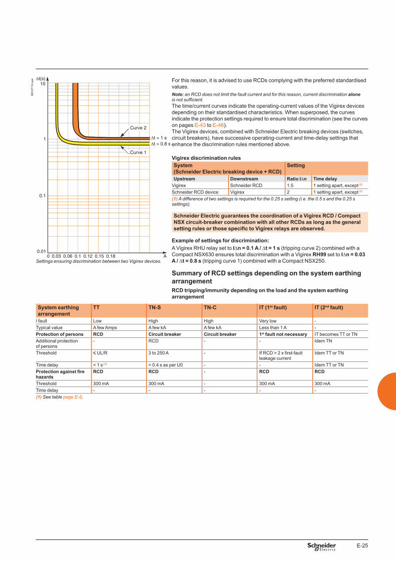
E-25
DB
1071
12.e
ps For this reason, it is advised to use RCDs complying with the preferred standardised values.Note: an RCD does not limit the fault current and for this reason, current discrimination alone is not sufficient.The time/current curves indicate the operating-current values of the Vigirex devices depending on their standardised characteristics. When superposed, the curves indicate the protection settings required to ensure total discrimination (see the curves on pages E-43 to E-46).The Vigirex devices, combined with Schneider Electric breaking devices (switches, circuit breakers), have successive operating-current and time-delay settings that enhance the discrimination rules mentioned above.
Vigirex discrimination rulesSystem (Schneider Electric breaking device + RCD)
Setting
Upstream Downstream Ratio IDn Time delayVigirex Schneider RCD 1.5 1 setting apart, except (1)
Schneider RCD device Vigirex 2 1 setting apart, except (1)
(1) A difference of two settings is required for the 0.25 s setting (i.e. the 0.5 s and the 0.25 s settings).
Schneider Electric guarantees the coordination of a Vigirex RCD / Compact NSX circuit-breaker combination with all other RCDs as long as the general setting rules or those specific to Vigirex relays are observed.
Example of settings for discrimination:A Vigirex RHU relay set to IDn = 0.1 A / Dt = 1 s (tripping curve 2) combined with a Compact NSX630 ensures total discrimination with a Vigirex RH99 set to IDn = 0.03 A / Dt = 0.8 s (tripping curve 1) combined with a Compact NSX250.
Summary of RCD settings depending on the system earthing arrangementRCD tripping/immunity depending on the load and the system earthing arrangement
Settings ensuring discrimination between two Vigirex devices.
System earthing arrangement
TT TN-S TN-C IT (1st fault) IT (2nd fault)
I fault Low High High Very low -Typical value A few Amps A few kA A few kA Less than 1 A -Protection of persons RCD Circuit breaker Circuit breaker 1st fault not necessary IT becomes TT or TNAdditional protection of persons
- RCD - - Idem TN
Threshold y UL/R 3 to 250 A - If RCD > 2 x first-fault leakage current
Idem TT or TN
Time delay < 1 s (1) < 0.4 s as per U0 - - Idem TT or TNProtection against fire hazards
RCD RCD - RCD RCD
Threshold 300 mA 300 mA - 300 mA 300 mATime delay - - - - -(1) See table page E-5.
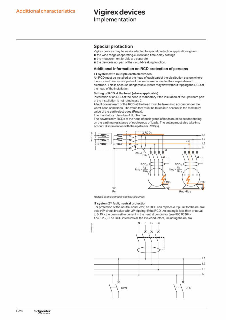
E-26
Special protectionVigirex devices may be easily adapted to special protection applications given:
b the wide range of operating-current and time-delay settings b the measurement toroids are separate b the device is not part of the circuit-breaking function.
Additional information on RCD protection of personsTT system with multiple earth electrodesAn RCD must be installed at the head of each part of the distribution system where the exposed conductive parts of the loads are connected to a separate earth electrode. This is because dangerous currents may flow without tripping the RCD at the head of the installation.Setting of RCD at the head (where applicable)Installation of an RCD at the head is mandatory if the insulation of the upstream part of the installation is not rated class 2.A fault downstream of the RCD at the head must be taken into account under the worst-case conditions. The value that must be taken into account is the maximum value of the earth electrodes (Rmax).The mandatory rule is IDn y UL / Ru max.The downstream RCDs at the head of each group of loads must be set depending on the earthing resistance of each group of loads. The setting must also take into account discrimination with the upstream RCD(s).
DB
1071
13.e
ps
Multiple earth electrodes and flow of current.
IT system 2nd fault, neutral protectionFor protection of the neutral conductor, an RCD can replace a trip unit for the neutral pole (4P circuit breaker with 3P tripping) if the RCD IDn setting is less than or equal to 0.15 x the permissible current in the neutral conductor (see IEC 60364 - 474.3.2.2). The RCD interrupts all the live conductors, including the neutral.
DB
1260
80.e
ps
Additional characteristics Vigirex devicesImplementation
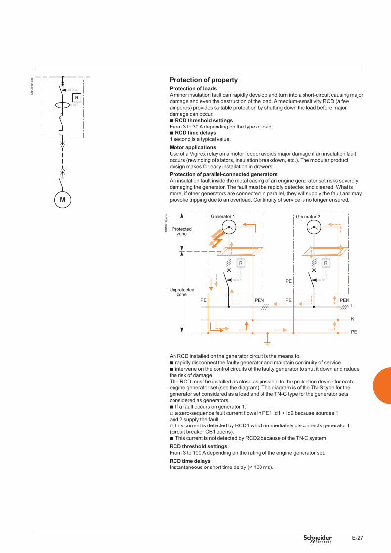
E-27
DB
1260
81.e
ps Protection of propertyProtection of loadsA minor insulation fault can rapidly develop and turn into a short-circuit causing major damage and even the destruction of the load. A medium-sensitivity RCD (a few amperes) provides suitable protection by shutting down the load before major damage can occur.
b RCD threshold settingsFrom 3 to 30 A depending on the type of load
b RCD time delays1 second is a typical value.Motor applicationsUse of a Vigirex relay on a motor feeder avoids major damage if an insulation fault occurs (rewinding of stators, insulation breakdown, etc.). The modular product design makes for easy installation in drawers.Protection of parallel-connected generatorsAn insulation fault inside the metal casing of an engine generator set risks severely damaging the generator. The fault must be rapidly detected and cleared. What is more, if other generators are connected in parallel, they will supply the fault and may provoke tripping due to an overload. Continuity of service is no longer ensured.
DB
1071
14.e
ps
An RCD installed on the generator circuit is the means to: b rapidly disconnect the faulty generator and maintain continuity of service b intervene on the control circuits of the faulty generator to shut it down and reduce
the risk of damage.The RCD must be installed as close as possible to the protection device for each engine generator set (see the diagram). The diagram is of the TN-S type for the generator set considered as a load and of the TN-C type for the generator sets considered as generators.
b If a fault occurs on generator 1: v a zero-sequence fault current flows in PE1 Id1 + Id2 because sources 1
and 2 supply the fault. v this current is detected by RCD1 which immediately disconnects generator 1
(circuit breaker CB1 opens). b This current is not detected by RCD2 because of the TN-C system.
RCD threshold settings From 3 to 100 A depending on the rating of the engine generator set.RCD time delaysInstantaneous or short time delay (< 100 ms).
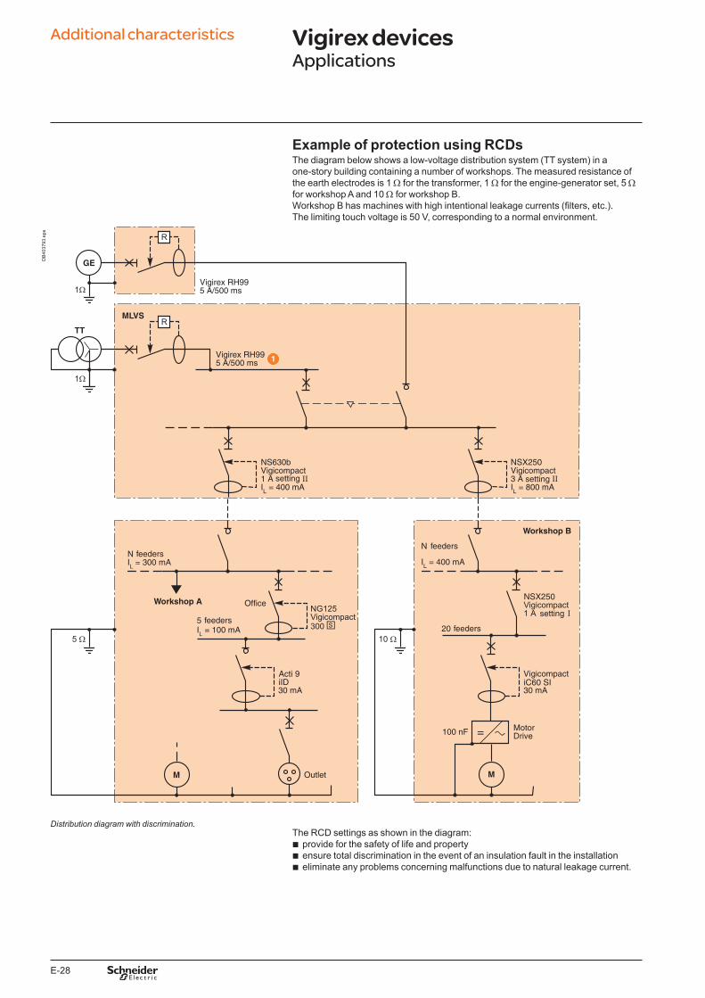
E-28
Example of protection using RCDsThe diagram below shows a low-voltage distribution system (TT system) in a one-story building containing a number of workshops. The measured resistance of the earth electrodes is 1 W for the transformer, 1 W for the engine-generator set, 5 W for workshop A and 10 W for workshop B.Workshop B has machines with high intentional leakage currents (filters, etc.). The limiting touch voltage is 50 V, corresponding to a normal environment.
NSX250
NSX250
Acti 9iID iC60 SI
DB
4037
93.e
ps
Distribution diagram with discrimination.The RCD settings as shown in the diagram:
b provide for the safety of life and property b ensure total discrimination in the event of an insulation fault in the installation b eliminate any problems concerning malfunctions due to natural leakage current.
Additional characteristics Vigirex devicesApplications
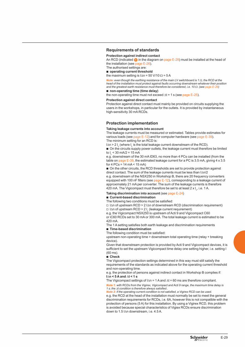
E-29
Requirements of standardsProtection against indirect contactAn RCD (indicated in the diagram on page E-28) must be installed at the head of the installation (see page E-26). The authorised settings are:
b operating current thresholdthe maximum setting is IDn = 50 V/10 W = 5 ANote: even though the earthing resistance of the main LV switchboard is 1 W, the RCD at the head of the installation must protect against faults occurring downstream whatever their position and the greatest earth resistance must therefore be considered, i.e. 10 W. (see page E-2�)
b non-operating time (time delay)the non-operating time must not exceed Dt = 1 s (see page E-25).Protection against direct contactProtection against direct contact must mainly be provided on circuits supplying the users in the workshops, in particular for the outlets. It is provided by instantaneous high-sensitivity 30 mA RCDs.
Protection implementationTaking leakage currents into accountThe leakage currents must be measured or estimated. Tables provide estimates for various loads (see page E-12) and for computer hardware (see page E-39).The minimum setting for an RCD is:IDn > 2 IL (where IL is the total leakage current downstream of the RCD).
b On the circuits supply power outlets, the leakage current must therefore be limited to IL < 30 mA/2 = 15 mAe.g. downstream of the 30 mA ID63, no more than 4 PCs can be installed (from the table on page E-39, the estimated leakage current for a PC is 3.5 mA, giving 4 x 3.5 for 4 PCs = 14 mA < 15 mA)
b On the other circuits, the RCD thresholds are set to provide protection against direct contact. The sum of the leakage currents must be less than IDn/2e.g. downstream of the NSX250 in Workshop B, there are 20 frequency converters equipped with 100 nF filters (see page E-12), corresponding to a leakage current of approximately 21 mA per converter. The sum of the leakage currents is therefore 420 mA. The Vigicompact must therefore be set to at least 2 x IL, i.e. 1 A.Taking discrimination into account (see page E-24)
b Current-based discriminationThe following two conditions must be satisfied:
v IDn of upstream RCD > 2 IDn of downstream RCD (discrimination requirement) v IDn of upstream RCD > 2 IL (leakage current requirement)
e.g. the Vigicompact NSX250 is upstream of Acti 9 and Vigicompact C60 or iC60 RCDs set to 30 mA or 300 mA. The total leakage current is estimated to be 420 mA. The 1 A setting satisfies both earth leakage and discrimination requirements
b Time-based discrimination The following condition must be satisfied:upstream non-operating time > downstream total operating time (relay + breaking device).Given that downstream protection is provided by Acti 9 and Vigicompact devices, it is sufficient to set the upstream Vigicompact time delay one setting higher, i.e. setting I (60 ms).
b CheckThe Vigicompact protection settings determined in this way must still satisfy the requirements of the standards as indicated above for the operating current threshold and non-operating time.e.g. the protection of persons against indirect contact in Workshop B complies if:IDn < 5 A and Dt < 1 s The Vigicompact settings of IDn = 1 A and Dt = 60 ms are therefore compliant.Note 1: with RCDs from the Vigirex, Vigicompact and Acti 9 range, the maximum time delay is 1 s; the Dt condition is therefore always satisfied..Note 2: if the operating current condition is not satisfied, a Vigirex RCD can be used. e.g. the RCD at the head of the installation must normally be set to meet the general discrimination requirements for RCDs, i.e. 6A, however this is not compatible with the protection of persons (5 A) for this installation. By using a Vigirex RCD, this problem is avoided because special characteristics of Vigiex RCDs ensure discrimination down to 1.5 IDn downstream, i.e. 4.5 A.
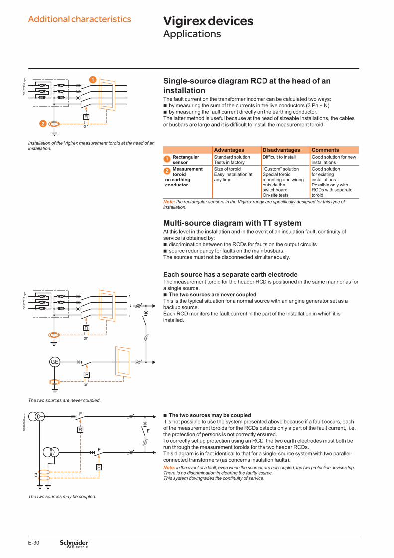
E-30
DB
1071
16.e
ps Single-source diagram RCD at the head of an installationThe fault current on the transformer incomer can be calculated two ways:
b by measuring the sum of the currents in the live conductors (3 Ph + N) b by measuring the fault current directly on the earthing conductor.
The latter method is useful because at the head of sizeable installations, the cables or busbars are large and it is difficult to install the measurement toroid.
Installation of the Vigirex measurement toroid at the head of an installation. Advantages Disadvantages Comments
Rectangular sensor
Standard solutionTests in factory
Difficult to install Good solution for new installations
Measurement toroid
on earthing conductor
Size of toroidEasy installation at any time
“Custom” solutionSpecial toroid mounting and wiring outside the switchboardOn-site tests
Good solution for existing installationsPossible only with RCDs with separate toroid
Note: the rectangular sensors in the Vigirex range are specifically designed for this type of installation.
Multi-source diagram with TT systemAt this level in the installation and in the event of an insulation fault, continuity of service is obtained by:
b discrimination between the RCDs for faults on the output circuits b source redundancy for faults on the main busbars.
The sources must not be disconnected simultaneously.
Each source has a separate earth electrodeThe measurement toroid for the header RCD is positioned in the same manner as for a single source.
b The two sources are never coupledThis is the typical situation for a normal source with an engine generator set as a backup source. Each RCD monitors the fault current in the part of the installation in which it is installed.
DB
1071
17.e
ps
The two sources are never coupled.
DB
1070
20.e
ps b The two sources may be coupledIt is not possible to use the system presented above because if a fault occurs, each of the measurement toroids for the RCDs detects only a part of the fault current, i.e. the protection of persons is not correctly ensured. To correctly set up protection using an RCD, the two earth electrodes must both be run through the measurement toroids for the two header RCDs. This diagram is in fact identical to that for a single-source system with two parallel-connected transformers (as concerns insulation faults).Note: in the event of a fault, even when the sources are not coupled, the two protection devices trip. There is no discrimination in clearing the faulty source. This system downgrades the continuity of service.
The two sources may be coupled.
Additional characteristics Vigirex devicesApplications
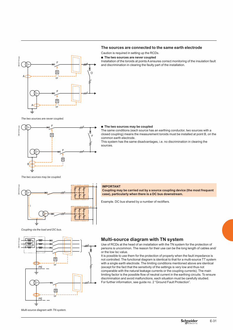
E-31
The sources are connected to the same earth electrodeCaution is required in setting up the RCDs.
DB
1071
18.e
ps b The two sources are never coupledInstallation of the toroids at points A ensures correct monitoring of the insulation fault and discrimination in clearing the faulty part of the installation.
The two sources are never coupled.
DB
1070
22.e
ps b The two sources may be coupled The same conditions (each source has an earthing conductor, two sources with a closed coupling) means the measurement toroids must be installed at point B, on the common earth electrode.This system has the same disadvantages, i.e. no discrimination in clearing the sources.
The two sources may be coupled.
DB
1070
23.e
ps IMPORTANT Coupling may be carried out by a source coupling device (the most frequent case), particularly when there is a DC bus downstream.
Example. DC bus shared by a number of rectifiers.
Coupling via the load and DC bus.
DB
1071
19.e
ps Multi-source diagram with TN systemUse of RCDs at the head of an installation with the TN system for the protection of persons is uncommon. The reason for their use can be the long length of cables and/or the low Isc value. It is possible to use them for the protection of property when the fault impedance is not controlled. The functional diagram is identical to that for a multi-source TT system with a single earth electrode. The limiting conditions mentioned above are identical (except for the fact that the sensitivity of the settings is very low and thus not comparable with the natural leakage currents or the coupling currents). The main limiting factor is the possible flow of neutral current in the earthing circuits. To ensure discrimination and avoid malfunctions, each situation must be carefully studied. For further information, see guide no. 2 “Ground Fault Protection”.
Multi-source diagram with TN system.
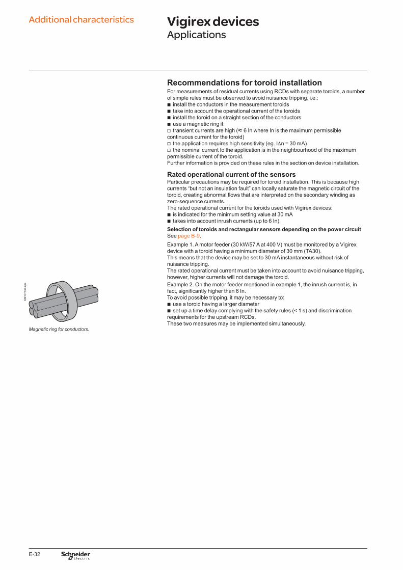
E-32
Recommendations for toroid installationFor measurements of residual currents using RCDs with separate toroids, a number of simple rules must be observed to avoid nuisance tripping, i.e.:
b install the conductors in the measurement toroids b take into account the operational current of the toroids b install the toroid on a straight section of the conductors b use a magnetic ring if: v transient currents are high (≈ 6 In where In is the maximum permissible
continuous current for the toroid) v the application requires high sensitivity (eg. IDn = 30 mA) v the nominal current fo the application is in the neighbourhood of the maximum
permissible current of the toroid.Further information is provided on these rules in the section on device installation.
Rated operational current of the sensorsParticular precautions may be required for toroid installation. This is because high currents “but not an insulation fault” can locally saturate the magnetic circuit of the toroid, creating abnormal flows that are interpreted on the secondary winding as zero-sequence currents.The rated operational current for the toroids used with Vigirex devices:
b is indicated for the minimum setting value at 30 mA b takes into account inrush currents (up to 6 In).
Selection of toroids and rectangular sensors depending on the power circuitSee page B-9.Example 1. A motor feeder (30 kW/57 A at 400 V) must be monitored by a Vigirex device with a toroid having a minimum diameter of 30 mm (TA30).This means that the device may be set to 30 mA instantaneous without risk of nuisance tripping.The rated operational current must be taken into account to avoid nuisance tripping, however, higher currents will not damage the toroid.
DB
1074
33.e
ps Example 2. On the motor feeder mentioned in example 1, the inrush current is, in fact, significantly higher than 6 In.To avoid possible tripping, it may be necessary to:
b use a toroid having a larger diameter b set up a time delay complying with the safety rules (< 1 s) and discrimination
requirements for the upstream RCDs.These two measures may be implemented simultaneously.
Magnetic ring for conductors.
Additional characteristics Vigirex devicesApplications
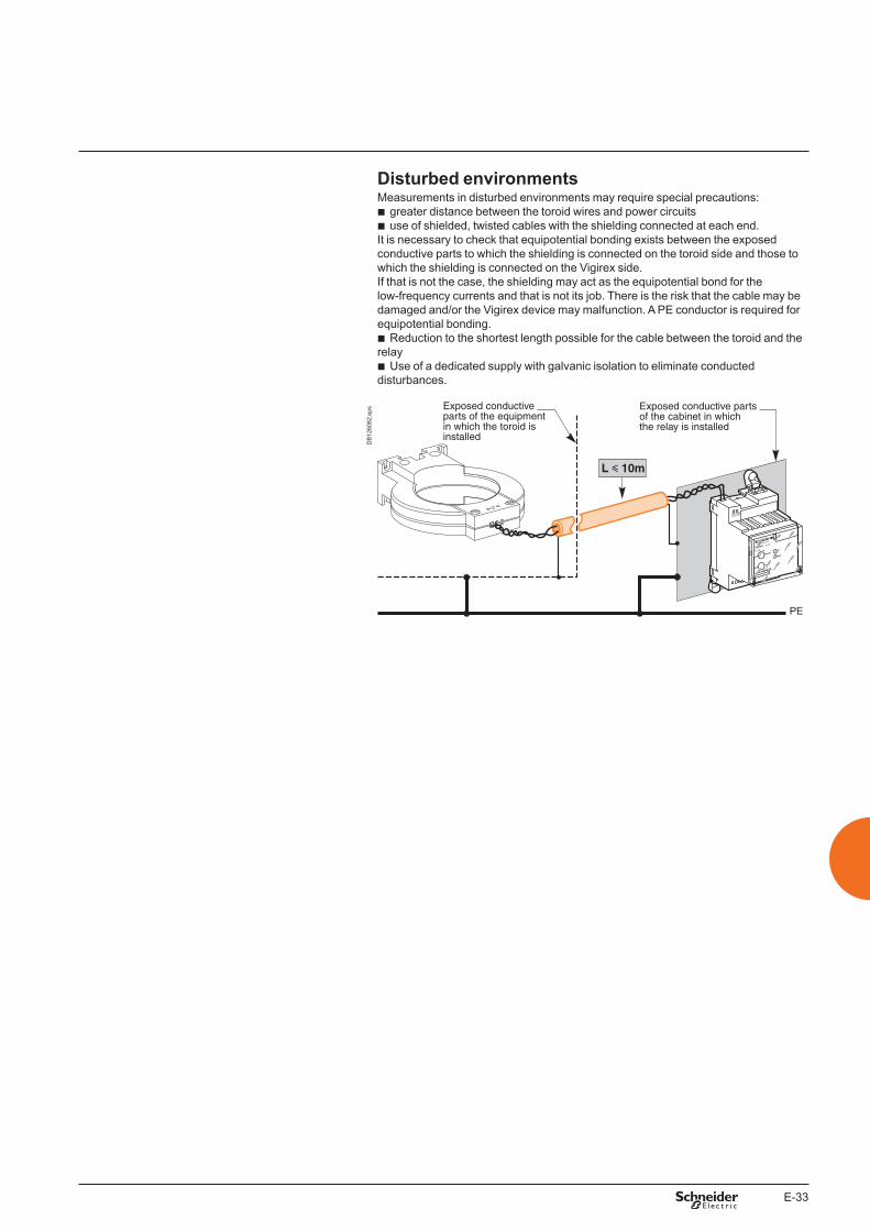
E-33
Disturbed environmentsMeasurements in disturbed environments may require special precautions:
b greater distance between the toroid wires and power circuits b use of shielded, twisted cables with the shielding connected at each end.
It is necessary to check that equipotential bonding exists between the exposed conductive parts to which the shielding is connected on the toroid side and those to which the shielding is connected on the Vigirex side. If that is not the case, the shielding may act as the equipotential bond for the low-frequency currents and that is not its job. There is the risk that the cable may be damaged and/or the Vigirex device may malfunction. A PE conductor is required for equipotential bonding.
b Reduction to the shortest length possible for the cable between the toroid and the relay
b Use of a dedicated supply with galvanic isolation to eliminate conducted disturbances.
Vigirex RH99M
DB
1260
82.e
ps
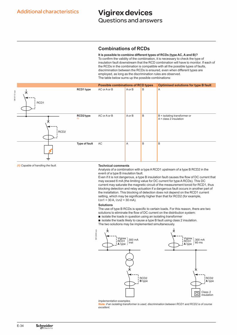
E-34
Additional characteristics Vigirex devicesQuestions and answers
DB
1071
21.e
ps
Combinations of RCDsIt is possible to combine different types of RCDs (type AC, A and B)? To confirm the validity of the combination, it is necessary to check the type of insulation fault downstream that the RCD combination will have to monitor. If each of the RCDs in the combination is compatible with all the possible types of faults, discrimination between the RCDs is ensured, even when different types are employed, as long as the discrimination rules are observed.The table below sums up the possible combinations:
Possible combinations of RCD types Optimised solutions for type B faultRCD1 type AC or A or B A or B B A
RCD2 type(1)
AC or A or B A or B B B + isolating transformer orA + class 2 insulation
Type of fault AC A B B
(1) Capable of handling the fault. Technical commentsAnalysis of a combination with a type A RCD1 upstream of a type B RCD2 in the event of a type B insulation fault.Even if it is not dangerous, a type B insulation fault causes the flow of DC current that may exceed 6 mA (the limiting value for DC current for type A RCDs). This DC current may saturate the magnetic circuit of the measurement toroid for RCD1, thus blocking detection and relay actuation if a dangerous fault occurs in another part of the installation. This blocking of detection does not depend on the RCD1 current setting, which may be significantly higher than that for RCD2 (for example, IDn1 = 30 A, IDn2 = 30 mA). SolutionsThe use of type B RCDs is specific to certain loads. For this reason, there are two solutions to eliminate the flow of DC current on the distribution system:
b isolate the loads in question using an isolating transformer b isolate the loads likely to cause a type B fault using class 2 insulation.
The two solutions may be implemented simultaneously.
DB
1260
83.e
ps
Implementation examples.Note: if an isolating transformer is used, discrimination between RCD1 and RCD2 is of course excellent.
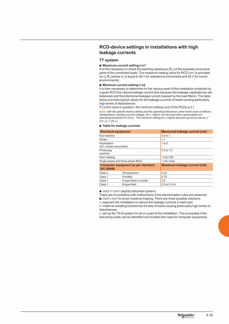
E-35
RCD-device settings in installations with high leakage currentsTT system
b Maximum current setting IDn1It is first necessary to check the earthing resistance (RT) of the exposed conductive parts of the connected loads. The maximum setting value for RCD IDn1 is provided by UL/RT (where UL is equal to 50 V for standard environments and 25 V for humid environments).
b Minimum current setting IDn2It is then necessary to determine for the various parts of the installation protected by a given RCD the natural leakage current (low because the leakage capacitances are balanced) and the intentional leakage current (caused by the load filters). The table below provides typical values for the leakage currents of loads causing particularly high levels of disturbances.If II is the value in question, the minimum setting IDn2 of the RCDs is 2 II.Note: with the specific factory setting and the operating tolerances under worst-case conditions (temperature, auxiliary-source voltage, etc.), Vigirex can be used with a guaranteed non-operating threshold of 0.8 IDn . The minimum setting for a Vigirex devices can be as low as II /0.8, i.e. 1.25 x II .
b Table for leakage currents
Electrical equipment Measured leakage current (mA)Fax machine 0.5 to 1Printer < 1Workstation(UC, screen and printer)
1 to 3
Photocopy machine
0.5 to 1.5
Floor heating 1 mA / kWSingle-phase and three-phase filters 1 mA / loadComputer equipment as per standard IEC 60950
Maximum leakage current (mA)
Class 2 All equipment 0.25Class 1 Portable 0.75Class 1 A-type fixed or mobile 3.5Class 1 B-type fixed 3.5 or 5 % In
b IDn2 << IDn1 (slightly disturbed system)There are no problems with malfunctions if the discrimination rules are observed.
b IDn2 ≈ IDn1 to avoid nuisance tripping. There are three possible solutions: v segment the installation to reduce the leakage currents in each part v install an isolating transformer for sets of loads causing particularly high levels of
disturbances v set up the TN-S system for all or a part of the installation. This is possible if the
disturbing loads can be identified and located (the case for computer equipment).
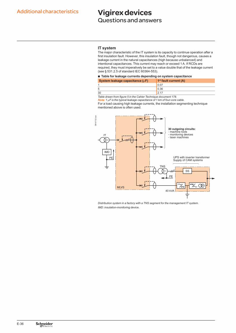
E-36
IT systemThe major characteristic of the IT system is its capacity to continue operation after a first insulation fault. However, this insulation fault, though not dangerous, causes a leakage current in the natural capacitances (high because unbalanced) and intentional capacitances. This current may reach or exceed 1 A. If RCDs are required, they must imperatively be set to a value double that of the leakage current (see § 531.2.5 of standard IEC 60364-553).
b Table for leakage currents depending on system capacitanceSystem leakage capacitance (mF) 1st fault current (A)
1 0.075 0.3630 2.17Table drawn from figure 5 in the Cahier Technique document 178.Note: 1 mF is the typical leakage capacitance of 1 km of four-core cable.For a load causing high leakage currents, the installation segmenting technique mentioned above is often used.
DB
1071
22.e
ps
Distribution system in a factory with a TNS segment for the management IT system.IMD: insulation-monitoring device.
Additional characteristics Vigirex devicesQuestions and answers
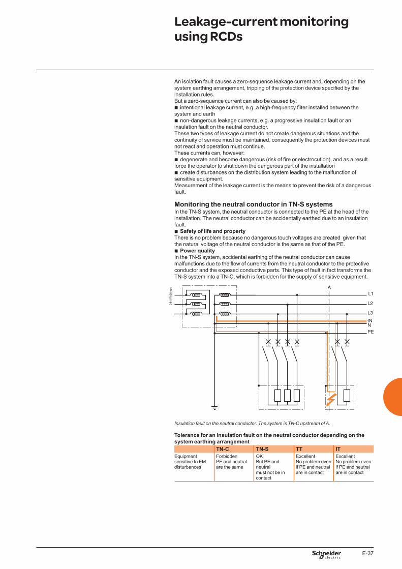
E-37
An isolation fault causes a zero-sequence leakage current and, depending on the system earthing arrangement, tripping of the protection device specified by the installation rules. But a zero-sequence current can also be caused by:
b intentional leakage current, e.g. a high-frequency filter installed between the system and earth
b non-dangerous leakage currents, e.g. a progressive insulation fault or an insulation fault on the neutral conductor. These two types of leakage current do not create dangerous situations and the continuity of service must be maintained, consequently the protection devices must not react and operation must continue.These currents can, however:
b degenerate and become dangerous (risk of fire or electrocution), and as a result force the operator to shut down the dangerous part of the installation
b create disturbances on the distribution system leading to the malfunction of sensitive equipment.Measurement of the leakage current is the means to prevent the risk of a dangerous fault.
Monitoring the neutral conductor in TN-S systemsIn the TN-S system, the neutral conductor is connected to the PE at the head of the installation. The neutral conductor can be accidentally earthed due to an insulation fault.
b Safety of life and propertyThere is no problem because no dangerous touch voltages are created given that the natural voltage of the neutral conductor is the same as that of the PE.
b Power qualityIn the TN-S system, accidental earthing of the neutral conductor can cause malfunctions due to the flow of currents from the neutral conductor to the protective conductor and the exposed conductive parts. This type of fault in fact transforms the TN-S system into a TN-C, which is forbidden for the supply of sensitive equipment.
DB
1070
28.e
ps
Insulation fault on the neutral conductor. The system is TN-C upstream of A.
Tolerance for an insulation fault on the neutral conductor depending on the system earthing arrangement
TN-C TN-S TT ITEquipment sensitive to EM disturbances
ForbiddenPE and neutralare the same
OKBut PE and neutralmust not be in contact
ExcellentNo problem even if PE and neutral are in contact
ExcellentNo problem even if PE and neutral are in contact
Leakage-current monitoring using RCDs
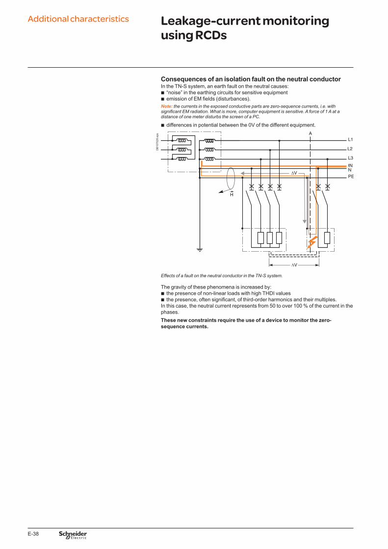
E-38
Additional characteristics
Consequences of an isolation fault on the neutral conductorIn the TN-S system, an earth fault on the neutral causes:
b “noise” in the earthing circuits for sensitive equipment b emission of EM fields (disturbances).
Note: the currents in the exposed conductive parts are zero-sequence currents, i.e. with significant EM radiation. What is more, computer equipment is sensitive. A force of 1 A at a distance of one meter disturbs the screen of a PC.
b differences in potential between the 0V of the different equipment.
DB
1070
29.e
ps
Effects of a fault on the neutral conductor in the TN-S system.
The gravity of these phenomena is increased by: b the presence of non-linear loads with high THDI values b the presence, often significant, of third-order harmonics and their multiples.
In this case, the neutral current represents from 50 to over 100 % of the current in the phases.These new constraints require the use of a device to monitor the zero-sequence currents.
Leakage-current monitoring using RCDs
E-39
Measurement of leakage currents b Management of leakage currents
RMH and RM12T devices provide the means to monitor circuit loading and equipment layout and make sure the leakage currents are distributed correctly and do not disturb the protection system.
b Table for leakage currentsElectrical equipment Measured leakage current (mA)
Fax machine 0.5 to 1Printer < 1Workstation (UC, screen and printer) 1 to 3Photocopy machine 0.5 to 1.5Floor heating 1 mA / kWSingle-phase and three-phase filters 1 mA / loadComputer equipment as per standard IEC 60950
Maximum leakage current (mA)
Class 2 All equipment 0.25Class 1 Portable 0.75Class 1 A-type fixed or mobile (1) 3.5Class 1 B-type fixed (2) 3.5 or 5 % In(1) A-type equipment: equipment intended for connection to the electrical installation of building via a non-industrial outlet, a non-industrial connector or both.(2) B-type equipment: equipment intended for connection to the electrical installation of building via an industrial outlet, an industrial connector or both in compliance with standard IEC �0�09 or similar national standards.
In addition to sensitive equipment and loads, the lighting circuits must also be monitored.The starters for fluorescent lighting have more or less significant levels of natural leakage current. Damage to a starter often causes a major increase in the leakage current.
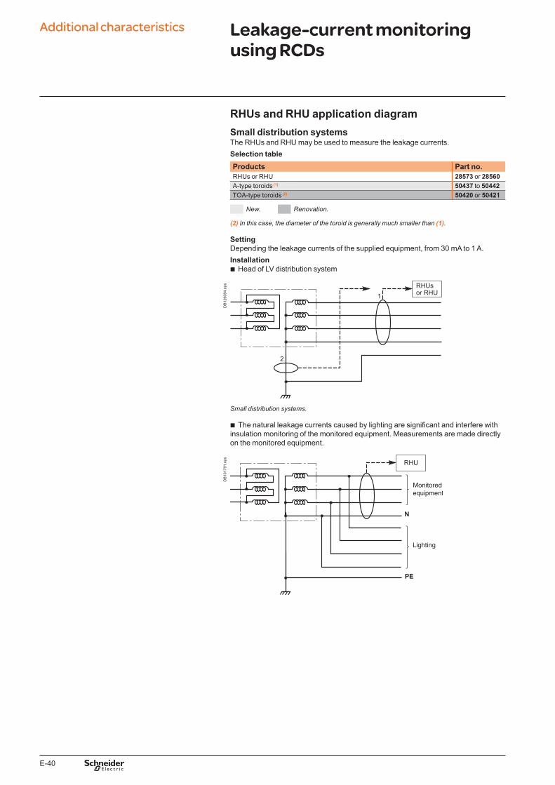
E-40
Additional characteristics
RHUs and RHU application diagramSmall distribution systemsThe RHUs and RHU may be used to measure the leakage currents.Selection tableProducts Part no.RHUs or RHU 28573 or 28560A-type toroids (1) 50437 to 50442TOA-type toroids (2) 50420 or 50421
New. Renovation.
(2) In this case, the diameter of the toroid is generally much smaller than (1).
SettingDepending the leakage currents of the supplied equipment, from 30 mA to 1 A.Installation
b Head of LV distribution system
DB
1260
84.e
ps
Small distribution systems.
b The natural leakage currents caused by lighting are significant and interfere with insulation monitoring of the monitored equipment. Measurements are made directly on the monitored equipment.
DB
1017
91.e
ps
Leakage-current monitoring using RCDs
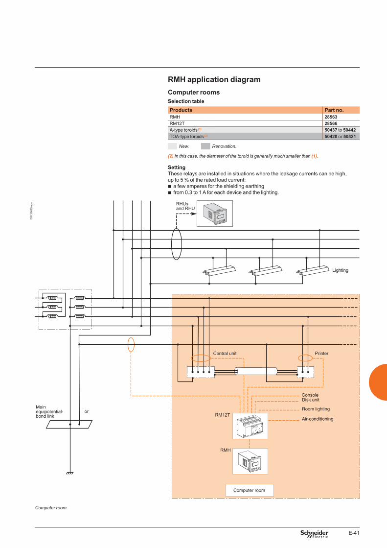
E-41
RMH application diagramComputer roomsSelection tableProducts Part no.RMH 28563RM12T 28566A-type toroids (1) 50437 to 50442TOA-type toroids (2) 50420 or 50421
New. Renovation.
(2) In this case, the diameter of the toroid is generally much smaller than (1).
SettingThese relays are installed in situations where the leakage currents can be high, up to 5 % of the rated load current:
b a few amperes for the shielding earthing b from 0.3 to 1 A for each device and the lighting.
Vigirex RM12T
OK
Vigirex
RMU
VigirexRHUs
OK
Vigirex
RMU
DB
1260
85.e
ps
Computer room.
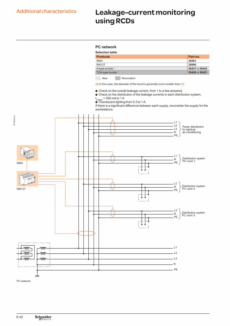
E-42
Additional characteristics
PC networkSelection tableProducts Part no.RMH 28563RM12T 28566A-type toroids (1) 50437 to 50442TOA-type toroids (2) 50420 or 50421
New Renovation
(2) In this case, the diameter of the toroid is generally much smaller than (1).
b Check on the overall leakage current, from 1 to a few amperes b Check on the distribution of the leakage currents in each distribution system,
Ileakage = 300 mA to 1 A b Fluorescent lighting from 0.3 to 1 A.
If there is a significant difference between each supply, reconsider the supply for the workstations.
Vigirex RH99M
Vigirex RM12T
OK
Vigirex
RMU
DB
1260
86.e
ps
PC network.
Leakage-current monitoring using RCDs

E-43
Instantaneous relay, IDn setting = 30 mA Instantaneous relay, IDn setting > 30 mA
DB
1070
39.e
ps
DB
1071
30.e
ps
Non-operating time.
Operating time.
Total break time.
Frequency filtering Delayed relay for IDn > 30 mA
DB
1069
59.e
ps
DB
1074
40.e
ps
ExampleAt 50 Hz, the tripping threshold is IDn.At 900 Hz, the tripping threshold is k x IDn (where k = 5).
Tripping curves and frequency filteringRH10, RH21, RH68, RH86 and RH99
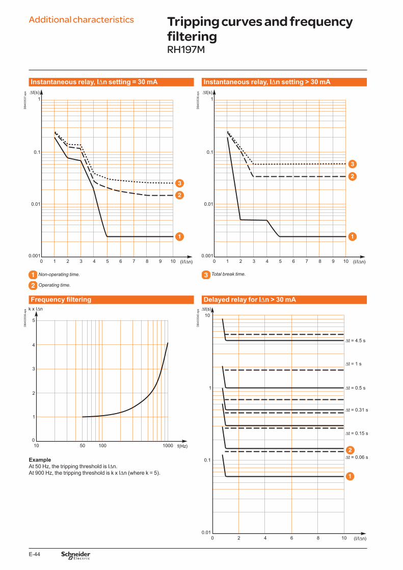
E-44
Additional characteristics
Instantaneous relay, IDn setting = 30 mA Instantaneous relay, IDn setting > 30 mA
DB
4035
37.e
ps
DB
4035
38.e
ps
Non-operating time.
Operating time.
Total break time.
Frequency filtering Delayed relay for IDn > 30 mA
DB
4035
39.e
ps
DB
4035
40.e
ps
ExampleAt 50 Hz, the tripping threshold is IDn.At 900 Hz, the tripping threshold is k x IDn (where k = 5).
Tripping curves and frequency filteringRH197M
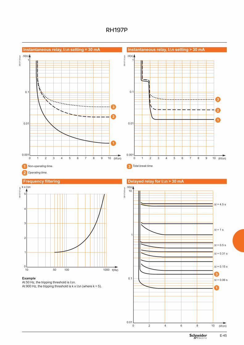
E-45
Instantaneous relay, IDn setting = 30 mA Instantaneous relay, IDn setting > 30 mA
DB
1071
29.e
ps
DB
1071
32.e
ps
Non-operating time.
Operating time.
Total break time.
Frequency filtering Delayed relay for IDn > 30 mA
DB
1071
27.e
ps
DB
1074
38.e
ps
ExampleAt 50 Hz, the tripping threshold is IDn.At 900 Hz, the tripping threshold is k x IDn (where k = 5).
RH197P
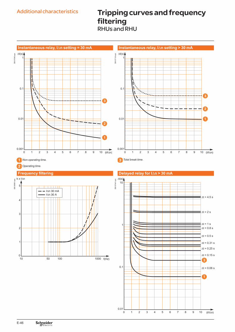
E-46
Additional characteristics
Instantaneous relay, IDn setting = 30 mA Instantaneous relay, IDn setting > 30 mA
DB
1070
40.e
ps
DB
1071
30.e
ps
Non-operating time.
Operating time.
Total break time.
Frequency filtering Delayed relay for IDn > 30 mA
DB
1069
61.e
ps
DB
1074
41.e
ps
Tripping curves and frequency filteringRHUs and RHU

F-1
Vigirex Catalogue numbers
Functions and characteristics A-1Installation recommendations B-1Dimensions and connection C-1Wiring diagrams D-1Additional characteristics E-1
Residual-current protection relays F-2
Residual-current protection relays or monitoring relays F-4
Toroids and rectangular sensors, communication module, accessories F-5
F-2
Catalogue numbers
RH10 with local manual fault resetSystem to be protected LV y 1000 V RH10M RH10P
Vigirex RH10M
DB
1260
88.e
ps
1A/inst
Test no trip
Test
Reset
Vigirex RH10P DB
1260
89.e
ps
DIN-rail mount. Front-panel mount.
Sensitivity 0.03 A - instantaneousPower supply 12 to 24 V AC -12 to 48 V DC 50/60 Hz 56100 56200
110 to 130 V AC 50/60 Hz 56120 56220220 to 240 V AC 50/60/400 Hz 56130 56230380 to 415 V AC 50/60 Hz 56140 56240440 to 525 V AC 50/60 Hz 56150
Sensitivity 0.05 A - instantaneousPower supply 110 to 130 V AC 50/60 Hz 56121
220 to 240 V AC 50/60/400 Hz 56131Sensitivity 0.1 A - instantaneous
Power supply 12 to 24 V AC - 12 to 48 V DC 50/60 Hz 56102 56202110 to 130 V AC 50/60 Hz 56122 56222220 to 240 V AC 50/60/400 Hz 56132 56232380 to 415 V AC 50/60 Hz 56142 56242
Sensitivity 0.25 A - instantaneous Power supply 220 to 240 V AC 50/60/400 Hz 56134 56234Sensitivity 0.3 A - instantaneous
Power supply 12 to 24 V AC - 12 to 48 V DC 50/60 Hz 56105 56205110 to 130 V AC 50/60 Hz 56125 56225220 to 240 V AC 50/60/400 Hz 56135 56235380 to 415 V AC 50/60 Hz 56145 56245
Sensitivity 0.5 A - instantaneous Power supply 12 to 24 V AC - 12 to 48 V DC 50/60 Hz 56106 56206
110 to 130 V AC 50/60 Hz 56126 56226220 to 240 V AC 50/60/400 Hz 56136 56236380 to 415 V AC 50/60 Hz 56146 56246440 to 525 V AC 50/60 Hz 56156
Sensitivity 1 A - instantaneous Power supply 12 to 24 V AC - 12 to 48 V DC 50/60 Hz 56107 56207
110 to 130 V AC 50/60 Hz 56127 56227220 to 240 V AC 50/60/400 Hz 56137 56237380 to 415 V AC 50/60 Hz 56147 56247440 to 525 V AC 50/60 Hz 56157
RH21 with local manual fault resetSystem to be protected LV y 1000 V RH21M RH21P
Vigirex RH21M
DB
1260
90.e
ps
Vigirex RH21P DB
1260
91.e
ps
DIN-rail mount. Front-panel mount.
Sensitivity 0.03 A - instantaneous Sensitivity 0.3 A - instantaneous or with 0.06 s time delay
Power supply 12 to 24 V AC - 12 to 48 V DC 50/60 Hz 56160 56260110 to 130 V AC 50/60 Hz 56162 56262220 to 240 V AC 50/60/400 Hz 56163 56263380 to 415 V AC 50/60 Hz 56164 56264440 to 525 V AC 50/60 Hz 56165 56265
Residual-current protection relays

F-3
RH68 with local manual fault resetSystem to be protected LV y 1000 V RH68M
RH68M Vigirex
DB
4157
34.e
ps
DIN-rail mount.
Sensitivity 0.03 A to 30 A - instantaneous or with 0 to 4.5 s time delayPower supply 220 to 240 V AC 50/60/400 Hz 56168RH86 with local manual fault reset
System to be protected LV y 1000 V RH86M RH86P
RH86M Vigirex
DB
4157
33.e
ps
RH86P Vigirex DB
4157
32.e
ps
DIN-rail mount. Front-panel mount.
Sensitivity 0.03 A to 30 A - instantaneous or with 0 to 4.5 s time delayPower supply 220 to 240 V AC 50/60/400 Hz 56500 56502RH99 with local manual fault reset
System to be protected LV y 1000 V RH99M RH99P
Vigirex RH99M
DB
1260
92.e
ps
Vigirex RH99P DB
1260
93.e
ps
DIN-rail mount. Front-panel mount.
Sensitivity 0.03 A to 30 A - instantaneous or with 0 to 4.5 s time delayPower supply 12 to 24 V AC - 12 to 48 V DC 50/60 Hz 56170 56270
110 to 130 V AC 50/60 Hz 56172 56272220 to 240 V AC 50/60/400 Hz 56173 56273380 to 415 V AC 50/60 Hz 56174 56274440 to 525 V AC 50/60 Hz 56175 56275
RH197 with local manual or automatic fault reset (1)
System to protected LV y 1000 V RH197M RH197P
DB
4032
06.e
ps
.03.05.075
.1.1 .15.2
.3
x1
0.15
.25.5 1
2.5
5
20%
30%
40%
50%
on
Fault
ResetTest
IEC 60947-2 / M
Vigirex RH197P
DB
1260
94.e
ps
DIN-rail mount. Front-panel mount.
Alarm: 50 % of fault threshold - instantaneous Fault: sensitivity 0.03 A to 30 A - instantaneous or with 0 to 4.5 s time delay
Single-phase power supply 48 V AC - 24 to 130 V DC 50/60 Hz 56515 56505110 to 130 V AC (2) 50/60 Hz 56516 56506220 to 240 V AC (2) 50/60/400 Hz 56517 56507380 to 415 V AC (2) 50/60 Hz 56518 56508
Alarm: 100 % of fault threshold - instantaneous Fault: sensitivity 0.03 A to 30 A - instantaneous or with 0 to 4.5 s time delay
Single-phase power supply 48 V AC - 24 to 130 V DC 50/60 Hz 56515 56510110 to 130 V AC (2) 50/60 Hz 56516 56511220 to 240 V AC (2) 50/60/400 Hz 56517 56512380 to 415 V AC (2) 50/60 Hz 56518 56513
(1) Selected via a switch.(2) RH197M: 110 V, 2�0 V, 400 V.

F-4
Catalogue numbers
Monitoring relaysRH99 with automatic fault reset
System to be protected LV y 1000 V RH99M RH99P
Vigirex RH99M
DB
1260
92.e
ps
Vigirex RH99P DB
1260
93.e
ps
DIN-rail mount. Front-panel mount.
Sensitivity 0.03 A - instantaneous Sensitivity 0.1 A to 30 A - instantaneous or with 0 s to 4.5 s time delay
Power supply 12 to 24 V AC - 12 to 48 V DC 50/60 Hz 56190 56290110 to 130 V AC 50/60 Hz 56192 56292220 to 240 V AC 50/60/400 Hz 56193 56293380 to 415 V AC 50/60 Hz 56194 56294440 to 525 V AC 50/60 Hz 56195
RMH and multiplexer RM12T (communicating)System to be monitored LV y 1000 V RM12T RMH
Vigirex RM12T
DB
1260
96.e
ps
OK
Vigirex
RMH
DB
4190
86.e
ps
DIN-rail mount. Front-panel mount.
Pre-Alarm: sensitivity 0.015 A to 30 A - instantaneous or with 0 to 5 s time delay Alarm: sensitivity 0.03 A to 30 A - instantaneous or with 0 to 5 s time delay
Single-phase power supply 220 to 240 V AC 50/60/400 Hz 28566 LV481004
Residual-current protection relaysRHUs with local manual fault reset
System to be protected LV y 1000 V RHUs
OK
Vigirex
RMH
DB
4190
86.e
ps
Alarm: sensitivity 0.015 A to 30 A - instantaneous or with 0 to 4.5 s time delay Fault: sensitivity 0.03 A to 30 A - instantaneous or with 0 to 4.5 s time delay
Single-phase power supply 110 to 130 V AC 50/60 Hz LV481000220 to 240 V AC 50/60/400 Hz LV481001
RHU with local manual fault reset (communicating)System to be protected LV y 1000 V RHU
OK
Vigirex
RMH
DB
4190
86.e
ps
Alarm: sensitivity 0.015 A to 30 A - instantaneous or with 0 to 4.5 s time delay Fault: sensitivity 0.03 A to 30 A - instantaneous or with 0 to 4.5 s time delay
Single-phase power supply 110 to 130 V AC 50/60 Hz LV481002220 to 240 V AC 50/60/400 Hz LV481003
Residual-current protection relays or monitoring relays

F-5
SensorsClosed toroids, A-type
DB
1260
98.e
ps Type Ie (A) rated operational current
Inside diameter (mm)
TA30 65 30 50437PA50 85 50 50438IA80 160 80 50439MA120 250 120 50440SA200 400 200 50441GA300 630 300 50442
Accessory for closed toroidsMagnetic ring For TA30 toroid 56055
DB
1070
32.e
ps For PA50 toroid 56056For IA80 toroid 56057For MA120 toroid 56058
Split toroids, TOA-type
DB
4190
87.e
ps Type Ie (A) rated operational current
Inside diameter (mm)
TOA80 160 80 50420TOA120 250 120 50421
Rectangular sensors
DB
1261
00.e
ps Inside dimensions (mm) Ie (A) L1 1600 280 x 115 56053L2 3200 470 x 160 56054
Accessories
DB
1156
20.e
ps 1 screws bag for RHppM and P 56060
Note: sensor-relay link: twisted cable not supplied (see “Installation and connection” chapter).
Toroids and rectangular sensors, communication module, accessories

F-6


Schneider Electric Industries SAS35, rue Joseph MonierCS 3032392506 Rueil Malmaison Cedex France
RCS Nanterre 954 503 439Capital social 896 313 776 €www.schneider-electric.com
12-2015
This document has been printed on ecological paper.
Photos: Schneider ElectricPublishing:
10-31-1247
As standards, specifications and designs change from time to time, please ask for confirmation of the information given in this publication.
Publication: Schneider Electric Industries SAS
AR
T834
989
© 2
016
- Sch
neid
er E
lect
ric -
All
right
s re
serv
ed.
LVPED208009EN
Recommended