OPERATIONS AND MAINTENANCE MANUAL
GROUNDWATER TREATMENT FACILITIES #1 AND #2 SITE-WIDE GROUNDWATER AND CURRICULUM CENTER
SVE REMEDIAL ACTIONS TUTU WELLFIELD SUPERFUND SITE ST THOMAS, U.S. VIRGIN ISLANDS
Submitted to:
CDM Federal Programs Corporation 14 Wall Street, Suite 1702
New York, NY 10005
Submitted by:
Arrowhead Contracting, Inc. 10981 Eicher Dr.
Lenexa, Kansas 66219
February 2013
Revision 1

OPERATIONS AND MAINTENANCE MANUAL GROUNDWATER TREATMENT FACILITIES #1 AND #2
SITEWIDE GROUNDWATER AND CURRICULUM CENTER SVE REMEDIAL ACTIONS TUTU WELLFIELD SUPERFUND SITE ST THOMAS, U.S. VIRGIN ISLANDS
Submitted to:
CDM Federal Programs Corporation 14 Wall Street, Suite 1702
New York, NY 10005
Submitted by:
Arrowhead Contracting, Inc. 10981 Eicher Dr.
Lenexa, Kansas 66219 February 2013
Revision 1
Reviewed/
Concurred by: Date: February 7, 2013 Greg Wallace, R.G. Project Manager

O and M Manual - Rev 1.doc i
Table of Contents List of Tables ................................................................................................................................. iv
List of Drawings ............................................................................................................................. v
List of Appendices ......................................................................................................................... vi
List of Acronyms .......................................................................................................................... vii
List of Acronyms (continued) ...................................................................................................... viii
1.0 Introduction ...................................................................................................................... 1-1
1.1 Document Organization ....................................................................................... 1-1
1.2 Supporting Documents......................................................................................... 1-2
1.3 O&M Staffing Plan .............................................................................................. 1-2
1.4 Project Directory .................................................................................................. 1-3
2.0 Background Information and Overview .......................................................................... 2-1
2.1 Site Description .................................................................................................... 2-1
2.2 Remedial Action Objectives ................................................................................ 2-1
2.3 GWTF Design Summary ..................................................................................... 2-2
2.4 O&M Requirements ............................................................................................. 2-6
2.4.1 Operations ................................................................................................ 2-6
2.4.2 Maintenance ............................................................................................. 2-7
2.4.3 Sampling and Monitoring ........................................................................ 2-8
2.4.3.1 Performance and Compliance Monitoring............................... 2-9 2.4.3.2 Sitewide Groundwater Monitoring .......................................... 2-9
3.0 Control Systems Description ........................................................................................... 3-1
3.1 Control Panels ...................................................................................................... 3-1
3.2 Control Logic Overview ...................................................................................... 3-1
3.3 Control System Functionality Overview ............................................................. 3-3
3.4 Human-Machine Interface (HMI) ........................................................................ 3-4
3.4.1 MAIN Screen ........................................................................................... 3-4
3.4.2 MOTORS Screen ..................................................................................... 3-8
3.4.3 PID Screen ............................................................................................. 3-10
3.4.4 ALARMS Screen ................................................................................... 3-13
3.4.5 TREND Screens ..................................................................................... 3-14
3.4.6 Data Logs ............................................................................................... 3-16
3.4.7 Alarm Logs ............................................................................................ 3-17
3.5 Autodialer .......................................................................................................... 3-18
3.6 Remote Access ................................................................................................... 3-18

O and M Manual - Rev 1.doc ii
4.0 Initial Set-Up Procedures ................................................................................................. 4-1
4.1 Control Panels ...................................................................................................... 4-1
4.2 Bag Filters ............................................................................................................ 4-2
4.3 Transfer Pumps .................................................................................................... 4-2
4.4 Air Strippers ......................................................................................................... 4-3
4.5 Submersible Well Pumps ..................................................................................... 4-3
4.6 SVE System (Facility #1) .................................................................................... 4-4
4.7 Chemical Feed Systems ....................................................................................... 4-4
4.8 Off-Gas Treatment System (Facility #1) ............................................................. 4-5
4.9 Heat Exchanger (Facility #1) ............................................................................... 4-5
4.10 Miscellaneous Equipment .................................................................................... 4-5
5.0 Systems Operating Procedures ........................................................................................ 5-1
5.1 Preliminary Checks Prior to System Start-Up ..................................................... 5-1
5.2 Full Automatic Start-Up and Operation ............................................................... 5-1
5.3 Automatic Startup and Operation of Select Equipment ....................................... 5-4
5.4 Manual Speed Control for Submersible Well Pumps .......................................... 5-5
5.5 Operation with Equalization Tank Bypass .......................................................... 5-5
5.6 Routine Operations .............................................................................................. 5-6
5.7 Operator Shutdown .............................................................................................. 5-7
5.8 Automatic Shutdown on Alarm Condition .......................................................... 5-7
5.9 Emergency Shutdown .......................................................................................... 5-8
6.0 Maintenance Procedures .................................................................................................. 6-1
6.1 Preventative Maintenance and Lubrication Schedules ........................................ 6-1
6.2 Replacement of Consumable Items ..................................................................... 6-1
6.2.1 Bag Filters ................................................................................................ 6-1
6.2.2 Chemical Additives .................................................................................. 6-2
6.2.3 Off-Gas Treatment Media ........................................................................ 6-2
6.3 Extraction Well Maintenance .............................................................................. 6-2
6.4 Shutdown for Maintenance, Repair, or Replacement .......................................... 6-3
6.4.1 Bag Filters ................................................................................................ 6-3
6.4.2 Transfer Pumps ........................................................................................ 6-3
6.4.3 Air Strippers ............................................................................................. 6-3
6.4.4 Submersible Well Pumps ......................................................................... 6-3
6.4.5 SVE System ............................................................................................. 6-3
6.4.6 Chemical Feed Systems ........................................................................... 6-3
6.4.7 Off-Gas Treatment System ...................................................................... 6-3

O and M Manual - Rev 1.doc iii
6.4.8 Heat Exchanger ........................................................................................ 6-4
6.5 Spare Parts List .................................................................................................... 6-5
7.0 Inspection and Monitoring Procedures ............................................................................ 7-1
7.1 Extraction Wells and Pumps ................................................................................ 7-1
7.2 Conveyance Piping .............................................................................................. 7-1
7.3 Treatment Plants .................................................................................................. 7-2
8.0 Troubleshooting Guidelines ............................................................................................. 8-1
9.0 Sampling and Monitoring Activities ................................................................................ 9-1
10.0 Health and Safety Guidelines ......................................................................................... 10-1
10.1 Physical and Chemical Hazards ......................................................................... 10-1
10.2 Control Measures and Precautions ..................................................................... 10-2
11.0 Recordkeeping and Reporting........................................................................................ 11-1
11.1 Operations Records ............................................................................................ 11-1
11.2 Maintenance Records ......................................................................................... 11-1
11.3 Monthly Operations Summary Report ............................................................... 11-2
12.0 References ...................................................................................................................... 12-1

O and M Manual - Rev 1.doc iv
List of Tables
Table Title
1-1 Project O&M Directory
1-2 Vendor O&M Directory
2-1 TPDES Storm Sewer / Surface Water Discharge Criteria
2-2 DPNR Air Discharge Criteria
2-3 Equipment List, Groundwater Extraction and Treatment – GWTF #1
2-4 Equipment List, Soil Vapor Extraction System – GWTF #1
2-5 Equipment List, Off-Gas Treatment System – GWTF #1
2-6 Equipment List, Groundwater Extraction and Treatment – GWTF #2
2-7 Piping and Valve Nomenclature – GWTF #1
2-8 Piping and Valve Nomenclature – GWTF #2
2-9 Sampling and Monitoring Schedule for Long-Term O&M
2-10 Sampling and Monitoring Schedule for Sitewide Groundwater
3-1 Control System Interlocks – GWTF #1
3-2 Control System Interlocks – GWTF #2
3-3 Control Tag Database – GWTF #1
3-4 Control Tag Database – GWTF #2
5-1 Routine Operating Parameters – GWTF #1
5-2 Routine Operating Parameters – GWTF #2
6-1 Routine and Preventative Maintenance Schedule – GWTF #1
6-2 Routine and Preventative Maintenance Schedule – GWTF #2
6-3 Spare Parts List
7-1 Routine Inspection, Monitoring, and Maintenance Schedule
8-1 General Troubleshooting Guidelines – GWTF #1
8-2 General Troubleshooting Guidelines – GWTF #2

O and M Manual - Rev 1.doc v
List of Drawings Drawing Title
2-1 Site Layout and Yard Piping – GWTF #1
2-2 Site Layout and Yard Piping – GWTF #2
2-3 Equipment Arrangement and Yard Piping – GWTF #1
2-4 Equipment Arrangement and Yard Piping – GWTF #2
2-5 Recovery Well and Vault Details – RW-6, RW-9, RW-1, and RW-1S
2-6 Recovery Well and Vault Details – RW-7
2-7 SVE Well and Vault Details – SVE-1
2-8 Pull Box Details – GWTF #1 and GWTF #2
2-9 Piping, Instrumentation, and Control Logic Diagram – GWTF #1
2-10 Piping, Instrumentation, and Control Logic Diagram – GWTF #1
2-11 Piping, Instrumentation, and Control Logic Diagram – GWTF #1
2-12 Piping, Instrumentation, and Control Logic Diagram – GWTF #2
2-13 Piping, Instrumentation, and Control Logic Diagram – GWTF #2
2-14 Piping and Valve Nomenclature – GWTF #1
2-15 Piping and Valve Nomenclature – GWTF #1
2-16 Piping and Valve Nomenclature – GWTF #1
2-17 Piping and Valve Nomenclature – GWTF #2
2-18 Piping and Valve Nomenclature – GWTF #2

O and M Manual - Rev 1.doc vi
List of Appendices
Appendix Title
A Equalization Tanks and Vapor Phase Carbon Units (GWTF #1 and #2)
B Transfer Pumps (GWTF #1 and #2)
C Chemical Feed Systems (GWTF #1 and #2)
D Bag Filters (GWTF #1 and #2)
E Air Strippers and Blowers (GWTF #1 and #2)
F Soil Vapor Extraction System (GWTF#1)
G Off-Gas Treatment System (GWTF #1)
H Heat Exchanger (GWTF #1)
I Supervisory Controls and Data Acquisition (GWTF #1 and #2)
J Process Instrumentation and Controls (GWTF #1 and #2)
K Miscellaneous Electrical Equipment (GWTF #1 and #2)
L Submersible Groundwater Pumps and Transducers (GWTF #1 and #2)
M Facility Equipment and Appurtenances (GWTF #1 and #2)
N Field Sampling and Monitoring Equipment (GWTF #1 and #2)
O Chemical Additives (GWTF #1 and #2)
P Air Stripper and Off-Gas Treatment Modeling Data (GWTF #1 and #2)
Q Silencer (GWTF #2)
R O&M Forms and Logs (GWTF #1 and #2)
S Operating Permits (GWTF #1 and #2)
T Recovery Well Construction Logs (GWTF #1 and #2)

O and M Manual - Rev 1.doc
vii
List of Acronyms
amsl Above mean sea level COC chain-of-custody CQCP Contractor Quality Control Plan CV controlled variable CVOC chlorinated volatile organic compound DCE 1,2-dichloroethene DPNR Department of Planning and Natural Resources EPA U.S. Environmental Protection Agency EQ Equalization GAC granular activated carbon gpm gallons per minute GWTF Groundwater Treatment Facility HMI Human-Machine Interface I/O inputs & outputs (PLC I/O) KVA kilovolt-ampere MCL maximum concentration limits O&M operations and maintenance QA Quality Assurance QAPP Quality Assurance Project Plan QC Quality Control OIT Operator Interface Terminal P&ID Process and instrumentation diagram PCE tetrachloroethene PID Proportional-Integral-Derivative PLC Programmable logic controller ppm parts per million ppmv parts per million by volume RA Remedial Action scfm cubic feet per minute at standard conditions SOP Standard Operating Procedure SSHP Site Safety and Health Plan SVE soil vapor extraction TCE trichloroethene TDH total discharge head

O and M Manual - Rev 1.doc
viii
List of Acronyms (continued)
ug/L micrograms per liter UPS Uninterruptible power supply USEPA U.S. Environmental Protection Agency USVI U.S. Virgin Islands VAC volts AC VDC volts DC WAPA Water and Power Authority wc water column

O and M Manual - Rev 1.doc
1-1
1.0 Introduction
This document presents Revision 1 of the Operations and Maintenance (O&M) Manual for
facility operations at the Tutu Wellfield Superfund Site, located in St. Thomas, U.S. Virgin
Islands (USVI). This is Revision 1 to the Final O&M Manual prepared during the Remedial
Action (RA) (Arrowhead 2004). This revision was prepared by the United States Environmental
Protection Agency (EPA) pursuant to Appendix B of the Site Transfer Agreement between the
EPA and USVI. Currently, there are two groundwater facilities are operating at the site. The SVE
and off-gas systems at Facility #1 have been shut down and were taken off-line in April 2006.
1.1 Document Organization
This manual is subdivided into the following sections:
Section 1.0 – Introduction – In addition to presenting the outline for this O&M Manual,
this section presents a list relevant supporting documents, a description of O&M
subcontractor responsibilities, and a project directory.
Section 2.0 – Background Information and Overview – This section presents general
background information about the site and project, including the RA objectives, a
summary of the design of each GWTF, and the requirements for O&M.
Section 3.0 – Control Systems Description – This section provides a discussion of the
control logic and functionality for each system, including the capabilities of each
system’s motor control center.
Section 4.0 – Initial Set-Up Procedures – This section provides procedures for the
initial set-up/start-up of each piece of equipment following installation.
Section 5.0 – Systems Operating Procedures – This section presents the procedures for
operating each GWTF once the equipment is installed and initial set-up is completed.
The primary scenarios for startup, operation, and shutdown are covered.
Section 6.0 – Maintenance Procedures – This section presents the general procedures
for preventative maintenance and inspections to optimize the operation of each system.
For more detailed maintenance information, readers are referred to the manufacturer-
specific O&M literature contained in the appendices.
Section 7.0 – Inspection and Monitoring Procedures – This section presents general
procedures for inspection and monitoring of each system, as part of the routine O&M
program.

O and M Manual - Rev 1.doc
1-2
Section 8.0 – Troubleshooting Guidelines – This section presents general
troubleshooting guidelines in the event of system failure or shutdown. For more detailed
troubleshooting information, readers are referred to the manufacturer-specific O&M
literature contained in the appendices.
Section 9.0 – Sampling and Monitoring Methods – This section provides a general
discussion of the sampling and monitoring activities that will be conducted during the
O&M of each GWTF.
Section 10.0 – Health and Safety Guidelines – This section provides a general
discussion of the health and safety issues associated with the O&M of each GWTF.
Section 11.0 – Recordkeeping and Reporting – This section presents the recordkeeping
and reporting requirements applicable to long-term O&M.
Section 12.0 – References – This section presents a list of references associated with this
O&M Manual.
In addition to the text (described above), this manual contains relevant tables, drawings, and
appendices. Appendices include:
Appendices A – M, Q: manufacturer O&M literature and information for equipment associated with each GWTF, including preventative maintenance schedules, troubleshooting guidelines, and spare parts lists.
Appendix N: manufacturer O&M literature for field sampling and monitoring equipment Appendix O: material safety data sheets (MSDSs) for the chemical additives Appendix P: predictive modeling data for the air stripper and off-gas treatment system Appendix R: relevant forms and logs to be used during O&M Appendix S: copies of the air and water discharge permits Appendix T: copies of the well construction diagrams for each groundwater extraction
well
1.2 Supporting Documents
Sampling and monitoring activities are currently being performed in accordance with the site-
specific Final Quality Assurance Project Plan (QAPP), April 2009 (CDM Smith, 2009).
1.3 O&M Staffing Plan
The staffing requirements for O&M include a project manager and operator. The following
paragraphs summarize the responsibilities associated with each position. Upon transition of
O and M Manual - Rev 1.doc
1-3
ownership to the USVI, the USVI Department of Planning and Natural Resources (DPNR) or
their subcontractor shall be fully responsible for preparing the staffing plan.
Project Superisor/Manager
A supervisory position directing the overall operation, maintenance, monitoring, and
management of groundwater treatment systems.
In charge of developing plans and making sure that the plans are carried out. Supervise
and direct on-site operation of treatment systems. Ensure competency and safety of
operations. Ensure compliance with all permit requirements. In charge of approving all
changes in treatment system operation. Perform other related administrative and
management work, as required. Primary contact to the Contractor.
Operator
A supervisory position directing and performing the day-to-day operations, maintenance,
monitoring, and management of groundwater treatment systems.
In charge of the day-to-day operation, maintenance, monitoring, sampling, and
management of treatment systems, extraction well systems and associated facilities,
attainment of effluent and air discharge requirements, record maintenance, reporting,
waste disposal, and associated on-site operations. Intimately familiar with all permit
regulations and enforcement requirements. Maintains accurate and orderly managed
O&M records. Performs other related work including, administration, budgeting, and
routine office duties, as required.
1.4 Project Directory
Table 1-1 presents a directory (addresses, telephone numbers, and contacts) of the key
organizations, regulators, and property owners associated with the Tutu Wellfield O&M.
Additionally, Table 1-2 is provided as a directory of the primary vendors, suppliers, and
manufacturers of the process equipment and instrumentation.
O and M Manual - Rev 1.doc
2-1
2.0 Background Information and Overview
This section presents general background information about the site and project, including the
RA objectives, a summary of the design of each GWTF, and the requirements for O&M.
2.1 Site Description
The Tutu Wellfield Superfund Site is located in the Anna’s Retreat area, east of the city
Charlotte Amalie on the island of St. Thomas, USVI. The site is situated within the upper
Turpentine Run surface drainage basin. The basin, which covers approximately 2.3 square
miles, trends roughly north-south and is bounded by steep slopes of the surrounding hills. The
site contains a variety of commercial establishments, schools, churches, and residential units.
The project covers of two areas of concern that are being implemented to remediate groundwater
contaminated with chlorinated volatile organic compounds (CVOCs). The Northern Plume is
upgradient, and is located below and adjacent to the Curriculum Center. The Southern Plume is
downgradient and extends to the south of the Esso Tutu Service Station below O’Henry Dry
Cleaners.
2.2 Remedial Action Objectives
The CVOCs found in groundwater at the site include trichloroethene (TCE), tetrachloroethene
(PCE), 1,2-dichloroethene (DCE), and vinyl chloride. Total CVOC concentrations have
exceeded 10 parts per million (ppm) in select groundwater samples. The objectives of the
program are summarized as follows:
Contaminated groundwater in the Northern Plume is extracted, treated, and discharged to
surface water for the purpose of achieving:
- Hydraulic control of and CVOC mass removal from the contamination source
at the Curriculum Center property (GWTF #1)
- Hydraulic control of and CVOC mass removal from the dissolved-phase
plume that extends downgradient of the Curriculum Center, just to the south
of the Esso Tutu Service Station and exceeds 100 ug/L total CVOCs (GWTF
#2).
Groundwater quality will improve in the Northern Plume area over time as a result of
active CVOC mass removal within the capture zone areas of the GWTF extraction

O and M Manual - Rev 1.doc
2-2
systems, and in downgradient areas as a result of hydraulic CVOC source/plume control
and natural attenuation processes.
The soil remedy for the site, consisting of SVE at the Curriculum Center, was
implemented concurrently with the groundwater remedial action. The two remedies were
integrated to combine common components, such as the building enclosures and process
controls. The soil remedy was completed in April 2006, at which point the SVE and off-
gas system components were shut down.
Contaminated groundwater in the Southern Plume will be allowed to naturally attenuate
under closely monitored conditions.
Changes in groundwater quality resulting from groundwater extraction and from natural
attenuation will be closely monitored as part of the site-wide groundwater monitoring
program to:
- Confirm that Northern CVOC source and plume are being hydraulically
controlled and that CVOC concentrations are decreasing in the aquifer over
time
- Confirm that the current Southern Plume area exceeding federal maximum
concentration limits (MCLs) for drinking water is not expanding or moving
beyond its current location and that CVOC concentrations are decreasing in
the aquifer over time.
The cleanup goals for aquifer groundwater quality at the site are the federal MCLs.
Remedial system operation and/or site-wide groundwater monitoring will continue until
these cleanup goals are achieved. Surface water and air discharges from GWTFs shall
comply with locally permitted discharge criteria, as presented in Tables 2-1 and 2-2,
respectively. Copies of the surface water discharge and air emissions permit
equivalencies are provided in Appendix S.
2.3 GWTF Design Summary
Operations at GWTF #1 include groundwater extraction and treatment consistent with the RA
objectives discussed in Section 2.2. The site layout for GWTF #1 is depicted in Drawing 2-1.
GWTF #1 is designed to treat up to 60 gpm of groundwater from a network of three extraction
wells (RW-6, RW-7, and RW-9; refer to Drawings 2-5 and 2-6). The SVE system at GWTF #1
is capable of extracting 130 scfm at –30 in. wc. SVE wells include SVE-1 and RW-7 (refer to
Drawings 2-6 and 2-7). Extraction well RW-7 is a dual-phase well; it is designed and

O and M Manual - Rev 1.doc
2-3
constructed for both groundwater and soil vapor extraction. Extraction well construction logs are
provided in Appendix T. The SVE and off-gas systems were shut down in April 2006.
The overall system design for GWTF #1 incorporates the following pieces of equipment:
Three Grundfos Redi-Flo3 electric submersible well pumps (RW-6, RW-7, and RW-9)
1,000-gallon, cone-bottom equalization (EQ) tank, including a 55-gallon container with
200 lbs vapor phase granular activated carbon (GAC) (only in use when RW-6 is in
operation and influent is passed through EQ tank)
Two centrifugal transfer pumps (maximum flow rate 30 gpm @ 56 ft TDH)
Two chemical feed systems [pH adjustment using muriatic acid and anti-scalant
(sequesterant) addition], including metering pumps and chemical storage drums
Two bag filters
6-tray, low-profile air stripper (rated for 5 – 80 gpm) and regenerative blower (rated at
350 scfm @ –75 in. wc), piped in an induced-draft configuration (refer to Appendix P for
predictive modeling simulations and results)
Air-to-air heat exchanger (aftercooler) - currently in-line but not turned on as part of
operations
Off-gas treatment system, consisting of one vapor phase GAC vessel (5,000 lbs capacity)
and one potassium permanganate-impregnated vessel (7,000 lbs capacity)– currently
offline
Soil vapor extraction system, consisting of a regenerative blower (rated at 140 scfm @ –
70 in. wc) and a 40-gallon moisture separator tank – currently offline and moisture
separator tank removed due to severe rusting
Appurtenances, including air inlet filters, discharge silencers, Y-strainers, vacuum
breaker (anti-siphon), and sample ports
Instrumentation, including temperature gauges, temperature switches, pressure gauges,
pressure switches, flow meters, flow transmitters, and level switches
Motor control centers (see below)
Drawing 2-3 depicts the equipment arrangement, building floor plan, and yard piping for GWTF
#1. The air stripper, transfer pumps, and SVE system are located within the process building.
This building is subdivided into process room and office. The office also houses the control
panels and transformers. The EQ tank, off-gas treatment vessels, and heat exchanger are

O and M Manual - Rev 1.doc
2-4
mounted on concrete pads located outside and adjacent to the process building. Secondary
containment for the EQ tank is provided via a concrete berm along the perimeter of the pad.
Secondary containment for equipment located inside the building is provided by a concrete berm
along the perimeter of the process room. The “treatment plant” is comprised of the process
building, interior equipment, and pad-mounted equipment located outside the building.
Currently extraction well RW-7 is used as the primary extraction well, with RW-9 serving as a
secondary well for use during periods of high groundwater elevations. Extraction well RW-6 is
pumped once per week for about one hour until the well is pumped dry. Contaminated
groundwater is pumped to the treatment plant via a network of underground aboveground yard
piping (refer to Drawings 2-1 and 2-3). Underground piping and electrical conduit pass through
pull boxes (Drawing 2-8) located between the process building and extraction well vaults
(Drawings 2-5 through 2-7). The EQ tank and transfer pumps are currently bypassed under
normal operating conditions, except during operation of RW-6. When the EQ tank is used, the
influent is temporarily stored there prior to being transferred (by the centrifugal transfer pumps)
to the air stripper. Scale inhibitor is injected upstream of the EQ tank. Muriatic acid is added in
the air stripper sump for pH adjustment prior to discharge. The treated water from the air
stripper is then discharged to a local storm sewer inlet (located approximately 300 ft west of the
treatment plant; refer to Drawing 2-1). Contaminated vapors from the air stripper are no longer
routed through the off-gas treatment system, but rather bypass the units which remain on site
without media present in the vessels. The system was taken off-line in April 2006 because it was
determined to no longer be necessary to meet the air permit requirements. The off-gas passes
through the upstream heat exchanger (after-cooler) which no longer requires operation to
maintain air temperatures. The treated air stream is discharged to the atmosphere through a stack
mounted on the side of the process building. The SVE system which consisted of a moisture
separator, particulate filter, regenerative blower and discharge silencer has been offline since
2006.
GWTF #2 (refer to Drawing 2-2) operations consist of groundwater extraction and air stripping.
The influent CVOC concentrations have historically been below permitted air emissions limits,
so off-gas treatment was not required for GWTF #2. GWTF #2 is designed to treat up to 30 gpm
of groundwater from two extraction wells (RW-1 and RW-1S; refer to Drawing 2-5). Extraction
well RW-1 has not been used as part of the remedy. The overall system design for GWTF #2
incorporates the following pieces of equipment:

O and M Manual - Rev 1.doc
2-5
Two Grudfos Redi-Flo3 electric submersible well pumps
500-gallon cone-bottom equalization tank, including a 55-gallon container with 200 lbs
vapor phase GAC – currently offline and in storage
One centrifugal transfer pump (maximum flow rate 30 gpm @ 56 ft TDH)
Two chemical feed systems (pH adjustment using muriatic acid and anti-
scalant/sequesterant addition), including metering pumps and chemical storage drums
Two bag filters
6-tray, low-profile air stripper (rated for 1 – 35 gpm) and regenerative blower (rated at
150 scfm @ –65 in. wc), piped in an induced draft configuration
Appurtenances, including air inlet filters, discharge silencers, Y-strainers, vacuum
breaker (anti-siphon), and sample ports
Instrumentation, including temperature gauges, pressure gauges, pressure switches, flow
meters, flow transmitters, and level switches
Motor control centers (see below)
Drawing 2-4 depicts the equipment arrangement, building floor plan, and yard piping for GWTF
#2. The treatment equipment, including the EQ tank, is located within the process building.
Similar to GWTF #1, the building is subdivided into a process room and office/control room.
Contaminated groundwater from each extraction well passes through a pull box as shown on
Drawing 2-8. Only RW-1S has been operated as part of the remedy. The EQ tank and transfer
pumps are currently bypassed. Influent groundwater is routed though the air stripper followed by
direct discharge of the off-gas to the atmosphere through a stack mounted to the side of the
building. Treated water from the air stripper is discharged to a local storm sewer inlet (located
approximately 150 ft southwest of the treatment plant; refer to Drawing 2-2). A comprehensive
equipment list for GWTF #2 is provided in Table 2-6.
The control systems for GWTF #1 and GWTF #2 are based on a 480-VAC control panel
containing an Operator Interface Terminal (OIT), programmable logic controller (PLC),
Grundfos® CU-300 pump controllers, autodialer, and associated 24VDC power supplies for DC
input/output (I/O) circuits. The facility receives incoming power @ 208VAC, 3Ø from Water
and Power Authority (WAPA) pole-mounted transformers. The electrical drop connects to a
power meter mounted on the poles. Power is brought from the meter underground into each
building where it is split in a wireway to feed a 100A 208VAC lighting distribution panel, P1,

O and M Manual - Rev 1.doc
2-6
and a 75KVA, 3Ø transformer that provides the 480VAC power necessary for the control panel.
The control panel is equipped with its own 7.5KVA transformer to provide 240VAC single-
phase power to the Grundfos® pump controllers and 120VAC power for the OIT, PLC and other
equipment provided in the control panel. Details are provided in the electrical schematics (E-
series drawings) from the set of as-built drawings. Section 3.1 provides further information
regarding the control panel hardware and software. The overall control logic scheme is depicted
graphically in P&ID diagrams, Drawings 2-9 through 2-13.
A standard nomenclature system was developed for the piping, valves, and sample ports at each
GWTF. Drawings 2-14 through 2-18 identifies each pipe run, valve, and sample port according
to this system. Tables 2-7 and 2-8 provide a comprehensive listing of each identifier, including a
nomenclature abbreviation key.
2.4 O&M Requirements
This subsection summarizes the specified requirements for operations, maintenance, sampling
and monitoring to be implemented by the O&M subcontractor.
2.4.1 Operations
The following are the operational requirements applicable to each GWTF:
Operate all equipment, systems, processes, and appurtenances in accordance with the
subcontract agreement, equipment manufacturer’s specifications and O&M instructions,
and the approved O&M Manual.
Extract groundwater on a continuous basis to achieve hydraulic control of the
groundwater CVOC plume at each treatment plant location, and treat groundwater in
accordance with the permitted requirements for surface water and air discharges.
Containerize, characterize, transport, and dispose of all process and sampling waste
residuals at an approved waste disposal facility.
Procure all equipment, spare parts, supplies, and services required for operation,
maintenance, monitoring, and management of the treatment systems.
Manage and maintain an inventory of equipment, spare parts, supplies, and tools required
for continuous operation with minimal downtime.
Monitor treatment system performance, permit compliance, and remedial progress by
collecting specified samples and field measurements (refer to Section 9.0).

O and M Manual - Rev 1.doc
2-7
Prepare operational records and maintain project files (refer to Section 11.0). Prepare
and submit progress reports.
Abide by all permits required to operate and report any non-compliant conditions to
DPNR immediately.
Optimize the use of process equipment and chemicals to minimize operational costs.
Maintain treatment plant uptime in excess of 95% per quarter.
Notify DPNR immediately of any system downtime greater than 24 hours or any non-
compliance with discharge requirements.
2.4.2 Maintenance
The following are the maintenance requirements applicable to each GWTF:
Provide routine, preventative, and corrective maintenance of the GWTFs, including all
processes, equipment, controls, facilities, and appurtenances.
Perform routine, preventative, and corrective maintenance of the GWTFs in accordance
with the equipment manufacturer’s specifications and this O&M Manual.
Store all tools, spare parts, equipment, and supplies in an appropriate storage area at each
GWTF. Manage the inventory and maintenance of such items to minimize downtime for
maintenance.
Maintain good housekeeping practices. Facilities shall be kept neat, organized, and
litter-free. Clean and remove accidental spills.
Containerize, characterize, and promptly dispose all wastes generated at the site, such as
bag filters and tank sediment.
Routinely inspect and maintain the physical condition of exterior facilities, equipment,
and grounds as follows.
- Fencing and locks shall be maintained, and repaired or replaced when necessary.
- Vegetation shall be maintained in a manner that is consistent with the surrounding
and cut when necessary.
- Touch-up painting shall be performed as necessary to prevent corrosion or other
damage associated with environmental exposure.
- Well vaults shall be inspected for surface leaks; access hatch seals and grading shall
be replaced/corrected when needed.

O and M Manual - Rev 1.doc
2-8
- Structural support systems, such as concrete footers, structural anchoring, and guy
wires, shall be periodically checked for structural integrity and adjusted/repaired if
necessary.
- Building openings and access ways, including doors, louvers, fans, air conditioners
shall be periodically checked for leakage and structural integrity; adjust/tighten
hardware, apply caulk, and replace weather stripping when needed.
2.4.3 Sampling and Monitoring
As part of the overall O&M of each system, sampling and monitoring activities will be
conducted to evaluate the following:
Treatment system compliance to confirm that permitted discharge requirements are being
met for surface water and air discharges.
Treatment system performance to confirm that hydraulic control is being maintained and
that treatment systems are operating properly. Subcontractor shall monitor influent flow
and water quality from extraction wells, drawdown and hydraulic control of groundwater,
and unit process performance. Information shall be used to support decisions regarding
adjustments to pumping rates, unit process operations, chemical dosage rates for the
purpose of maximizing remedial performance and minimizing associated operational
costs.
Remedial progress by monitoring changes in source-area and site-wide groundwater
quality, levels, and flow over time. This shall include the areas subjected to groundwater
extraction and treatment and the area subjected to monitored natural attenuation.
Information shall be compared against design assumptions and predictions regarding
remedy performance, and it shall be used to refine such assumptions and predictions and
the environmental monitoring program as more information is gathered.
The long-term O&M phase includes two primary sampling and monitoring programs:
Performance and compliance monitoring Site wide groundwater monitoring
The following subsections present the general sampling and field measurement requirements for
each program. The data quality objectives for performance and compliance monitoring and
sitewide groundwater monitoring are presented in the site-specific QAPP (CDM Smith, 2009).

O and M Manual - Rev 1.doc
2-9
2.4.3.1 Performance and Compliance Monitoring
Performance and compliance monitoring will entail routine sample collection and field
measurements to (1) verify that the treatment systems are performing as designed and (2) verify
compliance with air emissions and surface water discharge permits (refer to Tables 2-1 and 2-2
and Appendix S). The minimum requirements for performance and compliance monitoring are
specified in Table 2-9. All sampling and field measurements shall be performed in accordance
with the site-specific QAPP (CDM Smith, 2009). Water and air/vapor samples that will be
collected and/or monitored as part of long-term O&M performance and compliance monitoring
include:
Groundwater influent samples from each extraction well (VOCs) Treated water effluent samples (VOCs, TOC, and TSS) Air emissions samples from the stack at GWTF #1 (VOCs via Method TO-15)
In addition to water and air samples, operational parameters shall be recorded on a routine basis
from process instruments, meters, and gauges, including the following:
Extraction well water level Extraction well pump flow rate, pressure, and totalized flow Influent flow rate and totalized flow Air stripper influent flow rate and totalized flow Transfer pump(s) discharge pressure and flow rate Bag filter differential pressure Air stripper blower flow rate Air stripper blower vacuum, discharge pressure, and temperature Chemical injection rates Treated water effluent pH Other routine operating parameters (refer to Tables 5-1 and 5-2)
A comprehensive schedule for performance and compliance monitoring (during the first year of
long-term O&M) is presented in Table 2-9.
2.4.3.2 Sitewide Groundwater Monitoring
During long-term O&M, groundwater samples and synoptic water level measurements will be
collected from the sitewide network of groundwater monitoring wells. Groundwater samples
will be collected on an annual basis. Synoptic water levels will be measured on a monthly basis.

O and M Manual - Rev 1.doc
2-10
Additionally, continuous water levels will be recorded from six groundwater monitoring wells
using dedicated pressure transducers with datalogging capabilities. The requirements for
sitewide groundwater monitoring are specified in Table 2-10. All sampling and water level
measurements shall be performed in accordance with the site-specific QAPP (CDM Smith,
2009).

O and M Manual - Rev 1.doc
3-1
3.0 Control Systems Description
This section provides a discussion of the control system logic, programming, and functionality,
including the capabilities of each system’s control panel. The control logic scheme is depicted
graphically on the P&ID diagrams, Drawings 2-9 through 2-13. Control ladder diagrams are
included in Appendix I. It should be noted that the SVE and off-gas systems are currently offline.
3.1 Control Panels
The control panel is equipped with an Allen-Bradley VersaView 1500P 15-inch touch-screen
OIT from which the on-site operator and remote users control and monitor all automated
processes in the system (refer to Appendix I). The VersaView OIT is an industrial computer
with a Windows XP® operating system, a CD-RW drive, 3-1/2 floppy drive, internal modem,
keyboard, mouse, uninterruptible power supply (UPS) and several serial and USB ports for
peripheral devices. The OIT is connected to an Allen-Bradley MicroLogix 1500® PLC located
on a panel behind the OIT. Two 24VDC power supplies are provided in the control panel – one
for analog I/O and the other for the discrete 24VDC circuits shown in the electrical schematics.
The control panel also includes Grundfos® CU300 pump controllers used to control the speed
(pumping rate) of each recovery well pump.
3.2 Control Logic Overview
The control systems for each GWTF are programmed with ladder logic to implement interlocks,
control system processes, cycle process equipment, initiate local and remote alarms, and safely
start up and shut down each system. The control interlocks are depicted graphically in the P&ID
drawings (Drawings 2-9 through 2-13) and listed in Tables 3-1 (GWTF #1) and 3-2 (GWTF #2).
It is important to understand that AUTO mode must be selected in order for the interlocks to
function as designed. Any piece of equipment placed in MAN(ual) mode will have its control
interlocks bypassed.
The control interlocks begin to function automatically upon start up. Clicking the System
START button on the MAIN screen first removes any previously existing stop commands, places
all process equipment in AUTO mode, and then sequentially starts the following in order:

O and M Manual - Rev 1.doc
3-2
GWTF #1
Air stripper blower, B-1 Transfer pump, P-1 – currently bypassed Transfer pump, P-2 – currently bypassed Well pump, P-6 Well pump, P-7 Well pump, P-9 Sequestering agent metering pump, M-2 Muriatic acid metering pump, M-3
GWTF #2
Air stripper blower, B-1 Transfer pump, P-2 – currently bypassed Well pump, P-1– currently unused Well pump, P-1S Sequestering agent metering pump, M-2 Muriatic acid metering pump, M-3
The systems can also be started by the START pushbutton on the front of the control panel.
The START sequence tests for sufficient water levels in the influent EQ tank and recovery wells.
If these levels are above the low level shut-offs for each location, then the pumps will run. Well
pump RW-6 is run manual mode. The pump runs until a low level condition (dry run alarm
condition) is achieved. Upon reaching a low level condition, the CU300 recognizes high amp
draws, and alarms out for a dry run condition. The pump is then turned off. The other well
pumps (P-7, P-9, and P-1S) will automatically go into dynamic level control whereby a preset
water table elevation is maintained using proportional-integral-derivative (PID) level controllers
(refer to Section 3.4.3). In the event any of these levels gets out of control for any reason, high
and low level interlocks are in place to cycle the pumps as necessary and prevent them from
running dry.
The sequestering agent metering pump is interlocked with the recovery well pumps. At least one
recovery well pump must be running for either of these pumps to run in AUTO mode. After
starting, the speed of these pumps is controlled manually at the metering pump based on influent
flow rates and the rate of fouling of the bag filters and the air stripper trays.

O and M Manual - Rev 1.doc
3-3
The muriatic acid metering pump is interlocked with the air stripper influent flow rate . A
minimum flow rate of 5 gpm must be maintained in order for the muriatic acid metering pump to
run in AUTO mode. After starting, the speed of this pump is controlled automatically by its PID
controller to maintain the desired pH setpoint entered by the operator in the PID screen.
All upstream groundwater equipment is interlocked with the air stripper blower, B-1. The air
stripper blower must be running in order for any pumps to run in AUTO mode. In the event of a
normal shutdown in which the operator clicks the System STOP button, all upstream equipment
will shut off immediately while the air stripper blower continues to run for 5 minutes in order to
treat all water remaining on its trays.
In GWTF #1 the heat exchanger (no longer in use), HX-1, is interlocked (no longer
interlocked) with both the air stripper blower (B-1) and the SVE blower (B-2) (no longer in
use). The heat exchanger will not run in AUTO mode unless one of these blowers is running.
The air stripper blower and SVE blower in GWTF #1 have separate shutdown interlocks (no
longer in use) listed in Table 3-1. One interlock in particular is shared between these two
blowers – the heat exchanger high temperature switch, TSH-1625. In the event the heat
exchanger fails or for whatever reason the air temperature leading to the off-gas treatment system
exceeds 120 °F, each blower and the entire facility shuts down (no longer applicable).
3.3 Control System Functionality Overview
The control system is designed for automatic, unattended operation after completing manual set-
up tasks described in Section 4.0. The Human-Machine Interface (HMI) software running on the
OIT provides graphical images of the processes and equipment associated with the facility.
Graphical control panels are provided for each motor which include Windows® push buttons for
START, STOP, AUTO and MAN(ual). System-wide START, STOP & RESET pushbuttons are
also provided on the front of the control panel. All analog inputs used by the system are
displayed in real-time, including groundwater influent flow rate and totalized gallons, recovery
well water levels, chemical metering pump dosage rates, etc. All alarm conditions are displayed
in their appropriate positions in the P&ID formatted MAIN screen and in an ALARM summary
screen from which alarms are acknowledged by the operator. All I/O, including alarm
conditions, is logged in database formatted (*.dbf) files, which can be downloaded to remote PCs
and directly accessed with Microsoft Excel®. All alarm conditions cause autodialer callouts to a

O and M Manual - Rev 1.doc
3-4
select list of respondents via voice, fax or pager (refer to Section 3.5). Remote access is
provided via PC-to-PC direct wireless modem communications using pcAnywhere® remote
access software (refer to Section 3.6). This remote connection gives authorized remote callers
full access to the OIT for control, monitoring and downloading data files.
3.4 Human-Machine Interface (HMI)
The HMI software running on the OIT provides the operator with a process control and
monitoring workstation. It consists of a touch screen industrial computer mounted in the front of
the control panel enclosure (located in the field office portion of each building) running
Rockwell Automation’s RSView32 Works software. The components of the configured
software used by the operator include:
Process control screens depicting all controlled processes in P&ID format Master System Start, System Stop and Reset buttons Pop-up motor control panels for starting, stopping and selecting modes of operation for
individual motors PID controllers for controlling recovery well water levels and effluent pH Alarm display listing any current alarm condition Data logs for all integrated process and status variables Alarm logs listing all previous alarm conditions Trend screens depicting real-time and historical process data in “line graph” format
The HMI software starts automatically whenever power is applied to the OIT. The MAIN
screen, described in Section 3.4.1, is the first to be displayed after power up. All other screens
are accessed through an intuitive menu system of Windows® buttons using a touch screen
pointer, mouse or finger. A detailed discussion of the features and functions of each of the HMI
screens is provided in the ensuing subsections.
3.4.1 MAIN Screen
The MAIN screens shown in Figures 1 and 2 include all of the process equipment controlled by
the PLC, analog and discrete I/O, and alarm conditions for the system. The functionality of this
screen includes images of pumps and blowers that when clicked bring up the pop-up control
panels depicted in Figures 3 and 4, plus each image is animated to indicate whether the motor is
running. Each pop-up panel contains buttons for AUTO or MAN(ual) modes, START and
STOP, and status indicators for the motors and buttons. Additional functionality is provided by
real-time numerical displays of water table elevations in recovery wells, influent groundwater
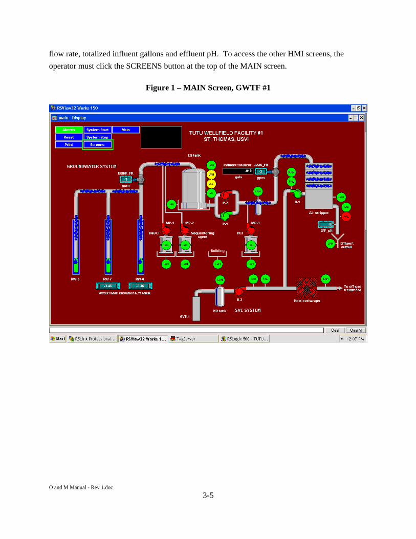
O and M Manual - Rev 1.doc
3-5
flow rate, totalized influent gallons and effluent pH. To access the other HMI screens, the
operator must click the SCREENS button at the top of the MAIN screen.
Figure 1 – MAIN Screen, GWTF #1

O and M Manual - Rev 1.doc
3-6
Figure 2 – MAIN Screen, GWTF #2

O and M Manual - Rev 1.doc
3-7
Figure 3 – MAIN Screen with Pop-Up Motor Control Panels, GWTF #1

O and M Manual - Rev 1.doc
3-8
Figure 4 – MAIN Screen with Pop-Up Motor Control Panels, GWTF #2
3.4.2 MOTORS Screen
The pop-up motor control panels accessed from the MAIN screen are all available on the
MOTORS screen shown in Figures 5 and 6. The motor controls are configured to select AUTO
or MAN(ual) modes of operation for each motor. In AUTO mode all control and safety
interlocks are applied to the motor control circuits. Conversely, in MAN mode no interlocks are
applied. The motor control panels also include status indicators for AUTO / MAN modes,
START and STOP switch status, and the current ON / OFF status of the motor. When the
operator initiates system start up by pressing the System START button available at the top of all
HMI screens the PLC control program automatically places all motors in AUTO mode and then
sequentially starts each piece of equipment beginning with the air stripper blower. When the
operator stops the system with the System STOP button all motors except the air stripper blower
are stopped immediately as though the operator had stopped each individual motor through its
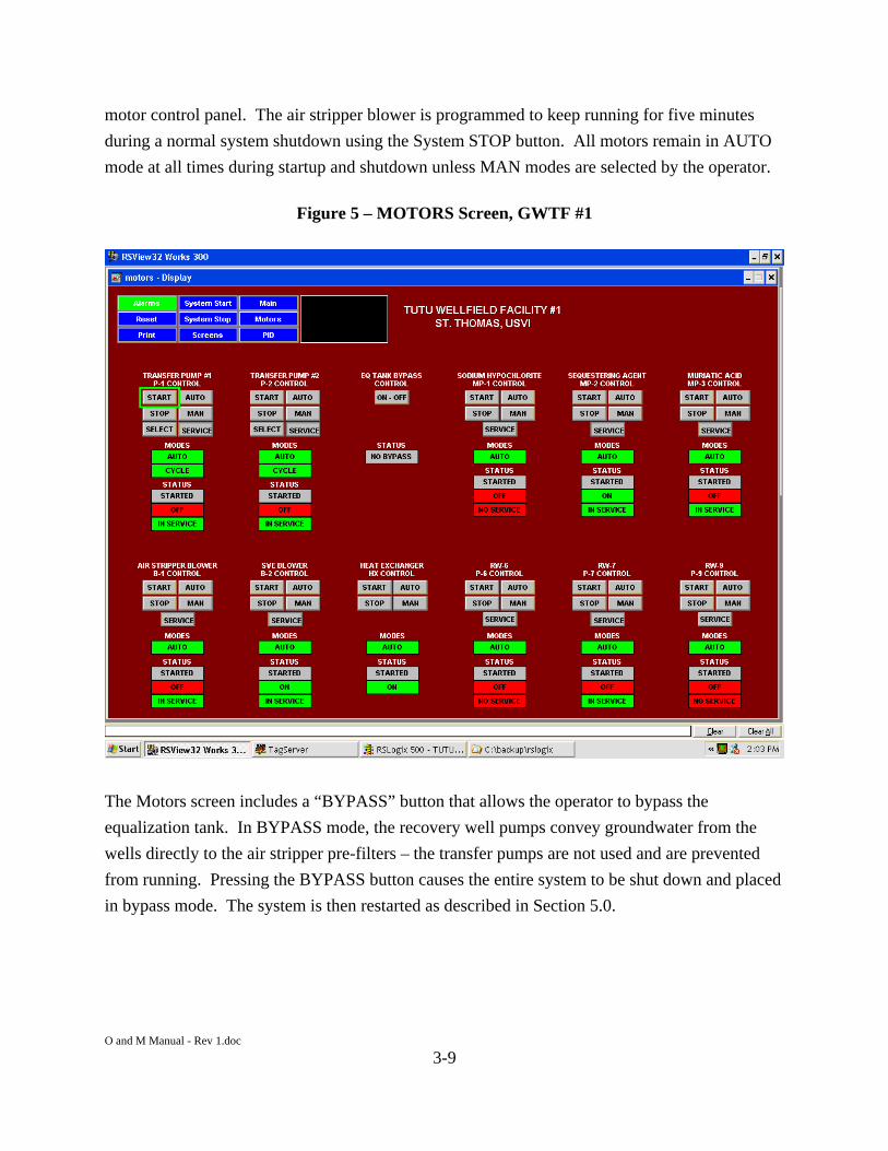
O and M Manual - Rev 1.doc
3-9
motor control panel. The air stripper blower is programmed to keep running for five minutes
during a normal system shutdown using the System STOP button. All motors remain in AUTO
mode at all times during startup and shutdown unless MAN modes are selected by the operator.
Figure 5 – MOTORS Screen, GWTF #1
The Motors screen includes a “BYPASS” button that allows the operator to bypass the
equalization tank. In BYPASS mode, the recovery well pumps convey groundwater from the
wells directly to the air stripper pre-filters – the transfer pumps are not used and are prevented
from running. Pressing the BYPASS button causes the entire system to be shut down and placed
in bypass mode. The system is then restarted as described in Section 5.0.
O and M Manual - Rev 1.doc
3-10
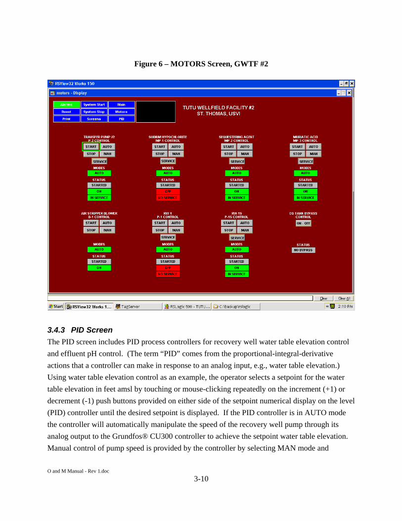
Figure 6 – MOTORS Screen, GWTF #2
3.4.3 PID Screen
The PID screen includes PID process controllers for recovery well water table elevation control
and effluent pH control. (The term “PID” comes from the proportional-integral-derivative
actions that a controller can make in response to an analog input, e.g., water table elevation.)
Using water table elevation control as an example, the operator selects a setpoint for the water
table elevation in feet amsl by touching or mouse-clicking repeatedly on the increment (+1) or
decrement (-1) push buttons provided on either side of the setpoint numerical display on the level
(PID) controller until the desired setpoint is displayed. If the PID controller is in AUTO mode
the controller will automatically manipulate the speed of the recovery well pump through its
analog output to the Grundfos® CU300 controller to achieve the setpoint water table elevation.
Manual control of pump speed is provided by the controller by selecting MAN mode and

O and M Manual - Rev 1.doc
3-11
incrementing or decrementing the pushbuttons on either side of the controlled variable (CV)
numeric display. The CV display is ranged from 0 – 100% which corresponds to a 4 – 20mA
analog output signal to the controlled device, i.e., CU300 or effluent muriatic acid metering
pump.
The PID controllers allow the operator to enable or disable automatic cycling of the controller
between AUTO and MAN modes of operation. During normal operations PID controllers are
cycled automatically (cycling enabled) between AUTO and MAN modes to maintain a constant
controller output when the associated process equipment cycles off. For example, when water
flow to the air stripper cycles off the muriatic acid metering pump must cycle off otherwise the
PID controller would be making drastically different adjustments than before to accommodate
the very different (and meaningless) process dynamics of trying to control pH in small volume of
stationary water in a pipe. Whenever the water would begin to flow again the metering pump
and pH controller would likely be too slow to react and effluent pH would go out of control. By
automatically cycling to MAN mode when water flow stops the PID controller output will be
exactly where it was just before the water flow stopped and therefore much closer to where it
needs to be and pH control is maintained. The recovery well pumps equipped with PID level
control are not expected to cycle off so in actual practice this feature will probably seldom be
used on these controllers. But it might be desirable to disable this auto-cycling feature for the
effluent pH controller during maintenance or calibration activities since it will otherwise be
forced into MAN mode whenever it cycles off. The PID screen is shown below in Figures 7 and
8.
The PID action of the recovery well level controllers may be enhanced by enabling “Extra PID
logic” by toggling the associated button below each controller. When enabled, this logic will
reduce the degree of setpoint “overshoot” sometimes exhibited when the system is first started
and the recovery well is drawn down, gradually at first, then rapidly as it nears the water table
elevation setpoint.

O and M Manual - Rev 1.doc
3-12
Figure 7 – PID Screen, GWTF #1

O and M Manual - Rev 1.doc
3-13
Figure 8 – PID Screen, GWTF #2
3.4.4 ALARMS Screen
The presence of an alarm condition is indicated on all HMI screens in the system when the
ALARM button at the top of each screen is either flashing red or steady yellow. Flashing red
ALARM buttons indicate new alarm conditions not yet acknowledged by the operator. Steady
yellow ALARM buttons indicate existing alarm conditions not cleared or reset, but that have
already been acknowledged by the operator. The normal state, i.e., no alarms, is indicated by
green ALARM buttons, as shown in Figure 9 (representative of both GWTFs). Alarm conditions
are identified and acknowledged by clicking the ALARM button on any screen that brings up the
Alarm screen shown below. Alarms are acknowledged using one of the three acknowledge
buttons provided at the bottom of the screen. Alarm conditions and other control interlocks are
listed in Tables 3-1 and 3-2.

O and M Manual - Rev 1.doc
3-14
Figure 9 – ALARM Screen, GWTF #1
3.4.5 TREND Screens
A real-time trend screen, Figure 10, is configured for the combined influent and air stripper flow
rates. Real-time flow rates from the most recent 2-hour period scroll across this screen from
right to left. Real-time trend data is not cached when the HMI software (RSView32) is not
running and therefore this trend will initially be empty of data when the program is started.
Historical trend screens have been configured for combined well influent and air stripper influent
flow rates and recovery well water table elevations. These trend screens obtain data from the
“pv” data log files and display 28 days of data over any given time period selected by the

O and M Manual - Rev 1.doc
3-15
Operator using the scroll backward and scroll forward buttons provided a the bottom of the
screens. Figure 11 depicts the historical trend screen for GWTF #1.
Figure 10 – Real-Time TREND Screen, GWTF #1

O and M Manual - Rev 1.doc
3-16
Figure 11 – Historical TREND Screen, GWTF #1
3.4.6 Data Logs
The HMI is configured to have two types of datalogs, i.e., one that contains analog process
variables, or pv’s, expressed in engineering units such as, psig, scfm, etc, and another that
contains discrete status variables, or sv’s, which indicate the on-off status of discrete inputs such
as motors or switches. Process variables and status variables are created in the HMI by defining
a “tag” and assigning a “tagname” to each source of data. Although defining tags and variables
is not within the Operator’s realm of responsibility, nor within the scope of this O&M Manual,
the terms should be understood when examining data displayed or logged within the HMI. A
complete listing of all tags defined in the HMI system is provided in Tables 3-3 and 3-4 for
GWTF #1 and GWTF #2, respectively. These tables identify the type of tag (analog or discrete),
tagname, tag description, whether it is included in the alarm log (discussed in the next section),

O and M Manual - Rev 1.doc
3-17
and whether it is included in the datalog. All analog tags are included in the “pv” datalog and all
discrete tags (not included in the alarm log) are included in the “sv” datalog.
The pv datalog is an all-inclusive log that polls every process variable defined in the HMI once
every 10 minutes. The sv datalog polls every status variable defined in the HMI whenever there
is a change of status for any sv tag and at least once every 8 hours at a minimum regardless of
status changes. All datalogs are generated in database format files, or *.DBF files.
Datalogs may be opened using Microsoft Excel® from the following folders on the C: drive of
each OIT:
c:\program files\rockwell software\rsview\tutu1\dlglog\pv1\ c:\program files\rockwell software\rsview\tutu1\dlglog\sv1\ c:\program files\rockwell software\rsview\tutu2\dlglog\pv2\ c:\program files\rockwell software\rsview\tutu2\dlglog\sv2\
Operators and remote callers should first copy the target *.dbf datalog file to another folder or
computer before opening the file in order to maintain the integrity of the original files located in
the folders listed above. Each datalog file is based on a day of data beginning and ending at
midnight. Datalog file names follow a date convention where, for example, “2003 12 01 0000
pv (Wide).DBF” would correspond to the pv file for December 1, 2003. There are actually two
files created each day: One labeled “Wide” and the other labeled “Tagname.” The data of
interest to the Operator is always found in the files labeled “Wide.” The other file is an index of
tagnames of little or no use to the Operator or other users.
3.4.7 Alarm Logs
All system alarms in the HMI are displayed in the Alarm screen and copied to an alarm log that
resembles the status variable log discussed previously. These log files are generated on a daily
basis beginning at midnight using filenames corresponding to the file date exactly like the “sv”
datalogs except having the filename suffix “al” instead of “sv”, for example, 20031201AL.DBF
corresponding to the alarm file generated on December 1, 2003. The database listing provided
above indicates each of the tags that are configured as alarms under the column heading
“Alarmed”, where a “Y” next to a tag indicates that tag is so configured. The alarm log files
may be found in the following folder:
O and M Manual - Rev 1.doc
3-18
c:\program files\rockwell software\rsview\tutu1\almlog\ c:\program files\rockwell software\rsview\tutu2\almlog\
3.5 Autodialer
A Phonetics Sensaphone 2000 alarm autodialer is installed in each control panel to notify remote
personnel of conditions requiring attention prior to the next regularly scheduled site visit. Tables
3-1 and 3-2 provide a complete listing of alarm call-out conditions and associated autodialer
channel numbers for GWTF #1 and GWTF #2, respectively. The autodialer is capable of calling
voice lines, pagers and faxes. Email is an option but not currently configured. Voice calls
include a pre-recorded message for the site location and each currently active alarm condition.
Alarm call recipients are prompted to enter an acknowledgement code.
3.6 Remote Access
Remote access to each facility is accomplished via the internet using Symantec® pcAnywhere®
software. Remote access procedures are discussed in pcAnywhere® help files. Setup depends
on each remote caller’s individual PC configuration but it can generally be described very
simple. New callers must obtain a username and password from project management in order to
gain access to the system, download data files and perform remote printing tasks. On-site access
numbers are as follows:
GWTF #1
Wireless modem static IP address – 166.136.143.26 Autodialer – (340) 774-7297
GWTF #2
Wireless modem static IP address –166.136.143.137 Autodialer – (340) 774-7277

O and M Manual - Rev 1.doc
4-1
4.0 Initial Set-Up Procedures
This section provides procedures for the initial set-up and start-up of each piece of equipment
following installation or a prolonged shutdown.
4.1 Control Panels
The control panel is powered from a 75 KVA 480VAC, 3-phase, 4-wire transformer. This
transformer is powered from the 208VAC, 3-phase electrical service (WAPA) to each facility
building. WARNING – Do not power the panel until this procedure is complete. Damage to the
panel may result.
1. Switch the disconnect to the “OFF” position and open the inner door. Verify that the inner
door disconnect is in the off position.
2. Switch on the main incoming power to the panel. (CAUTION - The disconnect now has
power.)
3. Confirm that incoming power is 480 V on all three phases. If the incoming power has a
“high leg” (a four wire delta system), measure the voltage from each leg to ground. It is
critical that L1and L3 to ground be 120 volts. Power for the control panel is taken from
either L1 or L3. If the high leg (usually L2, 208V) is wired in the L1 or L3 position, the
panel may be damaged upon powering the system.
4. Record the following operating conditions on the initial set-up form provided in Appendix R:
L1 to ground L2 to ground L3 to ground L1 to L2 L1 to L3 L2 to L3
5. Be sure that all circuit breakers are reset.
6. Close the inner door.
7. Turn the inner disconnect to the “ON” position. The panel should have power and the OIT
should startup. Alarm lights may be lit on the OIT. If so, press the “RESET” button. If the
alarms will not reset, refer to Section 5.2 for details.
8. Rotation needs to be verified on all 3-phase motors. To do so, place each motor in MAN
mode from the OIT and bump by quickly clicking START then STOP. Rotation arrows are
located most pieces of equipment. If rotation is backwards, swap two incoming power leads.

O and M Manual - Rev 1.doc
4-2
(CAUTION - Be sure to lock out and tag the main incoming power. Verify that the power is
isolated using a multimeter/voltmeter.)
4.2 Bag Filters
1. Shut down the transfer pumps and remove any pressure that may be in the influent piping by
opening the nearest sample port valve (refer to Drawings 2-14 through 2-18 for piping and
valve nomenclature) to drain the piping. Then, close the sample port valve.
2. Select and install the correct size filter bag (50 micron to begin the project).
3. To install, open the lid and insert the filter bag into the metal filter basket. Make sure the
filter bag is “seated” to the top of the basket and tightly close the lid.
4. Make sure all water connections are made and valves are open or closed as necessary.
5. Open the vent plug on lid to allow air to escape from housing.
6. When the housing body is full of water, close the vent.
7. Open the outlet connection and fully open the inlet connection. Housing is now operating
properly.
4.3 Transfer Pumps – Currently Bypassed Unless RW-6 is Running
1. Ensure that the equalization tank has sufficient water and that all valves up stream on the
pump are open. (Note: Valves up stream should never be used to throttle the pump. All
valves located up stream of a pump are strictly isolation valves for servicing the pump.)
Close all sample taps.
2. Turn on the air stripper.
3. Bump the pump to verify rotation as described in Section 4.1, Step #8. Rotation arrows are
located on the pump to signify proper rotation. If rotation is backwards, have an electrician
exchange two of the power leads as discussed in Section 4.1, Step #8.
4. Prime the pump by running with the discharge throttling valve (HV-INF-TP and HV2-INF-
TP) mostly closed then adjust the valve for normal operation. (Note: Never exceed the
design hydraulic capacity of the air strippers – 60 gpm at GWTF #1 and 30 gpm at GWTF
#2.)
5. Test the prime. Run the pump for a few seconds to verify that water is flowing through the
pump at a constant rate and pressure. If not, turn the pump off, loosen the pump housing
plug, examine for air, and, if necessary, fill housing with water. Then, repeat Step #3.

O and M Manual - Rev 1.doc
4-3
6. Put the pump OIT control panel in the “MAN” position with sufficient water in the
equalization tank and click START. Throttle the pump to the desired flow. Record the
following operating conditions on the initial set-up form provided in Appendix R:
PUMP motor amp draw PUMP pressure PUMP flow rate Deadhead pressure [pressure with pump isolation valve (HV-INF-TP and HV2-INF-TP)
closed]
4.4 Air Strippers
1. Verify that all influent and effluent connections have been made, and open the air inlet valve
(HV-VAP-AS) to ensure that there are no restrictions on the blower. Close all sample taps.
2. Verify that the panel is operational and installed is correctly (refer to Section 4.1).
3. For GWTF #1, turn on the heat exchanger after completing the initial setup procedure
presented in Section 4.9 (Heat Exchanger is no longer in use).
4. Bump the blower to verify rotation as described in Section 4.1, Step 8. Rotation arrows are
located on the blower to signify proper rotation. If rotation is backwards, have an electrician
exchange two of the power leads as discussed in Section 4.1, Step #8.
5. Once rotation has been confirmed to be correct, and the blower has completely stopped from
Step #4, put the STAT blower OIT control panel in the “AUTO” position and click START
to start the blower. Let the blower run with no load for a few minutes.
6. Introduce water into the system.
7. Adjust the air inlet valve (HV-VAP-AS) until the desired air flow rate is achieved.
8. Once the system has reached operating conditions, record the following applicable operating
conditions on the initial set-up form provided in Appendix R:
STAT sump pressure STAT motor amp draw STAT back pressure, if there is off-gas treatment Air flow rate Water flow rate
4.5 Submersible Well Pumps
1. Verify that all pump effluent connections have been made, and open all valves downstream
of the pump. Close all sample taps.
2. Review the Grundfos® CU300 Installation and Operation Instructions (refer to Appendix L)
and set up each well pump for remote on-off control using the R100 hand-held remote

O and M Manual - Rev 1.doc
4-4
control unit. Set up RW-6 pump P-6 for dry run protection. Set up RW-7 pump P-7, RW-9
pump P-9, RW-1 pump P-1, and RW-1S pump P-1S for 4 – 20 mA external speed control.
3. From the OIT PID screen, set RW-7, RW-9, RW-1 and RW-1S level controllers to
DISABLE AUTO cycling, and MAN control mode. Manually set the output from each level
controller to 100%.
4. Ensure that there is sufficient excess capacity in the EQ tank for temporary storage of
recovered groundwater during this initial setup procedure.
5. Close the EQ tank bypass valve (HV-INF-EQB).
6. From the OIT MOTORS screen, place each pump in MAN mode and bump the pump to
verify proper operation by clicking START, allowing sufficient time for air to be driven from
the empty discharge lines, then clicking STOP.
7. If no there is no flow, then the pump is either not submerged or not wired correctly. If
necessary, re-examine the wiring connections versus manufacturer’s installation instructions.
Verify water level in each well. Do not run the pump for an extended length of time without
water. The pump height should be reevaluated.
8. After verifying flow in MAN mode, put the pump control panel in the “AUTO” position.
Throttle the P-6 to the desired flow. Set the level controller setpoint for the other pumps per
the Routine Operating Parameters, Tables 5-1 and 5-2. Place each PID controller in
ENABLE cycle control and AUTO level control mode. Record the following operating
conditions on the initial set-up form provided in Appendix R:
PUMP motor amp draw PUMP pressure PUMP flow rate Deadhead pressure [pressure with wellhead shutoff valve (HV-INF-RW6V, -RW7V, etc)
closed]
4.6 SVE System (Facility #1)- Currently Offline
The SVE system was taken offline in April 2006.
4.7 Chemical Feed Systems
1. Verify that all influent and effluent connection have been made, and open all outlet, valves to
ensure that there are no restrictions on the pump.
2. Prime the pump as discussed in the LMI Operations Manual (Appendix C) with the recycle
tubing open to the storage tank. To prime the pump without enabling the entire system, place
the chemical feed pump OIT control panel in MAN.

O and M Manual - Rev 1.doc
4-5
3. Once the pump has been primed, adjust the stroke speed and length to the recommended
settings, and adjust the tubing valves from recycle to discharge. For the muriatic acid pumps,
this should be done by first putting the pH controller in the PID screen in DISABLE AUTO
cycle and MAN controller mode. Manually adjust the controller output to 100%, then adjust
stroke speed and length.
4. With all other systems running, put the pump control panel in the AUTO position. Record
the following operating conditions on the initial set-up form provided in Appendix R:
Speed setting Stroke setting Maximum rate flow (from tag on the pump body)
4.8 Off-Gas Treatment System (Facility #1) - Currently Offline
The off-gas treatment system was taken offline in April 2006. 4.9 Heat Exchanger (Facility #1) - Currently Offline
The heat exchanger is not currently operated.
4.10 Miscellaneous Equipment
1. Check the magnetic flow meters for the combined well influent and air stripper influent for
proper operation after starting the well pumps and transfer pumps. Verify flow rates based
on change in water level in the EQ tanks.
2. Calibrate the effluent pH transmitters per manufacturer’s instructions.
3. Calibrate the water table elevation calculations for RW-7, RW-9, and RW-1S using the PID
screens for each facility. With the recovery well pumps turned off and the water column
readings fairly stable, obtain a depth to water reading from each well. Using the current
water column reading obtained from the PID screens, perform the following calculation:
TOC-DTW-WC = LTEL (where each of these acronyms are defined in the PID screen) and
enter the resulting new value for LTEL for each well. The re-calibrated water table elevation
calculations will begin instantly in the PLC, as displayed on the PID screens.
4. Verify proper operation and make adjustments as necessary for the air stripper influent bag
filters by throttling the filter discharge valves (HV2-INF-BF1 and HV2-INF-BF2) and
reading the upstream and downstream pressure gauges.

O and M Manual - Rev 1.doc
4-6
O and M Manual - Rev 1.doc
5-1
5.0 Systems Operating Procedures
This section presents the procedures for operating each GWTF once the equipment is installed
and initial set-up (refer to Section 4.0) is completed. In the event the system is shutdown for a
period of months or years, the procedures presented in Section 4.0 should be repeated. Both
systems currently operate with bypass of the EQ tank and transfer pumps.
5.1 Preliminary Checks Prior to System Start-Up
A series of checks must be performed prior to starting up the system following a prolonged
shutdown, a maintenance/repair event, a valve adjustment, or other change in system conditions.
Preliminary, visual checks shall include the following items:
Check to be sure that each extraction well shutoff valve (HV-INF-RW6V, -RW7V, etc)
inside the wellhead vault is in the normal, open position.
Check the groundwater line Y-strainers, and clean as necessary.
Check to be sure that the groundwater influent line isolation valves (HV-INF-RW6,
HV2-INF-RW6, HV-INF-RW7, HV2-INF-RW7, etc) are open.
Check to be sure that the treated water discharge valve is open.
Check the bag filters and replace as necessary.
Check to be sure that the EQ tank bypass valve (HV-INF-EQB) is closed, unless bypass
mode is desired (refer to Section 5.5)
Check to be sure that the transfer pumps isolation valves (HV-INF-TP and HV2-INF-TP)
are closed, unless no bypass mode is desired (refer to Section 5.5).
Check the chemical levels in each drum. Batch and refill as necessary.
Check the chemical feed pumps for prime. If necessary, prime the pump(s) in accordance
with LMI instructions (Appendix C).
5.2 Full Automatic Start-Up and Operation
The start-up procedure described here begins only after all mechanical and electrical start-up
procedures are completed in accordance with Section 4.0. Assuming that electrical power has
been successfully applied to the building, control panel and all process motors, including
checking for correct rotation on all 3-phase motors, the on-site operator should examine any
alarm conditions indicated on any OIT screen by a flashing red or steady yellow condition of the
ALARM button in the top right hand corner. If this button is not steady green, the operator

O and M Manual - Rev 1.doc
5-2
should click on the ALARM button to access a description of the alarm condition, acknowledge
the alarm with the ACKNOWLEDGE button at the bottom of the ALARM screen, and
investigate. As indicated in Tables 3-1 and 3-2, some alarm conditions will prevent the system
from running and must therefore be corrected prior to start-up. Take all appropriate corrective
measures to resolve any alarm condition before proceeding with start-up. Refer to the
troubleshooting section (Section 8.0) for more information on resolving alarm conditions. Once
the condition causing an alarm is resolved, the operator must click RESET to clear any latched
conditions that may prevent start-up.
Prior to startup, the operator must examine the setpoints and outputs for all PID controllers and
decide whether to make changes or leave them as is. Setpoints only change as a result of
operator intervention to adjust a setpoint in the manner described earlier by clicking on the
increment or decrement buttons on each controller. Unless a change in operational parameters is
warranted, these values would remain set regardless of whether the system has recently been
down or running. The PID outputs change automatically and therefore should be examined to
make sure that system startup proceeds smoothly and as expected. The PID controllers are
programmed to maintain their last output prior to the point at which the corresponding process
equipment was turned off or shutdown automatically. But system conditions may have changed
significantly since the last time a piece of equipment ran under PID control and therefore a
significant change in controller output may be required prior to startup, or the PID controller may
need to be operated in MAN(ual) mode for a short period of time during and after startup to
assure a smooth transition to steady-state operation.
The system is configured for two modes of start-up, i.e., automatic and manual start-up.
Automatic start-up is initiated by clicking the System START button on any OIT screen, or by
pressing the START pushbutton on the front of the control panel. The control system
automatically starts all motors and controllers in AUTO modes in sequential order, as described
in Section 3.2. Manual startup involves sequentially starting each motor by selecting it from
either the MAIN scr\een or MOTORS screen in the OIT. In a manual startup the Operator must
be careful to select AUTO mode for each motor and PID controller.
Each motor in the system can be placed in service or out of service with a button provided in its
control panel. When a motor is taken out of service it will not be started automatically with the

O and M Manual - Rev 1.doc
5-3
rest of the system by clicking the System START button. Any motor taken out of service is so
indicated on its control panel, the MAIN screen, and the MOTORS screen.
Full automatic startup starts all motors and processes in the system, as follows:
1. Power up the control panel and OIT from the 60 amp circuit breaker in Panel P-1. The
RSView32® HMI software will start automatically and display the MAIN screen.
2. Switch to the MOTORS screen and select all motors for service using the service button in
each motor control panel.
3. Switch to the PID screen and examine the setpoints and outputs for all PID controllers. In
particular, make sure the effluent pH controller output is not at 100%. A good place to start
for the pH controller output and the dosage rates would be the last values of each controller
prior to the previous system shutdown, as displayed on the historical Trend screens. To
change any controller output, first, disable the AUTO cycling feature of the controller, then
place the controller in MAN mode and manually adjust the controller output using the
increment and decrement buttons. Place all controllers back into AUTO mode and enable
AUTO cycling. Examine the dosage rate (ppmv) for sequestering agent. Adjust chemical
feed rate manually at metering pump.
4. Check the Grundfos® CU300 controller for each recovery well submersible pump to make
sure it is set for remote speed and on-off control. (Follow manufacturer’s instructions
provided in Appendix L.)
5. Click the System START button at the top of any screen. Startup will take a few seconds
during which time the message box at the top of the screen will indicate that the system is
starting. All motors and processes will be started.
6. Confirm that all motors and processes have started and observe operations for at least 30
minutes to see if any alarms occur. Any alarm condition will require acknowledgement and
RESET through the OIT (or the RESET pushbutton on the control panel). If necessary, see
the Troubleshooting Guidelines in Section 8.0 for further discussion on resolving alarm
conditions.
7. When EQ tank is used such as when operating RW-6, adjust the transfer pump discharge
valves (HV2-INF-TP1 and HV2-INF-TP2) to ensure that the well pumps do not cycle, yet
maximize the time it takes to drain the EQ tanks. In other words, the transfer pumping rate
should be set slightly higher than the combined well influent rate when all pumps are
running.

O and M Manual - Rev 1.doc
5-4
5.3 Automatic Startup and Operation of Select Equipment
Some motors or processes may not be functioning or may not be part of the desired operational
plan. In these instances, follow the procedure below.
1. Power up the control panel and OIT from the 60 amp circuit breaker in Panel P-1. The
RSView32® HMI software will start automatically and display the MAIN screen.
2. Switch to the MOTORS screen and select only the motors required for service using the
service button in each motor control panel.
3. Switch to the PID screen and examine the setpoints and outputs for all PID controllers. In
particular, make sure the effluent pH controller output is not at 100%. A good place to start
for the pH controller output and the dosage rates would be the last values of each controller
prior to the previous system shutdown, as displayed on the historical Trend screens. To
change any controller output, first, disable the AUTO cycling feature of the controller, then
place the controller in MAN mode and manually adjust the controller output using the
increment and decrement buttons. Place all controllers back into AUTO mode and enable
AUTO cycling. Examine the dosage rate (ppmv) for sequestering agent. Enter the desired
dosage rates at each numeric input using the OIT keyboard.
4. Check the Grundfos® CU300 controller for each recovery well submersible pump to make
sure it is set for remote speed and on-off control. (Follow manufacturer’s instructions
provided in Appendix L.)
5. Click the System START button at the top of any screen. Startup will take a few seconds
during which time the message box at the top of the screen will indicate that the system is
starting. Only the selected motors and processes will be started. PID controllers associated
with motors taken out of service will remain in MAN mode but the outputs will have no
effect on any processes.
6. Confirm that selected motors and processes have started and observe operations for at least
30 minutes to see if any alarms occur. Any alarm condition will require acknowledgement
and RESET through the OIT (or the RESET pushbutton on the control panel). If necessary,
see the Troubleshooting Guidelines in Section 8.0 for further discussion on resolving alarm
conditions.
7. When EQ tank is used such as when operating RW-6, adjust the transfer pump discharge
throttling valves (HV2-INF-TP1 and HV2-INF-TP2) to ensure that the well pumps do not
cycle, yet maximize the time it takes to drain the EQ tanks. In other words, the transfer

O and M Manual - Rev 1.doc
5-5
pumping rate should be set slightly higher than the combined well influent rate when all
pumps are running.
5.4 Manual Speed Control for Submersible Well Pumps
The recovery well PID level controllers may be placed in MAN(ual) mode to control the
submersible well pump motor speed and flow rate directly, as follows:
1. From the PID screen or PID controller pop-up window on the MAIN screen, disable AUTO
cycling and place the controller in MAN(ual) mode.
2. Adjust the controller output using the increment and decrement buttons on either side of the
CV numeric display. The speed of the pump motor may be adjusted from 0 to 100% of range
which corresponds to the full range of the Grundfos® CU300 controller for each pump.
3. Check the flow rates manually by reading the totalizing flow meter for each recovery well
installed in the influent piping header system. These are located at GWTF #1 on the wall of
the equalization tank secondary containment structure and at GWTF #2 on an exterior wall of
the building.
4. With the PID controllers in MAN(ual) mode, the recovery well water table elevation control
is no longer tied to the setpoint for water table elevation. Instead, the water level in the wells
will be controlled between discrete high and low elevations programmed from the level
transmitter signal for each well. Note that in order for these high and low level elevations
to control (cycle) the recovery well pumps, the motors must be in AUTO mode as set
through each motor control panel or the MOTORS screen. The high and low level
elevation settings are indicated in the Routine Operating Parameters (Tables 5-1 and 5-2) for
each facility.
5.5 Operation with Equalization Tank Bypass
Both facilities currently operate with bypass of the EQ tank. If desired, this may be implemented
as follows:
1. From the MOTORS screen, turn off all recovery well pumps and allow the rest of the
groundwater treatment system to run until the EQ tank is drained to the low level shut off for
the transfer pumps.
2. Manually drain any water or sludge remaining in the bottom of the equalization tank and
drum for off-site disposal.

O and M Manual - Rev 1.doc
5-6
3. Open the EQ tank manual bypass valves (HV-INF-EQB) and close the transfer pump
isolation valves (HV-INF-TP and HV2-INF-TP).
4. From the MOTORS screen, take the transfer pumps out of service by toggling the SERVICE
button in each motor control panel.
5. Disconnect power to each transfer pump at the disconnect switches provided inside the
equipment room at each facility.
6. From the MOTORS screen, select BYPASS mode and turn on all recovery well pumps
desired for operation. The control system will now function as before except the transfer
pumps and EQ tank will not be utilized.
5.6 Routine Operations
The groundwater recovery and treatment systems are designed for unattended operation in
AUTO mode. All automated process control interlocks (refer to Tables 3-1 and 3-2) will be
applied in AUTO mode and safety interlocks will cause system shutdown in the event such alarm
conditions occur. During routine operations, on-site and off-site operators can adjust recovery
well water table elevations, sequestering agent dosage rates, and effluent pH setpoint without
shutting the system down. The expected (normal) values and upper and lower limits for the
routine operating parameters associated with each system are provided in Tables 5-1 and 5-2.
Various modes of operation are possible with the groundwater recovery and treatment system,
but the initial control strategy is to maintain water table elevations in recovery wells RW-1S,
RW-7 the desired setpoints in terms of feet above mean sea level (amsl). RW-9 is only operated
as required to enhance drawdown at RW-7 during period of high groundwater levels. If well
yields are sufficient, these pumps will run continuously in the absence of any other process
upsets downstream. Water table elevation calculations should be checked periodically as a part
of routine operations to ensure accurate water level sensing and the correct calculation of water
table elevations. PID control and low well water shutdown interlocks depend on the accuracy of
these process values. The procedure for checking and perhaps making adjustments to this
calculation is herein referred to as a “calibration”. Calibration involves taking a manual depth-
to-water reading in the recovery well, observing the water column value displayed in the PID
screen, and calculating a new level transmitter elevation according to the formula provided on
the screen. The new level transmitter elevation thus calculated is entered into the PLC data table
through the numeric input provided in the PID screen. The recovery well pumps may need to be
shut down temporarily in order to obtain steady depth-to-water or water column readings.
O and M Manual - Rev 1.doc
5-7
The sequestering agent dosage rates are selected by the operator based on experience with the
treatment system and rate of accumulation of scale and bio-fouling in the air stripper pre-filters
and air stripper trays. The initial settings anticipated prior to system installation were 125 ppmv
for sequestering agent. Adjustments to the dosage rates are made manually at the metering
pump.
5.7 Operator Shutdown
The systems can be shut down by the operator either automatically or manually. Automatic
shutdown occurs when the operator clicks System STOP from any of the OIT screens or by
pressing the STOP pushbutton on the front of the control panel. Alternatively, the Operator may
choose to shut down any or all system components by selecting each from either the MAIN or
MOTORS screens. Refer to the control logic section (Section 3.2) for further information on
interlocks and the effect of shutting down individual motors. All motors and processes stop
according to a pre-programmed sequence wherein everything stops immediately except the air
stripper and heat exchanger continue to run for 5 minutes to treat any water remaining on the air
stripper trays. In automatic shutdown the air stripper blower remains running for 5 minutes
following the shutdown of all other liquid pumps in the system in order to treat any water
remaining on the air stripper trays.
5.8 Automatic Shutdown on Alarm Condition
Automatic shutdown will occur in accordance with the interlocks listed in Table 3-1 and Table
3-2 for GWTF #1 and GWTF #2, respectively. Select recipients will be called according to the
alarm callout list. Automatic shutdown conditions will cause an alarm interlock which must be
investigated and reset prior to re-starting the system using the RESET button on any OIT screen
or the RESET pushbutton on the front of the control panel.
Tables 3-1 and 3-2 list the alarm conditions that cause system shutdowns. The process is
automatic and no intervention is required by the operator to initiate this type of shutdown.
Alarm conditions must be acknowledged and RESET using the RESET button on any screen or
the RESET pushbutton on the front of the control panel. Refer to the Troubleshooting
Guidelines for specific details on resolving alarm conditions.

O and M Manual - Rev 1.doc
5-8
5.9 Emergency Shutdown
An emergency shutdown is initiated by pressing the E-STOP button on the front of the control
panel. This de-energizes all I/O circuits and power supplies instantly and independently of the
PLC and OIT. This would rarely be used except in emergency situations involving, e.g., fire,
spills, motor bearing failures or any situation where the operator determines it is necessary to
prevent a potential problem. The E-STOP is reset by twisting and pulling out on the E-STOP
pushbutton.

O and M Manual - Rev 1.doc
6-1
6.0 Maintenance Procedures
Each GWTF is comprised of a number of commercially available equipment, instrumentation,
and appurtenances. This section presents general procedures for preventative maintenance,
repair, and replacement. The information in this section supplements the manufacturer O&M
literature contained in Appendices A through M.
6.1 Preventative Maintenance and Lubrication Schedules
The components of the treatment plant require regular maintenance. Each major component has
a preventative maintenance program established by the component manufacturer. Tables 6-1 and
6-2 are provided as a general guide for preventative maintenance. The recommended
maintenance intervals are based upon past experience with the equipment and equipment
manufacturer recommendations. Records of maintenance for each component should be
maintained as discussed in Section 11.2. A maintenance log sheet is provided in Appendix R.
For additional preventative maintenance and lubrication details, refer to the manufacturer
specific O&M manuals in Appendices A through M.
6.2 Replacement of Consumable Items
Consumable items should be replaced at regular intervals and/or when field measurements
suggest that replacement is necessary.
6.2.1 Bag Filters
When used, the Bag Filter should be changed whenever the pressure drop across the filter
increases 12 psi higher than the pressure drop for new/clean filters. The following general
procedure should be followed:
1. When the differential pressure across the housing reaches approximately 12 psi, the filter
bag(s), need to be replaced. (Note: It may take days or weeks for the differential pressure to
reach 12 psi, but the differential pressure will rise very quickly when it approaches 12 psi.)
2. Relieve pressure through the sample tap on lid and drain using the valve (HV-D-BF1 and
HV-D-BF2) near the bottom of housing.
3. Loosen eye nuts on housing, and swing the lid to gain full access to the inside of the housing.
4. Pull the filter out of the basket and discard the filter in accordance with the EPP.
5. Remove filter baskets and clean thoroughly.
O and M Manual - Rev 1.doc
6-2
6. Debris and sludge should be removed from the housing, to prolong filter efficiency.
7. Install filter basket and new filter bag in housing and follow the start up procedure (refer to
Section 4.2).
6.2.2 Chemical Additives
The scale inhibitor (sequesterant) and muriatic (hydrochloric) acid solutions are batched in
respective 50-gallon HPDE tanks (drums). On a weekly basis, the tanks must be checked and
refilled or replaced as necessary. Currently, sequesterant is being batched at 9 gallons of Caltrol
100 to 41 gallons of water (equivalent to a 20% solution). Muriatic acid is being batched at 16
gallons of muriatic acid (31.45% HCl) to 34 gallons of water. This ratio, based on experience, is
optimal for achieving pH control at both sites. Refer to Appendix O for MSDSs for each
product. Since muriatic acid is a solution of hydrochloric acid gas, beware of toxic or irritating
gaseous emissions.
6.2.3 Off-Gas Treatment Media – Currently Offline
The off-gas system was taken offline in April 2006.
6.3 Extraction Well Maintenance
At least once per year, each extraction well pump should be pulled and inspected for bacterial
accumulation (“slime”). Flow rates from each well should be monitored closely. If, for
example, the flow rate from a well declines, even though the valve positioning has not changed,
then the specific capacity of the well has changed, the pump is not functioning properly, or the
in-line Y-strainer is plugged. The Y-strainer should be checked on a regular basis and cleaned as
necessary.
The groundwater extraction wells may be subject to bacterial activity that causes biofouling. As
a preventative measure, shock chlorination should be performed whenever the treatment plant is
shutdown for maintenance or during other prolonged shutdown periods. It is recommended that
approximately ½ gallon of chlorine bleach be poured into each well and allowed to set for
around 12 hours. Shock chlorination may only be performed after all groundwater sampling
activities are completed.

O and M Manual - Rev 1.doc
6-3
6.4 Shutdown for Maintenance, Repair, or Replacement
The following general procedures should be followed in the event a piece of equipment must be
shutdown for prolonged maintenance, repair, or replacement. CAUTION – When disabling any
motor or piece of equipment, be certain that all source of power and fluid have been locked out
and tagged.
6.4.1 Bag Filters
1. Disable all source of water up stream of the bag filters.
2. Drain the filter housing.
6.4.2 Transfer Pumps
1. Disable pump.
2. Drain pump head and all inlet and effluent lines.
6.4.3 Air Strippers
1. Be sure that all sources of water are disabled.
2. Let system blower continue to run for 10 minutes.
3. Disable blower.
4. Remove all remaining water in the sump.
6.4.4 Submersible Well Pumps
1. Disable pump.
2. Drain all water from pump effluent line.
6.4.5 SVE System – Currently Offline
The SVE system is offline.
6.4.6 Chemical Feed Systems
1. Disable power to the pump.
2. Drain pump head and all inlet and effluent lines.
6.4.7 Off-Gas Treatment System – Currently Offline
The off-gas system is offline.

O and M Manual - Rev 1.doc
6-4
6.4.8 Heat Exchanger – Not Used
The heat exchanger is currently not operated.
6.5 Spare Parts List
Table 6-3 provides a list of spare parts and identification numbers for the primary pieces of
equipment in each system.

O and M Manual - Rev 1.doc
7-1
7.0 Inspection and Monitoring Procedures
This section discusses the general inspection and monitoring procedures required to:
Ensure safe operation of the treatment plant Identify signs that maintenance is necessary Promote conformance of operation with relevant regulations and permit requirements Reduce unplanned shutdowns of the plant Prevent accidental discharges of untreated groundwater and chemicals Prolong the service life of plant components Enhance treatment performance
In addition to routine preventative maintenance (refer to Section 6.0), all components of the
treatment plant will require regular inspection and monitoring during long-term O&M. A
general schedule for routine inspection, monitoring, and maintenance is presented in Table 7-1.
(Table 7-1 supplements Table 6-1 with respect to preventative maintenance requirements.) The
inspection, monitoring, and maintenance frequencies presented in Table 7-1 are based on
operating experience and manufacturer recommendations.
7.1 Extraction Wells and Pumps
The groundwater extraction wells and submersible pumps must be regularly monitored to
evaluate the performance of groundwater extraction system. The following parameters should be
monitored and recorded:
Position of the shutoff valve at each wellhead Wellhead/pump pressure readings Pump totalized flow and flow rate
A groundwater extraction well monitoring log is included in Appendix R. Operators should
regularly inspect all equipment associated with the wells and perform maintenance as needed, as
discussed in Section 6.4.
7.2 Conveyance Piping
A thorough inspection of visible portions of the conveyance system should be performed at least
monthly. The primary issues of concern for the conveyance system are leakage, deterioration of

O and M Manual - Rev 1.doc
7-2
the pipelines, and clogging of the pipelines due to scaling, biofouling, or other physical
obstructions. The following items should be addressed:
Piping must not be allowed to release fluids. Any evidence of leakage outside a
containment features must be reported to DPNR immediately. Leaking pipes must be
shutdown, isolated, repaired, and pressure tested as soon as possible.
Low-point sumps should be inspected on a regular basis and emptied as necessary.
All valves and appurtenances should be inspected and maintained as recommended by the
manufacturer.
7.3 Treatment Plants
The treatment plant operating and process parameters must be monitored on a daily basis (during
visits to each GWTF). Routine inspection and monitoring activities shall include:
Checking the OIT for alarm conditions Recording relevant operating parameters, including:
- Extraction well water level - Extraction well pump flow rate, pressure, and totalized flow - Air stripper influent flow rate and totalized flow - Transfer pump(s) discharge pressure and flow rate, when used - Bag filter differential pressure - Air stripper blower flow rate - Air stripper blower vacuum, discharge pressure, and temperature - Chemical injection rates - Treated water effluent pH - Other routine operating parameters (refer to Tables 5-1 and 5-2)
Checking the position of isolation and throttling valves (refer to Drawings 2-14 through 2-18 for piping and valve nomenclature)
Adjusting operations, as necessary Performing scheduled routine maintenance (refer to Tables 6-1 and 7-1), as necessary
The expected (normal) values for the primary operating parameters are presented in Tables 5-1
and 5-2. Operating parameter values shall be recorded manually using the log sheets/forms
provided in Appendix R or printed in a hardcopy report format using the datalogging function of
the OIT (refer to Section 3.4.6). All other plant information and operating data should be kept in
a field logbook.

O and M Manual - Rev 1.doc
8-1
8.0 Troubleshooting Guidelines
The general troubleshooting guidelines for each primary piece of equipment are presented in
Tables 8-1 and 8-2. Further details are provided in the manufacturer-specific O&M literature
contained in Appendices A through M.
In general, any time the system will not run, and there is not an alarm condition present, verify
the following:
1. The control panel and OIT are powered. (The OIT is configured to come on automatically
each time its power is restored.) Check voltages on L1, L2 & L3 entering the control panel
for 480VAC between each.
2. All circuit breakers are reset. Open the inner door and reset any circuit breakers that may
have been tripped. Inspect the system for abnormal conditions.
3. On the control panel terminal strip, verify that positions 121, 121A and 201 all have
120VAC.
4. Verify that all motor temperature switches are wired. Some motors have internal temperature
switches that do not require external connection. If a motor has internal temperature
switches, the provided space in the panel for external temperature switches must be wired to
close the circuit.

O and M Manual - Rev 1.doc
9-1
9.0 Sampling and Monitoring Activities
This section provides a brief summary of the sampling and field measurements requirements for
long-term O&M. For details, the reader is referred to the site-specific QAPP (CDM Smith,
2009). These documents cover, among other things, data quality objectives, field sampling
procedures, analytical methods, field and laboratory QA/QC, and sample documentation
protocols.
Environmental sampling, monitoring, and field measurement data will be collected as part of the
following long-term O&M programs:
Performance and compliance monitoring Sitewide groundwater monitoring
Tables 2-9 and 2-10 from this document present the schedule for each of these programs,
including the types of environmental samples and field measurements that will be collected,
collection frequencies, and the sample and measurement locations.
Performance and Compliance Monitoring
Groundwater influent samples from each extraction well Treated water effluent samples Air emissions samples from the stack at GWTF #1 Readings from each system’s instrumentation, meters, and gauges
Sitewide Groundwater Monitoring
Groundwater monitoring well samples and field measurements
Groundwater level measurements (synoptic and continuous)
O and M Manual - Rev 1.doc
10-1
10.0 Health and Safety Guidelines The O&M subcontractor is responsible for preparing and implementing a SSHP in accordance
with all applicable reference standards. This section of the O&M Manual is not intended to
duplicate information to be contained in the SSHP. Rather, this section highlights the most
significant health and safety issues specific to O&M.
10.1 Physical and Chemical Hazards
During O&M, operators will be exposed to the following physical and chemicals hazards:
Heavy Equipment – Operators must be aware of the potential physical hazards
associated with use of heavy equipment (fork lifts, vacuum trucks, cranes, and other
vehicles) and electrical equipment (electrical panels, electric motors, electrical controls,
and energized wires) during the operation and maintenance of each treatment plant.
Slip/Trip/Fall – Significant slip/trip/fall hazards exist within the treatment plant,
including piping, vaults, equipment skids, and secondary containment berms.
Chemical Vapors – Volatile organic vapors may be released from process equipment
and piping due to leaks. These vapors could potentially accumulate within the process
building at unsafe levels.
Chemical Additives – The chemical additives used in the process include muriatic acid,
and anti-scalant. These chemicals will be stored in drums located inside the process
room. The material safety data sheets (MSDS) for each chemical are provided in
Appendix O. Since muriatic acid is a solution of hydrochloric acid, operators must
beware of toxic or irritating gaseous emissions.
Hazardous Energy – The unexpected startup of equipment is a serious hazard during
maintenance and repair events. Lockout/tagout procedures must be implemented
(consistent with the specific piece of equipment) to ensure that power and other sources
of energy are de-energized or isolated.
Noise – It is likely that noise (decibel) levels inside the process room will exceed OSHA
permissible exposure limits.

O and M Manual - Rev 1.doc
10-2
10.2 Control Measures and Precautions
Appropriate O&M control measures include, but are not limited to, the following:
Wearing hard-hats, safety glasses, and steel-toed boots
Wearing gloves when handling heavy equipment
Using hearing protection when noise levels exceed OSHA limits, particularly when
working near running blowers
Properly grounding electrical equipment
Using lock out/tag out practices when electrically powered equipment must be taken out
of service for maintenance
Wearing protective equipment when handling acid
Providing adequate ventilation by opening doors, louvers, and operating the exhaust fan,
as appropriate
Having first aid kit(s), eye wash stations, and fire extinguishers available at each facility
Marking slip/trip/fall hazards with signs, paint schemes, or physical barriers, as
appropriate.
Additional, system-specific safety precautions are listed here for reference:
Never enter an equipment vessel without adequate ventilation, proper atmospheric testing
and safety equipment. An equipment vessel is considered a confined space and therefore
OSHA confined space entry safety procedures must be followed (29 CFR 1910.146).
Safety goggles, chemical-resistant gloves, and a chemical-resistant apron must be worn
when filling or replacing chemical tanks.
Concentrated muriatic acid and sodium hypochlorite must NEVER be mixed.
Once locks have been applied to a piece of equipment being serviced, the operator must
attempt to start the equipment (i.e. by engaging the disconnect switch). In addition, the
operator must test the power feed to the equipment using a multimeter/voltmeter. These
steps are intended to ensure that the power has been properly de-energized or isolated.

O and M Manual - Rev 1.doc
11-1
11.0 Recordkeeping and Reporting
This section discusses the general recordkeeping and reporting requirements for operations and
maintenance. Applicable forms and logs are provided in Appendix R, including:
System runtime and shutdown Groundwater influent monitoring GWTF systems monitoring Monthly water levels Groundwater extraction well monitoring Chemical usage Maintenance activities Equipment initial start-up and testing
11.1 Operations Records
Routine operating parameters should be recorded on a monthly basis and recorded on the
treatment plant monitoring log provided in Appendix R. Operators shall record the date, time,
and value for each parameter obtained from one of the following sources:
Manual readings from instruments, meters, and gauges OIT MAIN screen OIT real-time trend screens
Off-site record keeping will include at least monthly data file transfers of all “pv”, “sv” and
“alarm” logs stored on the hard drive at the locations described in Sections 3.4.6 & 3.4.7.
Each groundwater extraction well shall be monitored on a weekly basis to verify the position of
the wellhead shutoff valve, wellhead pressure, and water flow rate.
Chemical usage information shall be recorded each time the feed tank/drum is filled or replaced.
11.2 Maintenance Records
A record of maintenance and lubrication for each component should also be maintained. A file
should be maintained for each component requiring or receiving maintenance or repair. The
maintenance log sheet contained in Appendix R should be used to record the date, component
serviced, nature of service (lubrication, cleaning, filter replacement, condensate removal, etc.),

O and M Manual - Rev 1.doc
11-2
and all additional related comments. A log of system shutdowns (refer to Appendix R) should
also be maintained, including the date of the shutdown, the type of shutdown (planned or
unplanned), root cause, and corrective actions, as applicable.
11.3 Monthly Operations Summary Report
The O&M Subcontractor shall prepare a monthly report summarizing the O&M data and systems
monitoring information collected during the calendar month, including, but not limited to, the
following items:
Percentage of system uptime and hours of operation Measured values for all standard operating parameters Description of adjustments performed Analytical results for groundwater, treated water, and vapor samples Results of all field measurements (i.e. water levels) Summary of maintenance performed Description of any shutdown events Operational problems and remedies Utility usage and costs Chemical consumption Labor requirements Health and safety issues Technical support General systems observations
Applicable forms and logs (Appendix R) shall be submitted as attachments to the monthly
operations summary report.

O and M Manual - Rev 1.doc
12-1
12.0 References
Arrowhead Contracting, Inc. June 2004. Final Operations and Maintenance Manual,
Groundwater Treatment Facilities #1 and #2, Site-wide Groundwater and Curriculum Center
SVE Remedial Actions, Tutu Wellfield Superfund Site, St. Thomas, U.S. Virgin Islands
CDM Smith. April 2009. Final Quality Assurance Project Plan, Tutu Wellfield Site, Long Term
Response Action, St. Thomas, U.S. Virgin Islands, Work Assignment No. 003-RALR-021D

Page 1 of 1
Table 1-1 Project O&M Directory
COMPANY /
ORGANIZATION ROLE / TITLE ADDRESS / PHONE CONTACT
U.S. EPA, Region 2 Project Manager
290 Broadway – 20th Floor New York, NY 10007-1866 (212) 637-4275
Caroline Kwan
Department of Planning and Natural Resources (DPNR)
Water Discharge Permitting
Div. of Environmental Protection Cyril E. King Airport Terminal Building, 2nd Floor St. Thomas, VI 00802 (340) 774-3320
Rhonda Liburd
Air Discharge Permitting Div. of Environmental Protection Cyril E. King Airport Terminal Building, 2nd Floor St. Thomas, VI 00802 (340) 774-3320
Aurea Olive
Groundwater, UST, Terminal Facility Program Manager
Div. of Environmental Protection 45 Estate Mars Hill Frederiksted, VI 00840 (340)-773-1082
Syed Syedali
Director Div. of Environmental Protection Cyril E. King Airport Terminal Building, 2nd Floor St. Thomas, VI 00802 (340) 774-3320
David Alvaro Simon
Department of Public Works
Chief Engineer 82-44 Subbase St. Thomas, VI 00802 (340) 776-4844
Nicole Turner
Property Owners/Representatives: Department of Education
DOE Commissioner 1834 Kongens Gade St. Thomas, VI 00802 (340) 774-2810
LaVerne Terry
Curriculum Center Curriculum Center Management
Curriculum Center #386 Anna’s Retreat St. Thomas, VI 00802 (340) 775-2250
Jeanette Smith-Barry
Curriculum Center Territorial Director of Maintenance
1834 Kongens Gade #386 Anna’s Retreat St. Thomas, VI 00802 (340) 774-0100
Luis Hughes
Department of Human Services
Deputy Commissioner Knud Hasnen Complex Building A 1303 Hospital Ground Charlotte Amalie, VI 00802 (340) 774-0930
Afiah Clendinen
Department of Public Works
Deputy Commissioner of Operations
82-44 Subbase St. Thomas, VI 00802 (340) 776-4844
Othniel Vanterpool
Grace Gospel Church Pastor P.O. Box 9790 St. Thomas, VI 00801
TBD
TNT Laundry Tenant/Operator P.O. Box 1841 St. Thomas, VI 00801
TBD

Page 1 of 1
Table 1-2 Vendor O&M Directory
COMPANY FUNCTION / EQUIP. ADDRESS/PHONE CONTACT
Carbonair Environmental Systems, Inc.
Process Equipment Fabricator, Warranty Information
2731 Nevada Avenue North New Hope, Minnesota 55427 (800) 526-4999
Chris Riddle Mark Hansen Don Weirens
Rockwell Automation Software (RSView32) and Hardware
(440) 646-5800 Tech Support
Rensenhouse Electric Supply
Rockwell Automation 1919 Cherry St. Kansas City, Missouri 64108 (816) 421-7350
Bill Motley
Pressure Systems, Inc. Pressure Transducers 34 Research Drive Hampton, Virginia 23666 (800) 328-3665
Marsha Gray
Geotechnical Services Submersible Well Pumps 2852 Walnut Ave Tustin, CA 92780 (714) 832-5610
Fred Schramm
Instrument Specialties, Inc.
Electromagnetic Water Flow Meters
3885 St. Johns Parkway Sanford, Florida 3277 (407) 324-7800 x105
Steven Manning
Chemline Plastics LTD
Check Valves 55 Guardsman Rd. Thornhill, Ontario LT3 6L2 (905) 889-7890 x104
Michael Nissenthall
R.S. Corcoran Co. Transfer Pumps 500 N. Vine Street New Lenox, IL 60451 (800) 637-1067
Mick Kramer
Rotron Blowers Air Stripper & SVE Blowers
75 North Street Saugerties, NY 12477 (914) 246-3401
Neil Lintch
Hersey Products, Inc. Mechanical Water Flow Meters
150 Venture Blvd Spartanburg, SC 29305
Tech Support
LMI / Milton Roy Chemical Feed Pumps 8 Post Office Square Acton, MA 01720 (508) 263-9800
Tech Support
Krystil Klear Filtration Bag Filters 9449 South 550 West Winamac, IN 46996 (800) 869-0325
Jay Stonebraker
Xchanger, Inc Heat Exchanger 1401 South 7th Street Hopkins, MN 55343 (952) 933-2559
David Wangensteen
Barksdale Temperature and Pressure Switches
3211 Fruitland Ave Los Angles, CA 90058 (213) 589-6181
Tech Support
Hydrosil International LTD
Hydrosil HS-600 Media 1180 St Charles Street Elgin, IL 60120 (847) 741-1600
Bill Waldschmidt
Signet Scientific Co. pH Meter/Transmitter 3401Aerojet Ave El Monte, CA 91731 (626) 571-2770
Tech Support

Page 1 of 1
Table 2-1 TPDES Storm Sewer / Surface Water Discharge Criteria
PARAMETER DISCHARGE CRITERIA
VALUE UNITS
Storm Sewer / Surface Water (TPDES) Discharge:
pH 7.0 to 8.3
Total Organic Carbon 20 mg/L
Total Suspended Solids 40 mg/L
Vinyl Chloride >99.9% reduction or ND
Cis-1,2-DCE >99.9% reduction or ND
Trans-1,2-DCE >99.9% reduction or ND
TCE >99.9% reduction or ND
PCE >99.9% reduction or ND

Page 1 of 1
Table 2-2 DPNR Air Discharge Criteria
PARAMETER DISCHARGE CRITERIA
VALUE UNITS
Air (DPNR) Discharge:
Vinyl Chloride 0.01 lb/d
cis – 1,2-DCE 14.29 lb/d
TCE 0.16 lb/d
PCE 0.42 lb/d
Total VOCs 14.48 lb/d

Page 1 of 4
Table 2-3 Equipment List
Groundwater Extraction and Treatment – GWTF #1 (1) Grunfos 5 Redi-Flo3-250 submersible pump, ½ hp, 230 VAC, 1 ph, w/communications electronics for
CU300 control, PN 5SQE05B-250NE, w/CU300 controller equipped for Remote control, and 130 feet of #12 AWG motor leads w/ground (RW-1)
(1) Grunfos 22Redi-Flo3-140 submersible pump, 3/4 hp, 230 VAC, 1 ph, w/communications electronics for CU300 control, PN 22SQE07B-140-NE, w/CU 300 controller equipped for Remote control, and 60 feet of #12 AWG motor leads w/ground (RW-9)
(1) Grundfos 30 Redi-Flo3-160 submersible pump, 1-1/2 hp, 230VAC, 1 ph, w/communications electronics for CU300 control, PN 30SQE15C-160NE, w/CU300 controller equipped for Remote control, and 80 feet of #12 AWG motor leads w/ground (RW-7)
(2) KPSI #710-140-0030 Submersible level transducers, Tefzel vented cable, and aneroid bellows #815 (RW-7 and RW-9)
Well Pump Piping, Fittings & Misc. Equipment: (3) Ashcroft Model 1005 Pressure gauge, 0 – 100 psi (3) Wye Line Strainers 1 ½” PVC (3) Colonial Check valves 1 ½” PVC (3) Apollo 70-300 Series Ball valves 1 ½” Bronze (3) Sample port (shipped loose) (1) Hersey MVR-30 water flow meter for RW-6 - 30 gpm capacity - Local readout with totalizer (1) Hersey MVR-50 water flow meter for RW-7 - 50 gpm capacity - Local readout with totalizer (1) Hersey MVR-30 water flow meter for RW-8 - 30 gpm capacity - Local readout with totalizer
(1) Equalization tank - 1,000 gallon capacity - HDPE, cone bottom construction (45 degree cone) - 64” diameter x 116.5” high - Steel stand (Tnemec-coated per Section 11246 2.03.A.3) & containment high level conductivity switch - High and low level alarm and pump operation switches (Flowline Switch-Tek #LU101045 ultrasonic gap style switches, bulkhead mounted); locate switches per Arrowhead instructions - Connections for tank influent, effluent, and vapor bleed-off (per Arrowhead detail); connections shall conform to Section 11246 2.04B - Valved outlet at tank bottom for clean out (per Arrowhead detail); cleanout line and valve shall extend horizontally to edge of tank to facilitate access
(1) Carbonair GPC 3 vapor phase carbon adsorber - HDPE construction (55-gallon poly drum or equivalent) - Influent and effluent sample ports - Condensate drain line - 200 lbs. of reactivated vapor phase carbon - Piped to tank vent

Page 2 of 4
(2) R.S. Corcoran Series 2000, Model D.G. VE, 1.5” suction x 1” discharge, 4.25” impeller, 316 stainless steel (skid-mounted, see below) - Maximum flow rate 30 gpm @ 56’ TDH - Motor, 1 hp, 3450 rpm, 460VAC, 3 phase, TEFC - Discharge check valve, throttling valve, and pressure gauge
(1) Scale Inhibitor feed system - LMI A941-155S chemical feed pump with 4-20mA input (115V, single phase motor), with Digi- Pulse run-feedback option - Injection fittings, 4 way valve, pressure relief, and back pressure valve - Dosage range of 0.006 – 0.66 gallons per hour (actual dosage rate to be determined) - 50 gallon HDPE tank with Flowline Ultrasonic low level alarm switch - 100 ml calibration column - 60 ft. Teflon PTFE tubing (1/4”)
(1) Hersey B.E.P. magnetic flow meter/transmitter with Model 1000 local readout/totalizer (NEMA 4X rated) - 4-20 mA output - By-pass piping - Provided with local readout in GPM
(2) Krystil Klear model 88 bag filters (skid-mounted, see below) - 30” stainless steel housing each (per Section 13720 2.01C) - (25) 50 micron filter bags (4.4 sq. ft. surface area) - 2” side inlet and outlet connections each - 100 psi maximum design pressure each - Inlet and outlet pressure gauges (0 – 30 psi) - Interconnecting piping and valving for parallel operation (Sch 80 PVC)
(1) Barksdale #DPD1T-A80 Differential pressure switch - 0.4 – 60 psig range (1) Temperature gauge - 50-300 oF (2) Pressure gauges - 0-30 psig each (1) Carbonair STAT 80 low profile air stripper, 304 stainless steel, (skid-mounted along with blower, see below) - Piped for induced-draft air flow - SST gravity drain sump with high level alarm switch - 6 trays with demister (polypropylene) and fasteners
- Rotron CP909FJ72WLR regenerative blower, 350 cfm @ - 75” wc, 15 HP, 480 V, 3 phase, TEFC with optional corrosion resistant surface treatments and seals (skid-mounted along with air stripper, see below)
- Dwyer Series 1950 Blower Low (#1950-5) & High (#1950P-2) pressure alarm switches - Blower pressure gauge (0-100” wc) - Blower inlet filter - Bleed air valve with silencer - Rotron FM40A450Q air flow meter, 90 – 450 scfm - Air temperature gauge (50-300 oF) - Inlet and outlet sample ports
- 4” Chemline Series WP Wafer check valve (polypropylene with viton seals); located downstream of blower, prior to combined air stripper/SVE header line

Page 3 of 4
(1) pH adjustment feed system - WALCHEM-ClassEWB11Y1-PC chemical feed pump with 4-20 mA input (115V, single phase
motor) and with Digi-Pulse run feedback option - Glass fiber reienforced polypropylene pump head and fittings. Polytetrafluorethylene diaphragm and Injection fittings, 4 way valve, pressure relief, and back pressure valve
Gaskets. Aluminum ceramic valve balls. Fluoroelastomer valve seat and seals - Dosage range of 0.006 – 0.66 gallons per hour (actual dosage rate to be determined) - 50 gallon HDPE tank with Flowline Ultrasonic low level alarm switch - 100 ml calibration column - 30 ft. polyethylene tubing (3/8”) (1) Signet pH sensor and transmitter - SIGNET 3-2760-11 PRE AMP for pH Sensor
- Model 3-2724 bulb electrode sensor - Model 3-8750-1P monitor/transmitter - 4-20 mA output (1) Xchanger, Inc. AA-500 air-to-air heat exchanger - currently not operated - 500 scfm process air - 1,850 scfm ambient air (fan) - 1 HP TEFC motor - Heresite P-413 baked phenolic coating
(1) Barksdale Model ML1H-H204S high temperature switch, -50 – 200 F (mounted downstream of heat exchanger) (1) Vacuum breaker (anti-siphon valve) for treated water effluent discharge line (1) High level alarm switch for surface water discharge location (shipped loose), Flowline Switch-Tek Powered Level Switch #LU101405 with 10’ cable, 4-inch long polypropylene sensor, 3/4” MPT. (2) Skids (Tnemec-coated), as follows:
- Skid #1 – Dual-level @ 18” high for two transfer pumps and 6” high for bag filters - Skid #2 – STAT 80 air stripper and Rotron blower @ 6” high
(1) Series 3000 programmable logic controller (PLC)-based Control System: For operation on 460 volt, 3Ø, 3 wire incoming electrical service. To control the 10 HP extraction blower, three extraction well pumps, 10 HP STAT low-profile air stripper blower, two 1 HP transfer pumps, and three (fractional HP) chemical feed pumps. Furnished loose for mounting by others. To include: QTY DESCRIPTION 1 Enclosure, NEMA 4X, freestanding computer/PLC/motor control enclosure; Hoffman APX (or equal) sized as required 1 Disconnect, non-fusible, 80A with padlockable operating handle and shaft 1 Power distribution terminal block, 3 pole; L1, L2, L3 1 Three phase surge arrestor 1 Lightning arrestor; 600 volt, 4 wire with bracket 2 Motor starter: Contactor 23A FLA with 1 aux. contact/Overload relay 3.7-12A, 3Ø, manual reset; transfer pumps (**revise as necessary for two 1 HP motors) 2 Motor starter: Contactor 23A FLA with 1 aux. contact/Overload relay 12-32A, 3Ø, manual reset; blowers 3 Mount and wire CU300 well pump controllers (provided by Arrowhead) per Grundfos specifications 2 Circuit breaker 460V 3P15A 22k/460,65K/230; transfer pumps 2 Circuit breaker 460V 3P25A 22k/460,65K/230; STAT and SVE blowers 3 Circuit breaker 230V 2P15A 14k; extraction wells 3 Fuseholder/fuse; chemical feed pumps 1 Forced air ventilation (170 cfm) with stainless steel shroud 1 Transformer; 480/240-120, 7.5 kVA with primary and secondary overcurrent protection 1 Allen-Bradley MicroLogix 1500 PLC including #1764-24AWA base unit, #1764-LRP processor & #1764-MM2RTC memory module, with required I/O (programming

Page 4 of 4
by Arrowhead) 1 Mount and wire Allen-Bradley VersaView 1500P industrial computer/touch screen (provided by Arrowhead; including any required cables, interface cards and adapters to communicate with MicroLogix 1500) (all programming by Arrowhead) 3 Switch; three position; Hand-Off-Auto with integral Run (green/LED) indication; blowers,
transfer pumps 1 Pushbutton, Emergency Stop (red, NO/NC) 3 Pushbuttons, illuminated: System Start; System Stop & System Reset 2 24VDC power supply, 30W, 1.3A, DIN rail mount (analog power & discrete power) 1 Panel heater w/integral thermostat, 100W, 115VAC 1 Powerware 9125 Uninterruptable power supply (UPS) for PLC, OIT, autodialer, and all I/O circuits 1 Sensaphone 2000 alarm dialer - I/O circuit breakers & fuses per Specs Section 13320 - Engraved laminated legends for all door mounted devices - Terminal blocks for external connections and fusing as required - Color-coded wiring with wire markers at all terminations - Serialized UL508 Industrial Control Panel label

Page 1 of 1
Table 2-4 Equipment List
Soil Vapor Extraction System – GWTF #1 1 (2) Inlet vacuum gauges - 0-100” wc vacuum (2) Rotron model FM30A250Q Venturi flow meter (one before the air bleed one on the blower discharge) - 50-250 cfm capacity - 3” connections - Aluminum construction - Low pressure drop (2-4” wc typical)
(1) Sample port (1) Air dilution butterfly valve with inlet filter (1) Carbonair CE 858 SVE system (skid-mounted, see below) - Rotron Model CP707FW72MXLR regenerative blower, 140 scfm @ - 70” wc, 5 HP, 3 phase, 480V, TEFC, with optional corrosion resistant surface treatments and seals - Maximum flow rate 400 cfm / Maximum vacuum 98" wc - 40 gallon capacity moisture separator tank (all steel surfaces Tnemec-coated)(Removed) - Sight glass with high-level alarm switch (Removed) - Vacuum relief valve (Removed) - In-line air filter with differential pressure gauge and small filter silencer (Removed) - Inlet temperature gauge (50-300 oF) (Removed) - Inlet vacuum gauge (0-100” wc vacuum) (Removed) - Inlet sample port - Discharge pressure relief valve - Mounted on a steel frame - 4” Chemline Series WP Wafer check valve (polypropylene with viton seals); located downstream of blower, prior to combined air stripper/SVE header line (1) Inline inlet & discharge silencers (all steel surfaces Tnemec-coated) (1) Pressure gauge (0-30” wc) (1) Temperature gauge (50-300 oF) (1) Low flow switch (mounted on discharge side of blower) (1) Barksdale Model ML1H-H354S high temperature switch, 100 – 350 F (mounted on discharge side of blower) (Removed) (1) Skid for all of the above items @ 6” high (Tnemec-coated) Controls – Refer to Table 2-3. Note: 1. Soil Vapor Extraction system has been offline since 2006 and Moisture Separator Tank has been removed due to severe rusting.

Page 1 of 1
Table 2-5 Equipment List
Off-Gas Treatment System – GWTF #1 1
(1) Carbonair GPC 50R vapor phase carbon adsorber (Rental) - 8 ft. diameter x 7 ft. high steel vessels - 5,000 lbs. carbon capacity per vessel - 12 ¾” OD inlet/outlet connections - 24” top manway - 1/2“ drain valves - Forkliftable channel iron base (1) Carbonair GPC 28R vapor phase permanganate adsorber (Rental) - 6 ft. diameter x 7 ft. 3 in. high steel vessel - 7,000 lbs. of permanganate impregnated zeolite capacity (per vessel) - 8” OD inlet/outlet connections - 24” top manway - 1/2“ drain valves - Forkliftable channel iron base (1) Vapor phase adsorber piping kit - 125’ uncut 4” diameter DURA-VENT flexible hose with connection fittings (4” x 12” reducers to the GPC 50R’s and 4” x 8” reducers to GPC 20R’s) - (4) Pressure gauges (0 – 60 in. wc) - (4) Sample ports Note: 1. The Offgas System has been offline since 2006.

Page 1 of 4
Table 2-6 Equipment List
Groundwater Extraction and Treatment – GWTF #2 (1) Grundfos 5 Redi-Flo3-170 submersible pump, ½ hp, 230VAC, 1 ph, w/communications electronics for
CU300 control, PN 5SQE05A-170NE, w/ CU300 controller equipped for Remote control, and 120 feet of #12 AWG motor leads w/ground (RW-1)
(1) Grundfos 30 Redi-Flo3-160 submersible pump, 1-1/2 hp, 230VAC, 1 ph, w/communications electronics for CU300 control, PN 30SQE15C-160NE, w/CU300 controller equipped for Remote control, and 120 feet of #12 AWG motor leads w/ ground (RW-15)
(2) KPSI #710-140-0030 Submersible level transducers, Tefzel vented cable, and aneroid bellows #815 (RW-1 and RW-15)
Well Pump Piping, Fittings & Misc. Equipment (2) Ashcroft Model 1005 Pressure gauge, 0 – 100 psi (2) Wye Line Strainers 1 ½” PVC (2) Colonial Check valves 1 ½” PVC (2) Apollo 70-300 Series Ball valves 1 ½” Bronze (2) Sample port (shipped loose) (1) Hersey MVR-30 water flow meter for RW-1 - 30 gpm capacity - Local readout with totalizer (1) Hersey MVR-50 water flow meter for RW-1 - 50 gpm capacity - Local readout with totalizer
(1) Scale Inhibitor feed system - LMI A941-155S chemical feed pump with 4-20mA input (115V, single phase motor), with Digi- Pulse run-feedback option - Injection fittings, 4 way valve, pressure relief, and back pressure valve - Dosage range of 0.006 – 0.66 gallons per hour (actual dosage rate to be determined) - 50 gallon HDPE tank with Flowline Ultrasonic low level alarm switch - 100 ml calibration column - 25 ft. Teflon PTFE tubing (1/4”)
(1) Equalization tank (skid-mounted, see below) - 500 gallon capacity - HDPE, cone bottom construction (45 degree cone) - 64” diameter x 90.5” high - Steel stand (Tnemec-coated per Section 11246 2.03.A.3) & containment high level conductivity switch - High and low level alarm and pump operation switches (Flowline Switch-Tek #LU101045 ultrasonic gap style switches, bulkhead mounted); locate switches per Arrowhead instructions - Connections for tank influent, effluent, and vapor bleed-off (per Arrowhead detail); connections shall conform to Section 11246 2.04B - Valved outlet at tank bottom for cleanout (per Arrowhead detail); cleanout line and valve shall extend horizontally to edge of tank to facilitate access

Page 2 of 4
(1) Carbonair GPC 3 vapor phase carbon adsorber (Presently disconnected for EQ Tank which is not in use)
- HDPE construction (55-gallon poly drum or equivalent) - Influent and effluent sample ports - Condensate drain line - 200 lbs. of reactivated vapor phase carbon - Piped to tank vent (1) R.S. Corcoran Series 2000, Model D.G. VE, 1.5” suction x 1” discharge, 4.25” impeller, 316 stainless steel (skid-mounted, see below) - Maximum flow rate 30 gpm @ 56’ TDH - Motor, 1 hp, 3450 rpm, 460VAC, 3 phase, TEFC - Discharge check valve, throttling valve, and pressure gauge
(1) Hersey B.E.P. magnetic flow meter/transmitter with Model 1000 local readout/totalizer (NEMA 4X rated) - 4-20 mA output - By-pass piping - Provided with local readout in GPM
(2) Krystil Klear model 88 bag filters (skid-mounted, see below) - 30” stainless steel housing each (per Section 13720 2.01C) - (25) 50 micron filter bags (4.4 sq. ft. surface area) - 2” side inlet and bottom outlet connections each - 100 psi maximum design pressure each - Inlet and outlet pressure gauges (0 – 30 psi) - Interconnecting piping and valving for parallel operation (Sch 80 PVC) (1) Barksdale #DPD1T-A80 Differential pressure switch - 0.4 – 60 psig range (1) Temperature gauge
- 50-300 oF (2) Pressure gauges - 0 – 30 psig each
(1) Carbonair STAT 30 low profile air stripper, 304 stainless steel (skid-mounted, see below) - Piped for induced-draft air flow - SST gravity drain sump with high level alarm switch - 6 trays with demister (polypropylene) and fasteners
- Rotron CP707FF72MXLR regenerative blower, 150 cfm @ - 65” wc, 5 HP, 480 V, 3 phase, TEFC with optional corrosion resistant surface treatments and seals (skid-mounted along with air stripper, see below)
- Dwyer Series 1950 Blower low (#1950-5) & high (#1950P-2) pressure alarm switches - Blower pressure gauge (0-100” wc) - Blower inlet filter - Bleed air valve with silencer - Rotron FM30A250Q air flow meter, 50 - 250 scfm - Air temperature gauge (50-300 oF) - Inlet and outlet sample ports

Page 3 of 4
(1) pH adjustment feed system - LMI A941-155S chemical feed pump with 4-20 mA input (115V, single phase motor) and with Digi-Pulse run feedback option - Injection fittings, 4 way valve, pressure relief, and back pressure valve - Dosage range of 0.006 – 0.66 gallons per hour (actual dosage rate to be determined) - 50 gallon HDPE tank with Flowline Ultrasonic low level alarm switch - 100 ml calibration column - 20 ft. Teflon PTFE tubing (1/4”) (1) Signet pH sensor and transmitter - Model 3-2716 bulb electrode sensor - Model 3-8750-1P monitor/transmitter - 4-20 mA output
(1) Vacuum breaker (anti-siphon valve) for treated water effluent discharge line (1) High level alarm switch for surface water discharge location (shipped loose) Switch-Tek Powered Level Switch #LU101405 with 10’ cable, 4-inch long polypropylene sensor, 3/4” MPT., (2) Skids (Tnemec-coated), as follows:
- Skid #1 – EQ tank, transfer pump, and bag filters @ 6” high - Skid #2 – STAT 80 air stripper AND Rotron blower @ 6” high
(1) Series 3000 programmable logic controller (PLC)-based Control System For operation on 460 volt, 3Ø, 3 wire incoming electrical service. To control the two extraction well pumps, 7-½ HP STAT low-profile air stripper blower, 1 HP transfer pump and three (fractional HP) chemical feed pumps. Furnished loose for mounting by others. To include: QTY DESCRIPTION 1 Enclosure, NEMA 4X, freestanding computer/PLC/motor control enclosure; Hoffman APX (or equal) sized as required 1 Disconnect, non-fusible, 40A with padlockable operating handle and shaft 1 Power distribution terminal block, 3 pole; L1, L2, L3 1 Three phase surge arrestor 1 Lightning arrestor; 600 volt, 4 wire with bracket 1 Motor starter: Contactor 23A FLA with 1 aux. contact/Overload relay 3.7-12A, 3Ø, manual reset; transfer pump 1 Motor starter: Contactor 23A FLA with 1 aux. contact/Overload relay 12-32A, 3Ø, manual reset; blower 2 Mount and wire CU300 well pump controllers (provided by Arrowhead) per Grundfos specifications 1 Circuit breaker 460V 3P15A 22k/460,65K/230; transfer pump 1 Circuit breaker 460V 3P25A 22k/460,65K/230; STAT blower 2 Circuit breaker 230V 2P15A 14k; extraction wells 3 Fuseholder/fuse; chemical feed pumps 1 Forced air ventilation (170 cfm) with stainless steel shroud 1 Transformer; 480/240-120, 5 kVA with primary and secondary overcurrent protection 1 Allen-Bradley MicroLogix 1500 PLC including #1764-24AWA base unit, #1764-LRP processor & #1764-MM2RTC memory module, with required I/O (all programming by Arrowhead) 1 Mount and wire Allen-Bradley VersaView 1500P industrial computer/touch screen (provided by Arrowhead; including any required cables, interface cards and adapters to communicate with MicroLogix 1500) (all programming by Arrowhead) 2 Switch; three position; Hand-Off-Auto with integral Run (green/LED) indication; blowers, transfer pumps 1 Pushbutton, Emergency Stop (red, NO/NC) 3 Pushbuttons, illuminated: System Start; System Stop & System Reset 2 24VDC power supply, 30W, 1.3A, DIN rail mount (analog power & discrete power) 1 Panel heater w/integral thermostat, 100W, 115VAC

Page 4 of 4
1 Powerware 9125 Uninterruptable power supply (UPS) for PLC, OIT, autodialer, and all I/O circuits 1 Sensaphone 2000 alarm dialer
- I/O circuit breakers & fuses per Specs Section 13320 - Engraved laminated legends for all door mounted devices - Terminal blocks for external connections and fusing as required - Color-coded wiring with wire markers at all terminations - Serialized UL508 Industrial Control Panel label

Page 1 of 1
Table 2-7 Piping and Valve Nomenclature – GWTF #1
Piping
CGW-INF-RW6 CGW-INF-RW7 CGW-INF-RW-9 CGW-INF-CMB CGW-INF-EQ
CGW-INF-EQB CGW-INF-AS TW-EFF-SS
AIR-AS VAP-INF-AS
AIR-SVE VAP-INF-SVE VAP-INF-CMB VAP-EFF-ATM
Valves
HV-INF-RW-6V HV-INF-RW-7V
HV-VAP-SVE-7V HV-INF-RW-9V HV-INF-RW-6 CV-INF-RW-6
HV2-INF-RW-6 HV-INF-RW-7 CV-INF-RW-7
HV2-INF-RW-7 HV-INF-RW-9 CV-INF-RW-9
HV2-INF-RW-9 HV-INF-CMB HV2-INF-CMB
HV-INF-EQ
HV2-INF-EQ HV-D-EQ
HV-INF-EQB HV2-INF-EQB HV-INF-TP1 HV-INF-TP2 CV-INF-TP1 CV-INF-TP2
HV2-INF-TP1 HV2-INF-TP2 HV-INF-BF1 HV-INF-BF2
HV2-INF-BF1 HV2-INF-BF2
HV-D-BF1 HV-D-BF2
HV-INF-FM HV2-INF-FM HV-INF-FMB HV-TW-EFF HV-VAP-AS CV-VAP-AS
HV-VAP-SVE1V HV-AIR-SVE HV-D-SVE
CV-VAP-SVE HV-D-HX1
HV-D-GAC1 HV-D-GAC2 HV-D-PP1 HV-D-PP2
HV-D-STACK Sample Taps
SVE-1 SVE-7
SVE-INF (after air dilution) RW-6 RW-7
RW-9 GW1-INF1 (b/f EQ)
GW1-INF2 (after TP1) GW1-INF3 (after TP2)
GW1-EFF
VAP-INF GAC1-EFF GAC2-EFF PP1-EFF VAP-EFF
Refer to Drawings 2-14 through 2-16 for piping and valve diagrams with nomenclature. Abbreviations: AS – air stripper HV – hand valve (i.e. ball valve) CV – check valve INF – influent line EFF – effluent line CGW – contaminated groundwater TW – treated water VAP – vapor/air AIR – air (outside/atmospheric) ATM – atmosphere
CMB – combined streams TP – Transfer pump EQ – Equalization tan k EQB – Equalization tank bypass line FM – Flow meter FMB – Flow meter bypass line BF – Bag filter MS – Moisture separator V (i.e. RW-6V) – Well vault D – Drain

Page 1 of 1
Table 2-8 Piping and Valve Nomenclature – GWTF #2
Piping
CGW-INF-RW-1 CGW-INF-RW-1S CGW-INF-CMB
CGW-INF-EQB CGW-INF-EQ CGW-INF-AS
TW-EFF-SS AIR-AS
VAP-EFF-ATM Valves
HV-INF-RW-1V HV-INF-RW-1SV
HV-INF-RW-1 CV-INF-RW-1
HV2-INF-RW-1 HV-INF-RW-1S CV-INF-RW-1S
HV2-INF-RW-1S HV-INF-CMB HV2-INF-CMB
HV-INF-EQB HV-INF-EQ
HV2-INF-EQ HV3-INF-EQ HV4-INF-EQ HV-INF-TP CV-INF-TP
HV-INF-BF1 HV-INF-BF2
HV2-INF-BF1
HV2-INF-BF2 HV-INF-FM HV2-INF-FM HV-INF-FMB HV-VAP-AS
HV-D-EQ HV-D-BF1 HV-D-BF2
HV-D-STACK
Sample Taps RW-1
RW-1S GW2-INF1 (b/f EQ)
GW2-INF2 (after TP)GW2-INF3 (b/f AS)
GW2-EFF Refer to Drawings 2-17 and 2-18 for piping and valve diagrams with nomenclature. Abbreviations: AS – air stripper HV – hand valve (i.e. ball valve) CV – check valve INF – influent line EFF – effluent line CGW – contaminated groundwater TW – treated water VAP – vapor/air AIR – air (outside/atmospheric) ATM – atmosphere
CMB – combined streams TP – Transfer pump EQ – Equalization tan k EQB – Equalization tank bypass line FM – Flow meter FMB – Flow meter bypass line BF – Bag filter MS – Moisture separator V (i.e. RW-6V) – Well vault D – Drain

Table 2-9Sampling and Monitoring Schedule for Long-Term Operations and Maintenance
Dai
ly
Wee
kly
Mon
thly
Qua
rter
ly
Sem
i-A
nnua
l
Ann
ual
VO
Cs
TO
C
TSS
Nit
rate
Sulf
ate
Chl
orid
e
Eth
ane/
Eth
ene
Chl
orin
e (H
ach)
pH DO
Con
d.
Tem
p
Tur
b.
OR
P
TO
-14
AM
4.0
2
VO
Cs
- P
ID
Pre
ssur
e/V
acuu
m
Tem
p.
Flo
w
pH Lev
el
Extraction well RW-6 sampling and monitoring RW influent sample port Extraction well RW-7 sampling and monitoring RW influent sample port Extraction well RW-9 sampling and monitoring RW influent sample port
GW influent (combined) sampling and monitoring EQ tank effluent sample port
GWT system monitoring and field measurements Gauges, meters, instruments
Treated water effluent - TPDES permit sampling and monitoring (monthly)
Air stripper effluent sample port 1
Treated water effluent - TPDES permit sampling and monitoring (weekly)
Air stripper effluent sample port 1
Off-gas treatment system, air permit sampling Stack sample ports 2Extraction well RW-1 sampling and monitoring RW influent sample port
GWT system monitoring and field measurements Gauges, meters, instruments
Treated water effluent - TPDES permit sampling and monitoring (monthly)
Air stripper effluent sample port 1
Treated water effluent - TPDES permit sampling and monitoring (weekly)
Air stripper effluent sample port 1
Site-wide GW, Annual sampling Refer to list of wells, Table 2-10. 3PRP Site-wide GW, semi-annual sampling by Texaco and annual sampling by Esso
Refer to list of wells, Table 2-10.
Site-wide GW, continuous water levels Refer to list of wells, Table 2-10. Site-wide GW, monthly water levels Refer to list of wells, Table 2-10.
NOTES:123
Field MeasurementsGW Monitoring Parameters
Per DPNR Air Pollution Control Permit Conditions, dated July 22, 2003 (refer to Appendix S).Sampling for TOC, nitrate, sulfate, chloride, and ethane/ethene applies to Southern Plume wells only (refer to Table 2-10).
GW SamplesFrequency
System or Wells
LocationSampling and/or Monitoring Activity
GWTF#1
GWTF#2
Per DPNR TPDES Permit Equivalency No. VID982272569, effective March 1, 2009 (refer to Appendix S).
GW Monitoring
Wells
Wat
erL
evel
s
Notes
Air Samples
Page 1 of 1
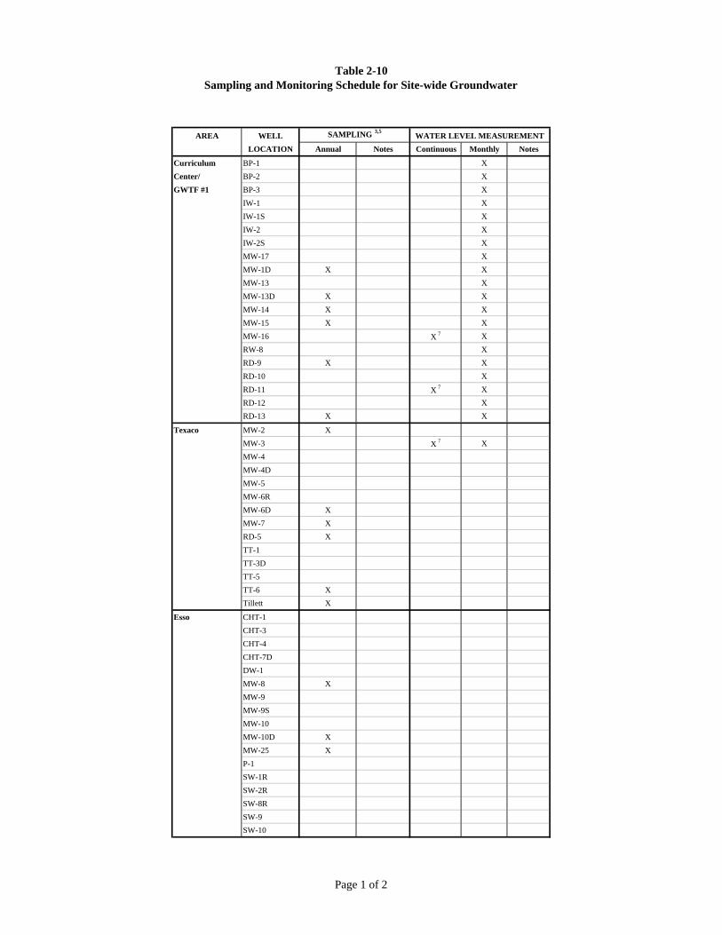
Table 2-10Sampling and Monitoring Schedule for Site-wide Groundwater
AREA WELL SAMPLING 3,5WATER LEVEL MEASUREMENT
LOCATION Annual Notes Continuous Monthly Notes
Curriculum BP-1 X
Center/ BP-2 X
GWTF #1 BP-3 X
IW-1 X
IW-1S X
IW-2 X
IW-2S X
MW-17 X
MW-1D X X
MW-13 X
MW-13D X X
MW-14 X X
MW-15 X X
MW-16 X 7 X
RW-8 X
RD-9 X X
RD-10 X
RD-11 X 7 X
RD-12 X
RD-13 X X
Texaco MW-2 X
MW-3 X 7 X
MW-4
MW-4D
MW-5
MW-6R
MW-6D X
MW-7 X
RD-5 X
TT-1
TT-3D
TT-5
TT-6 X
Tillett X
Esso CHT-1
CHT-3
CHT-4
CHT-7D
DW-1
MW-8 X
MW-9
MW-9S
MW-10
MW-10D X
MW-25 X
P-1
SW-1R
SW-2R
SW-8R
SW-9
SW-10
Page 1 of 2

Table 2-10Sampling and Monitoring Schedule for Site-wide Groundwater
AREA WELL SAMPLING 3,5WATER LEVEL MEASUREMENT
LOCATION Annual Notes Continuous Monthly Notes
GWTF #2 DW-2 X X 7 X
MW-11D X X
MW-12D X X
MW-19 X
RD-4 X
RD-7 X X
SW-6 X
Eglin I X
Eglin III X 6
Southern Delegard X 4,6
Plume Laplace X 4,6
MW-21D X X 7 X
PZ-4 X
RD-1 X X
RD-2 X X
RD-3 X 4 X
RD-6 X X
RD-8 X X
RD-14 X 7 X
Smith X 4,6
Steele X 4,6
Notes:
1. Not used
2. Not used
3. Sampling includes VOCs, unless otherwise noted.
6. Active supply well.
7. Continuous water levels will be collected by transducers.
Acronyms:
DO - dissolved oxygen
GWTF - groundwater treatment facility
O&M - operations and maintenance
ORP - oxidation reduction potential
RA - remedial action
TOC - total organic carbon
VOC - volatile organic compound
4. Sampling includes VOCs, TOC, nitrate, sulfate, chloride, and ethane/ethene (intrinsic biodegradation parameters).
5. Field measurements shall be taken for water level, turbidity, DO, temperature, conductivity, pH, and ORP at allwells during sampling.
Page 2 of 2

Control System Interlocks - GWTF #1
Alarm Condition Result #1 Result #2
Lin
e no
.
P&ID Tagname
HMI Tagname
Description HMI Tagname
Description Description
14 OS-1061 P6 CU300 fault status P6_FAIL P6 CU300 fault autodialer ch 615 OS-1071 P7 CU300 fault status P7_FAIL P7 CU300 fault autodialer ch 6
16 OS-1081 P9 CU300 fault status P9_FAIL P9 CU300 fault autodialer ch 617 OS-1200 NaOCl metering pump flow switch MP1_FAL MP-1 low flow alarm autodialer ch 818 OS-1210 anti-scalant metering pump flow sw MP2_FAL MP-2 low flow alarm autodialer ch 819 OS-1400 acid metering pump flow switch MP3_FAL MP-3 low flow alarm autodialer ch 820 OS-1500 B1_AUX air stripper blower aux contacts P1_OUT P1 run output21 OS-1500 B1_AUX air stripper blower aux contacts P2_OUT P2 run output22 OS-1500 &
OS-1610B1_AUX & B2_AUX
air stripper blower aux contacts & SVE blower MS auxillary contacts
HX_OUT heat exchanger run output
23 LSH-1200 NASC_LAH NaOCl secondary containment GWSYS_SD GW system shutdown autodialer ch 424 LSL-1200 NA_LAL NaOCl storage autodialer ch 725 LSH-1210 SASC_LAH anti-scalant secondary containment GWSYS_SD GW system shutdown autodialer ch 426 LSL-1210 SA_LAL anti-scalant storage autodialer ch 727 LSHH-1100 EQ_LAH equalization tank GWSYS_SD GW system shutdown autodialer ch 328 LSH-1100 EQ_LSH equalization tank P1_OUT P1 transfer pump run output29 LSH-1100 EQ_LSH equalization tank P2_OUT P2 transfer pump run output30 LSL-1100 EQ_LSL equalization tank P1_OUT P1 transfer pump run output31 LSL-1100 EQ_LSL equalization tank P2_OUT P2 transfer pump run output autodialer ch 332 LSLL-1100 EQ_LAL equalization tank GWSYS_SD GW system shutdown33 LSHH-1400 HCLSC_LAH muriatic acid secondary containment GWSYS_SD GW system shutdown autodialer ch 434 LSLL-1400 HCL_LAL muriatic acid storage autodialer ch 735 PSH-1300 FLTR_PAH filter differential pressure GWSYS_SD GW system shutdown autodialer ch 536 LSHH-1500 AS_LAH air stripper sump GWSYS_SD GW system shutdown autodialer ch 337 LSHH-1501 BLDG_LAH building secondary containment GWSYS_SD GW system shutdown autodialer ch 438 LSHH-1501 BLDG_LAH building secondary containment SVESYS_SD SVE system shutdown autodialer ch 439 PSL-1500 AS_PAL air stripper blower low pressure GWSYS_SD GW system shutdown autodialer ch 540 PSH-1500 AS_PAH air stripper blower high pressure GWSYS_SD GW system shutdown autodialer ch 541 FSL-1620 B2_FAL SVE blower low flow switch SVESYS_SD SVE system shutdown autodialer ch 5
Table 3-1
Page 1 of 2

Alarm Condition Result #1 Result #2L
ine
no.
P&ID Tagname
HMI Tagname
Description HMI Tagname
Description Description
42 TSH-1620 B2_TAH SVE blower high temperature SVESYS_SD SVE system shutdown autodialer ch 543 LSHH-1101 EQSC_LAH EQ tank secondary containment GWSYS_SD GW system shutdown autodialer ch 444 LSH-1590 EFF_LSHH effluent discharge GWSYS_SD GW system shutdown autodialer ch 345 LSHH-1610 KO_LSHH knockout tank high level SVESYS_SD SVE system shutdown autodialer ch 346 TSH-1625 HX_TAH heat exchanger high temperature GWSYS_SD GW system shutdown autodialer ch 547 TSH-1625 HX_TAH heat exchanger high temperature SVESYS_SD SVE system shutdown autodialer ch 548 LSH-1070 RW7_WTE RW-7 water table elevation P7_OUT P7 run output49 LSL-1070 RW7_WTE RW-7 water table elevation P7_OUT P7 run output50 LSLL-1070 RW7_WTE RW-7 water table elevation P7_OUT P7 run output autodialer ch 651 LSH-1080 RW9_WTE RW-9 water table elevation P9_OUT P9 run output52 LSL-1080 RW9_WTE RW-9 water table elevation P9_OUT P9 run output53 LSLL-1080 RW9_WTE RW-9 water table elevation P9_OUT P9 run output autodialer ch 654 FIT-1300 ASIN_FR air stripper influent flow transmitter GWSYS_SD GW system shutdown autodailer ch 555 AIT-1500 EFF_AAH effluent pH transmitter GWSYS_SD GW system shutdown autodailer ch 556 AIT-1500 EFF_AAL effluent pH transmitter GWSYS_SD GW system shutdown autodailer ch 5
NOTES:Any GW system shutdown causes autodialer ch 1 output. Any SVE system shutdown causes autodialer ch 2 output.P1 & P2 transfer pumps do not operate when in EQ Tank Bypass mode.SVE/Offgas systems have been offline since 2006.
Page 2 of 2

Control System Interlocks - GWTF #2
Alarm Condition Result #1 Result #2
Lin
e no
.
P&ID Tagname
HMI Tagname
Description HMI Tagname
Description Description
14 OS-2011 P1 CU300 fault status P1_FAIL P1 CU300 fault autodialer ch 615 OS-2021 P1S CU300 fault status P1S_FAIL P1S CU300 fault autodialer ch 6
16 OS-2200 NaOCl metering pump flow switch MP1_FAL MP-1 low flow alarm autodialer ch 817 OS-2210 anti-scalant metering pump flow sw MP2_FAL MP-2 low flow alarm autodialer ch 818 OS-2400 acid metering pump flow switch MP3_FAL MP-3 low flow alarm autodialer ch 819 OS-2500 B1_AUX air stripper blower aux contacts P2_OUT P2 run output20 LSH-2200 NASC_LAH NaOCl secondary containment GWSYS_SD GW system shutdown autodialer ch 421 LSL-2200 NA_LAL NaOCl storage autodialer ch 722 LSH-2210 SASC_LAH anti-scalant secondary containment GWSYS_SD GW system shutdown autodialer ch 423 LSL-2210 SA_LAL anti-scalant storage autodialer ch 724 LSHH-2100 EQ_LAH equalization tank GWSYS_SD GW system shutdown autodialer ch 325 LSH-2100 EQ_LSH equalization tank P2_OUT P2 transfer pump run output26 LSL-2100 EQ_LSL equalization tank P2_OUT P2 transfer pump run output autodialer ch 327 LSLL-2100 EQ_LAL equalization tank GWSYS_SD GW system shutdown28 LSHH-2400 HCLSC_LAH muriatic acid secondary containment GWSYS_SD GW system shutdown autodialer ch 429 LSLL-2400 HCL_LAL muriatic acid storage autodialer ch 730 PSH-2300 FLTR_PAH filter differential pressure GWSYS_SD GW system shutdown autodialer ch 531 LSHH-2500 AS_LAH air stripper sump GWSYS_SD GW system shutdown autodialer ch 332 LSHH-2501 BLDG_LAH building secondary containment GWSYS_SD GW system shutdown autodialer ch 433 PSL-2500 AS_PAL air stripper blower low pressure GWSYS_SD GW system shutdown autodialer ch 534 PSH-2500 AS_PAH air stripper blower high pressure GWSYS_SD GW system shutdown autodialer ch 535 LSH-2590 EFF_LSHH effluent discharge GWSYS_SD GW system shutdown autodialer ch 336 LSH-2010 RW1_WTE RW-1 water table elevation P7_OUT P7 run output37 LSL-2010 RW1_WTE RW-1 water table elevation P7_OUT P7 run output38 LSLL-2010 RW1_WTE RW-1 water table elevation P7_OUT P7 run output autodialer ch 639 LSH-2020 RW1S_WTE RW-1S water table elevation P8_OUT P8 run output40 LSL-2020 RW1S_WTE RW-1S water table elevation P8_OUT P8 run output41 LSLL-2020 RW1S_WTE RW-1S water table elevation P8_OUT P8 run output autodialer ch 6
Table 3-2
Page 1 of 2
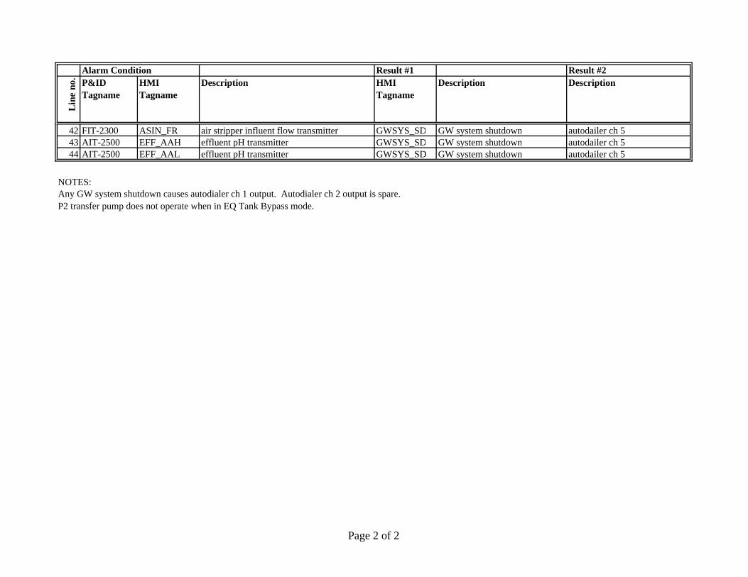
Alarm Condition Result #1 Result #2L
ine
no.
P&ID Tagname
HMI Tagname
Description HMI Tagname
Description Description
42 FIT-2300 ASIN_FR air stripper influent flow transmitter GWSYS_SD GW system shutdown autodailer ch 543 AIT-2500 EFF_AAH effluent pH transmitter GWSYS_SD GW system shutdown autodailer ch 544 AIT-2500 EFF_AAL effluent pH transmitter GWSYS_SD GW system shutdown autodailer ch 5
NOTES:Any GW system shutdown causes autodialer ch 1 output. Autodialer ch 2 output is spare.P2 transfer pump does not operate when in EQ Tank Bypass mode.
Page 2 of 2

Table 3-3Control Tag Database - GWTF #1
Tag Type Tag Name Tag Description Alarmed Data Logged Units Address
A alarm_status alarm status N NA all_alarms all alarms N ND AS_LAH air stripper sump LAH Y N B3:40/0D AS_PAH air stripper blower high pressure Y N B3:40/2D AS_PAL air stripper blower low pressure Y N B3:40/1A ASIN_100MG air stripper influent totalizer 100,000,000 gals N Y F8:22A ASIN_10KG air stripper influent 10K gals totalizer, 10K's gals N Y F8:23D ASIN_FAL air stripper influent low flow alarm Y Y b3:42/8A ASIN_FR air stripper influent flow rate, gpm N Y gpm F8:2A ASIN_G air stripperi nfluent totalizer, gals N Y gals F8:24D B1_0R B-1 stop request N Y B3:30/0A B1_100HRS air stripper blower runtime, 100 hrs N Y N7:0D B1_1R air stripper blower start req N Y B3:20/0D B1_AM air stripper blower auto / man N Y B3:10/0D B1_AUX air stripper blower aux contacts N Y I:0/11D B1_OUT B1 run output N Y O:0/8D B1_SERV B! in service N Y B3:4/8D B2_0R B-2 stop req N Y B3:31/0A B2_100HRS SVE blower 100 hours N Y N7:2D B2_1R B-2 start req N Y B3:20/9D B2_AM B-2 auto / man N Y B3:10/9D B2_AUX SVE blower MS auxillary contacts N Y I:1/0D B2_FAL SVE blower low flow alarm Y N B3:41/0D B2_OUT SVE blower run output N Y O:0/9D B2_SERV B2 in service N Y B3:4/9D B2_TAH SVE blower high temperature alarm Y N B3:41/1D BLDG_LAH building secondary containment alarm Y N B3:40/10D EFF_AAH effluent pH high alarm Y N B3:40/14D EFF_AAL effluent pH low alarm Y N B3:40/15D EFF_AIC_AM EFF-AIC auto / man N Y PD10:2/AMD EFF_AIC_CE EFF-AIC cycle enable N Y B3:50/2A EFF_AIC_CV EFF-AIC CV output, 0-16383 N Y PD10:2.CVPA EFF_AIC_OUT EFF-AIC CV output, 0-16383 N Y N9:83A EFF_AIC_SP EFF-AIC setpoint, 0-14 pH N Y PD10:2.SPSD EFF_LAH effluent high level alarm Y N B3:40/8
Page 1 of 5

Table 3-3Control Tag Database - GWTF #1
Tag Type Tag Name Tag Description Alarmed Data Logged Units Address
A EFF_PH effluent pH N Y F8:4D EQ_BYPASS EQ tank bypass mode N Y B3:4/13D EQ_ID MMI initiate EQ drain N Y B3:1/3D EQ_IF MMI initiate EQ tankfill N Y B3:1/8D EQ_LAH EQ tank high-high level Y N B3:40/5D EQ_LAL EQ tank low-low level Y N B3:40/6D EQ_LSH equalization tank N Y I:1/6D EQ_LSL equalization tank N Y I:1/7D EQINF_FAL equalization tank influent low flow alarm Y N B3:42/9A EQINF_FR EQ tank influent flow rate, gpm N Y F8:3A EQINF_LIM equalization tank influent flow rate low limit N Y f8:15D EQSC_LAH EQ tank secondary containment Y N B3:42/4D FLTR_PAH filter differential pressure high alarm Y N B3:40/9A GW_RTIME GW system runtime today N Y mins c5:6.accD GWSTOPPING GW system stopping N Y B3:0/6D GWSYS_SD GW system shutdown Y N B3:45/0D HCL_LAL muriatic acid low level alarm Y N b3:42/5D HCLSC_LAH muriatic acid secondary containment alarm Y N B3:40/7D HX_0R HX stop req N Y B3:31/1A HX_100HRS HX runtime, 100 hours N Y N7:20D HX_1R HX start req N Y B3:20/10D HX_AM HX auto / man N Y B3:10/10D HX_AUX heat exchanger aux N Y I:2/8D HX_OUT heat exchanger run output N Y O:3/6D HX_TAH HX high temperature Y N B3:40/11D KO_LAH SVE knockout tank high level alarm Y N B3:41/2D MMI_RESET system reset N Y B3:0/2D MMI_START system start N Y B3:0/0D MMI_STOP system stop N Y B3:0/1D MP1_0R MP-1 stop req N Y B3:30/6A MP1_100HRS MP1 runtime, 100 hours N Y N7:14D MP1_1R MP-1 start req N Y B3:20/6D MP1_AM MP-1 auto / man N Y B3:10/6A MP1_DRCONC NaOCl dosage rate from MMI, ppmv N Y F8:9A MP1_DRFLOW NaOCl dosage rate calculated in PLC, gal/hr N Y gph F8:11
Page 2 of 5

Table 3-3Control Tag Database - GWTF #1
Tag Type Tag Name Tag Description Alarmed Data Logged Units Address
D MP1_FAL MP1 low flow alarm Y N B3:40/12D MP1_OUT MP1 run output N Y O:0/3D MP1_SERV MP1 in service N Y B3:4/5D MP2_0R MP-2 stop req N Y B3:30/7A MP2_100HRS MP2 runtime, 100 hours N Y N7:16D MP2_1R MP-2 start req N Y B3:20/7D MP2_AM MP-2 auto / man N Y B3:10/7A MP2_DRCONC sequestering agentdosage rate from MMI, ppmv N Y ppmv F8:12A MP2_DRFLOW sequestering agent dosage rate calculated in PLC, gal/hr N Y gph F8:14D MP2_FAL MP2 low flow alarm Y N B3:40/13D MP2_OUT MP2 run output N Y O:0/4D MP2_SERV MP2 in service N Y B3:4/6D MP3_0R MP-3 stop req N Y B3:30/8A MP3_100HRS MP3 runtime, 100 hours N Y N7:18D MP3_1R MP-3 start req N Y B3:20/8D MP3_AM MP-3 auto / man N Y B3:10/8D MP3_OUT MP3 run output N Y O:0/7D MP3_SERV MP3 in service N Y B3:4/7D NA_LAL NaOCl low level alarm Y N b3:42/6D NASC_LAH NaOCl secondary containment alarm Y N B3:40/3D P1_0R P-1 stop req N Y B3:30/1A P1_100HRS P1 runtime, 100 hours N Y N7:4D P1_1R P-1 start req N Y B3:20/1D P1_AM P-1 auto / man N Y B3:10/1D P1_AUX P1 MS auxillary contacts N Y I:0/8D P1_OUT P1 run output N Y O:0/5D P1_SEL P1 select to run N Y b3:3/3D P1_SERV P1 in service N Y B3:4/0D P2_0R P-2 stop req N Y B3:30/2A P2_100HRS P2 runtime, 100 hours N Y N7:6D P2_1R P-2 start req N Y B3:20/2D P2_AM P-2 auto / man N Y B3:10/2D P2_AUX P2 MS auxillary contacts N Y I:0/9D P2_OUT P2 run output N Y O:0/6D P2_SEL P1 select to run N Y b3:3/4
Page 3 of 5

Table 3-3Control Tag Database - GWTF #1
Tag Type Tag Name Tag Description Alarmed Data Logged Units Address
D P2_SERV P2 in service N Y B3:4/13D P6_0R P-6 stop req N Y B3:30/3A P6_100HRS P6 runtime, 100 hours N Y N7:8D P6_1R P-6 start req N Y B3:20/3D P6_AM P-6 auto / man N Y B3:10/3D P6_AUX P6 CU300 run status N Y I:0/0D P6_FAIL P-6 auto shutdown Y N B3:45/4D P6_OUT P6 run output N Y O:0/0D P6_SERV P6 in service N Y B3:4/2D P7_0R P-7 stop req N Y B3:30/4A P7_100HRS P7 runtime, 100 hours N Y N7:10D P7_1R P-7 start req N Y B3:20/4D P7_AM P-7 auto / man N Y B3:10/4D P7_AUX P7 CU300 run status N Y I:0/2D P7_FAIL P-7 CU300 fault Y N B3:42/1D P7_OUT P7 run output N Y O:0/1D P7_SERV P7 in service N Y B3:4/3D P9_0R P-9 stop req N Y B3:30/5A P9_100HRS P9 runtime, 100 hours N Y N7:12D P9_1R P-9 start req N Y B3:20/5D P9_AM P-9 auto / man N Y B3:10/5D P9_AUX P9 CU300 run status N Y I:0/4D P9_FAIL P-9 CU300 fault Y N B3:42/3D P9_OUT P9 run output N Y O:0/2D P9_SERV P9 in service N Y B3:4/4D RW7_EXT_SP RW7-LIC external setpoint N Y f8:16D RW7_ID RW-7 pump down control N Y B3:1/15D RW7_LAL RW7 low level alarm Y N b3:42/0D RW7_LIC_AM RW7-LIC auto / man N Y PD10:0/AMD RW7_LIC_CE RW7-LIC cycle enable N Y B3:50/0A RW7_LIC_CV RW7-LIC CV, 0-100% N Y PD10:0.CVPA RW7_LIC_LE RW7-LIC extra logic enable N Y b3:51/0A RW7_LIC_OUT RW7-LIC CV output, 0-16383 N Y N9:23A RW7_LIC_SP RW7-LIC setpoint, 150-200 ft amsl N Y ft amsl PD10:0.SPSA RW7_LTEL RW-7 level transmitter elevation, ft amsl N Y F8:5
Page 4 of 5

Table 3-3Control Tag Database - GWTF #1
Tag Type Tag Name Tag Description Alarmed Data Logged Units Address
A RW7_WC RW-7 water column, ft N Y F8:0A RW7_WTE RW-7 water table elevation, ft amsl N Y F8:6D RW9_EXT_SP RW9-LIC external setpoint N Y f8:28D RW9_ID RW-9 pump down control N Y B3:2/5D RW9_LAL RW9 low level alarm Y N b3:42/2D RW9_LIC_AM RW9-LIC auto / man N Y PD10:1/AMD RW9_LIC_CE RW9-LIC cycle enable N Y B3:50/1A RW9_LIC_CV RW9-LIC CV, 0-100% N Y PD10:1.CVPA RW9_LIC_LE RW9-LIC extra logic enable N Y b3:51/1A RW9_LIC_OUT RW9-LIC CV output, 0-16383 N Y N9:53A RW9_LIC_SP RW9-LIC setpoint, 150-200 ft amsl N Y ft amsl PD10:1.SPSA RW9_LTEL RW-9 level transmitter elevation, ft amsl N Y F8:7A RW9_WC RW-9 water column, ft N Y F8:1A RW9_WTE RW-9 water tableelevation, ft amsl N Y F8:8D SA_LAL sequestering agent low level alarm Y N b3:42/7D SASC_LAH sequestering agent secondary containment alarm Y N B3:40/4D STARTING system starting N Y B3:0/3D STOPPED system stopped N Y B3:0/7D SVE_RTIME SVE system runtime today N Y mins c5:7.accD SVESYS_SD SVE system shutdown Y N B3:46/0A unacked_alarms unacknowledged alarms N N
Tag Type: A= analog (process variable, pv)D= discrete (status variable, sv)
SVE/Offgas systems have been offline since 2006.
Page 5 of 5

Table 3-4Control Tag Database - GWTF #2
Tag Type Tag Name Tag Description Alarmed Data Logged Units Address
A alarm_status alarm status N NA all_alarms all alarms N ND AS_LAH air stripper sump LAH Y N B3:40/0D AS_PAH air stripper blower high pressure Y N B3:40/2D AS_PAL air stripper blower low pressure Y N B3:40/1A ASIN_100MG air stripper influent totalizer 100,000,000 gals N Y F8:22A ASIN_10KG air stripper influent 10K gals totalizer, 10K's gals N Y F8:23D ASIN_FAL air stripper influent low flow alarm Y Y b3:42/8A ASIN_FR air stripper influent flow rate, gpm N Y gpm F8:2A ASIN_G air stripper influent totalizer, gals N Y gals F8:24D B1_0R B-1 stop request N Y B3:30/0A B1_100HRS air stripper blower runtime, 100 hrs N Y N7:0D B1_1R air stripper blower start req N Y B3:20/0D B1_AM air stripper blower auto / man N Y B3:10/0D B1_AUX air stripper blower aux contacts N Y I:0/11A B1_HRS air stripper blower runtime, hours N Y N7:1D B1_OUT B1 run output N Y O:0/8D BLDG_LAH building secondary containment alarm Y N B3:40/10D EFF_AAH effluent pH high alarm Y N B3:40/14D EFF_AAL effluent pH low alarm Y N B3:40/15D EFF_AIC_AM EFF-AIC auto / man N Y PD10:2/AMD EFF_AIC_CE EFF-AIC cycle enable N Y B3:50/2A EFF_AIC_CV EFF-AIC CV output, 0-16383 N Y PD10:2.CVPA EFF_AIC_OUT EFF-AIC CV output,0-16383 N Y N9:83A EFF_AIC_SP EFF-AIC setpoint, 0-14 pH N Y PD10:2.SPSD EFF_LAH effluent high level alarm Y N B3:40/8A EFF_PH effluent pH N Y F8:4D EQ_BYPASS EQ tank bypass mode N Y B3:1/10D EQ_ID MMI initiate EQ drain N Y B3:1/3D EQ_IF MMI initiate EQ tankfill N Y B3:1/8D EQ_LAH EQ tank high-high level Y N B3:40/5D EQ_LAL EQ tank low-low level Y N B3:40/6D EQ_LSH equalization tank N Y I:1/6D EQ_LSL equalization tank N Y I:1/7D EQINF_FAL EQ tank influent low flow alarm Y N B3:42/10
Page 1 of 4
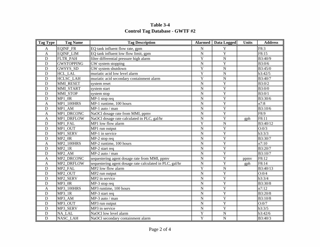
Table 3-4Control Tag Database - GWTF #2
Tag Type Tag Name Tag Description Alarmed Data Logged Units Address
A EQINF_FR EQ tank influent flow rate, gpm N Y F8:3A EQINF_LIM EQ tank influent low flow limit, gpm N Y F8:15D FLTR_PAH filter differential pressure high alarm Y N B3:40/9D GWSTOPPING GW system stopping N Y B3:0/6D GWSYS_SD GW system shutdown Y N B3:45/0D HCL_LAL muriatic acid low level alarm Y N b3:42/5D HCLSC_LAH muriatic acid secondary containment alarm Y N B3:40/7D MMI_RESET system reset N Y B3:0/2D MMI_START system start N Y B3:0/0D MMI_STOP system stop N Y B3:0/1D MP1_0R MP-1 stop req N Y B3:30/6A MP1_100HRS MP-1 runtime, 100 hours N Y n7:8D MP1_AM MP-1 auto / man N Y B3:10/6A MP1_DRCONC NaOCl dosage rate from MMI, ppmv N Y F8:9A MP1_DRFLOW NaOCl dosage rate calculated in PLC, gal/hr N Y gph F8:11D MP1_FAL MP1 low flow alarm Y N B3:40/12D MP1_OUT MP1 run output N Y O:0/3D MP1_SERV MP-1 in service N Y b3:3/3D MP2_0R MP-2 stop req N Y B3:30/7A MP2_100HRS MP-2 runtime, 100 hours N Y n7:10D MP2_1R MP-2 start req N Y B3:20/7D MP2_AM MP-2 auto / man N Y B3:10/7A MP2_DRCONC sequestering agent dosage rate from MMI, ppmv N Y ppmv F8:12A MP2_DRFLOW sequestering agent dosage rate calculated in PLC, gal/hr N Y gph F8:14D MP2_FAL MP2 low flow alarm Y N B3:40/13D MP2_OUT MP2 run output N Y O:0/4D MP2_SERV MP2 in service N Y b3:3/4D MP3_0R MP-3 stop req N Y B3:30/8A MP3_100HRS MP3 runtime, 100 hours N Y n7:12D MP3_1R MP-3 start req N Y B3:20/8D MP3_AM MP-3 auto / man N Y B3:10/8D MP3_OUT MP3 run output N Y O:0/7D MP3_SERV MP3 in service N Y b3:3/5D NA_LAL NaOCl low level alarm Y N b3:42/6D NASC_LAH NaOCl secondary containment alarm Y N B3:40/3
Page 2 of 4

Table 3-4Control Tag Database - GWTF #2
Tag Type Tag Name Tag Description Alarmed Data Logged Units Address
D P1_0R P-1 stop req N Y B3:30/4A P1_100HRS P1 runtime, 100 hours N Y N7:2D P1_1R P-1 start req N Y B3:20/4D P1_AM P-1 auto / man N Y B3:10/4D P1_AUX P1 CU300 run status N Y I:0/2D P1_FAIL P-1 CU300 fault Y N B3:42/1D P1_OUT P1 run output N Y O:0/1D P1_SERV P1 in service N Y B3:3/1D P1S_0R P-1S stop req N Y B3:30/5A P1S_100HRS P1S runtime, 100 hours N Y N7:4D P1S_1R P-1S start req N Y B3:20/5D P1S_AM P-1S auto / man N Y B3:10/5D P1S_AUX P1S CU300 run status N Y I:0/4D P1S_FAIL P-1S CU300 fault Y N B3:42/3D P1S_OUT P1S run output N Y O:0/2D P1S_SERV P1S in service N Y B3:3/2D P2_0R P-2 stop req N Y B3:30/1A P2_100HRS P2 runtime, 100 hours N Y N7:6D P2_1R P-2 start req N Y B3:20/1D P2_AM P-2 auto / man N Y B3:10/1D P2_AUX P2 MS auxillary contacts N Y I:0/6D P2_FAL P2 low flow alarm Y N B3:42/8D P2_OUT P2 run output N Y O:0/4D P2_SEL P2 select to run N Y b3:3/4D P2_SERV P2 in service N Y B3:3/0D RW1_ID RW-1 pump down control N Y B3:1/15D RW1_LAL RW1 low level alarm Y N b3:42/0D RW1_LIC_AM RW1-LIC auto / man N Y PD10:0/AMD RW1_LIC_CE RW1-LIC cycle enable N Y B3:50/0A RW1_LIC_CV RW1-LIC CV, 0-100% N Y PD10:0.CVPA RW1_LIC_OUT RW1-LIC CV output, 0-16383 N Y N9:23A RW1_LIC_SP RW1-LIC setpoint, 150-200 ft amsl N Y ft amsl PD10:0.SPSA RW1_LTEL RW-1 level transmitter elevation, ft amsl N Y F8:5A RW1_WC RW-1 water column, ft N Y F8:0A RW1_WTE RW-1 water table elevation, ft amsl N Y F8:6
Page 3 of 4

Table 3-4Control Tag Database - GWTF #2
Tag Type Tag Name Tag Description Alarmed Data Logged Units Address
D RW1S_ID RW-8 pump down control N Y B3:2/5D RW1S_LAL RW1S low level alarm Y N b3:42/2D RW1S_LIC_AM RW1S-LIC auto / man N Y PD10:1/AMD RW1S_LIC_CE RW1S-LIC cycle enable N Y B3:50/1A RW1S_LIC_CV RW1S-LIC CV, 0-100% N Y PD10:1.CVPA RW1S_LIC_OUT RW1S-LIC CV output,0-16383 N Y N9:53A RW1S_LIC_SP RW1S-LIC setpoint, 150-200 ft amsl N Y ft amsl PD10:1.SPSA RW1S_LTEL RW-1S level transmitter elevation, ft amsl N Y F8:7A RW1S_WC RW-1S water column, ft N Y F8:1A RW1S_WTE RW-1S water table elevation, ft amsl N Y F8:8D SA_LAL sequestering agent low level alarm Y N b3:42/7D SASC_LAH sequestering agent secondary containment alarm Y N B3:40/4D STARTING system starting N Y B3:0/3D STOPPED system stopped N Y B3:0/7D SYS_RTIME system runtime today N Y mins c5:6.accA unacked_alarms unacknowledged alarms N N
Tag Type: A= analog (process variable, pv)D= discrete (status variable, sv)
Page 4 of 4

Table 5-1Routine Operating Parameters - GWTF #1
Parameter Description Normal Value Upper Limit Lower Limit Units
RW-6 water table elevation 150 180 130 ft amslRecovery well pump P-6 pressure 30 160 0 psigRecovery well pump P-6 flow rate 4 7 0 gpmRW-7 water table elevation 153 180 135 ft amslRecovery well pump P-7 pressure 15 97 0 psigRecovery well pump P-7 flow rate 20 36 0 gpmRW-9 water table elevation 170 180 135 ft amslRecovery well pump P-9 pressure 20 82 0 psigRecovery well pump P-9 flow rate 10 27 0 gpmTransfer pump P-1 pumping rate (am) 30 - 35 60 4 gpmTransfer pump P-1 motor current 1.4 - 1.6 FLA = 1.8 --- ampsTransfer pump P-2 pumping rate (pm) 30 - 35 60 4 gpmTransfer pump P-1 and P-2 discharge pressure 27 40 20 psigTransfer pump P-2 motor current 1.4 - 1.6 FLA = 1.8 --- ampsNaOCl concentration in influent 20 na na ppmvNaOCl dosage rate 0.042 0.66 0 gal/hrMP-1 stroke length 100 100 0 %Sequesterant (20%) conc in influent 17 na na ppmvSequestering agent dosage rate 0.036 0.66 0 gal/hrMP-2 pump stroke length 100 100 20 %Bag filter differential pressure <12 20 0 psigAir stripper blower B-1 flow rate 300 - 350 400 300 scfmAir stripper blower B-1 motor current 16 - 18 FLA = 22.0 --- ampsAir stripper blower suction pressure 45 70 40 inches W.C. vacuumAir stripper blower discharge pressure 48 60 40 inches W.C. pressureAir stripper blower discharge temperature 190 160 220 °FEffluent pH 7.5 8.3 7 pH unitsSVE-1 wellhead vacuum 30 40 20 inches W.C. vacuumSVE influent flow rate 140 160 120 scfmSVE blower motor current 5.5 - 7.0 FLA = 8.0 --- ampsSVE blower suction pressure 30 40 20 inches W.C. vacuumSVE blower discharge pressure 45 60 40 inches W.C. pressureSVE blower discharge temperature 170 180 158 °FHeat exchanger motor current 1 - 1.4 FLA = 1.9 --- ampsHeat exchanger discharge temp 110 120 100 °FGAC #1 discharge pressure 30 --- --- inches W.C. pressureGAC #2 discharge pressure 15 --- --- inches W.C. pressureKMnO4 #1 discharge pressure 5 --- --- inches W.C. pressure
Note: SVE/Offgas systems have been offline since 2006.
Page 1 of 1

Table 5-2Routine Operating Parameters - GWTF #2
Parameter Description Normal Value Upper Limit Lower Limit Units
RW-1 water table elevation 111 150 85 ft amslRecovery well pump P-1 pressure 30 104 0 psigRecovery well pump P-1 flow rate 4 7 0 gpmRW-1S water table elevation 122 150 85 ft amslRecovery well pump P-1S pressure 20 97 0 psigRecovery well pump P-1S flow rate 15 36 0 gpmTransfer pump pumping rate 25 60 4 gpmTransfer pump motor current 1.4 - 1.6 FLA = 1.8 0 ampsTransfer pump discharge pressure 25 40 20 psigNaOCl concentration in influent 20 na na ppmvNaOCl dosage rate 0.03 0.66 0 gal/hrMP-1 stroke length 100 100 20 %Sequesterant (20%) conc in influent 12 na na ppmvSequestering agent dosage rate 0.018 0.66 0 gal/hrMP-2 stroke length 100 100 20 %Bag filter differential pressure <12 20 0 psigAir stripper blower B-1 flow rate 150 200 0 scfmAir stripper blower B-1 motor current 6.5 - 7 FLA = 8.0 0 ampsAir stripper blower suction pressure 43 70 30 inches W.C. vacuumAir stripper blower discharge pressure <10 --- --- inches W.C. pressureAir stripper blower discharge temperature 200 250 160 °FEffluent pH 7.5 8.3 7 pH units
Page 1 of 1

Page 1 of 2
Table 6-1 Routine and Preventative Maintenance Schedule – GWTF #1
System Task Recommend frequency
STAT 80 Air Stripper and Blower
Clean trays, and demister As needed, depending on the amount of hardness in the water. An initial inspection of the trays is suggested after the two to three weeks. If the differential pressure across the unit exceeds 7” of water pressure per tray, the system should be cleaned.
Clean site glass and level assembly
As needed, depending on the amount of hardness in the water. If the site glass every becomes rust colored, the site glass should be cleaned.
Replace tray gaskets. As needed. Blower filter cleaning or replacement
As needed, depending on air quality conditions
Grease blower motor bearings with NLGI #2. Grease, if applicable.
Yearly
Replace bearings After 15,000 – 20,000 hours, on average.
Bag Filters Clean/replace bag filters As needed, depending on the amount of sediment. If the differential pressure across the bag exceeds 12 psi, then the bag should be serviced.
Transfer Pumps Disassemble, inspect, and clean impeller housing
Yearly, but may require service more often if the water hardness level is high.
Grease motor with NLGI #2, if applicable.
Yearly
Chemical Feed Pumps
Monitor chemical usage Monitor the chemical usage rate at your convenience.
Check pump for proper zero position (stroke knob).
Periodically.
Replace Liquifram (Diaphragm), cartridge valves or seal rings/valve balls, valve cap assemblies, and injection check valve spring.
Yearly.

Page 2 of 2
System Task Recommend frequency
Exhaust Fans Lubricate motors using SAE 20 non-detergent oil.
Every six months.
Clean propeller blades and motor of excessive dirt.
Periodically.
Air Conditioners Lubricate fan motor using 2 – 3 drops of light machine oil.
Every three months.
Clean intake filter. Periodically. Roll-Up Doors Lubricate roller chains,
spur gears, guides, end brackets, bearings, and lock mechanisms.
Periodically.
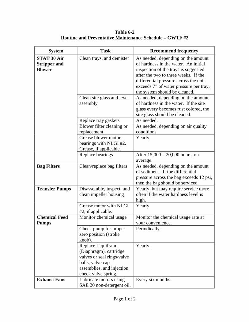
Page 1 of 2
Table 6-2 Routine and Preventative Maintenance Schedule – GWTF #2
System Task Recommend frequency
STAT 30 Air Stripper and Blower
Clean trays, and demister As needed, depending on the amount of hardness in the water. An initial inspection of the trays is suggested after the two to three weeks. If the differential pressure across the unit exceeds 7” of water pressure per tray, the system should be cleaned.
Clean site glass and level assembly
As needed, depending on the amount of hardness in the water. If the site glass every becomes rust colored, the site glass should be cleaned.
Replace tray gaskets As needed. Blower filter cleaning or replacement
As needed, depending on air quality conditions
Grease blower motor bearings with NLGI #2. Grease, if applicable.
Yearly
Replace bearings After 15,000 – 20,000 hours, on average.
Bag Filters Clean/replace bag filters As needed, depending on the amount of sediment. If the differential pressure across the bag exceeds 12 psi, then the bag should be serviced.
Transfer Pumps Disassemble, inspect, and clean impeller housing
Yearly, but may require service more often if the water hardness level is high.
Grease motor with NLGI #2, if applicable.
Yearly
Chemical Feed Pumps
Monitor chemical usage Monitor the chemical usage rate at your convenience.
Check pump for proper zero position (stroke knob).
Periodically.
Replace Liquifram (Diaphragm), cartridge valves or seal rings/valve balls, valve cap assemblies, and injection check valve spring.
Yearly.
Exhaust Fans Lubricate motors using SAE 20 non-detergent oil.
Every six months.

Page 2 of 2
System Task Recommend frequency
Clean propeller blades and motor of excessive dirt.
Periodically.
Air Conditioners Lubricate fan motor using 2 – 3 drops of light machine oil.
Every three months.
Clean intake filter. Periodically. Roll-Up Doors Lubricate roller chains,
spur gears, guides, end brackets, bearings, and lock mechanisms.
Periodically.

Page 1 of 2
Table 6-3 Spare Parts List
System Spare Part(s) Description On-Hand Upon Request
STAT 80 Air Stripper
Carbonair #211451 STAT 80 tray gasket X Carbonair #127581 STAT 30/80 polypropylene mist eliminator pad
X
Carbonair #117842 VL GD flapper X Carbonair #117923 Float ball 5 SS X Carbonair #211451 STAT 80 tray gasket X Carbonair #128272 Pressure gauge (0-100" wc) X Carbonair #108357 Sample port X Carbonair #124827 Dwyer model 1950-5 differential pressure switch
X
STAT 30 Air Stripper
Carbonair #117842 VL GD flapper X Carbonair #117923 Float ball 5 SS X Carbonair #211452 STAT30 tray gasket X Carbonair #128272 Pressure gauge (0-100" wc) X Carbonair #127581 STAT 30/80 polypropylene mist eliminator pad
X
Carbonair #108357 Sample port X Carbonair #124827 Dwyer model 1950-5 differential pressure switch
X
Bag Filters Carbonair #108357 Sample port X Carbonair #211320 25 Micron bag filter X Carbonair #210027 50 Micron bag filter X Carbonair #166980 Bag filter, oil removing X Carbonair #165924 Pressure gauge (0-60 psi) X Carbonair #108365 Pressure gauge (0-100 psi) X Carbonair #214737 O-ring for bag filter housing lid X Carbonair #214738 O-ring for bag filter basket X Carbonair #163286 Barksdale model DPD1T-GH80SS differential pressure switch (4-80 PSI)
X
Filter basket X Chemical Feed Pumps
No on-hand spare parts recommended. Spare Parts Kit or RPM ProPacs available from LMI. Refer to the information contained in Appendix C.
X
Well Pumps No on-hand spare parts recommended. Service kits and service tools available from Grundfos. Refer to the information contained in Appendix L.
X
Pressure Transducers
No on-hand spare parts recommended. Service provided by Pressure Systems. Refer to the information contained in Appendix L.
X
Transfer pumps No on-hand spare parts recommended. Replacement parts available from Corcoran. Refer to spare parts list in Appendix B.
X
Exhaust Fans No on-hand spare parts recommended. Replacement parts available from Dayton. Refer to spare parts list in Appendix M.
X
Air conditioners No on-hand spare parts recommended. Replacement parts available from Nordic Air. Refer to spare parts list in Appendix M.
X
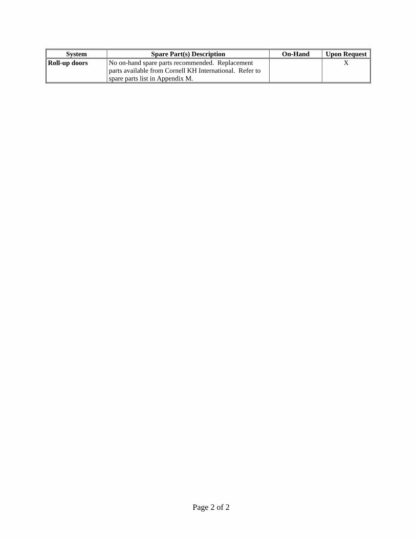
Page 2 of 2
System Spare Part(s) Description On-Hand Upon RequestRoll-up doors No on-hand spare parts recommended. Replacement
parts available from Cornell KH International. Refer to spare parts list in Appendix M.
X

Page 1 of 1
Table 7-1 Routine Inspection, Monitoring, and Maintenance Schedule
Daily/Weekly Checklist Items
Check/record readings from all instruments, meters, and gauges Check overall plant operations Check OIT/PLC for alarm conditions Check all valve positions Change bag filters when DP reaches 12 psig Pull weeds and clean grounds Check all sumps in the SVE lines and drain if necessary
Monthly Checklist Items Check off-gas treatment vessels and stacks for moisture collection Check well vaults and pull boxes for leaks Restart computers
Quarterly Checklist Items Turn all valves
Bi-Annual Checklist Items Change eyewash liquid Lubricate exhaust fan motors Lubricate roll-up doors
Annual Checklist Items Grease fittings on blowers Grease/lubricate all motors Grease transfer pump and clean impeller housing as needed Pull and check well pump for biofouling Shock-chlorinate recovery wells as needed Clean transformers (certified electrician) Clean exhaust fan blades
Periodic / As-Needed Checklist Items Drain moisture separator Clean or replace blower inlet air filters (all blowers) Clean AC intake filter Empty condensate collection drums at TU#2 and TU#4 and treat at TU#3
NOTE: Refer to Tables 6-1 and 6-2 for additional details regarding routine maintenance.

Page 1 of 6
Table 8-1 General Troubleshooting Guidelines – GWTF #1
System Problem Possible Cause Solution
GWTF #1 - Overview
One or more components will not run in AUTO
System-wide shutdown conditions exist
Examine the ALARM screen, acknowledge any existing alarms, click the RESET button at the top of any screen, and investigate any remaining alarm conditions. All alarm conditions capable of preventing AUTO operation are listed in Table 3-1.
SVE Blower1 Blower will run in “MAN” but not in “AUTO”
Alarm conditions – General
Clear any alarm condition and reset the control panel, see “Section 3” for alarm interlocks. Conditions with obvious solutions include high KO tank water level, secondary containment leak detection. See HX troubleshooting for high HX discharge temperature.
Low flow alarm Remove and inspect flow switch and flapper. Check continuity across switch terminals with flapper in up and down positions. If switching action is not detected, replace switch. If switching action is detected, examine flapper for scale or corrosion buildup. Clean and replace.
SVE blower high discharge temperature
Check for low flow situation (may not be low enough for a low flow alarm), high differential pressure across the inlet filter, or high discharge pressure indicating blockage in the off-gas treatment system. Clean or replace filter. Check vacuum at wellhead versus KO tank and determine if pressure losses are excessive. Check for blockage in piping. Check pressure drops across GAC and KMnO4 vessels.
Blower will not run in the “MAN” position
Tripped circuit protector
Open the inner door and reset the circuit protector. Inspect the system thoroughly and check the operating conditions. If it will run at least momentarily, check amps at startup and compare to initial operating conditions.
Motor temperature switch is inoperative
Check to see that the motor temperature switch has been wired, or that there is a jumper, if a switch is not present.
Faulty Blower
Refer to Appendix or contact CARBONAIR for help in diagnosing faulty blower.

Page 2 of 6
System Problem Possible Cause Solution
Blower runs at a reduced performance
Incorrect blower rotation
Verify and change rotation
Inlet filter fouled Clean or replace inlet filter Excessive effluent pressure
Verify operating condition. Ensure that there is not excessive backpressure on the unit, (eg, fouled Carbon bed)
Moisture separator relief valve set to low
Adjust pressure relief valve, be careful not to overload blower motor
Abnormal sound Impeller rubbing against housing
Adjust impeller
Inlet filter fouled Clean or replace inlet filter Bearings defective Change bearings
Motor overheats Impeller rubbing against housing
Adjust impeller
Inlet filter fouled Clean or replace inlet filter Bearings defective Change bearings One phase of stator winding short circuited
Rewind or purchase new motor
Operating beyond performance range
Reduce system pressure/vacuum
Well Pumps Pump will run in “MAN” but not in “AUTO”
Alarm conditions – General
Clear any alarm condition and reset the control panel. See “Section 3” for alarm interlocks.
CU300 fault Check the CU300 controller for a fault condition. Follow instructions in Grundfos® manual for troubleshooting
Well water level is below the cycle off level.
Check the LSL switch setting in the interlocks Table and allow the aquifer sufficient time to re-charge the well. When the water table elevation exceeds the low level switch, click the START button on the pump control panel.
Pump will not run in the “MAN” position
CU300 controller not properly setup for remote control.
Check CU300 controller for proper setup for remote control of on-off and motor speed.
PID controller output set to 0%
Adjust the PID controller output.
Tripped circuit protector
Open the inner door and reset the circuit protector. Inspect the system thoroughly and check the operating conditions.
Motor temperature switch is inoperative
Check to see that the motor temperature switch has been wired, or that there is a jumper, if a switch is not present.

Page 3 of 6
System Problem Possible Cause Solution
Faulty pump
Refer to Appendix or contact CARBONAIR for help in diagnosing faulty pump.
Pump operating, but at reduced performance
Incorrect pump rotation
Verify and change rotation
Pumping sediment The pump may be too close to the bottom of the well. Move the pump up.
Pump restricted Inspect and clean all effluent lines. Check to ensure that discharge valves are open.
STAT Air Stripper
Water in air discharge line
Water flow rate too high
Verify water flow rate conditions and adjust flow rate accordingly
Air flow rate too high Verify airflow rate conditions and adjust flow rate accordingly.
Foaming Contact CARBONAIR for a foaming test kit.
High Pressure Drop Pressure in the unit exceeds the recommended maximum (9” H2O per tray).
Water flow rate too high
Verify water flow rate conditions and adjust flow rate accordingly
Air flow rate too high Verify airflow rate conditions and adjust flow rate accordingly.
Excessive effluent pressure
Verify operating condition. Ensure that there is not excessive backpressure on the unit, (i.e. reduced pipe sizes, fouled Carbon bed, or fouled CATOX.)
Trays fouled Inspect and clean trays
Reduction in treatment performance
Inadequate air/water ratio
Verify that the system flows are within design specifications
Aeration trays are fouled
Clean STAT trays
Leaky Gaskets Pressure drop too high See “STAT-High Pressure Drop” section
Damaged gaskets Replace leaky gasket
STAT Blower1
Blower will run in “MAN” but not in “AUTO”
Alarm conditions – General
Clear any alarm condition and reset the control panel. See “Section 3” for alarm interlocks.
High pressure alarm Check for high discharge pressure indicating blockage in the off-gas treatment system. Check pressure drops across GAC and KMnO4 vessels. Check for proper operation of the discharge check valve. Check for adequate accumulation of water on air stripper trays. Check pressure switch adjustment.

Page 4 of 6
System Problem Possible Cause Solution
Low pressure alarm Check the inlet filter and clean or replace as necessary. Check air stripper trays for fouling and clean if necessary. Check pressure switch adjustment.
Blower will not run in the “MAN” position
Tripped circuit protector
Open the inner door and reset the circuit protector. Inspect the system thoroughly and check the operating conditions. . If it will run at least momentarily, check amps at startup and compare to initial operating conditions.
Motor temperature switch is inoperative
Check to see that the motor temperature switch has been wired, or that there is a jumper, if a switch is not present.
Faulty Blower
Refer to Appendix or contact CARBONAIR for help in diagnosing faulty blower.
Blower runs at a reduced performance
Incorrect blower rotation
Verify and change rotation
Inlet filter fouled Clean or replace inlet filter
Excessive effluent pressure
See “STAT-High Pressure Drop” section
Abnormal sound Impeller rubbing against housing
Adjust impeller
Inlet filter fouled Clean or replace inlet filter
Bearings defective Change bearings
Motor overheats Impeller rubbing against housing
Adjust impeller
Inlet filter fouled Clean or replace inlet filter
Bearings defective Change bearings
One phase of stator winding short circuited
Rewind or purchase new motor
Operating beyond performance range
Reduce system pressure/vacuum
Transfer Pumps
Pump will run in “MAN” but not in “AUTO”
Alarm conditions – General
Clear any alarm condition and reset the control panel. See “Section 3” for alarm interlocks.
Equalization tank water level too low
Fill the tank to any level above the LSL (cycle off level) and click the START button on the pump control panel.
Pump will not run in the “MAN” position
Tripped circuit protector
Open the inner door and reset the circuit protector. Inspect the system thoroughly and check the operating conditions. . If it will run at least momentarily, check amps at startup and compare to initial operating conditions.

Page 5 of 6
System Problem Possible Cause Solution
Motor temperature switch is inoperative
Check to see that the motor temperature switch has been wired, or that there is a jumper, if a switch is not present.
Faulty pump
Refer to Appendix or contact CARBONAIR for help in diagnosing faulty pump.
Pump operating, but at reduced performance
Incorrect pump rotation
Verify and change rotation
Pump restricted Inspect and clean all influent lines, pump head and effluent lines.
Pump leaking at seal
Shaft seal worn Replace shaft seal
Leak in system Inspect system for leaks
Chemical Feed Pumps
Pump will run in “MAN” but not in “AUTO”
Low flow alarm Check Digi-Pulse unit for proper operation, adjustment and pulse output.
Pump will not run in the “MAN” position
PID controller output or dosage rate too low.
Check PID controller output on PID screen and adjust as necessary. Check dosage rate on PID screen and enter new value as necessary.
Pump loses prime Out of Chemical Add more chemical
Check valve not working or installed incorrectly
See Appendix for installation, make sure check valve functioning.
Pump will not prime
Output not set properly
Set speed and stroke to 100%
Suction lift too high Lower pump
Pump fails to pump
Worn seal ring, or diaphragm.
Inspect and replace damaged item
Stroke setting too low Adjust setting to a higher value
Pump in not getting power
Confirm that the pump is getting power and be sure that the pump is enabled.
Pump has failed Refer to Appendix or contact CARBONAIR for help in diagnosing faulty pump.
GPC Vessels1 Early breakthrough or increased carbon usage
Actual concentrations higher than designed
Sample and Analyze influent water to determine if design contaminants or concentrations are different than anticipated. Contact Carbonair for revised modeling
Additional contaminants present High inlet temperature Add heat exchanger
High inlet relative Humidity
Add in-line duct heater for humidity control
Higher than normal pressure drop
High inlet temperature Check heat exchanger discharge temperature switch for proper operation.
High inlet relative Humidity
Check GPC inlet piping for mist or water droplets and, if found, troubleshoot the air stripper as described earlier.

Page 6 of 6
System Problem Possible Cause Solution
Accumulation of particles
Sample the carbon to determine if solids are clogging the bed. Back track to determine the source and correct
Wet carbon Dry out the carbon bed by draining any condensate and blow clean-dry air through the vessel.
Exhaust Fan Excessive noise Noisy motor bearings Lubricate or replace bearings
Loose fan blade Tighten set screws
Crooked or damaged propeller
Straighten or replace fan blade
Insufficient air flow
Damper (shutter) closed/shut
Repair shutter
Low voltage Determine cause and correct
Note: 1. SVE/Offgas systems have been offline since 2006.

Page 1 of 4
Table 8-2 General Troubleshooting Guidelines – GWTF #2
System Problem Possible Cause Solution
GWTF #2 - Overview
One or more components will not run in AUTO
System-wide shutdown conditions exist
Examine the ALARM screen, acknowledge any existing alarms, click the RESET button at the top of any screen, and investigate any remaining alarm conditions. All alarm conditions capable of preventing AUTO operation are listed in Table 3-2.
Well Pumps Pump will run in “MAN” but not in “AUTO”
Alarm conditions – General
Clear any alarm condition and reset the control panel. See “Section 3” for alarm interlocks.
CU300 fault Check the CU300 controller for a fault condition. Follow instructions in Grundfos® manual for troubleshooting
Well water level is below the cycle off level.
Check the LSL switch setting in the interlocks Table and allow the aquifer sufficient time to re-charge the well. When the water table elevation exceeds the low level switch, click the START button on the pump control panel.
Pump will not run in the “MAN” position
CU300 controller not properly setup for remote control.
Check CU300 controller for proper setup for remote control of on-off and motor speed.
PID controller output set to 0%
Adjust the PID controller output.
Tripped circuit protector
Open the inner door and reset the circuit protector. Inspect the system thoroughly and check the operating conditions.
Motor temperature switch is inoperative
Check to see that the motor temperature switch has been wired, or that there is a jumper, if a switch is not present.
Faulty pump
Refer to Appendix or contact CARBONAIR for help in diagnosing faulty pump.
Pump operating, but at reduced performance
Incorrect pump rotation
Verify and change rotation
Pumping sediment The pump may be too close to the bottom of the well. Move the pump up.
Pump restricted Inspect and clean all effluent lines. Check to ensure that discharge valves are open.

Page 2 of 4
System Problem Possible Cause Solution
STAT Air Stripper
Water in air discharge line
Water flow rate too high
Verify water flow rate conditions and adjust flow rate accordingly
Air flow rate too high Verify airflow rate conditions and adjust flow rate accordingly.
Foaming Contact CARBONAIR for a foaming test kit.
High Pressure Drop Pressure in the unit exceeds the recommended maximum (9” H2O per tray).
Water flow rate too high
Verify water flow rate conditions and adjust flow rate accordingly
Air flow rate too high Verify airflow rate conditions and adjust flow rate accordingly.
Excessive effluent pressure
Verify operating condition. Ensure that there is not excessive backpressure on the unit.
Trays fouled Inspect and clean trays
Reduction in treatment performance
Inadequate air/water ratio
Verify that the system flows are within design specifications
Aeration trays are fouled
Clean STAT trays
Leaky Gaskets Pressure drop too high See “STAT-High Pressure Drop” section
Damaged gaskets Replace leaky gasket
STAT Blower
Blower will run in “MAN” but not in “AUTO”
Alarm conditions – General
Clear any alarm condition and reset the control panel. See “Section 3” for alarm interlocks.
High pressure alarm Check for high discharge pressure indicating blockage in the off-gas discharge piping. Check for adequate accumulation of water on air stripper trays. Check pressure switch adjustment.
Low pressure alarm Check the inlet filter and clean or replace as necessary. Check air stripper trays for fouling and clean if necessary. Check pressure switch adjustment.
Blower will not run in the “MAN” position
Tripped circuit protector
Open the inner door and reset the circuit protector. Inspect the system thoroughly and check the operating conditions. . If it will run at least momentarily, check amps at startup and compare to initial operating conditions.
Motor temperature switch is inoperative
Check to see that the motor temperature switch has been wired, or that there is a jumper, if a switch is not present.
Faulty Blower
Refer to Appendix or contact CARBONAIR for help in diagnosing faulty blower.
Blower runs at a reduced performance
Incorrect blower rotation
Verify and change rotation
Inlet filter fouled Clean or replace inlet filter

Page 3 of 4
System Problem Possible Cause Solution
Excessive effluent pressure
See “STAT-High Pressure Drop” section
Abnormal sound Impeller rubbing against housing
Adjust impeller
Inlet filter fouled Clean or replace inlet filter
Bearings defective Change bearings
Motor overheats Impeller rubbing against housing
Adjust impeller
Inlet filter fouled Clean or replace inlet filter
Bearings defective Change bearings
One phase of stator winding short circuited
Rewind or purchase new motor
Operating beyond performance range
Reduce system pressure/vacuum
Transfer Pump
Pump will run in “MAN” but not in “AUTO”
Alarm conditions – General
Clear any alarm condition and reset the control panel. See “Section 3” for alarm interlocks.
Equalization tank water level too low
Fill the tank to any level above the LSL (cycle off level) and click the START button on the pump control panel.
Pump will not run in the “MAN” position
Tripped circuit protector
Open the inner door and reset the circuit protector. Inspect the system thoroughly and check the operating conditions. . If it will run at least momentarily, check amps at startup and compare to initial operating conditions.
Motor temperature switch is inoperative
Check to see that the motor temperature switch has been wired, or that there is a jumper, if a switch is not present.
Faulty pump
Refer to Appendix or contact CARBONAIR for help in diagnosing faulty pump.
Pump operating, but at reduced performance
Incorrect pump rotation
Verify and change rotation
Pump restricted Inspect and clean all influent lines, pump head and effluent lines.
Pump leaking at seal
Shaft seal worn Replace shaft seal
Leak in system Inspect system for leaks
Chemical Feed Pumps
Pump will run in “MAN” but not in “AUTO”
Low flow alarm Check Digi-Pulse unit for proper operation, adjustment and pulse output.
Pump will not run in the “MAN” position
PID controller output or dosage rate too low.
Check PID controller output on PID screen and adjust as necessary. Check dosage rate on PID screen and enter new value as necessary.

Page 4 of 4
System Problem Possible Cause Solution
Pump loses prime Out of Chemical Add more chemical
Check valve not working or installed incorrectly
See Appendix for installation, make sure check valve functioning.
Pump will not prime
Output not set properly
Set speed and stroke to 100%
Suction lift too high Lower pump
Pump fails to pump Worn seal ring, or diaphragm.
Inspect and replace damaged item
Stroke setting too low Adjust setting to a higher value
Pump in not getting power
Confirm that the pump is getting power and be sure that the pump is enabled.
Pump has failed Refer to Appendix or contact CARBONAIR for help in diagnosing faulty pump.
Exhaust Fan Excessive noise Noisy motor bearings Lubricate or replace bearings
Loose fan blade Tighten set screws
Crooked or damaged propeller
Straighten or replace fan blade
Insufficient air flow
Damper (shutter) closed/shut
Repair shutter
Low voltage Determine cause and correct


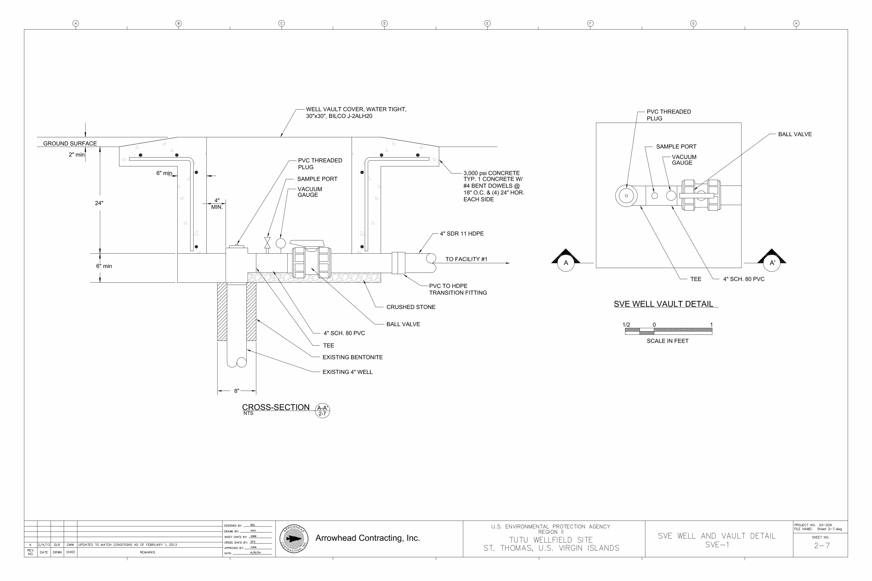
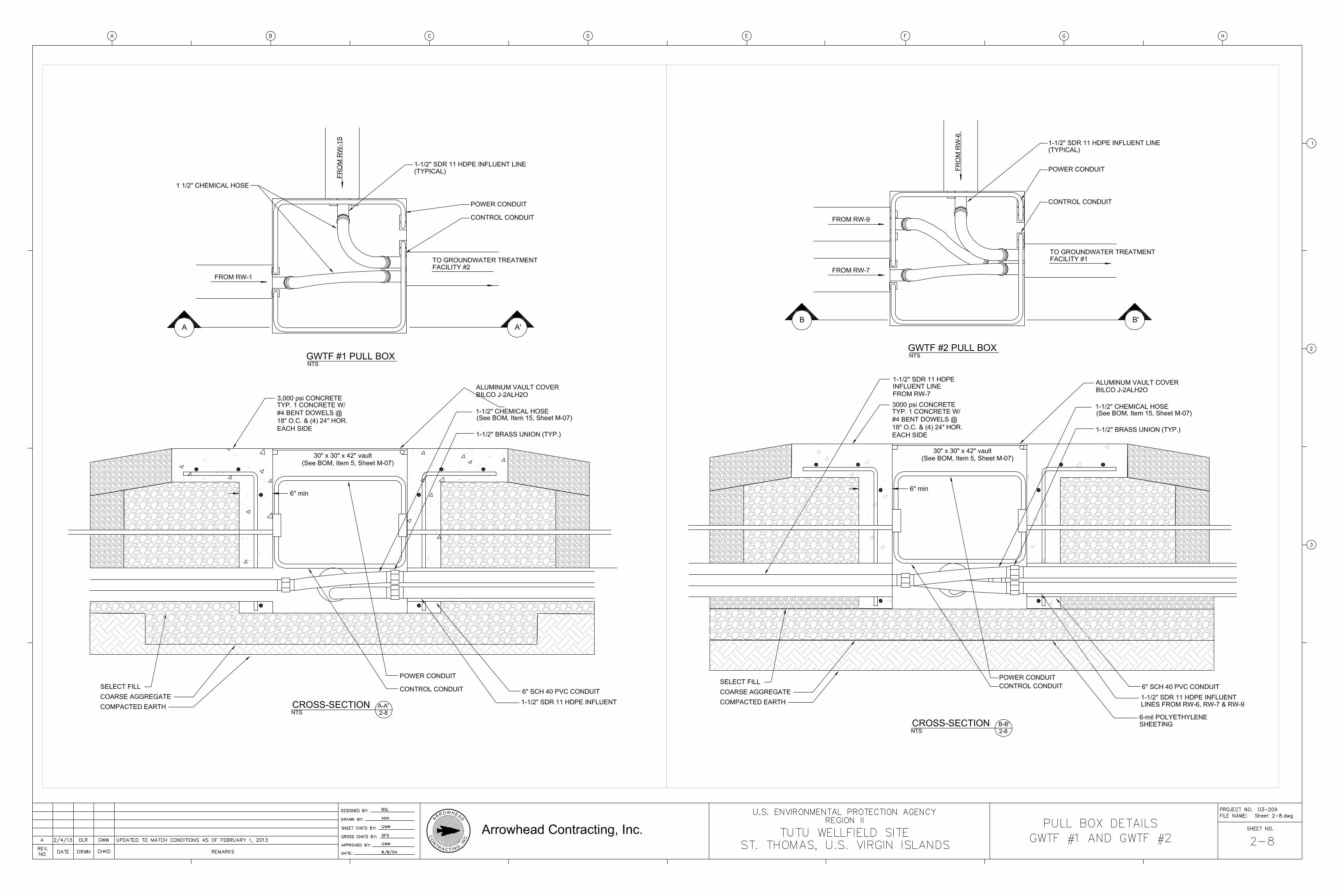


Recommended